results: mine area clearance vehicle … · afrl-rx-ty-tr-2009-4583 . results: mine area clearance...
TRANSCRIPT

AFRL-RX-TY-TR-2009-4583 RESULTS: MINE AREA CLEARANCE VEHICLE (MACV) EXPLOSIVES EXPERIMENTS FINAL TEST REPORT Kenneth J. Knox, PhD Applied Research Associates P.O. Box 40128 Tyndall AFB, FL 32403 SEPTEMBER 2005 Final Report for 6 September 2005 to 30 September 2005
Distribution Statement A: Approved for public release; distribution unlimited.
AIRBASE TECHNOLOGIES DIVISION MATERIALS AND MANUFACTURING DIRECTORATE
AIR FORCE RESEARCH LABORATORY AIR FORCE MATERIAL COMMAND
139 BARNES DRIVE, SUITE 2 TYNDALL AIR FORCE BASE, FL 32403-5323

NOTICE AND SIGNATURE PAGE
Using Government drawings, specifications, or other data included in this document for any purpose other than Government procurement does not in any way obligate the U.S. Government. The fact that the Government formulated or supplied the drawings, specifications, or other data does not license the holder or any other person or corporation; or convey any rights or permission to manufacture, use, or sell any patented invention that may relate to them. This report was cleared for public release by the Air Force Research Laboratory, Materials and Manufacturing Directorate, Airbase Technologies Division, Public Affairs and is available to the general public, including foreign nationals. Copies may be obtained from the Defense Technical Information Center (DTIC) (http://www.dtic.mil). REPORT NUMBER AFRL-RX-TY-TR-2009-4583 HAS BEEN REVIEWED AND IS APPROVED FOR PUBLICATION IN ACCORDANCE WITH ASSIGNED DISTRIBUTION STATEMENT. ___//signature//__________________________ ___//signature//____________________________ WALTER M. WALTZ JOHN S. MASCELLI, Captain, USAF Work Unit Manager Acting Chief, Force Protection Branch ___//signature//__________________________ ALBERT N. RHODES, PhD Acting Chief, Airbase Technologies Division This report is published in the interest of scientific and technical information exchange, and its publication does not constitute the Government’s approval or disapproval of its ideas or findings.
Standard Form 298 (Rev. 8/98)
REPORT DOCUMENTATION PAGE
Prescribed by ANSI Std. Z39.18
Form Approved OMB No. 0704-0188
The public reporting burden for this collection of information is estimated to average 1 hour per response, including the time for reviewing instructions, searching existing data sources, gathering and maintaining the data needed, and completing and reviewing the collection of information. Send comments regarding this burden estimate or any other aspect of this collection of information, including suggestions for reducing the burden, to Department of Defense, Washington Headquarters Services, Directorate for Information Operations and Reports (0704-0188), 1215 Jefferson Davis Highway, Suite 1204, Arlington, VA 22202-4302. Respondents should be aware that notwithstanding any other provision of law, no person shall be subject to any penalty for failing to comply with a collection of information if it does not display a currently valid OMB control number. PLEASE DO NOT RETURN YOUR FORM TO THE ABOVE ADDRESS. 1. REPORT DATE (DD-MM-YYYY) 2. REPORT TYPE 3. DATES COVERED (From - To)
4. TITLE AND SUBTITLE 5a. CONTRACT NUMBER
5b. GRANT NUMBER
5c. PROGRAM ELEMENT NUMBER
5d. PROJECT NUMBER
5e. TASK NUMBER
5f. WORK UNIT NUMBER
6. AUTHOR(S)
7. PERFORMING ORGANIZATION NAME(S) AND ADDRESS(ES) 8. PERFORMING ORGANIZATION REPORT NUMBER
9. SPONSORING/MONITORING AGENCY NAME(S) AND ADDRESS(ES) 10. SPONSOR/MONITOR'S ACRONYM(S)
11. SPONSOR/MONITOR'S REPORT NUMBER(S)
12. DISTRIBUTION/AVAILABILITY STATEMENT
13. SUPPLEMENTARY NOTES
14. ABSTRACT
15. SUBJECT TERMS
16. SECURITY CLASSIFICATION OF: a. REPORT b. ABSTRACT c. THIS PAGE
17. LIMITATION OF ABSTRACT
18. NUMBER OF PAGES
19a. NAME OF RESPONSIBLE PERSON
19b. TELEPHONE NUMBER (Include area code)
06-SEP-2005 Final Technical Report 06-SEP-2005 -- 30-SEP-2005
Results: Mine Area Clearance Vehicle (MACV) Explosive Experiments Final Test Report
FA4819-07-D-0001
99999F
GOVT
F0
Q240FC6G
Knox, Kenneth J., PhD
Applied Research Associates P.O. Box 40128 Tyndall Air Force Base, FL 32403
Air Force Research Laboratory Materials and Manufacturing Directorate Airbase Technologies Division 139 Barnes Drive, Suite 2 Tyndall Air Force Base, FL 32403-5323
AFRL/RXQF
AFRL-RX-TY-TR-2009-4583
Distribution Statement A: Approved for public release; distribution unlimited.
Ref AFRL/RXQ Public Affairs Case # 09-190. Document contains color images.
The Hydrema 910 Mine Area Clearance Vehicle (MACV), a Danish mine clearing system, is being converted to teleremote operations by the Air Force Research Laboratory (AFRL) for the HQ Air Combat Command Civil Engineer (HQ ACC/CE). On 8 July 2005 AFRL conducted a series of experiments to evaluate and demonstrate the survivability of the robotic controls during simulated mine clearing operations. The MACV was exposed to a range of munitions detonated adjacent to the mine-clearing flail, ranging from antipersonnel weapons to antitank weapons. None of the weapons had an appreciable effect on the MACV or on the robotic controls contained in the operator's cab. The vehicle cab was exposed to approximately 5.5 psi incident pressures on the exterior, but the interior pressure increased less than 0.2 psi. The magnitude of shock experienced by the cab and the robotic controls was 8.7 g's or less, well within the proven capacity of the control systems of 19.5 g's. Overall, the MACV did a good job protecting the cab and the robotic controls in the experiment series.
MACV, MACE, mine clearance, flail, teleremote, Hydrema, Perkins, sensors, robotic, ACC, vehicle cab, GPS, C-130
U U U UU 25
Walter M. Waltz
(850) 283-3725
Reset

Results: Mine Area Clearance Vehicle (MACV) Explosive Experiments
TABLE OF CONTENTS
1.0 Executive Summary ....................................................................................................3 2.0 Background .................................................................................................................3 3.0 References ...................................................................................................................5 4.0 Objectives and Technical Approach ...........................................................................5 4.1 Objective ..............................................................................................................5 4.2 Technical Approach .............................................................................................5 4.3 Data Collection ....................................................................................................6 5.0 Experimental Results ..................................................................................................6 5.1 Test 1: 10-lb C-4 Charge......................................................................................7 5.2 Test 2: M67 Frag Grenade ...................................................................................9 5.3 Test 3: BLU-97 CEM.........................................................................................10 5.4 Test 4: M15 Mine...............................................................................................11 6.0 Discussion .................................................................................................................13 7.0 Conclusions ...............................................................................................................14 Appendix: Data Graphs.............................................................................................15
FIGURES 1. Hydrema 910 Mine Area Clearance Vehicle ..............................................................5 2. Explosive Placement...................................................................................................6 3. Instrumentation Inside Operator’s Cab.......................................................................7 4. Pre-test: 10-lb C-4 Charge ..........................................................................................8 5. Post-test: 10-lb C-4 Charge.........................................................................................8 6. Pre-test: M67 Grenade ................................................................................................9 7. Post-test: M67 Grenade...............................................................................................9 8. Pre-test: BLU-97 CEM .............................................................................................10 9. Post-test: BLU-97 CEM............................................................................................11 10. Pre-test: M15 Mine ...................................................................................................12 11. Post-test: M15 Mine..................................................................................................12 12. MACV Pressure Measurements................................................................................13 13. MACV Cab Accelerations ........................................................................................14
TABLES 1. Test 1 Results..............................................................................................................8 2. Test 2 Results............................................................................................................10 3. Test 3 Results............................................................................................................11 4. Test 4 Results............................................................................................................13
iii
Results: Mine Area Clearance Vehicle (MACV) Explosive Experiments
RESULTS: MINE AREA CLEARANCE VEHICLE (MACV) EXPLOSIVE EXPERIMENTS
1.0 Executive Summary The Hydrema 910 Mine Area Clearance Vehicle (MACV), a Danish mine clearing system, is being converted to teleremote operations by the Air Force Research Laboratory (AFRL) for the HQ Air Combat Command Civil Engineer (HQ ACC/CE). On 8 July 2005 AFRL conducted a series of experiments to evaluate and demonstrate the survivability of the robotic controls during simulated mine clearing operations. The MACV was exposed to a range of munitions detonated adjacent to the mine-clearing flail, ranging from antipersonnel weapons to antitank weapons. None of the weapons had an appreciable effect on the MACV or on the robotic controls contained in the operator’s cab. The vehicle cab was exposed to approximately 5.5 psi incident pressures on the exterior, but the interior pressure increased less than 0.2 psi. The magnitude of shock experienced by the cab and the robotic controls was 8.7 g’s or less, well within the proven capacity of the control systems of 19.5 g’s. Overall, the MACV did a good job protecting the cab and the robotic controls in the experiment series. 2.0 Background 2.1 The Hydrem a 910 (Mine Clearance Vehicl e) MCV-2 Fl ail System , hereafter
referred to as the Min e Area Cle arance Vehicle (MACV), is a com mercially available mine clearing system desi gned by the Danish governm ent to be manually operated. T he HQ Air Com bat Comm and Civil Eng ineer (HQ ACC/CE) has expressed str ong interest in being able to rem otely employ the vehicle system, thereby removing the man-in-the-seat during mass area clearance operations in an effort to im prove pers onnel safety. The Air Force Research Laboratory’s (AFRL’s) MACV Devel opmental Test & Evaluation program supports the continuing developmental testing effort to establish the effectiveness (high deg ree of driving accuracy and posit ioning) of telerem ote operations as a means of employing the mine clearing system.
2.2 Description. The MACV e mploys an arti culated chassis so th at all four wheels are in contact with the ground at all times. When being driven on roads the cab is to the front; during m ine clearing operations, the vehicle is driven in reverse with the cab to the rear. The fully enclose d, all-welded steel armor cab pro tects the occupants from s mall arm s fire up t o 7.62 mm arm or piercing rounds and the bullet-proof windows provide all around visi bility. For increased crew comfor t during travel and m ine clearing opera tions, the cab is suspended in rubber elements to dam pen vibration. The cab seats three people, although the vehicle can be operated by a single operator.
1
Results: Mine Area Clearance Vehicle (MACV) Explosive Experiments
The vehicle is powered by two Perkins 1006-6TW 6-cylinder turbocharged diesel engines. O ne is used f or driving the vehicle and is coupled to a six-speed sem i-automatic transmission. The second diesel engine powers the m ine clearing flails. Each engine has its own cooling, air filte r, exhaust and hydraulic sys tem. During mine clearing operations, a separate hydrosta tic transmission is used which gives a continuously variable speed and considerable tractive force. The hydrostatic driving unit can be supplied from the hydraulic system of the powerpack and can be used in an emergency should the main engine stop, enabling the Hydrem a 910 to move out of immediate danger under its own power.
The MACV can be m anually driven on roads up to a m aximum speed of 35 km /h. The vehicle is steered through a hydrosta tic pivot steering system on all four wheels with an em ergency backup in case of engine failure. The fuel tanks hold 300 liters and are integrated onto the chassis for maximum protection. When in the travel m ode, the com plete f lail sy stem and deflector, which is suspended on hydraulic systems, is raised clear of the ground and traversed through 90° using a hydraulically operated tilting/turning system so that it is in line with the chassis. In this configuration, it can be driven on public roads.
For m ine clearing operations, the com plete flail system i s rapidly lowered into position at the rear of the vehicle. The sy stem can clear a m ine path 3.5 m wide. During mine clearing, the vehicle can be manually operated from the cab using a joystick or through the use of a computerized fully automatic pilot steering system. When being used in the latter configurat ion, the operator needs only to select a number of key param eters such as depth on the monitor. The depth control of the flail and th e armored deflector plate, which is p ositioned to the imm ediate rear of the rotating flail, is then fully automatic using sensors. The chains rotate clockwise if m ines are buried and count erclockwise if they are on the surface. The flail assembly consists of a rotating axle with 72 chains attached; the end of each of these is fitted with a hammer type head which weighs 0.9 kg. When these chains or heads are damaged, they can be easily and quickly replaced. The axle rotates at up to 400 rpm. Vehicle travel speed depends on the type of terrain. On cross-country terrain, for exam ple, the MACV can trav el about 1.4 km /h, while on a firm hard surface it could travel up to 12 km/h.
A robotized MACV wi ll be postu red at each of three active-du ty USAF RED HORSE Squadrons in a ready-to-deploy st atus. RED HORSE e ngineers will be trained in m ine/counter-mine clearance pro cedures and will be on-call to deploy with robotized MACVs anytim e, any place. Robotized MACVs are C-130 air transportable and can be delivered to a ny C-130 capable airfield worldwide. The robotized MACV will give Combatant Commanders a viable option to rapidly clear large numbers of UXO from airfield surfaces anywhere, anytime.
2

Results: Mine Area Clearance Vehicle (MACV) Explosive Experiments
Figure 1. Hydrema 910 Mine Area Clearance Vehicle
3.0 References 3.1 Air Force Research Laboratory Mission/ Project Plan for Trial Num ber 2005-07,
“Mine Area Clearance Vehicle (MACV) Explosive Experiments,” June 2005. 3.2 “Low Velocity Airdrop of the Modified All-Purpose Rem ote Transport System
(ARTS-II),” HQ U.S. Army Operational Test Command, June 2005 (FOUO). 3.3 “ConWep 2.1.0.8,” software developed by USAE Engineer Research and
Development Center. 4.0 Objectives and Technical Approach 4.1. Objective. The objective of this experi ment was to dem onstrate the survivability
of the robotic controls during a detonation. Explosive materials were detonated in close proximity to the flail assem bly, and the effects on the robotic controls were measured and analyzed.
4.2. Technical Approach. This experiment c onsisted of four detona tions (Figure 2) to
represent possible situations during clearance operations. All charges were located close to, but outside the rotating radius of the flail (approximately 3.5 ft horizontal distance fro m flail centerline). The first detonation consisted of a non-fragmenting explosiv e charge to m easure blast pressures an d effect on the flail assembly. The rem aining series of ch arges consisted of fragm enting ordnance items positioned at various locations adjacent to the flail. These charges were:
1. Non-fragmenting 10-lb C-4 charge 2. M67 Frag Grenade 3. BLU-97 CEM (Combined Effects Munition) 4. M15 Mine
3

Results: Mine Area Clearance Vehicle (MACV) Explosive Experiments
1 10-lb
2 M67
3 BLU-97
4 M15
Figure 2. Explosive Placement
4.3. Data Collection. Data collection c onsisted of high-speed and still photography,
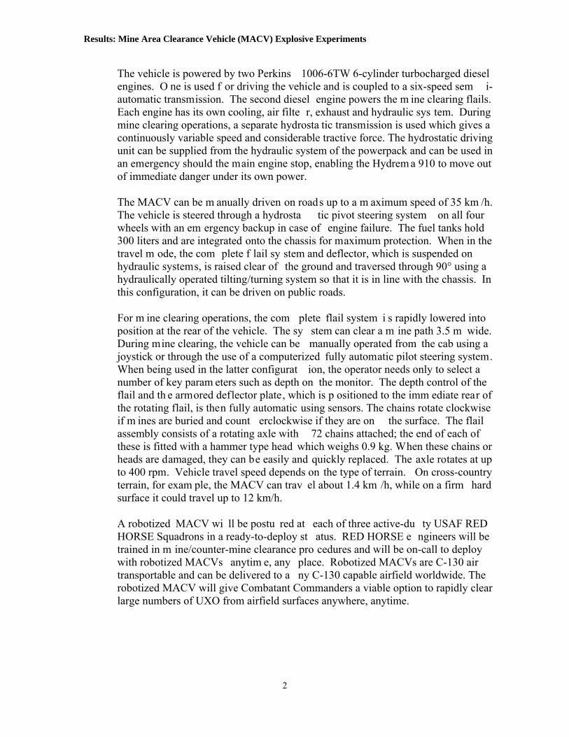
accelerometers and pressure gauges. Details on the gauges are shown in Figure 3 and summarized below:
o Accelerometer #1: Range = 200g. Located on left (as you face the flail) wall
panel of cab, where the robot ic low level controls we re located. Orientation was transverse to the ve hicle axis (i.e., left to right axis). N OTE: This gauge malfunctioned during the experiments and produced no useful data.
o Accelerometer #2: Range = 200 g. Located on left panel inside cab, near the video controllers. Orientation was along vehicle axis (i.e., front to back axis).
o Accelerometer #3: Range = 200 g. Located on horizontal surface left side, at video controllers. Orientation was vertical.
o Accelerometer #4: Range = 100 g. Located on right side of cab on high level controller tray. Orientation was ax ial and redu ndant with Accelerom eter #2 (i.e., front to back axis) for Experi ments 1 and 2. Orientation was then changed to transverse to the vehicle axis (i.e., left to right axis) for Experiments 3 and 4 to compensate for malfunctioning Accelerometer #1.
o Free Field Pressure Gauge #1: Range = 10 psi. Located on operators seat inside cab.
o Free Field Pressure Gauge #2: Range = 10 psi. Located on floor behind operator’s seat inside cab.
o Free Field Pressure Gauge #3: Range = 25 psi. Located in open test arena 31.5 feet from explosive device (same standoff as the MACV operator’s cab).
5.0 Experimental Results The four MACV experim ents were conduc ted on 8 July 2005 at AFRL’s Range 2, Tyndall AFB, FL. For each exp eriment, the vehicle w as stationary with the flail operating at a height th at just touched the grou nd surface. The exp losive charges were placed 3.5 feet horizon tal distance from the flail centerline, just beyond the radius of the flail hammers. Following the explosive de tonation, the flail was stopped and the MACV inspected for damage.
4
Results: Mine Area Clearance Vehicle (MACV) Explosive Experiments
Exp 1,2 Exp 3,4Operator’s Seat
Low Level Robotic Controls
High LevelRobotic Controls
GPS Control Panel
Video Controls1
2
34
2
1
Legend: Accelerometer or Accelerometer Axis Pressure Gauge2 2
Exp 1,2 Exp 3,4Operator’s Seat
Low Level Robotic Controls
High LevelRobotic Controls
GPS Control Panel
Video Controls1
2
34
2
1
Legend: Accelerometer or Accelerometer Axis Pressure Gauge2 2Legend: Accelerometer or Accelerometer Axis Pressure Gauge2 2
Figure 3. Instrumentation Inside Operator's Cab
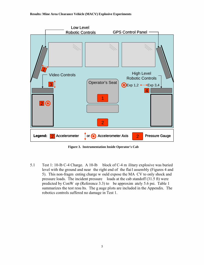
5.1 Test 1: 10-lb C-4 Charge. A 10-lb block of C-4 m ilitary explosive was buried
level with the ground and near the right end of the flai l assembly (Figures 4 and 5). This non-fragm enting charge w ould expose the MA CV to only shock and pressure loads. The incident pressure loads at the cab standoff (31.5 ft) were predicted by ConW ep (Reference 3.3) to be approxim ately 5.6 psi. Table 1 summarizes the test resu lts. The g auge plots are included in the Appendix. The robotics controls suffered no damage in Test 1.
5

Results: Mine Area Clearance Vehicle (MACV) Explosive Experiments
Figure 4. Pre-test: 10-lb C-4 Charge
Figure 5. Post-test: 10-lb C-4 Charge
Table 1. Test 1 Results
Gauge Description Measurement Accelerometer #1 Transverse No Data Accelerometer #2 Axial 2.1 g @ 18 ms Accelerometer #3 Vertical 3.0 g @ 18 ms Accelerometer #4 Axial 2.1 g @ 13 ms
Free Field #1 Inside Cab 0.08 psi @ 31 ms Free Field #2 Inside Cab 0.11 psi @ 26 ms Free Field #3 Arena 4.7 psi @ 19 ms
ConWep Prediction Arena Prediction 5.6 psi @ 16 ms Crater Diameter/Depth 6.5 ft diam / 14 in deep
6

Results: Mine Area Clearance Vehicle (MACV) Explosive Experiments
5.2 Test 2: M67 Frag Grenade. The M67 grenade is a spherical steel grenade
containing 0.13 lbs Comp B explosive. The grenade was buried level with the ground and near the center of the flail asse mbly (Figures 6 and 7). The incident pressure loads at the cab standoff (31.5 ft ) were predicted by ConWep (Reference 3.3) to be approximately 0.7 psi. Table 2 summarizes the test results. T he gauge plots are included in the Appendix. The robotics controls suffered no dam age in Test 2.
Figure 6. Pre-test: M67 Grenade
Figure 7. Post-test: M67 Grenade
7
Results: Mine Area Clearance Vehicle (MACV) Explosive Experiments
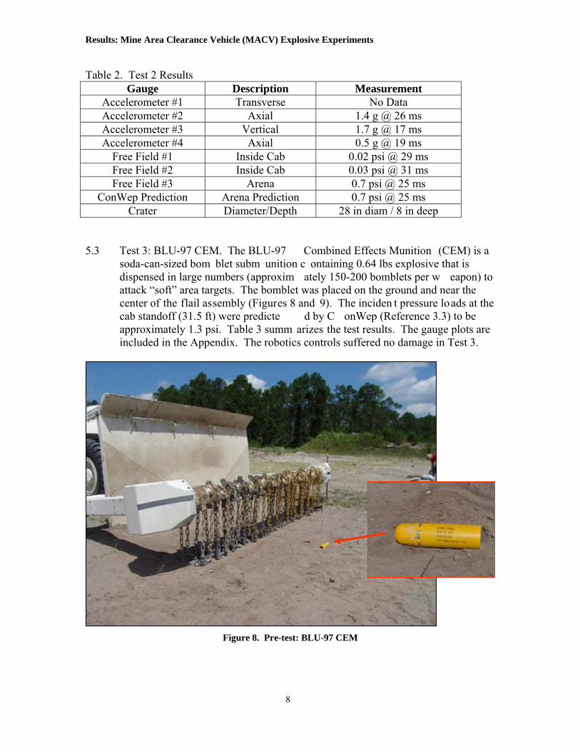
Table 2. Test 2 Results Gauge Description Measurement
Accelerometer #1 Transverse No Data Accelerometer #2 Axial 1.4 g @ 26 ms Accelerometer #3 Vertical 1.7 g @ 17 ms Accelerometer #4 Axial 0.5 g @ 19 ms
Free Field #1 Inside Cab 0.02 psi @ 29 ms Free Field #2 Inside Cab 0.03 psi @ 31 ms Free Field #3 Arena 0.7 psi @ 25 ms
ConWep Prediction Arena Prediction 0.7 psi @ 25 ms Crater Diameter/Depth 28 in diam / 8 in deep
5.3 Test 3: BLU-97 CEM. The BLU-97 Combined Effects Munition (CEM) is a
soda-can-sized bom blet subm unition c ontaining 0.64 lbs explosive that is dispensed in large numbers (approxim ately 150-200 bomblets per w eapon) to attack “soft” area targets. The bomblet was placed on the ground and near the center of the flail assembly (Figures 8 and 9). The inciden t pressure loads at the cab standoff (31.5 ft) were predicte d by C onWep (Reference 3.3) to be approximately 1.3 psi. Table 3 summ arizes the test results. The gauge plots are included in the Appendix. The robotics controls suffered no damage in Test 3.
Figure 8. Pre-test: BLU-97 CEM
8

Results: Mine Area Clearance Vehicle (MACV) Explosive Experiments
Figure 9. Post-test: BLU-97 CEM
Table 3. Test 3 Results
Gauge Description Measurement Accelerometer #1 Transverse No Data Accelerometer #2 Axial 0.6 g @ 24 ms Accelerometer #3 Vertical 0.6 g @ 17 ms Accelerometer #4 Transverse 0.9 g @ 17 ms
Free Field #1 Inside Cab 0.02 psi @ 29 ms Free Field #2 Inside Cab 0.03 psi @ 31 ms Free Field #3 Arena 0.9 psi @ 23 ms
ConWep Prediction Arena Prediction 1.3 psi @ 23 ms Crater Diameter/Depth 39 in diam / 15 in deep
5.4 Test 4: M15 Mine. The M15 Mine is an antitank mine that is contained in a round
sheet-steel casing containing approxim ately 22.75 lbs Comp B explosive. The mine was buried level with the ground su rface and near the center of the flail assembly (Figures 10 and 11). The incide nt pressure loads at the cab standoff (31.5 ft) were predicted by ConW ep (Reference 3.3) to be approxim ately 9.1 psi. Table 4 summarizes the test res ults. The gauge plots are included in the Appendix. The robotics controls suffered no damage in Test 4.
9

Results: Mine Area Clearance Vehicle (MACV) Explosive Experiments
Figure 10. Pre-test: M15 Mine
Figure 11. Post-test: M15 Mine
10

Results: Mine Area Clearance Vehicle (MACV) Explosive Experiments
Table 4. Test 4 Results Description Measurement Gauge
Acce r #1 leromete Transverse No Data Accelerometer #2 Axial 2.7 g @ 17 ms Accelerometer #3 Vertical 8.7 g @ 17 ms Accelerometer #4 Transverse 6.3 g @ 18 ms
Free Field #1 Inside Cab 0 .11 psi @ 29 msFree Field #2 Inside Cab 0.17 psi @ 26 ms Free Field #3 Arena 5.5 psi @ 19 ms
Co n Arena Prediction nWep Predictio 9.1 psi @ 14 ms Crater Diameter/Depth 9 p ft diam / 28 in dee
.0 Discussion
he Mine Area Clearance Vehicle was exposed to a range of munitions, including blast
ment
igure 12 summarizes the blast pressures measured in the four experiments. Except for
6 Tand fragment-producing weapons. The only damage noted from any of the four experiments was a vent cover knocked loose in the operator’s cab, and a few fragnicks on the deflector shield next to the flail mechanism. The vehicle remained fully operational, including the robotic controls, throughout the test series. Fthe M67 Grenade (Test 2), the measured free field (incident) pressures tended to be only 60 to 73% of predicted. Nevertheless, in all cases the increase in cab pressure was minimal, well below any pressure increase that would cause even temporary hearingproblems for people or damage to equipment.
10#
C-4
M67
Gre
nade
BLU-
97 C
EM
M15
Mine
Cab Interior Pressure
Free Field Pressure @ Cab Standoff
ConWep Prediction for Free Field
0.001.002.003.004.005.006.007.008.009.00
10.00
Pres
sure
(psi
)
Figure 12. MACV Pressure Measurements
11
Results: Mine Area Clearance Vehicle (MACV) Explosive Experiments
10#
C-4
M67
Gre
nade
BLU-
97 C
EM
M15
Mine
Axial Accelerometer 2Axial Accelerometer 4
Vertical Accelerometer 3Transverse Accelerometer 4
0.01.02.03.04.05.06.07.08.09.0
g's
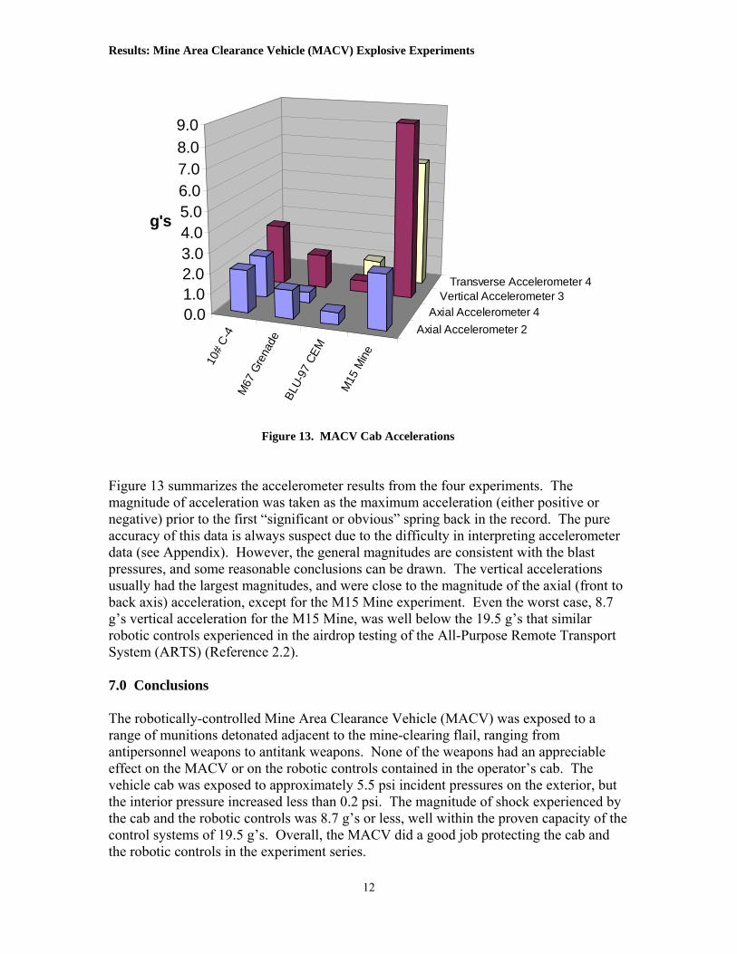
Figure 13. MACV Cab Accelerations
Figure 13 summarizes the accelerometer results from the four experiments. The or
r
to
ort
.0 Conclusions
he robotically-controlled Mine Area Clearance Vehicle (MACV) was exposed to a
ciable
but
the robotic controls in the experiment series.
magnitude of acceleration was taken as the maximum acceleration (either positivenegative) prior to the first “significant or obvious” spring back in the record. The pureaccuracy of this data is always suspect due to the difficulty in interpreting accelerometedata (see Appendix). However, the general magnitudes are consistent with the blast pressures, and some reasonable conclusions can be drawn. The vertical accelerationsusually had the largest magnitudes, and were close to the magnitude of the axial (frontback axis) acceleration, except for the M15 Mine experiment. Even the worst case, 8.7 g’s vertical acceleration for the M15 Mine, was well below the 19.5 g’s that similar robotic controls experienced in the airdrop testing of the All-Purpose Remote TranspSystem (ARTS) (Reference 2.2). 7 Trange of munitions detonated adjacent to the mine-clearing flail, ranging from antipersonnel weapons to antitank weapons. None of the weapons had an appreeffect on the MACV or on the robotic controls contained in the operator’s cab. The vehicle cab was exposed to approximately 5.5 psi incident pressures on the exterior, the interior pressure increased less than 0.2 psi. The magnitude of shock experienced by the cab and the robotic controls was 8.7 g’s or less, well within the proven capacity of thecontrol systems of 19.5 g’s. Overall, the MACV did a good job protecting the cab and
12

Results: Mine Area Clearance Vehicle (MACV) Explosive Experiments
Appendix: Data Graphs
13

MACV – Experiment 1 Gauge Malfunction
3.0 g @ 18 ms
2.1 g @ 18 ms 2.1 g @ 13 ms

Results: Mine Area Clearance Vehicle (MACV) Explosive Experiments
15
MACV – Experiment 1
0.08 psi @ 31 ms
0.11 psi @ 26 ms
4.7 psi @ 19 ms

Results: Mine Area Clearance Vehicle (MACV) Explosive Experiments
16
MACV – Experiment 2 Gauge Malfunction 1.7 g @ 17 ms
1.4 g @ 26 ms 0.5 g @ 19 ms

Results: Mine Area Clearance Vehicle (MACV) Explosive Experiments
MACV – Experiment 2
17
0.02 psi @ 29 ms
0.03 psi @ 31 ms
0.7 psi @ 25 ms

Results: Mine Area Clearance Vehicle (MACV) Explosive Experiments
18
MACV – Experiment 3 Gauge Malfunction
0.6 g @ 17
0.6 g @ 24 ms
ms
0.9 g @ 17 ms
Results: Mine Area Clearance Vehicle (MACV) Explosive Experiments
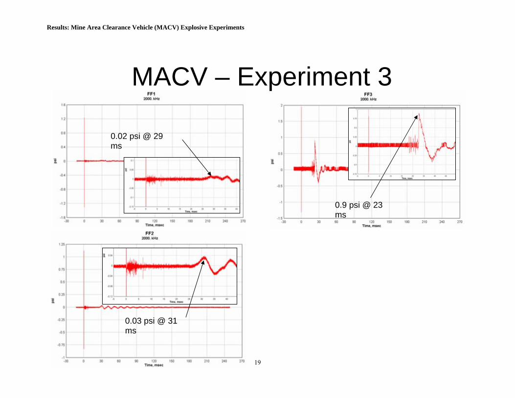
MACV – Experiment 3
19
0.0ms
0.03 psi @ 31 ms
2 psi @ 29
0.9 psi @ 23 ms

Results: Mine Area Clearance Vehicle (MACV) Explosive Experiments
20
MACV – Experiment 4
Gauge Malfunction
8.7 g @ 17 ms
2.7 g @ 17 ms
6.3 g @ 18 ms
Results: Mine Area Clearance Vehicle (MACV) Explosive Experiments
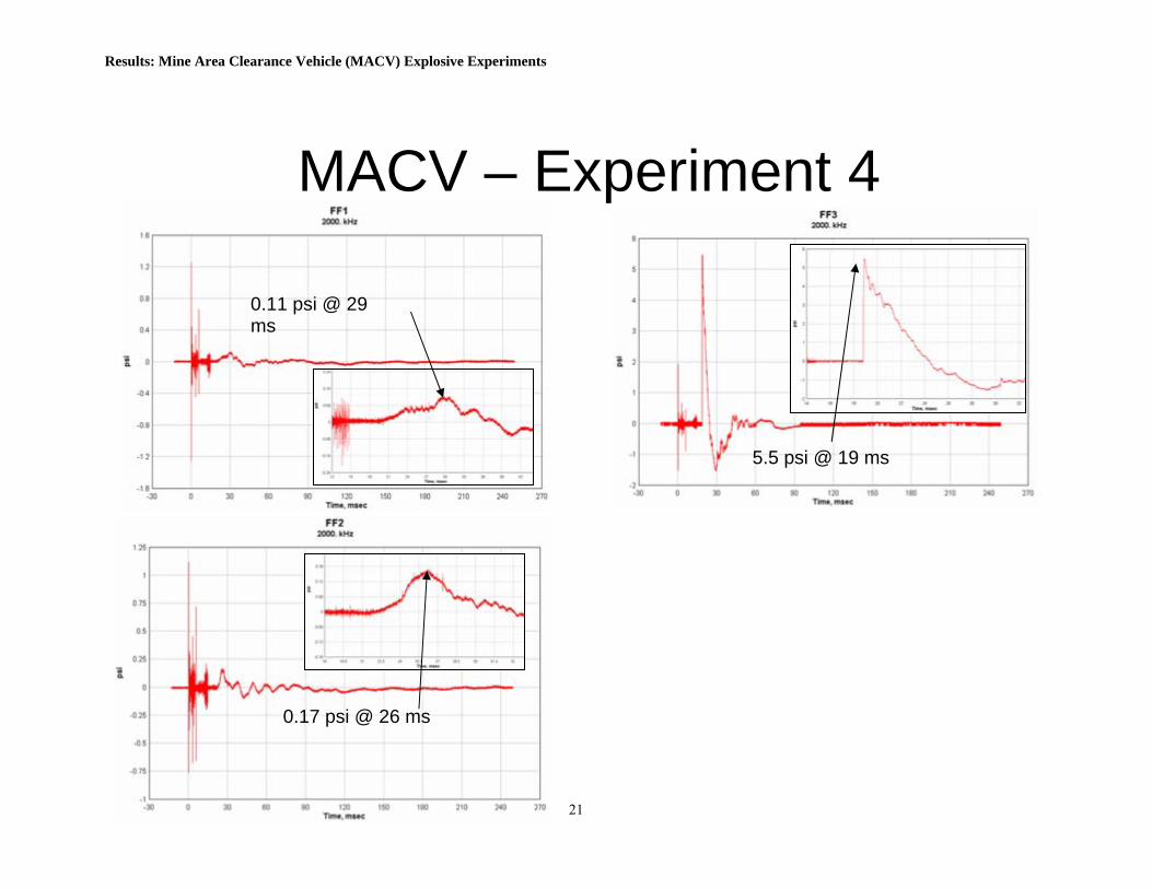
MACV – Experiment 4
21
0.11 psms
i @ 29
0.17 psi @ 26 ms
5.5 psi @ 19 ms