restructuring operations for data-flow diagrams · 1 folding 2 expanding 3 splitting 4 merging 5...
TRANSCRIPT

Restructuring operations for data-flow diagrams by Ming-Jie Chen and Chyan-Goei Chung
When defining and designing software with structured analysis and design methods, we need to restructure data-flow diagrams. Using basic editing operations to restructure large systems with voluminous data-flow diagrams is tedious, laborious and error-prone. It is necessary to have data-flow diagram editors that provide editing operations specific for restructuring. This paper proposes and formally specifies a set of operations sufficient for all restructuring needs. It also confirms that the properties of consistency and completeness are observed by all the restructuring operations, and that both models of data-flow diagrams are equivalent, before and after each of the restructuring operations.
1 Introduction
To increase engineer productivity and improve software quality, the software engineering community have made considerable research efforts towards creating better methods and tools. Structured ambsis and design methods [ 141 are widely used in defining and designing software. Among structured techniques, data-flow diagrams have been reported to be the most popular [5] and contribute the most favorably towards increasing productivity when computer-aided software engineering (CASE) technology is used in preference to manual methods [ 61. Not surprisingly, many CASE tools have been developed to help draw data- flow diagrams. Most of them support consistency analysis [7-101 and various complex drafting functions [&11], but none of them provide a set of editing operations sufficient for conveniently restructuring data-flow diagrams. In this paper, we investigate this problem and propose a set of editing operations sufficient for all restructuring needs.
1 .I
To accommodate large systems, structured analysis does not model a system in a single data-flow diagram as large as a football field, for example, but instead as multi-levelled data-flow diagrams. These diagrams form a strictly hierar-
The need for restructuring
chical structure, with composite processes defined in higher levels and their component processes defined in lower levels. At the top of the hierarchy is a single diagram called the context diagram, which contains only one process. The system is considered as partitioned from the process into all lower level diagrams, which we call transformation dia- grams. The levelled structure makes a system model easy to read and comprehend. However, the concept of levelling generates the necessity for restructuring. The main needs are listed below.
Restructuring for appropriate Partitioning. Levelled data-flow diagrams allow a top-down approach to analysis, which helps us build a system model of data-flow diagrams systematically in a top-down fashion. However, the approach does not guarantee that the resulting model is an appropriate partitioning. For example, the name of a com- posite process may not accurately reflect everything indi- cated by its name in the child diagram of the process; we have to break it apart, or distribute all or part of its work to other processes. Another candidate for restructuring is a data-flow diagram that turns out to consist of disconnected networks.
Restructuring to reduce complexity. We model a system as a levelled structure for readability. However, when many processes crowd a dataflow diagram in a system model, such readability is hindered; we have to split the diagram. Another important problem is interface complexity. It is a requirement that every dataflow diagram should have a fairly simple flow pattern. When the total number of flows in a diagram or the number of flows connected with a process is too large, we have to group some of the processes in the diagram together to push some flows down to a lower level.
Restructuring to present particular system aspects. Most errors found during testing and operation are traceable back to poor understanding or misinterpretation of users’ require- ments [ 121. Effective communication with users is therefore important. It is helpful to present the system model in various aspects, by restructuring the upper levels of the system model according to users’ interest. Useful aspects are grouping related responses, grouping processes whose inputs and outputs are connected to a terminator or related terminators, and grouping processes to declare the interface between man and machine.
Restructuring for function allocation. After completing the requirements phase, and before applying transform and transaction analyses [3, 41 to obtain structure charts from
Software Engineering Journal July 1991
-7
181

levelled dataflow diagrams, we have to restructure them around candidate processors (if multi-processor architecture is used) and then restructure those allocated to an individ- ual processor around candidate tasks (if multi-tasking soft- ware architecture is used for the processor). Of course, processor modelling and task modelling do more than restructuring of levelled data-flow diagrams. Nevertheless, except for the identification of processors and tasks, func- tion allocation through restructuring is the earliest stage of the design phase.
None of the above-mentioned restructuring needs are our invention. They are found in various works by DeMarco [ l] , Ward and Mellor [13, 141, Hatley and Pirbhai [15], and Yourdon [16], where many convincing cases requiring restructuring can be found. We only summarise the needs here for the convenience of readers.
1.2 Requirements of restructuring operations
Certainly, we can use basic editing operations, such as inserting/deleting elements, connecting/disconnecting ele- ments, and creating/removing diagrams, to accomplish restructuring. However, this approach is tedious, laborious and error-prone. Problems of inconsistency and incomplete- ness may creep in. It is not easy to keep levelled data-flow diagrams in balance after restructuring. It is more difficult to guarantee that both system models are equivalent, before and after restructuring. These problems become serious for large systems with voluminous data-flow diagrams. There- fore, we need data-flow diagrams editors that provide spe- cific operations for restructuring. An eligible set of restructuring operations must meet the following three requirements.
0 Both system models of levelled data-flow diagrams must be equivalent, before and after evey, restructuring oberation in the set. The structuring of a system model into levelled diagrams is for ease of reading and comprehension. Composite processes in upper levels are only bookkeeping entities, representing ways of keeping track of connected sets of lower level processes. Thus, any restructuring oper- ation must not change the underlying network of primitive processes. 0 Evey, restructuring operation in the set must maintain the system model properties of consistency and completeness. Restructuring is performed in those phases after a system model is completed and passes consistency and complete- ness analysis. Thus, the system model to be restructured is consistent and complete. Any restructuring operation must not break down the properties. 0 The set of restructuring operations must meet the restructuring needs stated earlier. As restructuring oper- ations are used to automate laborious manual operations, any operation which meets some of the restructuring needs must be provided by one, or a simple combination, of the operations in the set. However, for users’ convenience, it is not necessary to reduce them to a minimal set.
We have created such a set of restructuring operations. They have been formally specified and validated to meet all requirements. The formal specification and the validation are represented later in this paper.
2 Specification of restructuring operations
In this Section, we propose an eligible set of restructuring operations, define a formal notation based on the set, rela- tion, and first-order logic theories [17], and then use the notation to specify the operations.
2.1 An eligible set of restructuring operations
To meet all the restructuring needs mentioned above, we must have editing operations for grouping processes into composite processes (folding), for replacing composite pro- cesses with their component processes (expanding), for split- ting composite processes and splitting data-flow diagrams (splitting), for merging composite processes and merging data-flow diagrams (merging), and for moving processes from their residing data-flow diagrams to other diagrams (transferring). Therefore, we have at least five restructuring operations, including folding, expanding, splitting, merging and transferring. The five operations are sufficient for all the restructuring needs and are discussed below. A sche- matic illustration is shown in Fig. 1.
0 Folding: groups a set of processes residing in the same data-flow diagram into a composite process, creates a child diagram for the composite process, and puts the set of pro- cesses, data flows and data stores linked with these pro- cesses, and their connections into the child diagram. This operation increases a system model of levelled data-flow diagrams by one level. 0 Expanding: replaces a composite process in its residing diagram, with all the elements and their interconnected network in its child diagram. This operation decreases a system model by one level. 0 Splitting: splits a composite process and its child diagram into two composite processes and two diagrams, with each new composite process being either of the two new diagrams. 0 Merging: merges two composite processes in the same diagram into one composite process, merges their child diagram into one diagram, and makes the new diagram become the child diagram of the new composite process. 0 Transferring: transfers a process from its current residing diagram into another. Of course, we cannot transfer the only process in the context diagram to another diagram; we do not allow another process to be transferred to the context diagram. Besides, we cannot transfer any process to any diagram decomposed directly or indirectly from the process ; otherwise, cyclic decomposition sequences will be introduced into the system model.
2.2 The notation
We shall specify each operation as an editing operator. Before the specification, we describe below the notation used, including a formal definition of the structures of data- flow diagrams and system models of levelled data-flow dia- grams, and a formula for expressing restructuring operators.
2.2.1 Data-flow diagram structures: following DeMarco’s structured analysis [ l ] , we use four kinds of elements (i.e. processes, terminators, flows, and stores) and connections
182 Software Engineering Journal July 1991

1 folding 2 expanding
3 splitting 4 merging
5 transferring
Fig. 1 Schematic illustration of restructuring operations
between the elements to build a data-flow diagram. Thus, we have
Definition I
A data-flow diagram (structure) is a five-tuple (P, T F, S, C), where P, T, F and S are sets of processes, terminators, flows and stores, respectively, and C s [ ( P U T) x (F U S ) ] U [(F U S ) x (P U 771 is a connection relation.
An initially created dataflow diagram will be (0, 0, 0, 0, 0). In this definition, we assume that every element is given a label when created and it will be referred to by its label afterwards. For simplicity, we do not introduce a label- ling function for the definition. When we talk about the equivalence of two processes, such as p1 = p2 and pl # p2, we mean whether they have the Same label, such as
Software Engineering Journal July 1991
Label(p1) = Label(p2) and Label(p1) # Label(p2). Similar conventions are applied to terminators, flows and stores.
For a data-flow diagram structure x, we use the notations x.P, x.T, x.F, x.S and x.C to refer to its five components. To shorten expressions, we define X. Y as Ux E x. Y, where X is a set of data-flow diagrams and Y can be P, T, F, S or C. We also define four functions for obtaining the flow inputs, flow outputs, store inputs and store outputs of pro- cesses and terminators.
Definition 2
For a process or terminator e, in its residing data-flow diagram x , and for a set of processes and terminators E, a flow input function Fi(J a flow output function Fe(-), a stcore input function 9(-) and a store output function So(-) are defined as follows:
183

cash-order credible-order
order
credit-order
credit-info X
rejected-order
b C
Y = (P, r. F. s, c) F'(CLASSIFY-ORDER) = {order} f O(CLASSIFY-0RDER) = {cash-order, creditorder} S'(CLASSIFY-ORDER) = 0 SO(CLASSIFY-ORDER = 0
P = {CLASSIFY-ORDER. VERIFY-CREDIT}
T = 0 F = {order, cash-order, credit-order, credible-order,
S = {credit-info} C = {<order, CLASSIFY-ORDER), <CLASSIFY-ORDER,
cash-order), (CLASSIFY-ORDER, credit-order), (creditorder. VERIW-CREDIT). (credit-info. VERIFY-CREDIT). <VERIFY-CREDIT, credibile-order). <VERIFY-CREDIT. rejected-order)}
rejected-order} F'(VERIFY-CREDIT) = {credit-order} Fo(VERIFY-CREDIT) = {credible-order, rejected-order} S'(VERIFY-CREDIT) = {credit-info} S'(VERIFY-CREDIT) = 0
Fig. 2 n A sample transformation diagram b Definition of the diagram's structure c The flowistore input/output functions
Illustration of the data-flow diagram structure and the flowlstore inputloutput functions
F(e) = {f E xEl cf, e ) E x.C for some e E x.P U x.T}
F(e) = {f E xPI (e , f ) E x.C for some e E x.P U x.T} .!?(e) = {s E x.SI (s, e ) E x.C for some e E x.P U x.T}
F(e) = {s E x.S I ( e , s) E x.C for some e E x.P U x.T}
P(E) = U , , , P ( e )
F " 0 = U e , E F " ( 4 90 = U. E E S (e )
s"(E) = U . t E .%)
Context diagrams and transformation diagrams are special data-flow diagrams. The same structural format as the data- flow diagram structure is used to represent context dia- grams and transfomtion diagrams. A sample transformation diagram is given in Fig. 2 to familiarise readers with the notations and functions.
2.2.2 System mod&: We model a system as a levelled structure of data-flow diagrams, where the top one is a context diagram and all lower level diagrams are
184
transformation diagrams. Thus, we can define a system model as a context diagram, a set of transformation dia- grams, and a mapping between these transformation dia- grams and their parent processes.
Definition 3
A system model is a three-tuple (cd, X , D), where cd is a context diagram, X is a set of transformation diagrams and D E P x X is a decomposition relation, with P = CdP U X.P.
An initially created system model will be ((0, 0, 0, 0, a), 0, 0). For a system model m, we use the notations m .cd, m .X and m .D to refer to its three components, and the notations m.P, m.T, m.F, m.S and m.C to refer to the sets of all processes, terminators, flows, stores, and their connections in it, i.e. m.P = m.cd.P U m.X.P, m.T = m.cd.T, m.F = m.cd.F U m.X.F, m.S = mX.S and m.C = m.cd.C U m.X.C.
For every ( p , x ) in m.D, we use the function x.pa to refer to the parent process p of the diagram x, and the func-
Software Engineering Journal July 1991

tion p.kid to refer to the child diagram x of the process p . If p does not exist in m.P such that ( p , x ) is in m.D, the function xpa is undefined. If x does not exist in m.X such that (p, x) is in m.D, the functionp.kid is undefined.
2.2.3 Formula for expressing restructuring operators: before restructuring, we must make sure that such a process is allowed. Thus, a formula for expressing restructuring operators consists of a prerequisite and some editing actions. An operator is specified as
operator-name(parameter1, parameter2, . . .) = =
require a-prerequisite perform
editing-action-1 editing-action-2 ...
end
An editing action changes the structure of a system model or one of the data-flow diagram structures in the model. We use the notation \ t o specify the structure to change and the structure after change, and use the key word where to indicate a newly created data-flow diagram structure if required. An editing action is specified as
the-structure-to-change \ the-structure-after-chanRe, [where specifcation-ofa-newlycreated data-
flow-diagram-structure] ;
We also use the keyword then to force a list of editing actions to be taken one after another. For simplicity we allow recursive definition, and for flexibility we allow an action to he conditional and existentially or universally quantified, such as
condition =. an-action (Ix)(condition s an-action) (VxXcondition * an-action)
2.3 Specification of the restructuring operators
Now, we specify the five restructuring operators with the notations. To ease understanding, naming of parameters and variables in the specification is shown in Fig. 3. The specification only shows what changes each of the operators will make to the addressed system model; no implementa- tions are indicated. The expression for each of the Fis and S,s in the specification can be reformulated in many other ways. For brevity, for a process (or a set of processes) ter- minators and all other processes that are not in the dia- grams directly or indirectly decomposed from the process (the set of processes) are called the externals of the process (the set of processes); the flows and stores that are con- nected both with the process (the set of processes) and with the externals of the process (the set of processes) are called the interfacing flows and stores of the process (the set of processes); and the connections between the interfacing
1 fold (m. x, R, p) 2 expand (m. x, p)
x.pa
X X
4 merge (m. x. p, q)
Fig. 3 Naming of parameters and variables in the specification of restructuring operators
Software Engineering Journal July 1991
I
185

I
5.2 lower (m. x. p. vj
5.1 raise (m, x, p, yl
V V
5.3 transfer (m, x, p, yl
xo = vo xo = yo
Fig. 3 (continued) Naming of parameters and variables in the specification of restructuring .operators
flows and stores and the process (the set of processes) are called the interfacing connech'om with the process (the set of processes). In addition, note that we inhibit any restructuring operator from making changes to the context diagram in a system model.
2.3.1 Thefold operator: it groups a set of processes (R), in a transformation diagram (x ) in a system model (m), into a composite process (p). The flows and stores that are only connected internally with the processes in the set are all removed from the diagram. All the connections with the processes are also removed, but the original interfacing con- nections with the set of processes become the interfacing connections with the composite process. The operator also creates a diagram (y) as the child diagram of the process (p)
for accommodating the set of processes (R) and their orig- inal connected flows, connected stores and connections.
fold(m, x, R, p) = = require (x E m.X) A (R c x.P) A (R # a) perform
x.c U
A (R # x.P) A (p $ m.P)
x \ (x.P U {p} - R, x.T, x.F - F3, x.S - S3, U SI) x (PI1 U [{PI
x (F2 U S2)] - C1) m \ (m.cd, m.X U {y}, m.D U {(p, y>}b
where y = (I?, 0, F4, S4, Cl) end
where
F1 = F'(R) - P(R)
186 Software Engineering Journal July 1991
1

F2 = F(R) - F‘(R) F3 = F’(R) n F(R) F4 = F’(R) U F(R) S1 = S‘(R) n [S’(x.P - R) U s”(x.P - R) U S’(x.pa)] S2 = S”(R) n [s’(x.P - R) U S”(x.P - R) U S”(x.pa)] S3 = [s’(R) U S”(R)] ~ [S’(x.P - R)
S4 = S(R) U SO(R) c1 = U l e R [ ( W U s’(r)) x {.}I U [ { r } x (F”(r) U s”(4)l
U sO(x.P - R) U S’(x.pa) U S”(x.pa)]
2.3.2 The expand operator: it replaces a composite process (p) , in its residing diagram (x) in a system model (m), with the contents of its child diagram (p.kzd). The inter- facing connections with the process are removed from its residing diagram. The process’ child diagram and the decomposition relationship between the process and its child diagram are removed from the system model.
expand(m, x, p ) = =
require (x E m.X) A ( p E x.P)
perform A (32 E m.XX(p, z ) E m.D)
~ \ ( x . P ~ p . k i d . P - { p } , ~ . T ~ p . k i d . T , ~ . F U F1, x.S U 5’1,
m \ (m.cd, m.X - {p.kzd}, m.D - { ( p , @.kid)}) x.c U p.kf4i.c - C1)
end
where
F l = p.kid.F - [F’(p) U F(p)]
C1 = C(F‘(P) U S’(P)) x { P I 1 U [ { P } S = p.kid.S - [s’(p) U s”(p)]
x (F“(P) U SYP)) l
23.3 The split operator: it splits a composite process (p), in a transformation diagram (x ) in a system model (m), into two composite processes ( p and q) by s e p a t i n g a set of processes (R) in its child diagram (p.kzd) into a newly created diagram Cy). The flows and stores that are con- nected both with the set of processes and with the other processes in the child diagram (p.kld), but not with the com- posite process (p), are added to the transformation diagram. The interfacing connections with the set of processes become the interfacing connections with the newly created composite process. The interfacing connections with the other processes in the child diagram are added to the inter- facing connections with the original composite process, if they were not originally with it. However, the interfacing connections that are with the original composite process but not with the other processes in the child diagram, other than the set of processes, are removed from the transform- ation diagram. The newly created diagram becomes the child diagram of the newly created composite process (9). The operator adds all the connected flows, connected stores and connections with the set of processes to the newly created diagram.
split(m, x, p , R, q) = =
require (x E m.X) A ( p E x.P) A (32 E m.X)(@, z> E m.D) A (R cp.kid.P)
A (R # 0) A (R #p.kid.P) A (q E# m.P)
x \ (x.P U { q } , x.T, x.F U F1 U F2, x.S U (SI U S2), x.C U [(F3 U S3) x { a ) ] U [ { q } x (F4 U S4)]
perform
Software Engineering Journal July 1991
U [ (Fl U SI) x {PI1
- [ { P } x (E U SQl) U [{PI x (F2 U sa1 - [(F5 U S5) x {PI1
p.kid \ (p.kid.P - R, p.kid.T, p.kid.F - F7, p.kid.S - S7, p.kid.C - C1)
m \ (m.cd, mX U { Y } , m.D U ( (4 , Y > } X where y = (R, $3, F8, S8, C1)
end
where
F1 = F’(p.kid.P - R) n F”(R) F2 = F”(p.kid.P - R) n F’(R) F3 = F’(R) - F(R) F4 = P(R) - F’(R) F5 = F’(p) n F’(R) F6 = P(p) n F(R) F7 = [F’(R) U F(R)] - F1 - FZ F8 = F’(R) U P(R) S1 = [S‘(p.kid.P - R) - s’(p)] n [S‘(R) U s”(R)I S2 = [S”(p.kid.P - R) - .Y(p)] n [S’(R) U s”(R)] S3 = S’(R) n [ S’(p.kid.P - R) U S”(p.kid.P - R) U Si())] S4 = S”(R) n [ S’(p.kidP - R) U S”(p.kid.P - R) U S”(p)] S5 = Si@) - S’(p.kid.P - R) S6 = s”(p) - S”(p.kzd.P - R) S7 = [S’(R) U S”(R)] - [s’(p.kid.P - R)
U S”(P.kld.P - R)] S8 = 9(R) U F(R)
C1 = UrtR[(Fi(r) U S’(r)) x { r } I U [ { r } x (F(d U S W l 2.3.4 The merge operator: it merges two composite pro- cesses ( p and q) , in the same diagram ( x ) in a system model (m), into one composite process (p). The flows and stores that are only connected internally with the two processes, and the connections between the remaining process ( p ) and these flows and stores are all removed from the diagram. All the connections with the removed process (4) are also removed, but those connections that are between the removed process and the extemals of the two composite processes are added to the interfacing connections with the remaining process, if they were not originally with it. The operator also merges the child diagrams of the two compos- ite processes (p.kid and q.kid) into one diagram @.kid). The other diagram (q.kzd) and its decomposition relationship with the removed process are both removed from the system model.
merge(m, x , p, q) = = require (x E m.X) A (p , q E x.P) A ( P # q)
perform A ( 3 ~ . z E m.XX(P. Y ) . (q, 2 ) E m.0
x \ (x.P - {q } , x.T, xE - F1 - F2, x.S ~ (S1 U S2), x.C U [(F3 U S3) x {P}]
U [ { p } x (F4 U S4)] - C1 - [ (Fl U S1) x {PI1 - [ { P I x (FZ U S a l )
p.kid \ (p.kzd.P U q.kid.P, p.kid.T U q.M.T, p.kid.F U F5, p.kid.S U S5,
p.kid.C U 9.kid.C) m \ (m.cd, m.X - {q.kid}, m.D - { ( q , 9.kid)})
end where
F1 = F’(p) n P(q) F2 = F(p) n F‘(9)
187

I
F3 = P(q) - PO) F4 = F(q) - F’(p) F5 = q.kd.F - F1- F2 s 1 = S’(P) - [S(x.P - {p, 4 ) ) U s”(x.P - { p , q } )
s2 = Y(P) - [S ’ (xS - {p, 4) ) U s”(x.P - { p , q } )
s3 = [s’(q) - s’(p)] n [s‘(x.P - {A q } ) U P(x.P
U S‘(x.pa)]
U P(x$a)]
- { P , 4)) U S’(x.Pdl
- {A 41) U S”(X.PQ)l S4 = [s”(q) - SO(p)] n [S’(x.P - {p , q } ) U S”(x.P
S5 = p.kzd.S - [(S’(p) U s’(p)) n (s’(q) U s”(q))l
c1 = [(F’(q) U S’(4)) x {4}1 U [ { q } x (F”(q) U s”m1
2.3.5 The transfer operator: it transfers a process (p), from its residing diagram (x) in a system model (m), into another diagram (y). To specify the operator clearly, we use two more primitive operators: the raise operator, which moves a process (p) from its residing diagram (x) one level up to the diagram (y), in which its parent process (xpa) resides; and the lower operator, which moves a process ( p ) from its residing diagram (n) one level down to the child diagram Cy) of one of its sibling processes (y.pa). To Save space, detailed descriptions of these three operators are omitted.
raise@, x, p , y) = = require (x, y E m . 3 A (x.pa E y.P) A ( p E xP)
perform A ({PI #X.P)
y \ Cy.P U { p } , y.T,y.F U F1 U F2, y.S U (Sl U S2) y.c U c1 U [(Fl U Sl) x {x.pa}]
U [ {x.pa} x (F2 U S2)] - [ (F3 U S3) x pa}] - [ { x . ~ Q } x (F4
U W1) x \ (x.P - {p}, x.T, x.F - F3 - F4, x.S - S5, x.C - C1)
end
where
F1 = F’(x.P - { p } ) n P(p) F2 = P(x.P - { p } ) n P(p) F3 = F’(x.pa) n P(p) F4 = P(x .pu) n P(D) S1 = [ S‘(x.P - {p} ) - S’(x.pa)] n [ s’(p) U So(p)] S2 = [s”(x.P - { p } ) - S”(x.pa)] n [S’(p) U s”(p)l s3 = S’(x.pa) - s’(x.P - {p} ) s 4 = P(x.pa) - s”(x.P - { p } ) s5 = [S’(P) U s”(P)] - [s’(x.P - {p} ) U s”(x.P - {P})] c1 = [(P(P) U S”) x {P}l U [{PI x (PM U P(P))l
lowexfm, x, p, y) = = require (x, y E m.X) A Cy.@ E n.P) A ( p E x.P)
perform A ( P #Y.PU)
x.c U [ (F3 U S3) x { y p a ) 1 U [ {y.pa} x (F4 U S4) 3 - c1 - [(Fl U S1) x {y.Pu}] - [{y.pa} x (F2
x \ (x.P - (p}, x.T, x.F - F1 - F2, x.S - (S1 U S2),
U
y \Cy.P U @},y.T,y.F U F3 U F4,y.S U S5,y.C U C1)
end
F1 = P(y.pa) n P ( p ) where
F2 = PCy.@) n F‘(p)
F3 = F’(p) - F“(y.pa) F4 = P ( p ) - F’Cy.Da) s1 = S’(y.pa) - [Si(x.S - {y& p } ,
s2 = P(y.pa) - [ S’(x.S - {y.pa, p } ,
s3 = [ - S’Cy.pa)] n [ S’(x.P - {y& p } )
S4 = [ s”(p) - S”(y.pa)] n [ s’(x.P - {y.pa, p } )
s5 = [s’(P) U so(P)I - [S ’ ( yPU) U S~(Y.pa)l c1 = [(F” U s’(P)) x {PI1 U [ {PI x (F”(P) U s”W1
U S”(x.S - {Y.PU, P}) U s’(x.pu)l
U SO(x.S - {y& p } ) U s’(x.pa)l
U s”(x.P - {y.pa, p } , U S’(x.pa)l
U s”(n.P - {y& p } ) U S”(x.pa)l
transfexfm, x, p. y) = =
require(x,ysm.X) A ( x f y ) A ( p ~ x . P ) A ({p} #x.P) A 1 ( 3 o , P o , Y i , . . . ,Dn-i,YJ[(l < n ) A ( P o = P )
(Po E Y O , ~ A ... A ( # “ - I ~Y.-IJ‘) A ((Po,Yi>, A Cyo=x) A Cy,=Y) A
. . . . 0“- YJ E m.Q1 perform
(2x07 90 , Xlr ..., qk-1, xk)[(l f k) A (x0 = Y ) A (xk = x ) A (qo E xo .P)
A “ ’ A (qk-1 f x k - l p ) A ( < q O ? x , ) , ( q k - 1, xk> E m.D) - raise@, x, , p, xk - I ) then . . .
then raise(m, xl, p , xo)]
(3Y0, P O ? YI. ...* P”- l , Y,)[(l f 4 A Cy, = -4
A . ’ . A @ . - I EY,-~J’) A (<Po,Yi>, ..., A Cyn =U) A (Po EY0.P)
(P , - l , Y J E m.D)
then lower(m, Y.- P , Y J I lowerim, yo, pB yl ) then . . .
( 3 x O ! q 0 , x 1 , ..., ~ k - 1 ~ x k ) ( 2 Y , , p , , Y l ,...,p,-l,Y,) [(I f 4 A (1 < a) A b o =YO) A (40 f Po)
A (xk A CVn = Y ) A (qOEX0-P) A ” ’ A (qk-1 Exk-1.P) A @ o E Y w P )
A . . . A EY.-~.P) A ((SO, XI>! ..., (qk-l,xk>, (PO,Yl), ...,
0- I , Y.> E m . 0
ruise(m, xlr p , xo) then
lowerim. Y.- I , P, Y J I
* ruise(m, x k , p , xk I ) then . . . then
lower(m, yo, p, yl) then . . . then
end
3 Validation of the restructuring operators
In this Section we formally define the meaning of consis- tency and completeness, and the equivalence of system models. We also confirm that the properties of consistency and completeness are observed by all the restructuring operations, and that both system models are equivalent, before and after each of the restructuring operations.
3.1 Definition of consistency and completeness
The structure of a system model, context diagram and transformation diagram must be consistent and complete, and regulated by a set of conventions called formation rules. These rules include ways of forming a system model from data-flow diagrams, of forming a context diagram from basic elements and of forming a transformation diagram from basic elements. They also include the bal-
188 Software Engineering Journal July 1991

ancing (i.e. the equivalence of flows and stores and the con- sistency of their connections) between composite processes and their child transformation diagrams, the originality of elements (labels) over all the diagrams in a system model, and the accessibility of processes to the externals.
We formally define a formation rule as a well formed formula [17]. For example, we define the rule inhibiting any transformation diagram with more than one parent process as
(Vx E m.XWVp, q E m.P)[(@, x ) , < a x > E m . 0 = ( P = d 1 In this formula, the symbol - denotes ‘implies’ and the letter m refers to any system model. We also use set connec- tives to express well formed formulas concisely. For example, the rule only allowing flows and stores to be con- nected with processes in a transformation diagram can be defined in the following formula.
x.c G [(x.F U n.S) x x.PI U [x .P x (x.F U x.S)I
In this formula, the symol E denotes ‘is a subset of and the letter x refers to any transformation diagram.
A typical set of commonly used formation rules is described and formally defined in Appendix 1. When a system model structurally conforms to all of the formation rules, it is structurally consistent and complete.
3.2 Definition of equivalence of system models
What we are really concerned a b u t in a system model are primitive processes and their interfaces, through data flows and stores, with one another and with terminators. The structuring of a system model into levelled dataflow dia- grams is only to ease understanding. In a structurally con- sistent and complete system model, every composite process can be completely replaced by the contents of its child diagram. We can repeatedly apply the replacement process to a system model until a single data-flow diagram, consist- ing only of primitive processes, terminators, flows, stores and their connections, is obtained. We call the single data- flow diagram the intrinsic model of the system model and define two system models as equivalent if they have the same intrinsic model.
Definition 4
For a structurally consistent and complete system model m, its intrinsic model is a data-flow diagram structure (P, m.T, m.F, m.S, C), where
P = {p E m P i ( 3 z E m . a @ , z ) E m B ) }
= u,em.JF’(t) x { t } ) U ( i t } x W t ) )
U U,,,[(F’(P) U Si@)) x {PI1 U U P } x (F”(P)
U S ( P ) ) l Definition 5
Two structurally consistent and complete system models are equivalent if, and only if, they have the same intrinsic model.
3.3 The validation
Since the validation for all the restructuring operators is
Software Engineering Journal July 1991
similar, we only show the validation of the fold operator here. Recall that the fold operator groups a set of processes (R), in a transformation diagram (x) in a system model (m), into a composite process (p), and it also creates a diagram Cy) as the child diagram of the process (p), for accommcdat- ing the set of processes (R) and their connected flows and stores. We refer to the system model after the operation as m’ and the transformation diagram changed from x as x’.
To confirm that the foM operator observes the properties of consistency and completeness is to show that the system model after folding (m’) conforms to all the formation rules, on the condition that the system model up to fold (m) con- forms to all the formation rules. The conformity of the system model m’ to each of the formation rules is shown in Appendix 2.
To demonstrate that the two system models m‘ and m are equivalent, we must show that the five components in their intrinsic models are equivalent.
0 From the specification of foM, we have m‘.cd = m.cd, m’.X = ( m X - { x } ) U {x’ , y } , x’.P = x.P U { p } - R, and y.P = R. Thus, we have x’.P U y.P = x.P U {p}. We then have m’.X.P=(m.X.P-x.P)u(x‘.Puy.P)=(m.X.P- x.P) U (x.P U { p } ) = m.X.P U {p} . Therefore, we have m‘.P = m’.cd.P U m’.X.P = m.cd.P U m.X.P U { p } = m.P U {p}, i.e. m’ and m have the same set of processes, except p. Since (p, y ) E m’.D, namely, p is not a primitive process, m’ and m have the same set of primitive processes. 0 As m’.cd = mxd, we have m‘.T = m’.cd.T = m.cd.T = m.T. 0 Similarly, we have x’.F U y.F = [x.F - (F’(R) n P ( R ) ) ] U [F’(R) U P ( R ) ] = x.F. We then have m’.X.F = (m.X.F - x.F) U (x’.F U y.F) = m.X.F. Therefore, we have m’.F = m’.cd.F U m’.X.F = m.cd.F U m.X.F. = m.F. 0 Similarly, we have x’.S U y.S = [x.S - ([ s’(R) U
s”(R)] - [S’(x.P - R ) U So(x.P- R) U S’(x.pa) U
S”(x.pu)])] U [(s’(R) U S”(R)] = x.S. We then have m’.X.S = (m.X.S - x.S) U (x’.S U y.S) = m.X.S. Therefore, we have m’.S = m’X.S - mX.S = m.S. 0 Similarly, we have n‘.C U y.C = [x.C U [(Fl U S1)
S1) x { p } ] U [ { p } x (F2 U SZ)]. We then have m’.X.C = (m.X.C-x.C) U (x’.C U y.C) = m.X.C U [(Fl U
Sl) x { p } ] U [ { p } x (FZ U SZ)]. Therefore, we have m’.C = m’.cd.C U m‘.X.C = m.cd.C U m.X.C U [(Fl U
SI) x { p } ] U [{p} x (F2 U SZ)] = m.C U [(Fl U
S1) x { p } ] U [{p} x (F2 U S2)], i.e. m‘ and m have the Same set of connections, except the connections with p. Since p is not a primitive process, m’ and m have the same set of connections with primitive processes.
Therefore, m’ and m have the same intrinsic model, i.e. they are equivalent.
4 Conclusions and future work
x { P } ] U [{p} x (E2 U SZ)] - Cl] U C1 = x.C U [ (Fl U
In this paper, we have demonstrated the significance of restructuring levelled data-flow diagrams in structured analysis and design, and the necessity for providing specific restructuring operations by data-flow diagram editors. An eligible set of restructuring operations must meet all the needs of restructuring; preserve the properties of consis- tency and completeness; and guarantee that both system
189

models of levelled dataflow diagrams are equivalent, before and after restructuring, We have proposed such a set and confirmed its eligibility.
As the concept of sets and relations is used to define the structures of data-flow diagrams and system models, it is easy to implement system models of levelled data-flow dia- grams in relational databases [18, 191 and translate the formal specification of restructuring operators into pro- cedures of data manipulation statements. Indeed, we have developed a dataflow diagram editor that provides all the proposed restructuring operators [20]. The editor puts special emphasis on the validation and preservation of the consistency and completeness of levelled dataflow dia- grams. It provides users with a language to define their own formation rules; can check formation rules imme- diately; and can enforce formation rules, when requested, during editing operations. The editor also provides users with a language with which to define their own editing operators; the proposed restructuring operators are imple- mented in this definition language. The editor’s first proto- type is currently operational on an IBM PC/AT under the MS DOS operating system.
Two additions can be made to current work. One addition is to support the composition of data. Flows may carry primitive data, composite data or only part of the composite data. Split and merge of flows are then allowed. Stores may deposit primitive data, composite data, or only part of the composite data. A store of composite data can be accessed with full composition or with only part of the composition. Another improvement is to incorporate control flows, control processes and state transition diagrams. Such an addition is useful for modelling complex real-time systems [21,22] and has been carried out by Ward and Mellor [23], Hatley and Pirbhai [ 151, and Yourdon [ 161 in their model- ling tools. Investigation into restructuring operations for both additions is proposed for our future research.
5 References
[ l ] DEMARCO, T.: ‘Structured analysis and system specifi- cation’ (Prentice-Hall, 1979)
[2] GANE, C., and SARSON, T.: ‘Structured systems analysis: tools and techniques’ (Prentice-Hall, 1979)
[3] YOURDON, E., and CONSTANTINE, L.L.: ‘Structured design: fundamentals of a discipline of computer program and system design’ (Prentice-Hall, 1979)
[4] PAGE-JONES, M.: ‘Practical guide to structured systems design’ (Prentice-Hall, lW), 2nd edn.
[5] BECK, L.L., and PERKINS, T.E.: ‘A survey of software engineering practice: tools, methods, and results’, IEEE Trans., 1983, SE-9, (5), pp. 54-561
[6] NORMAN, R.J., and NUNAMAKER, J.F., Jr.: ‘CASE pro- ductivity perceptions of software engineering professionals’, Commun. ACM, 1989,32, (9), pp. 1102-1108 DOCKER, T.W.G.: ‘SAME - a structured analysis tool and its implementation in Prolog’ in KOWALSKI, R.A., and BOWEN, K.A. (Eds.): ‘Logic programming’. Proc. 5th Int. Conf. and Symp. on Logic Programming, Seattle, Washing- ton, August 1988, pp. 82-95 NIT Press, 1988) MODELL, H.S., and HERMENS, L.A.: ‘More CASE tools on the Mac: Turbo CASE and MacBubbles’, IEEE sofw., 1990, 7, (l), pp. 133-139
[9] TSE, T.H., and PONG, L.: ’Towards a formal foundation for DeMarco data flow diagrams’, Comput. J., 1989, 32, (l), pp. 1-12
[lo] YANG, S.: ‘Two CASE tools for the Macintosh’, IEEE
190
Softw., 1989, 6, (l), pp. 1XL123 [ll] TAN, K.P., CHUA, T.S., and LEE, P.T.: ‘AUTO-DFD: an
intelligent data flow processor‘, Comput. /., 1989, 32, (31, pp. 194-201
[12] RAMAMOORTHY, C.V., PRAKASH, A., TSAI, W.-T., and USUDA, Y.: ‘Software engineering: problems and per- spectives’, Computer, 1984, 17, (lo), pp. 191-209
[13] WARD, P.T., and MELLOR, S.J.: ‘Structured development for rea-time systems: essential modeling techniques’ (Yourdon Press, 1985) Vol. 2
[ 141 WARD, P.T., and MELLOR, S.J.: ‘Structured development for rea-time systems: implementation modeling techniques’ (Yourdon Press, 1986) Vol. 3
[ 151 HATLEY, DJ., and PIRBHAI, LA.: ‘Strategies for real-time system specification’ (Dorset House Publishing, 1987)
1161 YOURDON, E.: ‘Modem structured analysis’ (Prentice-Hall, 1989)
[17] MENDELSON, E.: ‘Introduction to mathematical logic’ (D. Van Nostrand Company, 1979) 2nd edn.
[18] CODD, E.F.: ‘A relational model for large shared data banks’, Commun. ACM, 1970,13, (6), pp. 377-387
[19] DATE, CJ.: ‘An introduction to database systems. Vol I’ (Addison-Wesley, 1986) 4th edn.
[20] CHEN, M.-J., and CHUNG, C.-G.: ‘On the design of FLEXED-a flexible editing tool for data flow diagrams’. Proc. 3rd Int. Conf. on Software Engineering and Knowledge Engineering, Skokie, Illinois, June 1991
1211 POST, J.: ‘Application of a structured methodology to real- time industrial software development’, Softw. Eng. /., 1986, 1, (6), pp. 222-235
[22] YOURDON, E.: ‘Whatever happened to structured analysis?, Datamation, 1986, 32, (ll), pp. 135-138
[23] WARD, P.T., and MELLOR, S.J.: ‘Structured development for real-time systems : introduction and tools’ (Yourdon Press, 1985) Vol. 1
Appendix 1
Formal definitions of formation rules
A typical set of formation rules is formally defined below. Some variants are also described.
Appendix 1.1
Formation rules concemzing the hierarchial structure of system models
A system model of levelled data-flow diagrams is a strictly hierarchical structure, with a context diagram defined at the top and all transformation diagrams defined in lower levels. At least one transformation diagram must be used to depict the data transformation details of the system (Ha). Every transformation diagram must depict the data transfonr- ation details of a process (Hb) but not two distinct processes at the same time (Hc). Nor must the same process be depicted by two distinct transformation diagrams (Hd). Fur- thermore, any transformation diagram must not depict any process in the diagram or in any other diagram decomposed directly or indirectly from any process in the diagram, i.e. any decomposition sequence is not cyclic (He). Listed below are all the formation rules concerning the hierarchical struc- ture of a system model (m).
Ha. m.X # @ Hb. (tlx E m.X)[($ E m.PX<p, x ) E m.D)I Hc. (Vx E m.X)(Vb, q E m.P)[(@, x ) , (q, x ) E m.D)
Software Engineering Journal July 1991
1

=.(P = 4)1 Hd. (VP E m.P)(Vx, Y E m.X)[((p, x ) , ( A Y > E m.0
=> (x = Y) l He. i ( 3 x o , p o , . .., x,, pJ(1 < n) A (no, .. ., x , ~ m . X )
(Dn, no> E m . 0 1
A ( P o E xWP) A . '
A ( P . E ~ , P ) A (<po,xi) )..., (Pn-iyxn)y
When a system model conforms to all of these formation rules, it is hierarchically well formed.
Appendix 1.2
F o m t i o n rules concerning the structure of context diagrams
The context diagram of a system model contains just one process representing all of the system's functions (Ca), all the terminators with which the system interacts, and any necessary flows between the process and the terminators; no stores are allowed (Cb). Only connections between the flows and the process, as well as between the flows and the terminators, are permitted (a). The process must have both flow inputs and outputs (cd). Every terminator must be con- nected to at least one flow (&). A flow must not have the process both as its sender and receiver. (Cf). A flow must not have terminators, whether they are the same or not, both as its sender and receiver (Cg). Every flow must have both a sender and receiver (Ch), but at most one sender and one receiver (Cz]. Listed below are all the formation rules concerning the structure of a context diagram (cd).
Ca. (3pXcd.P = { p } ) Cb. cd.S = 0 Cc. cd.C c [cd.F x (cd.P U cd.T)] U [(cd.P
U cd.7') x cd.F] a. WO E cd.P)[(F'(P) # 0) A (P(P) # 0)l Ce. (Vt E cd.T)[F'(t) U P(t) # 03 Cf. (Vp E cd.P)[F'(p) n F(p) = a] Cg. F'(cd.T) n P(cd.T) = 0 Ch. [cdP E F'(cd.P U cd.7')] A [cd.F s F"(cd.P
Ci. (Vq, r E cd.P U cd.T)[(q # r) * (F'(q) n F'(r) = 0)
Note that rules Cc and Ch imply cd.F = F'(cd.P U cd.T) = P(cd.P U cd.7'). This fact, together with rules Ca, Cf and Cg, implies that F'(cd.P) = F'(cd.T), F(cd.P) = F'(cd.T), F'(cd.0 n F'(cd.T) = 121, and F(cd.P) n P(cd.7') = 0.
Appendix 1.3
Formation rules concerning the structure of transformation diagrams
A transformation diagram details the data transformation of a composite process by its component processes and their connected flows, accessed stores and connections. At least one process is required (Ta), but no terminator is allowed (Tb). Only connections between the flows and the processes, as well as between the stores and the processes, are permit- ted (Tc). Every process must have both inputs and outputs, whether they are flows or stores (Td), but at least one of them must be a flow (Te). A flow must not have the same process both as its sender and receiver (Tf). It is not neces-
Software Engineering Journal July 1991
U cd.7')]
A (P(q) n P ( r ) = 011
sary for a flow to have both its sender and receiver in the same transformation diagram; the open end will match that of the diagram's parent process. However, a flow must not pass through a transformation diagram without connecting with a process (Tg), or have more than one sender or recei- ver (Th). Stores need not have both their readers and writers in the Same transformation diagram, but a store must not dangle in a transformation diagram without being accessed (Tz]. Listed below are all the formation rules con- cerning the structure of a transformation diagram (%).
Tu. x.P # 0 Tb. x.T = 0 Tc. x.C E [(x.F U x.S) x x.P] U [x.P x (x.F U x.S)] Td. (Vp E x.P)[(F'(P) U 5%) # 0) A (p(P)
Te. (VD E x.P)[F'(p) w F(b) # @ I Tf. (tip E x.P)[F'(p) n P ( p ) = 01 Tg. x.F E F'(x.P) U F"(x.P) Th. (W, 4 E x.P)[(P f 4) *(PO) n P(q) = 0)
Ti. x.s L s'(x.P) U s"(x.P)
U W P ) f 011
A (F(p) n P(q) = 011
Note that rules Tc and Tg imply that x.F = F'(x.P) U F(x.P) , and that rules Tc and Ti imply that x.S = s'(x.P) U S'(x.P). In those variants of structured analysis that use the Petr-net-based data-flow model to interpret the dynamic behaviour of a system model, every process is required to have both flow inputs and outputs, and so rules Td and Te must be changed into (Vp E x.P)[(F'(p) # 0) A (P(p) # @)I. We do not use such conventions.
Appendix 1.4
Formation rules concerning balancing
Every transformation diagram represents a more detailed, but identical, view of the data transformation of its parent process. Net flow inputs and outputs of a transformation diagram must be identical to the flow inputs and outputs of its parent process. The conventions are specified in theflow balancing rule.
Bu. (Vp E m.PXVx E m.X)[((p, x ) E m.D) 3 (F ' (p) = F'(x.P) ~ F(x.P)) A ( F Q )
= F(x.P) ~ F'(x.P))]
Similarly, the occurrences of stores in the transformation diagrams of a system model must also conform to conven- tions, called store balancing rules. They require that the highest level diagram where a store appears is where it is used as an interface between two processes (Bb); that a store accessed by a composite process must be a store accessed by some of its component processes with the same type of access (Bc); and that references of a composite process to a store must show all references of its component processes to the store (Bd). Thus
Bb. (Vp E m.PXVx E m.X)(Vs)[((p, x) E m.D) A (x.S - (Si@) U p(P)) f 0)
A (s E x.S - (s'(p) U S'(p))) * @ q , r E x.P)[(q # r) A (s E Si@ n Sqr))]] - ( s ' ( p ) E S'(x.P)) A (So(#) E S"(x.P))]
5 (S'(p) n S'(x.P) L SQ)) A (SQ) n S'(x.P) G Syp))] 191
Bc. (Vp E m.P)(Vx E m.X)[(<p, x) E m.D)
Bd. (Vp E m.PXVx E m.X)[((p, x ) E m.D)
1-

In those variants of conventions that do not require a store to have both readers and writers, the term s E s'(p) n s"(q) in rule Bb must be replaced by the term s E (s'(p) U s"(p)) n (s'(q) U S"(q)). We do not use such conventions.
When every parent-child pair, of composite process and transformation diagram, in a system model conforms to all the flow and store balancing rules, the model is in balance. In a hierarchically well formed system model in balance, inputs and outputs of every transformation diagram match those of its parent process exactly.
Appendix 1.5
Formation rules concerning the originality of elements
The scope of every element in a system model extends to all the data-flow diagrams in the model. Any two distinct ele- ments of the Same kind are not allowed to have the Same label. Within a data-flow diagram, the originality conven- tions of elements are automatically enforced because we define a data-flow diagram structure as four 'sets' instead of four 'bags' (see Definition 1).
However, for any two distinct diagrams in a system model, cross-references are required to enforce the orig- inality conventions. Cross-references of terminators are not necessary because all terminators must reside in the context diagram. Cross-references of processes are trivial. We can guarantee the originality of processes by preventing any two distinct diagrams from having the Same processes (Ua). Cross-references of flows and stores need some manipula- tion. The equivalence of flows and of stores, in a transform- ation diagram, to those connected with its parent process has been specified in the balancing rules. Thus, for any two diagrams with one's parent process residing in another diagram, to guarantee the originality of flows and stores between both diagrams requires the flows and stores in both diagrams to be different, except for those equivalent to each other as prescribed in the balancing rules.
This concept can be expended to any two distinct dia- grams. For every transformation diagram, we distinguish between flows (stores) that are equivalent to flows (stores) connected with its parent process and those that are not, and designate them balancing flows (stores) and local flows (stores), respectively. To guarantee the originality of flows between a transformation diagram and the context diagram, local flows in the transformation diagram need to be differ- ent to any flows in the context diagram (Ub). Note that a context diagram has no store. To guarantee the originality of flows and stores between two distinct transformation dia- grams, both diagrams must not have the same local flows or local stores (Uc and Ud). Listed below are all the forma- tion rules concerning the originality of elements between any two distinct diagrams in a system model (m), with the assumption that the model is hierarchically well formed.
U a . ( V x , y ~ m . X u { m . c d } ) [ ( x # y ) ~ ( x . P n y . P = 011 Ub. (Vx E m.X)[(x.F - (F'(x.pa) U P(x.pa))) n m.cd.F
= 01 Uc. (Vx, Y E m.X)[(x # Y )
U F"(v.Pd)) = 01
U S"Cv.fia))) = 01
* (x.F - (F'(x.pa) U P(x.pa))) n (v.F - (F'(v.pa)
Ud. (Vx, y E m.X)[(x # y ) - (x.S - (S'(x.pa) U s"(x.pa))) n (y.S - (S'fy.pa)
Some readers may wonder why we do not require cross- references of the consistent connections of balancing flows and stores; the main reason is that the balancing rules not only specify the equivalence of flows and of stores, but also their consistent connections. Thus, cross-references of such consistent connections will be redundant.
Appendk 1.6
Formation rules concerning the external intevfaces of process groups
Conceptually, any subset of primitive processes in a system model can be grouped together, representing a subsystem of the system. Every subsystem must interact with another part of the system or the terminators outside the system. A subsystem must have inputs from the externals and outputs to the externals (Ea), but it must not connect with the exter- nals only through stores (Eb). Listed below are all the for- mation rules conceming the external interfaces of any group of primitive processes in a system model (m). (Let m.P be the set of all the primitive processes in the system model m, i.e.m.P = {p E m . P ( i ( 3 z E m.X)((p,z) E m.D)}.)
=> [(Fi(Q) n (F"(m.7J U P ( m . P - Q))) Ea. (VQ)[(Q E m.W A (Q # 0)
U (s'(Q) n (S'(m.P - Q) U S"(m.P - Q))) # 01 A [(P(Q) n (F'(m.7) U F'(m.P - 9))) U (S(Q) n ( S h P - Q) U S ( m - Q))) # 01 1
Eb. (VQ)[(Q E m.W A (Q # 0) * [(F'(Q) n (P(m.T) U P(m.P - 9)))
U (P(Q) n (F'(m.T) U F'(m.P - Q))) # 01 1 In a system model that conforms to both rules, any compos- ite process, with its inputs and outputs summarising the extemal interfaces of all the primitive processes in the dia- grams decomposed directly or indirectly from itself, will have non-empty inputs and outputs, with one of them being a flow. For those variants of structured analysis that use the Peh-i-net-based data-flow model, rules Ea and Eb must be changed into (VQ)[(Q G m.P) A (Q # 0) 3 (F'(Q) n (P(m.T) U F"(m.P - Q)) # 0) A (F"(Q) n (F'(m.T) U
Fi(m.P - Q)) # @)I.
Appendix 2
Validation of the fold operator
In this Appendix, we validate that the system model after the operation of the fold operator, m', is still structurally consistent and complete, i.e. it still conforms to all of the formation rules.
Appendix 2.1
Validation for the hierarchical structure
All the data-flow diagrams in a system model must form a strictly hierarchical structure as prescribed in rules Ha-He. Below, we show rule by rule that m' conforms to all of the ruleS.
e Because m'.X = m.X U {y } # 0, m' abides by rule Ha. 0 The only change to m.X is the addition of the diagram y. As m'.D = m.D U {(p, y}}, y has a parent process p .
192
-1 -1
Software Engineering Journal July 1991
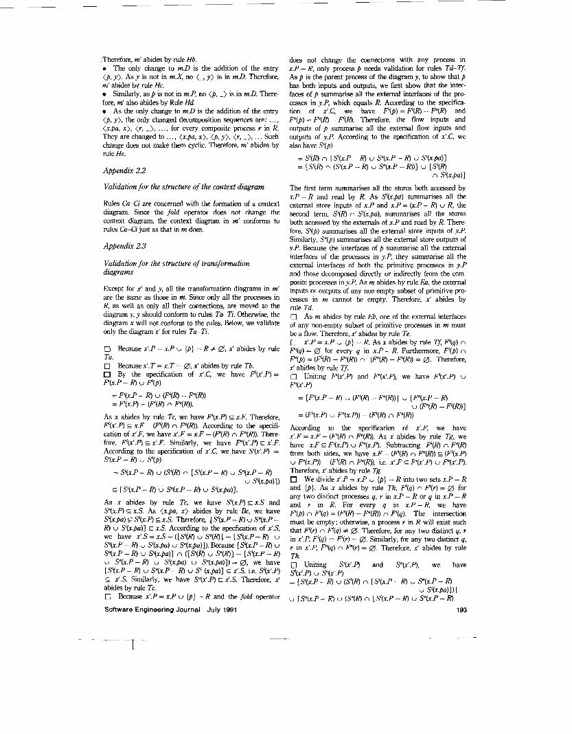
Therefore, m’ abides by rule Hb. 0 The only change to mD is the addition of the entry (p. y). As y is not in m.X, no (-, y ) is in m.D. Therefore, m’ abides by rule Hc. 0 Similarly, a s p is not in mP, no (p, -) is in m.D. There- fore, m‘ also abides by Rule Hd. 0 As the only change to m.D is the addition of the entry (p, y), the only changed decomposition sequences are: . . . , (x.pu, x), <r, -), ..., for every composite process r in R. They are changed to .. ., <x.pu, x ) , (p, y) , (r, -), . .. Such change does not make them cyclic. Therefore, m‘ abides by rule He.
Appendix 2.2
Validation for the structure of the context diagram
Rules CaCi are concerned with the formation of a context diagram. Since the fold operator does not change the context diagram, the context diagram in m’ conforms to rules CiCi just as that in m does.
Appendix 2.3
Validation for the structure of transformation diagrams
Except for x’ and y, all the transformation diagrams in m‘ are the same as those in m. Since only all the processes in R, as well as only all their connections, are moved to the diagram y, y should conform to rules Tu-Ti. Otherwise, the diagram x will not conform to the rules. Below, we validate only the diagram x’ for rules Tu-Ti.
0 Because x’.P = x.P U {p} - R # 0, x’ abides by rule Tu. 0 Because x’.T = x.T = 0, x’ abides by rule Tb.
By the specification of Y.C, we have F’(x‘.P) = F’(x.P - R) U P(p)
= F‘(x.P - R) U (F’(R) - P(R)) = F’(x.P) - (F’(R) n P(R)).
As x abides by rule Tc, we have F’(x.P) G x.F. Therefore, F(x’.P) c x.F - (F’(R) n P(R)). According to the specifi- cation of x‘F, we have x’.F = x.F - (F’(R) n P(R)). There- fore, Fi(x’.P) E x’.F. Similarly, we have P(x‘.P) E x’.F. According to the specification of x‘.C, we have s’(x’.P) =
= S’(x.P - R) U (s’(R) n [ s’(x.P - R) U s”(x.P - R)
s’(x.P - R) U s’(p)
U S’(x.pu)]) 5 [S’(x.P - R) U s”(x.P - R) U S’(X.~U)] .
As x abides by rule Tc, we have s’(x.P) EX.S and s”(x.P) G x.S. As (xpa, x ) abides by rule &, we have S’(x.pu) E s’(x.P) E x.S. Therefore, [ s’(x.P - R) U s”(x.P - R) U s’(x.pu)J E x.S. According to the specfication of +’.S. we have x’.S = x.S - ([S’(R) U S”(R)] - [s’(x.P - R) U
S”(x.P - R) U S’(X.PU) U s”(%.pu)l). Because [S’(x.P - R) U
S”(x.P - R ) U S‘(z.~u) J n ([S’(R) U s”(R)] - [ s’(x.P - R ) U s”(x.P - R) U s’(x.pu) U s”(x.pu)]) = a, we have [s’(r.P - R ) U So(x.P - R) U S’ (x.pu)] G x’.S, i.e. s’(x’.P) C_ %‘.S. Similarly, we have s”(x’.P) E x’.S. Therefore, x‘ abides by rule Tc. 0 Because x’.P = x.P U {p} - R and the fold operator
Software Engineering Journal July 1991
does not change the conndons with any process in x.P - R, only process p needs validation for rules Td-Tf. As p is the parent process of the diagram y, to show that p has both inputs and outputs, we first show that the inter- faces of p summarise all the external interfaces of the pro- cesses in y.P, which equals R. According to the specifica- tion of x‘.C, we have F’(p) = F ( R ) - P ( R ) and .F“(p) = P(R) - F’(R). Therefore, the flow inputs and outputs of p summarise all the external flow inputs and outputs of y.P. According to the specification of x’.C, we also have S’(p)
= s’(R) n [s’(x.P - R) U s”(x.P - R) U S’(x.pu)] = [s’(R) n (s’(x.P - R) U s”(x.P - R))] U [S’(R)
n S’(x.pu)]
The first term summarises all the stores both accessed by x.P-R and read by R. As S’(x.pu) summarises all the external store inputs of x.P and x.P = (z.P - R) U R, the second term, S’(R) n S’(x.pu), summarises all the stores both accessed by the externals of x.P and read by R. There- fore, S’(p) summarises all the external store inputs of y.P. Similarly, So@) summarises all the external store outputs of y.P. Because the interfaces of p summarise all the external interfaces of the processes in y.P, they summarise all the external interfaces of both the primitive processes in y.P and those decomposed directly or indirectly from the com- posite processes in y.P. As m abides by rule Ea, the external inputs or outputs of any non-empty subset of primitive prc- cesses in m cannot be empty. Therefore, x’ abides by rule Td. 0 As m abides by rule Eb, one of the external interfaces of any non-empty subset of primitive processes in m must be a flow. Therefore, x’ abides by rule Te. 0 x’.P = 1.P U {D} - R. As x abides by rule Tf, F’(q) n P(q) = 0 for every q in x.P - R. Furthermore, F’(p) n P(p) = (F’(R) - F“(R)) n (F“(R) - F(R)) = 0. Therefore, x’ abides by rule Tf. 0 Uniting F’(x’.P) and P(x’.P), we have Fi(x’.P) U
P ( x ’ . P)
= [F’(x.P - R) U (F’(R) - P ( R ) ) ] U [F”(x.P - R) U (F”(R) - F’(R))I
= (F’(x.P) U F”(x.P)) - (F‘(R) n F“(R))
According to the specification of Y.F, we have x’.F = x.F - (F’(R) n P(R)). As x abides by rule Tg, we have x.F E F’(x.P) U P(x.P) . Subtracting F’(R) n P(R) from both sides, we have x.F - (F’(R) n P ( R ) ) E (F‘(x.P) U P(x.P)) - (F‘(R) n P(R)), i.e. x’.F E F’(x’.P) U P(x’.P). Therefore, x’ abides by rule Tg.
We divide x’.P = x.P U {p] - R into two sets x.P - R and {p}. As x abides by rule Th, F’(q) n F’(Y) = 0 for any two distinct processes q, r in x.P - R or q in x.P - R and r in R. For every q in x . P - R, we have F’(p) n F’(q) = (F’(R) - P(R)) n F’(q). The intersection must be empty; otherwise, a process Y in R will exist such that F’(r) n F’(q) # $3. Therefore, for any two distinct q, r in x’.P, F’(y) n F‘(r) = 0. Similarly, for any two distinct q, r in x’.P, F(q) n P(Y) = D. Therefore, x’ abides by rule Th. 0 Uniting S‘(x‘.P) and P(x’.P), we have s’(x‘.P) U P(x‘.P) = [ S’(x.P - R) U (s’(R) n [S’(x.P - R) U S”(x.P - R)
U Is”(x.P - R) U (s”(R) n [s’(x.P - R) U s”(x.P - R) U s’(x.Pu)l)l
193

U S”(x.pa)l)l
U [So(@ n S”(x.pu)].
According to the specification of x‘S, we have x‘.S =
S’(x.pu) U S”(x.pa)]). As x abides by rule Ti, we have x.S c S’(x.P) U S”(x.P). Therefore, we have x’.S
E [ s’(x.P) U s”(x.P)] - ([ S’(R) U S”(R)]
= [ s’(x.P - R) U S”(x.P - R ) ] U [ s’(R) n S’(x.pu)]
x.S - ([ s’(R) U s”(R)] - [S’(*.P - R ) U S”(x.P - R) U
- [S’(x.P - R) U S”(x.P - R) U P(x.pa) U s”(x.pa)])
= ([S‘(x.P - R) U S”(x.P - R) U S‘(R) U s”(R)] - [s’(R) U S”(R)I)
U ([s’(R) U s”(R)] n [S’(x.P - R) U s”(x.P - 4 1 ) U ([s’(R) U s”(R)I n [S’(x.pa) U Y(x .pa)] )
= [s’(x.P - R ) U s”(x.P - R ) ] U [Si(@ n S’(x.pu)] U [ s”(R) n S”(x.pu)]
U [S’(R) n S”(x.pa)] U [S”(R) n S’(x.pa)J.
As (x.pu, x ) abides by rule Bd, we have s’(x.P) n S”(x.pa) s S’(x.pa). Intersecting b t h sides by s’(R), we have S ( R ) n s’(x.P) n P(x.pa) E S’(R) n S’(x.pa). Because s’(R) G s’(x.P), we have s’(R) n s”(r.pa) E S’(R) n S’(x.pa). Similarly, we have s”(R) U S’(x.pa) c S”(R) n So(x.pa). Subsequently, x’.S E [ s’(x.P - R) U s”(x.P - R ) ] U [s’(R) n S‘(x.pa)] U [S”(R) n S”(x.pu)], i.e. x’.S E S’(x’.P) U s”(x’.P). Therefore, x’ abides by rule Ti.
Aopendix 2.4
Validation for balancing
Balancing rules require that every parent-child pair of com- posite process and transformation diagram are balanced with each other by common connected flows and stores. The fold operator moves the set of processes R and all their connections from the diagram x into the newly created diagram y, but leaves alone the connections of any process in x.P - R. Therefore, we only need to validate the bal- ancing of the two pairs (p, y) and (x‘.pa, x’) . We first validate the balancing of (p, y) as follows.
0 According to the specfication of y.C, we have F’01.P) =
U, E F’(7) = F’(R) and F(y.P) = U, E F(Y) = F“(R). According to the specification of x’.C, we have F(p) = F’(R) - P(R) and P ( p ) = P(R) - F’(R). Therefore, P(p) = F’(y.P) - P(y.P) and F(p) = P(y.P) - F’Cy.P), i.e. ( p , y) abides by the flow balancing rule, rule Ba. 0 According to the specification of y.S and x.C, the set of local stores in y is
Y.S - (S‘O) U S q P ) ) = [S‘(R) U S”(R)] - [(S’(R) n [s’(x.P - R )
U (s”(R) n [s’(x.P - R) U s”(x.P - R) u”&.Pa)l)l
U S”(x.P - R) U s’(x.pu)])
= [s’(R) U S”(R)] - [(s’(R) U s’(R)) n (s’(x.P - R) U s”(x.P - R))]
- [(S’(R) U s”(R)) n (S’(x.)a) U s”(x.pa))l
- (S’(x.pa) U S”(x.pa)) E x.S - ( s ’ ( x q U ) U SO(x.pa))
= [s’(R) U S”(R)] - [(s’(R) U S”(R)) n (S’(x.P - R) U s”(x.P - R))]
i.e. every local store in y is a local store in x. Because the term (s’(R) U S”(R)) n (s’(3c.P - R) U s”(x.P - R)) has been subtracted, local stores in y are local stores in x without connection with any process in x.P-R. As x abides by rule Bb, every local store in x will have a reader and a writer, not the same one, in x. Therefore, both reader and writer of every local store in y must be in R, i.e. y.P, namely, (p, y) abides by rule Bb. 0 According to the specification of x’.C, we have s’(p) = s’(R) n [ s’(x.P - R) U P(x.P - R) U S’(x.pa)] E s’(R). According to the specification of y.C, we have s’(y.P) = U,,Rs’(r) = s’(R). Therefore, s’(p) c s’fy.P). Similarly, we have S”(p) 5 S”(y.P). Therefore (p, y) abides by rule Bc. 0 According to the specification of y.C, we have 9Cy.P) =
U, E Y(r) = s”(R). Intersecting s’@) and s”Cy.P), we have
s’@) n s”f.y.P) = (s’(R) n [s’(x.P - R) U s”(x.P - R) U S’(x.pu)])
G s”(R) n [ s’(x.P - R) U s”(x.P - R) U S’(x.fiu)] = s”(R) n [s’(x.P - R ) U s”(x.P - R) U (S’(x.pa)
E S“(R) n [ s’(x.P ~ R ) U s”(x.P - R) U (S‘(x.@a)
n S”(R)
n S”(R))I
n S”(x.P))].
As (x.pa, x ) abides by rule Bd, we have S’(x.pa) n S”(x.P) E s”(x.pa). Thus, S(p) n S”(y.P) E s”(R) n [s’(x.P - R) U S”(x.P - R) U S”(x.pa)] = Y(qX specified in x.C. Similarly, we have So@) n s’(y.P) E S(p). There- fore, ( p , y) abides by rule Bd.
Thus, we have validated the balancing of the pair (p, y). Now, we validate the balancing of <x’.pa, x ’ ) in the follow- ing.
According to the specification of x’C, we have
(F’(R) - P ( R ) ) = F‘(x.P) ~ (F’(R) n F”(R)). Similarly, we have F“(x’.P) = F“(x.P) - (F’(H) n P(R)). Subtracting the two equations from each other, we obtain F’(x’.P) - F“(x’.P) = F’(x.P) - F“(x.P) and P(x’.P) - F’(x’.P) = P(x.P) - F’(x.P). As (x.pu, x ) abides by rule Bu, we have F’(x.pa) = F‘(x.P) - P ( x . P ) and P(x.pa) = F ( x . P ) - F’(x.P). Thus, F’(x‘.P) - P(x’.P) = F’(x.pu) and Fo(x’.P) - F‘(x’.P) = P(x.pa). Because the fold operator does not change any connection with x.pa, we have F‘(x’.pa) = F’(x.pu) and P(x’.pu) = F“(x.pa). Therefore, F’(x’.P) -Fo(x‘.P) = F’(x’.pu) and F(x’.P) - F’(x’.P) = F“(x’.pa), i.e. (x’.pu, x ’ ) abides by the flow balancing rule Ba.
Rule Bb requires that every local store of a transform- ation diagram is accessed by at least two processes in the diagram, one as a reader and the other as a writer. Consider a local store, say s, of the diagram x, which has been changed to x‘ and y. There are three cases. The first is that the two processes accessing s are both in x.P - R. This is no problem because every process in x.P ~ R is in x’.P. The second case is that one process is in x.P - R and the other process is in R. To abide by rule Bb, the store s must be moved all the processes in R toy. and p , residing in x’, is the parent process of y). This requirement is true because S‘(R) n [S’(x.P - R) U s”(x.P - R ) ] E s’(R) n [s’(x.P - R) U S“(x.P - R) U S’(x.pa)] = S’(p) and s”(R) n [s‘(x.P -
F‘(x‘.P) = (F’(x.P) - F’(R)) U F’(p) = (F’(x.P) - F’(R)) U
194
, 7 -r r--
Software Engineering Journal July 1991

R) U s”(x.P - R)] c s”(R) n [S’(x.P - R) U s”(x.P - R) U
S”(x.pu)] = s”(p). The third case is that all the processes accessing s are in R. If the store s is not connected with the parent process of x , the store must be a local store of the diagram y , i.e. it must not be connected with p , the parent process of y. This requirement is true because [S’(R) U
S”(x.pa)] = y.S -‘(S’(p) U s”(p)), the right side of which is the set of local stores in y. (The reason why the left side is equal to the right side has been shown above.) By the three cases, we conclude that (x‘.pu, x ’ ) abides by rule Bb. 0
s”(R)] - [S’(x.P-R) U s” (x .P-R) ] - [S’(x.pu) U
According to the sk f i ca t ion of x‘.C, we have S’(x’.P)
(F’(x.pu) U P(x.pu)) = 0, uniting the two sets of local flows, we obtain the set x.F - (F’(x.pu) U F“(x.pa)), which is the set of local flows in x. As m abides by rule Ub and x E m.X, local flows in x are different to any flows in the context diagram. Subsequently, local flows in x’ and in y are different to any flows in the context diagram. Therefore, m’ abides by rule Ub. 0 We are aware that the union of the two sets of local flows in x’ and in y equals the set of local flows in x. Since m abides by rule Uc and x E m.X, local flows in x are differ- ent to local flows in any transformation diagram in m, other than x. In addition, m’.X = m.X U {x’, y } - { x } . Therefore,
As (x.pu, x ) abides by rule Bc, we have S’(x.pu) E s’(x.P). Then, S’(x.P) n S’(x.pa) = S’(x.pa), the right side of which equals S’(x’.pu) as the fold operator does not change any
flows. Therefore, m’ abides by rule Uc. 0
stores inn’ is According to the specification of x’.S, the set of local
connection with %.pa. Therefore, S’(x’.pa) c S’(x’.P). Simi- larly, we have s”(x’.pu) c s”(x’.P). Therefore, (x’.pa, x ’ ) abides by rule Bc. 0 According to the specification of x‘.C, we have S’(x’.pu) n s”(x’.P)
x,.S - (S’(x,9a) s”(x,,pu)) = x.S - ([S’(R) U s”(R)] - [S’(x.P - R)
= (x.S - [.!?(RI U s”(R)I) U ([S’(R) U s”(R11
U SO(x.P - R) U S’(x.pa) U So(x.pu)]) - (S’(x.Pu) U P(x.pa))
= S’(x.pu) n [s”(x.P - R) U (s”(R) n [S’(x.P - R)
= S’(x.pu) n (s”(x.P) n [S’(x.P - R) U s”(x P - R)
G S’(x.pa) n s”(x.P).
n [ S’(x.P - R) U s”(x.P - R)] )
U S”(x.pu)]) - (S’(x.fiu) U s”(x.Pu))
n [ S’(x.P - R) U s”(x.P - R)] )
U s”(x.P - R) U s”(x.pa)])l
U S’(X.PU)l)
U ([ S(R) U s”(R)] n [ S’(x.pu)
= (x.S - [S’(R) U S”(R)]) U ([S’(R) U s”(R)]
As (x.pu, x ) abides by rule Bd, we have S’(x.pu) n s”(x.P) E S”(x.pu), the right side of which equals S”(x’.pu). Therefore, S’(x’.pu) n So(x’.P) E S”(x’.pu). Simi- larly, we have S”(x’.pu) n S’(x‘.P) E S’(x‘.pa). Therefore, (x’.pu, x ’ ) abides by rule Bd.
Appendix 2.5
Validation for the originality of elements
Since the fold operator has partitioned the diagram x into x’ and y, in order to demonstrate that m‘ conforms to the orig- inality conventions of elements, we must consider cross- references between x’ and y, between x‘ and z’s, and between y and z’s, when z is a diagram in m’ other than x’ and y.
0 According to the specfication of x’.P and y.P, we have
- (S’(x.pu) U S4(x.pu)) E x.S - (S’(x.pu) U S”(x.pa))
i.e. every local store in x’ is a local store in x. We are aware that every local store in y is a local store in x. As m abides by rule Ud and x E m.X, local stores in x are different to local stores in any transformation diagram in m, other than x. In addition, m‘.X = m.X U {x ’ , y } - { x } . Therefore, local stores in x‘ and in y are different to any local stores in any transformation diagram in m‘, other than x’ and y. Further- more, intersecting the two sets of local stores in x’ and in y , we have [x’S - (S’(x’.pu) U s”(x’.pu))] n b.S - (S’(p) U
s”(p))] = [(x.S- [s’(R) U s”(R)]) U ([S’(R) U s”(R)] n [S’(x.P - R) U s”(x.P - R ) ] ) - (S’(x.pu) U s”(x.pu))] n [[S’(R) U s”(R)] - [(S’(R) U s”(R)) n (S’(x.P - R) U
s”(x.P ~ RI)] ~ (S’(x.pu) U So(x.pa))] = a, i.e. x‘ and y have no common local stores. Therefore, m’ abides by rule Ud.
x‘.P = x.P U { p } - R and y.P = R. Intersecting both, we have Uniting both, we have x‘.p y , p = (x ,p ~ R) R = x.p Validation f o r the external interfaces of process groufls
x ’ . ~ n y . ~ = ( x . ~ u { p } - R) n R = D. Appendix 2.6
U {p} . Note that p 4 &.P, and so‘-p 4 z.P for every z E mX U {m.cd}. As x abides by rule Uu, we have (x.P n z.P) = 0 for every z E mX U {m.cd} - { x } , i.e. m’X U {m’.cd} - {x’ , y } . Therefore, x’.P n z.P = 0 and y.P n z.P = 0 for every z E m’.X U {m’.cd} - {x’, y}. As a result, m’ abides by rule Uu. 0 According to the specification of x‘F, the set of local flows in x’ is x‘.F - (F’(x’.pu) U P(x’.pa)) = x.F - (F’(R) n P(R)) - (F’(x.pu) U F“(x.pu)). According to the specifi- cation of y.F and x’.C, the set of local flows in y is
(P(R) - F‘(R))) = F’(R) n F(R). Because (F‘(R) n P(R)) n y.F - (F‘@) U P@)) = (F’(R) U P(R)) - ((F‘(R) - P(R)) U
Rules Ea and Eb are concerned with the external interfaces of any subset of primitive processes in a system model. Since the fold operator neither deletes, creates any primitive processes, nor changes any connections with primitive pro- cesses in m, m’ conforms to rules Ea and Eb, as does m.
The paper was first received on 13th August 1990 and in revised form on 4th February 1991.
The authors are with the Institute of Computer Science and Infor- mation Engineering, National Chiao Tung University, Hsinchu, Taiwan 3oO50, Republic of China.
Software Engineering Journal July 1991 195