restaurant enterprise solution version 4.8 installation … · restaurant enterprise solution...
TRANSCRIPT

Restaurant Enterprise Solution Version 4.8Installation Guide
General Information
About This Document
This document provides installation and setup instructions for the MICROS Restaurant Enterprise Solution (RES) Version 4.8 software. The process ensures the proper transfer and configuration of the files, programs, and databases required for the smooth operation of the applications.
The procedures described in this document are applicable to both new and upgraded systems.
*****************************IMPORTANT*******************************
In RES 4.8 there is a dependency on the file WinHTTP.dll. This file is not included in the Windows NT operating system. Consequently, RES 4.8 will not run on Windows NT. Windows NT clients are not supported.
***************************************************************************
MD0003-121Revision E
April 13, 2010Page 1 of 184
General InformationDeclarations
Declarations WarrantiesAlthough the best efforts are made to ensure that the information in this document is complete and correct, MICROS Systems, Inc. makes no warranty of any kind with regard to this material, including but not limited to the implied warranties of marketability and fitness for a particular purpose.
Information in this document is subject to change without notice.
No part of this document may be reproduced or transmitted in any form or by any means, electronic or mechanical, including photocopying, recording, or information recording and retrieval systems, for any purpose other than for personal use, without the express written permission of MICROS Systems, Inc.
MICROS Systems, Inc. shall not be liable for errors contained herein or for incidental or consequential damages in connection with the furnishing, performance, or use of this document.
Trademarks FrameMaker is a registered trademark of Adobe Corporation.Microsoft, Microsoft Excel, Win32, Windows, Windows®95, Windows 2000 (Win2K), and Windows NT are either registered trademarks or trademarks of Microsoft Corporation in the U.S. and/or other countries.Visio is a registered trademark of Visio Corporation.All other trademarks are the property of their respective owners.
MD0003-121Revision EApril 13, 2010Page 2 of 184

General InformationContents
Contents To help you navigate the document, information is organized in sections and displayed in the following sequence:
Who Should be Reading This Document................................ 4
What the Reader Should Already Know................................. 4
Before You Begin: Tips, Traps, and Precautions .................... 5
Site Requirements ................................................................... 14
Before Running Server Setup.................................................. 23
Running Server Setup.............................................................. 28
Running Client Setup .............................................................. 49
Installing Point Releases and Hotfixes.................................... 54
Appendix A: SEI KDS Client Hardware Setup ...................... 62
Appendix B: Silent Installation Procedures (Server) .............. 68
Appendix C: GSS Setup.......................................................... 73
Appendix D: System Security Setup....................................... 77
Appendix E: Frequently Asked Questions (FAQs) ................. 83
Appendix F: Wireless Workstation 4 ..................................... 102
Appendix G: SwitchTo.exe .................................................... 107
Appendix H: Order Confirmation Board (OCB)..................... 110
Appendix I: Table Management System (TMS) ..................... 132
Appendix J: Customized Installation Procedures.................... 142
Appendix K: Pre and Post Custom Installation Procedures.... 143
Appendix L: Removing RES 3.x Software ............................. 144
Appendix M: RES Security .................................................... 149
MD0003-121Revision E
April 13, 2010Page 3 of 184
General InformationWho Should be Reading this Document
Who Should be Reading this Document
This document is intended for the following audiences:
MICROS Installers/Programmers
MICROS Dealers
MICROS Customer Service
MICROS Training Personnel
MIS Personnel
What the Reader Should Already Know
This document assumes that you have the following knowledge or expertise:
Operational understanding of PCs
Understanding of POS terminology and concepts
Working knowledge of the Microsoft Windows interface
MD0003-121Revision EApril 13, 2010Page 4 of 184

RES Setup ProceduresBefore You Begin: Tips, Traps, and Precautions
RES Setup Procedures
Before You Begin: Tips, Traps, and Precautions
Before running the RES Setup procedure, the following should be noted:
The individual installing the software must be logged on as “Administrator” before running RES Setup on a Microsoft® Windows XP or Windows 2003 system.
Make sure that all programs/applications are closed on the PC. If the system detects an active program/process during the installation routine, a notification to close may display.
When upgrading on a RES system where the MICROS Portal is installed, be sure to manually shut down the Micros Agent and Micros Watchdog services. Failure to shut down these Portal-related services can result in a system lockup during database conversion.
MICROS recommends using NTFS partitions for both the Operating System and the MICROS drive. This is because the NTFS file system provides greater security than FAT partitions.
Before attempting a RES 4.x installation, all versions of RES v. 3.x must be completely removed from the system. RES v. 3.x must also be removed before upgrading the Operating system to either XP or 2003.
Note: Ensure that you have an upgradeable version of RES v. 4.x before attempting to apply this RES 4.x patch.
RES 3.x cannot be removed successfully from an XP or 2003 system. Be advised that manually removing the MICROS tree and registry will not equate to a clean removal of RES.
Refer to page 40 for instructions on removing the RES software.
Before installing Win 2003 or XP on the server, make sure that any OPOS devices and related software that need to be installed are compliant with the operating systems. Failure to do so may prevent KDS Controller from loading after setup.
MD0003-121Revision E
April 13, 2010Page 5 of 184
RES Setup ProceduresBefore You Begin: Tips, Traps, and Precautions
When installing on a Win 2003 system, double-clicking on Setup.exe to run a full RES build will display the following warning:
“This type of file could harm your computer if it contains malicious code.”
Users then have the option of pressing Open (to continue with setup), Cancel (to exit), or a generic More Info button. This can be problematic, particularly with remote installations.
To avoid this, users can disable the warning message as follows:
1. Open Internet Explorer.
2. Go to Tools | Internet Options | Security | Internet | custom level.
3. Scroll down to Launching Applications and unsafe files and change the value from Prompt to Enable.
During RES 4.x installation, both the Backup Server Service (ResBSM.exe) and the KDS Controller are installed to all clients running the XP or 2003 operating systems. Though installed, please note that the Backup Server Service and KDS Controller are not supported on Microsoft XPE and WePOS.
MICROS recommends assigning no more than 8 print devices to a client. More than that may cause the print service to fail.
WS4's will need at least 128 MB of RAM installed. Users can verify the amount of RAM by checking My Computer | Control Panel | System | Memory. If the amount of Program Memory Allocated is approximately 50000 KB, then the PC has 128 MB of RAM. If the value is only 17000 KB, then it only has 64 MB of RAM and may experience low memory errors.
Rerunning RES Version 4.0 or higher for purposes of installing, modifying, or repairing any of the applications will reset all of the applications to their General Release versions. If you have already installed service packs to RES 4.x, you will need to rerun all service packs again. Failure to do may prevent you from opening previously installed programs.
MD0003-121Revision EApril 13, 2010Page 6 of 184
RES Setup ProceduresBefore You Begin: Tips, Traps, and Precautions
Powering off either the WS4 or the Server during an upgrade to a version of RES can cause the WS4’s compact flash to become corrupt. This can also occur if you pull the power cord out of the WS4 while it is writing to the compact flash. To correct the problem, the compact flash must be reformatted using a compact flash reader.
When using an Eclipse PCWS in a RES 4.x system, be sure to set the O/S field to what the actual operating system is. If installing a new Operating System, set the O/S field to the new Operating System prior to installing the new OS. Failure to do so can cause some COM Port issues.
To view and/or modify the setting:
1. Reboot the workstation.
2. Press F2 to enter the BIOS setup program.
3. Go to the Advanced tab.
4. Verify that the O/S field is set to the workstation’s Operating System.
Since Windows XP is not available as a selection, the WinNT2K selection should be made for XP installations.
When updating the system’s Time Zone setting, users must stop/start RES services before attempting to run POS Operations. This will resynchronize the RES application time zones (which are set on startup) with those on the updated POS clients.
Failure to do so, or to reboot the system, will cause errors when using the Future Order feature and may affect other timer-related functionality.
When running Setup with Microsoft Anti-Spyware installed, the system displays a series of warning messages when the MICROS Secure Desktop or other RES applications are started. Should this occur, users are advised to simply press the Allow button to continue. Do not press the Block key, as this will cause problems with the system.
MD0003-121Revision E
April 13, 2010Page 7 of 184

RES Setup ProceduresBefore You Begin: Tips, Traps, and Precautions
When upgrading the HHT 8800 from RES 3.x to RES 4.0 or higher, be advised that the HHT Loader will not check for Software Updates until the device is either rebooted or re-cradled after use.
The firewall on a RES 4.0 server must have the following ports open before it can accept requests from a Win 32 client:
TCP: 7300UDP: 7301
Firewalls should be enabled prior to installing RES 4.x on a Win 2003 Server. If the firewall is enabled after installation, the clients will not be able to communicate with the server and will continuously display prompts for Backup Server Mode (BSM) and Stand-alone Resiliency (SAR).
To fix the problem post installation, users should:
1. Start the firewall from Control Panel | Windows Firewall.
2. Run Micros\common\Bin\ConfigureICF.bat. This will update the exceptions list that RES needs to successfully run with the firewall enabled.
For more on firewall setup, see Appendix D, page 81.
Certain Micros applications (e.g., KDS Controller, Backup Server, ILDS, IFS) can be configured to run on both the server or a client (XP or 2003). When switching the configuration to run a service on a PC, users should do the following to ensure that the system updates properly:
1. Make the necessary changes in POS Configurator to run the service on the PC.
2. Open Micros Control Panel.
3. Highlight Restaurant and click Reload. This will propagate all changes out to all clients.
4. Reboot the Server.
MD0003-121Revision EApril 13, 2010Page 8 of 184

RES Setup ProceduresBefore You Begin: Tips, Traps, and Precautions
5. Reopen MICROS Control Panel. Highlight Restaurant and click Reboot All to reboot all of the clients.
This version of the software supports PCWS Model Ultra running Windows NT or higher as a client only. A minimum of 128 MB of RAM is required.
If a PCWS is to be used as the RES server, MICROS recommends the PCWS Model 2010 with a Pentium processor and 512 MB of RAM.
When using the HP 100 USB printer, the correct procedure is to set the device as the Windows default printer, while leaving the Default Printer Name blank in POS Configurator (System | Restaurant | Description). Otherwise, selecting this printer as the 3700 default will result in type size and formatting errors.
RES Versions 4.x do not support Fast User Switching on the Windows XP platform. This option allows 2 users to log onto the computer simultaneously, and to switch between active users without having the current user log off first. If enabled, it may cause some applications and/or processes to fail.
The ILDS folder and files are created in \Micros\common\etc (RES 4.x instead of \Micros\res\pos\bin (RES 3.x).
If running a RES patch, the system will reference the wrong RES prerequisite version number in Add/Remove Programs. This is because RES patches are unable to update version information in Add/Remove Programs.
When a RES 4.0 Server is patched, all clients except for the Symbol 8800 will be updated automatically. The Symbol 8800 will need to be rebooted or re-cradled after the server has been patched in order to receive the update.
RES must be removed prior to upgrading the Operating System to either Microsoft XP or 2003. RES cannot be completely removed from an XP or 2003 system. Even manually removing the MICROS tree and registry will not result in a clean removal of RES.
MD0003-121Revision E
April 13, 2010Page 9 of 184
RES Setup ProceduresBefore You Begin: Tips, Traps, and Precautions
If upgrading from RES Version 3.x to RES 4.x, the 3.x version must be removed before attempting installation. Otherwise, setup will not proceed. For instructions on removing RES 3.x from the system see Appendix L: Removing RES 3.x Software beginning on page 144.
There are conversion issues due to custom tables, triggers, stored procedures, etc. that Sybase 9 cannot handle. Therefore, every customer must upgrade their existing database on a lab system prior to installing at a live site. This serves to verify that the upgrade will be successful.
RES version 3.x is installed to the C:\Micros folder by default. RES version 4.x, is installed to C:\Program Files\Micros by default. Because there is a space between the “Program” and “Files” in the folder name “Program Files,” any custom scripts and batch files should contain quotes (e.g., “,”) when referencing the MICROS folder architecture. For example:
%microsdrive%\Micros\Common\Bin\registerIIS.bat
In version 4.x (if Micros is installed to Program Files), this same line would need to be surrounded by quotes (e.g., “%microsdrive%\Micros\common\Bin\registerIIS.bat”).
The LX Display Controller needs to be configured to use the correct touch screen driver when installed. If this is not done, the touch screen will still work, but the tool bar buttons may become depressed and will not come back up.
Follow these steps to configure the correct touch screen driver:
1. Go to Start | Programs | Windows Explorer | Control Panel | Touch Display.
2. Select the correct driver for your monitor.Ex: Elo Touch
3. Select the correct connection type.Ex: USB
4. Reboot the Display Controller.
MD0003-121Revision EApril 13, 2010Page 10 of 184

RES Setup ProceduresBefore You Begin: Tips, Traps, and Precautions
To avoid a possible disruption in network communications, set the following option on the server and any clients that are allowed to go into Standby mode.
1. Open Device Manager and right-click on your Network Card.
2. Select Properties | Power Management and then Disable the Allow the computer to turn off this device to save power option.
The Setname Utility (setname.cfg) is no longer supported on clients running RES versions 4.3 or higher. Setname of the servers is still supported. This will have no impact on functionality because when RES is installed on a Win32 client, CAL automatically changes the client’s name and IP Address to match what is configured in the database.
Database Conversion
MICROS no longer supports database Version 3.0 or below. The conversion process will only work with database Version 3.1 or higher.
An existing Version 3.1/3.2 database with multiple languages created through the Translate.exe application may not convert properly. The first language in the database, which is the English US language, will convert correctly.
When upgrading an existing database, Sybase 9 may have trouble converting custom elements such as tables, triggers, and stored procedures that are not supported in this version. To avoid this problem, customers should upgrade their existing database on a lab system prior to installing at a live site. This will ensure that the database is viable, or allow the customer to make needed corrections if it is not.
Licensing After accepting the Licensing Agreement at the start of the RES Version 4.x InstallShield program, if you press Next then Back to return to the Licensing screen, you will have to accept the agreement twice more before the installation will continue.
MD0003-121Revision E
April 13, 2010Page 11 of 184

RES Setup ProceduresBefore You Begin: Tips, Traps, and Precautions
This version of the software requires a MICROS 4.x activation code for each RES module, with the exception of the Guest Services Solution Module.
MD0003-121Revision EApril 13, 2010Page 12 of 184

RES Setup ProceduresBefore You Begin: Tips, Traps, and Precautions
Labor Management Access
When installing a site with RES 4.0 or higher, users will be unable to access Labor Management if the only features installed during setup are:
RES InfrastructureRES POS ApplicationsLabor Management
The problem can be corrected by following these steps:
1. Install the RES 4.0 or higher software.
2. Browse to the root of the RES 4.x Software CD and double-click on the AddPM.reg.
3. Turn on the system as normal.
This issue will be permanently corrected in the next RES release.
Guest Services Solutions (GSS)
If you are currently running GSS on a RES 3.0 system and are upgrading to version RES 4.x, please refer to the RES 3.2 Service Pack 3 ReadMe First, MD0003-065 for instruction on updating your GSS configuration prior to the RES 4.x installation.
Kitchen Display System (KDS)
The .NET framework version 1.1 must be loaded on Windows NT and 2000 clients that want to run the KDS display application.
Documentation Documentation is available from the MICROS website, on the RES Product page.
MD0003-121Revision E
April 13, 2010Page 13 of 184

RES Setup ProceduresSite Requirements
Site Requirements In order to successfully install and enable a RES Setup system, the following requirements must be met:
1 Windows NT is not supported.
2 Manager Procedures will only work with .NET version 1.1 installed. Sites that have upgraded to .NET version 2.0 can re-register the Micros install to version 1.1 by running the RegisterIIS.bat file, located in the \MICROS \Common\bin folder on the Server.
3 Must be loaded on Win 2000 and NT clients that want to run the KDS display application.
4 Requires IIS 5.0 for WinXP Pro and 6.0 for Win 2003. IIS is NOT required on clients.
Servers Clients
Win2003 XP Win
2003Win
20001XP Pro NT1
Win XP Pro sp2 X X
Win 2003 X X
Win 2000 Pro sp3 X
NT 4.1 sp 6a or greater
IE 6.0 sp1 or higher X X X X X
.NET Framework 1.1 sp12
X X X X3 X
IIS4 X X
MSI 3.0 X X
MDAC 2.6 sp 1
ASP.Net X X
MD0003-121Revision EApril 13, 2010Page 14 of 184

RES Setup ProceduresSite Requirements
Additional Software RequirementsThe following third-party applications are used with RES Setup. These application versions must not be changed by the installation of other third-party software. Any changes to the software application will make the RES System unsupportable.
Application Version
Microsoft DCOM 1.3 or higher
ODBC 3.52 or higher
Sybase Adaptive Server 9.0.2.3267
Crystal Reports Professional* 9.2.3.1336
Borland Delphi Engine 5.1.1.1
Sentinel Software Key Driver 7.0
Adobe Acrobat Reader 6.0 or higher
ADO 2.6 sp1 or higher
*Crystal Reports viewer is installed with RES. If report development is required, the installer must load a full version of Crystal Report Professional. If done, RES Setup must be reloaded afterwards.Reports developed in later versions of Crystal must be saved using Version 9 format.
MD0003-121Revision E
April 13, 2010Page 15 of 184

RES Setup ProceduresSite Requirements
Hard-Drive Space RequirementsThe space requirements listed below assume that the full range of options are to be installed:
Prior to setup, the system calculates how much space is required for installation of the selected features. If the available disk space is inadequate, an error message is displayed.
RES Environment 2003/XP Server
Windows Client
Clean, no prior RES installation
1.2 GB + size of DB
600 MB
Over existing RES 1.3 GB + size of DB
600 MB
Note RES 4.0 and higher requires a minimum of 200 MB free space on the root drive, (usually C:). This is true even if choosing to install RES to a different drive.
For optimum system performance, 30% of the root drive should be free space.
MD0003-121Revision EApril 13, 2010Page 16 of 184

RES Setup ProceduresServer Requirements
Server Requirements
OverviewThis section provides guidelines for configuring a RES store system. Please refer to the Enterprise Management site survey and consult with MICROS Research & Development, Product Management when configuring the EM corporate server.
There are four computer resources that affect system performance:
Memory (RAM)Hard-Disk SizeController Type/NumberProcessor Speed
The demands placed on these resources by RES and Enterprise Office applications are a function of the database and the number of transactions posted in the system. Transactions may be posted from any one of the RES applications. These guidelines are predicated on the RES server being dedicated to RES applications only. If the RES server is to be used for other third-party applications, additional resources may be required. Please refer to third-party software source requirements when determining the configuration needs of your system.
The recommendations provided in this section are designed to yield an acceptable performance under average conditions and based on the current version of software. Every effort is made by the development group to prevent significant increases in server resource requirements as RES moves forward. However, because of our reliance on third-party components such as the Microsoft Operating System, Sybase ASA DBMS, and other tools, we cannot guarantee that the suggested minimum requirements will be suitable for future versions of RES, Sybase, and the Windows OS.
For increased performance, or if the customer is planning future upgrades, MICROS recommends increasing the hardware to the next level of server configuration. These recommendations are based on the current Personal Computer offerings.
MD0003-121Revision E
April 13, 2010Page 17 of 184
RES Setup ProceduresServer Requirements
DisclaimerThe MICROS Research & Development team has neither tested nor certified PCs from other manufacturers, nor does it keep current on their offerings.
As a rule, the MICROS Customer Service and Research & Development groups do not support PCs from other manufacturers. Non-MICROS PCs should be evaluated in terms of their equivalence to the Hewlett-Packard model. For example, a Dell Optiplex is an equivalent model for an HP Vectra, but NOT for an E60 or E800 Net Server.
MICROS neither recommends nor supports loading an operating system on a hardware platform that is not officially supported by the manufacturer. For example, the E60 and E800 do not support Windows XP Pro, while the Vectra line does not support Windows 2003.
Service and support for customers not using a MICROS-approved product will be the total responsibility of the end user. (Note: Performance testing and initial configuration of a third-party PC is available at prevailing rates.)
Further System RecommendationsPerformance can be enhanced significantly by increasing RAM and by storing the database on a second hard drive, or moving to a RAID configuration with a caching RAID Controller.
Clients — Windows XP Pro Hard Drive clients provide better performance for larger configurations.
Network — A 10-MB flat network provides adequate performance for a 25-workstation configuration. Integrating into existing, non-MICROS networks requires special considerations.
When determining system size, the total number of clients refers to all units, including POS Clients, KDS Clients, Hand-Held Terminals, and Backoffice Clients.
MD0003-121Revision EApril 13, 2010Page 18 of 184
RES Setup ProceduresServer Requirements
Resiliency – Raid 5 is a resilient hard-drive configuration that will protect a site in the event of a single hard drive failure. Any sites that require additional operational and data resiliency should consider using a Raid 5 configuration on an appropriate server. It is always recommended to utilize raid configurations through the hardware controller and not recommended to use the raid features of the Operating System.
Dual Processors – RES 3.x does not support servers with Dual Processors. RES 4.0 and higher do support Dual Processors and Dual Core Servers, however RES applications will not take advantage of the dual-processor/core technology. This means that the user will not see a major performance improvement over a computer utilizing a single processor.
RES does not currently support servers with hyper-threading enabled; that configuration is not recommended at this time.
For system purchases, RAM should be purchased in 1 GB increments. Not only is this the most cost effective option, it is the most efficient. Larger RAM means less slot are used and space is preserved for future expansion.
A mass storage device is recommended when configuring your system. Make sure that this backup storage device has sufficient capacity to hold the MICROS database and all other critical files.
MICROS recommends backing up to the server’s physical hard-drive or to another PC on the network (i.e., an Eclipse workstation). Tape drives may still be used, but are no longer common. ZIP, Jazz, and CD Read/Write drives are not recommended as they do not have adequate capacity to backup a RES database.
RES 4.0 and higher installs an encrypted database. Sybase recommends that no compression be used when storing an encrypted database. This should be taken into consideration when selecting a backup storage device.
MD0003-121Revision E
April 13, 2010Page 19 of 184

RES Setup ProceduresServer Requirements
Hard drives can be an important factor in selecting a PC. For maximum system performance, at least 33% of the hard-drive should be free during operations. This is true for each hard drive and each drive partition.
Disk defragmentation tools such as Diskeeper are recommended to maintain hard drives at their most optimum performance. Note that when upgrading to RES 4.0 or higher, the size of the database will grow a minimum of 40%.
System Configuration TypesSystem configuration is based on three factors: 1) number of clients, 2) volume of transactions, and 3) POS Only versus full RES (POS and Enterprise Office) installation.
For clarity, transaction levels are defined as follows:
Low Transaction volume — Refers to a site where the volume of transactions rarely engages all workstations simultaneously. Hotels and some fine dining table-service restaurants (TSRs) are typically low-volume sites.
Medium Transaction volume — Refers to a site where all workstations are often (but not always) engaged simultaneously. Family-style TSRs and moderately busy quick-service restaurants (QSRs) are examples of medium-volume sites.
High Transaction volume — Refers to a site where all workstations are continually and simultaneously engaged. High transaction rates, during extended, peak meal periods are typical of QSRs. Also included in this category are TSRs and hotels with a busy bar, and stadiums and arenas where the transaction volume is concentrated during an event timeframe.
MD0003-121Revision EApril 13, 2010Page 20 of 184
RES Setup ProceduresServer Requirements
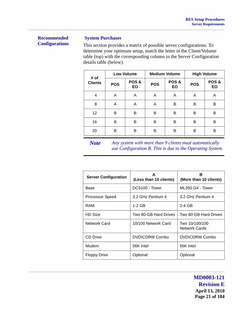
Recommended Configurations
System PurchasesThis section provides a matrix of possible server configurations. To determine your optimum setup, match the letter in the Client/Volume table (top) with the corresponding column in the Server Configuration details table (below).
# of Clients
Low Volume Medium Volume High Volume
POS POS & EO POS POS &
EO POS POS & EO
4 A A A A A A
8 A A A B B B
12 B B B B B B
16 B B B B B B
20 B B B B B B
Note Any system with more than 9 clients must automatically use Configuration B. This is due to the Operating System.
Server Configuration A(Less than 10 clients)
B(More than 10 clients)
Base DC5100 - Tower ML350 G4 - Tower
Processor Speed 3.2 GHz Pentium 4 3.2 GHz Pentium 4
RAM 1-2 GB 2-4 GB
HD Size Two 80-GB Hard Drives Two 80-GB Hard Drives
Network Card 10/100 Network Card Two 10/100/100 Network Cards
CD Drive DVD\CDRW Combo DVD\CDRW Combo
Modem 56K Intel 56K Intel
Floppy Drive Optional Optional
MD0003-121Revision E
April 13, 2010Page 21 of 184
RES Setup ProceduresClient Requirements
1POS Backup Server must be the same operating system as the RES Server.
Client Requirements
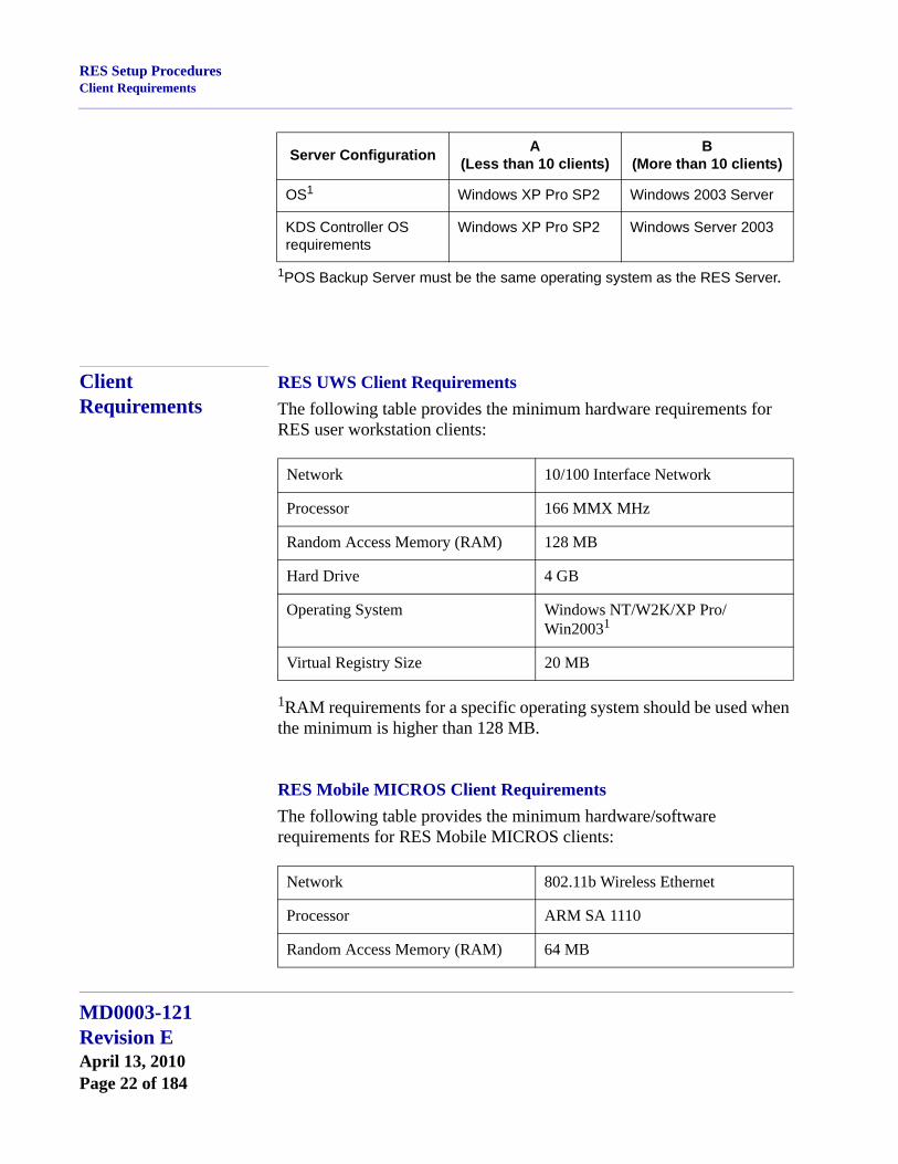
RES UWS Client RequirementsThe following table provides the minimum hardware requirements for RES user workstation clients:
1RAM requirements for a specific operating system should be used when the minimum is higher than 128 MB.
RES Mobile MICROS Client RequirementsThe following table provides the minimum hardware/software requirements for RES Mobile MICROS clients:
OS1 Windows XP Pro SP2 Windows 2003 Server
KDS Controller OS requirements
Windows XP Pro SP2 Windows Server 2003
Server Configuration A(Less than 10 clients)
B(More than 10 clients)
Network 10/100 Interface Network
Processor 166 MMX MHz
Random Access Memory (RAM) 128 MB
Hard Drive 4 GB
Operating System Windows NT/W2K/XP Pro/Win20031
Virtual Registry Size 20 MB
Network 802.11b Wireless Ethernet
Processor ARM SA 1110
Random Access Memory (RAM) 64 MB
MD0003-121Revision EApril 13, 2010Page 22 of 184
RES Setup ProceduresBefore Running Server Setup
1PPC 2000, if not using Manager Procedures.2Download available on the Microsoft® website (www.microsoft.com).
Before Running Server Setup
The section describes activities required prior to running setup for RES Versions 4.0 or higher.
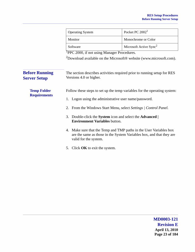
Temp Folder Requirements
Follow these steps to set up the temp variables for the operating system:
1. Logon using the administrative user name/password.
2. From the Windows Start Menu, select Settings | Control Panel.
3. Double-click the System icon and select the Advanced | Environment Variables button.
4. Make sure that the Temp and TMP paths in the User Variables box are the same as those in the System Variables box, and that they are valid for the system.
5. Click OK to exit the system.
Operating System Pocket PC 20021
Monitor Monochrome or Color
Software Microsoft Active Sync2
MD0003-121Revision E
April 13, 2010Page 23 of 184
RES Setup ProceduresBefore Running Server Setup
Database Rebuilds On rare occasions, the system fails when attempting to upgrade the database from RES 3.x to RES 4.x. Typically, this occurs when the installer imports the same database into a number of sites without clearing totals and rebuilding the database first. The problem arises because the Sybase 6 database is trying to autoincrement the trigger for the installation and has reached the maximum value allowed for the data type.
To avoid this problem, MICROS recommends rebuilding the database prior to running the RES 4.x installation. Since RES 4.x includes an upgrade to Sybase 9, the database cannot be corrected in a version 4.x site. To fix it, a copy of the 3.x database will have to be rebuilt on a RES 3.2 before it can be imported and updated on the RES 4.x system.
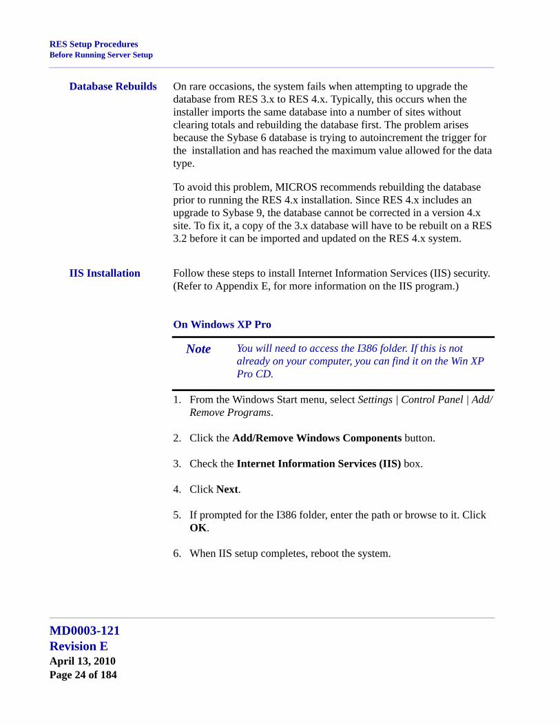
IIS Installation Follow these steps to install Internet Information Services (IIS) security. (Refer to Appendix E, for more information on the IIS program.)
On Windows XP Pro
1. From the Windows Start menu, select Settings | Control Panel | Add/Remove Programs.
2. Click the Add/Remove Windows Components button.
3. Check the Internet Information Services (IIS) box.
4. Click Next.
5. If prompted for the I386 folder, enter the path or browse to it. Click OK.
6. When IIS setup completes, reboot the system.
Note You will need to access the I386 folder. If this is not already on your computer, you can find it on the Win XP Pro CD.
MD0003-121Revision EApril 13, 2010Page 24 of 184
RES Setup ProceduresBefore Running Server Setup
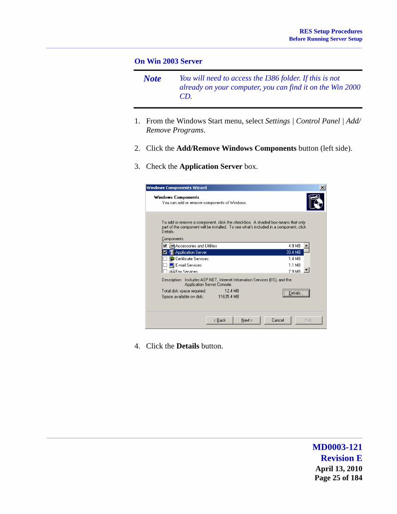
On Win 2003 Server
1. From the Windows Start menu, select Settings | Control Panel | Add/Remove Programs.
2. Click the Add/Remove Windows Components button (left side).
3. Check the Application Server box.
4. Click the Details button.
Note You will need to access the I386 folder. If this is not already on your computer, you can find it on the Win 2000 CD.
MD0003-121Revision E
April 13, 2010Page 25 of 184

RES Setup ProceduresBefore Running Server Setup
5. In the subcomponents list box, make sure that both the ASP.NET and Internet Information Services (IIS) boxes are checked. Click OK.
6. Click Next.
7. If prompted for the I386 folder, enter the path or browse to it. (If this is not already on your computer, it can be found on the Microsoft Windows Server 2003 CD.)
8. Click OK.
9. When IIS setup completes, reboot the system.
If your server is running mymicros.net, you will have to stop the Micros Agent and Micros Watchdog services prior to running RES 4.x Setup:
1. From the Windows Start menu, select Settings | Control Panel | Administrative Tools | Services.
2. Double click on Micros Agent, and click Stop.
3. Double click on Micros Watchdog, and click Stop.
MD0003-121Revision EApril 13, 2010Page 26 of 184
RES Setup ProceduresBefore Running Server Setup
Limitations Please note the following caveats and limitations before running Setup for RES 4.0 or higher:
Due to changes in setup processes, RES no longer supports Repairing or Modifying features. If a problem occurs, sites will have to reinstall the software.
Removing software via the Add/Remove programs applet does not append to the MICROSRESSETUP.LOG on the server.
RES does not support adding applications from the setup program (e.g., Enterprise Office, TMS), once a service pack or hotfix has been applied. To do this, users will have to remove and reinstall the software.
MD0003-121Revision E
April 13, 2010Page 27 of 184

RES Setup ProceduresRunning Server Setup
Running Server Setup
MICROS provides two methods for running RES Setup on a server —interactive and non-interactive. The most common method is the interactive (attended) mode, which provides a series of questions and options to guide you toward successful installation of the software.
The non-interactive (unattended) method procedurally functions as an interactive session, but uses a pre-configured response file to answer the system queries presented during installation. This method is intended for use by customers with large rollout requirements. Its purpose is to ensure a uniform installation across locations.
About the Process Before RES 4.x can be installed, the server must meet the minimum requirements for third-party applications (e.g., Sybase Adaptive Server, Crystal Reports, etc.) that are integral to RES operations. A list of these programs is provided on page 15.
To assist the user, the MICROS setup process has been divided into two installation programs. A separate CD is provided for each:
Prerequisites — Installs or upgrades all of the necessary third-party applications. This should be done first.
RES — Installs or upgrades the selected RES application files and updates the MICROS database.
Please note that a successful installation requires the two setup programs to have compatible version/build numbers. In other words, to ensure that RES 4.8 installs properly, the user must first load the 4.6 Prerequisites.
Follow the steps below to install the system software on a RES Server PC. Remember, if you are loading RES 4.0 or higher on a system that previously had a version of RES installed, you must first remove the older version of RES. Instructions on removing RES can be found in this document, beginning on page 40.
MD0003-121Revision EApril 13, 2010Page 28 of 184
RES Setup ProceduresRunning Server Setup
Installing the Prerequisites
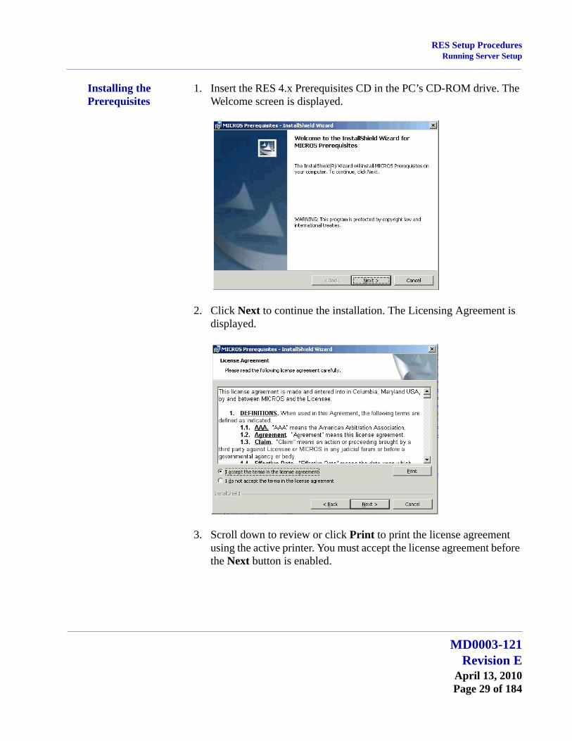
1. Insert the RES 4.x Prerequisites CD in the PC’s CD-ROM drive. The Welcome screen is displayed.
2. Click Next to continue the installation. The Licensing Agreement is displayed.
3. Scroll down to review or click Print to print the license agreement using the active printer. You must accept the license agreement before the Next button is enabled.
MD0003-121Revision E
April 13, 2010Page 29 of 184
RES Setup ProceduresRunning Server Setup
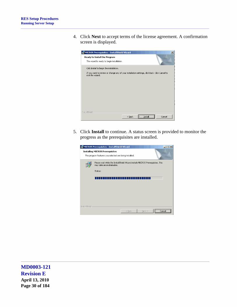
4. Click Next to accept terms of the license agreement. A confirmation screen is displayed.
5. Click Install to continue. A status screen is provided to monitor the progress as the prerequisites are installed.
MD0003-121Revision EApril 13, 2010Page 30 of 184
RES Setup ProceduresRunning Server Setup
6. If no problems are encountered, the system will display a screen when the installation has been completed successfully. Press Finish to exit the setup program.
Note When upgrading a previous 4.x installation, a problem may arise with the previously installed prerequisite files. This is very rare.
If this occurs, the system will prompt you to remove and reinstall the prerequisites. To do this, you must uninstall the RES release BEFORE uninstalling the prerequisites.Once all files are removed, you can install the newer versions of each.
MD0003-121Revision E
April 13, 2010Page 31 of 184
RES Setup ProceduresRunning Server Setup
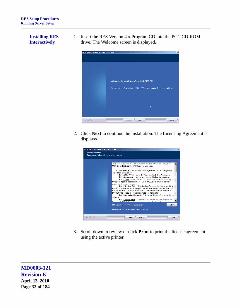
Installing RES Interactively
1. Insert the RES Version 4.x Program CD into the PC’s CD-ROM drive. The Welcome screen is displayed.
2. Click Next to continue the installation. The Licensing Agreement is displayed.
3. Scroll down to review or click Print to print the license agreement using the active printer.
MD0003-121Revision EApril 13, 2010Page 32 of 184
RES Setup ProceduresRunning Server Setup
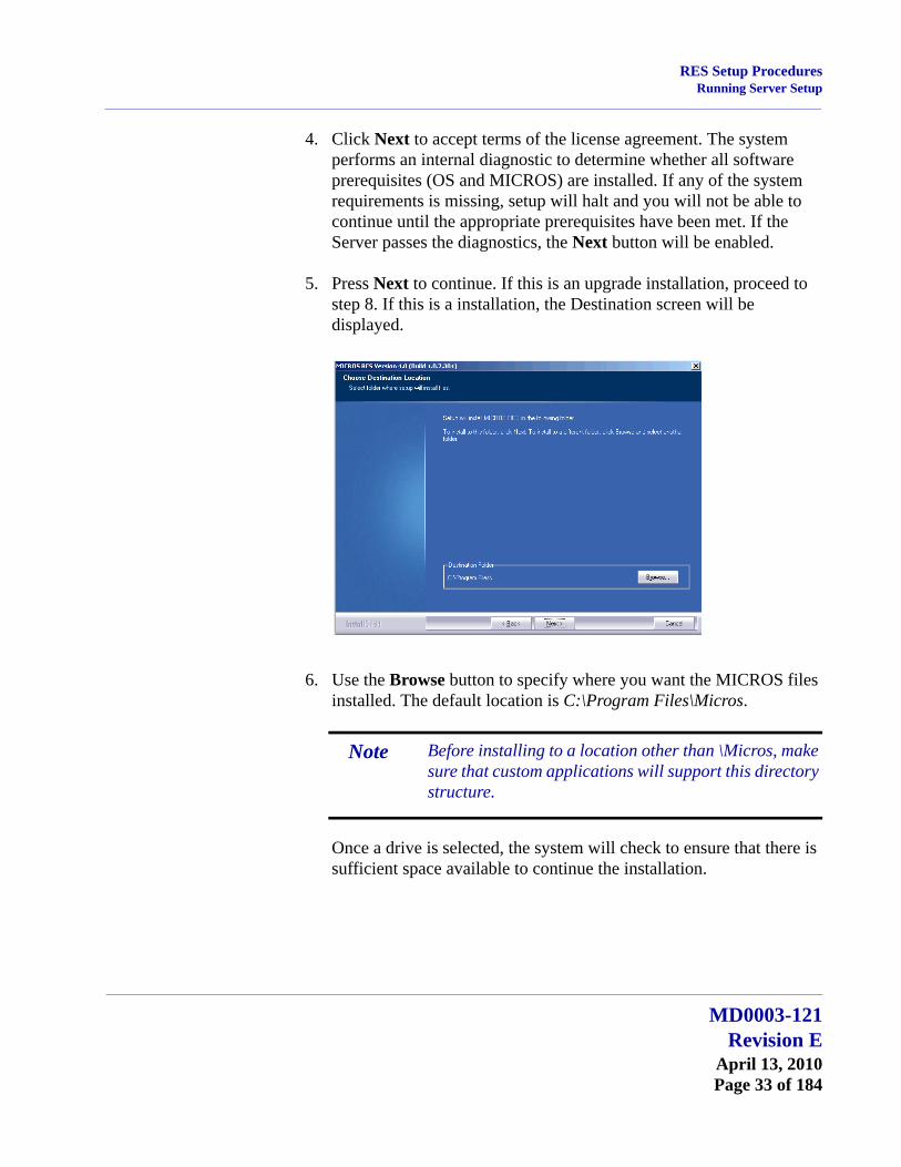
4. Click Next to accept terms of the license agreement. The system performs an internal diagnostic to determine whether all software prerequisites (OS and MICROS) are installed. If any of the system requirements is missing, setup will halt and you will not be able to continue until the appropriate prerequisites have been met. If the Server passes the diagnostics, the Next button will be enabled.
5. Press Next to continue. If this is an upgrade installation, proceed to step 8. If this is a installation, the Destination screen will be displayed.
6. Use the Browse button to specify where you want the MICROS files installed. The default location is C:\Program Files\Micros.
Once a drive is selected, the system will check to ensure that there is sufficient space available to continue the installation.
Note Before installing to a location other than \Micros, make sure that custom applications will support this directory structure.
MD0003-121Revision E
April 13, 2010Page 33 of 184

RES Setup ProceduresRunning Server Setup
7. Press Next to continue. The Features selection screen is displayed.
8. Check the components to be installed from the options listed. RES Infrastructure and RES POS Applications are required; all other selections are optional and may be chosen individually or by ‘parent’ feature. Setup will only install the selected items.
If this is an upgrade, the system will preselect all previously installed applications. You may add/remove selections before continuing. A brief description is provided as each application is selected.
The space required for installation and what is available on the drive are displayed at the bottom of the screen.
MD0003-121Revision EApril 13, 2010Page 34 of 184
RES Setup ProceduresRunning Server Setup
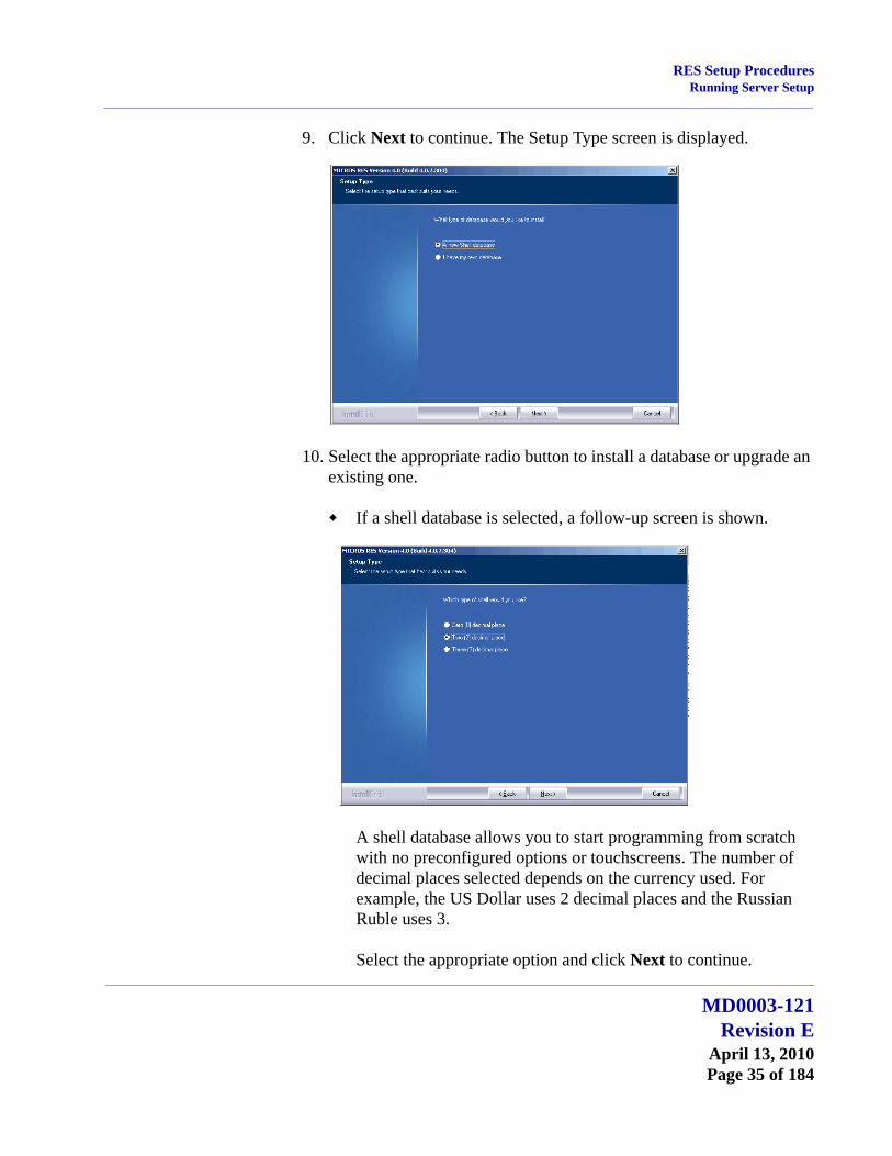
9. Click Next to continue. The Setup Type screen is displayed.
10. Select the appropriate radio button to install a database or upgrade an existing one.
If a shell database is selected, a follow-up screen is shown.
A shell database allows you to start programming from scratch with no preconfigured options or touchscreens. The number of decimal places selected depends on the currency used. For example, the US Dollar uses 2 decimal places and the Russian Ruble uses 3.
Select the appropriate option and click Next to continue.
MD0003-121Revision E
April 13, 2010Page 35 of 184

RES Setup ProceduresRunning Server Setup
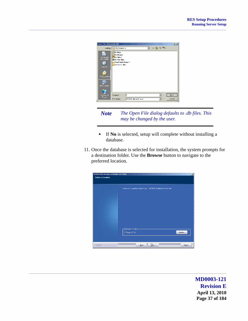
If updating an existing database, a different screen is displayed, asking if you want setup to copy your database in during installation or if you will do this manually at a later time.
If Yes is selected, the Select User’s database screen is displayed, asking for the database location. Use the Browse button to display a standard Open File dialog box and navigate to it.
MD0003-121Revision EApril 13, 2010Page 36 of 184
RES Setup ProceduresRunning Server Setup
If No is selected, setup will complete without installing a database.
11. Once the database is selected for installation, the system prompts for a destination folder. Use the Browse button to navigate to the preferred location.
Note The Open File dialog defaults to .db files. This may be changed by the user.
MD0003-121Revision E
April 13, 2010Page 37 of 184

RES Setup ProceduresRunning Server Setup
12. Click Next to continue. A summary of the selected options is provided for review.
13. Click Next when you are ready to proceed. If any running applications are detected, you will be prompted to close them and resume RES Setup.
14. Reboot the system, if prompted. Depending on the type of installation, this may or may not be required.
MD0003-121Revision EApril 13, 2010Page 38 of 184

RES Setup ProceduresRunning Server Setup
Before Running POS OperationsOnce the software is installed on the system, the default transport encryption key needs to be set before POS Operations will run. To do this:
1. Setup an employee with access privileges for Database Manager (POS Configurator | Employees | Employee Classes | Privileges | Privilege Options \ Allow Encryption Key Change).
2. From the Windows Start menu, select All Programs | MICROS Applications | Utilities | Database | MICROS Database Manager to launch the DM application.
3. Select the Encryption Keys form
4. Check the Change Transport Key option and then press the Change Encryption Keys button.
This will set the default transport encryption key for the system. From here, the system may be configured and run as usual.
MICROS RES Setup Log FileRES Setup creates a log file for both clients and servers. This file documents all events during setup in case some part of the installation is in question and the log is needed for reference. The following table specifies the name and location of this log by device type.
Type Filename Location
Server MicrosPrerequisitesSetup.logMicrosResSetup.logMicrosResPatch.log
\Windows
Win32 Client Setup_log.txt \CALTemp\Packages\Win32RES
WS4 Client Setup_log.txt \CF\CALTemp\Packages\WS4RES
WS4 LX Client Setup_log.txt \CF\CALTemp\Packages\WS4LXRES
MD0003-121Revision E
April 13, 2010Page 39 of 184

RES Setup ProceduresRunning Server Setup
Perl Runtime for QuickbooksBeginning with Version 3.1, RES Setup will no longer automatically install the Perl Runtime program required for use with the Quickbooks interface. The Perl program will still be available on the RES CD. If necessary, it can be added to the appropriate directory as follows:
1. In the MICROS directory, create a Support folder and Utils sub-folder.
2. Copy the Perl.exe from the RES CD Disk \Micros\Support\Utils to the same path on the hard drive.
Remove MICROS Software
From RES 4.0 Hotfix 1 or Higher1. Save the database to a safe location outside of the MICROS tree.
2. From the Windows Start Menu, select Control Panel | Add/Remove Programs or insert the RES CD in the CD-ROM drive to launch setup.
3. When the maintenance screen displays, choose Remove and click Next.
4. After the Remove process is complete, click Yes at the prompt to reboot the system.
WS5 Client Setup_log.txt \CF\CALTemp\Packages\WS5RES
RDC Client Setup_log.txt \FS2\CALTemp\Packages\DCRES
HHT Client (Symbol MC50)
Setup_log.txt \Application\CALTemp\Packages\PPCRES
HHT Client (Symbol MC70)
Setup_log.txt \Application\CALTemp\Packages\PPC70RES
Type Filename Location
MD0003-121Revision EApril 13, 2010Page 40 of 184

RES Setup ProceduresRunning Server Setup
5. Open the Windows Explorer and save any custom files, reports, etc. from the \Micros tree to another location. Delete the \Micros tree.
6. Go to the Control Panel | System |Advanced | Environmental Variables. Delete the Micros_Current_Installation variable.
7. Open Regedit and go to HKLM\Software. Delete the MICROS hive.
8. Reboot the PC.
Note Be sure to save the license codes first. Then use regedit to delete HKLM\Software\Micros.
Although all path information created by RES 4.0 is removed, some parameters left over from previous versions can be missed. Be sure to check and manually delete any MICROS path information, especially if you intend to reinstall RES to a (letter) drive location.
MD0003-121Revision E
April 13, 2010Page 41 of 184

RES Setup ProceduresRunning Server Setup
From RES 4.x Clients (XP and Higher)1. From the Windows Start Menu, select Control Panel | Add/Remove
Programs. Highlight and remove Win32 CAL client.
2. Select Services and stop all MICROS services.
3. Open the Windows Explorer and save any custom files, reports, etc. from the \Micros tree to another location. Delete the \Micros tree.
4. In the Registry, go to My Computer\HKey_Local_Machine\Software\ and delete the entire MICROS hive.
5. In the Registry, go to My Computer\HKey_Local_Machine\System\ CurrentControlSet\Services and delete the following:
dbUpdateServer
MICROS Backup Server
MICROS CAL Client
MICROS Credit Card Server
MICROS ILDS Server
MICROS Interface Server
MICROS KDSController
MICROS Print Controller
MICROSDesk
srvConnAdvisor
srvMDSHTTPService
6. Reboot the client.
MD0003-121Revision EApril 13, 2010Page 42 of 184

RES Setup ProceduresRunning Server Setup
From RES 3.2 ServerFollow these steps to remove MICROS software from a server running Version 3.2 or lower:
1. From the Windows Start Menu, select Programs | MICROS Applications | MICROS Control Panel to launch the interface.
2. Click the button to set the Restaurant to OFF.
3. From the Windows Start Menu, select Settings | Control Panel | Administrative Tools | Services. Stop all MICROS services, including those not installed by RES GR. Specifically:
MICROS 3700 System
MICROS Caller ID Service
MICROS Distributed Service Manager
MICROS Secure Desktop
MICROS LM Com Scheduler
and the non-RES services:
ValueLink, Watchdog, Agent, etc.
4. Select Add/Remove Programs. Highlight and remove all MICROS programs (e.g., EM, ValueLink) except for RES. (RES will be removed in Step 11.)
5. (Optional) If ValueLink is installed, open Windows Explorer and navigate to the WinNT\system32 folder. Save the vlink.cfg file to a safe location.
6. Open a DOS window. From the command line, navigate to the \MICROS\res\pos\bin directory. Enter the following commands to remove the Connection Advisor service:
connadvisor –uninstall
connadvisor –unregister
7. Select Start | Run | Regedit to open the Registry.
MD0003-121Revision E
April 13, 2010Page 43 of 184
RES Setup ProceduresRunning Server Setup
8. Go to My Computer\HKey_Local_Machine\System\Current ControlSet\Services and delete those MICROS services that were not installed by RES GR.
9. Go to HKey_Local_Machine\Software\MICROS\Common and highlight LicenseManager. From the menu bar, select Registry | Export Registry File... to save the license codes to a safe location, outside the MICROS tree.
10. Open the Windows Explorer and navigate to the MICROS\ Database\Data folder. Save the micros.db and micros.log to safe location.
11. Return to Settings | Control Panel | Add/Remove Programs to remove the MICROS RES 3.2 software.
12. Go back to Windows Explorer and manually delete the MICROS tree.
13. In the Registry, go to My Computer\HKey_Local_Machine and delete the following:
Software\MICROS
Software\Borland
Software\ODBC\odbc.ini\micros
Software\ODBC\odbc.ini\microsOld
Software\ODBC\odbc.ini\microsSetup
Software\ODBC\odbc.ini\ODBC Data Sources
Software\ODBC\odbcInst.ini\Adaptive Server Anywhere 6.0
Software\ODBC\odbcInst.ini\Adaptive Server Anywhere 6.0 Translator
Software\ODBC\odbcInst.ini\ODBC Drivers\Adaptive Server Anywhere 6.0
Software\ODBC\odbcInst.ini\ODBC Translators\Adaptive Server Anywhere 6.0 Translator
System\CurrentControlSet\Services\3700d
MD0003-121Revision EApril 13, 2010Page 44 of 184

RES Setup ProceduresRunning Server Setup
System\CurrentControlSet\Services\Micros Backup Server
System\CurrentControlSet\Services\Micros CAL Service
System\CurrentControlSet\Services\CISERVICE
System\CurrentControlSet\Services\svcCashManager
System\CurrentControlSet\Services\MicrosCashManagementComServer
System\CurrentControlSet\Services\srvConnAdvisor
System\CurrentControlSet\Services\Micros Database Service
System\CurrentControlSet\Services\DbUpdateServer
System\CurrentControlSet\Services\MICROS Distributed Service Manager
System\CurrentControlSet\Services\svcCOMScheduler
System\CurrentControlSet\Services\srvMDSHTTPService
System\CurrentControlSet\Services\MicrosDesk
System\CurrentControlSet\Services\SQLANYs_sql (Server Name)
14. Reopen the Control Panel and select System | Advanced | Environment variables. Delete the Micros_Current_Installation entry.
(Note: If the system was at GR, this would already be removed. This step is only necessary if a patch had been installed.)
15. Reboot the PC.
MD0003-121Revision E
April 13, 2010Page 45 of 184
RES Setup ProceduresRunning Server Setup
From RES 3.2 ClientsFollow these steps to remove MICROS software from a client running Version 3.2 or lower:
1. From the Windows Start Menu, select Settings | Control Panel | Administrative Tools | Services. Stop the following MICROS services:
MICROS 3700 System
MICROS Backup Server
MICROS Connection Advisor (only present after SP1)
MICROS DB Update Service
MICROS MDS HTTP Service
MICROS Secure Desktop
2. Select Add/Remove Programs. Highlight and remove MICROS res3000 v3.2. (Note: There may be multiple instances of this program listed; if so, remove them all.)
3. Open a DOS window. From the command line, navigate to the \MICROS\res\pos\bin directory. Enter the following commands to remove the Connection Advisor service:
connadvisor –uninstall
connadvisor –unregister
4. Open Windows Explorer and manually delete the MICROS tree.
5. Select Start | Run | Regedit to open the Registry.
6. Go to My Computer\HKey_Local_Machine and delete the following:
Software\MICROS
Software\Borland
Software\ODBC\odbc.ini\micros
Software\ODBC\odbc.ini\microsOld
MD0003-121Revision EApril 13, 2010Page 46 of 184
RES Setup ProceduresRunning Server Setup
Software\ODBC\odbc.ini\microsSetup
Software\ODBC\odbc.ini\ODBC Data Sources
Software\ODBC\odbcInst.ini\Adaptive Server Anywhere 6.0
Software\ODBC\odbcInst.ini\Adaptive Server Anywhere 6.0 Translator
Software\ODBC\odbcInst.ini\ODBC Drivers\Adaptive Server Anywhere 6.0
Software\ODBC\odbcInst.ini\ODBC Translators\Adaptive Server Anywhere 6.0 Translator
System\CurrentControlSet\Services\3700d
System\CurrentControlSet\Services\Micros Backup Server
System\CurrentControlSet\Services\srvConnAdvisor
System\CurrentControlSet\Services\DbUpdateServer
System\CurrentControlSet\Services\srvMDSHTTPService
System\CurrentControlSet\Services\MicrosDesk
System\CurrentControlSet\Services\SQLANYs_sql (Client Name)
7. Reopen the Control Panel and select System | Advanced | Environment variables. Delete all MICROS environment variables (e.g., ASANY, SqlAny, Micros_current version, etc.).
8. Reboot the PC.
MD0003-121Revision E
April 13, 2010Page 47 of 184

RES Setup ProceduresRunning Server Setup
Move MICROS to a DriveThis procedure requires the use of a 4.x Demo database. The database must use all default settings (Encryption Keys and Passwords) and the process must be initiated by an employee who is privileged to restore a database (POS Configurator | Employees | Employee Classes | Privileges |Privilege Options | Allow DB Restore).
1. Open the Database Manager utility and click the Backup Database option to open the form.
2. Check the Backup Database check box and click Run Backup to create the appropriate backup files.
3. Save a copy of the most recent database archive \Micros\Database\Data\Backup\Archive \ Micros_{Date}.mbz to a location outside the \MICROS tree.
4. Remove RES 4.x using the direction provided in this manual, beginning on page 40.
5. Install RES 4.0 or higher. When prompted, select the options to have setup install your 4.0 or higher Demo database. This includes specifying a database location.
6. When Installation is complete, reopen Database Manager and sign-in as a privileged Employee.
7. Select the Restore Database button. In the popup window, select the archived database saved in Step 2 above.
8. Run Database Manager and select the Rebuild\Update option.
9. Check the option Update\Upgrade Database and click Run.
MD0003-121Revision EApril 13, 2010Page 48 of 184

RES Setup ProceduresRunning Client Setup
Running Client Setup
This section provides instructions for installing RES on both hard-drive and hand-held clients.
Hard-Drive Client Installation
As of RES 4.0, hard-drive clients use the Client Application Loader (CAL) technology to locate, install, and maintain the most up-to-date programs implemented on the RES Server.
For Windows Clients1. Verify that the appropriate version of Windows is installed.
2. Verify that the appropriate version of CAL Client is installed.
3. Verify that Internet Explorer 6.0 sp1 (or higher) is installed.
4. Verify that.NET Framework 1.1 sp1 is installed.
Since workstations typically do not have a keyboard connected, it is necessary to configure the system to perform an auto-admin logon. The configured user does NOT need to have administrative privileges. The user does need to be a member of the Power User group. MICROS recommends that you DO NOT use the legacy microssvc user for this purpose.
5. Enable the Windows Autologon feature as a valid Windows user.
Select Start | Run | Regedit.
Go to My Computer\HKEY_LOCAL_MACHINE\ Software\Microsoft\Windows NT\CurrentVersion\ Winlogon.
Verify that the following three STRING values are added/modified:
AutoAdminLogon = 1
DefaultUserName = User name of your choice
DefaultPassword = Password of the user you choose
MD0003-121Revision E
April 13, 2010Page 49 of 184

RES Setup ProceduresRunning Client Setup
6. Close Regedit and reboot the workstation. This Windows client should automatically login after the above steps are completed.
7. Plug into the MICROS network and boot up the client.
8. Use the CAL configuration to link this client into the system. The client application loader should start downloading the RES software right after the configuration is complete.
Mobile MICROS (MMH) Client Installation
RES supports the following handheld devices:
Symbol 2800, supported in RES v. 4.0 General Release and greater
Symbol 8800, supported in RES v. 4.0 General Release and greater
Symbol MC50, supported in RES v. 4.0 General Release and greater
Motorola MC55, supported in RES v. 4.4 and greater
Symbol MC70, supported in RES v. 4.4 and greater
Fujitsu BPAD, supported in RES v. 4.0 General Release and greater
For general setup information, see “Mobile MICROS General Information” on page 51.
Note When configuring the CAL Client application path, the user can select the drive, but the path should not be specified. An error will occur if a non-root application path is entered (e.g. C:\MICROSAPPS).
MD0003-121Revision EApril 13, 2010Page 50 of 184

RES Setup ProceduresRunning Client Setup
Mobile MICROS General InformationNote that in some cases it may be necessary to enter the Server's IP address as the client's Default Gateway.
Using a Static IP AddressSpecial consideration is required when using a Static IP address.
It has been determined that when using Windows Mobile 5.0 and higher, CAL has trouble setting a static IP address from within the “Choose a Client” window on a re-configuration. DHCP has no known CAL-related issues.
As a workaround, MICROS Systems, Inc. has developed a separate utility, StaticProfile.exe, to be used when implementing Static IP addresses with the Symbol MC55 and MC70. This utility is not necessary if you never plan to reconfigure the device once it is setup.
The StaticProfile.exe utility is located on the \Application folder of the Symbol MC55 and MC70. If StaticProfile.exe does not exist in the \Application folder of the MC55 or MC70, use an SD card or active Sync to copy it there. You may contact the MICROS Systems, Inc. help desk and request copy of the “StaticProfile.exe” utility via email.
Follow the instructions below:
1. Once StaticProfile.exe is in the \Application folder, tap it to launch.
2. Tap the StaticProfile.exe. A message will display “This process will Reboot the Device.” Click OK.
3. The Application opens.
4. In the “Profile Name” box, enter the SSID of your Wireless Infrastructure. Note: The profile name is case sensitive.
5. In the “IP Address Box,” enter the static IP address of your MC55 or MC70.
6. In the “Subnet Mask” box, enter the subnet address of your network.
MD0003-121Revision E
April 13, 2010Page 51 of 184

RES Setup ProceduresRunning Client Setup
7. In the “Encryption” box, select the encryption method appropriate to your Wireless security.
8. If using a passphrase, enter the passphrase into the “Pass key” box.
9. If using a Hex Key, enter the hex key into the “Pass Key” box.
10. In the “Key Index” box, enter the key number.
11. If using the 802.11d internationalization standard, choose your “Country Code.”
12. Click [Create] and the StaticProfile utility will reboot the MC55 or MC70.
13. Once the new static Profile is created, proceed to use CAL, even when changing an IP address.
When the Access Point Becomes Out of Range To ensure the Mobile MICROS device does not connect to unwanted access points when it is out of range of the access point, follow the steps below:
1. After configuring the wireless network, navigate to the MMH desktop and tap the network icon in the bottom right corner of the screen.
2. Select WAN Profiles.
3. Move your main profile to the top of the list.
4. Move any secondary profiles you may wish to use just below the Main profile.
5. Delete all WAN profiles that you do NOT wish to use.As a secondary option, you could just Disable the other profiles, if you want to use them in the future.
Note When reconfiguring CAL on hand held devices, in some cases it may be necessary to enter the Server's IP address as the client's Default Gateway.
MD0003-121Revision EApril 13, 2010Page 52 of 184
RES Setup ProceduresRunning Client Setup
Workstation 4 CAL Client Installation
Support for WS4 clients was added in the RES 3.2 release. WS4 devices use the Client Application Loader (CAL) technology to locate, install, and maintain the most up-to-date software programs implemented on the server.
Follow these steps to install a workstation:
1. Unpack the device and connect to the system LAN.
2. When the device is powered up for the first time, the CAL looks for and displays a list of CAL Servers on the network.
3. Select a CAL Server and click OK. A list of the Server’s available workstations is displayed. Workstations configured but not assigned are placed at the top of the list.
4. Select an available workstation and click OK. The system will automatically load the workstation ID and network configuration fields. This may be changed manually, if desired.
5. Save the configuration. The system will automatically transfer the required application software.
6. Once all software has been downloaded, the 3700 POS and/or KDS applications will start.
RDC Client Installation
Support for Restaurant Display Controller (RDC) clients was added in the RES 3.2 release. RDC devices use the Client Application Loader (CAL) technology to locate, install, and maintain the most up-to-date software programs implemented on the server
Follow these steps to install an RDC Client:
1. Unpack the device, attach a keyboard or bump bar, and connect to the system LAN.
Note For more information on the WS4, please refer to the Workstation 4 Setup Guide, available on the MICROS website under Products | Hardware Solutions | Documentation.
MD0003-121Revision E
April 13, 2010Page 53 of 184

RES Setup ProceduresInstalling Point Releases and Hotfixes
2. When the device is powered up for the first time, the CAL looks for and displays a list of CAL Servers on the network.
3. Use the Up/Down Arrows on the bump bar or keyboard to scroll the list and highlight the required server. Click OK to accept the entry.
Once a server is identified, a list of the RDC workstations is displayed, along with their current status. To be included on the list, the device must have been added to the system through POS Configurator.
4. Use the Up/Down Arrows on the keyboard or bump bar to highlight a selection and press Save/OK to accept. The system will automatically load the workstation ID and network configuration fields. This may be changed manually, if desired.
5. Save the configuration. The system will automatically transfer the required application software.
6. Once all software has been downloaded, KDS applications will start.
Installing Point Releases and Hotfixes
This section describes the requirements and procedures for installing an upgrade to the RES Version 4.0 or higher software.
Site Requirements Review
With RES Version 4.0 or higher, the installation process comprises two parts: a Prerequisite file and a RES setup file. Updates to these files are made independently of each other. Therefore, running the Prerequisites installation may not be necessary for every RES patch release.
Important POS Operations will no longer start if the site is not PCI-compliant. Make sure that the proper steps are taken to achieve compliance. For detailed information regarding PCI-compliance, see the PCI Compliance Verified as the Site section beginning on page 179.
MD0003-121Revision EApril 13, 2010Page 54 of 184
RES Setup ProceduresInstalling Point Releases and Hotfixes
Before You Begin Make sure that Script Locking is turned off when using Norton Anti-Virus software, and that all anti-virus software is disabled when running the service pack.
If using McAfee VirusScan 8.0, disable the Script Stopper software located in the directory under McAfee Security Center | Virus Scan | Configure virus scan options | Advanced.
When upgrading on a RES system where the MICROS Portal is installed, be sure to manually shut down the Micros Agent and Micros Watchdog services. Failure to shut down these Portal-related services may result in a system lockup during database conversion.
RES Setup creates 2 log files, MicrosResPatch.log, and MicrosMainPatch.log, that are both located on the RES Server in the Windows folder. The MicrosResPatch.log documents the pre and post installation procedures and the microsmainpatch.log covers the installation of the files. The client setup log is located in the CALTemp folder on each client and is called Setup_log.txt.
Users who have modified the Global.css file (allowing Manager Procedures to support double-byte characters) will need to restore the original version of this file (located in the Micros\common\ ManagerProcAsp folder) before installing the Service Pack. Failure to do so will prevent the Service Pack from running. Once the installation is complete, the modified file can be copied back to the directory.
When installing a Service Pack, the user must log in with Administrator rights both before running the patch and after the server reboots.
Sites using Product Management (PM) software should reconcile and approve all packing slips and invoices prior to applying the service pack upgrade. Otherwise, the system may not prevent a user from selecting and modifying receipts in a closed period.
MD0003-121Revision E
April 13, 2010Page 55 of 184

RES Setup ProceduresInstalling Point Releases and Hotfixes
Verify that the prerequisites and versions of RES meet the requirements for patch installation. Prior to installation, the patch will check the prerequisites and RES version in the registry. The patch will not run if the version string does not match. If the patch is run a second time the error message, “Patch terminated by custom action,” will display. To determine the specific action that stopped the patch, users can scroll to the bottom of WinDir\MicrosRESPatch.log.
Keep in mind that after installing a patch, attempts to perform an incremental database backup (e.g., calling DM -T) will be unsuccessful. This is because a full database backup must be performed before incremental backups can occur.
MD0003-121Revision EApril 13, 2010Page 56 of 184
RES Setup ProceduresInstalling Point Releases and Hotfixes
Installation and Setup
Follow these steps to install the patch:
Stop the System1. In the MICROS Control Panel, set the Restaurant to OFF.
2. Make sure all hard-drive clients are at system closed.
3. Close all applications prior to running the Service Pack, including the MICROS Control Panel.
4. If you have altered any RES core files, you must replace them with the original versions before proceeding. Failure to do so will not stop the patch, but some files may not get updated.
Apply the Service Pack1. Create a temporary working folder on your server’s hard drive. Make
sure that you have 1 GB of available space on the hard drive where the application is stored and the drive where Windows resides.
2. Copy the file to the temporary folder on the RES Server. Double-click to decompress the files from this self-extracting executable. A DOS window will display during the Service Pack installation. The Service Pack will install automatically, copying the files to the appropriate directories.
Note If you are running the MICROS Secure Desktop on Win32 clients, you must manually shut down and disable the service before running the hot fix.
Reset the service to “automatic” after successfully completing client installation and then reboot the clients.
Note Prior to installation the system is scanned for escalation files (files with the extension .prepatchrestore). If one is found (e.g. Ops.exe.prepatchrestore), the .prepatchrestore extension will be deleted, and the patch will be able to update the escalated file.
MD0003-121Revision E
April 13, 2010Page 57 of 184

RES Setup ProceduresInstalling Point Releases and Hotfixes
3. The server will automatically reboot.
Update the Clients Hard-Drive ClientsIn RES 4.x hard drive clients use CAL to update just like WS4’s do. After the server reboots, all clients will automatically upgrade. They will reboot several times during the upgrade process.
WS4, WS4 LX, WS5, and RDC ClientsClients will use CAL to automatically update to the current version of RES. Once the server has rebooted, CAL will start the upgrade process. This should occur within 5 minutes of the Server rebooting.
Mobile MICROS ClientsThe PPC clients (e.g. MC50) use CAL to get updated. All other Mobile MICROS clients will use the POS Loader to automatically update to the current version of RES.
Once the server has rebooted, the POS Loader will start the upgrade process. This should occur within 5 minutes of the server rebooting. If the upgrade process does not start, cold boot the unit.
Once the upgrade is complete, cold boot the unit.
When a RES 4.0 Server is patched, all clients except for the Symbol 8800 will be updated automatically. The Symbol 8800 will need to be rebooted or re-cradled after the server has been patched in order to receive the update.
Note If during device setup the user accidentally taps outside of the active window, the window will disappear. If this occurs the user must perform a warm reboot of the system by pressing the OFF key, and restart the setup process.
MD0003-121Revision EApril 13, 2010Page 58 of 184
RES Setup ProceduresInstalling Point Releases and Hotfixes
PCI Compliance Verified at System StartupThe system will now verify that the site is compliant with the PCI Credit Card Data Security Standard upon starting POS Operations. This will occur if the following conditions are met:
The site is not in demo mode, and
At least 1 tender is linked to a non-demo driver.
If the site is not compliant, POS Operations will not start and an error message will appear. The text in the log will indicate the reason why the site was deemed to be non-PCI compliant. All error messages and steps to correct them are listed in the Error Messages section on page 61.
The system uses the following criteria to determine a site’s PCI-compliance:
DBA database password is not set to the default.
MICROS database password is not set to the default.
Database file encryption passphrase is not set to the default.
Sensitive data passphrase is not set to the default.
Complex Security enabled at the site.
Security is configured as specified in the RES Version 4.3 Hotfix 1 or Higher Payment Application Data Security Standard (PA-DSS) Implementation Guide, MD0003-117. These settings include:
Days Until Expiration (POS Configurator | System | Restaurant | Security). This field specifies the number of days that a password may remain active before it must be changed. This value cannot be greater than 90 days.
Minimum Password Length (POS Configurator | System | Restaurant | Security). Enter the minimum number of characters required for the password length. This field must be set to a minimum of 7.
MD0003-121Revision E
April 13, 2010Page 59 of 184

RES Setup ProceduresInstalling Point Releases and Hotfixes
Password Repeat Interval (POS Configurator | System | Restaurant | Security). Enter the number of different passwords that must be used before an old password can be repeated. This option must be set to a minimum of 4.
Require Alphanumeric Passwords (POS Configurator | System | Restaurant | Security). Select this option to require passwords to contain letters and numbers. This option must be enabled.
Maximum Allowed Failed Logins (POS Configurator | System | Restaurant | Security). Enter the number of failed logins that may occur before locking the user out of his/her account. This value cannot be greater than 6.
Maximum Idle Time (POS Configurator | System | Restaurant | Security). Enter the number of minutes an administrative application will remain idle before the application will undo any saved changes and exit, requiring the user to login again. This setting cannot be more than 15 minutes.
Mask Credit Card Number (POS Configurator | Sales | Tender/Media | CC Tender). This option must be enabled to mask all credit card numbers in the database.
Mask Expiration Date (POS Configurator | Sales | Tender/Media | CC Tender). This option must be enabled to mask all credit card expiration dates in the database.
Mask Cardholder Name (POS Configurator | Sales | Tender/Media | CC Tender). When enabled, the cardholder name is masked in all displays, logs, reports, journals, and printouts. This option must be enabled.
MD0003-121Revision EApril 13, 2010Page 60 of 184
RES Setup ProceduresInstalling Point Releases and Hotfixes
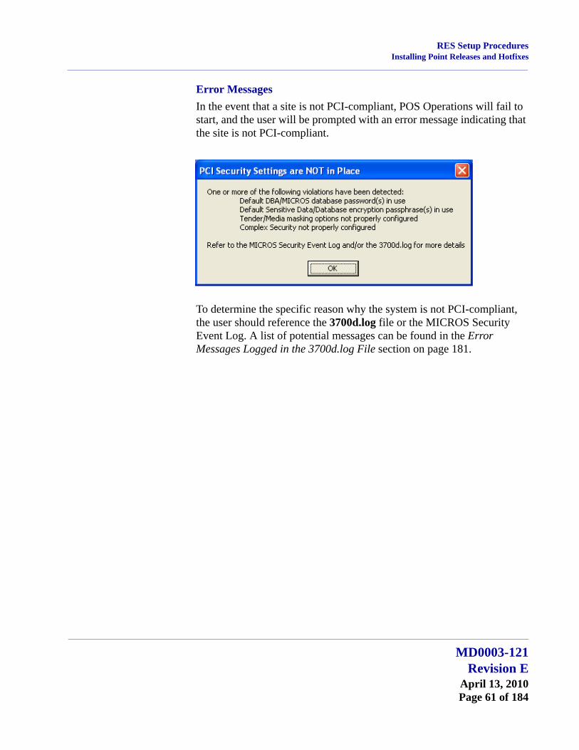
Error MessagesIn the event that a site is not PCI-compliant, POS Operations will fail to start, and the user will be prompted with an error message indicating that the site is not PCI-compliant.
To determine the specific reason why the system is not PCI-compliant, the user should reference the 3700d.log file or the MICROS Security Event Log. A list of potential messages can be found in the Error Messages Logged in the 3700d.log File section on page 181.
MD0003-121Revision E
April 13, 2010Page 61 of 184
Appendix A: SEI KDS Client Hardware SetupServer Connections
Appendix A: SEI KDS Client Hardware Setup
Support for the Select Electronics, Inc. (SEI) hardware platform is available for sites running RES 3.2 or higher. SEI offers an economical alternative to the traditional PC-based KDS system.
SEI KDS runs on the 32-bit OASys processor, which can host up to 4 independent video monitors and 4 2x9 bump bars. An EV1000 video card is required for each monitor connected to the base unit. With multiple units, up to 16 KDS displays can be linked to a single POS server.
Within the RES kitchen, a mix of both SEI KDS and traditional units is allowed.
This section provides information for setup of the SEI KDS hardware only. For additional information on configuring the RES KDS clients, refer to SEI KDS Client Support topic in the KDS Online Feature Reference Manual.
Server Connections OASys units can be connected to the POS server in two ways:
1. RS232 (com port) — This method allows the OASys unit to use all four slots for SE video cards (i.e., four KDS clients supported per OASys unit.)
2. TCP/IP (Ethernet) — This method uses one of the unit’s four slots for a network card. The other three can be used for SE video cards (i.e., three KDS clients supported per OASys unit.)
Note The OASys KDS includes a duplicate video port with each video card. The duplicate can be connected to a second monitor, allowing 2 monitors to display identical information. Some restrictions may apply. Refer to the vendor’s documentation for more information.
MD0003-121Revision EApril 13, 2010Page 62 of 184
Appendix A: SEI KDS Client Hardware SetupHardware Setup
Hardware Setup SEI OASys offers “out-of-the-box,” plug-n-play hardware that can be set up and ready to go in minutes. This section describes the basic steps needed to assemble and connect the base units, bump bars, video displays, and related cables in preparation for configuring the system.
Before You Begin Before attempting to assemble each SEI OASys unit, assemble the following equipment:
1 OASys Processor Base Unit
1-4 EV1000 or AV1000 Video Cards (one for each KDS display to be linked to the base unit)
1 Ethernet Card (Optional; for connecting to the server via a network)
1-4 Bump Bars (one for each KDS display to be linked to the base unit)
Phillips-head Screwdriver
Flat-head Screwdriver
Copy of the Select Electronics OASys KDS Hardware Installation Manual (Available from their website, http://www.selectelectronics.com/). Refer to this document for background information and clarification of terms.
Warning For your safety and the integrity of the equipment, do not disconnect ANYTHING to the OASys base unit without first disconnecting the power.
MD0003-121Revision E
April 13, 2010Page 63 of 184

Appendix A: SEI KDS Client Hardware SetupHardware Setup
For Ethernet Communication
Follow these steps to set up the hardware for connection to the network server:
1. Using the screwdrivers, remove the cover from the OASys unit.
2. Locate the OASys video cards required for this unit. Cards may be loose or pre-loaded.
3. Set the ID dip switches for each of the video cards. Dip switches indicate the slot where the card resides in the base unit.
4. Load the video cards in their assigned slots.
5. Insert the network card into CN5.
6. Plug in the bump bar. Bump bar IDs should be set to 1 (factory default) for all bump bars.
7. Attach and turn on all monitors.
8. Attach power cable and turn on system. The system starts initializing the monitors, writing first to Monitor 1 and then confirming setup on the rest of the monitors. When complete, confirm that each monitor displays the appropriate video assignment.
9. Disconnect the power and attach a PC Keyboard to the OASys base unit.
10. Plug in power again.
Tip Each video card must be assigned a unique ID # (location) in the base unit. To avoid confusion, MICROS recommends labeling the cards sequentially; where CN2=ID1, CN3=ID2, and CN4=ID3. (CN1 is reserved for the Serial Card.
Note A keyboard must be attached to activate the setup utility.
MD0003-121Revision EApril 13, 2010Page 64 of 184

Appendix A: SEI KDS Client Hardware SetupHardware Setup
11. When the OASys Setup Utility displays, select 1 to enter the base unit configuration.
12. On the Vendors screen, select 9 to go to the next page.
13. Select 5 for MICROS Ethernet. When the prompt “You have selected MICROS Ethernet” displays, select Y to confirm.
14. At the prompt, enter the full IP Address of the base unit.
15. When the full IP address has been typed in, press Enter one more time. At the prompt, select Y to confirm the address.
16. At the prompt, enter the RES System Subnet Mask, using the Enter key to move between IP octets.
17. Press Enter one more and, at the prompt, select Y to confirm the address.
18. The system will ask you to program your ethernet card with specific IRQ (10), I/O Address (0x300) and Half Duplex. Be sure to confirm in later steps that your ethernet card is set up this way.
19. Select Y to continue to the ethernet card setup utility. At this point the system will automatically take you to the Ethernet Adapter Setup and Diagnostic Utility.
20. From the main menu, select View Configuration to review settings. If a change is necessary, select Setup to return to the configuration screens.
21. When all changes are complete, power off the base unit and unplug the keyboard.
22. Plug the ethernet cable into the base unit and power the base unit back on. The base unit will automatically display video assignments on each monitor and be ready for RES KDS client configuration.
Note To move to the next IP octet, press the Enter key.
MD0003-121Revision E
April 13, 2010Page 65 of 184
Appendix A: SEI KDS Client Hardware SetupHardware Setup
For RS232 Communication
Follow these steps to set up the hardware for com port communication:
1. Using the screwdrivers, remove the cover from the OASys unit.
2. Locate the OASys video cards required for this unit. Cards may be loose or pre-loaded.
3. Set the ID dip switches for each of the video cards. Dip switches indicate the slot where the card resides in the base unit.
4. Load the video cards in their assigned slots.
5. Plug in the bump bar. Bump bar IDs should be set to 1 (factory default) for all bump bars.
6. Attach and turn on all monitors.
7. Attach power cable and turn on system. The system starts initializing the monitors, writing first to Monitor 1 and then confirming setup on the rest of the monitors. When complete, confirm that each monitor displays the appropriate video assignment.
8. Disconnect the power and attach a PC Keyboard to the OASys base unit.
9. Plug in power again.
10. When the OASys Setup Utility displays, select 1 to enter the base unit configuration.
11. On the Vendors screen, select 9 to go to the next page.
Tip Each video card must be assigned a unique ID # (location) in the base unit. To avoid confusion, MICROS recommends labeling the cards sequentially; where CN2=ID1, CN3=ID2, CN4=ID3, and CN5=ID4. (CN1 is reserved for the Serial Card.
Note A keyboard must be attached to activate the setup utility.
MD0003-121Revision EApril 13, 2010Page 66 of 184

Appendix A: SEI KDS Client Hardware SetupHardware Setup
12. Select 4 for MICROS RS232. When the prompt “You have selected MICROS RS232” displays, select Y to confirm.
13. When all changes are complete, power off the base unit and unplug the keyboard.
14. Plug the serial cable into the base unit and power the base unit back on. On boot up, the system will display “MICROS RS232 Version.” It will then automatically display video assignments on each monitor and be ready for RES KDS client configuration.
MD0003-121Revision E
April 13, 2010Page 67 of 184

Appendix B: Silent Installation Procedures (Server)Hardware Setup
Appendix B: Silent Installation Procedures (Server)
This appendix provides instructions for setting the system properties required to perform a silent (non-interactive) installation on a system Server.
On a Windows 2003 Server system, attempts to shut down the system will cause a dialog box to display prompting the user to enter a reason for the shutdown. Since user interaction defeats the purpose of a remote install, users will need to turn off the prompting mechanisms before proceeding. To do this:
1. From the Windows menu, select Start | Run.
2. When the dialog box displays, type gpedit.msc and click the OK button. The Group Policy Object Editor is shown.
3. Select Computer Configuration | Administrative Templates | System.
MD0003-121Revision EApril 13, 2010Page 68 of 184
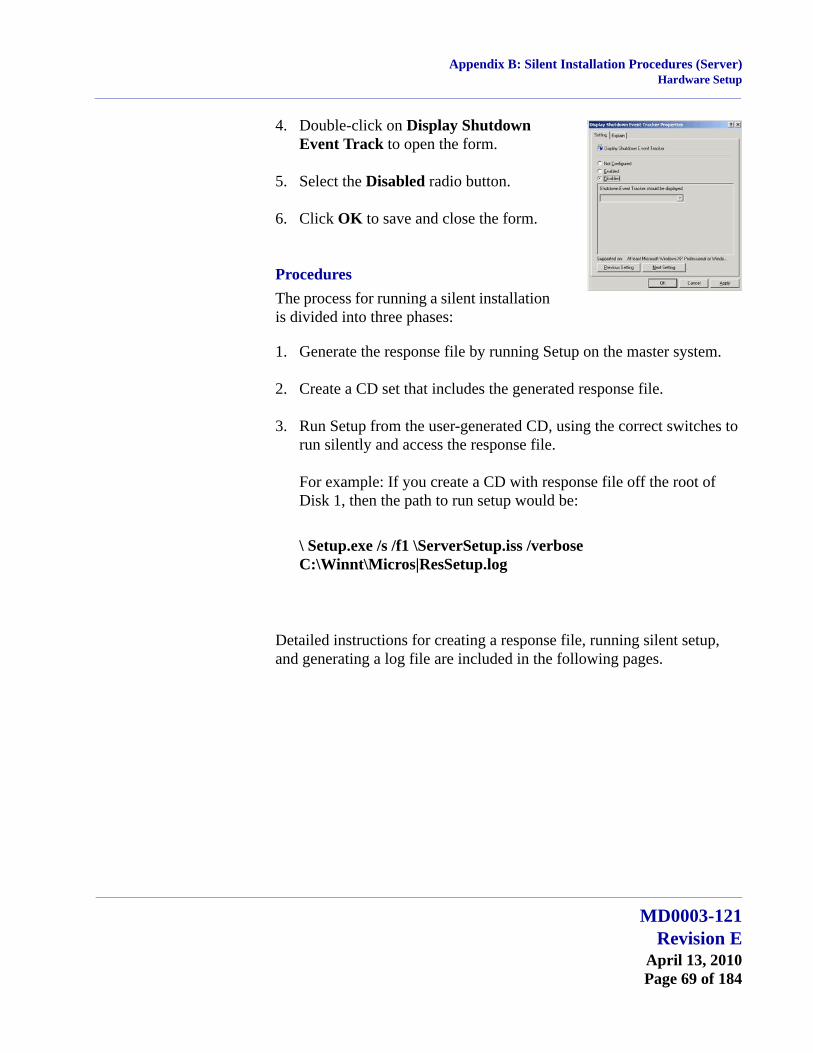
Appendix B: Silent Installation Procedures (Server)Hardware Setup
4. Double-click on Display Shutdown Event Track to open the form.
5. Select the Disabled radio button.
6. Click OK to save and close the form.
ProceduresThe process for running a silent installation is divided into three phases:
1. Generate the response file by running Setup on the master system.
2. Create a CD set that includes the generated response file.
3. Run Setup from the user-generated CD, using the correct switches to run silently and access the response file.
For example: If you create a CD with response file off the root of Disk 1, then the path to run setup would be:
\ Setup.exe /s /f1 \ServerSetup.iss /verbose C:\Winnt\Micros|ResSetup.log
Detailed instructions for creating a response file, running silent setup, and generating a log file are included in the following pages.
MD0003-121Revision E
April 13, 2010Page 69 of 184
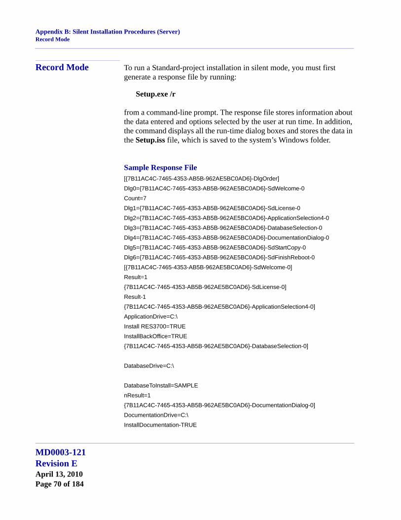
Appendix B: Silent Installation Procedures (Server)Record Mode
Record Mode To run a Standard-project installation in silent mode, you must first generate a response file by running:
Setup.exe /r
from a command-line prompt. The response file stores information about the data entered and options selected by the user at run time. In addition, the command displays all the run-time dialog boxes and stores the data in the Setup.iss file, which is saved to the system’s Windows folder.
Sample Response File[{7B11AC4C-7465-4353-AB5B-962AE5BC0AD6}-DlgOrder]
Dlg0={7B11AC4C-7465-4353-AB5B-962AE5BC0AD6}-SdWelcome-0
Count=7
Dlg1={7B11AC4C-7465-4353-AB5B-962AE5BC0AD6}-SdLicense-0
Dlg2={7B11AC4C-7465-4353-AB5B-962AE5BC0AD6}-ApplicationSelection4-0
Dlg3={7B11AC4C-7465-4353-AB5B-962AE5BC0AD6}-DatabaseSelection-0
Dlg4={7B11AC4C-7465-4353-AB5B-962AE5BC0AD6}-DocumentationDialog-0
Dlg5={7B11AC4C-7465-4353-AB5B-962AE5BC0AD6}-SdStartCopy-0
Dlg6={7B11AC4C-7465-4353-AB5B-962AE5BC0AD6}-SdFinishReboot-0
[{7B11AC4C-7465-4353-AB5B-962AE5BC0AD6}-SdWelcome-0]
Result=1
{7B11AC4C-7465-4353-AB5B-962AE5BC0AD6}-SdLicense-0]
Result-1
{7B11AC4C-7465-4353-AB5B-962AE5BC0AD6}-ApplicationSelection4-0]
ApplicationDrive=C:\
Install RES3700=TRUE
InstallBackOffice=TRUE
{7B11AC4C-7465-4353-AB5B-962AE5BC0AD6}-DatabaseSelection-0]
DatabaseDrive=C:\
DatabaseToInstall=SAMPLE
nResult=1
{7B11AC4C-7465-4353-AB5B-962AE5BC0AD6}-DocumentationDialog-0]
DocumentationDrive=C:\
InstallDocumentation-TRUE
MD0003-121Revision EApril 13, 2010Page 70 of 184

Appendix B: Silent Installation Procedures (Server)Silent Mode
{7B11AC4C-7465-4353-AB5B-962AE5BC0AD6}-SdStartCopy-0]
Result=1
{7B11AC4C-7465-4353-AB5B-962AE5BC0AD6}-SdFinishReboot-0]
Result=6
BootOption=3
Alternate Response FilesAn alternative response file name and location can be defined using the /f1 switch. This switch is available when creating a response file (with the /r option) and when using the response file (with the /s option). An example of the command is as follows:
Setup.exe /s /f1”C:\Temp\Setup.iss”
Silent Mode Once the response file has been generated, silent installation can be invoked by running:
Setup.exe /s
from a command line prompt. By default, the system will use the information contained in the previously generated response file (Setup.iss).
This command will also suppress the setup.exe initialization window for a Basic MSI installation program; it does not read a response file. To run a Basic MSI product silently, enter the command:
Setup.exe /s /v/qn
To specify the values of public properties for a silent Basic MSI installation, you can use a command such as Setup.exe /s /v” /qn INSTALLDIR=D: \Destination”.
Note If you are installing silently over an existing installation, the database will automatically be updated and the DatabaseSelection Dialog will be bypassed.
MD0003-121Revision E
April 13, 2010Page 71 of 184

Appendix B: Silent Installation Procedures (Server)Log Files
Log Files Silent Setup automatically generates a log file called MicrosResSetup.log. When running a Standard-project installation program in silent mode (i.e., using the /s argument), the log file is, by default, created in the same directory as the response file. (Typically, this location is on Disk1, in the same folder as Setup.ins).
An alternative name and location can be specified using the /f2 argument as follows:
Setup.exe /s /f2”C:\MicrosResSetup.log”
File Structure The Setup.log file contains three sections. The first section, [InstallShieldSilent], identifies the version of InstallShield Silent used in the silent installation. It also identifies the file as a log file.
The section, [Application], identifies the installed application’s name and version, and the company name.
The third section, [ResponseResult], contains the result code indicating whether or not the silent installation succeeded. An integer value is assigned to the ResultCode keyname in the [ResponseResult] section. InstallShield places one of the following return values after the ResultCode keyname:
0 Success.-1 General error.-2 Invalid mode.-3 Required data not found in the Setup.iss file.-4 Not enough memory available.-5 File does not exist.-6 Cannot write to the response file.-7 Unable to write to the log file.-8 Invalid path to the InstallShield Silent response file.-9 Not a valid list type (string or number).-10 Data type is invalid.-11 Unknown error during setup.-12 Dialogs are out of order.-51 Cannot create the specified folder.-52 Cannot access the specified file or folder.-53 Invalid option selected.
MD0003-121Revision EApril 13, 2010Page 72 of 184
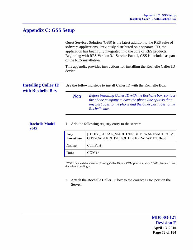
Appendix C: GSS SetupInstalling Caller ID with Rochelle Box
Appendix C: GSS Setup
Guest Services Solution (GSS) is the latest addition to the RES suite of software applications. Previously distributed on a separate CD, the application has been fully integrated into the core of RES products. Beginning with RES Version 3.1 Service Pack 1, GSS is included as part of the RES installation.
This appendix provides instructions for installing the Rochelle Caller ID device.
Installing Caller ID with Rochelle Box
Use the following steps to install Caller ID with the Rochelle Box.
Rochelle Model 2045
1. Add the following registry entry to the server:
*COM1 is the default setting. If using Caller ID on a COM port other than COM1, be sure to set the value accordingly.
2. Attach the Rochelle Caller ID box to the correct COM port on the Server.
Note Before installing Caller ID with the Rochelle box, contact the phone company to have the phone line split so that one part goes to the phone and the other part goes to the Rochelle box.
Key Location
[HKEY_LOCAL_MACHINE\SOFTWARE\MICROS\GSS\CALLERID\ROCHELLE\PARAMETERS]
Name ComPort
Data COM1*
MD0003-121Revision E
April 13, 2010Page 73 of 184

Appendix C: GSS SetupInstalling Caller ID with Rochelle Box
3. Start the MICROS Caller ID Service from the Windows Control Panel Services.
Rochelle Model 2050
1. Add the following registry entry to the server:
The device registry settings for the first device are added at the key location shown below. Default parameters are provide:
*COM1 is the default setting. If using Caller ID on a COM port other than COM1, be sure to set the value accordingly.
Note Visit www.rochelle.com for more information about installing your Caller ID device.
Key Location
[HKEY_LOCAL_MACHINE\SOFTWARE\MICROS\GSS\CALLERID\ROCHELLE]
Name NumDevices
Data 1
Key Location
[HKEY_LOCAL_MACHINE\SOFTWARE\MICROS\GSS\CALLERID\ROCHELLE\PARAMETERS]
Name ComPort
Data COM1*
Name ComParameters
Data Baud = 2400 Parity = N Data = 8 Stop = 1
Name InitString
Data AT_F0\r\nAT_R0=0\r\n
Name DeviceLines
Data 4
MD0003-121Revision EApril 13, 2010Page 74 of 184

Appendix C: GSS SetupInstalling Caller ID with Rochelle Box
The device registry settings for each additional device are added at \SOFTWARE\MICROS\GSS\CALLERID\ROCHELLE\PARAMETERS[#], where [#] refers to the device number. The table below provides the default parameters for sample Device 2:
2. Attach the Rochelle Caller ID box to the correct COM port on the Server.
3. Start the MICROS Caller ID Service from the Windows Control Panel Services.
Key Location
[HKEY_LOCAL_MACHINE\SOFTWARE\MICROS\GSS\CALLERID\ROCHELLE\PARAMETERS2]
Name ComPort
Data COM3
Name ComParameters
Data Baud = 2400 Parity = N Data = 8 Stop = 1
Name InitString
Data AT_F0\r\nAT_R0=0\r\n
Name DeviceLines
Data 4
Note Visit www.rochelle.com for more information about installing your Caller ID device.
MD0003-121Revision E
April 13, 2010Page 75 of 184

Appendix C: GSS SetupRunning Caller ID in Demo Mode
Running Caller ID in Demo Mode
Use the following steps to run Caller ID in Demo Mode:
1. Add the following registry entry to the server:
*COM1 is the default setting. If using Caller ID on a COM port other than COM!, be sure to set the value accordingly.
2. Attach a null model cable from COM1 to COM2 on the server.
3. Start the Rochelle Emulator.
4. Start the MICROS Caller ID Service from the Windows Control Panel Services.
Key Location
[HKEY_LOCAL_MACHINE\SOFTWARE\MICROS \GSS\CALLERID\ROCHELLE\PARAMETERS]
Name ComPort
Data COM1*
Note The Rochelle emulator can be found on the Guest Services Solution product page at www.micros.com.
MD0003-121Revision EApril 13, 2010Page 76 of 184
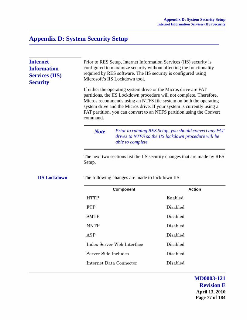
Appendix D: System Security SetupInternet Information Services (IIS) Security
Appendix D: System Security Setup
Internet Information Services (IIS) Security
Prior to RES Setup, Internet Information Services (IIS) security is configured to maximize security without affecting the functionality required by RES software. The IIS security is configured using Microsoft’s IIS Lockdown tool.
If either the operating system drive or the Micros drive are FAT partitions, the IIS Lockdown procedure will not complete. Therefore, Micros recommends using an NTFS file system on both the operating system drive and the Micros drive. If your system is currently using a FAT partition, you can convert to an NTFS partition using the Convert command.
The next two sections list the IIS security changes that are made by RES Setup.
IIS Lockdown The following changes are made to lockdown IIS:
Note Prior to running RES Setup, you should convert any FAT drives to NTFS so the IIS lockdown procedure will be able to complete.
Component Action
HTTP Enabled
FTP Disabled
SMTP Disabled
NNTP Disabled
ASP Disabled
Index Server Web Interface Disabled
Server Side Includes Disabled
Internet Data Connector Disabled
MD0003-121Revision E
April 13, 2010Page 77 of 184
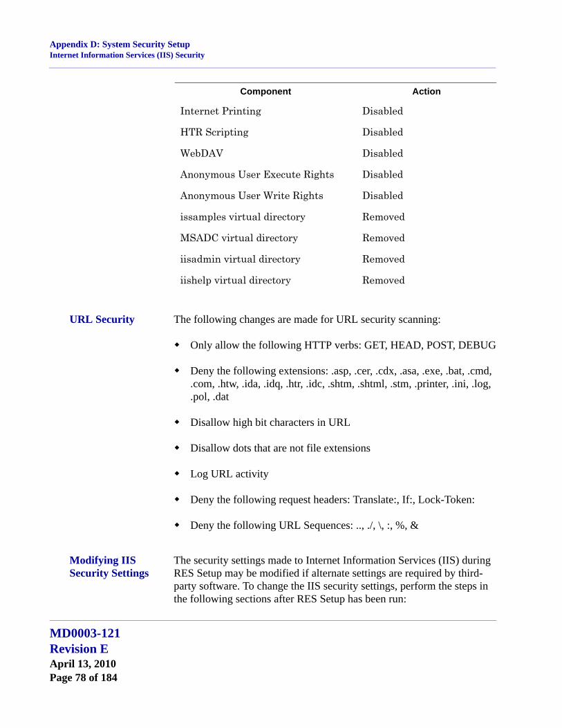
Appendix D: System Security SetupInternet Information Services (IIS) Security
URL Security The following changes are made for URL security scanning:
Only allow the following HTTP verbs: GET, HEAD, POST, DEBUG
Deny the following extensions: .asp, .cer, .cdx, .asa, .exe, .bat, .cmd, .com, .htw, .ida, .idq, .htr, .idc, .shtm, .shtml, .stm, .printer, .ini, .log, .pol, .dat
Disallow high bit characters in URL
Disallow dots that are not file extensions
Log URL activity
Deny the following request headers: Translate:, If:, Lock-Token:
Deny the following URL Sequences: .., ./, \, :, %, &
Modifying IIS Security Settings
The security settings made to Internet Information Services (IIS) during RES Setup may be modified if alternate settings are required by third-party software. To change the IIS security settings, perform the steps in the following sections after RES Setup has been run:
Internet Printing Disabled
HTR Scripting Disabled
WebDAV Disabled
Anonymous User Execute Rights Disabled
Anonymous User Write Rights Disabled
issamples virtual directory Removed
MSADC virtual directory Removed
iisadmin virtual directory Removed
iishelp virtual directory Removed
Component Action
MD0003-121Revision EApril 13, 2010Page 78 of 184
Appendix D: System Security SetupInternet Information Services (IIS) Security
Restore Security Settings1. Run iislockd.exe from the \MICROS\NetSetup\System32\inetsrv
directory.
2. Click Next.
3. Select Yes.
4. Click Next.
5. Click Finish.
The security settings are restored to their most recent previous state, which is either prior to running RES Setup or the last time iislockd.exe was run.
Modify the IIS Files1. Edit the [MICROSALT] section of the iislockd.ini file located in the
\MICROS\NetSetup\System32\inetsrv directory as required..
2. Edit the urlscan_micros_customer.ini files located in the \MICROS\NetSetup\System32\inetsrv directory as required..
Warning Do not modify the [MICROS] section of the iislockd.ini file.
Note Refer to the Iislockd.chm file located in the \MICROS\NetSetup\System32\inetsrv directory for information on modifying this file.
Warning Do not modify the urlscan_micros_default.ini file.
Note Refer to the UrlScan.doc file located in the \MICROS\NetSetup\System32\inetsrv directory for information on modifying this file.
MD0003-121Revision E
April 13, 2010Page 79 of 184
Appendix D: System Security SetupInternet Information Services (IIS) Security
Loading the Security Settings1. Run iislockd.exe from the \MICROS\NetSetup\System32\inetsrv
directory.
2. Select Agree on the Microsoft license agreement screen.
3. Select Customer Configurable Settings.
4. Click Next three times for processing to begin.
5. Click Next.
6. Click Finish.
Starting the Default Web SiteIt may be necessary to start the default web site once the security settings are loaded. To start the default web site:
1. Select Start Menu | Settings | Control Panel | Administrative Tools | Internet Services Manager.
2. If the default web site is stopped, right-click on the site and select Start.
Note To return to the default MICROS settings, select MICROS Default Settings.
Note If you are running a Windows Server product with more than one web site, use these steps to start the appropriate web sites. If there are multiple web sites, there may not be a “default web site”.
MD0003-121Revision EApril 13, 2010Page 80 of 184

Appendix D: System Security SetupFirewall Setup
Firewall Setup Firewalls should be enabled prior to installing RES 4.x on a Windows XP or 2003 Server. Setup will vary depending on the operating system used.
Windows XP with SP2 or higher
On the Win XP platform, firewalls are supported beginning with Service Pack 2. Follow these steps to enable the firewall:
1. From the Windows Start menu, select Settings | Control Panel | Windows Firewall to open the properties form.
2. On the General tab, select the On radio button and press OK to save. Exit the form.
3. Install RES.
Windows 2003 Server with SP1 or higher
On the Win 2003 platform, firewalls are supported beginning with Service Pack 1. Follow these steps to enable the firewall:
1. From the Windows Start menu, select Settings | Control Panel | Administrative Tools | Services.
2. Double-click the Windows Firewall/ICS service to open the properties form. The General tab will be displayed.
3. From the Startup-type drop-down list, set the service to Automatic.
4. Press the Start button to start the service and OK to save. Exit the form.
5. Install RES.
If the firewall is enabled after installation, the clients will not be able to communicate with the server and will continuously display prompts for Backup Server Mode (BSM) and Stand-alone Resiliency (SAR).
Once RES is installed, the problem can be corrected by running the batchfile %MicrosDrive%\Micros\common\Bin\ConfigureICF.bat. This will update the exceptions list that RES needs to successfully run with the firewall enabled.
MD0003-121Revision E
April 13, 2010Page 81 of 184

Appendix D: System Security SetupFirewall Setup
Exceptions RES 4.0 or higher allows the following exceptions to the Windows firewall:
MDSHttpService.exe (MICROS MDS Http Service)
DBEng9.exe (MICROS Database Engine
Cmbo.exe (MICROS Cash Management Back Office)
CM.exe (MICROS Cash Management Server)
Procedures.exe (MICROS Manager Procedures
OPS.exe (MICROS POS Operations)
MicrosDsk.exe (MICROS Desktop)
CALSrv.exe (MICROS CAL Service)
McrsCAL.exe (MICROS CAL Client)
DBSrv9.exe (Sybase Database Server)
ILDS.exe (International Liquor Dispensing Server)
KDSDisplay.exe (KDS Display Client)
KDSController.exe (Kitchen Display Server)
CIService.exe (Caller ID Server)
File and Print Sharing
MD0003-121Revision EApril 13, 2010Page 82 of 184

Appendix E: Frequently Asked Questions (FAQs)RES 4.x Issues
Appendix E: Frequently Asked Questions (FAQs)
This section provides answers to the most frequently asked questions about RES.
RES 4.x Issues 1. Why won’t the image display after I replace the res3700.bmp file in \micros\res\pos\etc folder?
The res3700.bmp has been moved to the \Bitmaps folder under MICROS. RES Setup automatically moves this file from its old location to the folder. If you wish to place your own res3700.bmp on the system, you must copy it to the appropriate folder location on each client, as indicated below:
Win32 Clients — \MICROS\RES\POS\Bitmaps.
WS4 Clients — \MICROS\Bitmaps:
To replace the file on the WS4:
1. Copy the res3700.bmp to the following folder on the RES Server: \MICROS\RES\CAL\WS4\Files\CF\MICROS\ Bitmaps
2. Wait up to 30 seconds for the file to transfer to the WS4 Client.
3. Reboot the WS4 Client to load the image for POS Operations.
Note A single .bmp file may be used on all three platforms. However, you may want to create a separate file for the Mobile MICROS due to its smaller screen size.
MD0003-121Revision E
April 13, 2010Page 83 of 184

Appendix E: Frequently Asked Questions (FAQs)RES 4.x Issues
WS4 LX Clients — \MICROS\Bitmaps:
To replace the file on the WS4 LX:
1. Copy the res3700.bmp to the following folder on the RES Server: \MICROS\RES\CAL\WS4LX\Files\CF\MICROS\ Bitmaps
2. Wait up to 30 seconds for the file to transfer to the WS4 LX Client.
3. Reboot the WS4 LX Client to load the image for POS Operations.
WS5 Clients — \MICROS\Bitmaps:
To replace the file on the WS5:
1. Copy the res3700.bmp to the following folder on the RES Server: \MICROS\RES\CAL\WS5\Files\CF\MICROS\ Bitmaps
2. Wait up to 30 seconds for the file to transfer to the WS5 Client.
3. Reboot the WS5 Client to load the image for POS Operations.
Mobile MICROS — \MICROS\Bitmaps.
To replace the file on the Mobile MICROS client:
1. Copy the res3700.bmp to the following folder on the RES Server: \MICROS\RES\CAL\HHT\MICROS\Bitmaps
2. Wait up to 30 seconds for the file to transfer to the Mobile MICROS Client.
3. Reboot the Mobile MICROS Client to load the image for POS Operations.
MD0003-121Revision EApril 13, 2010Page 84 of 184

Appendix E: Frequently Asked Questions (FAQs)RES 4.x Issues
PPC Clients — \MICROS\Bitmaps:
To replace the file on the PPC:
1. Copy the res3700.bmp to the following folder on the RES Server: \MICROS\CAL\PPC\Files\MICROS\ Bitmaps
2. Wait up to 30 seconds for the file to transfer to the PPC Client.
3. Reboot the PPC Client to load the image for POS Operations.
PPC70 Clients — \MICROS\Bitmaps:
To replace the file on the PPC70:
1. Copy the res3700.bmp to the following folder on the RES Server: \MICROS\CAL\PPC70\Files\MICROS\ Bitmaps
2. Wait up to 30 seconds for the file to transfer to the PPC70 Client.
3. Reboot the PPC70 Client to load the image for POS Operations.
2. Why are all client nodes listed in the POS Configurator (Devices | Network Nodes) displayed in the MICROS Control Panel even when they are not currently connected to the system?
With this release, MICROS Control Panel allows the user to specify whether all client nodes or just connected client nodes will be displayed. Previously (Version 3.1 and lower), only connected client nodes were shown. This remains the default behavior.
Note Bitmaps used for POS touchscreen keys should also be placed in the \Bitmaps folder.
MD0003-121Revision E
April 13, 2010Page 85 of 184

Appendix E: Frequently Asked Questions (FAQs)RES 4.x Issues
To display all clients:
1. From the Windows Start Menu, select Programs | MICROS Applications | MICROS Control Panel.
2. Go to the menu bar and select View | Show All Clients. The system tree is modified to display all clients.
MD0003-121Revision EApril 13, 2010Page 86 of 184

Appendix E: Frequently Asked Questions (FAQs)RES 4.x Issues
3. After changing the computer name or IP address of the Server, why can’t I start POS Operations on any of my clients?
Changes made to the Server identity are not automatically propagated out to the clients. To send these changes to the clients:
1. From the Windows Start Menu, select Programs | MICROS Applications | MICROS Control Panel.
2. Highlight the SQL Database Server node.
3. Go to the Status tab and click the Reload button.
Within a few minutes, the clients should be operational.
4. Is the host file still important to the system?
Yes, the host file is still used by the RES System and must be accurate. The RES System also uses a file called MDSHosts.xml. This file is automatically generated by the system and should not be manually copied or edited by the user. The location of the file depends on the platform, as indicated below:
Server — \MICROS\Common\etc
Win32 Clients — \MICROS\Common\etc
WS4, WS4 LX, WS5 Clients — \CF\MICROS\etc
Mobile MICROS — \MICROS\etc
RDC Clients — \FS2\MICROS\etc
Note For troubleshooting purposes, this file may be read only. Do not edit this file in any way.
MD0003-121Revision E
April 13, 2010Page 87 of 184

Appendix E: Frequently Asked Questions (FAQs)Client Issues
This file is generated by the system and is based on information from the MICROS database. The following POS Configurator forms need to have accurate client information in order for the file to be correct:
Devices | Network Node
Devices | Devices
Devices | User Workstations
System | Restaurant
Client Issues 1. Can I save the Compact Flash on a malfunctioning MICROS 3700 WS4?
Yes. If you have a WS4 Client that has gone bad, you simply remove the Compact Flash from that unit and install it into a good WS4.
2. Can I move a WS4 from one system to another?
Yes. To do this, follow these steps to remove the MICROS folder from the Compact Flash of the WS4 before installing a unit into a RES System:
1. On the WS4, open the Windows Explorer and navigate to \CF.
2. Delete the \MICROS subfolder at this location.
3. Power up the WS4 Client and establish a network connection to the system.
Note For information and instructions on removing/installing the Compact Flash, please refer to the Workstation 4 Setup Guide, available on the MICROS website under Products | Hardware Solutions | Documentation.
MD0003-121Revision EApril 13, 2010Page 88 of 184

Appendix E: Frequently Asked Questions (FAQs)Client Issues
4. Reconfigure CAL as follows:Select Start | Programs | CAL | Reconfigure CAL.
Select the RES Server to which this WS4 will be connected. (Do not select the DHCP option.)
Select a name for this WS4 Client from the list of available nodes.
Save the configuration. CAL will update the unit with the system application software.
3. How do I map a drive to a WS4 client?
You don’t. The WS4 does not allow files to be transferred to it using traditional Windows methods. Instead, files are transferred to the unit via the Client Application Loader (CAL). For information on setting up CAL packages and files, refer to Client Application Loader (CAL) File Specification (MD0003.061), available as CAL.pdf in the \Support\sdk folder on the RES 4.x CD.
On the other hand, the system Server and its hard-drive (Win32) clients may be accessed from the WS4 using a method similar to Windows mapping. To do this:
1. From the WS4, open the Windows Explorer.
2. In the location box, type the UNC path of the PC to be accessed.
For example, to access the c:\micros\res\pos share on a server with a computer name of “RESServer 5,” enter \\RESServer5\micros\res\pos.
Once the appropriate share has been accessed, you may perform the required Windows operation.
MD0003-121Revision E
April 13, 2010Page 89 of 184
Appendix E: Frequently Asked Questions (FAQs)Client Issues
4. How do I set up my custom icons to work on a Mobile MICROS and WS4 client?
The customicons.dll created for previous versions of RES will work only on hard-drive clients. Additional customicons.dll files were created for Mobile MICROS and WS4 devices. As before, you will need to load your own icons into these files using an Icon Editor.
All customicons.dll files are available in the Support\CustomIcons folder on the RES 4.x CD and must be manually copied to the folder location for each client type:
Win32 Clients — \MICROS\RES\POS\Bin
WS4 Clients — \MICROS\Bin
To copy the file to the WS4:
1. Create a \MICROS\RES\CAL\WS4\Files\CF\MICROS\Bin folder on the RES Server:
2. Copy the WS4 customicons.dll to this folder.
3. Wait up to 30 seconds for the file to transfer to the WS4 Client.
Mobile MICROS — \MICROS\Bin
To copy the file to the Mobile MICROS client:
1. Create a \MICROS\RES\CAL\HHT\MICROS\Bin folder on the RES Server:
2. Copy the Mobile MICROS customicons.dll to this folder.
3. Wait up to 30 seconds for the file to transfer to the Mobile MICROS Client.
Note You will need to reboot the clients in order for the images to take effect.
MD0003-121Revision EApril 13, 2010Page 90 of 184
Appendix E: Frequently Asked Questions (FAQs)Client Issues
5. How do I copy my OPSDisplayUser.cfg to all clients?
A single OPSDisplayUser.cfg file may be used on all three platforms. However, because it is not included in RES Setup, the file will not automatically copy during the installation. Instead, it must be manually copied to the following folder location for each client type:
Win32 Clients — \MICROS\RES\POS\etc
WS4 Clients — \MICROS\etc
To transfer the file to the WS4:
1. Copy the OPSDisplayuser.cfg file to the \MICROS\RES\CAL\ WS4\Files\CF\MICROS\etc folder on the RES Server.
2. Wait up to 30 seconds for the file to transfer to the WS4 Client.
3. Reboot the WS4 Client to load the settings for POS Operations.
WS4 LX Clients — \MICROS\etc
To transfer the file to the WS4 LX:
1. Copy the OPSDisplayuser.cfg file to the \MICROS\RES\CAL\ WS4LX\Files\CF\MICROS\etc folder on the RES Server.
2. Wait up to 30 seconds for the file to transfer to the WS4 LX Client.
3. Reboot the WS4 LX Client to load the settings for POS Operations.
MD0003-121Revision E
April 13, 2010Page 91 of 184

Appendix E: Frequently Asked Questions (FAQs)Client Issues
WS5 Clients — \MICROS\etc
To transfer the file to the WS5:
1. Copy the OPSDisplayuser.cfg file to the \MICROS\RES\CAL\ WS5\Files\CF\MICROS\etc folder on the RES Server.
2. Wait up to 30 seconds for the file to transfer to the WS5 Client.
3. Reboot the WS5 Client to load the settings for POS Operations.
Mobile MICROS — \MICROS\etc
To transfer the file to the Mobile MICROS:
1. Copy the OPSDisplayuser.cfg file to the \MICROS\RES\CAL\ HHT\MICROS\etc folder on the RES Server.
2. Wait up to 30 seconds for the file to transfer to the Mobile MICROS Client.
3. Reboot the Mobile MICROS Client to load the settings for POS Operations.
6. How do I copy custom scripts to all clients?
Scripts are custom files, created by the installer to do a variety of tasks. They are not included during installation, but must be manually copied to the appropriate directory.
Note Because the WS4 and Mobile MICROS platforms are based on Windows CE, existing Win32 scripts may not work on those platforms. Be aware that compiled files may need to be recompiled in a development environment that supports this type of Operating System.
MD0003-121Revision EApril 13, 2010Page 92 of 184

Appendix E: Frequently Asked Questions (FAQs)Client Issues
Although scripts can reside anywhere on the system, MICROS recommends storing them together in the Scripts folder. The location of this folder will vary, depending on the client type:
Win32 Clients — \MICROS\RES\POS\Scripts
WS4 Clients — \MICROS\Scripts
To add scripts to the WS4:
1. Copy file(s) to the \MICROS\RES\CAL\WS4\Files\CF\ MICROS\Scripts folder on the RES Server.
2. Wait up to 30 seconds for the file(s) to transfer to the WS4 Client.
WS4 LX Clients — \MICROS\Scripts
To add scripts to the WS4 LX:
1. Copy file(s) to the \MICROS\RES\CAL\WS4LX\Files\CF\ MICROS\Scripts folder on the RES Server.
2. Wait up to 30 seconds for the file(s) to transfer to the WS4 LX Client.
WS5 Clients — \MICROS\Scripts
To add scripts to the WS5:
1. Copy file(s) to the \MICROS\RES\CAL\WS5\Files\CF\ MICROS\Scripts folder on the RES Server.
2. Wait up to 30 seconds for the file(s) to transfer to the WS5 Client.
MD0003-121Revision E
April 13, 2010Page 93 of 184
Appendix E: Frequently Asked Questions (FAQs)Client Issues
Mobile MICROS — \MICROS\Scripts
To add scripts to the Mobile MICROS:
1. Copy file(s) to the \MICROS\RES\CAL\ HHT\MICROS\Scripts folder on the RES Server.
2. Wait up to 30 seconds for the file(s) to transfer to the Mobile MICROS Client.
7. How do I copy SIM scripts to all clients?
A single SIM script (pmsxxx.isl) may be used on all three platforms. This file is not included during installation, but must be manually copied to the appropriate client directory.
Win32 Clients — \MICROS\RES\POS\etc
WS4 Clients — \MICROS\etc
To add SIM scripts to the WS4:
1. Copy the pmsxxx.isl file to the \MICROS\RES\CAL\WS4\ Files\CF\MICROS\etc folder on the RES Server.
2. Wait up to 30 seconds for the file to transfer to the WS4 Client.
Note Because the WS4 and Mobile MICROS platforms are based on Windows CE, existing Win32 scripts may not work on those platforms. For more information, refer to the RES 3.2 Read Me First (MD0003-057).
MD0003-121Revision EApril 13, 2010Page 94 of 184
Appendix E: Frequently Asked Questions (FAQs)Client Issues
WS4 LX Clients — \MICROS\etc
To add SIM scripts to the WS4 LX:
1. Copy the pmsxxx.isl file to the \MICROS\RES\CAL\WS4LX\ Files\CF\MICROS\etc folder on the RES Server.
2. Wait up to 30 seconds for the file to transfer to the WS4 LX Client.
WS5 Clients — \MICROS\etc
To add SIM scripts to the WS5:
1. Copy the pmsxxx.isl file to the \MICROS\RES\CAL\WS5\ Files\CF\MICROS\etc folder on the RES Server.
2. Wait up to 30 seconds for the file to transfer to the WS5 Client.
Mobile MICROS — \MICROS\etc
To add SIM scripts to the Mobile MICROS:
1. Copy the pmsxxx.isl file to the \MICROS\RES\CAL\ HHT\MICROS\etc folder on the RES Server.
2. Wait up to 30 seconds for the file to transfer to the Mobile MICROS Client.
8. How do I open a file on a WS4, WS4 LX, WS5, or RDC Client?
Files can be opened on a WS4, WS4 LX, WS5, or RDC Client as follows:
Using WordPad:
From the Windows Start Menu, select Programs | Microsoft WordPad to start the application.
From the menu bar, select File | Open to launch the dialog box.
MD0003-121Revision E
April 13, 2010Page 95 of 184
Appendix E: Frequently Asked Questions (FAQs)Client Issues
Browse to the appropriate file and select. (You may need to change the File Type to All Documents to locate the desired file.)
Double-click to open the file.
Opening a file directly:
Locate the required file in the Window Explorer.
Rename the file, giving it a .txt or .doc extension.
Double-click to open the file.
9. Where can I find MICROS Confidence Test on a WS4, WS4 LX, or WS5 Client?
This application can be launched from the Windows Start Menu by selecting Programs | MICROS Applications | Confidence Test.
If a shortcut for the MICROS Confidence test is not available, you can always access the program via Explorer using the following steps:
From the Windows Start Menu, select Programs | Windows Explorer.
Open \CF\MICROS\bin.
Touch microscfdtest.exe twice.
Note The WS4 comes with a built-in diagnostic utility for all hardware components. This utility may also be used. To access it:
From the Desktop, touch the My Computer icon twice.
Touch the DOC icon twice.
Touch the Utilities folder twice.
Touch the DiagUtility icon twice to start the WS4 diagnostic utility.
MD0003-121Revision EApril 13, 2010Page 96 of 184
Appendix E: Frequently Asked Questions (FAQs)Client Issues
10. How do I open the Windows Registry on a WS4, WS4 LX, or WS5 Client?
The registry on a WS4, WS4 LX, and WS5 is similar to a Win32 client registry. MICROS does not recommend editing the registry directly. However, should it be necessary, the following steps should be taken:
From the Windows Start menu, select Programs | Windows Explorer.
Open \DOC\Utilities.
Touch the regeditWS4.exe twice to start the WS4 registry editor.
11. How do I open the Windows Registry on a RDC Client?
The registry on a RDC is similar to a Win32 client registry. MICROS does not recommend editing the registry directly. However, should it be necessary, the following steps should be taken:
From the Windows Start menu, select Programs | Windows Explorer.
Open \FS\Utilities.
Touch the regeditCE.exe twice to start the RDC registry editor.
12. How do I start POS Operations on a WS4, WS4 LX, or WS5 Client?
If the Client is up, POS Operations should be running already. That is the default start position for this workstation. If it is not, you may start POS Operations by going to the Windows Start Menu and selecting Programs | MICROS Applications | Start RES.
Note Mobile MICROS Clients do not permit direct access to the registry.
MD0003-121Revision E
April 13, 2010Page 97 of 184
Appendix E: Frequently Asked Questions (FAQs)Client Issues
If a shortcut is not available, you can always access the program via Explorer using the following steps:
From the Windows Start Menu, select Programs | Windows Explorer.
Open \CF\MICROS\bin.
Touch AppStarter.exe twice.
13. Why does POS Operations say “System Closed” on a Client?
Although POS Operations should always be running on the clients, that does not guarantee the units will be operational (i.e., able to ring transactions).
In RES 4.0 or higher, clients are not individually controlled by the MICROS Control Panel. You cannot start and stop POS Operations on these devices.
All clients are considered unmanaged clients — they take on the state of the RES Server. Therefore, if the Server is set to Back of House in the MICROS Control Panel, then all unmanaged clients will display a “System Closed” screen.
To ring transactions on unmanaged clients, the MICROS Control Panel must set the entire RES System (i.e., the Restaurant) to Front of House.
14. How do I bring up the CE Task Manager on a WS4, WS4 LX, WS5, or RDC Client?
To start Task Manager on a WS4 Client, hold down the [Alt] key and press the [Tab] key on the keyboard.
MD0003-121Revision EApril 13, 2010Page 98 of 184
Appendix E: Frequently Asked Questions (FAQs)Client Issues
15. How do I access other applications while POS Operations is running on a WS4, WS4 LX, or WS5 Client?
The CE Operating System does not provide a mechanism for minimizing POS Operations. You can still program a Minimize function key on a touchscreen, but be aware that when the key is pressed, it will bring up the Windows CE Start Bar. From here, you can access other applications, as necessary.
If a keyboard is attached to the Client, the Windows CE Start Bar may be accessed by holding down [Ctrl] and pressing the [Esc] key.
16. How do I shutdown POS Operations on a WS4, WS4 LX, or WS5 Client?
Although MICROS does not recommend shutting down POS Operations, we recognize that sometimes this is necessary for troubleshooting purposes.
To shutdown POS Operations, attach a keyboard to the Client and do the following:
Bring up the Windows CE Start Bar by pressing the [Ctrl]-[Esc] key combination simultaneously.
Hold down the [Alt] key and touch the POS Operations application that appears in the Task Bar. A Close option will display at the bottom of the screen.
Press Close to shutdown POS Operations.
MD0003-121Revision E
April 13, 2010Page 99 of 184

Appendix E: Frequently Asked Questions (FAQs)Client Issues
17. How do I turn off my WS4, WS4 LX, or WS5 Client?
The power switch is located on the front right of the unit, on the underside of the display screen. It is a small circular switch that protrudes very little and can be easily missed.
To turn off the unit, you must hold the power switch for at least five seconds. Make sure that the Operator LED changes from a solid green or blue to OFF. This is critical. Failure to properly turn off the power will place the unit in Suspend Mode, not OFF. For more information about the power switch and it’s different states, refer to the Workstation 4 Setup Guide, available from the MICROS Website under Products | Hardware | Documentation.
18. How do I create a screen capture on a Mobile MICROS HHT or a WS4, WS4 LX, or WS5 Client?
Microsoft provides a utility called “Remote Display Control” which may be used through ActiveSync® to capture HHT screens and save them as bitmap files.
Currently, there are no tools available to capture screens on a WS4, WS4 LX, or WS5.
19. Can I load other applications on a WS4, WS4 LX, or WS5 Client?
The WS4, WS4 LX, and WS5 are capable of running any CE-compatible application. However, the WS4, WS4 LX, and WS5 are each intended to be a POS appliance that allows the RES user to run POS Operations and Manager Procedures. By running other applications on the WS4, WS4 LX, or WS5, you assume the responsibility for installation and testing on this platform.
MD0003-121Revision EApril 13, 2010Page 100 of 184

Appendix E: Frequently Asked Questions (FAQs)Client Issues
The WS4, WS4 LX, and WS5 have a built-in Client Application Loader (CAL). Additional information can be found in the Workstation 4 Setup Guide and in the Client Application Loader (CAL) File Specification (MD0003-061), available as CAL.pdf in the \Support\CAL folder available on the RES 4.x CD.
20. Do I need to translate POS Operations text for each client platform?
No. You can create one set of POS Operations’ translation files and copy them to all three platforms.
21. Why are my fonts different sizes since I upgraded?
Please refer to the document “Editing OPSDisplayUserConfig File,” located on the RES 4.x CD under \Support\OPSDisplayUser\OPSDisplayUserCfg.pdf.
22. Is there a way to set the number of lines displayed in the database tables?
Yes. By default, when viewing any of the database tables through the Interactive SQL (DBISQL), there is a MICROS-imposed limit of 500 records. To change this:
1. Open ISQL by selecting Start | MICROS Applications | Utilities | Database | Sybase Adaptive Server Anywhere | Interactive SQL.
2. From the menu bar, select Tools | Options and click on the Results icon.
3. Change the Maximum number of rows to display to the desired value.
MD0003-121Revision E
April 13, 2010Page 101 of 184
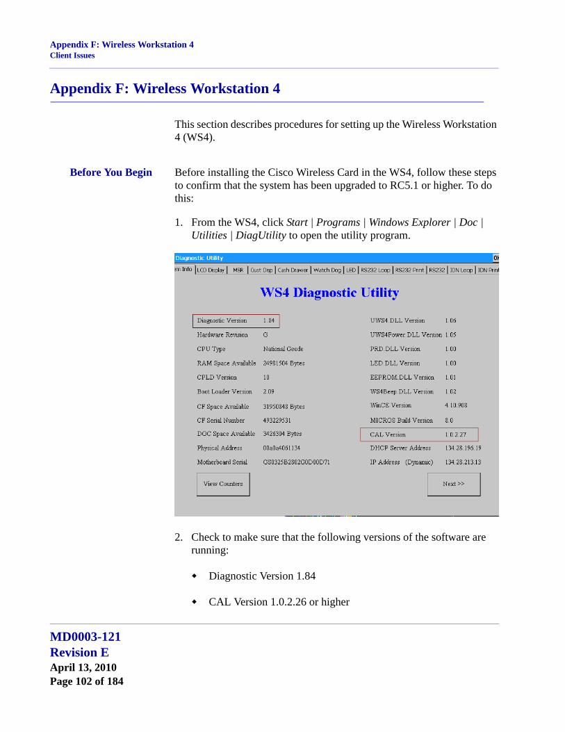
Appendix F: Wireless Workstation 4Client Issues
Appendix F: Wireless Workstation 4
This section describes procedures for setting up the Wireless Workstation 4 (WS4).
Before You Begin Before installing the Cisco Wireless Card in the WS4, follow these steps to confirm that the system has been upgraded to RC5.1 or higher. To do this:
1. From the WS4, click Start | Programs | Windows Explorer | Doc | Utilities | DiagUtility to open the utility program.
2. Check to make sure that the following versions of the software are running:
Diagnostic Version 1.84
CAL Version 1.0.2.26 or higher
MD0003-121Revision EApril 13, 2010Page 102 of 184

Appendix F: Wireless Workstation 4Client Issues
If these versions are not installed on the workstation(s), you will need to upgrade the system through the Client Application Loader (CAL), using a hard-wired network cable. This must be done before configuring the wireless network card.
EncryptionThe wireless Cisco card does not support 128-bit encryption. If you are using 128-bit encryption on your wireless access point, you will need to downgrade it to 40-bit encryption.
Configuring the Workstation
Once the workstation is running the correct versions of the software, follow these steps to configure for wireless communication:
1. In the MICROS Control Panel, set the Restaurant level to Off or Database.
2. Power off the WS4.
3. Disconnect any LAN cables.
4. Insert the Cisco wireless card into the card slot on the bottom of the WS4.
5. Power on the WS4.
6. After the system restarts (the first 1-2 seconds), press [Ctrl]-[Shift]-[End] to exit CAL.
7. Configure the wireless card:
From the Windows Start menu, click Settings | Control Panel | Network and Dial-up Connections.
Select CISCO1. A dialog window is displayed.
On the IP Address tab, select one of the radio buttons to either manually enter an IP Address or use DHCP to assign one automatically.
MD0003-121Revision E
April 13, 2010Page 103 of 184
Appendix F: Wireless Workstation 4Client Issues
Skip the Name Servers tab.
Go to the Wireless Networks tab).
Select an access point from the list of Available Networks and click the Configure button to define encryption that will allow the workstation and access point to communicate.
An example of 40-bit encryption would be:
1. Enable only the Data encryption (WEP enabled) option.
2. Disable all other options.
3. Click Modify WEB KEY.
4. Input the network key (e.g., 1011121314). The access key should be the same value/number you selected when you configured your wireless access point for encryption. If you are using a Symbol device, you have the ability to insert your own values or select one of four predefined values.
5. In the Key Format box, choose Hexadecimal digits.
6. Select a Key Length of 40-bit (10 digits).
7. The Key Index can remain at 0.
8. Click OK to exit.
9. Click OK again.
10. Verify that your selected network is in the Preferred networks list. If not, highlight it and click the Add button.
MD0003-121Revision EApril 13, 2010Page 104 of 184

Appendix F: Wireless Workstation 4Client Issues
Other Security ConsiderationsWhile configuring the CISCO card, users may define the Network to Access. This is done through the Windows Start Menu by selecting Settings | Control Panel | Cisco1 | Wireless Networks and clicking the Advanced button.
The following options are presented:
1. Any available Network (access point preferred).
2. Access point (Infrastructure) networks only.
3. Computer-to-Computer (Ad hoc) networks only.
For greater security, MICROS recommends using option 2, allowing communications with the defined access point only.
8. Exit all forms.
9. From the ICON tray (bottom right corner of the task bar), double-click on the Cisco1 network icon. The icon looks like 2 computer screens.
10. Go to the IP Information tab and confirm the information.
11. Go to the Wireless Information tab. Confirm the connection to the access point and signal strength.
12. Reboot the WS4.
Once the unit comes back up, the error message “Network Cable is not connected. Please reconnect.” may be displayed. Click OK to continue. This message is triggered by a timeout condition and does not affect operation. It will be addressed in the next version of CAL.
Be advised that the message may display every time the workstation is rebooted. In addition, the system may ask if you want to disable CAL. If this occurs, select No.
MD0003-121Revision E
April 13, 2010Page 105 of 184
Appendix F: Wireless Workstation 4Client Issues
At this point, the system should be on the network and CAL should be looking for updates. If not, retrace your steps and try again.
Known Issues The following issues have been noted while configuring the Wireless Workstation 4:
1. Location and antenna positions are very fragile. Moving the antenna six inches can cause the WS4 to lose its connection and create a system-closed message until the signal is reacquired. When this happens, the WS4 should go to SAR Mode, provided that the feature is enabled.
2. Side-by-side WS4 units displayed different characteristics in their ability to get a signal, and in the degree of signal strength going to the same access point.
Note If you are changing the IP Address or the Name of either the Client or Server, you will need to configure the POS Configurator accordingly.
In addition, you will need to point the workstation to the Server by going to the Windows Start Menu and selecting Programs | Reconfigure CAL.
MD0003-121Revision EApril 13, 2010Page 106 of 184
Appendix G: SwitchTo.exeDescription
Appendix G: SwitchTo.exe
Description SwitchTo.exe is a Windows application that allows users to change the system’s focus (i.e., the active, foreground window) from one application to another using a command-line prompt.
Platforms Win32, CE-WS4
File Location: %RESROOTDIR%\Bin
Usage SwitchTo.exe is a command line application with 4 possible arguments:
-w WindowTitleThe -w switch tells the application to bring the window with the specified windows title to the foreground.
ExampleC:\MICROS\res\pos\bin>SwitchTo.exe -w 3700 POS Operations(Brings POS Operations to the foreground)
-c Class NameThe -c switch tells the application to bring the window with the specified windows class to the foreground.
ExampleC:\MICROS\res\pos\bin>SwitchTo.exe -c 3700OPSAPP
Note Using the Switchto.exe command without a command line parameter will display a short message box describing the available switches.
MD0003-121Revision E
April 13, 2010Page 107 of 184
Appendix G: SwitchTo.exeDescription
-s StartCommandThe -s command is to start an application if the window with the windows title or class name cannot be found.
ExampleC:\MICROS\res\pos\bin>SwitchTo.exe -w 3700 POS Operations -s Ops.exe(Starts OPS.exe if the Windows title cannot be found.)
Common NameThe common name allows windows that have different class names and Windows titles across platforms to be unified under a single, logical name. At this time, the only common name supported by the application is KDS.
ExampleC:\MICROS\res\pos\bin>SwitchTo.exe KDS
Configuring a Logical Name
Optional logical names can be added using the Windows registry. The optional logical names only operate on the windows title.
To add another logical name to the registry:
1. Make sure that following Key has been added:
HKEY_LOCAL_MACHINE\SOFTWARE\MICROS\Common\SwitchTo
2. Add a String Value to this registry key and enter the logical name as the string value identifier. Add the desired window title as the actual string value.
MD0003-121Revision EApril 13, 2010Page 108 of 184
Appendix G: SwitchTo.exeDescription
ExampleString Name: OPS
String Value: 3700 POS Operations
Sample Command: C:\MICROS\res\pos\bin>SwitchTo.exe OPS (changes focus to POS Operations)
MD0003-121Revision E
April 13, 2010Page 109 of 184
Appendix H: Order Confirmation Board (OCB)Installation
Appendix H: Order Confirmation Board (OCB)
This section contains instructions for installing, configuring, and using the 3700 POS Interface to the Texas Digital AccuView Order Confirmation Board (OCB), the Texas Digital Wenview OCB, and the MICROS OCB.
The OCB Interface supports output from the following POS Clients to the OCB device:
RES Server
Win32 Client
WS4 Client
WS4 LX Client
WS5 Client
*****************************IMPORTANT*******************************
Installing RES 4.8 will overwrite the existing Scripts\OCBserver.ini file. This new file will not have any default settings. Therefore, it is crucial that you Save a copy of your existing Scripts\OCBServer.ini Prior to running the 4.8 patch.
***************************************************************************
Installation In RES 4.x, OCB files are installed with RES Setup. Some editing, renaming and copying of the appropriate files is necessary to configure the system for use.
Procedures Follow these steps to configure the OCB Interface software:
1. Configure the files on the RES Server. After RES Setup has been run, all files are located in the %micros%\micros\res\pos\scripts folder.
MD0003-121Revision EApril 13, 2010Page 110 of 184

Appendix H: Order Confirmation Board (OCB)Installation
Confirm that the folders listed below exist on your server. If not, create them.
• OCBClient.isl Rename and copy to the following folders:• %microsdrive%\micros\res\cal\win32\files\micros\res\
pos\etc
• %microsdrive% \micros\res\cal\ws4\files\cf\micros\etc
• %microsdrive% \micros\res\cal\ws4LX\files\cf\micros\etc
• %microsdrive% \micros\res\cal\ws5\files\cf\micros\etc
• OCBClient.ini Copy to the following folders:• %microsdrive%\micros\res\cal\win32\files\micros\res\
pos\scripts
• %microsdrive%\micros\res\cal\ws4\files\cf\micros\scripts • %microsdrive%\micros\res\cal\ws4LX\files\cf\micros\scripts • %microsdrive%\micros\res\cal\ws5\files\cf\micros\scripts
2. Register the OCB Service on the Server. To do this select Run from the Windows Start menu. When the dialog box opens, enter the following text:
“%microsdrive%\micros\res\pos\scripts\OCBServer.exe” /servicePress OK.
This will install the service and configure it to automatically start when the Server is booted up.
Note The OCBClient.isl file must be renamed to match the Interface Configuration.
Note The installation of the client files to the CAL folder structure is all that is needed to install the OCB Interface software on a client. Once the files have been downloaded to the client, they may be deleted from the server and edited at the client level. This optional procedure allows you to create a unique configuration at any of the clients.
MD0003-121Revision E
April 13, 2010Page 111 of 184
Appendix H: Order Confirmation Board (OCB)Installation
3. Confirm that the Service has been properly installed. To do this:
From the Windows Start menu, select Settings | Control Panel | Administrative Tools | Services.
Confirm that there is an entry in the Service list for MICROS OCB Server and that its Startup Type is set to Automatic.
Highlight the entry and click the Start Service button. (This will be done automatically on subsequent reboots of the Server.)
MD0003-121Revision EApril 13, 2010Page 112 of 184

Appendix H: Order Confirmation Board (OCB)Configuration
Confirm that the service starts up without error. If an error is displayed, the cause is most likely a problem with the OCBServer.ini file. Among the likely errors messages are:
The data is Invalid — The OCBServer.ini file contains an invalid configuration.
The system cannot find the file specified — The OCBServer.ini file is missing or in the wrong location.
4. Add OCB Server to the Firewall Exception List. The ConfigureICF.bat file will be run automatically as part of installing the patch.
Configuration
Configuring the OCBServer.ini File
Most configuration is done at the Server in the OCBServer.ini file. This file defines the OCB devices attached to the system and the device-specific settings for each.
With the release of RES v. 4.8, a new MICROS OCB has been introduced that uses a new file (OCB.ini) located on the OCB. With this additional file, only some of the settings in the OCBServer.ini file are used, including [OCB1 Device], [OCB2 Device], [OCB1 Display Options], and [OCB2 Display Options]. For more information on the OCB.ini file, see “Configuring the MICROS OCB Device” on page 121.
Note After running RES Setup, the ConfigureICF.bat file can be found in the %microsdrive%\micros\common\bin folder.
MD0003-121Revision E
April 13, 2010Page 113 of 184
Appendix H: Order Confirmation Board (OCB)Configuration
Server Setup for the OCBServer.ini FileEach OCB device entry contains the following set of configuration items:
[Device] — Defines the device type and communication parameters.
DeviceType 0 = None1 = Texas Digital AccuVIEW2 = Texas Digital WenVIEW3 = Texas Digital AccuVIEW CE4 = Everbrite SNS OCS5 = MICROS OCB
ConnectType 1 = COM Port2 = TCP/IP [Currently supported for MICROS OCB only]
ComPort 1 = COM12 = COM2...etc.
BaudRate 1 = 12002 = 96003 = 19200 (Suggested Baud Rate for AccuVIEW OCB devices) 4 = 38400 5 = 576006 = 115200
NOTE: If the site encounters display issues set the baud rate to 19200 (3 in the OCBServer.ini file).
IpAddress IP Address [ipaddr:port] of the OCB device [MICROS OCB only]NOTE: The IP address is the IP address of the OCB device and the port value is found in the OCB.ini file, listed as the Listen Port value.
MD0003-121Revision EApril 13, 2010Page 114 of 184
Appendix H: Order Confirmation Board (OCB)Configuration
[Labels] — Defines the labels for various display elements.
TotalLabel Label displayed at the bottom of the OCB display immediately before the total due value.
TaxLabel Label displayed at the bottom of the OCB display immediately before the tax value.
TotalScreenLine1
Line 1 of the text displayed on the total screen. The total screen is displayed after an order has been completed and the associated check on the POS has been service totaled or final tendered.
TotalScreenLine2
Line 2 of the text displayed on the total screen.
[Default Message] — Defines the default message displayed on WenVIEW OCB devices.
This text is displayed whenever the OCB is idle and not taking an order.
Line1,Line2,...
Defines each line of the default Message. Can add or delete lines as necessary (Line3, Line4, etc.).
[Scroll Text] — Defines the set of messages scrolled at the bottom of the OCB display.
AccuVIEW devices can display an unlimited number of scroll messages.WenVIEW devices can display only 1 scroll message.
ScrollText1,ScrollText2,...
Defines the text of each scrolling message. Can add/delete scroll messages as necessary (ScrollText3, ScrollText4, etc.).
MD0003-121Revision E
April 13, 2010Page 115 of 184
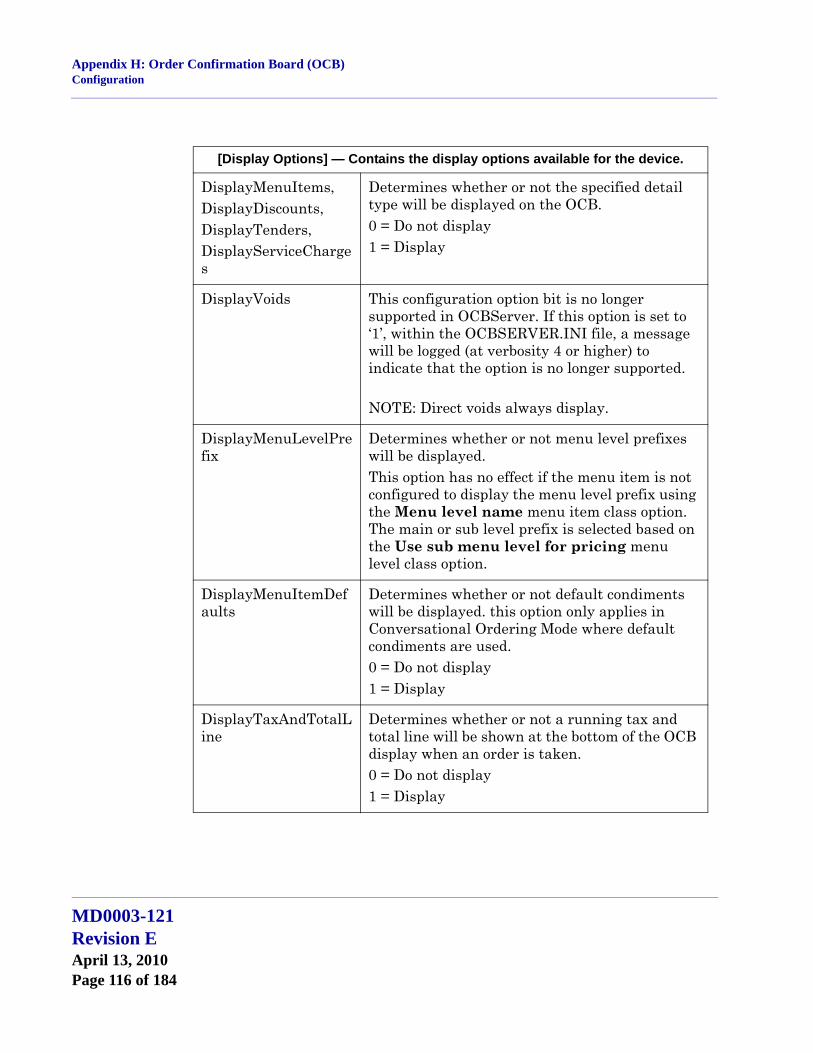
Appendix H: Order Confirmation Board (OCB)Configuration
[Display Options] — Contains the display options available for the device.
DisplayMenuItems,DisplayDiscounts,DisplayTenders,DisplayServiceCharges
Determines whether or not the specified detail type will be displayed on the OCB.0 = Do not display1 = Display
DisplayVoids This configuration option bit is no longer supported in OCBServer. If this option is set to ‘1’, within the OCBSERVER.INI file, a message will be logged (at verbosity 4 or higher) to indicate that the option is no longer supported.
NOTE: Direct voids always display.
DisplayMenuLevelPrefix
Determines whether or not menu level prefixes will be displayed.This option has no effect if the menu item is not configured to display the menu level prefix using the Menu level name menu item class option. The main or sub level prefix is selected based on the Use sub menu level for pricing menu level class option.
DisplayMenuItemDefaults
Determines whether or not default condiments will be displayed. this option only applies in Conversational Ordering Mode where default condiments are used.0 = Do not display1 = Display
DisplayTaxAndTotalLine
Determines whether or not a running tax and total line will be shown at the bottom of the OCB display when an order is taken.0 = Do not display1 = Display
MD0003-121Revision EApril 13, 2010Page 116 of 184

Appendix H: Order Confirmation Board (OCB)Configuration
In addition to the device-specific options, the following set of global options are system-wide and are available in the OCBServer.ini.
Example OCBServer.ini
[Global Options]
CurrencySymbol = "$"
;
; OCB Device Configuration
;
DisplayTotalScreen Determines whether or not the total screen will be displayed. The total screen is displayed after an order has been completed and the associated check on the POS has been service totaled or final tendered. If set to 0, the total screen will be skipped and the display will go directly to the default message screen (WenVIEW) or slide show (AccuVIEW).0 = Do not display1 = Display
DisplayAllCondimentQty
Determines whether or not the condiment quantity will display even if it is a single item. This can be added but it not included in the installed version.0 = Do not display1 = Display
[Display Options] — Contains the display options available for the device.
[Global Options].
CurrencySymbol
Defines the currency symbol displayed with the total due on the total screen. If blank, defaults to ‘$’.
MD0003-121Revision E
April 13, 2010Page 117 of 184

Appendix H: Order Confirmation Board (OCB)Configuration
; DeviceType : 0 = None
; 1 = Texas Digital AccuVIEW
; 2 = Texas Digital WenVIEW
; 3 = Texas Digital AccuVIEWCE
; 4 = Everbrite SNS OCS
; 5 = Micros OCB
;
; ConnectType : 1 = COMPort
; 2 = TCP/IP (Currently supported for Micros OCB only)
;
; IpAddress : IP address [ipaddr:port] of OCB (Micros OCB only)
; ComPort : 1 = COM1, 2 = COM2, etc..
; BaudRate : 1 = 1200, 2 = 9600, 3 = 19200, 4 = 38400, 5 = 57600, 6 = 115200
[OCB1 Device]
DeviceType = 0
ConnectType = 0
ComPort = 0
BaudRate = 0
IpAddress = ""
[OCB2 Device]
DeviceType = 0
ConnectType = 0
ComPort = 0
BaudRate = 0
IpAddress = ""
MD0003-121Revision EApril 13, 2010Page 118 of 184

Appendix H: Order Confirmation Board (OCB)Configuration
;
; Label Defintions
;
[OCB1 Labels]
TotalLabel = "Total: "
TaxLabel = "Tax: "
TotalScreenLine1 = "YOUR"
TotalScreenLine2 = "TOTAL IS"
[OCB2 Labels]
TotalLabel = "TTL: "
TaxLabel = "TX: "
TotalScreenLine1 = "YOUR TOTAL"
TotalScreenLine2 = "IS"
;
; Display Options
;
[OCB1 Display Options]
DisplayMenuItems = 1
DisplayDiscounts = 1
DisplayServiceCharges = 1
DisplayTenders = 1
DisplayVoids = 0
MD0003-121Revision E
April 13, 2010Page 119 of 184
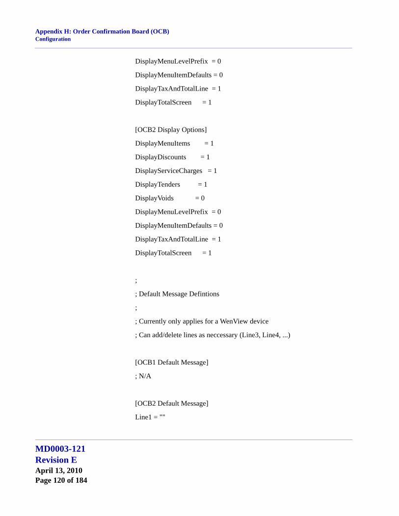
Appendix H: Order Confirmation Board (OCB)Configuration
DisplayMenuLevelPrefix = 0
DisplayMenuItemDefaults = 0
DisplayTaxAndTotalLine = 1
DisplayTotalScreen = 1
[OCB2 Display Options]
DisplayMenuItems = 1
DisplayDiscounts = 1
DisplayServiceCharges = 1
DisplayTenders = 1
DisplayVoids = 0
DisplayMenuLevelPrefix = 0
DisplayMenuItemDefaults = 0
DisplayTaxAndTotalLine = 1
DisplayTotalScreen = 1
;
; Default Message Defintions
;
; Currently only applies for a WenView device
; Can add/delete lines as neccessary (Line3, Line4, ...)
[OCB1 Default Message]
; N/A
[OCB2 Default Message]
Line1 = ""
MD0003-121Revision EApril 13, 2010Page 120 of 184
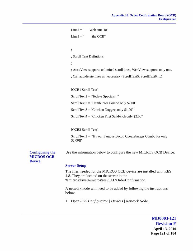
Appendix H: Order Confirmation Board (OCB)Configuration
Line2 = " Welcome To"
Line3 = " the OCB"
;
; Scroll Text Defintions
;
; AccuView supports unlimited scroll lines, WenView supports only one.
; Can add/delete lines as neccessary (ScrollText5, ScrollText6, ...)
[OCB1 Scroll Text]
ScrollText1 = "Todays Specials : "
ScrollText2 = "Hamburger Combo only $2.00"
ScrollText3 = "Chicken Nuggets only $1.00"
ScrollText4 = "Chicken Filet Sandwich only $2.00"
[OCB2 Scroll Text]
ScrollText1 = "Try our Famous Bacon Cheezeburger Combo for only $2.00!!"
Configuring the MICROS OCB Device
Use the information below to configure the new MICROS OCB Device.
Server SetupThe files needed for the MICROS OCB device are installed with RES 4.8. They are located on the server in the %microsdrive%\micros\res\CAL\OrderConfirmation.
A network node will need to be added by following the instructions below.
1. Open POS Configurator | Devices | Network Node.
MD0003-121Revision E
April 13, 2010Page 121 of 184

Appendix H: Order Confirmation Board (OCB)Configuration
2. Select the blue plus icon to add a record.
3. Complete the form by entering the Name, Computer Name, IP Address, Subnet Mask, and by selecting ‘Order Confirmation’ as the Workstation Type.
4. Save the changes.
MICROS OCB Device SetupMICROS OCB devices use the Client Application Loader (CAL) technology to locate, install, and maintain the most up-to-date software programs implemented on the server.
Many settings can be configured in the OCB.ini file. It is installed to %microsdrive%\micros\res\CAL\OrderConfirmation\Packages\OrderConf\Micros\ETC.
To change a setting, simply uncomment it by removing the semicolon ‘;’ and change the data. After saving the file, copy it to the %microsdrive%\micros\res\CAL\OrderConfirmation\Files\CF\Micros\ETC folder.
MD0003-121Revision EApril 13, 2010Page 122 of 184
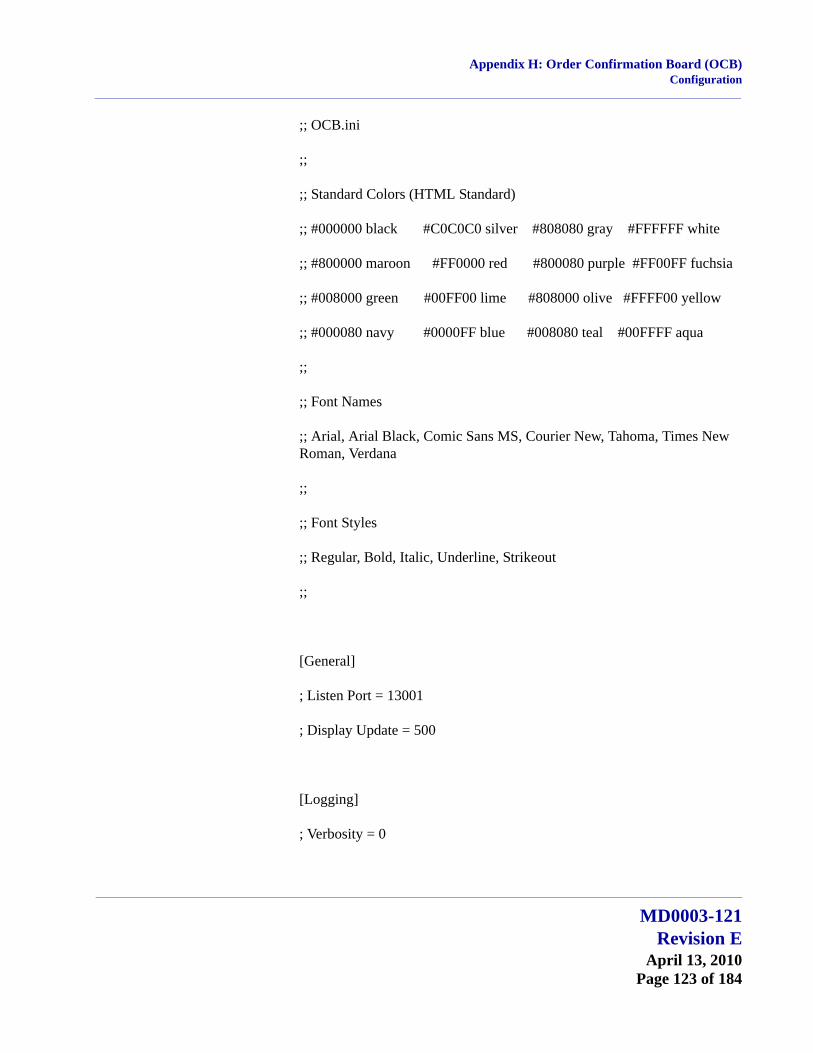
Appendix H: Order Confirmation Board (OCB)Configuration
;; OCB.ini
;;
;; Standard Colors (HTML Standard)
;; #000000 black #C0C0C0 silver #808080 gray #FFFFFF white
;; #800000 maroon #FF0000 red #800080 purple #FF00FF fuchsia
;; #008000 green #00FF00 lime #808000 olive #FFFF00 yellow
;; #000080 navy #0000FF blue #008080 teal #00FFFF aqua
;;
;; Font Names
;; Arial, Arial Black, Comic Sans MS, Courier New, Tahoma, Times New Roman, Verdana
;;
;; Font Styles
;; Regular, Bold, Italic, Underline, Strikeout
;;
[General]
; Listen Port = 13001
; Display Update = 500
[Logging]
; Verbosity = 0
MD0003-121Revision E
April 13, 2010Page 123 of 184
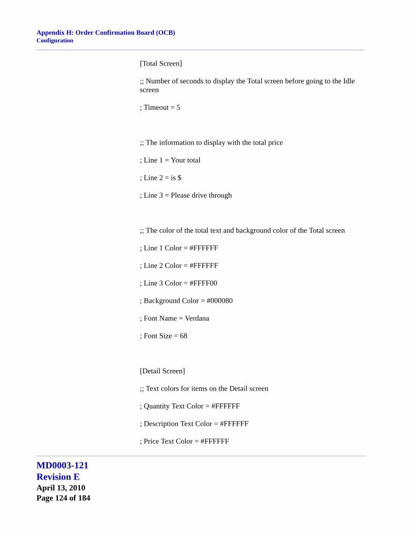
Appendix H: Order Confirmation Board (OCB)Configuration
[Total Screen]
;; Number of seconds to display the Total screen before going to the Idle screen
; Timeout = 5
;; The information to display with the total price
; Line 1 = Your total
; Line 2 = is $
; Line 3 = Please drive through
;; The color of the total text and background color of the Total screen
; Line 1 Color = #FFFFFF
; Line 2 Color = #FFFFFF
; Line 3 Color = #FFFF00
; Background Color = #000080
; Font Name = Verdana
; Font Size = 68
[Detail Screen]
;; Text colors for items on the Detail screen
; Quantity Text Color = #FFFFFF
; Description Text Color = #FFFFFF
; Price Text Color = #FFFFFF
MD0003-121Revision EApril 13, 2010Page 124 of 184

Appendix H: Order Confirmation Board (OCB)Configuration
; Tax Text Color = #FFFF00
; Total Text Color = #FFFF00
; Background Color = #000080
;; The text to display on the Detail screen
; Tax Prompt = Tax $
; Total Prompt = Total $
;; Details about how the detail list is displayed, affects quantity, description, and price
; Font Name = Verdana
; Font Size = 32
; Font Style = Bold
;; Font style for descriptions only, does not affect quantity or price font style
; Combo Font Style = Regular
; Condiment Font Style = Italic
;; Controls degree of indentation for condiments and combo items
;; Set to 0 for no indentation, higher for more indentation
; Indent Level = 2;
MD0003-121Revision E
April 13, 2010Page 125 of 184
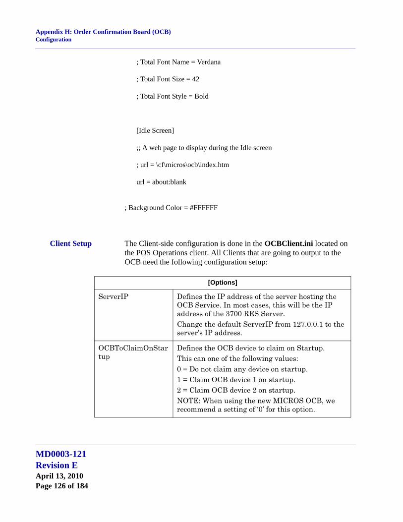
Appendix H: Order Confirmation Board (OCB)Configuration
; Total Font Name = Verdana
; Total Font Size = 42
; Total Font Style = Bold
[Idle Screen]
;; A web page to display during the Idle screen
; url = \cf\micros\ocb\index.htm
url = about:blank
; Background Color = #FFFFFF
Client Setup The Client-side configuration is done in the OCBClient.ini located on the POS Operations client. All Clients that are going to output to the OCB need the following configuration setup:
[Options]
ServerIP Defines the IP address of the server hosting the OCB Service. In most cases, this will be the IP address of the 3700 RES Server.Change the default ServerIP from 127.0.0.1 to the server’s IP address.
OCBToClaimOnStartup
Defines the OCB device to claim on Startup.This can one of the following values:0 = Do not claim any device on startup.1 = Claim OCB device 1 on startup.2 = Claim OCB device 2 on startup.NOTE: When using the new MICROS OCB, we recommend a setting of ‘0’ for this option.
MD0003-121Revision EApril 13, 2010Page 126 of 184

Appendix H: Order Confirmation Board (OCB)Configuration
Example of OCBClient.ini[Options]
ServerIP = “127.0.0.1” ---> Change to the server’s IP address
OCBToClaimOnStartup = 0 ; 0 = NONE, 1 = OCB1, 2 = OCB2
Touchscreens and Macros
To control the functionality of the OCB Interface, most installations will need to have touchscreen buttons and/or macros configured. This section provides a reference list of common configurations. Information provided his is for reference only. Actual selections will vary (and may be modified) based on a site’s requirements.
Touchscreens
User Touchscreen Buttons
1. “Start Lane 1” / “Start Lane 2” — Linked to the Macros defined below or linked directly to the PMS/SIM inquiry.
2. “Claim Lane 1” / “Claim Lane 2” — Linked to the SIM Inquiry Event “Perm. Claim OCB1” (3) or “Perm. Claim OCB2” (4).
3. “Temp Claim Lane 1” / “Temp Claim Lane 2”Linked to the SIM Inquiry Event Temp Claim OCB1 (5) or Temp Claim OCB2 (6)
Manager Touchscreen Buttons
1. “Stop OCB” — Linked to the SIM Inquiry Event “OCB Stop” (2).
2. “Start OCB” — Linked to the SIM Inquiry Event “OCB Start” (1).
3. “Release Lane 1” / “Release Lane 2” — Linked to the SIM Inquiry Event “Release OCB1” (7) or “Release OCB2” (8).
POS Configuration1. In POS Configurator | Devices | Interfaces
Name OCB
MD0003-121Revision E
April 13, 2010Page 127 of 184
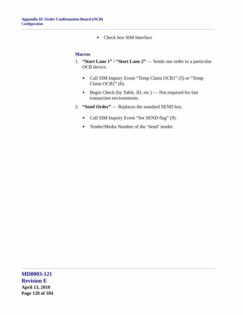
Appendix H: Order Confirmation Board (OCB)Configuration
Check box SIM Interface
Macros1. “Start Lane 1” / “Start Lane 2” — Sends one order to a particular
OCB device.
Call SIM Inquiry Event “Temp Claim OCB1” (5) or “Temp Claim OCB2” (6).
Begin Check (by Table, ID, etc.) — Not required for fast transaction environments.
2. “Send Order” — Replaces the standard SEND key.
Call SIM Inquiry Event “Set SEND flag” (9).
Tender/Media Number of the ‘Send’ tender.
MD0003-121Revision EApril 13, 2010Page 128 of 184
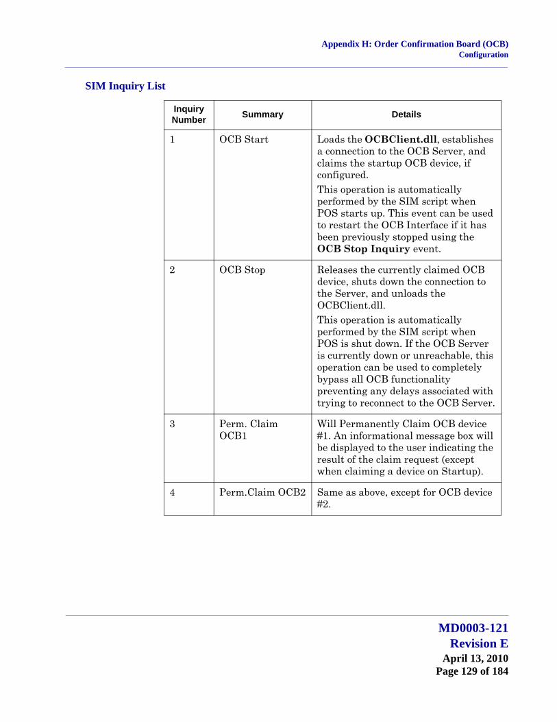
Appendix H: Order Confirmation Board (OCB)Configuration
SIM Inquiry List
Inquiry Number Summary Details
1 OCB Start Loads the OCBClient.dll, establishes a connection to the OCB Server, and claims the startup OCB device, if configured. This operation is automatically performed by the SIM script when POS starts up. This event can be used to restart the OCB Interface if it has been previously stopped using the OCB Stop Inquiry event.
2 OCB Stop Releases the currently claimed OCB device, shuts down the connection to the Server, and unloads the OCBClient.dll. This operation is automatically performed by the SIM script when POS is shut down. If the OCB Server is currently down or unreachable, this operation can be used to completely bypass all OCB functionality preventing any delays associated with trying to reconnect to the OCB Server.
3 Perm. Claim OCB1
Will Permanently Claim OCB device #1. An informational message box will be displayed to the user indicating the result of the claim request (except when claiming a device on Startup).
4 Perm.Claim OCB2 Same as above, except for OCB device #2.
MD0003-121Revision E
April 13, 2010Page 129 of 184
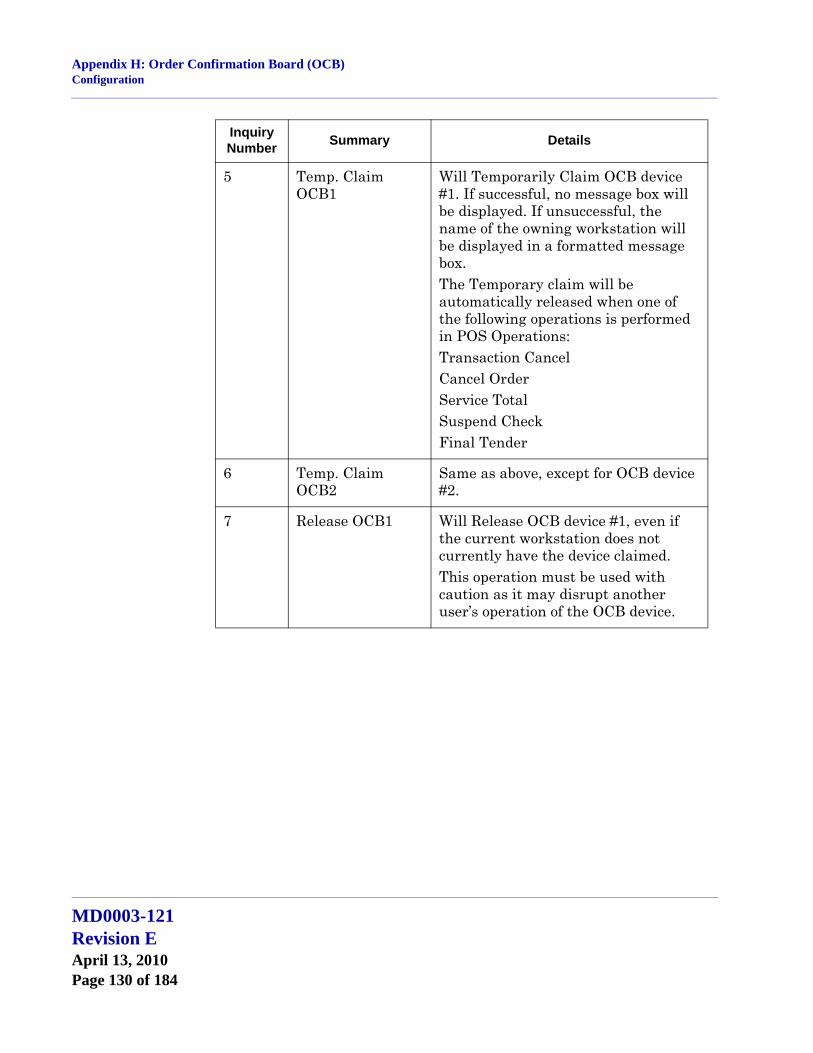
Appendix H: Order Confirmation Board (OCB)Configuration
5 Temp. Claim OCB1
Will Temporarily Claim OCB device #1. If successful, no message box will be displayed. If unsuccessful, the name of the owning workstation will be displayed in a formatted message box. The Temporary claim will be automatically released when one of the following operations is performed in POS Operations:Transaction CancelCancel OrderService TotalSuspend CheckFinal Tender
6 Temp. Claim OCB2
Same as above, except for OCB device #2.
7 Release OCB1 Will Release OCB device #1, even if the current workstation does not currently have the device claimed. This operation must be used with caution as it may disrupt another user’s operation of the OCB device.
Inquiry Number Summary Details
MD0003-121Revision EApril 13, 2010Page 130 of 184
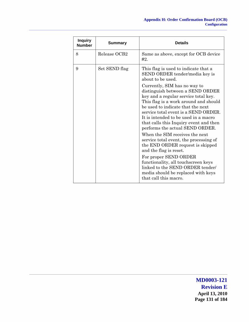
Appendix H: Order Confirmation Board (OCB)Configuration
8 Release OCB2 Same as above, except for OCB device #2.
9 Set SEND flag This flag is used to indicate that a SEND ORDER tender/media key is about to be used. Currently, SIM has no way to distinguish between a SEND ORDER key and a regular service total key. This flag is a work around and should be used to indicate that the next service total event is a SEND ORDER. It is intended to be used in a macro that calls this Inquiry event and then performs the actual SEND ORDER.When the SIM receives the next service total event, the processing of the END ORDER request is skipped and the flag is reset. For proper SEND ORDER functionality, all touchscreen keys linked to the SEND ORDER tender/media should be replaced with keys that call this macro.
Inquiry Number Summary Details
MD0003-121Revision E
April 13, 2010Page 131 of 184
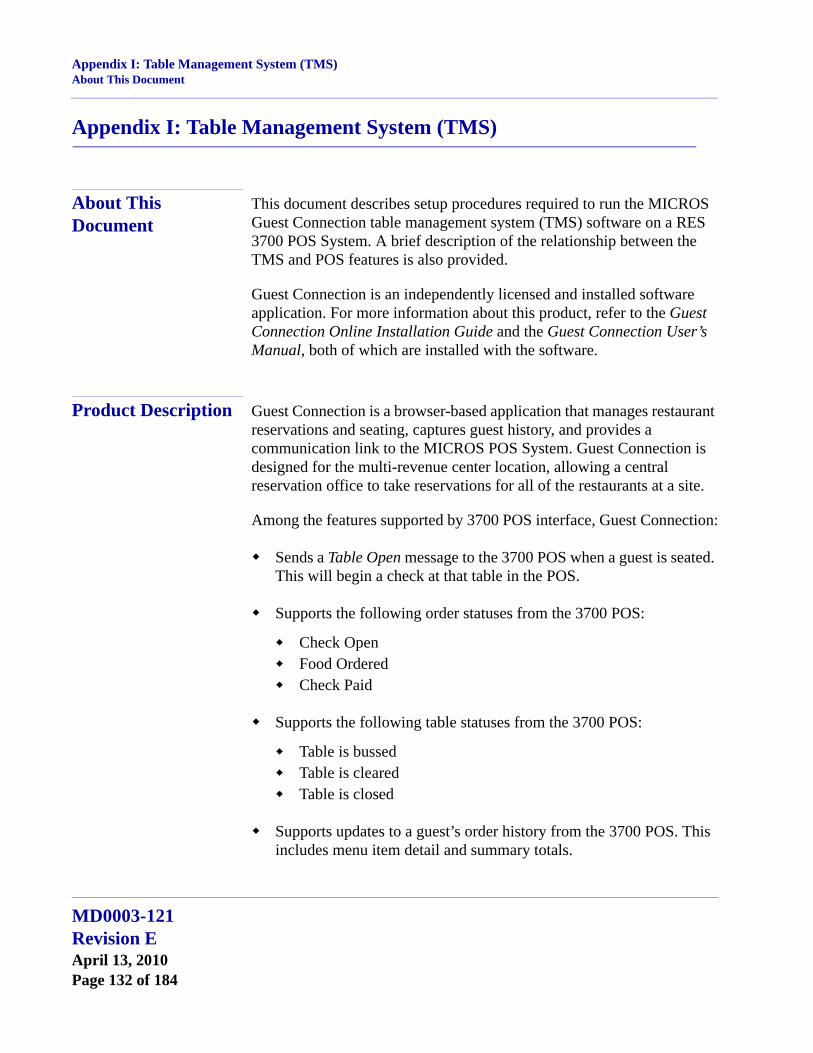
Appendix I: Table Management System (TMS)About This Document
Appendix I: Table Management System (TMS)
About This Document
This document describes setup procedures required to run the MICROS Guest Connection table management system (TMS) software on a RES 3700 POS System. A brief description of the relationship between the TMS and POS features is also provided.
Guest Connection is an independently licensed and installed software application. For more information about this product, refer to the Guest Connection Online Installation Guide and the Guest Connection User’s Manual, both of which are installed with the software.
Product Description Guest Connection is a browser-based application that manages restaurant reservations and seating, captures guest history, and provides a communication link to the MICROS POS System. Guest Connection is designed for the multi-revenue center location, allowing a central reservation office to take reservations for all of the restaurants at a site.
Among the features supported by 3700 POS interface, Guest Connection:
Sends a Table Open message to the 3700 POS when a guest is seated. This will begin a check at that table in the POS.
Supports the following order statuses from the 3700 POS:
Check OpenFood OrderedCheck Paid
Supports the following table statuses from the 3700 POS:
Table is bussedTable is clearedTable is closed
Supports updates to a guest’s order history from the 3700 POS. This includes menu item detail and summary totals.
MD0003-121Revision EApril 13, 2010Page 132 of 184

Appendix I: Table Management System (TMS)Product Description
Limitations The following limitations should be noted between the Guest Connection and 3700 POS:
3700 POS does not send the following order statuses:
Check PrintedCourse OrderedCourse fired
3700 POS does not accept the cancel or unseat message from Guest Connection. If a guest is unseated from a table in Guest Connection, the 3700 POS open check must be closed from within that application.
Add/transfer messages are not accepted between 3700 POS and Guest Connection. When an add/transfer is done in one of the applications, the same procedure will need to be done on the other side. These functions are not supported from the 3700 POS:
SIM Inquire 4 — Transfer
SIM Inquire 5 — Add Check/Extend a Table
Guest Connection supports only one check at a table. However, once a check is opened in Guest Connection, the POS user can split it or even add more checks to the open table. This can cause the following problems when a check is closed at that table:
On the Guest Connection side, the system accepts updates from the 3700 POS based on table number. Once the first check is paid, Guest Connection shows the table as paid, alerting the hostess to have the table cleared. This can cause confusion.
Example:
1. In Guest Connection, start a check at Table 10. The 3700 POS will automatically begin Check 10/1.
2. On the 3700 POS side, start another check at table 10. The check will be labeled, 10/2.
3. Close Check 10/2. The POS will send a check paid message to
MD0003-121Revision E
April 13, 2010Page 133 of 184
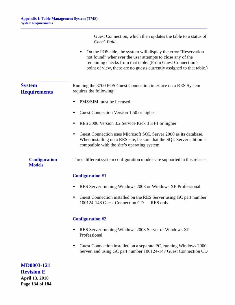
Appendix I: Table Management System (TMS)System Requirements
Guest Connection, which then updates the table to a status of Check Paid.
On the POS side, the system will display the error “Reservation not found” whenever the user attempts to close any of the remaining checks from that table. (From Guest Connection’s point of view, there are no guests currently assigned to that table.)
System Requirements
Running the 3700 POS Guest Connection interface on a RES System requires the following:
PMS/SIM must be licensed
Guest Connection Version 1.50 or higher
RES 3000 Version 3.2 Service Pack 3 HF1 or higher
Guest Connection uses Microsoft SQL Server 2000 as its database. When installing on a RES site, be sure that the SQL Server edition is compatible with the site’s operating system.
Configuration Models
Three different system configuration models are supported in this release.
Configuration #1
RES Server running Windows 2003 or Windows XP Professional
Guest Connection installed on the RES Server using GC part number 100124-148 Guest Connection CD — RES only
Configuration #2
RES Server running Windows 2003 Server or Windows XP Professional
Guest Connection installed on a separate PC, running Windows 2000 Server, and using GC part number 100124-147 Guest Connection CD
MD0003-121Revision EApril 13, 2010Page 134 of 184

Appendix I: Table Management System (TMS)TMS Installation
Configuration #3
RES Server running Windows 2003 Server or Windows XP Professional
Guest Connection installed on a separate PC, running Windows 2000 Professional, and using GC part number 100124-148 Guest Connection CD — RES only
TMS Installation The 3700 Guest Connection interface is dependent on the version of RES 3.2 software. The interface is installed with the RES 4.x software. When installing RES 4.x be certain to select the TMS Interface option.
The interface is only installed on the RES Server. Once the software is installed, refer to the next section, System Setup, for instructions on configuring the 3700 interface.
Configuring the 3700 POS
To use Guest Connection on a RES 3700 POS System, users must establish a SIM interface to Guest Connection and set up an appropriate number of touch keys in POS Operations. The procedures for doing so are as follows:
Create the Interface
1. Open the POS Configurator and go to Devices | Interfaces | General.
2. Add a Guest Connection record with the following properties:
Outgoing Message Name — TMS 3700
Timeout — 20
Network Node — Server
Number ID Digits — 9
Backup Interface — (n/a)
Log Transactions — (not necessary)
SIM Interface — (must be checked)
Interface Type — TCP
MD0003-121Revision E
April 13, 2010Page 135 of 184
Appendix I: Table Management System (TMS)Configuring the 3700 POS
3. Go to the Interfaces tab and enter the following:
TCP Server Name — Enter the IP address of the RES Server.
TCP Port Number — 5012
4. Save the record. Go to Devices | Touchscreen Designer.
5. Select the appropriate screen(s) on which to add the three SIM Inquire keys required for Guest Connection. Configure each key as follows:
Legend — Enter the button name
Category — SIM/PMS Inquire
Interface — Guest Connection
Inquire Number — Enter the number that corresponds to the selected SIM function:
1 — Bus/Clear Table
2 — Clean
3 — Close
6. Save and go to Revenue Center | RVC Table Seating and confirm that tables have been set up for each revenue center. If corresponding table numbers are not programmed, Guest Connection will be unable to initiate a guest check on the 3700 POS when a guest is seated.
7. Save and close POS Configurator.
Note Touchscreen locations for SIM keys is subject to the needs and preferences of the user. MICROS recommends placing Inquires 1-3 on the Table Layout Screen, as they may be used without opening a check.
The SIM Functions Bus/Clear, Clean, and Close are revenue center-based. A user must be sign into the correct revenue center at the POS when performing one of these functions.
MD0003-121Revision EApril 13, 2010Page 136 of 184

Appendix I: Table Management System (TMS)Configuring the 3700 POS
8. On the RES Server, open the Window’s Explorer and navigate to the \Micros\RES\POS\etc folder.
9. Rename the TMSInterface.isl to pms#.isl, where # is the number of the TMS 3700 interface created for Guest Connection in POS Configurator | Devices | Interfaces.
For example: If the TMS 3700 interface was number 2 on the Interface form, then the TMSInterface.isl script should be renamed pms2.isl.
10. Copy the pms#.isl file to the \MICROS\res\pos\etc folder onto the RES server. This file will need to be loaded onto all POS clients as well. Use the CAL file structure to copy the file to the etc folder on each client platform installed.
Editing the Interface File
1. Open the TMSInterface.ini file and change the following settings to match the user’s system:
[SETTINGS]
UWSSEQ —The uws_seq from micros.uws_def of the 3700 Server.
MD0003-121Revision E
April 13, 2010Page 137 of 184
Appendix I: Table Management System (TMS)Configuring the 3700 POS
[TMS-CONNECTION]
port — This is the port that allows Guest Connection to send/receive messages from the 3700 POS. This entry must match the MICROSPORT value in Guest Connection (Maintenance | Look Ups | System | PARAM).
ip — The IP address of the server where the Guest Connection interface service (GC2MICROS.exe) is installed.
[3700-CONNECTION]
port — This is the port that allows each 3700 POS client to send/receive messages from the RES Interface Server. This value must match the TCP Port Number defined in POS Configurator | Devices | Interfaces for the Guest Connection interface.
2. Copy the tmsinterface.ini file to the \MICROS\res\pos\etc folder on the server.
3. From the Windows Start menu, go to Settings | Control Panel | Administrative Tools | Services.
4. Right-click on Micros TMS Interface and select Properties.
5. Change the Startup Type to Automatic. The next time the system is rebooted, the interface will startup automatically. To activate immediately, right-click on MICROS TMS Interface and select Start.
The service will write messages to the 3700d.log file. This file can be viewed using logviewer. To view every message sent between the 3700 and Guest Connection, set Verbosity to 10 in the Control Panel.
6. Perform a warm boot (restart) of the system.
Note Guest Connection is installed with port 5100 as the default setup value, which is already assigned in RES 3000 to the Cash Management application.
To avoid a conflict, Guest Connection users must change the port setting to 5200 or another unassigned value.
MD0003-121Revision EApril 13, 2010Page 138 of 184
Appendix I: Table Management System (TMS)Recommended Options
Recommended Options
In the 3700 POS Configurator
Open POS Configurator and enable the option One check per table (Revenue Center | RVC Transactions).
In Guest Connection
Change the MICROSPORT value to 5200 (Maintenance | Look Ups | System | PARAM | Page 2).
Change the MICROS GUID to N (no) (Maintenance | Look Ups | System | PARAM). The default value is Y.
Change the CODE 1 value to “Food Ordered” (Maintenance | Look Ups | General | TABLESTAT.
MD0003-121Revision E
April 13, 2010Page 139 of 184
Appendix I: Table Management System (TMS)Shared Procedures
Shared Procedures Guest checks can be initiated by either Guest Connection or POS Operations. MICROS recommends starting it in Guest Connection, unless the table will be splitting the check. This allows the hostess to control the table seating.
When entered through Guest Connection, the interface also begins a check in 3700 POS, passing the employee number, table number, and guest count assigned in Guest Connection. Once the POS has started the check, it passes back a message to Guest Connection updating the table status to Check Begun.
Similarly, when a check is started from the 3700 POS, the information is sent to the Guest Connection and the table is assigned a status of Check Begun.
Once started, the updated check information is available from either application.
Changing the Status
Once menu items are ordered and the check is service totaled for the first time, the system updates Guest Connection with a table status of Appetizers Ordered. Since the 3700 POS cannot send multiple courses, MICROS recommends changing the descriptor to Items Ordered.
When a check is final tendered through 3700 POS, the interface updates the table status in Guest Connection to Check Paid and, if configured to do so, sends Guest Connection the check’s menu item detail.
At that point, the table should be cleaned, either through the 3700 POS or Guest Connection. The busser should then update the table status to Table Bussed through the 3700 POS.
When a table is no longer required, it’s status can be set to Table Closed. This applies to single tables or sections. The function may be performed from either the 3700 POS or Guest Connection.
MD0003-121Revision EApril 13, 2010Page 140 of 184
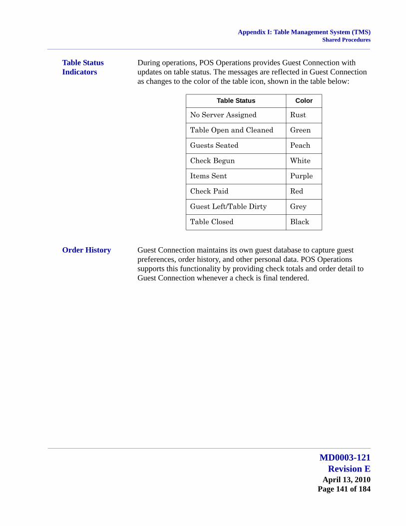
Appendix I: Table Management System (TMS)Shared Procedures
Table Status Indicators
During operations, POS Operations provides Guest Connection with updates on table status. The messages are reflected in Guest Connection as changes to the color of the table icon, shown in the table below:
Order History Guest Connection maintains its own guest database to capture guest preferences, order history, and other personal data. POS Operations supports this functionality by providing check totals and order detail to Guest Connection whenever a check is final tendered.
Table Status Color
No Server Assigned Rust
Table Open and Cleaned Green
Guests Seated Peach
Check Begun White
Items Sent Purple
Check Paid Red
Guest Left/Table Dirty Grey
Table Closed Black
MD0003-121Revision E
April 13, 2010Page 141 of 184

Appendix J: Customized Installation ProceduresIntroduction
Appendix J: Customized Installation Procedures
Introduction This section provides information for sites with complicated Client/Server setups that require customized installation.
Registry Settings There are two registry settings that affect the RES patch. They are:
HKLM\Software\Micros\Patch\BypassDBUpdate (True) :STRING
HKLM\Software\Micros\Patch\BypassReboot (True) :STRING
These values must be set to True in order for them to work.
BypassDBUpdateThe existence of this registry value will cause the RES patch to bypass the database update portion of the patch.
BypassRebootThe existence of this value will cause the RES patch to bypass the execution of Shutdown.exe. The patch will simply stop. The Server will not reboot.
If running MICROS Desktop, the BypassReboot setting should NOT be used as this will leave the system on but disabled. The only recourse at that point is to reboot the server using the power button.
MD0003-121Revision EApril 13, 2010Page 142 of 184

Appendix K: Pre and Post Custom Installation ProceduresIntroduction
Appendix K: Pre and Post Custom Installation Procedures
A custom pre and post update hook has been added to allow an integrator to add their own install processes to the patch installation process.
When running a patch upgrade on the RES Server, the system can be setup to execute a batch file before the patch is started or before the patch is finished. These batch files cannot be used to reboot the system. They can be used to stop third party services that affect the RES system.
Follow these steps to create a custom file that can be called while a MICROS patch is running:
1. In the server's registry, go to HKLM\Software\Micros and add a key called Patch.
2. Create a string value for this key and name it either CustomPreUpdate or CustomPostUpdate, depending on when it will be executed.
CustomPreUpdate will occur at the beginning of the patch. Use this key to shut down non-Micros services at this time (see Step 3).
CustomPostUpdate will run after all files have been updated, but before the database is updated.
3. Set the value of CustomPreUpdate to the location of the file you want to call (e.g., C:\Temp\StopService.bat).
4. Set the value of CustomPostUpdate to the location of the file you want to call (e.g., C:\temp\InstallCustomReports.bat).
MD0003-121Revision E
April 13, 2010Page 143 of 184

Appendix L: Removing RES 3.x SoftwareIntroduction
Appendix L: Removing RES 3.x Software
Introduction This section provides instructions on removing RES 3.2 from the server and clients.
This is a required step if you are upgrading from RES Version 3.x to RES 4.x. Attempting installation before removing RES 3.x will cause setup to stop.
From RES 3.2 Server
Follow these steps to remove MICROS software from a server running Version 3.2 or lower:
1. From the Windows Start Menu, select Programs | MICROS Applications | MICROS Control Panel to launch the interface.
2. Click the button to set the Restaurant to OFF.
3. From the Windows Start Menu, select Settings | Control Panel | Administrative Tools | Services. Stop all MICROS services, including those not installed by RES GR. Specifically:
MICROS 3700 System
MICROS Caller ID Service
MICROS Distributed Service Manager
MICROS Secure Desktop
MICROS LM Com Scheduler
and the non-RES services:
ValueLink, Watchdog, Agent, etc.
4. Select Add/Remove Programs. Highlight and remove all MICROS programs (e.g., EM, ValueLink) except for RES. (RES will be removed in Step 11.)
MD0003-121Revision EApril 13, 2010Page 144 of 184

Appendix L: Removing RES 3.x SoftwareIntroduction
5. (Optional) If ValueLink is installed, open Windows Explorer and navigate to the WinNT\system32 folder. Save the vlink.cfg file to a safe location.
6. Open a DOS window. From the command line, navigate to the \MICROS\res\pos\bin directory. Enter the following commands to remove the Connection Advisor service:
connadvisor –uninstall
connadvisor –unregister
7. Select Start | Run | Regedit to open the Registry.
8. Go to My Computer\HKey_Local_Machine\System\Current ControlSet\Services and delete those MICROS services that were not installed by RES GR.
9. Go to HKey_Local_Machine\Software\MICROS\Common and highlight LicenseManager. From the menu bar, select Registry | Export Registry File... to save the license codes to a safe location, outside the MICROS tree.
10. Open the Windows Explorer and navigate to the MICROS\ Database\Data folder. Save the micros.db and micros.log to safe location.
11. Return to Settings | Control Panel | Add/Remove Programs to remove the MICROS RES 3.2 software.
12. Go back to Windows Explorer and manually delete the MICROS tree.
13. In the Registry, go to My Computer\HKey_Local_Machine and delete the following:
Software\MICROS
Software\Borland
Software\ODBC\odbc.ini\micros
Software\ODBC\odbc.ini\microsOld
MD0003-121Revision E
April 13, 2010Page 145 of 184

Appendix L: Removing RES 3.x SoftwareIntroduction
Software\ODBC\odbc.ini\microsSetup
Software\ODBC\odbc.ini\ODBC Data Sources
Software\ODBC\odbcInst.ini\Adaptive Server Anywhere 6.0
Software\ODBC\odbcInst.ini\Adaptive Server Anywhere 6.0 Translator
Software\ODBC\odbcInst.ini\ODBC Drivers\Adaptive Server Anywhere 6.0
Software\ODBC\odbcInst.ini\ODBC Translators\Adaptive Server Anywhere 6.0 Translator
System\CurrentControlSet\Services\3700d
System\CurrentControlSet\Services\Micros Backup Server
System\CurrentControlSet\Services\Micros CAL Service
System\CurrentControlSet\Services\CISERVICE
System\CurrentControlSet\Services\svcCashManager
System\CurrentControlSet\Services\MicrosCashManagementComServer
System\CurrentControlSet\Services\srvConnAdvisor
System\CurrentControlSet\Services\Micros Database Service
System\CurrentControlSet\Services\DbUpdateServer
System\CurrentControlSet\Services\MICROS Distributed Service Manager
System\CurrentControlSet\Services\svcCOMScheduler
System\CurrentControlSet\Services\srvMDSHTTPService
System\CurrentControlSet\Services\MicrosDesk
System\CurrentControlSet\Services\SQLANYs_sql (Server Name)
MD0003-121Revision EApril 13, 2010Page 146 of 184
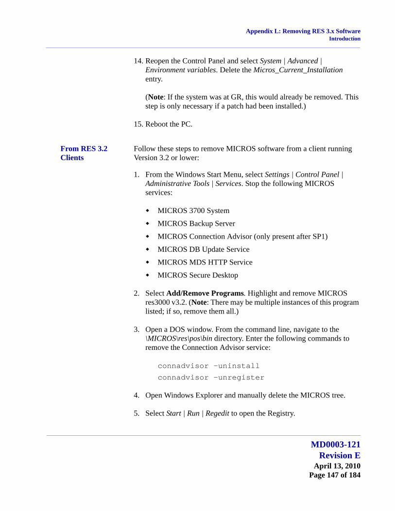
Appendix L: Removing RES 3.x SoftwareIntroduction
14. Reopen the Control Panel and select System | Advanced | Environment variables. Delete the Micros_Current_Installation entry.
(Note: If the system was at GR, this would already be removed. This step is only necessary if a patch had been installed.)
15. Reboot the PC.
From RES 3.2 Clients
Follow these steps to remove MICROS software from a client running Version 3.2 or lower:
1. From the Windows Start Menu, select Settings | Control Panel | Administrative Tools | Services. Stop the following MICROS services:
MICROS 3700 System
MICROS Backup Server
MICROS Connection Advisor (only present after SP1)
MICROS DB Update Service
MICROS MDS HTTP Service
MICROS Secure Desktop
2. Select Add/Remove Programs. Highlight and remove MICROS res3000 v3.2. (Note: There may be multiple instances of this program listed; if so, remove them all.)
3. Open a DOS window. From the command line, navigate to the \MICROS\res\pos\bin directory. Enter the following commands to remove the Connection Advisor service:
connadvisor –uninstall
connadvisor –unregister
4. Open Windows Explorer and manually delete the MICROS tree.
5. Select Start | Run | Regedit to open the Registry.
MD0003-121Revision E
April 13, 2010Page 147 of 184
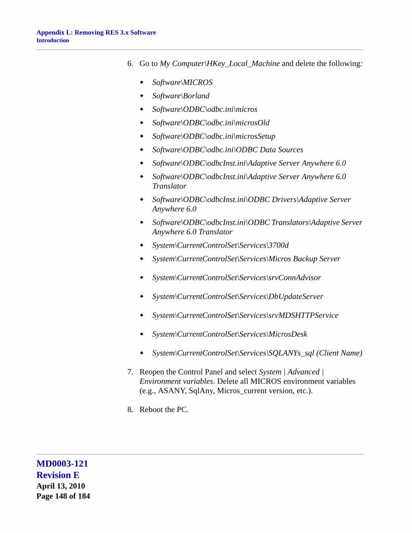
Appendix L: Removing RES 3.x SoftwareIntroduction
6. Go to My Computer\HKey_Local_Machine and delete the following:
Software\MICROS
Software\Borland
Software\ODBC\odbc.ini\micros
Software\ODBC\odbc.ini\microsOld
Software\ODBC\odbc.ini\microsSetup
Software\ODBC\odbc.ini\ODBC Data Sources
Software\ODBC\odbcInst.ini\Adaptive Server Anywhere 6.0
Software\ODBC\odbcInst.ini\Adaptive Server Anywhere 6.0 Translator
Software\ODBC\odbcInst.ini\ODBC Drivers\Adaptive Server Anywhere 6.0
Software\ODBC\odbcInst.ini\ODBC Translators\Adaptive Server Anywhere 6.0 Translator
System\CurrentControlSet\Services\3700d
System\CurrentControlSet\Services\Micros Backup Server
System\CurrentControlSet\Services\srvConnAdvisor
System\CurrentControlSet\Services\DbUpdateServer
System\CurrentControlSet\Services\srvMDSHTTPService
System\CurrentControlSet\Services\MicrosDesk
System\CurrentControlSet\Services\SQLANYs_sql (Client Name)
7. Reopen the Control Panel and select System | Advanced | Environment variables. Delete all MICROS environment variables (e.g., ASANY, SqlAny, Micros_current version, etc.).
8. Reboot the PC.
MD0003-121Revision EApril 13, 2010Page 148 of 184
Appendix M: RES Security StandardIntroduction
Appendix M: RES Security Standard
RES versions 4.0 and higher contain a comprehensive data security package. The RES security features described in this section address vulnerability concerns in an increasingly complex and rapidly changing technical environment.
The MICROS security standard implements strong data encryption at the application level to protect sensitive data wherever it resides on, or is transmitted within, the RES System. By targeting the application level, the MICROS solution eliminates problems associated with hardware- or transmission-specific processes and protocols. This allows sites to retain their existing hardware or network infrastructure as long as it meets MICROS RES minimum system requirements. In many cases, hardware- or protocol-level security can be enabled as an added means to secure sensitive data.
This section provides an overview of the RES Security Standard and discusses the areas that are affected by the changes. Topics covered include:
Employee Security
System Security
Electronic Payments
Additionally, beginning with RES Version 4.3 Hotfix 1, a site must be PCI-compliant in order for POS Operations to start successfully. A detailed description of this feature is provided in the PCI Compliance Verified at System Startup section on page 179.
Note Product design alone does not ensure system security. MICROS customers also bear responsibility for implementing their own security policies and procedures with regard to hiring practices, system access, and network firewalls.
MD0003-121Revision E
April 13, 2010Page 149 of 184
Appendix M: RES Security StandardEmployee Security
Employee Security For security, the 3700 POS System includes options that limit employee access to forms and records in the configuration tools and to certain keys and functions during system operations. Access is restricted by assigning privileges to each employee class.
UsageAccess privileges are used to limit what an employee can see and do in the POS system. The primary mechanism for restricting access is through privilege levels, which are assigned by employee class. Privilege levels control access to menu items, discounts, tender/media, service charges, Manager Procedures, the POS Configurator, system clock-in, and autosequences.
Example
Jeff's Café is located on a street corner with busy pedestrian traffic on two sides. With so much activity, it's hard to keep tabs on all the tables and the restaurant is occasionally troubled by walk-out customers. The manager needed a method for closing these checks, but didn't want the wait staff to have access to this function. The solution was to program a [Tender/Media] key for walk-outs and to assign it a higher privilege level than the one granted to wait staff.
Because employees at the same privilege level could have access to each other's records, a secondary security mechanism was added to the system. This mechanism allows you to specify whether members of an employee class will have unrestricted access to each other's records, access to employees at the same level or below, or access to employees at a lower level only. Both POS Configurator and Manager Procedures are affected by the selection.
MD0003-121Revision EApril 13, 2010Page 150 of 184

Appendix M: RES Security StandardEmployee Security
ConfigurationThe configuration section is divided as follows:
Establishing Privilege Levels
Setting Configurator Access
Restricting Access to Employee Data
Establishing Privilege LevelsFollow these steps to establish privilege levels for employees:
1. Open POS Configurator and go to the Employees | Employee Classes form.
2. Select the Name of an employee class from the table.
3. Go to the Privileges | Privilege Level tab.
4. From each of the drop-down lists, specify a privilege level for this employee class.
Privilege Levels are ranked on a scale from 0-3, where 0 is the lowest and 3 is the highest level assigned. In general, assigning a privilege level means that employees of this class will have access to all records, keys, and operations associated with that level and lower.
5. Save all changes.
Setting Configurator AccessFollow these steps to set the configurator access for an employee level:
1. Open POS Configurator and select Employees | Configurator Access.
2. Add a new record in the table.
3. In the Employee Class column, double-click to open the drop-down list and select one of the available employee classes.
MD0003-121Revision E
April 13, 2010Page 151 of 184
Appendix M: RES Security StandardEmployee Security
4. In the POScfg Form column, double-click to open the drop-down list and select the form that members of the employee class may access.
5. Under Access Privileges, indicate the actions that may be performed on this form(s). Options include:
Allow read
Allow update
Allow insert
Allow delete
6. Save all changes.
Restricting Access to Employee DataFollow these steps to restrict all employee classes’ access to employee data:
1. Open POS Configurator and go to System | Restaurant | Options.
2. Under Restrict Access To Employee Data, select one of the following options:
No access limitation
Same level or lower
Lower level only
To set this option, an employee must have been assigned a level 3 on the Employee Class | Privilege Levels form in the Mgr Procedures/POS Config drop-down list. Otherwise, these options will not be displayed.
3. Save all changes.
MD0003-121Revision EApril 13, 2010Page 152 of 184
Appendix M: RES Security StandardSystem Security
System Security Managing the system in a way that minimizes risk is critical to ensuring database security. The System Security section is divided into two sections, Overview and Configuration.
Overview
Encryption
Password Management
Security Log
Risk Management
Configuration
Overview EncryptionSecuring the system involves protecting two types of data:
Data at Rest — Refers to data stored on persistent media, such as the system database or in the operating system’s file system.
Data in Transit — Refers to data transmitted from one computer process to another, where the process resides on different computers and the data must be transmitted across a network.
To secure data in these states, RES employs strong data encryption using industry-standard algorithms such as 3DES and AES. These algorithms are based on a complex system of mathematics that are used to scramble the original data, rendering it unreadable to anyone outside the secure system. The encryption mechanism includes the creation and storage of one or more software ‘keys’ that are used to encrypt and decrypt the data.
Current encryption algorithms are divided into two classes:
Symmetric — Uses a single key to both encrypt and decrypt the data. This is the faster, though less secure method.
MD0003-121Revision E
April 13, 2010Page 153 of 184

Appendix M: RES Security StandardSystem Security
Asymmetric — Uses separate but related keys (also referred to as a key pair), one to encrypt and one to decrypt the data. Functions are not assigned. That is, either key may be used to encrypt, but its opposite MUST be used to decrypt the results. This is the slower, more secure method.
Encrypted AreasThe RES 4.x systems include a number of data storage and relay components where data are accessible. For this reason, data encryption is applied in multiple layers across the following areas:
Data at RestRES stores information (data at rest) in three areas: 1) the in-store database, 2) the backup server database, and 3) the SAR client (stand-alone resilience) database. Each of these areas contains both sensitive and non-sensitive information. The server retains a copy of all three, but only the last two are kept locally on each client.
The in-store database is a long-term storage component for the site’s data. The majority of information stored by RES is considered non-sensitive. That is, it includes all the options necessary to configure and run the program (touchscreen layouts, number of devices, business settings, etc.), as well as the historical transaction data (items, quantities, prices) gathered in the course of business.
Sensitive data refers to personal credit card information (customer names, account numbers, expiration dates) that are protected by law and must be guarded against accidental or improper disclosure.
For the in-store database, RES 4.x encrypts the entire database using standard AES encryption. This process is transparent to applications that are working within the RES system and are authorized to access the database via standard SQL tools. The encryption of the database file prevents unauthorized access through binary editors and/or hex dump utilities.
MD0003-121Revision EApril 13, 2010Page 154 of 184
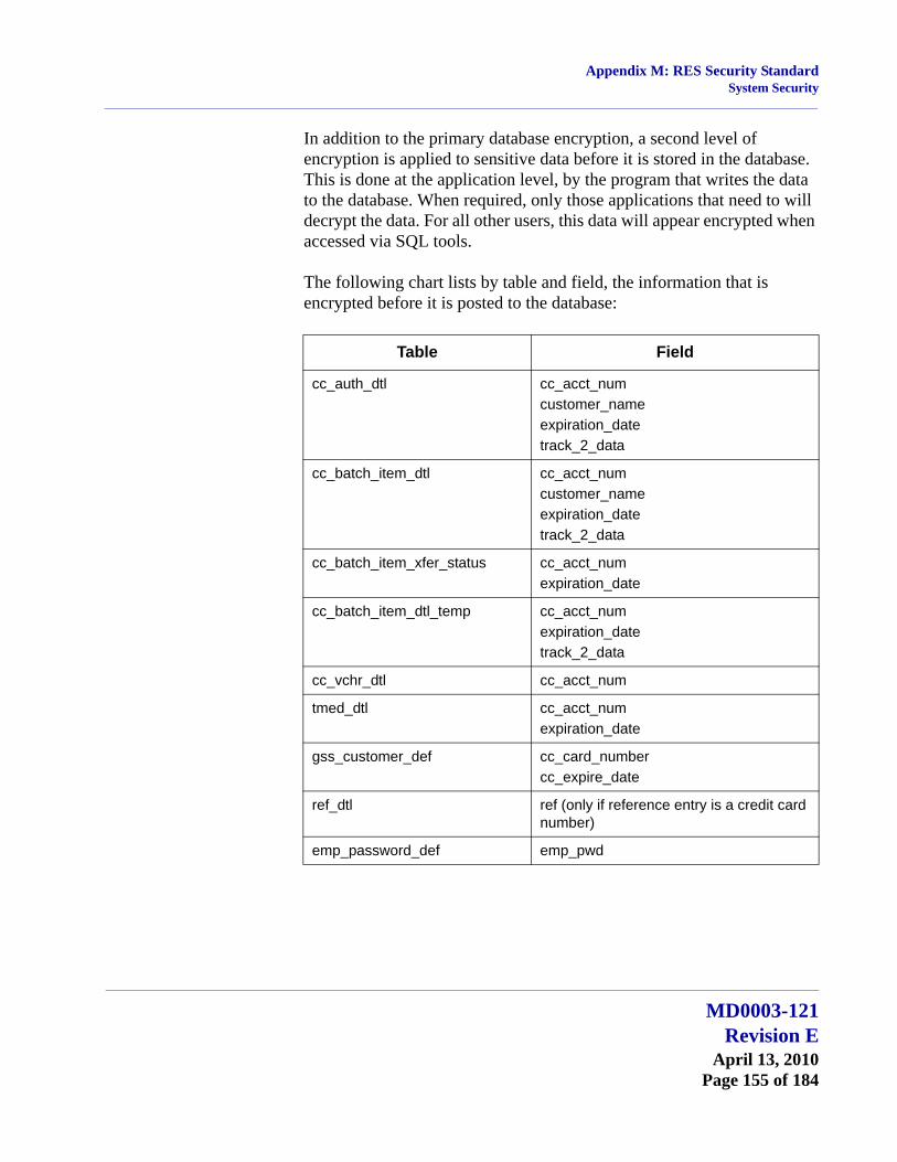
Appendix M: RES Security StandardSystem Security
In addition to the primary database encryption, a second level of encryption is applied to sensitive data before it is stored in the database. This is done at the application level, by the program that writes the data to the database. When required, only those applications that need to will decrypt the data. For all other users, this data will appear encrypted when accessed via SQL tools.
The following chart lists by table and field, the information that is encrypted before it is posted to the database:
Table Field
cc_auth_dtl cc_acct_numcustomer_nameexpiration_datetrack_2_data
cc_batch_item_dtl cc_acct_numcustomer_nameexpiration_datetrack_2_data
cc_batch_item_xfer_status cc_acct_numexpiration_date
cc_batch_item_dtl_temp cc_acct_numexpiration_datetrack_2_data
cc_vchr_dtl cc_acct_num
tmed_dtl cc_acct_numexpiration_date
gss_customer_def cc_card_numbercc_expire_date
ref_dtl ref (only if reference entry is a credit card number)
emp_password_def emp_pwd
MD0003-121Revision E
April 13, 2010Page 155 of 184

Appendix M: RES Security StandardSystem Security
RES versions 4.0 and higher, address the problem of data temporarily stored on a workstation, including devices configured for Standalone Resiliency (SAR) or Backup Server Mode (BSM), by applying RSA encryption to the sensitive data before storing it in temporary files on the RES client. These temporary files are only retained for a short period of time before being deleted from the system.
Data In TransitDuring operations, data passes from the encrypted in-store database to a RES workstation and back. Typically, data is transported across a closed system such as a private LAN. This does not guarantee that the network is secure — particularly if the LAN includes wireless devices.
To address this issue, a separate transport key is used to encrypt all sensitive data before it is passed along the network. This is done at the application level and prevents unauthorized users from deciphering the files, regardless of how they are transported (LAN, WAN, WiFi). For added security, hardware- and transport-level protocols such as IPSEC, WEP, and WPA can be used to further encrypt transmissions.
Key Generation and StorageThe RES security paradigm requires the use of encryption keys in three areas:
Encryption of the database.
Encryption of the sensitive fields in the database.
Encryption of sensitive data transmitted over the network.
Encryption keys are generated by inputting a pass-phrase and a series (typically 12 or more) of random bits known as a Salt value into a key derivation function or algorithm. This algorithm produces a key that is stored encrypted in an access-controlled section of the Registry, referred to as the Key Store.
During the initial installation or conversion to RES 4.x, a default key is provided. The default key allows sites to start-up the encrypted database.
MD0003-121Revision EApril 13, 2010Page 156 of 184
Appendix M: RES Security StandardSystem Security
Changing the KeyRES allows users to change the default key by modifying the pass-phrase. This is referred to as key rotation. During key rotation, the entire database must be unloaded and reloaded, and all historical information is re-encrypted. This may require up to several hours to complete. Throughout the process, the POS must be down and the entire system will need to be rebooted once the rotation is finished.
The mechanism for handling a key rotation is the Database Manager utility.
Password ManagementFor added security, several significant changes were made to the way passwords are managed in the RES 4.x System. Among the changes was the addition of greater control over the use of password IDs to log onto RES applications. The changes are consistent with industry standards for data security, which includes establishing guidelines for password length and format, rotation periods, and monitoring activity while logged into the system.
Password management occurs on three distinct levels:
WARNING!!!
Encryption Keys should NOT be changed unless required by the site and with permission from the customer’s security expert.
Be advised that the loss of the pass-phrase will render the encrypted data unrecoverable. MICROS will be unable to help the site restore a database if the encryption key is changed and the pass-phrase is not available.
MD0003-121Revision E
April 13, 2010Page 157 of 184
Appendix M: RES Security StandardSystem Security
Database UserWhen RES 4.x is first installed, the system creates two active users with a default password and administrative privileges. One is the database administrator (DBA), which may not be deleted from the system. The other is the MICROS user. At the system level, all MICROS applications are run as the MICROS user. Passwords for these accounts can be changed in accordance with established security guidelines and are stored in encrypted format in the Key Store.
If necessary, sites can create additional database users for their own purposes through the Database Manager utility. Typically, these are designed to allow third-party access to the database (e.g., for vendors or support functions).
Users added in RES 4.x are limited to the following database functions:
Read-only access to all MICROS tables.
Create custom objects (tables, stored procedures, views, etc.).
Run all MICROS stored procedures and views.
Activating Existing UsersWhen upgrading from a RES 3.x database, the system retains all of the existing users, but disables their passwords. Users can be activated in the RES 4.x system by entering a password through the Database Manager utility. For security reasons, MICROS recommends entering a password, rather than reentering the existing, inactive value.
Users who have been ported over and reactivated from a RES 3.x database will retain all the rights and privileges assigned to them in the previous release, including the ability to modify the definition tables. MICROS recommends evaluating these user privileges and then adjusting them according to the needs of the customer.
Caution! Database passwords for “dba” and ‘micros’ users MUST be changed through Database Manager, not Sybase Central.
Once a password has been changed through Sybase, that user will no longer be able to run any of the MICROS applications.
MD0003-121Revision EApril 13, 2010Page 158 of 184
Appendix M: RES Security StandardSystem Security
Administrative Services UserAt the operating system level, Microsoft® Windows creates a default administrative user with the necessary rights to manage Services on the local device. However, to communicate between devices and across the network, the system requires an administrative-level user with broader access privileges.
In previous RES versions, the microssvc user was created during setup as a MICROS auto logon with the required administrative permissions. This allowed the system to run autosequences, to copy files from one PC to another, and to manage network printing.
In RES 4.x, the MICROS services user (i.e., the microssvc user) was discontinued as part of the security upgrade. As a result, some changes had to be made to ensure that requisite stored procedures, autosequences, and print operations would continue to execute across the network.
The primary change was to the Autosequence Server, which was retooled and added as a system Service (Control Panel | Administrative Tools | Services). Like all Services, it is set by default to execute as a Local System Account, with local permissions. This will work most of the time, but there are some tasks that will fail because of a permissions issue. Usually, this occurs when attempting to copy files across the network.
If an autosequence fails to execute because of a permissions issue, the Autosequence Server Service must be manually configured to run as a user with administrative privileges on both the local and network PCs. The options for setting the account permissions has always been available by navigating through the Windows Control Panel and right-clicking on a Service to open the Properties form.
To simplify setup in RES 4.x, these options were also added to the System | Restaurant | Security form in POS Configurator. The Windows functionality is the same. Setting them in either form (POS Configurator or Windows Control Panel) will update the other.
One of the side effects of these changes is that, in the absence of the microssvc user, the system does not automatically allow the Windows user administrative rights to log on to the autosequence service. These must be assigned manually, as follows:
MD0003-121Revision E
April 13, 2010Page 159 of 184

Appendix M: RES Security StandardSystem Security
1. From the Windows Start Menu, select Control Panel | Administrative Tools | Local Security Policy.
2. When the form opens, navigate to Local Policies | User Rights Assignment and double-click the Log on as a service option. The Local Security Setting form will display.
3. Click the Add User or Group button. A dialog box will display.
4. Enter the name of a privileged user and click the Check Names button. If the user is accepted, the entry will be underlined. Otherwise, a dialog box will display indicating that the system could not locate a Windows user with that name.
MD0003-121Revision EApril 13, 2010Page 160 of 184
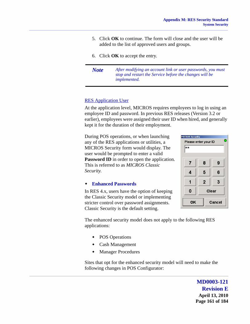
Appendix M: RES Security StandardSystem Security
5. Click OK to continue. The form will close and the user will be added to the list of approved users and groups.
6. Click OK to accept the entry.
RES Application UserAt the application level, MICROS requires employees to log in using an employee ID and password. In previous RES releases (Version 3.2 or earlier), employees were assigned their user ID when hired, and generally kept it for the duration of their employment.
During POS operations, or when launching any of the RES applications or utilities, a MICROS Security form would display. The user would be prompted to enter a valid Password ID in order to open the application. This is referred to as MICROS Classic Security.
Enhanced PasswordsIn RES 4.x, users have the option of keeping the Classic Security model or implementing stricter control over password assignments. Classic Security is the default setting.
The enhanced security model does not apply to the following RES applications:
POS OperationsCash ManagementManager Procedures
Sites that opt for the enhanced security model will need to make the following changes in POS Configurator:
Note After modifying an account link or user passwords, you must stop and restart the Service before the changes will be implemented.
MD0003-121Revision E
April 13, 2010Page 161 of 184

Appendix M: RES Security StandardSystem Security
Disable the Use Micros Classic security option (System | Restaurant | Security).
Complete the Enhanced Password Security section to control the way passwords are created, validated, and maintained in the alternate system.
Assign valid User IDs and Passwords (Employee Setup | Security) to all active employees.
To differentiate from Classic Security, a second set of options was added for this purpose (see following image). Only one set is valid at a time. Rules for creating and maintaining passwords (length, duration, etc.) is only applicable in the Enhanced Security model.
EnhancedSecurityPasswords
Classic UserSecurityPasswords
Caution! Before closing POS Configurator, be sure to set the passwords for at least one administrative-level employee. Once this application is closed, users will not be able to sign onto any application without a valid User ID and Password.
MD0003-121Revision EApril 13, 2010Page 162 of 184
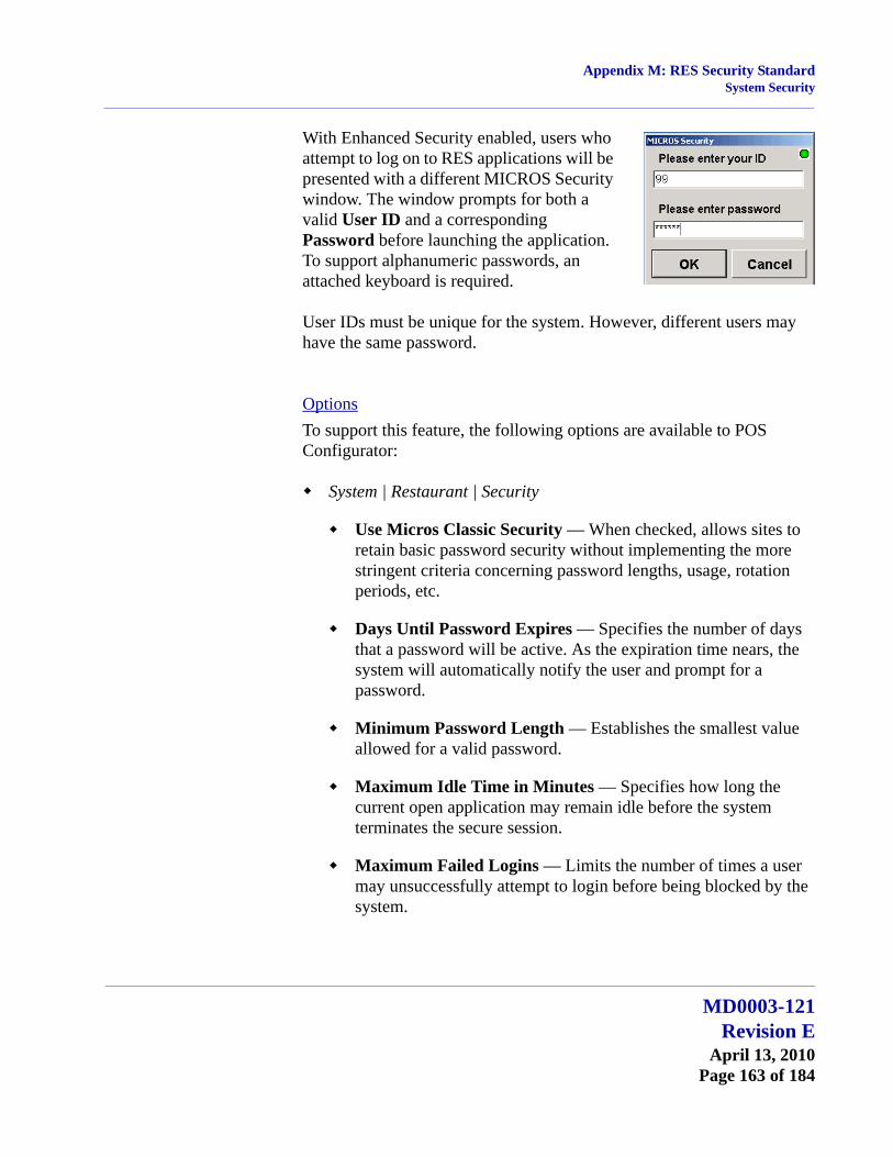
Appendix M: RES Security StandardSystem Security
With Enhanced Security enabled, users who attempt to log on to RES applications will be presented with a different MICROS Security window. The window prompts for both a valid User ID and a corresponding Password before launching the application. To support alphanumeric passwords, an attached keyboard is required.
User IDs must be unique for the system. However, different users may have the same password.
OptionsTo support this feature, the following options are available to POS Configurator:
System | Restaurant | Security
Use Micros Classic Security — When checked, allows sites to retain basic password security without implementing the more stringent criteria concerning password lengths, usage, rotation periods, etc.
Days Until Password Expires — Specifies the number of days that a password will be active. As the expiration time nears, the system will automatically notify the user and prompt for a password.
Minimum Password Length — Establishes the smallest value allowed for a valid password.
Maximum Idle Time in Minutes — Specifies how long the current open application may remain idle before the system terminates the secure session.
Maximum Failed Logins — Limits the number of times a user may unsuccessfully attempt to login before being blocked by the system.
MD0003-121Revision E
April 13, 2010Page 163 of 184
Appendix M: RES Security StandardSystem Security
Require AlphaNumeric Passwords — When checked, requires valid passwords to include a combination of letters and numbers. This option is disabled if the site is using Micros classic security.
Password Repeat Interval — Specifies how many times the password entry must be changed before the current one can be repeated.
AutoSeqServ Logon Options
The following options only need to be changed if additional system access is required to run certain autosequences, such as network report printing and external programs that access network shares.
Local System account — Directs the current service to log on using the local account and local permissions. This is the default option. Clear this option to have the service log on using a separate account, as defined under the This account option.
Allow service to interact with desktop — When checked, provides a user interface on the desktop that can be accessed by whomever is logged on when the service is started. This option is only enabled when the service is running as a Local System account.
This account — Directs the service to log on using a specifically defined user account. This allows the user to have access to resources such as files and folders protected by the Windows operating system. This option must be enabled when using enhanced security access.
In addition to selecting the radio button, programmers must provide a User Name for the account and enter the Password (and Confirm Password). Refer to the Administrative Services User section (beginning or page 159) for instructions on configuring this user.
Note Enabling this option requires a reboot of the server.
MD0003-121Revision EApril 13, 2010Page 164 of 184

Appendix M: RES Security StandardSystem Security
Employees | Employees | Security — These options are only relevant if Micros Classic Security is disabled.
User ID — Specifies an identifier for the employee log-on. Up to 20 characters may be entered.
User Password — Specifies the entry needed to authenticate the User ID and permit access to the system. Password length and composition (text, numbers, or alphanumeric combination) are defined under Enhanced Password security on the System | Restaurant | Security form.
Confirm User Password — Duplicates the User Password for confirmation of entry.
User must change password at first logon — When checked, requires the user to immediately change his/her password at the next logon. Although intended for employees, this option can also be used to reset an employee password after the account was disabled.
User Account Disabled — When checked, prevents a user from logging onto the system, even with a valid User ID and Password. This option may be triggered automatically if the employee exceeded the Minimum Failed Logins (System | Restaurant | Security) required to access the system.
MICROS Security LogIn order to comply with financial agencies (e.g., VISA, CISP, AIS, PCI) that require an audit trail (or log) of all activities that involve access to sensitive data, MICROS maintains a Security Log. The entries posted to the log must be reviewed on a regular basis for irregularities and an audit trail history must be maintained. Should a problem arise with an account, the audit trail would allow investigators to assess whether or not security has been breached, and if so, determine how to prevent such actions in the future.
The Security Log is installed as a custom plug-in to the Microsoft® Event Viewer along with the rest of the RES 4.x software. The default setting is enabled.
MD0003-121Revision E
April 13, 2010Page 165 of 184
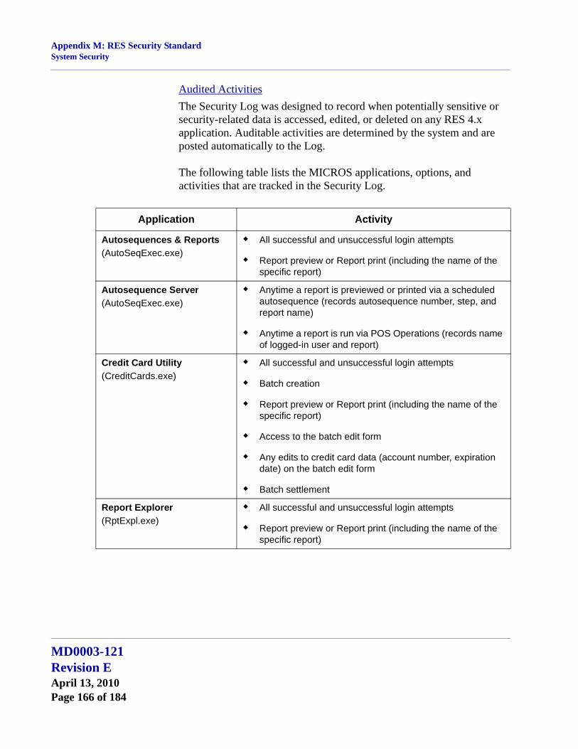
Appendix M: RES Security StandardSystem Security
Audited ActivitiesThe Security Log was designed to record when potentially sensitive or security-related data is accessed, edited, or deleted on any RES 4.x application. Auditable activities are determined by the system and are posted automatically to the Log.
The following table lists the MICROS applications, options, and activities that are tracked in the Security Log.
Application Activity
Autosequences & Reports(AutoSeqExec.exe)
All successful and unsuccessful login attempts
Report preview or Report print (including the name of the specific report)
Autosequence Server(AutoSeqExec.exe)
Anytime a report is previewed or printed via a scheduled autosequence (records autosequence number, step, and report name)
Anytime a report is run via POS Operations (records name of logged-in user and report)
Credit Card Utility(CreditCards.exe)
All successful and unsuccessful login attempts
Batch creation
Report preview or Report print (including the name of the specific report)
Access to the batch edit form
Any edits to credit card data (account number, expiration date) on the batch edit form
Batch settlement
Report Explorer(RptExpl.exe)
All successful and unsuccessful login attempts
Report preview or Report print (including the name of the specific report)
MD0003-121Revision EApril 13, 2010Page 166 of 184
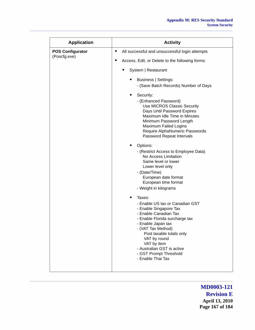
Appendix M: RES Security StandardSystem Security
POS Configurator (Poscfg.exe)
All successful and unsuccessful login attempts
Access, Edit, or Delete to the following forms:
System | Restaurant
Business | Settings:- (Save Batch Records) Number of Days
Security:- (Enhanced Password) Use MICROS Classic Security Days Until Password Expires Maximum Idle Time in Minutes Minimum Password Length Maximum Failed Logins Require AlphaNumeric Passwords Password Repeat Intervals
Options: - (Restrict Access to Employee Data) No Access Limitation Same level or lower Lower level only- (Date/Time) European date format European time format- Weight in kilograms
Taxes:- Enable US tax or Canadian GST- Enable Singapore Tax- Enable Canadian Tax- Enable Florida surcharge tax- Enable Japan tax- (VAT Tax Method) Post taxable totals only VAT by round VAT by item- Australian GST is active- GST Prompt Threshold- Enable Thai Tax
Application Activity
MD0003-121Revision E
April 13, 2010Page 167 of 184
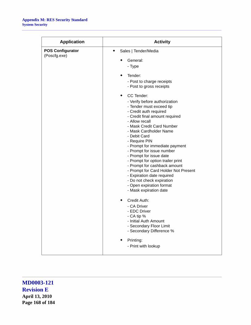
Appendix M: RES Security StandardSystem Security
POS Configurator (Poscfg.exe)
Sales | Tender/Media
General:- Type
Tender:- Post to charge receipts- Post to gross receipts
CC Tender:- Verify before authorization- Tender must exceed tip- Credit auth required- Credit final amount required- Allow recall- Mask Credit Card Number- Mask Cardholder Name- Debit Card- Require PIN- Prompt for immediate payment- Prompt for issue number- Prompt for issue date- Prompt for option trailer print- Prompt for cashback amount- Prompt for Card Holder Not Present- Expiration date required- Do not check expiration- Open expiration format- Mask expiration date
Credit Auth:- CA Driver- EDC Driver- CA tip %- Initial Auth Amount- Secondary Floor Limit- Secondary Difference %
Printing:- Print with lookup
Application Activity
MD0003-121Revision EApril 13, 2010Page 168 of 184

Appendix M: RES Security StandardSystem Security
POS Configurator (Poscfg.exe)
Revenue Center | RVC Credit Cards
General:- Suppress amount on initial authorization- Suppress linefeeds after voucher- Authorize below CA floor message- Allow 20 reference characters- Confirm customer signature- Disable charged tip- Do not add estimated tips to CC authorization- Disable prompt for Card Holder Not Present- (CA Status) Enable CA status display Display for entire RVC
Headers:- CC Voucher Header
Trailers:- Customer CC Trailer- Customer Initial Auth Trailer- Customer Optional 2nd Trailer- Customer Cashback Trailer- Merchant CC Trailer- Merchant Initial Auth Trailer- Merchant Optional 2nd Trailer- Merchant Cashback Trailer
Floor Limits:- Enable secondary floor limit %- Enable secondary floor limit amount
Printing:- Print two vouchers- Print voucher in background- Print initial credit authorization voucher- Print voucher after secondary authorization- Do not print customer name on voucher- Show REPRINT on voucher- Print TOTAL on voucher
Application Activity
MD0003-121Revision E
April 13, 2010Page 169 of 184
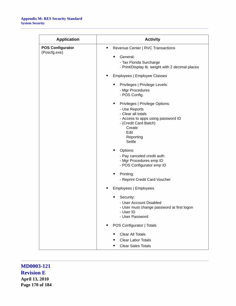
Appendix M: RES Security StandardSystem Security
POS Configurator (Poscfg.exe)
Revenue Center | RVC Transactions
General:- Tax Florida Surcharge- Print/Display lb. weight with 2 decimal places
Employees | Employee Classes
Privileges | Privilege Levels:- Mgr Procedures- POS Config.
Privileges | Privilege Options:- Use Reports- Clear all totals- Access to apps using password ID- (Credit Card Batch) Create Edit Reporting Settle
Options:- Pay canceled credit auth- Mgr Procedures emp ID- POS Configurator emp ID
Printing:- Reprint Credit Card Voucher
Employees | Employees
Security:- User Account Disabled- User must change password at first logon- User ID- User Password
POS Configurator | Totals
Clear All TotalsClear Labor TotalsClear Sales Totals
Application Activity
MD0003-121Revision EApril 13, 2010Page 170 of 184

Appendix M: RES Security StandardSystem Security
GSS Backoffice(GSS.exe)
All successful and unsuccessful login attempts
Access to all forms (edits not recorded)
Export Utility(ExportUtility.exe)
All successful and unsuccessful login attempts
All queries run
Transaction Analyzer(Analyzer.exe)
All successful and unsuccessful login attempts
Whenever a query is created
Whenever a query is run
Whenever a query is saved
Records all query details
Database Manager(DM.exe)
All successful and unsuccessful login attempts
Records all DM functions, whether implemented through the user interface (GUI) or from the Command Line.
EM(Mecu.exe)
All successful and unsuccessful login attempts
EM(EMStoreTotalsSynch.exe)
All successful and unsuccessful login attempts
EM(Store Employee Import Utility)
All successful and unsuccessful login attempts
EM(UCTconfig.exe)
All successful and unsuccessful login attempt
EM (MIPriceWiz.exe)
All successful and unsuccessful login attempts
Forecast Setup(ForecastSetup.exe)
All successful and unsuccessful login attempts
Forecasting(Forecasting.exe)
All successful and unsuccessful login attempts
Human Resources(HumanResources.exe)
All successful and unsuccessful login attempts
Labor Management(LM.exe)
All successful and unsuccessful login attempts
Application Activity
MD0003-121Revision E
April 13, 2010Page 171 of 184
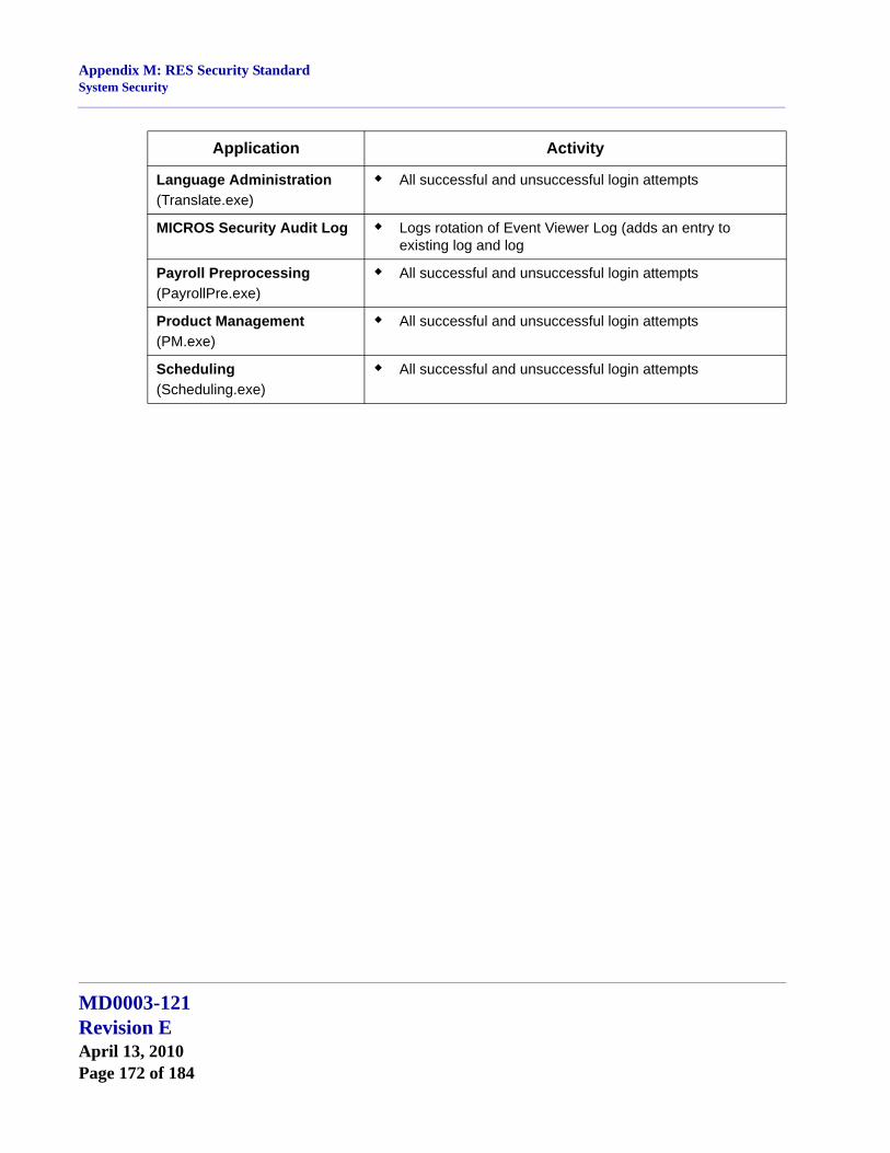
Appendix M: RES Security StandardSystem Security
Language Administration(Translate.exe)
All successful and unsuccessful login attempts
MICROS Security Audit Log Logs rotation of Event Viewer Log (adds an entry to existing log and log
Payroll Preprocessing(PayrollPre.exe)
All successful and unsuccessful login attempts
Product Management(PM.exe)
All successful and unsuccessful login attempts
Scheduling(Scheduling.exe)
All successful and unsuccessful login attempts
Application Activity
MD0003-121Revision EApril 13, 2010Page 172 of 184
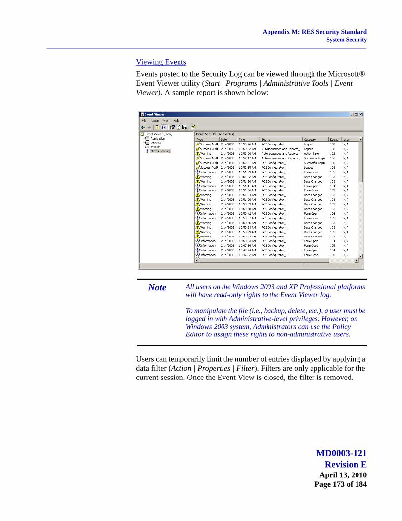
Appendix M: RES Security StandardSystem Security
Viewing EventsEvents posted to the Security Log can be viewed through the Microsoft® Event Viewer utility (Start | Programs | Administrative Tools | Event Viewer). A sample report is shown below:
Users can temporarily limit the number of entries displayed by applying a data filter (Action | Properties | Filter). Filters are only applicable for the current session. Once the Event View is closed, the filter is removed.
Note All users on the Windows 2003 and XP Professional platforms will have read-only rights to the Event Viewer log.
To manipulate the file (i.e., backup, delete, etc.), a user must be logged in with Administrative-level privileges. However, on Windows 2003 system, Administrators can use the Policy Editor to assign these rights to non-administrative users.
MD0003-121Revision E
April 13, 2010Page 173 of 184

Appendix M: RES Security StandardSystem Security
Viewing DetailsEvent details can be viewed by double-clicking the item and opening the individual record. For each event logged, the system provides these details:
Date — Date action occurred.
Time — Time action occurred.
Source — RES 4.x application where the activity occurred.
Type/Category — Event label and descriptor. The options are:
Event — ID number.
User — Name of the remote operating system user, if any.
Computer — Computer name where event occurred.
Description — Details of the event, including the user name, forms accessed (if any), and any changes made to the actual options.
Type Category
Success Audit Successful LoginLogout
Failure Audit Failed Login
Warning Data Changed
Information Form openForm closeAction Taken
MD0003-121Revision EApril 13, 2010Page 174 of 184
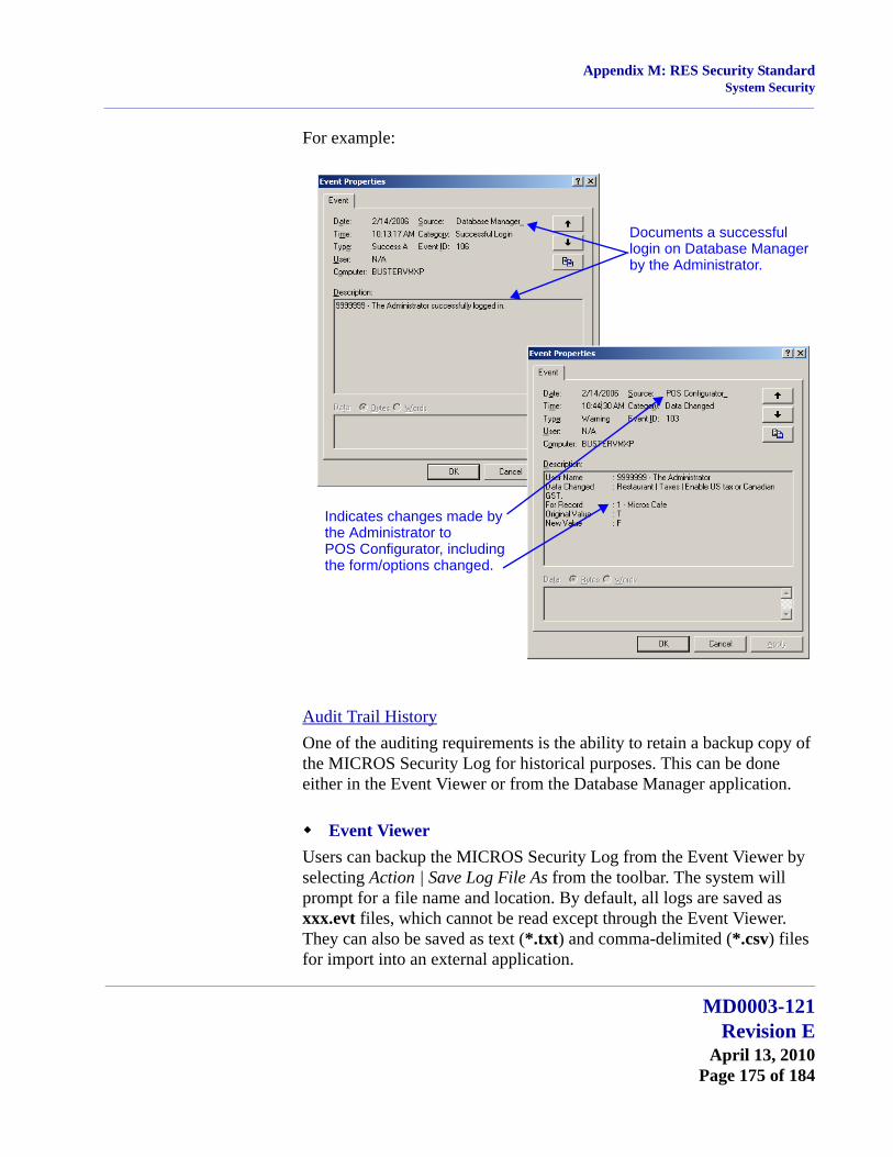
Appendix M: RES Security StandardSystem Security
For example:
Audit Trail HistoryOne of the auditing requirements is the ability to retain a backup copy of the MICROS Security Log for historical purposes. This can be done either in the Event Viewer or from the Database Manager application.
Event ViewerUsers can backup the MICROS Security Log from the Event Viewer by selecting Action | Save Log File As from the toolbar. The system will prompt for a file name and location. By default, all logs are saved as xxx.evt files, which cannot be read except through the Event Viewer. They can also be saved as text (*.txt) and comma-delimited (*.csv) files for import into an external application.
Documents a successfullogin on Database Managerby the Administrator.
Indicates changes made bythe Administrator to POS Configurator, includingthe form/options changed.
MD0003-121Revision E
April 13, 2010Page 175 of 184

Appendix M: RES Security StandardSystem Security
Database ManagerThe Database Manager also includes options for backing up the MICROS Security Log, but these are limited. Users can only enter a filename and specify where to store the backup. The default filename is Microssecuritylogyyyymmdd.evt.
Risk ManagementMaintaining a secure network requires more than encryption and passwords. To ensure data privacy, users must assume some responsibility for establishing a secure work environment and for implementing policies and procedures that protect their system as well as their customer’s personal information.
This section includes recommendations for risk management in a highly computerized environment. In addition to standard practices, it describes a number of programming options and processes that, while not explicitly prevented, are strongly discouraged as they may cause problems with and/or compromise the system.
Security StandardsIn a secure environment, users are responsible for:
Securing the Network — This includes installing and maintaining a firewall, monitoring network access, and regularly performing diagnostics to test the integrity of the security system.
Changing Passwords — Once a user is added, it is up to the site to enforce rules on password rotation. Regularly changing passwords (e.g., every 60 or 90 days) reduces the probability that they will be obtained and used by someone outside the system. Similarly, when installing third-party applications, users are responsible for securing the interface by changing default settings and passwords.
Hiring Policies — A system is only as secure as the people who operate it. Sites have sole responsibility for their hiring practices, assignment of user IDs, and granting access to the network, servers, workstations, key cards, or other physical devices that might provide access to the data.
MD0003-121Revision EApril 13, 2010Page 176 of 184

Appendix M: RES Security StandardSystem Security
Limitations and RecommendationsThe following items represent known issues that will impact the secure database:
Sybase Updates — All RES products are designed to work with the specific version of Sybase 9 software that is included with the current installation. Users are strongly advised to avoid downloading Sybase updates (either from the Sybase website or by using the automatic upload option from the DBISQL Help option) and applying them to the system.
Fast User Switching — This option allows 2 users to log onto the computer simultaneously, and to switch between active users without having the current user log off first. RES 4.x does not support this option on the Windows XP platform. If enabled, it may cause some applications and/or processes to fail.
To disable, open the Windows Control Panel and select User Accounts | Change the way users log on or off. When the form displays, clear the option Use Fast User Switching.
SIM Scripts — Sites using SIM scripts to read track data from a magnetic stripe card should be aware that the FULL track data will be exposed by SIM. For security reasons, users should evaluate any SIM script that involves credit card track data to assess whether or not the script should be used in RES 4.x.
Enhanced Security — When using enhanced security, user passwords are not stored in the database in plain text. They are stored with one-way encryption (hashed). Third parties that wished to add employees to the MICROS database (micros.emp_def) must insert the employee record without the user password.
These users will have access to POS Operations, Manager Procedures, and Cash Management through their Password ID, but will not have access to other RES applications until a privileged user opens POS Configurator | Employees | Employees | Security and assigns a User Password.
MD0003-121Revision E
April 13, 2010Page 177 of 184

Appendix M: RES Security StandardElectronic Payments
Configuration This section is intended to provide a guide for configuring the discussed security features.
Electronic Payments Electronic Payments are another critical area of the POS environment that is often targeted by attacks. The user can protect their system in the following ways:
Read the Payment Application Best Practices documentation, and follow the steps to secure electronic payments in the database.
Install the Transaction Vault Credit Card Driver.
Payment Application Best PracticesWhen customers offer their bankcard at the point of sale, over the Internet, on the phone, or through the mail, they want assurance that their account information is safe. That’s why Visa USA has instituted the Payment Application Best Practices (PABP) program. The program is intended to protect Visa cardholder data—wherever it resides—ensuring that members, merchants, and service providers maintain the highest information security standard.
Payment Application Best Practices (PABP) is a quick reference guide that provides information concerning MICROS’s adherence to the Visa PABP Data Security Standard. This documentation contains a series of steps required by Visa. Please consult the Payment Application Best Practices Data Security Standard Adherence Documentation for the appropriate version of RES and implement the suggested practices.
Transaction Vault Credit Card Driver Traditionally, cardholder data (card number, expiration date, and the cardholder name) is stored by the RES system until it is purged from the system, typically within 90-180 days after settlement. In this environment, it is possible for a site to be the victim of a malicious attack, potentially compromising credit card data.
MD0003-121Revision EApril 13, 2010Page 178 of 184
Appendix M: RES Security StandardElectronic Payments
To provide the best possible protection against these threats, MICROS recommends that the site implement the TransactionVault Credit Card Driver solution. Transaction Vault stores all sensitive data in the TransactionVault, a hosted database at Merchant Link, instead of in the merchant’s local RES database. Merchant Link’s TransactionVault coupled with MICROS 3700 secures data for the customer, minimizing the potential for security breaches.
The purpose of the TransactionVault feature is to remove sensitive credit card information from the RES data store. This is done by using Merchant Link to provide the card storage at their data center. In exchange, Merchant Link provides a TransactionVault key that replaces all cardholder information at the customer site. The key utilizes leading edge encryption technology, which helps to ensure that only TransactionVault can match the key to access the cardholder information.
For additional information about TransactionVault see the Transaction Vault Credit Card ReadMe First, MD0003-121.
PCI Compliance Verified at System StartupThe system will now verify that the site is compliant with the PCI Credit Card Data Security Standard upon starting POS Operations. This will occur if the following conditions are met:
The site is not in demo mode, and
At least 1 tender is linked to a non-demo driver.
If the site is not compliant, POS Operations will not start and an error message will appear. The text in the log will indicate the reason why the site was deemed to be non-PCI compliant. All error messages and steps to correct them are listed in the Error Messages section on page 61.
The system uses the following criteria to determine a site’s PCI-compliance:
DBA database password is not set to the default.
MICROS database password is not set to the default.
MD0003-121Revision E
April 13, 2010Page 179 of 184

Appendix M: RES Security StandardElectronic Payments
Database file encryption passphrase is not set to the default.
Sensitive data passphrase is not set to the default.
Complex Security enabled at the site.
Security is configured as specified in the RES Version 4.3 Hotfix 1 or Higher Payment Application-Data Security Standard (PA-DSS) Implementation Guide, MD0003-117. These settings include:
Days Until Expiration (POS Configurator | System | Restaurant | Security). This field specifies the number of days that a password may remain active before it must be changed. This value cannot be greater than 90 days.
Minimum Password Length (POS Configurator | System | Restaurant | Security). Enter the minimum number of characters required for the password length. This field must be set to a minimum of 7.
Password Repeat Interval (POS Configurator | System | Restaurant | Security). Enter the number of different passwords that must be used before an old password can be repeated. This option must be set to a minimum of 4.
Require Alphanumeric Passwords (POS Configurator | System | Restaurant | Security). Select this option to require passwords to contain letters and numbers. This option must be enabled.
Maximum Allowed Failed Logins (POS Configurator | System | Restaurant | Security). Enter the number of failed logins that may occur before locking the user out of his/her account. This value cannot be greater than 6.
Maximum Idle Time (POS Configurator | System | Restaurant | Security). Enter the number of minutes an administrative application will remain idle before the application will undo any saved changes and exit, requiring the user to login again. This setting cannot be more than 15 minutes.
MD0003-121Revision EApril 13, 2010Page 180 of 184
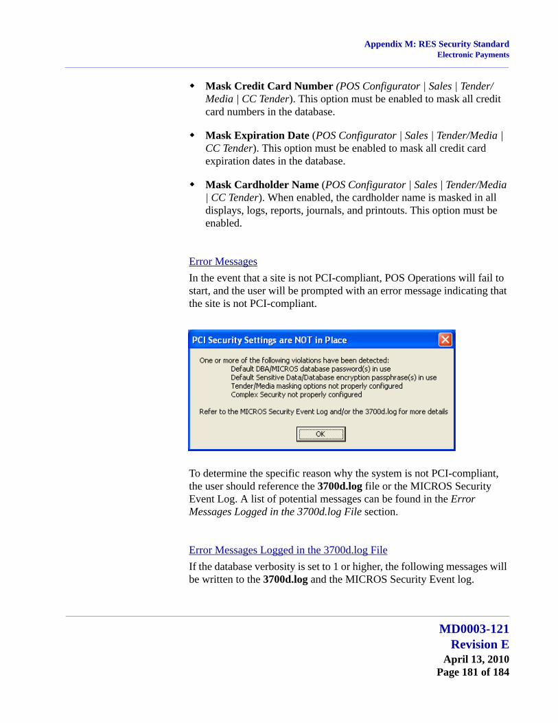
Appendix M: RES Security StandardElectronic Payments
Mask Credit Card Number (POS Configurator | Sales | Tender/Media | CC Tender). This option must be enabled to mask all credit card numbers in the database.
Mask Expiration Date (POS Configurator | Sales | Tender/Media | CC Tender). This option must be enabled to mask all credit card expiration dates in the database.
Mask Cardholder Name (POS Configurator | Sales | Tender/Media | CC Tender). When enabled, the cardholder name is masked in all displays, logs, reports, journals, and printouts. This option must be enabled.
Error MessagesIn the event that a site is not PCI-compliant, POS Operations will fail to start, and the user will be prompted with an error message indicating that the site is not PCI-compliant.
To determine the specific reason why the system is not PCI-compliant, the user should reference the 3700d.log file or the MICROS Security Event Log. A list of potential messages can be found in the Error Messages Logged in the 3700d.log File section.
Error Messages Logged in the 3700d.log FileIf the database verbosity is set to 1 or higher, the following messages will be written to the 3700d.log and the MICROS Security Event log.
MD0003-121Revision E
April 13, 2010Page 181 of 184

Appendix M: RES Security StandardElectronic Payments
If Demo Mode is in use, or credit cards are not used, then the following messages will be written to the log, and POS Operations will start successfully.
DbCheckPCICompliance: system in demo mode, skipping PCI verification
DbCheckPCICompliance: CA/EDC not in use, skipping PCI verification
If the database is configured for production credit cards, and the database is not PCI-compliant, then POS Operations will not start and the following messages will appear in the log. These messages will appear regardless of the verbosity setting.
WARNING! Before Changing the Data Key or the Database Key, all credit card transactions should be batched and settled. The server and clients must be rebooted after changing the key.
Error msg - PCI Security Error: Sensitive data passphrase set to default. The sensitive data passphrase must be changed from the default settings. Go to Database Manager | Encryption Keys and select the Data key and press the [Change Encryption Keys] button. The system will automatically select a key.
Error msg - PCI Security Error: Database passphrase set to default. This message indicates that the default passphrase must be changed. Go to Database Manager | Encryption Keys and select the Database key and press the [Change Encryption Keys] button. The system will automatically select a key.
Error msg - PCI Security Error: DBA password set to default. This message indicates that the DBA password should be changed from the default settings. This password must be complex, containing a minimum of 7 characters with both alpha and numeric characters.
Error msg - PCI Security Error: MICROS password set to default. This message indicates that the MICROS password should be changed from the default settings. This password must be complex, containing a minimum of 7 characters with both alpha and numeric characters.
MD0003-121Revision EApril 13, 2010Page 182 of 184

Appendix M: RES Security StandardElectronic Payments
Error msg - PCI Security Error: One or more tenders not set to mark sensitive data. One or more of the option bits to mark card number, expiration date, and customer name must be enabled for any tender linked to a production credit card driver in POS Configurator.
Error msg - PCI Security Error: Complex security not enabled (POScfg | System | Restaurant | Security, Disable “Use Micros Class Security.” Enhanced security must be enabled in POS Configurator, follow the path listed in the error message to make this change.
Error msg - PCI Security Error: Password expiration setting exceeds maximum allowed (not greater than 90). The Days Until Expiration field contains a value that exceeds 90 days.
Error msg - PCI Security Error: Minimum password length less than minimum allowed (at least 7). The Minimum Password Length field must be set to a value of 7 or greater.
Error msg - PCI Security Error: Password repeat interval less than minimum (at least 4). The Password Repeat Interval field should be set to a value of 4 or greater.
Error msg - PCI Security Error: Alphanumeric passwords not required (must be enabled). The Require Alphanumeric Passwords field must be enabled.
Error msg - PCI Security Error: Maximum failed login attempts exceeds maximum allowed (not greater than 6). The Maximum Allowed Failed Logins field must be set to a value of 6 or lower.
Error msg - PCI Security Error: Maximum idle time exceeds maximum allowed (no more than 15 minutes). The Maximum idle time field must be set to a value of 15 minutes or less.
PCI Compliance and Table Pay ServicePlease keep the following issues in mind after upgrading a system running Table Pay Service (TPS):
MD0003-121Revision E
April 13, 2010Page 183 of 184
Appendix M: RES Security StandardElectronic Payments
If the system is not PCI-compliant at the time of upgrade, and is later updated to be compliant, then the user must restart TPS. If not, then the device running TPS will continue to indicate that it is “NOT PCI compliant,” even after the system is compliant.
To become PCI-compliant, sites must change the DBA and MICROS passwords from the Defaults. If TPS_Configuration.exe was set to connect to the DB using either the DBA or MICROS user, then the TPS device will be unable communicate until the defaults are changed.
If the system is not PCI-compliant, the TPS device will print a receipt saying “Not PCI Compliant”, however, it will not log the reason(s) why to either the Event viewer or 3700d.log.
MD0003-121Revision EApril 13, 2010Page 184 of 184