resources... · interim guidelines for the use of self-consolidating concrete in...
TRANSCRIPT
Interim Guidelines for the Use of Self-Consolidating Concrete in Precast/Prestressed Concrete Institute Member Plants
TR-6-03 Precast/Prestressed Concrete Institute Interim SCC Guidelines FAST Team Curtis Badman Sika Corporation, Inc. John Bareño Oldcastle Precast, Inc. Ken Baur High Concrete Structures Chris Boster Fabcon Inc. Clint Calvert Coreslab Structures Rodney Cunningham Boral Material Technologies Joe Daczko Master Builders/Degussa Diane Hughes W.R. Grace Corporation John Kaiser Spancrete Industries Gary Knight W.R. Grace Corporation Michael LaNier* BERGER/ABAM Engineers Inc. Christopher Leaton The Bluhm Company Don Logan Stresscon Corporation Edward Mansky W.R. Grace Corporation Ondrej Masek Sika Corporation, Inc. Richard Miller University of Cincinnati Frank Nadeau Unistress Corporation Greg Roache Master Builders/Degussa David Sprague Master Builders/Degussa Martin Vachon Axim Concrete Technologies, Inc. Michael Wade Boral Material Technologies, Inc. James Wamelink Axim Concrete Technologies, Inc. Don Yarbrough Ross Bryan Associates * Chairman April 2003 Precast/Prestressed Concrete Institute 209 West Jackson Boulevard Chicago, Illinois 60606-6938 Phone: 312/786-0300 E-mail: [email protected] www.pci.org
TR-6-03 Copyright © 2003
By Precast/Prestressed Concrete Institute
All rights reserved.
This book or any part thereof may not be reproduced in any form without the written permission of the Precast/Prestressed Concrete Institute.
First Edition, 2003 Second Printing, 2003
Third Printing, 2004
ISBN 0-937040-68-1
Printed in the United States of America
Every effort has been made to ensure the accuracy of the information presented in
this Manual. However, PCI cannot accept responsibility for errors, oversights, or
the misuse of the information contained herein. The user must recognize that no
manual or regulation can substitute for experience and sound judgment. This
publication is intended for use by personnel competent to evaluate the significance
and limitations of the information it contains, and accept responsibility for its proper
interpretation and application.

Interim Guidelines for the Use of Self-Consolidating D03016 Concrete in PCI Member Plants ii April 2003
TABLE OF CONTENTS Section Page Foreword ........................................................................................................................................... 1 Definitions ........................................................................................................................................ 3 Division 1 Introduction and Guidelines for SCC Applicability ............................................... 9 Division 2 Guidelines for Qualification of Constituent Materials for SCC .............................. 13 and Recommendations for Accomplishing a SCC Mix Design Division 3 Guidelines for the Production Qualification of SCC .............................................. 29 Division 4 Guidelines for Quality Control of Fresh SCC and Initiation of Curing .................. 53 Division 5 Guidelines for Quality Confirmation of Hardened SCC and Quality ..................... 63 Confirmation of Elements Fabricated from SCC Division 6 Guidelines for Forms, Transport, Placing, Finishing, and Curing .......................... 67 Division 7 Guidelines for Addressing Performance and Prescriptive Project Specifications .. 71 References and Standards ................................................................................................................. 77 Appendix 1 SCC Test Methods ………………………………………………………………... A1-1 Appendix 2 SCC Checklist …………………………………………………………………….. A2-1 Appendix 3 SCC Mix Design Examples ………………………………………………………. A3-1 Appendix 4 Sources for SCC Test Apparatus …………………………………………………. A4-1 Acknowledgments Many thanks to the contributors listed on the title page. All generously contributed their time and were supported by the resources of their respective companies. Thanks also to the management of BERGER/ABAM for agreeing to allow final formatting and editing by the BERGER/ABAM word processing staff.

Interim Guidelines for the Use of Self-Consolidating D03016 Concrete in PCI Member Plants 1 April 2003
FOREWORD These interim guidelines have been prepared in response to increasing use of and interest in Self-Consolidating Concrete (SCC) in the prestressed concrete industry throughout the United States. (Note: In current North American practice, the terms "Self-Compacting Concrete" and "Self-Consolidating Concrete" relate to the same material.) SCC is a highly workable concrete that can flow through densely reinforced or geometrically complex structural elements under its own weight and adequately fill voids without segregation or excessive bleeding without the need for vibration to consolidate it. The workability of SCC is higher than the highest class of workability associated with normal high-performance concrete typically used in precast/prestressed concrete fabrication plants. This workability can be characterized by the following properties.
Filling ability – (confined flowability) – The ability of SCC to flow under its own weight (without vibration) into and fill completely all spaces within intricate formwork, containing obstacles, such as reinforcement.
Passing ability – The ability of SCC to flow through openings approaching the size of the mix coarse
aggregate, such as the spaces between steel reinforcing bars, without segregation or aggregate blocking. (This property is of concern only in those applications that involve placement in complex shapes or sections with closely spaced reinforcing.)
Stability (segregation resistance) – The ability of SCC to remain homogeneous during transport,
placing, and after placement. A concrete mix is classified as SCC if the requirements for all three of the above characteristics are fulfilled. In instances where passing ability is not a concern, this parameter need not be addressed. SCC has properties that differ significantly from conventional high-performance concrete. Thus some auxiliary tools, such as new characterization and quality control tests and procedures that are adapted to the special properties of the material, are needed. It is recognized that currently (June 2002) there are groups within the American Concrete Institute (ACI), the American Society for Testing Materials (ASTM), and possibly other organizations in North America that are working on definitive consensus standards for this material. It is also noted that the finalization of standards from the traditional industry standards setting groups are at least several years away. Thus there is a need for these interim guidelines to assist the precast/prestressed concrete industry in moving forward to responsibly incorporate the use of SCC in the fabrication of precast products. It is expected that these interim guidelines will be superceded by industry consensus standards as they are published. The group that has been charged with the development of these interim guidelines includes representatives of admixture suppliers currently active in the provision of admixtures used in the production of SCC in the United States, precast concrete producer representatives that have direct experience in the development of SCC mixes and use of SCC in precast product manufacture, and representatives of industry consulting engineering firms. The guidelines address the use of SCC in Precast/Prestressed Concrete Institute (PCI) precast/prestressed concrete manufacturing plant settings and reference PCI plant quality manuals, MNL-116-99 Manual for Quality Control for Plants and Production of Structural Precast Concrete Products and MNL-117-96
Interim Guidelines for the Use of Self-Consolidating D03016 Concrete in PCI Member Plants 2 April 2003
Manual for Quality Control for Plants and Production of Architectural Precast Concrete Products. Construction site use of SCC is not addressed in these guidelines. The goal of this publication is to present the best available information on SCC as it applies to current North American practice. It is recognized that SCC practice is currently evolving as experience with the material is gained in differing circumstances and for different purposes. These guidelines have been additionally reviewed and commented on an expedited basis by selected members of the PCI Technical Activities Committee and the PCI High-Performance Concrete Committee.

Interim Guidelines for the Use of Self-Consolidating D03016 Concrete in PCI Member Plants 3 April 2003
DEFINITIONS The following are definitions of terms as they apply to the subject of SCC. Admixture – A material, other than water, aggregates, hydraulic cement, and fiber reinforcement, used as
an ingredient in concrete or mortar, and added to the batch immediately before or during its mixing to modify the properties of the fresh or hardened concrete.
Aggregate aspect ratio – The ratio of length to width of individual pieces of coarse aggregate. This ratio
sometimes affects the characteristics of SCC. Aggregate blocking – The situation in which coarse aggregate particles jam between reinforcing steel
bars or other obstacles within the form and prevent free flow of SCC. Air migration – An undesirable condition in which the entrained air in the fresh concrete migrates to
form areas of higher than designed entrained air content and corresponding areas of lower than designed entrained air content.
Architectural concrete – Concrete mixes developed primarily for the visual appearance of the concrete
surface. Binder – The combined cement and hydraulic powder addition in a SCC mix. Cementing materials,
either hydrated cements or lime, and reactive siliceous materials – used to form the matrix in SCC. Bingham fluid – A fluid characterized by a non-null yield stress and a constant viscosity regardless of
flow rate. Bleed water – The water that rises to the surface of SCC subsequent to the placing of the concrete. The
autogeneous flow of mixing water within, or its emergence from, newly placed concrete or mortar; caused by the settlement of solid materials within the concrete mass.
Bleeding test (French) – See Appendix 1 – A test used to determine the tendency of a concrete mix to
bleed. The test evaluates both the speed of bleeding and the total quantity of bleed water from a specimen of known volume.
Bleeding test (ASTM C 232) – The standard test for determining the relative quantity of mixing water
that will bleed from a sample of freshly mixed concrete. For use with SCC, the ASTM standard test is used with the exception that the sample is not rodded or vibrated to consolidate it.
Blocking – The condition in which pieces of coarse aggregate combine to form elements large enough to
obstruct the flow of the fresh concrete between the reinforcing steel or other obstructions in the concrete formwork. This property is of increased importance in SCC because of the absence of vibration energy to dislodge these blockages.
Blocking resistance – See passing ability. Caisson test – See filling vessel test. Cohesiveness – The tendency of the SCC constituent materials to stick together, resulting in resistance to
segregation, settlement, and bleeding.

Interim Guidelines for the Use of Self-Consolidating D03016 Concrete in PCI Member Plants 4 April 2003
Compactability – The ability of the SCC mix to form a dense compact mass without the requirement for input of external energy (vibration). The degree to which SCC mixtures will be densified and de-aired of entrapped air yielding few internal voids.
Confined flowability – The ability of a fresh concrete to flow in a form characterized by a low ratio of
horizontal form surface to total form surface. Consolidation – The process of inducing a closer arrangement of the solid particles in freshly mixed
concrete or mortar, during placement by the reduction of voids; usually in non-SCC by vibration, centrifugation, rodding, tamping, or some combination of these actions. In SCC, consolidation is by gravity flow of the material.
Dynamic segregation resistance – See dynamic stability. Dynamic stability – That characteristic of a fresh SCC mixture that ensures uniform distribution of all
solid particles and air voids as the SCC is being transported and placed. Filling ability – The ability of SCC to flow under its own weight (without vibration) into and fill
completely all spaces within intricate formwork, containing obstacles, such as reinforcement. Fines – See powder. Finishability – Ability to achieve the desired finish on that portion of the precast element that must be
finished (not a formed surface). Flowability – The ability of a fresh concrete to flow in a confined or unconfined form of any shape,
reinforced or not, under gravity and/or external forces, assuming the shape of its container. Flow separation resistance – The ability to resist segregation, formation of a mortar halo, or aggregate
stacking in the slump flow test, during transport or during placement. Fluidity – A property of fresh concrete indicating the ease of flowing under gravity effects. When
regarded as a Bingham fluid, fluidity is evaluated by the concrete yield stress and viscosity. Fly ash – A finely divided residue with pozzolanic properties that results from the combustion of ground
or powdered coal and that is transported by flue gasses. Due to its spherical shape and fineness, it can improve the rheology of SCC.
Ground (granulated) blast furnace slag (GGBFS) – A fine granular, mostly latent hydraulic binding
material that can be added to SCC to modify the rheological properties of the material. High-fluidity concrete – Concrete that flows with very little external energy input. High-range water reducing agent (HRWRA) – A water-reducing admixture capable of producing large
water reduction (>12 percent) or great flowability of a concrete mix without causing undue set retardation or excessive entrainment of air.
Initial set – The point at which the concrete mixture reaches a strength of 500 psi (3.45 MPa). Also see
preset time. Jamming – See blocking.

Interim Guidelines for the Use of Self-Consolidating D03016 Concrete in PCI Member Plants 5 April 2003
J-Ring test – Test used to determine the passing ability of SCC, or the degree to which the passage of concrete through the bars of the J-ring apparatus is restricted. See Appendix 1.
K-test – A test of filling ability using a box shaped like the bottom half of a concrete I girder, with a
series of obstacles simulating reinforcing bars or prestressing strand. Side of box is Plexiglas to allow visual assessment of filling ability.
L-Box test – A test used to test the horizontal and confined flowability of SCC and/or to check that the
placement of SCC will not be compromised by unacceptable segregation and jamming or blocking of aggregates. See Appendix 1.
Metakaolin – Mineral admixture sometimes used to increase powder content of concrete mixes. Mixture robustness – The characteristic of a mix that encompasses its tolerance to variations in
constituent characteristics and quantities, as well as its tolerance to the effects of transportation and placement activities.
Moisture control of aggregates – Similar to that for normal high-performance concrete but required to
be done more precisely and more frequently in SCC mixes that are water content sensitive. Mortar fraction – The volume percentage of all materials in the mixture (cementitious materials,
aggregate, water, and air) that pass the #8 (2.36 mm) sieve. Mortar Halo – A concentration of mortar that can form at the perimeter of the slump flow patty. The
width of this halo is one of the parameters evaluated in the visual stability index (VSI) test used to judge the stability of plastic SCC mixes.
Orimet test – A test for assessment of highly workable, flowing concrete mixes. See Appendix 1. Orimet with J-Ring test – A test combining these two test methods to assess flow and passing ability of
a concrete mix. See Appendix 1. Passing ability – The ability of SCC to flow through openings approaching the size of the mix coarse
aggregate, such as the spaces between steel reinforcing bars without segregation or aggregate blocking.
Paste – The fraction of the SCC mix comprising powder plus water and air. Placeability – The ability to place the SCC mix in the time span associated with the typical production
mixing, transport, and placement such that the material remains homogeneous while exhibiting all of the required SCC fresh concrete properties.
Plastic viscosity – Condition of freshly mixed concrete such that deformation will be sustained
continuously in any direction without rupture; (OR) the measurement of a material’s resistance to increase in its rate of flow with increasing application of forcing energy.
Powder – Material of particle size passing the No. 100 sieve (0.15 mm).
Interim Guidelines for the Use of Self-Consolidating D03016 Concrete in PCI Member Plants 6 April 2003
Powder additions – Finely divided inorganic material used in SCC in order to improve certain properties or to achieve special properties. These guidelines refer to two types of inorganic powder additions: 1) nearly inert powder additions and 2) pozzolanic or latent hydraulic powder additions.
Powder-type SCC – SCC mixes that rely extensively for meeting SCC performance requirements on the
amount and character of the fines and powders included in the mix. Preset time – The time after mixing required to reach a degree of stiffening of concrete equal to a
strength of 500 psi (3.45 MPa) as measured by penetration resistance test or other means. Also see initial set time.
Pumpability – The ability of an SCC mix to be pumped without significant degradation of its fresh SCC
properties. Rheological properties – Properties dealing with the deformation and flow of the fluid fresh SCC
mixture. Rheological responsibility – Responsibility for the behavior of the plastic fresh SCC as it is handled and
placed in the forms. While mix performance properties are the responsibility of the producer, specialist SCC technologists play a increased role in the refinement of production SCC mixes.
Rheometer – A device used to determine the yield stress properties of fresh SCC. Screen stability test – Test method used to assess the segregation resistance (stability) of an SCC
mixture. See Appendix 1. Sedimentation – See settlement. Segregation – The differential concentration of the constituents of mixed concrete, coarse aggregate, and
the like, resulting in nonuniform proportion in the mass; (OR) a separation of the components of fresh concrete resulting in a nonuniform mix. In SCC, segregation may occur during transport, movement of the SCC within the forms, or after placement.
Segregation resistance (stability) – The ability of SCC to remain homogeneous in composition during
transport, placement, and after placement without constituents separating from the mass. Self-consolidating concrete (SCC) (also self-compacting concrete) – A highly workable concrete that
can flow through densely reinforced or complex structural elements under its own weight and adequately fill voids without segregation or excessive bleeding without the need for vibration.
Self-leveling concrete – A subset of SCC for horizontal applications (slabs, floors, surfaces that will only
be minimally finished). This type of SCC will seek a level grade in confined forms and will reach maximum density without vibration.
Settlement – The condition in which the aggregates in SCC tend to sink to the bottom of the form
resulting in nonhomogeneous concrete. Settlement resistance – The ability of a concrete mixture to resist the tendency to continue to consolidate
after placement by sinking of solid particles thus forcing water out of the mixture as result of this subsequent consolidation.

Interim Guidelines for the Use of Self-Consolidating D03016 Concrete in PCI Member Plants 7 April 2003
Silica fume – Very fine pozzolanic material, composed mostly of amorphous silica produced by electric arc furnaces as a byproduct of the production of elemental silicon or ferrosilica alloys. This fine inorganic material can be added to SCC to modify rheological its properties.
Slump flow – Test method used (upright or inverted) to measure the unconfined flow and stability of
SCC. See Appendix 1. Slump flow spread – The numerical value in inches (mm) of flow determined as the average diameter of
the circular deposit of SCC at the conclusion of the slump flow test. See Appendix 1. Slump flow T-50 cm – (Also referred to at the T-20 in. time in North America) A test similar to the
slump flow test where the T-50 time (the time concrete takes to reach the 50 cm (19.68 inches) diameter circle drawn on the slump plate, after starting to raise the slump cone) is measured. See Appendix 1.
Stability (segregation resistance) – The ability of SCC to remain homogeneous in composition by
resisting actions, which make the constituents separate from the mass during transport, placement, and subsequent to placement.
Static stability (static segregation resistance) – That characteristic of a fresh SCC mixture that ensures
uniform distribution of all solid particles and air voids once all placement operations are complete and until the onset of setting, without excessive settlement or bleeding.
Stickiness – The property of concrete that relates to its propensity to adhere to finishing tools and other
surfaces that it comes in contact with. Stone powder addition – Finely crushed limestone, dolomite, or granite with particle sizes passing the
No. 100 sieve (0.15 mm) that may be used to increase the amount of powder in SCC mixes. Structural concrete – Concrete of a quality specified primarily by its engineering properties for a
structural use. Superplasticizer HRWR – A water-reducing admixture capable of producing large water reduction or
great flowability without undue set retardation or entrainment of air in mortar or concrete. Typically members of the polycarboxylic ether class of chemical superplasticizers.
Thixotropic behavior – The property of a material that will allow it to exhibit a low viscosity while
being mechanically agitated, but stiffen after a short period at rest. Transportability – The ability of SCC to be transported from the mixer to the placement site while
remaining in a homogeneous condition. U-Box test – A test involving a U-shaped filling apparatus composed of two separate compartments used
to measure the filling and passing ability of an SCC by assessing the height of the mixture on one side of the U (h1) to the height on the opposite side of the U (h2). See Appendix 1.
Unconfined flowability –The ability of a fresh concrete to flow in a form characterized by a high ratio of
horizontal form surface to total form surface.

Interim Guidelines for the Use of Self-Consolidating D03016 Concrete in PCI Member Plants 8 April 2003
V-Funnel – A consistency testing device used to provide a measure of SCC flowability by determining the V-funnel time. The time for a measured amount of concrete to flow through a funnel opening of a specific size. See Appendix 1.
V-Funnel at T = 5 min. – Same test as the V-funnel test except that the test is performed after allowing
the SCC mixture to stand in the apparatus for 5 minutes before performing the test. The difference in flow characteristics is a measure of the tendency of the SCC mix to settle. This test method is not applicable to thixotropic mixtures. See Appendix 1.
Viscosity – One of the rheological constants of fresh concrete, fresh mortar, and fresh paste when they are
regarded as Bingham fluids. The magnitude of the change in the applied stress required for changing the unit flow velocity.
Visual Stability Index (VSI) Rating Test Method – A test involving the visual assessment of the slump
flow patty to visually evaluate several parameters as an indication of the stability of the SCC mix. See Appendix 1.
Viscosity modifying agent (VMA) – A material that, when added to concrete, changes the viscosity and
improves the stability of the mixture at a constant fluidity. Water to cementitious material ratio (w/cm) – The ratio of the volume of free water to the amount of
cementitious material. Water to powder volume – The ratio of the volume of free water to the volume of solids comprising the
paste (material passing the No. 100 [0.15 mm] sieve) in a concrete or mortar mixture. Water sensitivity – The amount of free water variation within the mixture that causes the characteristics
of an SCC mixture (primarily the stability) to change from the acceptable range to the unacceptable range.
Workability – That property of freshly mixed concrete or mortar that determines the ease and
homogeneity, with which it can be mixed, placed, consolidated, and finished. It is a complex combination of aspects of fluidity, cohesiveness, transportability, compactability, and stickiness.
Yield stress – One of the rheological constants of fresh concrete, fresh mortar, and fresh paste when they
are regarded as Bingham fluids. The minimum stress required to make the concrete flow.

Interim Guidelines for the Use of Self-Consolidating D03016 Concrete in PCI Member Plants 9 April 2003
DIVISION 1 INTRODUCTION AND GUIDELINES FOR SCC APPLICABILITY 1.1 Introduction There has not been a recent topic in the concrete industry that has gained as much attention as Self-Consolidating Concrete (SCC). Is this a new building material or an extension of our existing concrete technology? What are the economics and advantages to the Precast/Prestressed producer? Is SCC for every producer? What levels of technology and skill are required to produce consistent quality SCC? What is Self-Consolidating Concrete (SCC)? One definition is given below.
“A highly flowable, yet stable concrete that can spread readily into place and fill the formwork without any consolidation and without undergoing significant separation.” Khayat, Hu and Monty
In 1983, finding sufficiently skilled workers in Japan who could construct durable concrete structures became an industrywide problem. One solution proposed was to develop concrete that would consolidate under its own weight and not require additional vibration or skilled workmen to fully consolidate the plastic concrete. Professor Hajime Okamura (University of Tokyo, now Kochi Institute of Technology) originally advocated SCC in February 1986 and the first success with the material was in 1988. The ability of concrete to flow around and through reinforcing under only the energy of its own weight (without vibration) without creating blockage is referred to as the passing ability of the mix. This capability, in conjunction with the absence of the noise associated with vibration within a precast/prestressed concrete plant, creates a new atmosphere of production opportunities. SCC is a high-performance concrete in the plastic state. It takes less energy to move the material (lower shear stress) (viscosity) and should not separate or segregate. A material that takes less energy to move will require fewer workers or finishers to produce a quality precast/prestressed unit. SCC has the potential to allow reallocation of manpower and increased production with existing resources. When SCC is placed in a form, its motion may be a creeping movement or a rapid flow. Because of this style of flow, the surface finish between the form and the concrete can be exceptionally smooth, creating a much-improved form finish over conventional concrete. To take advantage of the properties of SCC, new production considerations come into play. For example, an important factor in capturing the finish advantages is the type of form oil used, as this can significantly impact the surface finish. Demanding form configurations, irregular shapes, thin sections, and heavily reinforced elements can be produced with confidence using SCC. Producing concrete without vibration results in a greatly improved work environment in the plant. Safety hazards are also reduced in the plant, as use of SCC minimizes the need for workmen to walk on the top of the form, and eliminates the cords and hoses associated with concrete vibrators. It has been reported that worker absenteeism and accidents have both seen significant reductions when SCC has been introduced into precast production activities. Concrete forms also benefit from lack of vibration with increased life cycle. Typically form vibration is one of the elements that leads to form damage, associated repair requirements, and ultimately to form replacement.

Interim Guidelines for the Use of Self-Consolidating D03016 Concrete in PCI Member Plants 10 April 2003
1.2 Product Applicability What is the applicability of SCC? Where can it be used? Technically, SCC has many advantages over normal production concrete used in precast/prestressed concrete plants. It is well-suited for producing both vertical and horizontal components with block-outs and crowded reinforcing. SCC is applicable for production of architectural and textured surfaces. Some precast plants are reporting using SCC in nearly 100 percent of their production and expect further opportunities for SCC with the industry acceptance of an SCC specification. SCC will require a higher level of quality control, a greater awareness of aggregate gradation, mix water control, and the use of highly advanced high range water reducing admixtures and/or viscosity modifiers. When looking at SCC costs and benefits versus those of conventional concrete, economic analysis should not be restricted to the material cost of the mix alone. The benefits of SCC will filter throughout a plant with savings in production labor, greater form life, fewer bug holes, less patching, improved work environment and the opportunity of changing production methods by eliminating vibration. Using SCC in plant production provides the opportunity for improved, more efficient operational procedures. An economic study of SCC use for a specific plant needs to span six months to a year to completely analyze the beneficial impact of SCC production, as modified production methods associated with the use of the material will continue to evolve over time. 1.3 Changing Production Methods to Take Advantage of SCC Properties It is expected that significant additional advantages will result from SCC usage as individual producers rethink their production methods in the context of the characteristics of SCC. For example, can the current methods of concrete transportation within the plant be changed to take advantage of the ease of placing SCC? Can the methods of forming and securing internal reinforcement and hardware be revised because they do not have to withstand the forces associated with the vibration/consolidation process? Can the time associated with concrete placement be reduced, thus allowing more time in the daily cycle for other things? Can more time be made available for curing during the daily production cycle, thus reducing the need for accelerated curing? Are there elements of the current plant layout that the use of SCC will allow to be made more efficient? Can labor be allocated from placement activities to other important activities allowing improvements in efficiency and quality? 1.4 Potential New Product Applications for Elements Cast from SCC An important aspect of the design of many current precast elements is the ability to place and consolidate concrete within the form and around the internal reinforcing, prestressing strand, and hardware that are incorporated within the element. In some cases, this includes providing space for the insertion of internal vibrators and assurance that there is sufficient space to allow concrete flow. Can the increased flowability of SCC ease any of these constructability requirements and can element shapes be changed to advantage (made more efficient) as a result? Can smaller diameter reinforcing on smaller grid spacing be used to advantage to develop thinner sections that still provide adequate strength and serviceability? Can high-strength composite materials be used in combination with thinner sections to produce high-value products that are now produced by other segments of industry? SCC may allow the development of new manufacturing processes that can be used to produce new classes of precast concrete elements.

Interim Guidelines for the Use of Self-Consolidating D03016 Concrete in PCI Member Plants 11 April 2003
A wide variety of architectural finishes can be accomplished with SCC. As with any new concrete mix, the procedures to attain desired finishes must be developed for new SCC mixes. If surface finish quality were to be dramatically improved through use of SCC, what new high-value products could the precast industry produce? Some examples might be: higher value cladding, higher value interior finish elements, and things like sinks and bathtubs. The development of SCC guidelines, specifications, and best practices may lead to the use of SCC in mainstream concrete production.

Interim Guidelines for the Use of Self-Consolidating D03016 Concrete in PCI Member Plants 12 April 2003

Interim Guidelines for the Use of Self-Consolidating D03016 Concrete in PCI Member Plants 13 April 2003
DIVISION 2 GUIDELINES FOR QUALIFICATION OF CONSTITUENT MATERIALS FOR SCC AND RECOMMENDATIONS FOR ACCOMPLISHING A SCC MIX DESIGN
Guideline
Commentary
2.1 Qualification of Constituent Materials
C2.1 Qualification of Constituent Materials
2.1.1 General An inspector shall continually check for any change in materials or proportions that will affect the surface appearance, strength, or other characteristics of SCC. Constituent material qualification for SCC generally follows the requirements of PCI MNL-116-99 for structural concrete elements and PCI MNL-117-96 for architectural concrete elements.
C2.1.1 General A change in aggregate proportions, color, or gradation will affect the uniformity of the finish, particularly where the aggregate is exposed. In smooth concrete, the color of the cement (plus pigment, if any) is dominant. If the concrete surface is progressively removed by sandblasting, retarders, or other means, the color becomes increasingly dependent on the fine and coarse aggregates.
2.1.2 Cement The type and kind of cements shall be selected to provide predictable strength and durability, as well as proper color in architectural applications where color and color uniformity are requirements. Cements shall conform to ASTM C150. Concrete mixes using cements conforming to ASTM C595, C845, or C1157 shall be tested and evaluated for the intended applications. For SCC applications where visual appearance is important, to minimize the color variation of the surfaces exposed to view in the finished structure, cement of the same type, brand, and color from the same mill shall be used throughout a given project. The cement used in the work shall correspond to that upon which the selection of concrete proportions was based.
C2.1.2 Cement Unless otherwise specified, the producer should have the choice of type and kind of cement to use to achieve the specified physical properties. Different cements have different color and strength development characteristics that affect the desired properties of concrete. Selection of the type of cement will depend on the overall requirements for the concrete, such as strength, durability, etc. Copies of the cement strength uniformity tests conducted in accordance with ASTM C917 should be requested from the cement supplier. The cement color exerts a considerable influence on the color of the finished product due to its tremendous surface area per unit of weight. Colored cements conforming to ASTM C150, which are produced by adding pigments to white cement during the production process, may also be used. Cement performance can be influenced by atmospheric conditions, and cement characteristics have an influence on finishing techniques, mix design requirements, and casting procedures. Normal production variables, such as changes in water content, curing cycles, temperature, humidity, and exposure to climatic conditions at varying strength levels, all tend to cause color variation. Color variation in a gray cement matrix is generally greater than those matrices made with white cement. A uniform gray color may be produced by using white cement with a black pigment or a blend of white and

Interim Guidelines for the Use of Self-Consolidating D03016 Concrete in PCI Member Plants 14 April 2003
Guideline
Commentary
gray cement. Uniformity normally increases with increasing percentage of white, but the gray color is dominant.
2.1.3 Mineral Admixtures (Additions) Mineral admixtures or pozzolans meeting ASTM C618, C989, or C1240 may be added to SCC mixes for additional workability, increased strength, and reduced permeability and efflorescence. If a HRWRA is to be used with silica fume or any mineral admixture in slurry form, ensure that the admixture to be used is compatible with the admixtures already in the silica fume, if any.
C2.1.3 Mineral Admixtures (Additions) One must assure that material additions cause no detrimental change in the desired architectural appearance, where appearance is a design requirement. Moreover, the use of a mineral admixture is, when needed, an affordable and efficient means to increase the fine content of a SCC mix and thereby improve the rheological properties. The use of fly ash or silica fume (microsilica) in a concrete mixture will darken the concrete color and may affect color uniformity. The color of silica fume depends on carbon content and several other variables. Silica fume from one source could be almost white in color, while that from another may be black. Metakaolin is a white dry powder and does not darken white or gray concrete.
2.1.4 Aggregates
C2.1.4 Aggregates
2.1.4.1 Facing Aggregates for Architectural Elements
C2.1.4.1 Facing Aggregates for Architectural Elements The choice of fine and coarse aggregates to be used for face mixes should be based on a visual inspection of samples prepared by the precaster. Selection of aggregates for architectural face mixes should be governed by the following. 1. Aggregates should have proper durability and be
free of staining or deleterious materials. They should be nonreactive with cement and available in particle shapes (rounded or cubical rather than slivers) required for good concrete and appearance.
2. Final selection of colors should be made from
concrete samples that have the proper matrix and are finished in the same manner as planned for production. Some finishing processes change the appearance of the aggregates. If small concrete samples are used to select the aggregate color, the architect/engineer should be aware that the general appearance of large areas after installation tends to be different than indicated by the smaller trial samples.
3. Aggregates with a dull appearance may appear
brighter in a white matrix than a gray matrix.

Interim Guidelines for the Use of Self-Consolidating D03016 Concrete in PCI Member Plants 15 April 2003
Guideline
Commentary
4. Weathering may influence newly crushed aggregate. When first crushed, many aggregates are bright but will dull slightly with time. Similarly, some of the sparkle caused by acid etching or bush hammering may not survive more than a few weeks. The architect/engineer should recognize that samples maintained indoors may not retain their exact appearance after exposure to weather for a few weeks.
5. The method used to expose the aggregate in the
finished product may influence the final appearance.
6. The maximum size of coarse aggregate is usually
controlled by (a) the dimensions of the unit to be cast, (b) clear distance between reinforcement, (c) clear distance between the reinforcement and the form, and (d) the desired finish.
2.1.4.2 Face Mix Fine Aggregate Fine aggregates for architectural face mixes, other than lightweight aggregates, shall consist of high-quality natural sand or sand manufactured from coarse aggregate. Fine aggregates shall comply with ASTM C33, except for gradation, which can deviate to achieve desired texture. Variations in fineness modulus of fine aggregate shall not exceed ±0.20 from the value used for the qualification mix design, and the amount retained on any two consecutive sieves shall not change by more than 10 percent by weight of the total fine aggregate sample. Fine aggregates shall be obtained from sources from which representative samples have been subjected to all tests prescribed in the governing specifications and the concrete-making properties of the aggregates shall have been demonstrated by trial mixes.
C2.1.4.2 Face Mix Fine Aggregate Fine aggregates have a major effect on the color of white and light buff colored concrete and can be used to add color tones. Where the color depends mainly on the fine aggregates, gradation control is required, particularly where the color tone depends on the finer particles. For the fine aggregate, the material passing the No. 100 (150-µm) sieve should not exceed 5 percent, and the maximum variation of the material passing the No. 100 (150-µm) sieve from the fine aggregate used in the initial mix design should not exceed 1 percent to ensure uniformity of concrete mixes.
2.1.4.3 Face Mix Coarse Aggregate Coarse aggregates for face mixes other than lightweight aggregates shall conform to the requirements of ASTM C33, except for gradation. The nominal maximum size of coarse aggregate in the face mix shall not exceed 1. One-fifth of the narrowest dimension between sides
of molds.
C2.1.4.3 Face Mix Coarse Aggregate Coarse aggregates may be selected on the basis of color, hardness, size, shape, gradation, method of surface exposure, cost, and availability provided that required levels of strength, durability, and workability are met. Colors of natural aggregates may vary considerably according to their geological classification and even among rocks of one type. Aggregate size should also be selected on the basis of the total area to be cast and the distance from which it is

Interim Guidelines for the Use of Self-Consolidating D03016 Concrete in PCI Member Plants 16 April 2003
Guideline
Commentary
2. One-third of the thickness of panels. 3. Three-fourths of the minimum clear depth of cover. 4. Two-thirds of the spacing between individual
reinforcing bars or bundles of bars or pretensioning tendons or post-tensioning ducts.
5. The minimum rib size, unless placement
qualification tests show that the SCC can be placed without honeycomb or voids.
Coarse aggregates shall be obtained from sources from which representative samples have been subjected to all tests prescribed in the governing specifications and for which the concrete-making properties have been demonstrated. Once a sample panel has been approved by the architect/engineer, no other source of exposed aggregate or facing material shall be used for the project unless shown to be equivalent in quality, gradation, and color to the approved sample. For architectural concrete projects, the precast concrete manufacturer shall verify that an adequate supply from one source (pit or quarry) for each type of aggregate for the entire job will be readily available and, if possible, obtain the entire aggregate supply prior to starting the project or have the aggregate supply held by the supplier. When an aggregate source is specified that does not meet the requirements of this Manual, the precaster shall notify the architect/engineer in writing before the start of production.
to be viewed. Aggregates exposed on the face of the precast concrete unit may vary from 1/4 inch (6 mm) up to embedded stones and rubble 6 to 7 inches (150 to 175 mm) in diameter and larger around which a facing mix is placed. Larger aggregates are required on large areas for any degree of apparent relief. When surfaces are some distance from the main flow of traffic, large aggregate is required for a rough-textured look. A suggested visibility scale is given in Table C2.1.4.1(a). Table C2.1.4.1(a). Suggested visibility scale.
Aggregate Size In. (mm)
Distance at which texture is visible Ft. (m)
¼ - ½ (6-13) 20 - 30 (6-9) ½ - 1 (13-25) 30 – 75 (9-23) 1 – 2 (25-50) 75 – 125 (23-38)
Stockpiling of aggregates for an entire project will minimize color variation caused by variability of material and will maximize color uniformity. Facings of any suitable material, such as natural stone, thin brick, ceramic tile, terra cotta, oversized natural or crushed aggregates, aluminum or stainless steel sheets, or sections, may also be used as facing materials. Each of these special facing applications shall be properly designed and tested before use both with respect to suitability of the material and to the effect of its interrelationship with the precast concrete.
2.1.5 Backup Mix Aggregates and Structural Concrete Aggregates Aggregates in backup concrete on architectural elements or for structural concrete shall comply with ASTM C33 or C330. In general, the maximum size of coarse aggregate shall not exceed 1. One-third of the thickness of panels. 2. Three-fourths of the minimum clear depth of cover. 3. Two-thirds of the spacing between individual
reinforcing bars or bundles of bars or pretensioning tendons or post-tensioning ducts.
C2.1.5 Backup Mix Aggregates and Structural Concrete Aggregates The maximum size of aggregates depends on the particular application and is usually limited to 20 mm (3/4 inch). Aggregate particles smaller than 0.125 mm (0.005 inch) contribute to the powder content of the mix.

Interim Guidelines for the Use of Self-Consolidating D03016 Concrete in PCI Member Plants 17 April 2003
Guideline
Commentary
All backup and structural concrete aggregates shall be from approved sources from which representative samples have been subjected to all tests prescribed in the governing specifications and for which the concrete-making properties have been satisfactorily demonstrated. 2.1.6 Aggregates for Lightweight Concrete Lightweight aggregates shall conform to the requirements of ASTM C330. Provisions for testing for architectural elements shall be as stipulated in Articles 6.1.2 and 6.1.3 of PCI Manual 117-96 except tests for gradation, unit weight, and impurities shall be made in accordance with requirements of ASTM C330.
C2.1.6 Aggregates for Lightweight Concrete Precasters using lightweight aggregates in SCC should be experienced in mixing and placing lightweight concrete mixes because their weight and shrinkage characteristics often require special attention in order to obtain a reasonable uniformity in appearance when exposed. The combination of normal weight face mix and a backup mix with lightweight aggregates may increase the possibility of bowing or warping. Before producing such a combination, pilot units, produced and stored under anticipated production conditions, are desirable to verify satisfactory performance. The moisture condition of lightweight aggregate requires special consideration in the production of SCC. Lightweight aggregates tend to take on moisture and if not saturated will pull water from the mix causing a rapid slump flow spread loss creating problems in handling and placing. The ACI Committee 213 report, Guide for Structural Lightweight Aggregate Concrete, provides a thorough discussion of lightweight aggregate properties, including proportioning and mixing practices.
2.1.7 Mixing Water Water shall be free from deleterious matter that may interfere with the color, setting, or strength of the concrete. Water, either potable or nonpotable, shall be free from injurious amounts of oils, acids, alkalis, salts, organic materials, chloride ions, or other substances that may be deleterious to concrete or steel.
C2.1.7 Mixing Water Excessive impurities in mixing water not only may affect setting time and strength, but also may cause efflorescence, staining, increased volume change, and reduced durability. Therefore, certain limits should be observed on chlorides, sulfates, alkalis, and solids in the mixing water or appropriate tests must be performed to determine the effect the impurity has on various properties. Some impurities may have little effect on strength and setting time, yet they can adversely affect durability and other properties.
Interim Guidelines for the Use of Self-Consolidating D03016 Concrete in PCI Member Plants 18 April 2003
Guideline
Commentary
The water shall not contain iron or iron oxides, which will cause staining in light colored or white concrete. Water from a source other than a municipal water supply shall be tested on an annual basis as required in Article 6.2.2 of MNL-116-99. The impurities in mix water shall not exceed the maximum concentration limits given in Table C3.1.6 of MNL-116-99.
The chloride ion content should be limited to a level well below the recommended maximum, if practical. Chloride ions contained in the aggregate and in admixtures should be considered in evaluating the acceptability of total chloride ion content of mixing water.
2.1.8 Admixtures If admixture performance with the concrete-making materials to be used in a project is not available from a previous project with similar requirements, a trial mixture program with those materials, particularly the cement, shall be conducted. The trial mixture program shall demonstrate satisfactory performance of the admixture relative to SCC fluidity, stability, workability, air content, and strength under the conditions of use, particularly with respect to temperature and humidity typical of production conditions. Admixtures used in SCC shall be carefully checked for compatibility with the cement or other admixtures used to ensure that each performs as required without affecting the performance of the other admixtures. Admixture supplier’s recommendations shall be observed subject to plant checking and experience. The effect of variations in dosage and the sequence of charging the admixtures into the mixer shall be determined from the recommendations of the admixture supplier or by trial mixes. The same brand and type admixtures shall be used throughout any part of a project where color uniformity is required.
C2.1.8 Admixtures Projects with similar requirements would include similar mixing and similar placement requirements in elements of similar configuration. All types of admixtures used should be materials of standard manufacture having well-established records of tests to confirm their properties. Expected performance of a given brand, class, or type of admixture may be projected from one or more of the following sources. 1. Results from jobs that have used the admixture
under good technical control, preferably using the same materials and under conditions similar to those to be expected.
2. Technical literature and information from the
manufacturer of the admixture. 3. Laboratory tests made to evaluate the admixture. Trial mixtures of SCC can be made at midrange slump flow spread values and air contents expected or specified for the project. The cement content or water/cement ratio should be that required for the specified design strength and durability requirements for the job. Trial mixtures also can be made with a range of cement contents — water/cement ratios, slump flow values, or other properties to bracket the project requirements. In this manner, the optimum SCC mixture proportions can be selected and the required results achieved. Variations in results can be expected with a given admixture due to differences in dosage, cement composition and fineness, cement content, aggregate size and gradation, the presence of other admixtures, addition sequence, changes in water/cement ratio, and weather conditions from day to day.

Interim Guidelines for the Use of Self-Consolidating D03016 Concrete in PCI Member Plants 19 April 2003
Guideline
Commentary
Type 1 or 2 admixtures containing chloride ions shall not be used in prestressed concrete, or in concrete containing aluminum embedments or galvanized reinforcement and/or hardware. To avoid corrosion problems, admixtures containing chloride ions shall be limited to a maximum water soluble chloride ion (Cl-) in prestressed concrete to 0.06 percent by weight of cement or 0.30 in reinforced concrete without prestress when tested in conformance to ASTM C1218.
Differences in setting times and early strength development also can be expected with different types and sources of cement, as well as differences in initial concrete temperature and ambient temperatures. Calcium chloride and admixtures containing chloride ions will promote corrosion of steel reinforcement and galvanized or aluminum embedments. This material may also cause non-uniformity in color of the concrete surface (darkening and mottling) and may disrupt the efficiency of surface retarders.
2.1.8.1 Air Entraining Admixtures Air entraining admixtures shall conform to the requirements of ASTM C260.
C2.1.8.1 Air Entraining Admixtures The use of air entrainment is recommended to enhance durability when concrete will be subjected to freezing and thawing while wet.
2.1.8.2 Water-Reducing and Retarding Admixtures Water reducing, retarding, or accelerating admixtures shall conform to the requirements of ASTM C494. High-range, water-reducing admixtures (HRWRA or superplasticizers) shall conform to the requirements of ASTM C494 Type F or G or ASTM C1017.
C2.1.8.2 Water-Reducing and Retarding Admixtures The use of a Type F or G HRWRA is essential to achieve SCC fluidity. They can also be used in combination with water-reducing admixtures or midrange water-reducing admixtures. There are midrange water-reducing admixtures that may be classified under ASTM C494 as Type A or F depending on dosage rate. Retarding admixtures are used primarily to offset the accelerating and potentially damaging effect of high concrete temperature contributed to by the heat of cement hydration. They are also used to keep SCC from loosing its fluidity for a sufficiently long period of time (retard or control the initial set of the concrete) so that succeeding lifts can be placed without development of cold joints or discontinuities in the unit. An example of retarder use would be to achieve good bond between facing and backup concrete.
2.1.8.3 Viscosity Modifying Admixtures Viscosity modifying admixtures can also be used to attain desired SCC performance.
C2.1.8.3 Viscosity Modifying Admixtures Viscosity modifying admixtures are used to increase the segregation resistance of SCC mixes by increasing their viscosity and to provide mixture robustness by reducing the effect of mix water variation. However, SCC mixes can exhibit excellent stability performance without the use of such admixtures when the mix proportions
Interim Guidelines for the Use of Self-Consolidating D03016 Concrete in PCI Member Plants 20 April 2003
Guideline
Commentary
provides a sufficient level of viscosity to prevent segregation in the pouring process. There are currently no ASTM specifications for VMAs and there is no harmlessness test. Producers should confirm by trial mixtures that VMAs cause no harmful effects in the hardened concrete.
2.1.8.4 Coloring Admixtures Coloring admixtures or pigments used in SCC shall conform to the requirements of ASTM C979. All coloring pigments required for a project shall be ordered in one lot. The coloring pigment shall be a finely ground natural or synthetic mineral oxide or an organic phthalocyanine dye with a history of satisfactory color stability in concrete. Pigments shall be insoluble in water, free of soluble salts and acids, colorfast in sunlight, resistant to alkalis and weak acids, and virtually free of calcium sulfate. The amount and type of pigment used shall be harmless to concrete setting time or strength. Amounts of pigment used shall not exceed 10 percent of the weight of cement.
C2.1.8.4 Coloring Admixtures Pigments often are added to the matrix to obtain colors that cannot be obtained through combinations of cement and fine aggregate alone. Variable amounts of a pigment, expressed as a percentage of the cement content by weight, produce various shades of color. High percentages of pigment may reduce concrete strength and alter SCC performance because of the high percentage of fines introduced into the mix by the pigments. For these reasons, the amount of pigment should be controlled within the limits of strength and absorption requirements. Different shades of color can be obtained by varying the amount of coloring material or by combining two or more pigments. White Portland cement will produce cleaner, brighter colors and should be used in preference to gray cement when these effects are wanted. When using pigment dosages of less than 1 percent by weight of cement, the sensitivity of color intensity to minor pigment quantity variations is very high, causing potential unit-to-unit color variation. When using dosages from 1 to 5 percent, this sensitivity is much lower, and color variation will be more easily controlled.
2.1.8.5 Corrosion Inhibitors Corrosion inhibitors when used in SCC should be evaluated for their compatibility with other elements of the concrete mixture.
C2.1.8.5 Corrosion Inhibitors There are currently no ASTM specifications for corrosion inhibitors and there is no harmlessness test. Producers should confirm by trial mixtures that they cause no harmful effects in the hardened concrete.
Interim Guidelines for the Use of Self-Consolidating D03016 Concrete in PCI Member Plants 21 April 2003
Guideline
Commentary
2.2 SCC Mix Design The properties of SCC mixtures shall be as specified in the project specifications. Supplementary or replacement cementitious materials other than hydraulic cement may be used in combination with Portland or blended cement for economy, reduction of heat of hydration, improved workability, improved strength, and improved durability of concrete. These materials shall meet the requirements of the following ASTM specifications. ASTM C618 – fly ash, natural pozzolans ASTM C989 – ground granulated blast-furnace slag ASTM C1240 – silica fume Established concrete mix designs for which strength and performance data exists can be used on the basis of past test results if the concrete is made from the same sources of cement, aggregates, and admixtures.
C2.2 SCC Mix Design Much of the skill, knowledge, and technique of producing quality SCC mixes for architectural and structural precast concrete centers around the proper proportioning of the mix. Before an SCC mix can be properly proportioned, several factors must be known. The finish, size, and shapes of units to be cast should be considered. The slump flow requirements for proper placement of the elements being cast should be known to determine the required SCC properties. Due to the special rheological requirements of SCC, both inert and reactive additions are commonly used to improve and maintain workability. The maximum size of the coarse aggregate should be established. The required compressive strength affects the amount of cement to be used, as well as the maximum water allowed. In architectural concrete, the required surface finish frequently will control the ratio of coarse to fine aggregate. The extent of exposure to severe weather or other harsh environments will affect the durability requirements of the concrete mix design.
2.2.1 Qualification of New SCC Mixes SCC mixes for prestress/precast concrete shall be established initially by laboratory methods. Mixes shall be evaluated by trial batches prepared in accordance with ASTM C192 and production tests under conditions simulating as closely as possible actual production and finishing. Tests shall be made on all mixes to be used in production of units. Each SCC mix should be evaluated to assure its ability to accept the water dosage variation consistent with the ability of the plant equipment to control total mix water without showing excessive bleeding or segregation. When accelerated curing is to be used, it is necessary to base the mix proportions on similarly cured test specimens.
C2.2.1 Qualification of New SCC Mixes Because there is no standardized SCC mix design method, the proportioning of mixes shall be done either by a qualified commercial laboratory or qualified precast concrete technologist. Therefore, it is strongly recommended to rely on a qualified concrete technologist experienced in SCC mix design to establish the mix design with respect to the specifications and concrete placing conditions. Experienced admixtures suppliers can also be of great help when it comes to SCC mix design. Parts of the following reference documents can be used for guidance. EB001- Design and Control of Concrete Mixtures (Portland Cement Association) ACI 211.1- Standard Practices for Selecting Proportions for Normal, Heavyweight and Mass Concrete (American Concrete Institute) ACI 301 - Specifications for Structural Concrete for Buildings (American Concrete Institute)

Interim Guidelines for the Use of Self-Consolidating D03016 Concrete in PCI Member Plants 22 April 2003
Guideline
Commentary
ACI 211.2 - Standard Practice for Selecting Proportions for Structural Lightweight Concrete (American Concrete Institute)
2.2.2 SCC Mix Design Guidelines The following guidelines provide the basic trends in preparing a SCC mix design. The water to cementitious material ratio (w/cm) is one of the fundamental keys governing the strength and durability of the concrete. The w/cm of the concrete shall not exceed 0.45 by weight. The range of acceptable water variation in the mix shall be determined during mix qualification testing. The approved mix design shall indicate a range of water content that has been proved by testing to be acceptable. The water portion, in which solution admixtures are dispersed, becomes a part of the mixing water in the concrete and shall be considered in the calculation of the w/cm.
C2.2.2 SCC Mix Design Guidelines The help of a qualified in-house technologist, outside consultant, or admixture supplier representative is strongly recommended. Some examples of SCC mix designs are given in Appendix 3. Variation in total mix water has a greater affect on the plastic properties of SCC than it does on a typical high-performance concrete mix.
2.2.2(a) Plastic Performance of SCC
C2.2.2(a) Plastic Performance of SCC
Any SCC shall be designed to exhibit the following characteristics. Filling Ability - (fluidity) ability of SCC to fill the forms and consolidate without vibration. Stability - (segregation resistance) ability of SCC to remain homogeneous in composition during transport, placement, and subsequent to placement. Passing Ability – ability of SCC to flow through reinforcement without aggregates blocking. The performance requirements for each of the SCC properties should be determined with respect to the placing technique, form geometry, and reinforcement density and configuration. The required filling ability (fluidity) is obtained by carefully managing the mix design, dosage of water, and dosage of superplasticizers. Filling ability can be measured by the slump flow. A slump flow variation window should be defined for each mix and test results confirming the acceptable performance of the mix at any fluidity within this window should be available. The mix stability, static as well as dynamic, should also be demonstrated for mixes within the fluidity window. The viscosity, as well as the yield stress of the SCC, plays a major role in its overall stability.
In conventional high-performance concrete, the consolidation process (localized vibration) can be adjusted in intensity to compensate for most variations of the concrete plastic properties. With the elimination of the consolidation operations, the plastic properties of SCC (viscosity, yield stress, and thixotropy) need to be adequately optimized and remain consistent during the concrete placement process. An experienced SCC technologist can be helpful in successfully optimizing a mix for a given application. Mix design parameters include w/cm, percent air entrained, mineral addition replacement, dosage of HRWR and VMA, aggregate ratios, 28-day strengths, and other requirements that relate to special applications. A sufficient level of comprehension of the relationships between each mix design parameter with respect to SCC mix viscosity and yield stress are essential to successfully achieve a good SCC mix design.

Interim Guidelines for the Use of Self-Consolidating D03016 Concrete in PCI Member Plants 23 April 2003
Guideline
Commentary
Retempering of SCC should only be done using a superplasticizer according to the supplier recommendations.
Because of the high fluidity of SCC, retempering should only be done in production situations after test evaluation of the consequences of retempering on both the mix stability in the plastic state and the effects on the hardened concrete properties.
2.2.2(b) Hardened SCC Performance The same relationships between mix design parameters and hardened concrete performance that are applicable to conventional high-performance concrete apply for SCC.
C2.2.2(b) Hardened SCC Performance In most applications and for a given application, a SCC mix will contain the same constituents available at the prestress/precast plant as for regular concrete production. Therefore, if the main mix design parameters are chosen based on the well-established relationships described in Section C4.1 of MNL-117-96 for architectural concrete and Section C4.1 of MNL-116-99 for structural concrete, and proper concrete placement practices are observed, the expected structural and durability performance of the concrete will be achieved.
2.2.2(c) Specified Concrete Strength Concrete strengths shall be determined on the basis of test specimens either at time of stripping or at a specified age, usually 28 days, although other ages may be specified. A minimum acceptable strength at time of stripping shall be established by the prestress/precast plant engineer and shall be stated on the shop drawings. When members are prestressed, the concrete shall have a specified compressive strength suitable for transfer of prestress at time of stripping and 28-day strength as required by the specifications, unless otherwise specified by the engineer.
C2.2.2(c) Specified Concrete Strength The minimum required design strength for concrete should be determined by the architect/engineer, based upon in-service requirements. Consideration for production and erection are usually the responsibility of the precaster. Concrete strength and durability requirements are usually the most important factors in proportioning of concrete mixes for structural precast/prestressed elements. For architectural concrete, the mix is generally proportioned for appearance and durability and, while important, strength becomes a secondary consideration. Except for load-bearing units, stresses on architectural units are often higher during fabrication and erection than those anticipated in the structural design for in-service conditions. Production requirements for early stripping of units or early stress transfer and subsequent rapid reuse of forms may demand high levels of early compressive strength. The minimum transportation and erection strength levels will depend on size and shape of the unit, handling methods, shipping and erection techniques, and on the production and erection schedule, which may result in 28-day strengths higher than the specified minimum. In cases where the typical 28-day strength of 5,000 psi (34.5 MPa) is not structurally necessary, or may be difficult to attain due to requirements for special cements or aggregates, acceptable durability and weathering qualities may often be obtained by

Interim Guidelines for the Use of Self-Consolidating D03016 Concrete in PCI Member Plants 24 April 2003
Guideline
Commentary
controlling proper air entrainment and absorption limits at a strength level as low as 4,000 psi (27.6 MPa).
2.2.2(d) Statistical Concrete Strength Considerations Concrete strength evaluation testing shall follow methods outlined in ACI 214, Recommended Practice for Evaluation of Strength Test Results of Concrete. For commonly used concrete mixes, such as structural mixes, backup mixes, or for architectural face mixes where the size of the project warrants, a plant shall maintain up-to-date documentation of the mix compressive strength variability. Based on this information, design strength shall be chosen for the concrete that will comply with the statistical interpretation of the strength requirements given in ACI 318 Building Code Requirements for Structural Concrete. The strength level of the concrete shall be considered satisfactory if the average of each set of any three consecutive strength tests equals or exceeds the specified strength and no individual test falls below the specified strength by more than 500 psi (3.5 MPa).
C2.2.2(d) Statistical Concrete Strength Considerations
Under the best control, there still are many variables that can influence concrete strength, such as variations of ingredients, variations in batching, variations in sampling, and variables in testing. Concrete for which all test specimens can be expected to show strengths above the specified minimum strength is generally impractical, and evaluation of strength tests should recognize this fact. Individual strength tests failing to meet the ACI 214 criteria may occur occasionally (probably about once in 100 tests), even though the actual product strength level and uniformity are satisfactory. Allowance should be made for such statistically normal deviations in deciding whether or not the strength level being produced is adequate. Mix designs and concrete proportions may be selected on the basis of established records for the concrete production facility. The better the control, as measured by the coefficient of variation or standard deviation, the more economical the selected mix may become. Concrete mixes for background tests to determine strength standard deviation are considered to have been "similar" to that required if the mixes were made with the same general types of ingredients under no more restrictive conditions of control over material quality and production methods than will exist on the proposed work, and if the specified strength did not deviate more than 1,000 psi (6.9 MPa) from the required strength. A change in the type of cement or a major increase in the required strength level may increase the strength standard deviation. Adequate statistical records are based on at least 30 consecutive strength tests obtained within the past year representing similar materials and conditions to those expected. The 30 consecutive strength tests may represent either a group of 30 consecutive batches of the same class of concrete or the statistical average for two groups totaling 30 or more batches. Average strengths, used as the basis for selecting proportions, should exceed the specified strength by at least the amount given in the following tables.

Interim Guidelines for the Use of Self-Consolidating D03016 Concrete in PCI Member Plants 25 April 2003
Guideline
Commentary
Table 2.2.2(d)-1 – Required Average Compressive Strength When Data Are Available to Establish as Standard Deviation (from ACI 318-02 Table 5.3.2.1)
Specified Compressive
Strength f ′c, psi
Required Average Compressive Strength,
f ′cr, psi
f ′c less than or equal to 5000 psi
Use the larger value computed from the following f ′cr = f ′c + 1.34s f ′cr = f ′c + 2.33s - 500
f ′c over 5000 psi Use the larger value computed from the following f ′cr = f ′c + 1.34s f ′cr = 0.90f ′c + 2.33s
Where s = the standard deviation of at least 30 consecutive tests of similar materials and conditions expected.
Table 2.2.2 (d) -2 Required Average Compressive Strength When Data Are not Available to Establish a Standard Deviation.(from ACI 318-02 Table 5.3.2.2) Specified Compressive
Strength f ′c, psi
Required Average Compressive Strength
f ′cr , psi Less than 3000 psi f ′c + 1000 psi 3000 to 5000 psi f ′c + 1200 psi Over 5000 psi 1.10 f ′c + 700 psi
2.2.2(e) Proportioning to Ensure Durability of SCC Required concrete strength and durability shall be achieved through proper consideration in the mix design of air, water, cement, and aggregate content, as well as workability. Low water-cement ratios shall be used to provide specified strength, durability, and low absorption. Drying shrinkage characteristics shall be controlled by w/cm, aggregate size, gradation, mineralogy, paste content, additives, and admixtures.
C2.2.2(e) Proportioning to Ensure Durability of SCC Achieving low absorption rates for the surface of the concrete requires a high-density concrete surface. Shrinkage, as well as creep, will tend to increase as the paste content increases. To limit shrinkage and creep, it is important to avoid an excess of paste. Because the paste content plays a major role in achieving the fresh concrete performance, SCC mix designs must balance fresh concrete properties with specification requirements for shrinkage and creep limits.
Interim Guidelines for the Use of Self-Consolidating D03016 Concrete in PCI Member Plants 26 April 2003
Guideline
Commentary
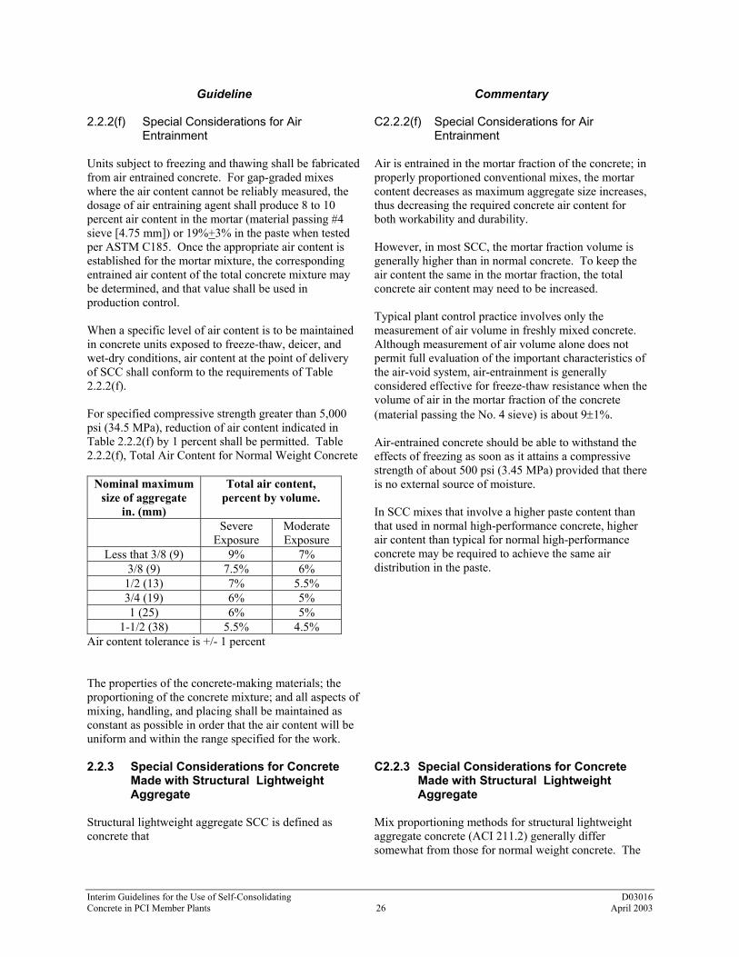
2.2.2(f) Special Considerations for Air Entrainment Units subject to freezing and thawing shall be fabricated from air entrained concrete. For gap-graded mixes where the air content cannot be reliably measured, the dosage of air entraining agent shall produce 8 to 10 percent air content in the mortar (material passing #4 sieve [4.75 mm]) or 19%+3% in the paste when tested per ASTM C185. Once the appropriate air content is established for the mortar mixture, the corresponding entrained air content of the total concrete mixture may be determined, and that value shall be used in production control. When a specific level of air content is to be maintained in concrete units exposed to freeze-thaw, deicer, and wet-dry conditions, air content at the point of delivery of SCC shall conform to the requirements of Table 2.2.2(f). For specified compressive strength greater than 5,000 psi (34.5 MPa), reduction of air content indicated in Table 2.2.2(f) by 1 percent shall be permitted. Table 2.2.2(f), Total Air Content for Normal Weight Concrete
Nominal maximum size of aggregate
in. (mm)
Total air content, percent by volume.
Severe Exposure
Moderate Exposure
Less that 3/8 (9) 9% 7% 3/8 (9) 7.5% 6%
1/2 (13) 7% 5.5% 3/4 (19) 6% 5% 1 (25) 6% 5%
1-1/2 (38) 5.5% 4.5% Air content tolerance is +/- 1 percent The properties of the concrete-making materials; the proportioning of the concrete mixture; and all aspects of mixing, handling, and placing shall be maintained as constant as possible in order that the air content will be uniform and within the range specified for the work.
C2.2.2(f) Special Considerations for Air Entrainment Air is entrained in the mortar fraction of the concrete; in properly proportioned conventional mixes, the mortar content decreases as maximum aggregate size increases, thus decreasing the required concrete air content for both workability and durability. However, in most SCC, the mortar fraction volume is generally higher than in normal concrete. To keep the air content the same in the mortar fraction, the total concrete air content may need to be increased. Typical plant control practice involves only the measurement of air volume in freshly mixed concrete. Although measurement of air volume alone does not permit full evaluation of the important characteristics of the air-void system, air-entrainment is generally considered effective for freeze-thaw resistance when the volume of air in the mortar fraction of the concrete (material passing the No. 4 sieve) is about 9±1%. Air-entrained concrete should be able to withstand the effects of freezing as soon as it attains a compressive strength of about 500 psi (3.45 MPa) provided that there is no external source of moisture. In SCC mixes that involve a higher paste content than that used in normal high-performance concrete, higher air content than typical for normal high-performance concrete may be required to achieve the same air distribution in the paste.
2.2.3 Special Considerations for Concrete Made with Structural Lightweight Aggregate Structural lightweight aggregate SCC is defined as concrete that
C2.2.3 Special Considerations for Concrete Made with Structural Lightweight Aggregate Mix proportioning methods for structural lightweight aggregate concrete (ACI 211.2) generally differ somewhat from those for normal weight concrete. The

Interim Guidelines for the Use of Self-Consolidating D03016 Concrete in PCI Member Plants 27 April 2003
Guideline
Commentary
(a) is made with lightweight aggregates conforming to ASTM C330
(b) has a compressive strength in excess of 2,500 psi
(17.2 MPa) at 28 days of age when tested in accordance with methods stated in ASTM C330
(c) has an air-dry unit weight not exceeding 120 pcf
(1,922 kg/m3) determined in accordance with ASTM C567
Lightweight concrete can also be proportioned with a combination of lightweight aggregate and normal weight aggregate. Lightweight SCC is more easily achieved with lightweight sand than with lightweight coarse aggregates. Special attention is required in the mix design optimization process to keep the lightweight aggregate SCC from segregating. Because there is no standardized method to evaluate the dynamic and static segregation resistance of lightweight aggregate SCC, a careful visual inspection shall be executed in the first production tests, as well as on a regular basis throughout normal production.
principal properties that require modification of proportioning and control procedures are the greater total water absorption and rate of water absorption of lightweight aggregates, plus their low weight. The absorption of water by the aggregate has little effect on compressive strength, provided that enough water is supplied to saturate the aggregate. The moisture content of the aggregate must be known, and adjustments must be made from batch to batch to provide constant water cement ratios and air contents, similar slump flow spreads, and a constant volume of aggregates. In any SCC made with lightweight aggregates, the tendency for the lightweight aggregates to segregate will increase as the size of the lightweight aggregate increases. Should segregation occur, the lightweight aggregates will migrate to the upper portion of the concrete mass. This will lead to varying unit weights across the concrete section and strength heterogeneity in the concrete element.
2.2.3.1 Lightweight Aggregates – Absorption and Moisture Content Lightweight aggregates shall be predampened prior to batching, and the absorbed water shall be accounted for in the mix-proportioning procedure. The supplier of the particular lightweight aggregate should be consulted regarding the necessity for predampening and batching/mixing sequencing requirements. When producing trial batches in the laboratory using the specific gravity method to address lightweight aggregate moisture content, the specific gravity of the lightweight aggregate shall be determined at the moisture content anticipated, prior to use.
C2.2.3.1 Lightweight Aggregates – Absorption and Moisture Content When SCC is made with lightweight aggregates that have a low initial moisture contents (usually less than 8 to 10 percent) and relatively high rates of absorption, it may be desirable to mix the aggregates with one-half or two-thirds of the mixing water for a short period prior to the addition of cement and air-entraining admixture to minimize slump flow spread loss.
2.2.3.2 Lightweight Aggregates – Gradation Differences in the bulk specific gravity of the lightweight aggregate fractions retained on the different sieve sizes shall be taken into account in the mix proportioning for lightweight aggregate SCC.
C2.2.3.2 Lightweight Aggregates – Gradation For normal weight aggregates, the bulk specific gravity of fractions retained on the different sieve sizes are nearly equal. Percentage retained on each sieve size in terms of weight give a true indication of percentages by volume. However, the bulk specific gravity of the various size fractions of lightweight aggregate usually increases as

Interim Guidelines for the Use of Self-Consolidating D03016 Concrete in PCI Member Plants 28 April 2003
Guideline
Commentary
the particle size decreases. This is due to the variation in density that results in some lightweight coarse aggregate particles that may float on water whereas the No. 100 sieve (0.15 mm) material typically has a specific gravity similar to that of normal weight sand. Accordingly, it is the volume occupied, not the weight of the lightweight aggregate material retained on each sieve, that should be used in determining the percentage of voids and paste content. Therefore, lightweight aggregates require a larger percentage of material by weight retained on the finer sieve sizes than do normal weight aggregates to provide an equal aggregate size distribution by volume.
2.2.3.3 Lightweight Aggregates – Air Entrainment The volumetric method of measuring air entrainment, as described in ASTM C173, shall be used to determine air content in lightweight aggregate SCC mixtures.
C2.2.3.3 Lightweight Aggregates – Air Entrainment
2.3 Adjustment of SCC Mixes Laboratory trials should be used to verify properties of the initial mix composition. If necessary, adjustments to the mix composition should be made. Division 3 below outlines the requirements for production qualification of SCC mixes. Additional adjustments should be made as necessary to account for the effects of production mixing, transport, and placement methods.
C2.3 Adjustment of SCC Mixes In the event that satisfactory production performance cannot be obtained with laboratory trial mixes, then consideration should be given to fundamental redesign of the mix. Depending on the apparent problems, the following courses of action may be appropriate. a. The use of additional or different types of filler. b. Modification of the proportions of the sand or the
coarse aggregate. c. The use of a viscosity modifying agent, if not
already included in the mix. d. Adjustment of the dosage of the superplasticizer
(and/or viscosity modifying agent). e. The use of alternative types of superplasticizer
(and/or viscosity modifying agent), which may be more compatible with local materials.
f. Revision of dosage rates of admixtures to modify the water content and hence the water/powder ratio.

Interim Guidelines for the Use of Self-Consolidating D03016 Concrete in PCI Member Plants 29 April 2003
DIVISION 3 GUIDELINES FOR THE PRODUCTION QUALIFICATION OF SELF-CONSOLIDATING CONCRETE 3.1 Introduction From a basic perspective, SCC needs to be both fluid and stable. The required level of fluidity is greatly influenced by the particular application being considered. Therefore, a balanced approach in choosing the correct plastic performance targets for SCC is necessary. It is the task of the producer to select the appropriate test method(s) for qualification of his SCC mixes. The selected test method(s) will depend on the application of the mix and its resulting characteristics. Different qualifications test methods may be appropriate for different mix applications. Figure 3.1 below shows the different variables that affect the required fresh SCC properties. Not only are project and raw material variables considered but also economic variables. As can be seen, an initial perceived value drives the user to trial use of SCC. The challenge is to develop a solution where the realized value of SCC usage is equivalent to the perceived value. This is where the mixture qualification process becomes important. Essentially, the fluidity of SCC is analogous to economic specification of compressive strength; one should design for only that level that is needed for the successful completion of a project.
Figure 3.1 – Variables Involved in Establishing the Required Fresh SCC Properties
Mixture
Element Characteristics
Placement Technique
Raw Material Considerations
Engineering Properties
Fresh SCC Property
Requirements
Are They the Same?
Perceived Value
Actual Value

Interim Guidelines for the Use of Self-Consolidating D03016 Concrete in PCI Member Plants 30 April 2003
There are three levels of tests to consider when using SCC. The first level is that associated with laboratory testing of the mix to determine the initial mix characteristics and confirm the hardened properties of the basic mix design. The second level of testing is the qualification testing necessary to qualify the mix in the production environment. This level includes qualification of the batching process, the mixing process, the transportation and placement process, and finally the finishing and curing process. Finally, the third level of testing is that associated with the quality control of the fresh SCC and the confirmation testing to confirm the hardened properties of the SCC. These levels of testing are schematically shown in Figure 3.1.1 below.
Figure 3.1.1 – Mix Qualification Process Map for SCC
Laboratory Mix Development Laboratory Mix Verification
Production Trials
Production
Production Verification
Quality Control Testing
Acceptance / Rejection
Mix Design-Quality Control Parameters

Interim Guidelines for the Use of Self-Consolidating D03016 Concrete in PCI Member Plants 31 April 2003
Guideline
Commentary
3.1.1 Basic Performance Characteristics of SCC The SCC mix design efforts are geared to producing SCC that fulfills the needs of the projects it will be used on. This section deals with the production qualification efforts necessary to assure that the mix performance confirmed in the laboratory translates appropriately to the production environment.
C3.1.1 Basic Performance Characteristics of SCC
3.2 Concrete Properties and Test Methods
C3.2 Concrete Properties and Test Methods The requirements of the following standards should be met. In instances where minor revisions are required for SCC and they result in deviations from the specifications, these should be discussed with the project engineer of record for disposition.
3.2.1 Hardened Properties/Test Methods to Consider
a. Compressive strength Per ASTM C39, except modify C39 procedures to
delete rodding or vibrating cylinder molds as an element of cylinder manufacture.
b. Flexural strength Per ASTM C293, C78 except modify procedures to
delete rodding or vibrating test specimens as an element of specimen manufacture.
c. Tensile strength Per ASTM C496, except modify procedures to
delete rodding or vibrating test specimens as a element of specimen manufacture.
d. Modulus of elasticity Per ASTM C469.
Some SCC mixes have modulus of elasticity values that are 80 percent of normal high-performance concrete values. In applications where the modulus of elasticity is an important design parameter, this aspect of the SCC mix should be considered in design and confirmed in the production mix.
e. Creep (compressive) creep Per ASTM C469, C801, ACI 209R.
The reported lower modulus of elasticity for some SCC mixes (20 percent reduction reported) suggest the potential for increased creep on elements with high-prestress eccentricities. In applications where the creep characteristics are an important design parameter, this aspect of the SCC mix

Interim Guidelines for the Use of Self-Consolidating D03016 Concrete in PCI Member Plants 32 April 2003
Guideline
Commentary
should be considered in design and confirmed in the production mix.
f. Shrinkage Per ASTM C-157.
SCC mixes must be designed to limit shrinkage. The high powder content of the mixes creates a potential for shrinkage that must be managed. Because of the high powder content, early curing methods must be considered to limit the potential for plastic shrinkage. In applications where the shrinkage characteristics are an important design parameter this aspect of the SCC mix should be considered in design and confirmed in the production mix.
g. Durability
Durability is currently discussed as one of the important advantages of SCC from the point of view that the surface concrete has the potential to be denser and thus less permeable. For durability, critical applications of SCC mixes should be qualified for durability in the same manner as is normal high-performance concrete.
(1) Freeze-thaw resistance Per ASTM C666.
No change from normal high performance concrete in properly designed and implemented SCC mixes. This property can be significantly affected by the stability of the SCC mixture, including the stability of the air voids system.
(2) Chloride permeability Per ASTM C1202.
No change from normal high-performance concrete in properly designed and implemented SCC mixes. This property can be significantly affected by the stability of the SCC mixture, including the stability of the air voids system.
(3) Scaling resistance Per ASTM C-672.
No change from normal high-performance concrete in properly designed and implemented SCC mixes. This property can be significantly affected by the stability of the SCC mixture, including the stability of the air voids system.
(4) Abrasion resistance Per the following ASTM standards: C418 C779 C944 C1138
No change from normal high-performance concrete in properly designed and implemented SCC mixes. This property can be significantly affected by the stability of the SCC mixture, including the stability of the air voids system.
3.2.2 Plastic properties to consider in the production qualification of SCC mixes Self-consolidation in SCC mixtures can be achieved at various fluidity levels (as measured by slump flow). Consolidation is fundamentally controlled by the yield stress of the concrete.
C3.2.2 Plastic properties to consider in the production qualification of SCC mixes Self-consolidation – ACI 309, “The Guide for Consolidation of Concrete” states that consolidation is the process of inducing a closer arrangement of the solid particles in freshly mixed concrete during placement by

Interim Guidelines for the Use of Self-Consolidating D03016 Concrete in PCI Member Plants 33 April 2003
Guideline
Commentary
the reduction of voids.
a. Fluidity – The ability of a concrete mixture to flow. Inherent in this ability is the mixture’s rheological characteristics of yield stress and plastic viscosity.
A balance between the yield stress and plastic viscosity must be reached to achieve self-consolidation and the desired level of placement ease.
b. Yield stress – The internal stress level between elements of the mixture required to initiate flow; below this value no flow will occur.
In SCC, the yield stress value must be low to permit self-consolidation without additionally applied force (i.e., vibration).
c. Plastic viscosity – A material’s internal resistance to flow. Once the yield stress of a mixture is overcome, the plastic viscosity dominates flow.
In practical terms, the plastic viscosity can be seen as “stickiness” or “extra body.” The plastic viscosity of the concrete will affect the ease of placement of a mixture. It will also influence the formed finish.
d. Unconfined fluidity – The mixture's capacity to flow into and completely fill open formwork, characterizes ease of placement (ACI 304).
The unconfined fluidity must be consistent with the overall configuration of the production element for which the SCC is being used.
e. Confined fluidity – The mixture's capacity to flow through tight spaces such as in narrow formwork or through reinforcing steel.
The confined fluidity must be consistent with the level of reinforcement congestion or from geometric complexity that the SCC must flow through in the production element.
f. Ease of placement – Characterizes the amount of labor required to place the concrete during casting operations.
This property is distinct from consolidation as no labor is required for the consolidation of SCC. Depending upon the type of form or element being cast, ease of placement will be controlled by either the mixture’s confined or unconfined fluidity.
g. Stability – Resistance to segregation and/or settlement of aggregates during transport, placement, and subsequent to placement.
SCC must be designed to resist segregation until initial set has occurred.
h. Dynamic stability – That characteristic of a fresh concrete mixture that ensures uniform distribution of all solid particles and air voids as the concrete is being transported and placed.
Dynamic stability provides an indication of passing ability and blocking resistance. It also provides a measure of segregation resistance to prevent segregation resulting from energy inputs during placement and transport (i.e., free fall, etc.). Dynamic stability also provides a measure of resistance to flow separation over distance and around corners in the form.
i. Static stability – That characteristic of a fresh concrete mixture that ensures uniform distribution of all solid particles and air voids once all placement operations are complete and until the onset of setting.
Static stability provides a measure of resistance to the tendency to segregate due to gravity effects. This includes resistance to the tendency to settle, air migration within the mix, and bleeding.
j. Filling capacity – A combination of fluidity and stability (passing ability) characteristics. It is the ability of the concrete to completely fill intricate formwork or formwork containing obstacles, such as reinforcement.

Interim Guidelines for the Use of Self-Consolidating D03016 Concrete in PCI Member Plants 34 April 2003
Guideline
Commentary
3.2.3 Test methods to evaluate the plastic properties of SCC for production qualification Table 3.2.3 lists the test available to evaluate the plastic properties of SCC. Table 3.2.4 lists additional special purpose tests that may be of value in particular circumstances.
C3.2.3 Test methods to evaluate the plastic properties of SCC for production qualification See Appendix 1 for discussion of SCC tests.
Table 3.2.3 – SCC Plastic Properties Test Methods
Test Method Measured Stability Characteristic
*L-Box Passing ability/blocking resistance
**U-Box Passing ability/blocking resistance
*J-Ring Passing ability/blocking resistance
*Slump Flow, T-50, and Visual Stability Index (VSI) Flow separation resistance, stability/settlement resistance, air migration, relative viscosity
Inverted Slump Flow, and Visual Stability Index (VSI) Flow separation resistance, stability/settlement resistance, air migration, relative viscosity
Table 3.2.4 – SCC Tests for Special Situations
Test Method Measured Stability Characteristic
Screen Stability Test Static segregation/settlement resistance
Bleeding Test (French) Dynamic segregation resistance
Bleeding Test (ASTM C 232) Propensity to bleeding
*V-Funnel Passing ability/blocking resistance, viscosity
*Orimet with J-Ring Dynamic segregation resistance, passing ability/blocking resistance
*also measures fluidity **also measures self-consolidation
a. Slump flow – This test is performed by using the standard Abrams cone. But instead of measuring the slump, the diameter of the concrete paddy formed upon lifting of the slump cone is measured and recorded. There are no restrictions for the concrete to flow through (see Appendix 1).
This method helps to quantify the ease of placement level provided by the concrete. Measuring the time for the spread to reach a diameter of 50 cm (19.68 inches) (T-50) provides an indication of the relative viscosity of the mixture. Note: in North America, the T-20 time is frequently used. This is the time for the spread to reach a diameter of 20 inches. A combination of the slump flow and T-50 time can provide a clear indication of relative SCC viscosity.
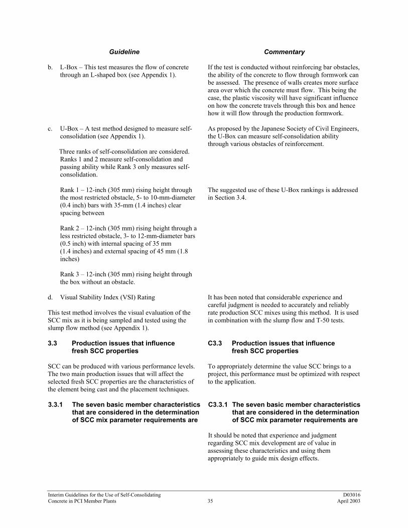
Interim Guidelines for the Use of Self-Consolidating D03016 Concrete in PCI Member Plants 35 April 2003
Guideline
Commentary
b. L-Box – This test measures the flow of concrete through an L-shaped box (see Appendix 1).
If the test is conducted without reinforcing bar obstacles, the ability of the concrete to flow through formwork can be assessed. The presence of walls creates more surface area over which the concrete must flow. This being the case, the plastic viscosity will have significant influence on how the concrete travels through this box and hence how it will flow through the production formwork.
c. U-Box – A test method designed to measure self-consolidation (see Appendix 1).
Three ranks of self-consolidation are considered.
Ranks 1 and 2 measure self-consolidation and passing ability while Rank 3 only measures self-consolidation.
As proposed by the Japanese Society of Civil Engineers, the U-Box can measure self-consolidation ability through various obstacles of reinforcement.
Rank 1 – 12-inch (305 mm) rising height through the most restricted obstacle, 5- to 10-mm-diameter (0.4 inch) bars with 35-mm (1.4 inches) clear spacing between
The suggested use of these U-Box rankings is addressed in Section 3.4.
Rank 2 – 12-inch (305 mm) rising height through a less restricted obstacle, 3- to 12-mm-diameter bars (0.5 inch) with internal spacing of 35 mm (1.4 inches) and external spacing of 45 mm (1.8 inches)
Rank 3 – 12-inch (305 mm) rising height through the box without an obstacle.
d. Visual Stability Index (VSI) Rating This test method involves the visual evaluation of the SCC mix as it is being sampled and tested using the slump flow method (see Appendix 1).
It has been noted that considerable experience and careful judgment is needed to accurately and reliably rate production SCC mixes using this method. It is used in combination with the slump flow and T-50 tests.
3.3 Production issues that influence fresh SCC properties SCC can be produced with various performance levels. The two main production issues that will affect the selected fresh SCC properties are the characteristics of the element being cast and the placement techniques.
C3.3 Production issues that influence fresh SCC properties To appropriately determine the value SCC brings to a project, this performance must be optimized with respect to the application.
3.3.1 The seven basic member characteristics that are considered in the determination of SCC mix parameter requirements are
C3.3.1 The seven basic member characteristics that are considered in the determination of SCC mix parameter requirements are
It should be noted that experience and judgment regarding SCC mix development are of value in assessing these characteristics and using them appropriately to guide mix design effects.

Interim Guidelines for the Use of Self-Consolidating D03016 Concrete in PCI Member Plants 36 April 2003
Guideline
Commentary
(a) Member Characteristic 1 - Reinforcement Level This relates to the minimum clear spacing between elements of reinforcement, as well as between the reinforcement and the form walls. The more congested the element is, the higher the potential for aggregate bridging and blocking, which leads to separation of the mixture constituents.
C(a) Member Characteristic 1 - Reinforcement Level The Japanese Society of Civil Engineers bases their ranking of the required properties for SCC mixtures on the reinforcement level in the element. Pass or fail is determined through the U-Box test with the appropriate obstacle included in the U Box apparatus. The reinforcement level will help determine the required level of dynamic stability and fluidity. A high level of reinforcement will require a higher level of fluidity (as measured by slump flow) and adequate passing ability.
(b) Member Characteristic 2 - Element Shape Intricacy This rates the element shape with regard to the difficulty a mixture will have in filling a form without leaving significant voids or honeycombs internally and on the formed surface.
C(b) Member Characteristic 2 - Element Shape Intricacy For example, with SCC, it is easier to produce a round column with few surface voids than it is to produce a square column with few voids. This difference is due to the fact that the round column does not have edges or corners that affect concrete flow as they do in a square column. The evaluation of element intricacy will help determine the required fluidity level of the mixture. More intricate shapes will require higher fluidity levels.
(c) Member Characteristic 3 - Element Depth This refers to the depth to which the plastic concrete will be placed and the resulting head height of the plastic concrete.
C(c) Member Characteristic 3 - Element Depth A 10-m (33 feet) column has greater segregation potential than a 100-mm (4 inches) slab, simply due to the cumulative effect as a result of depth. The element depth will help determine the required level of dynamic and static stability. The depth will also affect the fluidity level required due to head pressure.
(d) Member Characteristic 4 - Importance of the Surface Finish This rates the necessity of having a premium quality surface finish that will be dictated by the characteristics of the concrete mixture itself.
C(d) Member Characteristic 4 - Importance of the Surface Finish For example, the finish for a residential slab, although affected by mixture properties, is mainly determined by the finishing technique. This is in contrast to an architectural panel or column where the surface in question is formed and mainly controlled by the flow properties of the SCC. Improved surface appearance is generally obtained with higher levels of fluidity with controlled viscosity.
(e) Member Characteristic 5 - Element Length This is a rating of the average distance that the concrete must flow from the discharge point to completely fill the form.
C(e) Member Characteristic 5 - Element Length Element length considerations help determine the required SCC fluidity level and dynamic stability.

Interim Guidelines for the Use of Self-Consolidating D03016 Concrete in PCI Member Plants 37 April 2003
Guideline
Commentary
(f) Member Characteristic 6 - Coarse Aggregate Content When producing an exposed aggregate finish, high volumes of coarse aggregate may be required to achieve the desired visual effect. This characteristic was created to cover this application.
C(f) Member Characteristic 6 - Coarse Aggregate Content Coarse aggregate content is one of the main issues controlling passing ability; this must be taken into consideration when proportioning the SCC mixture. The type of coarse aggregate (crushed or round) and aspect ratio of the coarse aggregate particles are also a mix design consideration.
(g) Member Characteristic 7 - Wall Thickness The spacing between walls in the formwork will affect the ability of the SCC mixture to fill the element form. It will also affect the ability of entrapped voids to escape without leaving any surface defects.
C(g) Member Characteristic 7 - Wall Thickness Thin walls usually require a higher fluidity level.
3.3.2 Placement Techniques Placement technique can have a significant impact on the flowing characteristics of the SCC.
C3.3.2 Placement Techniques Historically, the energy delivered by the placement technique has not been considered as an important variable in precast/prestressed concrete production. One can compare placement techniques based on the rate at which the concrete is discharged, the total volume of concrete being discharged, and whether or not the placement process is continuous or discontinuous. The higher the relative energy delivered, the lower the fluidity level required for the SCC to flow the same distance. In addition, situations where higher energy is delivered through placement technique may require increased awareness regarding stability.
Table 3.3.2 – Relative Energy Delivered by Different Placement Techniques Placement Technique
Discharge Rate
Discharge Type
Single Discharge Volume
Relative Energy Delivered
Truck Discharge High Continuous High High Pumping Medium/High Continuous Medium High/Medium
Crane and Bucket High Discontinuous Low Medium Auger
(Tuckerbuilt) Discharge
Low/Medium Continuous Medium Low/Medium
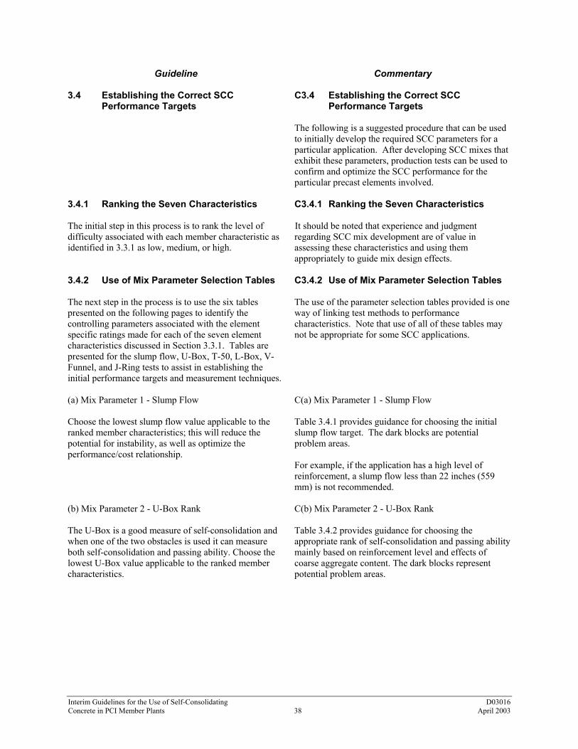
Interim Guidelines for the Use of Self-Consolidating D03016 Concrete in PCI Member Plants 38 April 2003
Guideline
Commentary
3.4 Establishing the Correct SCC Performance Targets
C3.4 Establishing the Correct SCC Performance Targets The following is a suggested procedure that can be used to initially develop the required SCC parameters for a particular application. After developing SCC mixes that exhibit these parameters, production tests can be used to confirm and optimize the SCC performance for the particular precast elements involved.
3.4.1 Ranking the Seven Characteristics The initial step in this process is to rank the level of difficulty associated with each member characteristic as identified in 3.3.1 as low, medium, or high.
C3.4.1 Ranking the Seven Characteristics It should be noted that experience and judgment regarding SCC mix development are of value in assessing these characteristics and using them appropriately to guide mix design effects.
3.4.2 Use of Mix Parameter Selection Tables The next step in the process is to use the six tables presented on the following pages to identify the controlling parameters associated with the element specific ratings made for each of the seven element characteristics discussed in Section 3.3.1. Tables are presented for the slump flow, U-Box, T-50, L-Box, V-Funnel, and J-Ring tests to assist in establishing the initial performance targets and measurement techniques.
C3.4.2 Use of Mix Parameter Selection Tables The use of the parameter selection tables provided is one way of linking test methods to performance characteristics. Note that use of all of these tables may not be appropriate for some SCC applications.
(a) Mix Parameter 1 - Slump Flow Choose the lowest slump flow value applicable to the ranked member characteristics; this will reduce the potential for instability, as well as optimize the performance/cost relationship.
C(a) Mix Parameter 1 - Slump Flow Table 3.4.1 provides guidance for choosing the initial slump flow target. The dark blocks are potential problem areas. For example, if the application has a high level of reinforcement, a slump flow less than 22 inches (559 mm) is not recommended.
(b) Mix Parameter 2 - U-Box Rank The U-Box is a good measure of self-consolidation and when one of the two obstacles is used it can measure both self-consolidation and passing ability. Choose the lowest U-Box value applicable to the ranked member characteristics.
C(b) Mix Parameter 2 - U-Box Rank Table 3.4.2 provides guidance for choosing the appropriate rank of self-consolidation and passing ability mainly based on reinforcement level and effects of coarse aggregate content. The dark blocks represent potential problem areas.

Interim Guidelines for the Use of Self-Consolidating D03016 Concrete in PCI Member Plants 39 April 2003
Table 3.4.1 Slump Flow Parameter Determination
Dark blocks represent potential problem areas.
Tables 3.4.1 through 3.4.5 from Daczko, J.A., Constantiner, D., "Rheodynamic Concrete"TM Proceedings of the 43rd Congresso Brasileiro do Concreto, 2001.
Slump flow
<22"
22-26"
>26"
LowMediumReinforcement
LevelHighLow
MediumElement ShapeIntricacy
HighLow
MediumElement DepthHighLow
MediumSurface FinishImportance
HighLow
MediumElement LengthHighLow
MediumWall ThicknessHighLow
Medium
Mem
ber C
hara
cter
istic
s
Coarse AggregateContent
HighLow
MediumPlacementEnergy
High

Interim Guidelines for the Use of Self-Consolidating D03016 Concrete in PCI Member Plants 40 April 2003
Table 3.4.2 U-Box Ranking Parameter Determination
(Refer to 3.2.3C for definition of U-Box ranks.)
Dark blocks represent potential problem areas.
U-Box R
ank 3
Rank 2
Rank 1
Low Medium Reinforcement
Level High Low
Medium Element Shape Intricacy
High Low
Medium Element Depth High Low
Medium Surface Finish Importance
High Low
Medium Element Length High Low
Medium Wall Thickness High Low
Medium
Mem
ber C
hara
cter
istic
s
Coarse Aggregate Content
High Low
Medium
Placement Energy
High

Interim Guidelines for the Use of Self-Consolidating D03016 Concrete in PCI Member Plants 41 April 2003
Table 3.4.3 T-50 Time Parameter Determination
(The values for T-50 time are in seconds.)
Dark blocks represent potential problem areas.
T 50 time
<3 sec
3-5 sec
>5 secLow
MediumReinforcementLevel
HighLow
MediumElement ShapeIntricacy
HighLow
MediumElement DepthHighLow
MediumSurface FinishImportance
HighLow
MediumElement LengthHighLow
MediumWall ThicknessHighLow
Medium
Mem
ber C
hara
cter
istic
s
Coarse AggregateContent
HighLow
MediumPlacementEnergy
High

Interim Guidelines for the Use of Self-Consolidating D03016 Concrete in PCI Member Plants 42 April 2003
Table 3.4.4 L-Box Ratio Parameter Determination
(The values stated for the L-Box are the ratio of h2/h1.)
Dark blocks represent potential problem areas.
L-Box
<75
75-90
>90
LowMediumReinforcement
LevelHighLow
MediumElement ShapeIntricacy
HighLow
MediumElement DepthHighLow
MediumSurface FinishImportance
HighLow
MediumElement LengthHighLow
MediumWall ThicknessHighLow
Medium
Mem
ber C
hara
cter
istic
s
Coarse AggregateContent
HighLow
MediumPlacementEnergy
High

Interim Guidelines for the Use of Self-Consolidating D03016 Concrete in PCI Member Plants 43 April 2003
Table 3.4.5 V-Funnel Time Parameter Determination
(The values for the V-Funnel are in seconds.)
Dark blocks represent potential problem areas.
V-Funnel
<6 sec
6-10
>10
LowMediumReinforcement
LevelHighLow
MediumElement ShapeIntricacy
HighLow
MediumElement DepthHighLow
MediumSurface FinishImportance
HighLow
MediumElement LengthHighLow
MediumWall ThicknessHighLow
Medium
Mem
ber C
hara
cter
istic
s
Coarse AggregateContent
HighLow
MediumPlacementEnergy
High
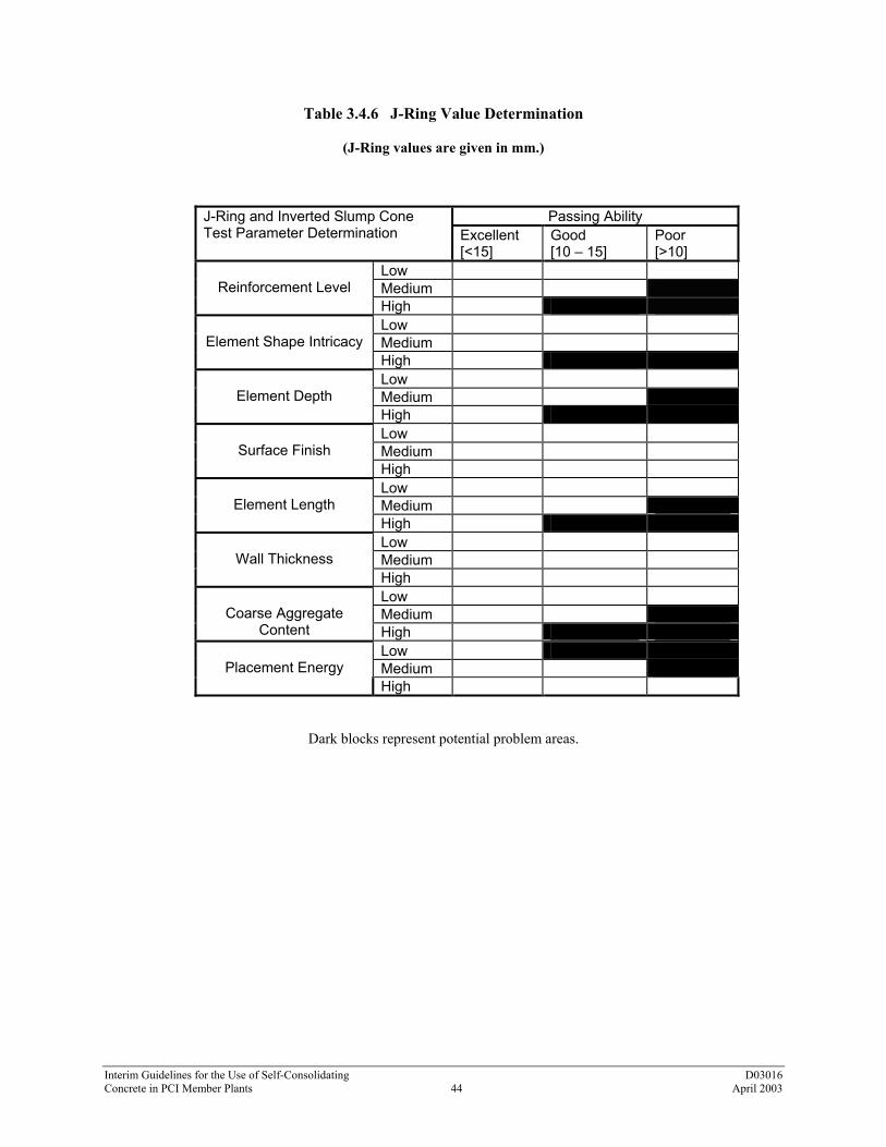
Interim Guidelines for the Use of Self-Consolidating D03016 Concrete in PCI Member Plants 44 April 2003
Table 3.4.6 J-Ring Value Determination
(J-Ring values are given in mm.)
Passing Ability J-Ring and Inverted Slump Cone
Test Parameter Determination Excellent [<15]
Good [10 – 15]
Poor [>10]
Low Medium
Reinforcement Level
High Low Medium
Element Shape Intricacy
High Low Medium
Element Depth
High Low Medium
Surface Finish
High Low Medium
Element Length
High Low Medium
Wall Thickness
High Low Medium
Coarse Aggregate
Content High Low Medium
Placement Energy
High
Dark blocks represent potential problem areas.

Interim Guidelines for the Use of Self-Consolidating D03016 Concrete in PCI Member Plants 45 April 2003
Guideline
Commentary
(c) Mix Parameter 3 - T-50 Time The T-50 time will be affected by both the final fluidity level, as well as the plastic viscosity. For a given slump flow range, this test is a good measure of a mixtures plastic viscosity. Choose the lowest T-50 time applicable to the ranked member characteristics.
C(c) Mix Parameter 3 – T-50 Time Table 3.4.3 provides guidance for establishing T-50 times based on application requirements. The dark blocks represent potential problem areas.
(d) Mix Parameter 4 – L-Box Ratio Choose the lowest L-Box ratio applicable to the ranked member characteristics.
C(d) Mix Parameter 4 – L-Box Ratio Table 3.4.4 provides guidance for establishing L-Box ratios based on application requirements. The dark blocks represent potential problem areas.
(e) Mix Parameter 5 – V-Funnel Time Choose the highest V-Funnel time applicable to the ranked member characteristics.
C(e) Mix Parameter 5 – V-Funnel Time Table 3.4.5 provides guidance for establishing V-Funnel times based on application requirements. The dark blocks represent potential problem areas.
(f) Mix Parameter 6 – J-Ring Value Choose lowest J-Ring value applicable to the ranked member characteristics.
C(f) Mix Parameter 6 – J-Ring Value Table 3.4.6 provides guidance for establishing J-Ring values based on application requirements. The dark blocks represent potential problem areas.
3.5 Refinement of Targets Once an SCC mix with the required plastic properties has been developed the next step is to refine both the mix and production processes associated with its use to provide an optimum production mix that meets all of the following additional requirements.
C3.5 Refinement of Targets
3.5.1 Required Hardened Properties The SCC shall meet or exceed project specifications and the requirements of the following standards. ACI 211 – Standard Practice for Selecting Proportions for Concrete ACI 214 – Recommended Practice for Evaluation of Strength Test Results of Concrete ACI 301 – Specifications for Structural Concrete for Buildings ACI 318 – Building Code Requirements for Structural Concrete
C3.5.1 Required Hardened Properties In instances where minor revisions are required for SCC and they result in deviations from the specifications, these should be discussed with the project engineer of record for disposition.

Interim Guidelines for the Use of Self-Consolidating D03016 Concrete in PCI Member Plants 46 April 2003
Guideline
Commentary
3.5.2 Required Fresh Properties The fresh SCC properties developed as a result of the use of the tables presented in Section 3.4 should be confirmed in actual production conditions to be optimal or the mix design shall be adjusted as required. The requirements of the following standards should be met. ACI 211– Standard Practice for Selecting Proportions for Concrete ACI 309R – Guidelines for Consolidation of Concrete ACI 304R – Guidelines for Measuring, Mixing, Transporting, and Placing Concrete
C3.5.2 Required Fresh Properties Varying field conditions may require mix adjustments to ensure project concrete specifications are met; consider ambient environmental conditions, formwork geometries, placement methods, placement intervals, reinforcements, etc. In instances where minor revisions are required for SCC and they result in deviations from the specifications, these should be discussed with the project engineer of record for disposition.
3.5.3 Tolerances on Hardened and Plastic Parameters The achievement of the minimum and maximum hardened and plastic concrete tolerances should be substantiated through mix design qualification in the context of project specifications. The requirements of the following standards should be met. ACI 211 – Standard Practice for Selecting Proportions for Concrete ACI 214 – Recommended Practices for Evaluation of Strength Tests of Concrete ACI 301 – Specifications for Structural Concrete for Buildings ACI 318 – Building Code Requirements for Structural Concrete
C3.5.3 Tolerances on Hardened and Plastic Parameters In instances where minor revisions are required for SCC and they result in deviations from the specifications, these should be discussed with the project engineer of record for disposition.
3.5.4 Mixture Robustness SCC mixtures are high-performance concrete mixtures; therefore, they are more sensitive to constituent material consistency and quantity fluctuations during production. Fluctuations in raw materials, such as gradations and moisture contents, can have dramatic influence on the stability of the SCC mixtures. Batching fluctuations can also significantly affect both stability and fluidity.
C3.5.4 Mixture Robustness During the mixture qualification process, it is recommended that some time be taken to investigate the sensitivity of the particular design and raw materials in use to fluctuations in fluidity level due to variations in moisture content (extra water). In addition, it is recommended to investigate the affect of slump flow variation on stability for a particular mix design and set of materials.
(a) Robustness Parameter 1 - Fluidity Forgiveness Because the level of fluidity has a direct impact on the stability of an SCC mixture, once a suitable mixture has been developed, determine the level of fluidity (slump flow) at which the mixture becomes unstable.
C(a) Robustness Parameter 1 – Fluidity Forgiveness This should be done initially by varying the quantity of high-range water reducer. When examining this characteristic, take into consideration the fact that some HRWRs will lose slump flow more rapidly than others. Batch a mixture and measure slump flow and determine the Visual Stability Index (VSI) rating, add successive amounts of HRWR measuring slump flow, and VSI at each addition. Record at what level of slump flow the

Interim Guidelines for the Use of Self-Consolidating D03016 Concrete in PCI Member Plants 47 April 2003
Guideline
Commentary mixture becomes unstable. Use this information to aid in controlling stability during daily production.
(a) Robustness Parameter 1 - Fluidity Forgiveness Because the level of fluidity has a direct impact on the stability of an SCC mixture, once a suitable mixture has been developed, determine the level of fluidity (slump flow) at which the mixture becomes unstable.
C(a) Robustness Parameter 1 – Fluidity Forgiveness This should be done initially by varying the quantity of high-range water reducer. When examining this characteristic, take into consideration the fact that some HRWRs will lose slump flow more rapidly than others. Batch a mixture and measure slump flow and determine the Visual Stability Index (VSI) rating, add successive amounts of HRWR measuring slump flow, and VSI at each addition. Record at what level of slump flow the mixture becomes unstable. Use this information to aid in controlling stability during daily production.
(b) Robustness Parameter 2 - Water Sensitivity Fluctuations in raw material moisture contents and thus total mix water content will have a direct impact on both the fluidity level and the stability of the SCC mix. Thus, the water sensitivity of the production SCC mix should be determined.
C(b) Robustness Parameter 2 – Water Sensitivity Once a mixture has been developed, determine the sensitivity to water fluctuations by batching a mixture and adding successive amounts of water to the batch. At each of these additions, measure the slump flow and VSI. Determine the point at which the mixture becomes unstable. Use this information to aid in controlling stability during daily production.
3.6 Use of Mock-Ups in Production Qualification of Mixes It is recommended that as part of mix design qualification/development each SCC mix be subject to actual production-based confirmation.
C3.6 Use of Mock-ups in Production Qualification of Mixes This confirmation should address both plastic and hardened states, for actual correlation to project product suitability. The following are suggested areas for consideration.
3.6.1 Test Pieces The actual performance of an SCC mix in a test piece can be used to confirm production methods and assure that the SCC mix results in a homogeneous element without segregation.
C3.6.1 Test Pieces
Modeling/simulation – test pours of complex portions of precast elements can be used to optimize placement techniques and details of the element itself to assure successful use of SCC on the full-scale production unit.
3.6.2 Production Mixing Qualification for SCC An important qualification procedure for SCC mixes is to run trial batches from production mixers and adjust the mix as necessary to attain desired properties.
C3.6.2 Production Mixing Qualification for SCC There may be significant differences in the fresh performance of SCC mixed in small lab mixers as part of the mix design process and the same mix produced in a production mixer in the precast plant.

Interim Guidelines for the Use of Self-Consolidating D03016 Concrete in PCI Member Plants 48 April 2003
Guideline
Commentary
(a) Qualifying mixing equipment capability. Rated mixing times for normal concrete may vary with SCC mixes and thus should be confirmed with actual trial mixes in the production mixers that will be used in the plant.
C(a) Qualifying mixing equipment capability. While most mixers in use in production can successfully mix SCC, some mixer types handle SCC more efficiently than others.
(b) Qualifying material charging sequence. For each SCC mix, a charging sequence that produces SCC of the desired fresh properties shall be developed. Once established, this charging sequence shall be employed for all SCC batches.
C(b) Qualifying material charging sequence. Charging sequence may be more important than for non-SCC mixes. This is especially true of the charging sequence of admixtures, powders, and water.
(c) Qualifying mix cycle time. For each SCC mix, a mixing time sequence and duration that produces SCC of the desired fresh properties shall be developed. Once established, this mixing cycle time shall be employed for all SCC batches.
C(c) Qualifying mix cycle time. Elements of the cycle time (time mixed for different elements of the charging cycle) may have a significant effect on SCC properties.
3.6.3 Qualifying Mix Adjustments Required for Field Applications/Mix Tolerances It is important to pay special attention to mix performance parameters when changes in field conditions develop. These may require a revision to the mix design for acceptable SCC performance.
C3.6.3 Qualifying Mix Adjustments Required for Field Applications/Mix Tolerances Field conditions (temperature and humidity variations, moisture variations in aggregates as result of weather, etc) may have a significant effect on SCC mixes that requires adjustment to the mix. Because mix adjustments to SCC mixes may be more complex than similar adjustments to normal high-performance concrete, typical field adjustments should be qualified in advance.
3.6.4 Qualification of Placement Methods More efficient placement is one of the important advantages of SCC. However, as with normal concrete, there are methods of placement that are more successful than others.
C3.6.4 Qualification of Placement Methods Different types of precast elements may require differing approaches to placement.
(a) Transportation/handling techniques. Some SCC has a thixotropic nature. This tendency to jell when the material has been at rest for a short period must be considered in the transportation and handling techniques used for the material.
(b) Placement methods/conditions. SCC placement methods for substantially different elements shall be qualified as producing acceptable elements.
C(b) Placement methods/conditions. Placement of SCC, while requiring less on-the-form manpower, may require advance planning to assure acceptable finishes without seam lines or visible flow lines on the surface of the element.

Interim Guidelines for the Use of Self-Consolidating D03016 Concrete in PCI Member Plants 49 April 2003
Guideline
Commentary
(c) Placement distance. SCC placement methods shall be qualified at the placement distance representative of the production placement situation.
C(c) Placement distance. Selecting deposition locations and determining the optimal length of flow is one of the parameters to be determined from test placements. If pumped, the length of the pumping line is a variable that could affect the flow characteristics of the material.
(d) Free-fall distance. Determination of maximum free-falling distances through reinforcing shall be qualified through the use of production mock-ups or by other means to assure acceptable uniformity in the production element.
C(d) Free-fall distance. SCC can be allowed to free fall a greater distance than normal concrete. Free falling through reinforcing in a form, however, is a very severe test that may tend to cause segregation. Properly designed and qualified SCC mixes can, in some instances, free fall heights in excess of 10 feet (3 m) without segregation.
(e) Lateral flow distance from charging point. The detailed nature of the element being produced will determine the acceptable lateral flow distance from the charging point. Thus, this is something that should be investigated through the use of production mock-ups or by other means to assure acceptable uniformity in the production element.
C(e) Lateral flow distance from charging point. In some instances, precast elements of significant size and length can be placed from one concrete deposition point with SCC.
(f) Lift height/head pressures. The consequences of high head heights on the performance of SCC in a particular element configuration is something that should be investigated through the use of production mock-ups or other means to assure acceptable uniformity in the production element.
C(f) Lift height/head pressures. The head pressures associated with increasing lift heights may have an affect on the stability of the SCC mix.
3.6.5 Curing Mixes may require adjustment if set times prove to be longer than normal and, thus, require a delay in the start of temperature increases associated with accelerated curing operations.
C3.6.5 Curing Reduction in placement time may provide additional time for curing within the daily production cycle. At the same time, initial set times for SCC should be confirmed as they have the potential for being different from normal concrete.
3.6.6 Selection/Development of Diagnostic Testing Procedures and Tolerances As discussed above, new measures are needed to assess fresh concrete and also to confirm the performance in production elements.
C3.6.6 Selection/Development of Diagnostic Testing Procedures and Tolerances Slump as the historic measure of acceptance for a concrete mix has no value in the quality control of SCC batches. Thus, new measures and a new awareness among production and quality assurance staff must be developed as basis for acceptance/rejection in terms of project – product design requirements.

Interim Guidelines for the Use of Self-Consolidating D03016 Concrete in PCI Member Plants 50 April 2003
Guideline
Commentary
(a) Measures to confirm plastic performance. The tests listed in Tables 3.2.3 and 3.2.4 (described in Appendix 1) are available to assist in the testing to assure acceptability of SCC. The requirements to confirm both stability and other plastic properties suggests that additional measures over and above those required for normal concrete are appropriate.
C(a) Measures to confirm plastic performance. The optimum combination of theses test methods has yet to be defined. At the least, it should be stated that production quality testing should not be less for SCC than that required for normal concrete.
(b) Translation of plastic metrics to hardened performance. Table 3.6.6 lists conventional concrete tests as described in industry standards that can be used to confirm the hardened performance of SCC.
C(b) Translation of plastic metrics to hardened performance. Because of the potential variation in stability and the resulting potential for segregation, additional consideration should be given to methods to confirm uniformity (distribution of coarse aggregate and entrained air).
Table 3.6.6 – Conventional Concrete Tests Compressive strength
Uniformity Form finishes Tensile strength
Unit weight Air content Modulus of Elasticity
Bond
Flexural strength Deformation 3.6.7 Define Specific QC Parameters to Be Controlled and Monitored Identify parameters based on sufficient existing mix design history/performance and/or from production trials and finished product performance to ensure production regularity and to satisfy job requirements.
C3.6.7 Define Specific QC Parameters to Be Controlled and Monitored PCI producers often rely on a long and successful history of concrete mix design and constituent material performance in planning their quality assurance programs. It is important to recognize that initially this historical background is not available with SCC to guide the development of effective and economical quality assurance approaches. Thus until this background has been developed by the industry and within individual producer plants increased attention to the items discussed above is warranted. As with the introduction of any new material or procedure, the proper new methods must first displace the old methods and perceptions. Concrete technology is the fundamental technology around which precast production is based. Technology and experience relative to normal concrete is deeply ingrained into all levels of the precast operation. Thus, changing the old methods and procedures to correctly and efficiently adapt to the new requirements of SCC in ways that also capture the benefits of the material should not be underestimated.

Interim Guidelines for the Use of Self-Consolidating D03016 Concrete in PCI Member Plants 51 April 2003
Guideline
Commentary
3.7 Employee Training
C3.7 Employee Training
3.7.1 Quality Control Department Training The day-to-day production of quality SCC requires that all inspection personnel be properly trained.
C3.7.1 Quality Control Department Training The objectives, methods, uniformity of practice, inspection, and record keeping required in the production of SCC are no less important than any other facet of the quality control program.
(a) Quantitative and qualitative analyses. Every quality control inspector involved in the production and testing of SCC must be trained in the proper testing procedures for the various test methods. In addition to understanding how to properly conduct the tests, the quality control personnel must also be able to evaluate the results of those tests.
C(a) Quantitative and qualitative analyses. If the desired quality and value of an SCC mixture is to be realized, the quality control personnel must understand the engineering properties, placement techniques, element characteristics, and raw materials considerations that are used to determine mixture proportions and fresh concrete properties.
3.7.2 Production Personnel Training In order to produce SCC that achieves the desired quality and produces the desired value, it is imperative that production personnel receive training in the effects that production methods can have on these properties.
C3.7.2 Production Personnel Training Production personnel need to understand that each SCC mixture has been carefully designed to take into account all aspects of material selection, form condition, placement methods, and engineering properties. When expected quality or value is not being achieved, the contribution of knowledgeable production personnel is vital to taking proper corrective action.

Interim Guidelines for the Use of Self-Consolidating D03016 Concrete in PCI Member Plants 52 April 2003
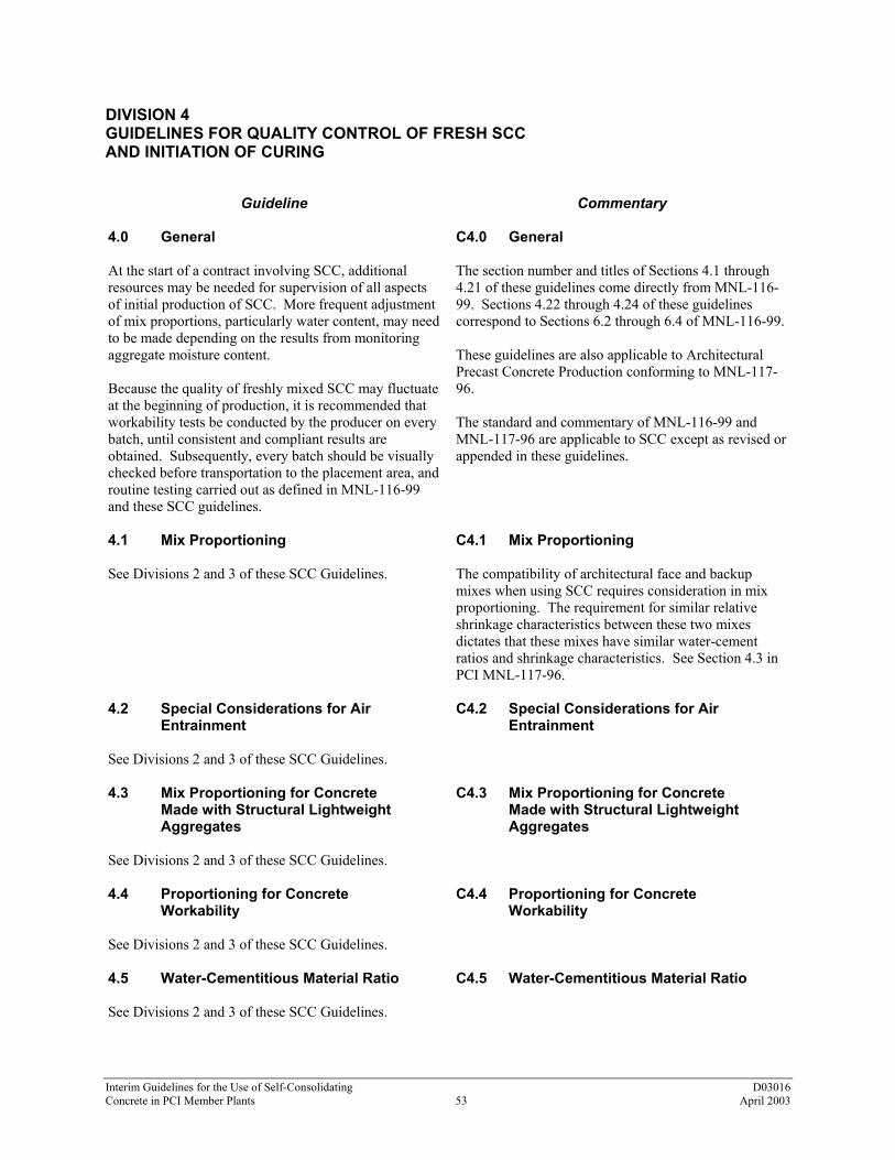
Interim Guidelines for the Use of Self-Consolidating D03016 Concrete in PCI Member Plants 53 April 2003
DIVISION 4 GUIDELINES FOR QUALITY CONTROL OF FRESH SCC AND INITIATION OF CURING
Guideline
Commentary
4.0 General At the start of a contract involving SCC, additional resources may be needed for supervision of all aspects of initial production of SCC. More frequent adjustment of mix proportions, particularly water content, may need to be made depending on the results from monitoring aggregate moisture content. Because the quality of freshly mixed SCC may fluctuate at the beginning of production, it is recommended that workability tests be conducted by the producer on every batch, until consistent and compliant results are obtained. Subsequently, every batch should be visually checked before transportation to the placement area, and routine testing carried out as defined in MNL-116-99 and these SCC guidelines.
C4.0 General The section number and titles of Sections 4.1 through 4.21 of these guidelines come directly from MNL-116-99. Sections 4.22 through 4.24 of these guidelines correspond to Sections 6.2 through 6.4 of MNL-116-99. These guidelines are also applicable to Architectural Precast Concrete Production conforming to MNL-117-96. The standard and commentary of MNL-116-99 and MNL-117-96 are applicable to SCC except as revised or appended in these guidelines.
4.1 Mix Proportioning See Divisions 2 and 3 of these SCC Guidelines.
C4.1 Mix Proportioning The compatibility of architectural face and backup mixes when using SCC requires consideration in mix proportioning. The requirement for similar relative shrinkage characteristics between these two mixes dictates that these mixes have similar water-cement ratios and shrinkage characteristics. See Section 4.3 in PCI MNL-117-96.
4.2 Special Considerations for Air Entrainment See Divisions 2 and 3 of these SCC Guidelines.
C4.2 Special Considerations for Air Entrainment
4.3 Mix Proportioning for Concrete Made with Structural Lightweight Aggregates See Divisions 2 and 3 of these SCC Guidelines.
C4.3 Mix Proportioning for Concrete Made with Structural Lightweight Aggregates
4.4 Proportioning for Concrete Workability See Divisions 2 and 3 of these SCC Guidelines.
C4.4 Proportioning for Concrete Workability
4.5 Water-Cementitious Material Ratio See Divisions 2 and 3 of these SCC Guidelines.
C4.5 Water-Cementitious Material Ratio

Interim Guidelines for the Use of Self-Consolidating D03016 Concrete in PCI Member Plants 54 April 2003
Guideline
Commentary
4.6 Effects of Admixtures See Divisions 2 and 3 of these SCC Guidelines.
C4.6 Effects of Admixtures
4.7 Storage and Handling of Concrete Materials Section 4.7 of MNL-116-99 is applicable to SCC without revision
C4.7 Storage and Handling of Concrete Materials
4.8 Batching Equipment Tolerances Section 4.8 of MNL-116-99 is applicable to SCC without revision
C4.8 Batching Equipment Tolerances
4.9 Scale Requirements Section 4.9 of MNL-116-99 is applicable to SCC without revision.
C4.9 Scale Requirements
4.10 Requirements for Water Measuring Equipment Section 4.10 of MNL-116-99 is applicable to SCC without revision. However, note water control requirements as outlined in Section 2.2.2.
C4.10 Requirements for Water Measuring Equipment The water sensitivity of each SCC mix is to be determined as part of the production qualification process. This effort will define the tolerances to which total mix water must be controlled.
4.11 Requirements for Batchers and Mixing Plants Section 4.11 of MNL-116-99 is applicable to SCC except as noted in 4.11.2.
C4.11 Requirements for Batchers and Mixing Plants
4.11.2 Requirements for Concrete Mixers Section 4.11.2 of MNL-116-99 is applicable to SCC with the following revision. The consistency meter must be recalibrated for each SCC mix design so as to determine as precisely as possible the mixing duration necessary to obtain a homogeneous SCC mixture.
C4.11.2 Requirements for Concrete Mixers Consistency meters are recommended to be of the digital type. Conventional analog or dial-type meters may lack the necessary accuracy that producing consistent SCC demands.
4.11.3 Mixer Placard Requirements Section 4.11.3 of MNL-116-99 is applicable to SCC without revision.
C4.11.3 Mixer Placard Requirements
4.11.4 Maintenance Requirements for Concrete Mixers Section 4.11.4 of MNL-116-99 is applicable to SCC without revision.
C4.11.4 Maintenance Requirements for Concrete Mixers

Interim Guidelines for the Use of Self-Consolidating D03016 Concrete in PCI Member Plants 55 April 2003
Guideline
Commentary
4.12 Concrete Transportation Equipment See Division 6 of these SCC Guidelines.
C4.12 Concrete Transportation Equipment
4.13 Placing and Handling Equipment See Division 6 of these SCC Guidelines.
C4.13 Placing and Handling Equipment
4.14 Batching and Mixing Operations
C4.14 Batching and Mixing Operations
4.14.1 General Section 4.14.1 of MNL-116-99 is applicable to SCC with the following addition. SCC production should be subject to a special procedure defining the following. Measures for checking quantities of constituents. Measures for controlling the concrete's total water content. The mixing sequence (order and timing of introduction, mixing duration). Acceptable range of slump flow and the corresponding water-content variations.
C4.14.1 General Continuous monitoring and adjustment of aggregate and water batch quantities for aggregate free-surface moisture is consistent with production of all high-quality concrete, including SCC.
4.14.2 Batching of Aggregates The following revisions to MNL-116-99 Section 4.14.2 shall apply. (a) In-line aggregate moisture meters shall be able to
detect changes of at least 0.5 percent in the moisture content of both coarse and fine aggregates. Moisture meters shall be positioned so that moisture values are representative of the aggregate being placed in the mixer.
(b) If in-line moisture meters are not used, the free
moisture of all aggregates shall be determined at the beginning of each batching operation and at 4-hour intervals during continuous batching operations, or at any time a change in moisture content becomes apparent. Samples for moisture determination shall be taken from aggregate that is representative of the aggregate being placed in the mixer.
(c) There shall be no assumptions or approximations
made concerning the amount of free moisture present in any aggregate. Actual measurement of
C4.14.2 Batching of Aggregates Maintaining consistency, between batches of SCC and all high-quality concrete, requires diligent monitoring and adjustment for aggregate free-surface moisture. During production of SCC, tests of aggregate grading and moisture content should be carried out more frequently than usual because SCC is more sensitive than normal concrete to variations in these parameters.

Interim Guidelines for the Use of Self-Consolidating D03016 Concrete in PCI Member Plants 56 April 2003
Guideline
Commentary
free moisture shall be made and used for the adjustment of required batch weights.
4.14.3 Batching of Cement Section 4.14.3 of MNL-116-99 is applicable to SCC without revision.
C4.14.3 Batching of Cement
4.14.4 Batching of Water The following revision to Section 4.14.4 of MNL-116-99 shall apply. Required water batch quantities shall be calculated at the beginning of each batching operation accounting for the actual aggregate free-surface moisture. The required water batch quantity shall be recalculated at any time a change in the aggregate free-surface moisture is determined. Water shall be introduced into the mixer in the sequence developed in the qualification procedure for each mix design. See Division 3 of these SCC Guidelines.
C4.14.4 Batching of Water In developing a qualification procedure, the sequencing in the introduction of batch water to the mixer prescribed in MNL-116-99 should be reviewed and revised as needed in the production of SCC mixes.
4.14.5 Batching of Admixtures Section 4.14.5 of MNL-116-99 is applicable to SCC with the following addition. Admixtures shall be introduced into the mixer in the sequence developed in the qualification procedure for each mix design. See Division 3 of these SCC Guidelines.
C4.14.5 Batching of Admixtures In developing a qualification procedure, the sequencing in the batching of admixtures prescribed in the commentary of MNL-116-99 should be reviewed and revised as needed in the production of SCC mixes.
4.15 Mixing of Concrete
C4.15 Mixing of Concrete
4.15.1 General Section 4.15.1 of MNL-116-99 is applicable to SCC without revision.
C4.15.1 General The development of mixing parameters during mix qualification testing and consistent conformance to those parameters during production is particularly necessary for producing uniform SCC.
4.15.2 Methods of Mixing Concrete Section 4.15.2 of MNL-116-99 is applicable to SCC without revision.
C4.15.2 Methods of Mixing Concrete
4.15.3 Mixing Time and Concrete Uniformity Revised Table 4.15.3 of MNL-116-99 as follows. Slump/Flow-Maximum allowable variation between samples from one batch is 1.5 inches (38 mm).
C4.15.3 Mixing Time and Concrete Uniformity Table 4.15.3 in MNL-116-99 is taken directly from Table A1.1 in ASTM C94. The requirements listed in this table are referring to variations between samples taken from one batch of concrete.

Interim Guidelines for the Use of Self-Consolidating D03016 Concrete in PCI Member Plants 57 April 2003
Guideline
Commentary
Table 4.15.3 – Requirements for Uniformity of Concrete (from ASTM C94 Modified)
Test Max Allowable Deviation Btwn
Samples
Weight per cubic foot calculated to an air-free basis, lb/ft3 1.0
Air content, volume % of concrete 1.0
Slump flow: in. (between samples in one batch) 1.5
Coarse aggregate content, portion by weight of each sample retained on No. 4 sieve, %
6.0
Unit weight of air-free mortar based on average for all comparative samples tested, %
1.6
The allowable variation in slump/flow between batches of SCC mixes shall be set by specifications or by parameters set during mix qualification testing.
4.15.4 Mixing Time – Stationary Mixers Section 4.15.4 of MNL-116-99 is applicable to SCC without revision.
C4.15.4 Mixing Time – Stationary Mixers
4.15.5 Mixing Time – Shrink Mixing Mixing time in stationary mixers and subsequent minimum and maximum mixer truck revolution count requirements when using the shrink mixing method in the production of SCC shall be set during mix qualification testing.
C4.15.5 Mixing Time – Shrink Mixing
4.15.6 Mixing Time – Truck Mixing Minimum and maximum mixer truck revolution count requirements for SCC mixes shall be established during mix qualification testing.
C4.15.6 Mixing Time – Truck Mixing
4.15.7 Special Batching and Mixing Requirements for Lightweight Aggregates Section 4.15.7 of MNL-116-99 is applicable to SCC without revision.
C4.15.7 Special Batching and Mixing Requirements for Lightweight Aggregates
4.15.8 Cold Weather Mixing Section 4.15.8 of MNL-116-99 is applicable to SCC without revision.
C4.15.8 Cold Weather Mixing

Interim Guidelines for the Use of Self-Consolidating D03016 Concrete in PCI Member Plants 58 April 2003
Guideline
Commentary
4.15.9 Hot Weather Mixing Section 4.15.9 of MNL-116-99 is applicable to SCC without revision.
C4.15.9 Hot Weather Mixing The temperatures of the mixing water and aggregates play a more important role in determining the concrete temperature than does the temperature of the cement at time of batching.
4.16 Requirements for Transporting and Placing of SCC See Division 6 of these SCC Guidelines.
C4.16 Requirements for Transporting and Placing of SCC
4.17 Consolidation of Concrete See Division 6 of these SCC Guidelines
C4.17 Consolidation of Concrete
4.18 Requirements for Curing Concrete
C4.18 Requirements for Curing Concrete Refer to 3.6.5 and 6.5 of these Guidelines for additional information on curing of SCC.
4.18.1 General Section 4.18.1 of MNL-116-99 is applicable to SCC without revision.
C4.18.1 General
4.18.2 Curing Temperature Requirements Section 4.18.2 of MNL-116-99 is applicable to SCC without revision.
C4.18.2 Curing Temperature Requirements If a known potential for alkali-silica reaction or delayed ettringite formation exists, the maximum curing temperature should not exceed 158oF (70oC).
4.19 Accelerated Curing of Concrete Section 4.19 of MNL-116-99 is applicable to SCC without revision.
C4.19 Accelerated Curing of Concrete
4.20 Curing by Moisture Retention without Supplemental Heat Section 4.20 of MNL-116-99 is applicable to SCC without revision.
C4.20 Curing by Moisture Retention without Supplemental Heat
4.21 Post-Tensioning Tendon Grout From MNL-116-99 are not applicable to Division 4 of the SCC Guideline.
C4.21 Post-Tensioning Tendon Grout
4.22 Testing
C4.22 Testing This section corresponds with Section 6.2, Testing, in MNL-116-99.

Interim Guidelines for the Use of Self-Consolidating D03016 Concrete in PCI Member Plants 59 April 2003
Guideline
Commentary
4.22.1 General Section 6.2.1 of MNL-116-99 is applicable to SCC with the following revision. Suggested modifications to typically used ASTM test standards and other suggested test methods not currently included by ASTM are included in the appendix of these SCC Guidelines.
C4.22.1 General ASTM has established Subcommittee C09.47, Self-Consolidating Concrete, for the purpose of establishing uniform standards for the testing of SCC. ACI is also in the process of establishing recommended practices concerning SCC. These interim SCC Guidelines will be superceded by or will require revision to incorporate the future work of ASTM and ACI once those consensus standards and recommended practices are approved and released by those organizations.
4.22.2 Acceptance Testing of Materials Applicable to SCC as presented in MNL-116-99 except as revised or appended in Division 2 of these Guidelines.
C4.22.2 Acceptance Testing of Materials
4.22.3 Production Testing
C4.22.3 Production Testing
1. Aggregates Applicable to SCC as presented in MNL-116-
99 with the following revisions.
a. Any method that is used to measure aggregate free-surface moisture shall result in free-moisture values that are representative of the aggregate entering the mixer.
b. If moisture meters are not used, the free-surface
moisture shall be determined at the beginning of any batching operation and then at 4-hour intervals during continuous batching operations or at any time there is visual change in the mix consistency.
1. Aggregates
The close attention to adjusting batch quantities for measured free-surface moisture demanded by the consistent production of SCC provides an added quality benefit to architecturally exposed precast products. Consistent moisture corrections will lead to more consistent color in the finished product.
2. Concrete Strength Section 6.2.3, Item 2, of MNL-116-99 is applicable to SCC with the following revision. ASTM C31, Making and Curing Test Specimens in the Field, shall be modified as indicated in the suggested test standard included in Appendix 1 of these SCC Guidelines.
2. Concrete Strength ASTM C31 is generally applicable to SCC except in the method of cylinder consolidation. Also, due to the fluidity of the SCC, the cylinders must be handled with extreme care and stored on a level, stable surface until the cylinders are to be tested for stripping.
3. Slump/Flow, T-50, VSI Tests
The title of this section of MNL-116-99 is revised from Slump to Slump/Flow, and VSI Tests. ASTM C143 is not applicable to SCC. The
3. Slump/Flow, T-50, VSI Tests The slump/flow test, T-50 test, and VSI visual rating of stability are primary tools for measuring and evaluating the consistency of SCC production

Interim Guidelines for the Use of Self-Consolidating D03016 Concrete in PCI Member Plants 60 April 2003
Guideline
Commentary
Slump/Flow test procedure is included in Appendix 1 of these SCC Guidelines. The required frequency of the slump/flow tests for each mix is the same as that currently stipulated for slump in MNL-116-99. The tolerance for slump/flow shall be established during the qualification testing for each SCC mix design. The T-50 test is an optional test that may in some instances be a valuable diagnostic tool in refining differences in viscosity.
Concurrent with each slump/flow test, quality control shall assign a Visual Stability Index (VSI) rating to the SCC from which the slump/flow test was performed. The rating criteria is as follows.
mixes between batches on a daily basis. Constant diligence is required on the part of quality control and production personnel while casting with SCC. A decision is required at some responsible level concerning the acceptability of each batch. Visual assessment of the mix, whether during a slump/flow test or during placement of the SCC in the product, is the first line of defense against continued use of a mix that is not performing as designed. The T-50 test can be performed independently of the slump flow and VSI tests to provide information on mixes that this test is applicable for. The T-50 test should be performed a minimum of twice per month or every 2,000 cubic yards of production or when changes in SCC viscosity are noted.
4. VSI Rating Criteria (see Appendix 1 for description of VSI test)
4. VSI Rating Criteria (see Appendix 1 for description of VSI test)
SCC with a visual VSI rating of 2 or more shall be subjected to a second test and if the retest rating is 2 or more, rejected. SCC mixes that consistently have visual ratings of 2 or more and the cause cannot be determined and corrected shall be subjected to each of the tests used for the original production qualification of the mix. If necessary, the mix design shall be adjusted so that all performance criteria of the mix are met.
Refer to Tables 3.2.3 and 3.2.4 for various test methods that are appropriate for SCC production qualification. Once performed for a particular SCC mix, qualification tests need not be repeated. However, if a mix is not performing as expected, it is recommended to go back to the qualifications tests to determine which characteristics of the mix have changed from the original qualification.
5. Air Content Section 6.2.3, Item 4, of MNL-116-99 is applicable
to SCC with the following revision. ASTM C173 and C231 shall be modified as
indicated in the suggested test standards included in the appendix of these SCC Guidelines.
5. Air Content ASTM C173 and C231 are generally applicable to SCC except in the method of sample consolidation.
6. Unit Weight Section 6.2.3, Item 5, of MNL-116-99 is applicable
to SCC with the following revision. Fresh Concrete Unit Weight Tests shall be
performed daily on each SCC mix design.
6. Unit Weight Daily monitoring of fresh concrete unit weight and yield is an excellent tool in discovering trends in a concrete mix design. A change in the fresh unit weight may indicate a change in the properties of the aggregates or an error in batch proportioning.

Interim Guidelines for the Use of Self-Consolidating D03016 Concrete in PCI Member Plants 61 April 2003
Guideline
Commentary
ASTM C138 shall be modified as indicated in the suggested test standards included in Appendix 1 of these SCC Guidelines.
ASTM C138 is generally applicable to SCC except in the method of sample consolidation.
7. Temperature of Concrete Section 6.2.3, Item 6, of MNL-116-99 is applicable
to SCC without revision.
8. Air Temperature Section 6.2.3, Item 7, of MNL-116-99 is applicable
to SCC without revision.
4.22.4 Special Testing Section 3.2.2 of these SCC Guidelines lists several suggested methods that are applicable in developing and evaluating the performance of SCC.
C4.22.4 Special Testing During qualification testing of each SCC mix, special test methods are used to determine whether the mix will perform as required given the production methods available for the various products. There are typically three different characteristics of an SCC mix that are evaluated during mix qualifications. Those characteristics are Filling Ability, Passing Ability, and Segregation Resistance. Suggested guidelines for performing many of these special tests are included in Section 3.2.3 of these SCC Guidelines. ASTM currently has no approved test methods concerning SCC.
4.22.5 Site Acceptance of Fresh SCC (from a ready-mix supplier) In the case of SCC, it is particularly important that receiving control at the point of placement be standardized. Besides the normal check of the delivery ticket, a visual check of the concrete, as well as a check of the slump flow, is required.
C4.22.5 Site Acceptance of Fresh SCC (from a ready-mix supplier) Concrete supplier and precast producer (if different) should, therefore, agree on a procedure for acceptance/compliance at the start of a contract. This should include a procedure for action to be taken in the event of noncompliance. Physical testing of the fresh concrete should be carried out before pumping or placement, because there is no chance of taking corrective action after the concrete has been placed in the form.
SCC can be more expensive than normal concrete, so it is imperative that acceptance testing procedures be reliable, to minimize the risk of “bad” concrete being accepted or “good” concrete being rejected. Steps should be taken to ensure that the slump flow test is carried out by competent, trained personnel, in a suitable environment. This includes an area protected against the weather; suitably maintained and calibrated equipment; and level, stable ground for performing the test.

Interim Guidelines for the Use of Self-Consolidating D03016 Concrete in PCI Member Plants 62 April 2003
Guideline
Commentary
4.23 Records
C4.23 Records This section corresponds with Section 6.3, Records, in MNL-116-99.
4.23.1 Recordkeeping Section 6.3.1 of MNL-116-99 is applicable to SCC without revision.
C4.23.1 Recordkeeping
4.23.2 Suppliers’ Test Reports Section 6.3.2 of MNL-116-99 is applicable to SCC without revision.
C4.23.2 Suppliers’ Test Reports
4.23.3 Tensioning Records Not applicable to SCC.
C4.23.3 Tensioning Records
4.23.4 Concrete Records Section 6.3.4 of MNL-116-99 is applicable to SCC with the following revisions. The terms Slump/Flow and Visual Rating of Stability shall replace the term "slump”.
C4.23.4 Concrete Records
4.23.5 Calibration Records for Equipment Section 6.3.5 of MNL-116-99 is applicable to SCC without revision.
C4.23.5 Calibration Records for Equipment
4.24 Laboratory Facilities Section 6.4 of MNL-116-99 is applicable to SCC without revision.
C4.24 Laboratory Facilities

Interim Guidelines for the Use of Self-Consolidating D03016 Concrete in PCI Member Plants 63 April 2003
DIVISION 5 GUIDELINES FOR QUALITY CONFIRMATION OF HARDENED SCC AND QUALITY CONFIRMATION OF ELEMENTS FABRICATED FROM SCC
Guideline
Commentary
5.0 Guidelines for Quality Confirmation of Hardened SCC
C5.0 Guidelines for Quality Confirmation of Hardened SCC
5.1 General While the properties of fresh SCC differ significantly from that of conventional fresh concrete, the quality in terms of strength, durability, and performance of the hardened SCC shall be equal to or better than that of a similar specified conventional concrete mix.
C5.1 General Minor variations in concrete properties from those specified should be brought to the attention of the Engineer of Record.
5.2 Engineering Properties Given the same raw material sources and the same 28-day compressive design strength, the engineering properties of SCC should be very similar to those of normal high-performance concrete. To verify this, the same tests and procedures that are used for conventional concrete should be used for SCC. Refer to PCI MNL-116-99 and the ASTM Standards.
C5.2 Engineering Properties Note the emphasis on the same 28-day compressive strength. Quality SCC requires high fluidity without segregation and this often means a lower water/cement ratio than would be used for the conventional concrete design. The lower w/c ratio will normally provide a hardened concrete with a higher 28-day compressive strength, even though it may not be required by the design. The strength actually being attained should be used as the basis for the engineering properties. In applications where modulus of elasticity, creep, or shrinkage parameters are critical (e.g., long-span elements, cantilevers, etc.) and proportions of coarse aggregate and/or paste content of SCC mixes vary significantly from those of high-performance concrete mixes for which the producer has performance information, then tests should be performed to confirm the parameters of interest.
5.2.1 Modulus of Elasticity
Use ACI equation ccc fwE ′= 335.1
or determine as per ASTM C469.
C5.2.1 Modulus of Elasticity Current information indicates that the modulus of elasticity for SCC can be comparable to that of conventional concrete. However, it is reported that for some SCC mixes the modulus of elasticity may be 80 percent of that typical for normal high-performance concrete. In applications where the modulus of elasticity is an important design parameter this aspect of the SCC mix should be considered in design and confirmed in the production mix.
Interim Guidelines for the Use of Self-Consolidating D03016 Concrete in PCI Member Plants 64 April 2003
Guideline
Commentary
5.2.2 Shrinkage If shrinkage limits are specified for SCC, appropriate shrinkage tests should be performed as part of the mix qualification process.
C5.2.2 Shrinkage Shrinkage of well-designed SCC can be similar to or less than normal high-performance concrete. The increased volume of powders in SCC creates an increased potential for shrinkage that must be managed in the mix design process. In applications where the shrinkage characteristics are an important design parameter, this aspect of the SCC mix should be considered in design and confirmed in the production mix.
5.2.3 Creep If creep limits are specified for SCC, appropriate creep tests should be performed as part of the mix qualification process.
C5.2.3 Creep The creep potential of SCC appears to be slightly higher than conventional concrete made with the same raw materials and with the same 28-day design strength. Producers should monitor their products to see that the values used for elastic shortening and creep are valid. If significant differences are observed, then testing should be done to validate creep values. In applications where the creep characteristics are an important design parameter, this aspect of the SCC mix should be considered in design and confirmed in the production mix.
5.3 Long-Term Durability If specific long-term durability parameters are specified for SCC, appropriate tests should be performed as part of the mix qualification process. For testing, refer to MNL-116-99 and ASTM.
C5.3 Long-Term Durability In general, SCC should perform slightly better than similar conventional concrete because the surface of elements fabricated from SCC tends to be denser and is less permeable.
5.3.1 Freeze-Thaw If specific freeze-thaw durability parameters are specified for SCC, appropriate tests should be performed as part of the mix qualification process. For testing, refer to MNL-116-99 and ASTM.
C5.3.1 Freeze-Thaw
5.3.2 Sulfate Resistance If specific sulfate resistance parameters are specified for SCC, appropriate tests should be performed as part of the mix qualification process. For testing refer to MNL-116-99 and ASTM.
C5.3.2 Sulfate Resistance
Interim Guidelines for the Use of Self-Consolidating D03016 Concrete in PCI Member Plants 65 April 2003
Guideline
Commentary
5.3.3 Alkali Silica Reactivity (ASR) If specific ASR resistance parameters are specified for SCC, appropriate tests should be performed as part of the mix qualification process. For testing, refer to MNL-116-99 and ASTM.
C5.3.3 Alkali Silica Reactivity (ASR)
5.3.4 Susceptibility to delayed ettrigenite formation (DEF) If exposure conditions are conducive to potential DEF action (availability of moisture to the concrete surface in the in-service condition), special attention shall be paid to assuring the curing temperature maximum limitations are observed.
C5.3.4 Susceptibility to delayed ettrigenite formation (DEF) There is evidence that if curing temperatures are held below 158°F (70°C) the potential for DEF degradation of the concrete matrix in mixtures susceptible to this is greatly reduced.
5.3.5 Resistance to Carbonation If specific carbonation resistance parameters are specified for SCC, appropriate tests should be performed as part of the mix qualification process. For testing, refer to MNL-116-99 and ASTM.
C5.3.5 Resistance to Carbonation
5.4 Strand Bond Confirmation Test Strand bond tests shall be run with new SCC mixes to verify that the bond with SCC is equivalent or better than with a conventional concrete of similar design when using similar strand. This can be done using a flexural development length test or by direct load testing of product. Bond characteristics of strand can be determined by the Moustafa test using the “standard conventional concrete mix” (non-SCC) that the plant uses for strand bond acceptance testing. As with normal high performance concrete, capacities for strand lifting loop configurations used for lifting products fabricated from SCC shall be qualified by test.
C5.4 Strand Bond Confirmation Test A critical concern for the prestressed concrete industry is the bond capacity of SCC with prestressing strands. Very limited test data is available on the effect of SCC on strand bond based on the modified Moustafa test, flexural tests and full scale product load tests. For this reason, it is essential that the strand bond characteristics of any new SCC mix planned for use in pretensioned products be tested by direct structural tests of pretensioned concrete products or by flexural development length tests and proven acceptable. In addition, when the strand bond test is performed, bleed (ASTM C232) and VSI tests should also be performed. It should be noted that bond to strand and reinforcing bars can be significantly affected by excessive bleeding and lack of stability in poorly designed SCC mixes.

Interim Guidelines for the Use of Self-Consolidating D03016 Concrete in PCI Member Plants 66 April 2003
Guideline
Commentary
5.4.1 Moustafa Test Refer to March-April 1997 issue of the PCI Journal article entitled “Acceptance Criteria for Bond Quality of Strand for Pretensioned Prestressed Concrete Applications.”
C5.4.1 Moustafa Test This test is not being recommended to establish a bond length or an ultimate bond capacity but rather to qualify as satisfactory the bond characteristics of strand to be used.
5.5 Quality Confirmation of Elements Fabricated from SCC
C5.5 Quality Confirmation of Elements Fabricated from SCC
5.5.1 Visual Inspection Precast concrete elements shall have a post pour inspection as per PCI MNL-116 and the producer's quality systems manual. This inspection should pay special attention to any signs of deficiency that would impair the concrete performance, such as segregation, sedimentation, cold joints, or other visual defects.
C5.5.1 Visual Inspection This is similar to what should be done using conventional concrete except that the potential to have segregation or sedimentation (settlement) is greater with SCC due to the higher flowability. Thus more diligence is indicated.
5.5.2 Inspection and Testing by Saw Cutting and Coring If a visual inspection of the product after removal from the form indicates that problem areas could exist, or if observations during the placing process identify potential problem areas and the element is not to be rejected, then additional verification of the concrete quality shall be undertaken.
C5.5.2 Inspection and Testing by Cutting and Coring Samples of the hardened concrete can be removed from the precast products by saw cutting out segments or sections, or by core drilling and removing the cores (ASTM C42). These samples can then be visually inspected and if so indicated, submitted for strength testing and/or petrographic analysis (ASTM C856).
5.5.3 Load Testing Load tests provide another method to verify the structural integrity of concrete products that may appear defective but are not to be rejected. Load tests should be developed, conducted, and documented as outlined in Section 20.3 of the ACI Building Code Requirements for Reinforced Concrete.
C5.5.3 Load Testing Load tests can verify the load carrying capacity of the precast element but will not address the issue of long-term durability. Samples taken as outlined in 5.5.2 would need to be submitted for durability testing should this be a concern.

Interim Guidelines for the Use of Self-Consolidating D03016 Concrete in PCI Member Plants 67 April 2003
DIVISION 6 GUIDELINES FOR FORMS, TRANSPORT, PLACING, FINISHING, AND CURING
Guideline
Commentary
6.1 Forms and Molds Forms and molds can be constructed of several types of materials, including wood, steel plastic, concrete, fiberglass, or other combinations of material. Because of the casting properties of SCC, concrete forms shall be rigid enough to maintain product dimensional tolerances and withstand lateral form pressure that is developed by the concrete in its plastic state. Form materials must be capable of withstanding expected temperature changes and moisture. Materials used in forming must be nonabsorbent or sealed to prevent moisture absorption. Form joints shall be finished to the degree that they cannot be reflected upon the precast surface. The tolerance of the forms and their joints shall be consistent with PCI product tolerances. In all cases, the form joints shall be sealed sufficiently to prevent the minor leakage that could occur with SCC.
C6.1 Forms and Molds The manufacturer should determine the material used for forms and molds. The forms may also be designed for some internal or external vibration. Bulkheads, side forms, or top forms should be well-detailed to maintain product dimensional tolerances and prevent paste leakage.
6.1.1 Cleaning and Maintenance of Forms Because of the properties of SCC, it will transfer form imperfections and concrete build-up on form surfaces quite well. Thus form and mold cleaning is very critical. Proper application methods shall be implemented to avoid the accumulation of excessive form oil and avoid the potential problems of discoloration and visible pour lines. The manufacturer shall select form oils that provide acceptable release properties and surface finishes. The form or mold shall be checked in great detail before the first cast and after the first precast piece is cast on the given form or mold.
C6.1.1 Cleaning and Maintenance of Forms A good form cleaning program using steel wool and good release agent is paramount to maintaining forms in a manner that will result in high-quality formed finishes on precast products made with SCC. Architectural form liners can be difficult to clean. To avoid the potential problem of form oil stains, and excessive build up of form oil, proper form oil selection, and application with a through form cleaning program is required when using this type of liner.
6.2 Transportation of SCC SCC can be transported by several methods: mixer trucks, tuckerbilts, sidewinders, clam buckets, pumping, forklifts, and overhead cranes. Any method
C6.2 Transportation of SCC SCC should be transported to the site in a continuous and timely manner. Placing is faster, especially if a pump is used, but it is still essential to assure that

Interim Guidelines for the Use of Self-Consolidating D03016 Concrete in PCI Member Plants 68 April 2003
Guideline
Commentary
of transportation used shall be qualified as not resulting in unacceptable segregation of the SCC. When practical, a payload with enough SCC to cast the mold out shall be used. This is to prevent pour lines, cold joints, and potential segregation.
delivery and placing can be completed within the workability-retention (self-compactability) time of the concrete. Mixer trucks have proven to be the best method of delivery of mixed SCC when transporting over rough yard terrain or long transport distance. Any method of transport can be employed as long as segregation (as determined by the VSI test) is kept to acceptable levels.
6.3 Placement of SCC Most products can be cast with SCC by starting at one end of the mold with the discharge as close to the form surfaces as possible. The SCC mix is then placed into itself (maintaining head pressure) keeping the mix flowing towards the opposite end. Another method is to start placing in the center of the mold so that the mix flows outward from the center in both directions. Whenever possible, avoid opposing flows that may not completely combine. Avoid placement methods that may cause excessive accumulation of form oils that may create a visible pour line. Placement guidelines shall be qualified by each producer for each SCC mix. The producer shall observe appropriate placement guidelines to minimize the possibility of segregation.
C6.3 Placement of SCC Placement practices will vary from plant to plant. Unexpected production stops can result in consistence variations that adversely affect the end result. Although SCC bonds well with previously placed concrete, the likelihood of damage resulting from a cold joint cannot be mitigated by vibration, as with normal concrete.
6.3.1 Pumping SCC SCC can be successfully pumped. However, as with any transportation method, the ability to successfully pump the mix must be qualified for use in production.
C6.3.1 Pumping SCC Special consideration is required in the qualifications of lightweight SCC mixes for pumping.
General: Concrete pumping is a very efficient and reliable method of placing concrete used in conjunction with SCC mixes. With its ability to be placed without vibration and its ability to flow, this becomes a very effective method of concrete placement. A SCC mix design with its higher fine content makes it an ideal choice for pumping concrete.
General: When concrete is pumped through the pump line, it is separated from the pump line by a lubricating layer of water, cement and sand. It is, however, important to have all concrete mix design specified as pumpable prior to the time any concrete pumping begins.
6.3.1.1 Practical Problems with Pumping SCC For placing large quantities of fresh concrete, piston pumps are generally used. The first problem to be solved is to fill the total length of the pump network without creating blockage.
C6.3.1.1 Practical Problems with Pumping SCC To prevent blockage, a number of precautions must be taken. • The pump network must be concrete tight.

Interim Guidelines for the Use of Self-Consolidating D03016 Concrete in PCI Member Plants 69 April 2003
Guideline
Commentary
Blockage may occur due to leakage at joints or after a stop in the pumping process.
• Fresh concrete should have minimal segregation.
• A sufficient volume of cement grout has to be pumped before fresh concrete can be pumped.
• Time to initial set needs to be longer than placement time.
6.3.1.2 Causes of Blockages There are three main causes of pump line blockage: Mix design, problems with pipe network, or operator error.
C6.3.1.2 Mix Design Poorly graded sand will cause the mix to bleed allowing water to bleed through small channels formed due to voids in the sand, thus, causing segregation. Insufficient mixing can cause segregation of the mix. For successful pumping, coarse aggregate must have a full coating of grout to lubricate the mix. Pipe Line Leakage: Pipes that have been improperly cleaned or maintained may cause blockages from old concrete or defective couplings, gaskets, or weld collars. All of the above can contribute to grout loss. Operator Error: The most common error is from inexperienced operators setting the pump network up improperly.
6.3.1.3 Sizing Requirement Proper sizing of lines and equipment to optimize the pumping operation must be determined. A specific line pressure must be established to move the concrete at a specific flow rate.
C6.3.1.3 Sizing Requirement Several factors affect line pressure and flow rate. • Pumping rate • Line diameter • Horizontal and vertical distance • Reducers • Number of bends • Amount of flexible hose used.
6.3.1.4 Placement and Pour Patterns The placement and pour patterns should be established by each precast manufacturer. Most concrete pump manufacturers will provide some input as to the placement and pour patterns to use.
C6.3.1.4 Placement and Pour Patterns Prior to the production process, full-size mock-ups should be cast for approval prior to the start of production.

Interim Guidelines for the Use of Self-Consolidating D03016 Concrete in PCI Member Plants 70 April 2003
Guideline
Commentary
6.3.1.5 Cleaning the System Cleaning the system after the pumping process can be very hazardous. Whenever possible, water should be used. Water is the safest and best method for cleaning. If cleaning with compressed air, remember that air pressure builds up and may remain in the line, even after the air supply is shut down. A bleed-off valve should always be used when cleaning with compressed air.
C6.3.1.5 Cleaning the System When using water or air to clean the system, install an end-cap device to prevent injury to employees or property from the force of the clean-out ball exiting the open end of the pump orifice.
6.4 Finishing Practices for SCC Normal concrete finishing practices can be employed with SCC, however, bull floating and finishing should be delayed slightly longer than for conventional superplasticized concrete. The nature of SCC is such that with a similar amount of bleed water the surface may dry faster than normal superplasticized concrete. Most surfaces may require only nominal screeding and floating and other surfaces may require a mild vibratory screeding depending on mix characteristics and ambient conditions. Depending upon weather conditions, if outside and at ambient temperatures, finishing times will vary similar to conventional concrete.
C6.4 Finishing Practices for SCC A finishing aid/evaporating retardant sprayed upon the surface in a light mist will aid in the finishing and help controls plastic shrinkage cracking. This may be particularly helpful for outside finishing operations. Set time for most SCC mixes correspond very closely to normal concrete, however, with some cements, a set retarding admixture may need to be employed to aid in the finishing process.
6.5 Curing of SCC Normal curing practices can be followed with SCC concrete. General guidelines shall be as follows. 1. Care should be given to prevent premature drying
and evaporation, as well as protection from temperature extremes.
2. SCC should be cured with minimal moisture loss to
prevent or minimize plastic shrinkage cracking. 3. Curing practices should be established and properly
controlled to develop the required concrete strengths for stripping and stressing transfer.
Guidelines from ACI 308 Standard Practices for Curing Concrete, PCI MNL-116-99 and MNL-117-96 shall be adhered to assure successful curing.
C6.5 Curing of SCC Misting will aid in controlling surface plastic shrinkage cracking.

Interim Guidelines for the Use of Self-Consolidating D03016 Concrete in PCI Member Plants 71 April 2003
DIVISION 7 GUIDELINES FOR ADDRESSING PERFORMANCE AND PRESCRIPTIVE PROJECT SPECIFICATIONS
Guideline
Commentary
7.1 General The specification of SCC includes many of the same requirements as does the normal high-performance concrete typically used in precast/prestressed concrete manufacturing plants.
C7.1 General This guide specification addresses primarily commercial project specifications as some agencies, such as state highway departments, may reference standards that are unique to their own operations. Submit all concrete mix designs in the format as defined in ACI 301.
7.2 SCC Specification Elements
C7.2 SCC Specification Elements If the project concrete specification includes elements other than those listed here, these should be addressed in the mix design submittal to the engineer of record.
7.2.1 Constituent Materials
C7.2.1 Constituent Materials
7.2.1.1 Cement Portland cement per ASTM C150. Use one cement supplier throughout project. No change in brand or supplier without prior written acceptance from engineer of record.
C7.2.1.1 Cement Any requests to use special cements and definition of cement type (if not specified) would be addressed in a concrete submittal to the engineer of record.
Blended cement per ASTM C595 allowed only with written acceptance from engineer of record.
7.2.1.2 Mineral Additions Fly ash per ASTM C618 Class F except with maximum loss on ignition of 3 percent. Ground granulated blast-furnace slag (GGBFS) per ASTM C989 Grade 100 or higher. Silica fume – per ASTM C1240. Other mineral fillers that can be shown to have no deleterious effect on the hardened properties of the concrete, such as metakaolin.
C7.2.1.2 Mineral Additions Percentage of fly ash in mix shall be by weight not volume. Percentage of GGBFS in mix shall be by weight not volume. Percentage of silica fume shall be by weight and not by volume.
7.2.1.3 Aggregates Normal weight aggregates shall be per ASTM C33. Lightweight aggregates shall be per ASTM C330.
C7.2.1.3 Aggregates
Interim Guidelines for the Use of Self-Consolidating D03016 Concrete in PCI Member Plants 72 April 2003
Guideline
Commentary
7.2.1.4 Admixtures Admixture shall be used in accordance with manufacturer’s recommendations.
C7.2.1.4 Admixtures
Admixtures shall be per ASTM C 494 where applicable.
Producer shall verify via trial mixes that admixtures are compatible.
Compatibility means no affect on workability, strength, entrained air, and durability.
Calcium chloride or admixtures containing more than 0.15 percent chloride ions by weight of admixture are not permitted. Additionally, each admixture shall not contribute more than 5 ppm, by weight, of chloride ions to total concrete constituents.
Air entraining admixtures shall be per ASTM C260 and shall be certified by manufacturer as compatible with other admixtures used.
7.2.2 Mix Design Prepare mix designs for each type and strength of SCC determined by either laboratory trial mixes or field test data bases.
C7.2.2 Mix Design Use a qualified laboratory or qualified in-house concrete technologist to develop mix designs.
SCC mix designs shall follow the procedures and requirements of the PCI Interim Guidelines for the Use of Self-Consolidating Concrete in Precast/Prestressed Institute Member Plants.
7.2.2.1 Experience Requirements Concrete technologists experienced in the design of SCC mixes shall be involved in the SCC mix design process.
C7.2.2.1 Experience Requirements
7.2.2.2 Parameters for Mix Development Hardened concrete parameters for SCC concrete shall be as specified in the project specifications.
C7.2.2.2 Parameters for Mix Development Hardened concrete parameters include compressive strength, modulus of elasticity and durability requirements.
Plastic performance parameters for SCC shall be developed using the procedures and requirements of the PCI Interim Guidelines for the Use of Self-Consolidating Concrete in Precast/Prestressed Institute Member Plants.
Plastic performance requirements should be based on the types of elements the SCC will be used in.

Interim Guidelines for the Use of Self-Consolidating D03016 Concrete in PCI Member Plants 73 April 2003
Guideline
Commentary
7.2.2.3 Qualification of mix designs SCC mixes developed from laboratory mixes shall be qualified for production as outlined in the PCI Interim Guidelines for the Use of Self-Consolidating Concrete in Precast/Prestressed Institute Member Plants.
C7.2.2.3 Qualification of mix designs Production qualification of laboratory mixes is an important part of the overall SCC mix development process.
7.2.3 Batching and Mixing
C7.2.3 Batching and Mixing
7.2.3.1 Batching Tolerances Per MNL-116-99.
C7.2.3.1 Batching Tolerances
7.2.3.2 Batching Sequence The production qualification of SCC mixes shall include the determination of an acceptable batching sequence. This determination shall be as outlined in the PCI Interim Guidelines for the Use of Self-Consolidating Concrete in Precast/Prestressed Institute Member Plants.
C7.2.3.2 Batching Sequence
Once determined, this batching sequence shall be observed for all batches of SCC.
7.2.3.3 Confirmation of Mixing Time The production qualification of SCC mixes shall include the determination of an acceptable mixing time associated with the SCC batching sequence. This determination shall be as outlined in the PCI Interim Guidelines for the Use of Self-Consolidating Concrete in Precast/Prestressed Institute Member Plants.
C7.2.3.3 Confirmation of Mixing Time Some SCC mix properties may vary substantially with variation in mixing time. Thus once a successful mixing time is determined, all batches should be similarly mixed.
Once determined, this mixing time shall be observed for all batches of a given SCC mix.
7.2.4 Transportation and Placement The production qualification of SCC mixes shall include the determination of an acceptable procedure for both transportation and placement of SCC. This determination shall be as outlined in the PCI Interim Guidelines for the Use of Self-Consolidating Concrete in Precast/Prestressed Institute Member Plants.
C7.2.4 Transportation and Placement Placement plans will vary depending on the type and configuration of the element being cast.
Once determined for a particular element type, this transportation and placement procedure shall be observed for all placements of SCC.
7.2.4.1 Confirmation of Transport Method As an element of the production qualification for SCC mixes, the transport method shall be confirmed as providing SCC at the point of placement that is
C7.2.4.1 Confirmation of Transport Method The producer should use the methods outlined in this guideline to assure that SCC transport methods are adequate.

Interim Guidelines for the Use of Self-Consolidating D03016 Concrete in PCI Member Plants 74 April 2003
Guideline
Commentary
sufficiently homogeneous to allow successful placement in the precast elements involved. 7.2.4.2 Confirmation of Placement Methods
C7.2.4.2 Confirmation of Placement Methods
Placement methods for SCC shall be confirmed as resulting in homogenous concrete in the element. The procedures outlined in the PCI Interim Guidelines for the Use of Self-Consolidating Concrete in Precast/Prestressed Institute Member Plants shall be used to assure avoidance of segregation and avoidance of cold joints and seams.
The producer should use the methods outlined in this guideline to assure that SCC placement methods are adequate. Placement methods may need to be varied for different types of elements.
7.2.5 Quality Assurance of Fresh Concrete The slump flow test and the VSI test shall be used in production to control the quality of fresh SCC. The T-50 test shall be run at least once and the value recorded on new mixes to establish a value for this parameter that can be checked in the event of mix performance problems. These tests are performed as outlined in the PCI Interim Guidelines for the Use of Self-Consolidating Concrete in Precast/Prestressed Institute Member Plants.
C7.2.5 Quality Assurance of Fresh Concrete Other tests as may be required for normal high-performance concrete quality control apply to the control of SCC. When SCC production is well controlled, it may be unnecessary to perform the T-50 test at the same frequency as the slump flow and VSI tests.
The producer shall determine the frequency of performing these tests based on that level of experience history available for a particular SCC mix. The frequency of testing shall not be less than for normal high-performance concrete.
For new SCC mixes, each batch should be tested until a high level of consistency is established.
7.2.5.1 Workability/Flowability Quality assurance for workability and flowability shall be determined by use of the slump flow tests as described in the PCI Interim Guidelines for the Use of Self-Consolidating Concrete in Precast/Prestressed Institute Member Plants.
C7.2.5.1 Workability/Flowability For those mix types where the T-50 test is applicable, the T-50 test should be performed a minimum of twice per month or every 2,000 cubic yards of production or whenever a change in SCC viscosity is noted.
7.2.5.2 Stability Quality assurance for mix stability shall be judged by the use of the VSI test as described in the PCI Interim Guidelines for the Use of Self-Consolidating Concrete in Precast/Prestressed Institute Member Plants.
C7.2.5.2 Stability
7.2.6 Curing of SCC
C7.2.6 Curing of SCC
7.2.6.1 Prevention of Plastic Shrinkage The curing plan for elements cast using SCC should include the capability of preventing surface moisture loss that results in plastic shrinkage cracks.
C7.2.6.1 Prevention of Plastic Shrinkage

Interim Guidelines for the Use of Self-Consolidating D03016 Concrete in PCI Member Plants 75 April 2003
Guideline
Commentary
7.2.6.2 Determination of Preset Time Preset times shall be determined for all new SCC mixes per ASTM C403. Accelerated curing procedures shall observe the preset time as outlined in PCI MNL-116-99.
C7.2.6.2 Determination of Preset Time Any changed preset times must be known to allow effective use of accelerated curing techniques.
7.2.6.3 Early Moisture Retention The early moisture retention guidelines of PCI MNL-116-99 shall be followed for elements cast of SCC.
C7.2.6.3 Early Moisture Retention Surface misting or other anti-evaporation measures may be needed to control plastic shrinkage during some weather conditions.
7.2.7 Quality Assurance Hardened Concrete The quality assurance of hardened concrete elements cast with SCC shall be a combination of the use of standard tests and methods as outlined in the PCI Interim Guidelines for the Use of Self-Consolidating Concrete in Precast/Prestressed Institute Member Plants.
C7.2.7 Quality Assurance Hardened Concrete
7.2.7.1 Compressive Strength Verification Compressive strength of SCC shall be confirmed by ASTM C 39 modified as outlined in the PCI Interim Guidelines for the Use of Self-Consolidating Concrete in Precast/Prestressed Institute Member Plants.
C7.2.7.1 Compressive Strength Verification
7.2.7.2 Modulus of Elasticity Verification When required by specification, the modulus of elasticity of SCC shall be confirmed by ASTM C469 modified as outlined in the PCI Interim Guidelines for the Use of Self-Consolidating Concrete in Precast/Prestressed Institute Member Plants.
C7.2.7.2 Modulus of Elasticity Verification In some instances, the modulus of elasticity of SCC may be lower than that for normal high-performance concrete.
7.2.7.3 Shrinkage Verification When required by specification, shrinkage of SCC shall be confirmed by ASTM C157 modified as outlined in the PCI Interim Guidelines for the Use of Self-Consolidating Concrete in Precast/Prestressed Institute Member Plants.
C7.2.7.3 Shrinkage Verification Because some SCC mixes may have a higher potential for shrinkage than normal concrete, increased attention to assuring specified shrinkage limits are attained may be required.
7.2.8 Verification of Concrete Uniformity in Finished Element For elements cast of SCC, the producer shall develop a program of verifying the uniformity in representative finished elements.
C7.2.8 Verification of Concrete Uniformity in Finished Element This may include the use of full or partial mock-ups of new element shapes or sizes cast using SCC.

Interim Guidelines for the Use of Self-Consolidating D03016 Concrete in PCI Member Plants 76 April 2003

Interim Guidelines for the Use of Self-Consolidating D03016 Concrete in PCI Member Plants 77 April 2003
REFERENCES AND STANDARDS The following standards are published by the American Concrete Institute (ACI), P.O. Box 9094, Farmington Hills, Michigan 48333-9094.
ACI 209R – Prediction of Creep, Shrinkage, and Temperature Effects in Concrete Structures ACI 211.1 – Standard Practice for Selecting Proportions for Normal Concrete ACI 211.2 – Standard Practice for Selecting Proportions for Structural Lightweight Concrete ACI 214 – Recommended Practice for Evaluation of Strength Test Results of Concrete ACI 301 – Specifications for Structural Concrete for Buildings (American Concrete Institute) ACI 304R – Guide for Measuring, Mixing, Transporting, and Placing Concrete ACI 308 – Standard Practice for Curing Concrete ACI 309R – Guide for Consolidation of Concrete ACI 318 – Building Code Requirements for Structural Concrete
The following standards are published by the American Society for Testing Materials (ASTM), 100 Barr Harbor Drive, West Conshohocken, Pennsylvania 19428.
ASTM C31 Concrete Test Specimens, Making and Curing in the Field
ASTM C33 Concrete Aggregates
ASTM C39 Compressive Strength of Cylindrical Concrete Specimens
ASTM C42 Test Method for Obtaining and Testing Drilled Cores and Sawed Beams of Concrete
ASTM C78 Test Method for Flexural Strength of Concrete (Simple Beam with Third Point Loading)
ASTM C138 Test Method for Unit Weight, Yield, and Air Content of Concrete
ASTM C150 Specification for Portland Cement
ASTM C157 Test Method for Length Change of Hardened Hydraulic-Cement Mortar and Concrete
ASTM C173 Test Method for Air Content of Freshly Mixed Concrete by the Volumetric Method
ASTM C192 Practice for Making and Curing Concrete Cylinders in the Laboratory
ASTM C231 Test Method for Air Content of Freshly Mixed Concrete by the Pressure Method
ASTM C232 Test Methods for Bleeding of Concrete
ASTM C260 Specification for Air Entraining Admixtures for Concrete
ASTM C293 Test Method for Flexural Strength of Concrete (Simple Beam with Center Point Loading)
ASTM C330 Specification for Lightweight Aggregates for Structural Concrete

Interim Guidelines for the Use of Self-Consolidating D03016 Concrete in PCI Member Plants 78 April 2003
ASTM C403 Standard Test Method for Time of Setting of Concrete Mixtures by Penetration Resistance
ASTM C469 Test Method for Static Modulus of Elasticity and Poisson’s Ratio for Concrete in
Compression
ASTM C494 Specification for Chemical Admixtures for Concrete
ASTM C496 Test Method for Splitting Tensile Strength of Cylindrical Concrete Specimens
ASTM C567 Test Method for Unit Weight of Structural Lightweight Concrete
ASTM C595 Specification for Blended Hydraulic Cements
ASTM C618 Specification for Coal Fly Ash and Raw or Calcined Natural Pozzolan for Use as a Mineral Admixture in Concrete
ASTM C666 Test Method for Resistance of Concrete to Rapid Freezing and Thawing
ASTM C779 Test Method for Abrasion Resistance of Horizontal Concrete Surfaces
ASTM C801 Test Method for Determining the Mechanical Properties of Hardened Concrete Under
Triaxial Loads
ASTM C845 Specification for Expansive Hydraulic Cement
ASTM C856 Practice for Petrographic Examination of Hardened Concrete
ASTM C944 Test Method for Abrasion Resistance of Concrete or Mortar Surfaces by the Rotating Cutter Method
ASTM C979 Specification for Pigments for Integrally Colored Concrete
ASTM C989 Specification for Ground Granulated Blast Furnace Slag for Use in Concrete and
Mortars
ASTM C1017 Specification for Chemical Admixtures for Use in Producing Flowing Concrete
ASTM C1138 Test Method for Abrasion Resistance of Concrete Underwater Method
ASTM C1202 Test Method for Electrical Indication of Concrete’s Ability to Resist Chloride Ion Penetration
ASTM C1218 Test Method for Water Soluble Chloride in Concrete and Mortar
ASTM C1240 Specification for Silica Fume Used in Hydraulic-Cement Concrete and Mortar
Betons Auto-Placants Recommendations - (July 2000 Association Francaise de Genie Civil) EB001- Design and Control of Concrete Mixtures (Portland Cement Association)

Interim Guidelines for the Use of Self-Consolidating D03016 Concrete in PCI Member Plants 79 April 2003
MNL-116-99 Manual for Quality Control for Plants and Production of Structural Precast Concrete Products (Precast/Prestressed Concrete Institute) MNL-117-96 Manual for Quality Control for Plants and Production of Architectural Precast Concrete Products (Precast/Prestressed Concrete Institute) Recommendation for Construction of Self-Compacting Concrete (1998 Japan Society of Civil Engineers) Specifications and Guidelines for Self-Compacting Concrete (November 2001) European Federation of National Trade Associations (ENFARC), Association House, 235 Ash Road, Aldershot, Hampshire, GU12 4DD, UK ENFARC References (Appear in Appendix 1) 1. Japan Society of Civil Engineers, “Recommendations for Design and Construction of Anti-
Washout Underwater Concrete,” Concrete Library of JSCE 19 (1992) 2. Pettersson, O., Billberg, P., Van B.K., “A Model for Self-Compacting Concrete,” Proceedings of
International RILEM Conference on Productions Methods and Workability of Concrete, edited by P.J.M. Bartos et al. (Chapman & Hall E&FN Spon) (Paisley 1996)
3. Bartos, P.J.M., “An Appraisal of the Orimet Test as a Method for On-Site Assessment of Fresh
SCC," Proceedings of International Workshop on Self -Compacting Concrete (Japan, August 1998) 4. Haykawa, M., “Development and Application of Super Workable Concrete,” Proceedings of
International RILEM Workshop on Special Concretes – Workability and Mixing, edited by Prof. P.J.M Bartos (Paisley, 1993)
5. Ozawa, K., Sakata, N., Okamura, H., “Evaluation of Self-Compactability of Fresh Concrete Using
the Funnel Test,” Concrete Library of JSCE (25) June 1995 6. Rooney, M., Bartos, P.M.J., “Development of the Settlement Column Segregation Test for Fresh
Self-Compacting Concrete (SCC),” Second International Symposium on SCC, Tokyo, Japan (2001) 7. Brite-euRam Programme: BE96 – 3801/BRPR-CT96-0366, “Rational Production and Improved
Working Environment through Using Self-Compacting Concrete”

Interim Guidelines for the Use of Self-Consolidating D03016 Concrete in PCI Member Plants 80 April 2003
OTHER REFERENCES (Compliments of the Portland Cement Association) Adaska, W.S., “Controlled Low Strength Materials (CLSM),” Concrete International, V. 16, No. 7, July 1994, p. 55-64. Aggoun, S.; Kheirbek, A.; Kadri, E.H.; Duval, R., “Study of the Flow of Self-Compacting Concretes-‘L-Box Test’,” Conference Proceedings: First North American Conference on the Design and Use of Self-Consolidating Concrete, Nov. 12-13, 2002, Center for Advanced Cement-Based Materials, 2002, p.259-266. Akkaya, Y.; Bui, V. K.; Shah, S.P., “Rheological Model for Self-Consolidating Concrete,” ACI Materials Journal, v. 99, No. 6, Nov./Dec. 2002, p. 549-559. Akkaya, Y.; Ilki, A.; Tasdemir, M.A.; Kumbasar, N., “Self-Compacting Concrete for Light-Weight Slabs,” Conference Proceedings: First North American Conference on the Design and Use of Self-Consolidating Concrete, Nov. 12-13, 2002, Center for Advanced Cement-Based Materials, 2002, p.457-468. Atlan, S.; Ehrgott, J.Q.; Mukai, D.J., “Early Strength of Self-Compacting Concrete," Transportation Research Record, No. 1698, 2000, p. 61-69. Ambroise, J.; Pera, J., “Design of Self-Leveling Concrete,” Conference Proceedings: First North American Conference on the Design and Use of Self-Consolidating Concrete, Nov. 12-13, 2002, Center for Advanced Cement-Based Materials, 2002, p.93-98. Ambroise, J.; Rols, S.; and Pera, J., “Self-Leveling Concrete: Design and Properties,” Concrete Science and Engineering, v. 1, 1999, p. 140-147. Assaad, J.; Khayat, K.H., “Air-Void Stability in Self-Consolidating Concrete,” ACI Materials Journal, v. 99, no. 4, July/Aug. 2002, p. 408-416. Assaad, J.; Khayat, K.H.; Mesbah, H., (Universite de Sherbrooke, Sherbrooke, Que., (Canada), “Variation of Formwork Pressure With Thixotropy of Self-Consolidating Concrete,” ACI Materials Journal, v. 100, no. 1, Jan./Feb. 2003, p. 29-37. Attiogbe, E.K.; See, H.T.; Daczko, J.A., “Engineering Properties of Self-Consolidating Concrete,” Conference Proceedings: First North American Conference on the Design and Use of Self-Consolidating Concrete, Nov. 12-13, 2002, Center for Advanced Cement-Based Materials, 2002, p. 377-384. Audenaert, K.; Boel, V.; De Schutter, G. De, “Durability of Self-Consolidating Concrete,” Conference Proceedings: First North American Conference on the Design and Use of Self-Consolidating Concrete, Nov. 12-13, 2002, Center for Advanced Cement-Based Materials, 2002, p. 385-390. Ayano, T.; Baba, M.; Kawanaka, R.; Oh, R.; Sakata, K., “Effects of Particle-Size Characteristics of Limestone Powder on Flowability of Self-Compacting High Performance Concrete,” Zairyo/Journal of the Society of Materials Science, Japan, v. 51, no. 10, Oct. 2002, p. 1099-1104. (In Japanese) Ayers, P.H., Charlton, C.B., Firshette, C.W., “Investigation of Flash Fill as a Thermal Backfill Material,” Proceedings of the 57th Annual American Power Conference, April 18-20 1995, Illinois Institute of Technology, Chicago, Part 1 (of 3), p. 672-674.

Interim Guidelines for the Use of Self-Consolidating D03016 Concrete in PCI Member Plants 81 April 2003
Badman, C. (et al), “Interim Guidelines for the Use of Self-Consolidating Concrete in PCI Member Plants,” PCI JOURNAL, v. 48, No. 3, May/June 2003, p. 14-18. Bager, D. H.; Brandl, M.; Geiker, M. R.; Thrane, L. N.; Wallevik, O., “The Effect of Measuring Procedure on the Apparent Rheological Properties of Self-Compacting Concrete,” Cement and Concrete Research, Vol. 32, No. 11, Nov. 2002, p. 1791-1795. Bartos, P.J.M., “Environment and Economics,” Brite EuRam Contract No. BRPR-CT96-0366, Task 8.5, July 2000. 31 p. (Contents: I. Evaluation of Noise During Casting of Full-Scale Structures in Both SCC and Traditional Concrete Compacted by Vibration. II. Ergonomic Studies. III. Assessment of Emissions of Volatile Organic Compounds (VOCs) From SCC and Evaluation of Allergenic Reactions) Web site: - http://scc.ce.luth.se/public/report/task85. Bartos, P.J.M., “Measurement of Key Properties of Self-Compacting Concrete,” CEN/STAR PNR Workshop, June 2000, 6 p. (http://bativille.cstb.fr/CenStarWS/Measurement key properties.pdf). Bartos, P.J.M.; M. Sonehi; A.K. Tamini, “Workability and Rheology of Fresh Concrete: Compendium of Tests.” RILEM Publications, S.A.R.L. (2002 France). Bartos, P.J.M.; Gibbs, J.C.; Zhu, W., “Uniformity of In Situ Properties of Self-Compacting Concrete in Full-Scale Structural Elements,” Cement and Concrete Composites, V. 23 No. 1, February 2001, p. 57-64. Bartos, P.J.M., Grauers, M., “Self-Compacting Concrete,” Concrete, V. 33, No. 4, April 1999, p. 9-14. Bartos, P.J.M.; Sonebi, M., “Filling Ability and Plastic Settlement of Self-Compacting Concrete,” Materials and Structures/Materiaux et Constructions, v. 35, No. 252, September/October 2002, p. 462-469. Bechtoldt. C.; Heess, S., “Flowstone – An Example for Architectural Concrete,” Betonwerk Fertigteil Technik, V. 67, No. 7, 2001, p. 72-75. Beitzel, H., “Influence of Mixing-Procedures on the Production of Self-Compacting Concrete,” Betonwerk und Fertigteil-Technik/Concrete Precasting Plant and Technology, V. 67. No. 1, 2001, p. 12-13. (In German and English) Bennenk. W., “Entwicklungen und Chacen am Beispiel der Niederlande (Developments and Opportunities, for Example in Holland),” Betonwerk und Fertigteil-Technik/ Concrete Precasting Plant and Technology, V. 66, No. 1, 2000, p. 46-51. (In German and English) Berger-Bocker and Blobner, Andreas, “Selbstverdiehtender Transportbeton: Anwendung mit Austimmung im Einselfall: Dickerhkoff Liquidur,” Beton, V. 51, No. 9, September 2001, p. 492-495 (German with English abstract). Berke, N.S.; Cornman, C.R.; Jeknavorian, A.A.; Knight, G.F.; Wallevik, O., “The Effective Use of Superplasticizers and Viscosity-Modifying Agents in Self-Consolidating Concrete,” Conference Proceedings: First North American Conference on the Design and Use of Self-Consolidating Concrete, Nov. 12-13, 2002, Center for Advanced Cement-Based Materials, 2002, p. 173-178. Bernabeu, Mr.; “Form-System and Surface Quality,” Brite EuRam Contract No. BRPR-CT96-0366, Task 7, April 2000. 83 p. Web site: http://scc.ce.luth.se/public/report/formsurface.

Interim Guidelines for the Use of Self-Consolidating D03016 Concrete in PCI Member Plants 82 April 2003
Bernabeu, Mr.; “Productivity and the Economy,” Brite EuRam Contract No. BRPR-CT96-0366, Task 8-6, June 2000. 29 p. Web site: http://scc.ce.luth.se/public/report/prodeconomy. Bernabeu, Mr.; Laborde, MS.; “Production System for Civil Engineering,” Brite EuRam Contract No. BRPR-CT96-0366, Task 8-3, May 2000. 40 p. Web site: http://scc.ce.luth.se/public/report/productioncivil. Bickley, J.; Khayat, K.H.; Lessard, M., (Universite de Sherbrooke, Canada), “Performance of Self-Consolidating concrete for Casting Basement and Foundation Walls, ACI Materials Journal, V. 97, No.3, May/June 2000, p. 374-380. Billberg. P., “Methods for Characterization of Self-Compacting Concrete Thixotropy,” Conference Proceedings: First North American Conference on the Design and Use of Self-Consolidating Concrete, Nov. 12-13, 2002, Center for Advanced Cement-Based Materials, 2002, p.327-334. Billberg. P., “Mix Design Model for Self-Compacting Concrete,” Conference Proceedings: First North American Conference on the Design and Use of Self-Consolidating Concrete, Nov. 12-13, 2002, Center for Advanced Cement-Based Materials, 2002, p.65-70. Billberg. P., “Self-Compacting Concrete for Civil Engineering Structures: the Swedish Experience,” Swedish Cement and Concrete Research Institute, 1999 (80 p.). Billberg, P.; Petersson, O.; Osterberg, T., “Casting of Three Bridges with Self-Compacting Concrete,” Nordic Concrete Research, 1999, p. 91-93. Boeing, R.; Hiller, G., “Economic Efficiency and Market Expectations – Self-Compacting Concrete,” Betonwerk and Fertigteil Technik/Concrete Precasting Plant and Technology, V. 67, No. 1, 2001, p. 14-16. Boeing, R.; Hiller, G., “Economic Efficiency and Market Expectations – Self-Compacting Concrete (SCC): Precasting Manufacturing,” Betonwerk and Fertigteil Technik/Concrete Precasting Plant and Technology, V. 67, No. 1, 2001, p. 11-16. Boel, V.; Audenaert, K; De Schutter, G., “Pore Structure of Self-Compacting Concrete,” Conference Proceedings: First North American Conference on the Design and Use of Self-Consolidating Concrete, Nov. 12-13, 2002, Center for Advanced Cement-Based materials, 2002, p. 15-20. Bonni, P.; “High-Grade Crushed Stone Sands and Cubic Chippings for the Loetschberg Base Tunnel,” Aufbereitungs-Technik/Mineral Processing, V. 41, No. 8, August 2000, p. 390-394. Boubitsas, D.; Paulou, K.; “Self-Compacting Concrete for Marine Environment”, Report No. TVBM 5048, Lund University, 2000, 55 p. Bouzouba, N.; Lachemi, M.; “Self-Compacting Concrete Incorporating High Volumes of Class F Fly Ash: Preliminary Results,” Cement and Concrete Research, V. 31, No. 3, March 2001, p. 413-420. Brameshuber, W.; Uebachs, S.; “The Application of Self-Compacting Concrete in Germany Under Special Consideration of Rheological Aspects,”, Conference Proceedings: First North American Conference on the Design and Use of Self-consolidating Concrete, Nov. 12-13, 2002, Center for Advanced Cement-Based Materials, 2002, p. 225-234.

Interim Guidelines for the Use of Self-Consolidating D03016 Concrete in PCI Member Plants 83 April 2003
Brameshuber, W.; Uebachs, S.; “Practical Experience Using Self-Compacting Concrete at the Precasting Plant – Studies on Mix Design,” Betonwerk and Fertigteil Technik/Concrete Precasting Plant and Technology, V. 67, No. 1, 2001, p. 17-19. (In German and English) Brameshuber, W.; Uebachs, S.; Tigges, C., “Self-Compacting Concrete in the Precasting Element Plant,” Betonwerk and Fertigteil Technik/Concrete Precasting Plant and Technology, V. 67, No. 11, November 2001, p. 80-89. (In German and English) Brameshuber, W.; Krueger, T.; Uebachs, S., “Self-Compacting Concrete in Ready-Mixed Concrete Plants,” Beton, October 2001, p. 546-550. Breitenbucher, R.; “Selbstverdichtender Beton,” Beton, V. 51, No. 9, September 2001, p. 496-499 (German with English abstract). Buchenau, G.; “Rock Powders for Self-Compacting Concrete,” Betonwerk and Fertigteil Technik/Concrete Precasting Plant and Technology, V. 67, No. 11, November 2001, p. 32-39. (In German and English) Bui, V.K.; Akkaya, Y.; Shah, S. P.; “Rheological Model for Self-Consolidating Concrete,” ACI Materials Journal, Nov.-Dec. 2002, p. 549-559. Bui, V.K.; Montgomery, D.; Hinczak, I.; Turner, K.; “Rapid Testing Method for Segregation Resistance of Self-Compacting Concrete,” Cement and Concrete Research, V. 32, No. 9, 2002, p. 1489-1496. Bui, V.K.; Shah, S.P.; “Rapid Methods for Testing Quality of Fresh Self-Consolidating Concrete,” Conference Proceedings: First North American Conference on the Design and Use of Self-Consolidating Concrete, Nov. 12-13, 2002, Center for Advanced Cement-Based Materials, 2002, p. 311-316. Bui, V.K.; Shah, S.P.; Akkaya, Y.; “A New Approach in Mix Design of Self-Consolidating Concrete,” Conference Proceedings: First North American Conference on the Design and Use of Self-Consolidating Concrete, Nov. 12-13, 2002, Center for Advanced Cement-Based Materials, 2002, p. 71-76. Bury, M.A.; Buhler, E.; “Methods and Techniques for Placing Self-Consolidating Concrete – An Overview of Field Experience in North American Applications,” Conference Proceedings: First North American Conference on the Design and Use of Self-Consolidating Concrete, Nov. 12-13, 2002, Center for Advanced Cement-Based Materials, 2002, p. 281-286. Bury, M.A.; Christensen, B.J.; “The Role of Innovative Chemical Admixtures in Producing Self-Consolidating Concrete,” Conference Proceedings: First North American Conference on the Design and Use of Self-Consolidating Concrete, Nov. 12-13, 2002, Center for Advanced Cement-Based Materials, 2002, p. 141-147. Byfors, J.; “Industrialized Site-Cast Concrete,” Proceedings of the 12th European Ready-Mixed Concrete Congress (ERMCO), 1998, V.1, p. 450-454. Camino, M.J.; Jost, P.; “Self-Compacting Concrete: Expanding the Possibilities of Concrete Design and Placement,” Concrete International, April 2000, p. 31-34. Camus, A.; “Designing Self-Compacting Concrete for Various Projects,” ERMCO Congress 2001 (Proceedings of the 13th ERMCO Congress, June 2001), European Ready Mixed Concrete Organization, 17 p.

Interim Guidelines for the Use of Self-Consolidating D03016 Concrete in PCI Member Plants 84 April 2003
Carbo, C.; Luco, F.; Moreno, S.; Torrent, R., “Self-Consolidating Concrete: Design and Performance,” Conference Proceedings: First North American Conference on the Design and Use of Self-Consolidating Concrete, Nov. 12-13, 2002, Center for Advanced Cement-Based Materials, 2002, p. 99-104. Chattopadhyay, D.; Subramanian, S., “Experiments for Mix Proportioning for Self-Compacting Concrete,” Indian Concrete Journal, V. 76, No. 1, January 2002, p. 13-20. Chen, K.H.; Yen, T.; Lin, T.D., “Digitized slump test system and self-consolidating concrete,” Conference Proceedings: First North American Conference on the Design and Use of Self-Consolidating Concrete, Nov. 12-13, 2002, Center for Advanced Cement-Based Materials, 2002, p. 317-326. Chen, How-Ji; Chen, Kuan-Hung; Yen, Tsong (Department of Civil Engineering National Chung-Hsing University, Taichung 40227, Taiwan), “Use of Building Rubbles as Recycled Aggregates,” Cement and Concrete Research, V. 33, No. 1, Jan 2003, p. 125-132. Cleverly, C., “Flowing Smoothly and Quietly,” Concrete Quarterly, Spring 2001, (http://www.concretequarterly.com/issue198/current issue/vibration.pdf.). Collepardi, S.; Troli, R.; Borsoi, A.; Collepardi, M., “Applications of Innovative Concretes (SCC, HPC, RPC) in the Building, Civil and Environmental Engineering,” L’Industria Italiana del Cemento, Vol. 72, No. 780, Oct. 2002, p. 784-791. Constantiner, D.; Daczko, J.A., “Not All Applications are Created Equal; Selecting the Appropriate SCC Performance Targets,” Conference Proceedings: First North American Conference on the Design and Use of Self-Consolidating Concrete, Nov. 12-13, 2002, Center for Advanced Cement-Based Materials, 2002, p. 179-184. Courard, L.; Darimont, A.; Willem, X.; Geers, C.; Degeimbre, R., “Repairing Concrete with Self-Compacting Concrete: Testing Methodology Assessment,” Conference Proceedings: First North American Conference on the Design and Use of Self-Consolidating Concrete, Nov. 12-13, 2002, Center for Advanced Cement-Based Materials, 2002, p. 267-274. Daczko, J.A., “Stability of Self-Consolidating Concrete, Assumed or Ensured?” Conference Proceedings: First North American Conference on the Design and Use of Self-Consolidating Concrete, Nov. 12-13, 2002, Center for Advanced Cement-Based Materials, 2002, p. 245-252. Daczko, J.A., Constantiner, D. (Masterbuilders), “Rheodynamic Concrete,” 43rd Congresso Brasileiro do Concreto, 2001, 15 p. (electronic file; Abstract Database). Daczko, J.A.; Attiogbe, E.K., “Self-Consolidating Concrete: A Technology for the 21st Century,” Structural Engineer, Jan. 2003, p. 22-25. [tables compare SCC and conventional concrete with regard to compressive strengths, tensile strengths, drying shrinkage, creep] Daczko, J.A.; Kurtz, Mark A., “Development of High Volume Coarse Aggregate Self-Compacting Concrete,” Proceedings of the Second International Symposium on Self-Compacting Concrete, October 23-25, 2001, Tokyo, Japan. Danzinger, M.W.; Saitoh, K., “Self-Consolidating Concrete: Key Learnings and Their Effects on Current Applications,” Conference Proceedings: First North American Conference on the Design and Use of Self-

Interim Guidelines for the Use of Self-Consolidating D03016 Concrete in PCI Member Plants 85 April 2003
Consolidating Concrete, Nov. 12-13, 2002, Center for Advanced Cement-Based Materials, 2002, p. 417-422. De Caro, P.; Djelal, C.; Magnin, A.; Vanhove, Y., “Role of Demoulding Agents During Self-Compacting Concrete Casting in formwork,” Materials & Structures/Materiaux et Constructions, v. 35, no. 252, September/October 2002, p. 470-476. Dehn, F., “High Performance Self-Compacting Concretes for Bridge Construction,” Conference Proceedings: First North American Conference on the Design and Use of Self-Consolidating Concrete, Nov. 12-13, 2002, Center for Advanced Cement-Based Materials, 2002, p. 433-438. Dehn, F., Schubert, L., Hertel, C., Lietzmann, M., “Verstarkung und Ummantelung von Stahlstutzen mit SCC,” (Reinforcement and encasure of columns), Beton, April 2002, p. 182-187 (German with English abstract). Diederichs, U.; Marquardt, I.; Vala, J., “Determination of the Composition of Self-Compacting Concretes on the Basis of the Water Requirements of the Constituent Materials,” Betonwerk und Fertigteil-Technik/Concrete Precasting Plant and Technology, v. 68, no. 11, 2002, p. 22-30. (In German and English) Dietz, J.; Ma, J.; (Institu fur Massivbau und Baustofftechnologie, Universitat Leipzig), “Preliminary Examinations for the Production of Self-Compacting Concrete Using Lignite Fly Ash,” 16 p. Web site: http://aspdin.wifa.uni-leipzig.de/institut/lacer/lacer05/105_16.pd. Dignan, M.; Li, C.Q., Discussion, ‘New Methodology For Designing Self-Compacting Concrete,’ by A.W. Saak, H.M. Jennings, and S.P. Shah, and Authors Closure, ACI Materials Journal, Sept.-Oct.2002, p. 508-512. Djelal, C.; Vanhove, Y,; De Caro, P.; and Magnin, A., “Role of Demoulding Agents During Self-Compacting Casting in Formwork,” Materials and Structures, v. 35, no. 252, Sept.-Oct. 2002, p. 470-476. Edamatsu, Y.; Nishida, N., “A Rational Mix-Design Method for Self-Compacting Concrete Considering Interaction Between Coarse Aggregates and Mortar Particles,” Proceedings of the 1st RILEM Symposium on Self-Compacting Concrete, 1999, p. 309-320. Ehrlich, N., Hernrich, W., Ludwig, H-M., Weise, F., “Self-Compacting Concrete – Principles and Practice,” Betonwerk and Fertigteil Technik/Concrete Precasting Plant and Technology, V. 67, No. 7, 2001, p. 64-70. (In German and English) El-Chabib, H.; Nehdi, M.; El Naggar, M.H., Self-Consolidating Concrete Piles Confined in FRP Tubes,” Innovations in Design With Emphasis on Seismic, Wind, and Environmental Loading: Quality Control and Innovations in Materials/Hot-Weather Concreting, ACI SP-209, Farmington Hills, MI, ACI, 2002, p. 297-318. Emborg, Dr. M., “Mixing and Transport,” Brite EuRam Contract No. BRPR-CT96-0366, Task 8.4, June 2000. 65 p. Web site: http://scc.ce.luth.se/public/report/mixtransport. Ferraris, C.F., Brower, L., Ozyildirim, C., Daczko, J., “Workability of Self-Compacting Concrete,” The Economical Solution for Durable Bridges and Transportation Structures, International Symposium on High Performance Concrete, Proceedings, September 25-27, 2000, (http//fire.nist.gov/bfrlpubs/build00/art068.html).

Interim Guidelines for the Use of Self-Consolidating D03016 Concrete in PCI Member Plants 86 April 2003
Fornasier, G.; Giovambattista, P.; Zitzer, L., “Self-Consolidating Concrete in Argentina: Development Program and Applications,” Conference Proceedings: First North American Conference on the Design and Use of Self-Consolidating Concrete, Nov. 12-13, 2002, Center for Advanced Cement-Based Materials, 2002, p. 439-444. Frank, D.A., “Self-Compacting Concrete,” MC (National Precast Concrete Association), Fall 2001, p. 10-14 (http://www.precast.org/pages/MCFall2001/fall2001.html). Friebert, M., “Investigations on the Frost Resistance of Self-Compacting Concrete,” Beitrage zur Baustoff-Forschung 2001, V. 5/6, F.A. Finger-Institut fur Baustoffkunde, 2001, p. 14-23 (in German). Gaimster, R., “Self-Compacting Concrete,” Concrete, V. 34, No. 4, April 2000, p. 23-25. Gan, W., Paschmann, H., “Target Production Results: Self-Compacting Concrete with Increased Compressive Strength,” Betonwerk and Fertigteil Technik/Concrete Precasting Plant and Technology, V. 66, No. 11, 2000, p. 264-272. Geiker, M.R.; Brandl, M.; Thrane, L.; and Nielsen, L.F., “On the Effect of Coarse Aggregate Fraction and Shape on the Rheological Properties of Self-Compacting Concrete,” Cement, Concrete, and Aggregates, V. 24, No 1, June 2002, p. 3-6. Gettu, R.; (University Politècnica de Catalunya, Barcelona, Spain), “Characterization of the Flow Properties of Fresh Self-Compacting Concrete,” ACI Spring 2002 Convention, Detroit, Michigan, April 21-25, 2002. Ghezael, A., Khayat, K.H., “Optimizing Self-Consolidating Concrete with Limestone Filler by Using Statistical Factorial Design Methods,” ACI Materials Journal, May-June 2002, p. 264-272. Ghezael, A.; Khayat, K.H.; Beauprè, D., “Development of Self-Consolidating Concrete with Low Binder Content and Minerals Additives,” Conference Proceedings: First North American Conference on the Design and Use of Self-Consolidating Concrete, Nov. 12-13, 2002, Center for Advanced Cement-Based Materials, 2002, p. 77-84. Ghezael, A.; Khayat, K.H.; Beauprè, D., “Effect of High-Range Water Reducer-Viscosity Enhancing Admixture Combination on Rheological Properties of Concrete Equivalent Mortar,: Conference Proceedings: First North American Conference on the Design and Use of Self-Consolidating Concrete, Nov. 12-13, 2002, Center for Advanced Cement-Based Materials, 2002, p. 159-166. Gibbs, J.C., “The Prospects for Self-Compacting Concrete,” Concrete Communication Conference 1999: 9th BCA Annual Conference on Higher Education and the Concrete Industry, 1999, p. 391-402. Gon, W.; Paschmann, H.; “Target Production Results: Self-Compacting Concrete With Increased Compressive Strength,” Betonwerk Fertigteil Technik, V. 66, No. 11, 2000, p. 86-92. (In German and English) Goodier, C.; (Centre for concrete Construction BRE, Watford, United Kingdom), “design and Use of Self-Compacting concrete,” Concrete Engineering International, V. 6, No. 4, Winter 2002/2003, p. 61. (Overview of the First North American Conferences on the Design and Use of SCC 2002, and Standards Developments)
Interim Guidelines for the Use of Self-Consolidating D03016 Concrete in PCI Member Plants 87 April 2003
Graubner, A.; Mudieller-Falcke G.; Kleen, E.; Liebetum, K.-H.; Rieger, T., “New Self-Compacting Concrete for Precast Elements,” Betonwerk and Fertigteil Technik/Concrete Precasting Plant and Technology, V. 67, No. 3, 2001, p. 100-108. Grainer, C-A.; Lieberman, K-H.; Institute fur Massivbau Technische Universitat Darmstadt, Darmstadt, Germany), “Self-Compacting Concrete for Prefabricated Parts,” Betonwerk and Fertigteil-Technik/Concrete Precasting Plant and Technology, V. 68, No. 2, p. 28-30. (In German and English) Grauers, M., “Rational Production and Improved Working Environment through Using Self-Compacting Concrete,” ECCREDI Target Research Action: Environmentally Friendly Construction Technologies: 2nd Annual Workshop: Technical Contributions, Brussels, 1998, TRA-EFCT, 3 p. Goth, P., Thun, H., “Influence of Steel Fibre Reinforcement on the Workability of Self-Compacting Concrete,” Concrete Science and Engineering, V. 2, No. 6, June 2000, p. 65-70. Grunewald, S.; Walraven, J.C., “Self-Compacting Fibre-Reinforced Concrete,” Heron, Vol. 46, No. 3, 2001, p. 201-206. Grunewald, S.; Walraven, J.C., (Fak. Bauingenieurwesen Geotechnik Technische Universitat Delft, Delft, Netherlands), “Statement on Fiber-Reinforced SCC,” Betonwerk und Fertigteil-Technik/Concrete Precasting Plant and Technology, V. 68, No. 2, 2002, p. 20-21. (In German and English) Guse U., Muller, H.S., “Important Research Results and Outlook in the New Millennium,” Betonwerk and Fertigteil Technik/Concrete Precasting Plant and Technology, V. 66, No. 1, January 2000, p. 32-36, 39-45. Gustafson, J.; Groth, P., “Steel Fibre Reinforced Self-Compacted Slabs on Ground,” Task 6, BriteEuRam Project BRPR-CT96-0366, Feb. 1999, 33 p. Web site: http://scc.ce.luth.se/public/report/fiberscc. Gutièrrez, F.P., “El Hormigon Autocompactable Del Archo Mixto Del Puente de la Ronda de la Hispanidad Sobre El Rio Ebro En Zaragoza,” Cemento Hormigon, No. 848, April 2003, p. 46-61. [In Spanish; English Abstract] Hammer, T.A.; Smeplass, S.; Johansen, K.; Fredvik, T., “Development of SCC with Focus on Low Cost,” Conference Proceedings: First North American Conference on the Design and Use of Self-Consolidating Concrete, No. 12-13, 2002, Center for Advanced Cement-Based Materials, 2002, p. 167-172. Henderson, N., “Self-Compacting Concrete at Millennium Point,” Concrete, V. 34, No. 4, April 2000, p. 26-27. Ho, D.W.S., Sheinn, A.M.M., Tam, C.T., “The Sandwich Concept of Construction with SCC,” Cement and Concrete Research, V. 31, No. 9, September 2001, p. 1377-1381. Ho, D.W.S., Sheinn, A.M.M., Ng, C.C., Tam, C.T., “The Use of Quarry Dust for SCC Applications,” Cement and Concrete Research, V. 32, No. 4, April 2002, p. 505-511. Hollingsworth, D., “Design and Use of Self-Consolidating Concrete,” Conference Proceedings: First North American Conference on the Design and Use of Self-Consolidating Concrete, Nov. 12-13, 2002, Center for Advanced Cement-Based Materials, 2002.
Interim Guidelines for the Use of Self-Consolidating D03016 Concrete in PCI Member Plants 88 April 2003
Horning, D.; “Binding Agents Integrated in the Mix for Lightweight and Self-Compacting Types of Concrete Used in Precasting,” Betonwerk und Fertigteil-Technik/Concrete Precasting Plant and Technology, V. 68, No. 2, 2002, p. 26-27. (In German and English) Hurd, M.K., “Self-Compacting Concrete (can you fill your forms without vibrating?),” Concrete Construction, January 2002, p. 44-50. Hughes, D.G.; Knight, G.F.; Mansky, E.F., “Self-Consolidating Concrete: Case Studies Show Benefits to Precast Concrete Producers,” Conference Proceedings: First North American Conference on the Design and Use of Self-Consolidating Concrete, Nov. 12-13, 2002, Center for Advanced Cement-Based Materials, 2002, p. 405-412. Hughes, J.J., “Evaluation of Self-Consolidating Concrete - Summary Report,” Conference Proceedings: First North American Conference on the Design and Use of Self-Consolidating Concrete, Nov. 12-13, 2002, Center for Advanced Cement-Based Materials, 2002, p. 287-294. Hurd, M.K.; “Self-Compacting Concrete [Can You Fill Your Forms Without Vibrating?],” Concrete Construction, Jan. 2002, p. 44-50. Hwang, C.L.; Hung, M.F., “Durability Consideration of Self-Consolidating Concrete,” Conference Proceedings: First North American Conference on the Design and Use of Self-Consolidating Concrete, Nov. 12-13, 2002, Center for Advanced Cement-Based Materials, 2002, p. 385-390. Hwang, C.L.; Chen, Y.Y., “The Property of Self-Consolidating Concrete Designed by Densified Mixture Design Algorithm,” Conference Proceedings: First North American Conference on the Design and Use of Self-Consolidating Concrete, Nov. 12-13, 2002, Center for Advanced Cement-Based Materials, 2002, p. 121-126. Ichimiya, K., Idemitsu, T., Yamasaki, T., Watanabe, A., “Behavior of Surface Voids in Self-Compacting Concrete With Low-Frequency Vibration,” Transactions of the Japan Concrete Institute, V. 23, 2001, p. 413-418. Ichimiya, K., Idemitsu, T., Yamasaki, T., Watanabe, A., “Influence of the Fluidity of Mortar and the Condition of Form-Concrete Interface on the Characteristics of Surface Voids in Self-Compacting Concrete,” Transactions of the Japan Concrete Institute, V. 22, 2000, p. 465-470. Ichimiya, K., Idemitsu, T., Yamasaki, T., Watanabe, A., “Influence of Low Frequency Vibration on Surface Air Bubbles and Segregation in Self-Compacting Concrete,” Zairyo/Journal of the Society of Materials Science, V. 48, No. 11, 1999, p. 1294-1299. Jacobs, F., Hermann, K., “Self-Compacting Concrete,” TFB Cementbulletin, January 2000, 7 p. Jacobs, F., Hunkeler, F., “Design of Self-Compacting Concrete for Durable Concrete Structures,” Proceedings of the 1st RILEM Symposium on Self-Compacting Concrete, 1999, p. 397-407. Japan Society of Civil Engineers, Recommendations for Construction Practice of High-Fluidity Concrete, July 1998, 9 p. Jin, J.; Domone, P.L., “Relationship Between the Fresh Properties of SCC and its Mortar Component,” Conference Proceedings: First North American Conference on the Design and Use of Self-Consolidating Concrete, Nov. 12-13, 2002, Center for Advanced Cement-Based Materials, 2002, p. 33-38.
Interim Guidelines for the Use of Self-Consolidating D03016 Concrete in PCI Member Plants 89 April 2003
Kanermatsu, M., Ogawa, Y., Kanegae, R., Noguchi, T., “A Study of the Basic Properties of a Y-Polyglutamic Acid-Type Segregation Inhibitor for Self-Compacting Concrete,” Cement Science and Concrete Technology, 2001, No. 55, p. 520-525 (in Japanese; English abstract). Karuts, H., “Pile Production with Self-Compacting Concrete at Schokindustrie,” Beton Fertigteil Technik/Concrete Precasting Plant and Technology, Dec. 2002, p. 28-32. (In German and English) Kayat, K.H.; Morin, R., “Performance of Self-Consolidating Concrete Used to Repair Parapet Wall in Montreal,” Conference Proceedings: First North American Conference on the Design and Use of Self-Consolidating Concrete, No. 12-13, 2002, Center for Advanced Cement-Based Materials, 2002, p. 475-580. Kayir, H.; Weiss, J., “A Fundamental Look at Settlement in Fresh Systems: Role of Mixing Time and High Range Water Reducers,” Conference Proceedings: First North American Conference on the Design and Use of Self-Consolidating Concrete, Nov. 12-13, 2002, Center for Advanced Cement-Based materials, 2002, p. 27-32. Khayat, K.H.; “Workability, Testing, and Performance of Self-Consolidating Concrete,” ACI Materials Journal, September-October 2000, p. 526-535. Khayat, K.H., “Optimization and Performance of Air-Entrained, Self-Consolidating Concrete,” ACI Materials Journal, September-October 2000, p. 526-535. Khayat, K.H.; Assaad, J., “Air-Void Stability in Self-Consolidating Concrete,” ACI Materials Journal, V. 99, No.4, July-August 2002, p. 408-416. Khayat, K.H.; Assaad, J.; Mesbah, H., “Variations of Formwork Pressure of Self-Consolidating Concrete-Effect of Section Width and Casting Rate,” Conference Proceedings: First North American Conference on the Design and Use of Self-Consolidating Concrete, Nov. 12-13, 2002, Center for Advanced Cement-Based Materials, 2002, p. 295-302. Khayat, K.H.; Daczko, J.A., “The Holistic Approach to Self-Consolidating Concrete,” Conference Proceedings: First North American Conference on the Design and Use of Self-Consolidating Concrete, Nov. 12-13, 2002, Center for Advanced Cement-Based Materials, 2002, p. 3-8. Khayat, K.H.; Hu, C.; Laye, J.M., “Importance of Aggregate Packing Density on Workability of Self-Consolidating Concrete,” Conference Proceedings: First North American Conference on the Design and Use of Self-Consolidating Concrete, Nov. 12-13, 2002, Center for Advanced Cement-Based Materials, 2002, p. 53-64. Khayat, K.H.; Lovric, D.; Obla, K.; Hill, R., “Stability Optimization and Performance of Self-Consolidating Concrete Made With Fly Ash,” Conference Proceedings: First North American Conference on the Design and Use of Self-Consolidating Concrete, Nov. 12-13, 2002, Center for Advanced Cement-Based Materials, 2002, p. 215-224. Khayat, K.H.; Sonebi, M., “Effect of Water Velocity on Performance of Underwater Self-Consolidating Concrete,” ACI Materials Journal, V. 96, No. 5, Sept./Oct. 1999, p.519-528. Kobayaski, K., “Characteristics of Self-Compacting Concrete in Fresh State With Artificial Light-Weight Aggregate,” Zairyo/Journal of the Society of Materials Science, Japan, V. 50, No. 9, Sept. 2001, p. 1021-1027. (In Japanese)

Interim Guidelines for the Use of Self-Consolidating D03016 Concrete in PCI Member Plants 90 April 2003
Kobayaski, K., Hattori, A.; Miyagawa, T., “Macro-Cell Corrosion of Steel Bars in Self-Compacting Concrete,” Concrete Under Severe Conditions: Environment and Loading [Proceedings of CONSEC ’01: Third International Conference on Concrete Under Severe Conditions], 2001, V. 2, p. 1368-1375. Kordits, S., Grube, H., “Steuerung der Verarbeitbarkeitseigen-schaften von Selbstverdichtendem Beton als Transportbeton” (Controlling the Workability Properties of Self-Compacting Concrete Used as Ready-Mixed Concrete), Beton, April 2002, p. 217-223. Lessard, M.; Tabot, C.; Phelan, W.S.; Baker, D., “Self-Consolidating Concrete Solves Challenging Placement Problems at the Pearson International Airport in Toronto, Canada,” Conference Proceedings: First North American Conference on the Design and Use of Self-Consolidating Concrete, Nov. 12-13, 2002, Center for Advanced Cement-Based Materials, 2002, p. 413-316. Lessons from Japan-Cement and Concrete Paving, BCA C/32, British Cement Association, 1999, p. 36. Li, L.-S.; H,C.-L., “A Quality Assurance System of SCC in Taiwan,” Conference Proceedings: First North American Conference on the Design and Use of Self-Consolidating Concrete, Nov. 12-13, 2002, Center for Advanced Cement-Based Materials, 2002, p. 275-280. Loukili, A., Khelidj, A., Richard, P., “Hydration Kinetics, Change of Relative Humidity, and Autogenous Shrinkage of Ultra-High Strength Concrete,” Cement and Concrete Research, V. 29. No. 4, p. 577-584. Ludwig, H.M., Ehrlich, N., Hemrich, W., Weise, F., “Selbstverdichtender beton – Grundlagen und Praxis (Self-compacting concrete – Principles and practice),” Betonwerk and Fertigteil Technik/Concrete Precasting Plant and Technology, V. 67, No. 6, 2001, p. 58-67; p. 76-80. MacDonald, K.A.; Lukkarila, M.R., “Impact of Production and Proportioning on Microstructure and Properties of Self-Consolidating Concrete,” Conference Proceedings: First North American Conference on the Design and Use of Self-Consolidating Concrete, Nov. 12-13, 2002, Center for Advanced Cement-Based Materials, 2002, p. 9-14. Marquardt, I,; Diederichs, U.; Vala, J., “Determination of the Optimum Water Content of SCC Mixes,” Conference Proceedings: First North American Conference on the Design and Use of Self-Consolidating Concrete, Nov. 12-13, 2002, Center for Advanced Cement-Based Materials, 2002, p. 85-92. Marquardt, I.; Diederichs, U.; Vala, J., “Determination of the Optimum Water Content of SCC Mixes,” Betonwerk + Fertigteil-Technik, V. 68, No. 11, Nov. 2002, p. 22-29. (In German and English) Martin, D.J., “Economic Impact of SCC in Precast Applications,” Conference Proceedings: First North American Conference on the Design and Use of Self-Consolidating concrete, Nov. 12-13, 2002, Center for Advanced Cement-Based materials, 2002, p. 153-158. Martys, N.; Ferraris, C.F., “Simulation of SCC Flow,” Conference Proceedings: First North American Conference on the Design and Use of Self-Consolidating Concrete, Nov. 12-13, 2002, Center for Advanced Cement-Based Materials, 2002, p. 21-26. Marsh, Dan, “Self-Consolidating Concrete Gains Critical Yardage, [Cretex Construction Products Group Tailors SCC Specification and Rallies Four Plants to Rebuild Chicago’s Soldier Field],” Concrete Products, Dec. 2002, p. 20-22. Millar, D., “Self-Compacting Concrete – the New Wave,” Australian Concrete Construction, V. 13, No. 4, August 2000, p. 34.

Interim Guidelines for the Use of Self-Consolidating D03016 Concrete in PCI Member Plants 91 April 2003
Mechtcherine, V.; Muller, H.S., “Self Compacting Lightweight Concrete,” Betonwerk und Fertigteil-Technik/Concrete Precasting Plant and Technology, V. 68, No. 2, p. 36-39. Mitsuiwa, Y., Togawa, K., Nakamoto, J., “Effect of the Quality and Replacing Ratio of Fly Ash on the Property of Self-Compacting Concrete,” Zairyo/Journal of the Society of Materials Science, V. 48, No. 8, 1999, p. 843-847. Montgomery, D.G., Van, B.K., Hinczak, I. (University of Woolongang), Turner, K. (Blue Circle Southern Cement), “Properties of High-Performance Concretes Containing Milled Limestone,” (self-compacting and vibrated HPC) Sixth East Asia-Pacific Conference on Structural Engineering and Construction, V. 2, 1998, p. 1259-1264. Mukai, D.J., Altan, S., Ehrgott, J.Q., “Early Strength of Self-Compacting Concrete,” Concrete 2000, (Transportation Research Record No. 1698), 2000, p. 61-69. Mullarky, J.I.; Vanikar, S., “Opportunities and Challenges for SCC in Highway Structures,” Conference Proceedings: First North American Conference on the Design and Use of Self-Consolidating Concrete, Nov. 12-13, 2002, Center for Advanced Cement-Based Materials, 2002, p. 185-190. Narita, T. and Sekino, K., “Study on Properties and Mix Design of Self-Compacting Concrete Containing High Volume Fly Ash,” Concrete Research and Technology, V. 14, No. 1, June 2003, p. 43-56. (In Japanese with English Abstract.) Nehdi, M., El Chabib, H., El Naggar, M.H., “Cost-Effective SCC for Deep Foundation,: Concrete International, March 2003, p. 95-103. Nehdi, M., El Chabib, H., El Naggar, M.H., “Predicting Performance of Self-Compacting Concrete Mixtures Using Artificial Neural Networks,” ACI Materials Journal, V. 98, No. 5, September-October 2001, p. 394-401. Nilsson, M., Petersson, O., “The First Bridge Made of Self-Compacting Concrete,” Vag Och Vattenbyggaren, 2/98 (1998) p. 28-31. Niwa, J., Tangtermsirikul, S., “Fracture Properties of High Strength and Self-Compacting High Performance Concretes,” Transactions of the Japan Concrete Institute, V. 19, 1997, Japan Concrete Institute, Tokyo, Japan, p. 73-80. Noor, M., Umoto, T., “Three-Dimensional Discrete Element Simulation of Rheology Tests of Self-Compacting Concrete,” Proceedings, First International RILEM Symposium on Self-Compacting Concrete, p. 35-45. Ogihara, J.; Nakai, M.; Nawa, T., “A Method of Estimating Maximum Coarse Aggregate Volume for Self-Compacting Concrete by Monte-Carlo Simulation,” Japanese Concrete Engineering, No. 40, June 2002, p. 167-191. (In English) Okamura, H., “Self-Compacting High-Performance Concrete,” Collected Papers (University of Tokyo: Department of Civil Engineering), V. 34, 1996, p. 107-120. Okaumra, H., Ozawa, K., “Mix Design for Self-Compacting Concrete,” Collected Papers (University of Tokyo: Department of Civil Engineering), V. 34, 1996, p. 33-41.

Interim Guidelines for the Use of Self-Consolidating D03016 Concrete in PCI Member Plants 92 April 2003
Okaumra, H., Ozawa, K., Ouchi, M., “Self-Compacting High Performance Concrete,” Collected Papers (University of Tokyo: Department of Civil Engineering), V. 34, 1996, p. 33-41. Okaumra, H., “Self-Compacting High Performance Concrete.” Concrete International, V. 19, No. 7, July 1997, p. 50-54. Okaumra, H., Ouchi, M., “Self-Compacting Concrete.” Journal of Advanced Concrete Technology, V. 1, No. 1, April 2003, p. 5-15. Onofrei, M., Roe, L., Shenton, B., “Autogenous Healing Properties of Cement-Based Grouts,” AECL (Report) Atomic Energy of Canada Limited, No. 11753, May 1997, 38 p. Osterberg, T., “The Use of SCC in the Sodra Lanken Project,: Conference Proceedings: First North American Conference on the Design and Use of Self-Consolidating Concrete, Nov. 12-13, 2002, Center for Advanced Cement-Based Materials, 2002, p. 445-450. Otake, J., Kajiyama, T., Watanabe, T., Hanei, T., “Vibrating Compaction of the Precast Concrete Products Using Semi High Fluidity Concrete,” Cement Science and Concrete Technology 2001, No. 55, p. 526- 532 (in Japanese; English abstract). Ouchi, M., “Self-Compacting Concrete – Development, Applications and Investigations,” Nordic Concrete Research, 1999, p. 29-34. Ouchi, M., Qzawa, K., Okamura, H., “Development of a Simple Self-Compactability Testing Method for Acceptance at Job Site,” Collected Papers (University of Tokyo: Department of Civil Engineering), V. 34, 1996, p. 9.11-9.20. Ouchi, M., Hibino, M., Okamura, H., “Effects of Superplasticizer on Self-Compactability of Fresh Concrete,” Advances in concrete and concrete pavement construction (Transportation Research Record, No. 1574), 1996, National Research Council, p. 37-40. Ouchi M., Edamatsu, Y., Ozawa, K., Okamura, H., “Simple Evaluation Method for Interaction between Coarse Aggregate and Motar’s Particles in Self-Compacting Concrete,” Transactions of the Japan Concrete Institute, V. 21, 1999, p. 1-6. Ouchi, M., Hibino, M., Sugamata, T., Okamura, H., “Quantative Evaluation Method for the Effect of Superplasticizer in Self-Compacting Concrete,” Transactions of the Japan Concrete Institute, V. 22, 2000, Japan Concrete Institute, p. 15-20. Ozawa, K., Sakata, N., Okamura, H., “Evaluation of Self-Compactability of Fresh Concrete Using the Funnel Test,” Collected Papers (University of Tokyo: Department of Civil Engineering), V. 34, 1996, p. 59-75. Ozawa, K., Okamura, H., “Mix Design for Self-Compacting High-Performance Concrete,” Collected Papers (University of Tokyo: Department of Civil Engineering), V. 34, 1996, p. 151-175. Ozawa, K., Maekawa, K., Okamura, H., “Self-Compacting High Performance Concrete,” Collected Papers (University of Tokyo: Department of Civil Engineering), V. 34, 1996, p. 135-149. Pachmann, H., “Self-Compacting Concrete – Practical Advice,” Betonwerk and Fertigteil Technik / Concrete Precasting Plant and Technology, V. 65, No. 11, 1999, p. 7. (In German and English)

Interim Guidelines for the Use of Self-Consolidating D03016 Concrete in PCI Member Plants 93 April 2003
Pei, M., Wang, D., Hu, X., Xu, D., “Synthesis of Sodium Sulfanilate-Phenol-Formaldehyde Condensate and Its Application as a Superplasticized in Concrete,” Cement and Concrete Research, V. 30, No. 11, November 2000, p. 1841-1845. Perez, N.; Hermida, G.; Romero, H.; Cuellar, G., “Self-Compacting Concrete, on the Search and Finding of an Optimized Design,” Conference Proceedings: First North American Conference on the Design and Use of Self-Consolidating concrete, Nov. 12-13, 2002, Center for Advanced Cement-Based Materials, 2002, p. 105-112. Perkins, S.W.; Miller, D.J.; Lindsey, A., “Development and Relaxation of Compaction Induced Earth Pressure of a Clay Backfill at Tongue River Dame, Montana,” ASCE GeoInstitute Specialty Conference on ‘Performance Confirmation of Constructed Geotechnical Facilities’, 2000, p. 263-276. Persson, B., “Assessment of the Chloride Migration Coefficient, Internal Frost Resistance, Salt Frost Scaling and Sulphate Resistance of Self-Compacting Concrete – with some Interrelated Properties,” Report No. TVBM-3100, Lund University, 2001, 86 p. Persson, B., “Chloride Diffuson Coefficient and Salt Frost Scaling of Self-Compacting and of Normal Concrete,” Nordic Seminar and FIB Meeting, Chalmers University of Technology, 2001, 13 p. Persson, B., “A Comparison between Deformations of Self-Compacting Concrete and Corresponding Properties of Normal Concrete,” Cement and Concrete Research, V. 31, 2001, p. 193-198. Persson, B., “Mix Proportions and Strength of Self-Compacting Concrete for Production of High Strength Poles, Piles and Pillars,” Munchener Baustoffseminar Selbstverdictender Beton, 9 October 2001, p. 31-39. Persson, B., “Internal Frost Resistance and Salt Frost Scaling of Self-Compacting Concrete,” Cement and Concrete Research, V. 33, No. 3, March 2003, p. 373-379. Persson, B., “Shrinkage and Creep of Self-Compacting Concrete,” Nordic Concrete Research, 1999, p. 55-57. Petersson, O., “Compressive Strength and Chloride Diffusivity,” Conference Proceedings: First North American Conference on the Design and Use of Self-Consolidating Concrete, Nov. 12-13, 2002, Center for Advanced Cement-Based Materials, 2002, p. 391-398. Petersson, O., “Preliminary Mix Design,” Brite EuRam Contract No. BRPR-CT96-0366, Task 1, Feb. 1998, 41 p. Web site: http://scc.ce.luth.se/public/report/mixdesign. Petersson, O., “Workability,” Brite EuRam Contract No. BRPR-CT96-0366, Task 2, Sept. 1999, 56 p. Web site: http://scc.ce.luth.se/public/report/workability. Petersson, I.; Billberg, P.; Van, B.K., “A Model for Self-Compacting Concrete,” Production Methods and Workability of Concrete, London, E&FN Spon, 1996, p. 483-492. Petersson, I.; Billberg, P.; Van, B.K., “A Model for Self-Compacting Concrete,” Production Methods and Workability of Concrete, London, E&FN Spon, 1996, p. 483-492. Petersson, O.; Gibbs, J.; Bartos, P., “Testing-SCC,” Conference Proceedings: First North American Conference n the Design and Use of Self-Consolidating concrete, Nov. 12-13, 2002, Center for Advanced Cement-Based Materials, 2002, p. 253-258.

Interim Guidelines for the Use of Self-Consolidating D03016 Concrete in PCI Member Plants 94 April 2003
Phyfferoen, A.; Monty, H.; Skaggs, B.; Sakata, N.; Yanai, S.; Yoshizaki, M., “Evaluation of the Biopolymer, Diutan Gum, for Use in Self-Compacting Concrete,” Conference Proceedings: First North American Conference on the Design and Use of Self-Consolidating Concrete, Nov. 12-13, 2002, Center for Advanced Cement-Based Materials, 2002, p. 147-152. Poppe, A.M., de Schutter, “Creep and Shrinkage of Self-Compacting Concrete,” Creep, Shrinkage and Durability Mechanics of Concrete and Other Quasi Brittle Materials (ed. J.J Ulm and A.P. Basant) Elsevier Science Ltd., p. 563-568. Prat, E., Sari, M., “High Strength Self-Compacting Concrete: Original Solutions Associating Organic and Inorganic Admixtures,” Our World in Concrete and Structures, V. 17, 1998, p. 107-116. Proceedings of International Workshop on Self-Compacting Concrete: 23-26 August 1998, Kochi University of Technology, Tosa-yamada, Kochi, Japan, organized by the Self-Compacting Concrete Subcommittee, Concrete Committee, Japan Society of Civil Engineers, 1999 (399 p.). Prokopy, Steven, “Engineers Tap SCC for Ontario Water Park” [Lafarge North America’s SCC Product Agilia], Concrete Products, Jan. 2003, p. 11. Proske, Tilo; Graubner, Carl-Alexander, “Self-Compacting Concrete: Pressure of Formwork and Ability to Deaerate,” Darmstadt Concrete, V. 17, 2002, 15 p. Web site: www.darmstadt-concrete.de/2002/deaerate.html. Prost, E., Pons, G., “Macroscopic and Microscopic Behavior of Self-Compacting Concrete Creep and Shrinkage,” Creep, Shrinkage and Durability Mechanics of Concrete and Other Quasi Brittle Materials (ed. J.J Ulm and A.P. Basant) Elsevier Science Ltd., p. 569-574. Raghavan, K.P.; Sivarama Sarma, B.; Chattopadhyay, D., “Creep, Shrinkage and Chloride Permeability Properties of Self-Consolidating concrete,” Conference Proceedings: First North American Conference on the Design and Use of Self-Consolidating Concrete, Nov. 12-13, 2002, Center for Advanced Cement-Based Materials, 2002, p. 341-348. Rahman, M.A. and Nehdi, M., “Rheology of Cement Pastes Using Various Accessories,” Conference Proceedings: First North American Conference on the Design and Use of Self-Consolidating Concrete, Nov. 12-13, 2002, Center for Advanced Cement-Based Materials, 2002, p. 47-52. Ramme, B.W., “Progress in CLSM; Continuing Innovation,” Concrete Internatonal, V. 19, No. 5, May 1997, p. 32-33. Ramsburg, P., “Hurdling The Acceptance Barrier: How to Work Self-Consolidating Concrete into State Acceptance,” Concrete Producer, Jan. 2003, p. 46-48. [In Same Issue, Troubleshooting Q&A on “Seeking Approved Test Methods for SCC,” p. 34-35] Ramsburg, P., “The SCC Test: Inverted or Upright?” Concrete Producer, V. 21, No. 7, July 2003, p. 34-38. Ramsburg, P.; Neal, R.E., “The Use of a Natural Pozzolan to Enchance the Properties of Self-Consolidating Concrete,” Conference Proceedings: First North American Conference on the Design and Use of Self-Consolidating Concrete, Nov. 12-13, 2002, Center for Advanced Cement-Based Materials, 2002, p. 451-456.
Interim Guidelines for the Use of Self-Consolidating D03016 Concrete in PCI Member Plants 95 April 2003
Reinhardt, H.W., “DAfStb Guideline of Self-Compacting Concrete,” Betonwerk and Fertigteil Technik / Concrete Precasting Plant and Technology, V. 67, No. 12, 2001, p. 54-58 and 60-62 (DAfStb is the German Committee for Reinforced Concrete). (In German and English) Rings, K.-H., Kolczyk, H., Loschnig, “SCC: Grenzen der Betonzusammensetzung,” (Limits to the concrete composition of SCC) Beton, April 2002, p. 192-196 (In German with English abstract). Modified mix formulations were checked in four test series to determine the influence of modification to the concrete composition on the fresh concrete properties. Rise, G., “Self-Compacting Concrete,” Betonwerk and Fertigteil Technik / Concrete Precasting Plant and Technology, V. 67, No. 1, 2001, p. 83-85. (In German and English) Rise, G., Skarendahl, A., “Self-Compacting Concrete – for Increased Productivity,” Betonwerk and Fertigteil Technik / Concrete Precasting Plant and Technology, V. 65, No. 11, p. 26-32. (In German and English) Roshavelov, T., “Concrete Mixture Proportioning Based on Rheological Approach,” Conference Proceedings: First North American Conference on the Design and Use of Self-Consolidating Concrete, Nov. 12-13, 2002, Center for Advanced Cement-Based Materials, 2002, p. 113-120. Rougeau, P.; Maillard, J.L., Dippe; C.M., “Comparative Study on Properties of Self-Compacting Concrete and HPC Concrete Used in Precast Construction,” RILEM Symposium on Self-Compacting Concrete, 2000, p. 251-261. Saak, A.W., Characterization and Modeling of the Rheology of Cement Paste: With Applications Toward Self-Flowing Materials, PhD thesis, Northwestern University, Evanston, IL, 2000. Saak, A.W.; Jennings, H.M.; Shah, S.P., “New Methodology for Designing Self-Compacting Concrete,” ACI Materials Journal, Nov.-Dec. 2001, p. 429-439. Said, A.; Nehdi, M., “Reinforced Self-Consolidating Concrete Structural Frames,: Conference Proceedings: First North American Conference on the Design and Use of Self-Consolidating concrete, Nov. 12-13, 2002, Center for Advanced Cement-Based Materials, 2002, p. 191-196. Sakai, E.; Yamada, K.; Ohta, A., “Molecular Structure and Dispersion-Adsorption Mechanisms of Comb-Type Superplasticizers Used in Japan,” Journal of Advanced Concrete Technology, V. 1, No. 1. April 2003, p. 16-25. Sakata, N.; Yanai, S.; Yokozeki, K.; Maruyama, K., “Study on New Viscosity Agent for Combination Use Type of Self-Compacting Concrete,” Journal of Advanced Concrete Technology, V. 1, No. 1, April 2003, p. 37-41. Sakr, M.; Nehdi, M.; El Naggar, M-H., “Construction and Performance of Composite Self-Consolidating Concrete Piles Confined in FRP Tubes,” Conference Proceedings: First North American Conference on the Design and Use of Self-Consolidating Concrete, Nov. 12-13, 2002, Center for Advanced Cement-Based Materials, 2002, p. 203-208 Sari, M., Prat, E., Labastire, J.F., “High Strength Self-Compacting Concrete: Original Solutions Associating Organic and Inorganic Admixtures,” Cement and Concrete Research, V. 29, No. 6, June 1999, p. 813-818.

Interim Guidelines for the Use of Self-Consolidating D03016 Concrete in PCI Member Plants 96 April 2003
Sari, M., Prat, E., Labastire, J.F., “High Strength Self-Compacting Concrete: Original Solutions Associating Organic and Inorganic Admixtures,” Proceedings of the International Symposium on High-Performance and Reactive Power Concretes, V. 1, 1998, p. 317-329. Schlagbaum, T., “Economic Impact of Self-Consolidating Concrete (SCC) in Ready-Mixed Concrete,” Conference Proceedings: First North American Conference on the Design and Use of Self-Consolidating Concrete, No. 12-13, 2002, Center for Advanced Cement-Based Materials, 2002, p. 135-140. Schwarz, S., “Color Pigments, Additives, and Metering Equipment,” Betonwerk and Fertigteil Technik / Concrete Precasting Plant and Technology, V. 67, No. 7, 2001, p. 46-63. (In German and English) SedranPartner, T., “Rheology,” Brite EuRam Contract No. BRPR-CT96-0366, Task 3, Feb. 2000, 20 p. Web site: http://scc.ce.luth.se/public/report/rheology. “Self-Compacting Concrete” Bulletin du Ciment, Issue 1, January 2000, p. 7 (in French). Self-Compacting Concrete, Concrete Society (UK), Concrete Society Information Sheet, 2001, 4 p. “Self-Compacting Concrete,” Structural Engineer, V. 76, No. 23-24, December 8, 1998, p. 462. “Self-Compacting Concrete Offers Design Potential,” [Case Study], Ascent (PCI), Winter 2002, p. 20-23. Also at http://pci.org/publications/ascent/index.cfm. (Use Article Search) “Self-Compacting Concrete, Provisional Recommendations,” Annals du Batiment et des Travaux Publics, No. 3, June 2000, p. 15-38 (in French with English abstract). Shadle, R.; Somerville, S., “The benefits of Utilizing Fly Ash in Producing Self-Consolidating Concrete (SCC),” Conference Proceedings: First North American Conference on the Design and Use of Self-Consolidating Concrete, Nov. 12-13, 2002, Center for Advanced Cement-Based Materials, 2002, p. 235-244. Shi, C.; Wu, Y.; Shao, Y.; Riefler, M., “Comparison of Two Design Approaches for Self-Consolidating Concrete,” Conference Proceedings: First North American Conference on the Design and Use of Self-Consolidating Concrete, Nov. 12-13, 2002, Center for Advanced Cement-Based Materials, 2002, p. 349-354. Shindoh, T.; Mastuoka, Y., “Development of a Combination-Type Self-Compacting Concrete and Evaluation Testing Methods,” Journal of Advanced Concrete Technology, V. 1, No. 1, April 2003, p. 26-36. Shonaka. M.; Yanamuro, H.; Hamada, D.; Mizunuma, T., “The Optimization of Self-Consolidating Concrete,” Conference Proceedings: First North American Conference on the Design and Use of Self-Consolidating Concrete, Nov. 12-13, 2002, Center for Advanced Cement-Based Materials, 2002, p. 209-214. Shoya, M.; Sugita, S.; Tsukinaga, Y.; Aba, M.; Tokuhasi, K., “Properties of Self-Compacting Concrete With Slag Fine Aggregates,” Exploiting Wastes in Concrete: Proceedings of the International Seminar Held at the University of Dundee, Scotland, 1999, London, Thomas Telford, 1999, p. 121-130. Skarendahl, A., Rise, G., “Self-Compacting Concrete for Increased Productivity,” Betonwerk and Fertigteil Technik / Concrete Precasting Plant and Technology, V.65, No. 11, p. 26-32.

Interim Guidelines for the Use of Self-Consolidating D03016 Concrete in PCI Member Plants 97 April 2003
Skarendahl, A., Petersson, O., 1st International RILEM Symposium on Self-Compacting Concrete: Stockholm, Sweden, September 13-14, 1999, RILEM Publications, 1999. (list of the 70 papers at http://www.cbi.se/) Skarendahl, A., Petersson, O., “Self-Compacting Concrete: State-of-the-Art Report of RILEM Technical Committee 174- SCC, RILEM Publications, 2001. Skarp, U.; Engstrand, J.; Jansson, I.; Reed, M., “A Concept for Enhancing Early Strength Development in Self-Consolidating and Normal Concrete by Means of Increased Stability and Homogeneity,” First North American Conference on the Design and Use of Self-Consolidating Concrete, Nov. 12-13, 2002, Center for Advanced Cement-Based Materials, 2002, p. 363-370.. Smith, A., “Controlled Low-Strength Material,” Concrete Construction, V. 36, No. 5, 1991, p 389. Soderlind, L., “Full-Scale Tests of Self-Compacting Concrete for Dwelling Houses,” RILEM Symposium on Self Compacting Concrete, 1999, p. 723-728. Soderlind, L.; Claeson, C., “Production System for Housing” Brite EuRam Contract No. BRPR-CT96-0366, Task 8.2, March 2000, 51 p. Web site: http://scc.ce.luth.se/public/report/productionhousing. Sonebi, M. and Bartos, P.J.M., “Filling Ability and Plastic Settlement of Self-Compacting Concrete,” Materials and Structures, V. 35, No. 252, Sept.-Oct. 2002, p. 462-469. Sonebi, M.; P.J.M., Zhu, W.; Gibbs, J.; Tamimi, A., “Properties of Hardened Concrete,” Brite EuRam Contract No. BRPR-CT96-0366, Task 4, May 2000, 73 p. Web Site: http://scc.ce.luth.se/public/report/taks 4. Sonnenberg, Richard, “Schalungen Fúr Selbstverdichtenden Beton/Review of the Formwork Market,” Beton, Dec. 2002, p. 582-587. (In German with English Abstract.) Starke, J., Kimse, J.; Friebert, M.; Wesser, D.; “Self-Compacting Concrete Components of High Durability for Use in Civil Engineering and Environmental Protection,” Betonwerk and Fertigteil Technik / Concrete Precasting Plant and Technology, V. 68, No. 5, May 2002, p. 46-57. (In German and English) Structural Concrete: Textbook on “Behaviour, Design and Performance; Updated Knowledge of the CEB/FIP Model Code 1990 Volume 3,” FIB Bulletin, v. 3, Dec. 1999, 219 p. Su, Nan.; Hus, Kung.-Chung; Chai, H.-W., “A Simple Mix Design Method for Self-Compacting Concrete,” Cement and Concrete Research, V. 31, No. 12, p. 1799-1807. Subramanian, S.; Chattopadhyay, D., “Experiments for Mix Proportioning of Self-Compacting Concrete,” Indian Concrete Journal, January 2002, p. 13-20. Sugamata, Takumi; Hibino, Makoto; Ouchi, Masahiro; Okamura, Hajime, “Study of the Particle Dispersion Effect of Polycarboxylate-Based Superplasticizers,” Transactions of the Japan Concrete Institute, V. 21, 1999, p. 7-14. Surlaker, Samir, “New Generation Superplasticiser for High Performance Concrete” [with special reference to SCC], Indian Concrete Journal, Sept. 2002, p. 574-578.
Interim Guidelines for the Use of Self-Consolidating D03016 Concrete in PCI Member Plants 98 April 2003
Szecsy, Richard S., “What’s in a Name? Self-leveling, Compacting, Consolidating, and Placing Concrete,” Innovations in the Aggregates, Concrete and Asphalt Industries, Phoenix, Arizona, October 2002 [CD of PowerPoint presentations] Szecsy, Richard S., “SCC and Profitability” [Based on Paper Presented at the First North American Conference on Self-Consolidating Concrete, Evanston, IL, Nov. 2002], Concrete Producer, No. 2002, p. 27-32. Szeczy, R.; Kaufman, S.; Henson, D.; Abbott, T., “A Modeling Approach for the Economical, Practical Production, and Placement of SCC for residential and Commercial Construction,” Conference Proceedings: First North American Conference on the Design and Use of Self-Consolidating Concrete, No. 12-13, 2002, Center for Advanced Cement-Based Materials, 2002, p. 197-202. Takada, K., Pelova, G.I., Walraven, J.C., “Influence of Chemical Admixtures and Mixing on the Mix Proportion of General Purpose Self-Compacting Concrete,” Modern Concrete Materials, Binders, Additions, and Admixtures, Telford, 1999, p. 653-664. Takada, K.; Pelova, G.I.; and Walraven, J.C., “Influence of Mixing Efficiency on the Mixture Propositions of General Purpose Self-Compacting Concrete,” Proceedings of the International Symposium on High-Performance and Reactive Power Concretes, V. 2, 1998, P. 19-39. Tegelaar, R., “Self-Compacting Concrete: Pop Music Instead of Vibration Noise,” Betonwerk and Fertigteil Technik / Concrete Precasting Plant and Technology, V. 67, No. 11, November 2001, p. 740-746. Tikalsky, P.J., Smith, E., Regan, R.W., “Proportioning Spent Casting Sand in Controlled Low-Strength Materials,” ACI Materials Journal, V. 95, No. 6, November-December 1998, p. 740-746. Tokuhashi, K., Aba, M., Shoya, M., “Frost Resistance and Air Void System for Self-Compacting Concrete with Slag Fine Aggregates,” Cement Science and Concrete Technology 2001, No. 55, Japan Cement Association, p. 507-512 (in Japanese with English abstract). Tsuji, Y., Sugiyama, T., Hashimoto, C., “Effect of Vertical Construction Joint on the Structural Behavior of Reinforced Concrete Beam Made of Self-Compacting Concrete,” Zairyo/Journal of the Society of Materials Science, V. 49, No. 10, October 2000, p. 1127-1132. Vachon, M., “ASTM Puts Self-Consolidating Concrete to the Test,” ASTM Standardization News, July 2002, p. 34-37. Van, B.K., Montgomery, D.G., “Self-Compacting Concrete – a Review,” Journal of the Australasian Ceramic Society, V. 34, No. 2, p. 223-228. Walraven, J., “The Evolution of Concrete,” Indian Concrete Institute, No. 70, January-March 2000, p. 11-19. Walraven, J., “The Evolution of Concrete,” Structural Concrete Journal of the FIB, V. P1, No. 1, March 1999, p. 3-11.

Interim Guidelines for the Use of Self-Consolidating D03016 Concrete in PCI Member Plants 99 April 2003
Yelton, R., “The Genie in the Admixture Bottle: Producers Design a Plant to Profit from SCC Workability,” Concrete Producer, June 2002, p. 18-22 (includes “Production checklist for an SCC- engineered plant”). Zappe, A., Karl, J.-H., “Selbstverdichtender Beton: Instandsetzung von Fehlstellen im Tunnel” (SCC: Reparing defects in tunnels), Beton, April 2002, p. 178-180 (in German with English abstract).
Interim Guidelines for the Use of Self-Consolidating D03016 Concrete in PCI Member Plants 100 April 2003
Zhu, W., Bartos, P.J.M., “Application of Depth-Sensing Microindentation Testing to Study of Interfacial Transition Zone in Reinforced Concrete,” Cement and Concrete Research, V. 30, No. 8, August 2000, p. 1299-1304. Zhu, W., Gibbs, J.C., Bartos, P.J.M., “Uniformity of In-Situ Properties of Self-Compacting Concrete in Full-Scale Structural Elements,” Cement and Concrete Composites, V. 23, No. 1, February 2001, p. 57-64.

Interim Guidelines for the Use of Self-Consolidating D03016 Concrete in PCI Member Plants A1-1 April 2003
APPENDIX 1 SCC TEST METHODS Table of Contents Page A1.0 Introduction .................................................................................................... A1-2 A2.0 Slump Flow Test and VSI Test Method ....................................................... A1-3 A3.0 Inverted Slump Flow Test Method ............................................................... A1-6 A4.0 T-50 CM (20 inch) Test Method .................................................................... A1-8 A5.0 J-Ring Test Method ........................................................................................ A1-10 A6.0 J-Ring in Conjunction with the Orimet Test Method ................................. A1-14 A7.0 V-Funnel Test and V-Funnel Test at T= 5 Minutes .................................... A1-16 A8.0 L-Box Test Method ......................................................................................... A1-18 A9.0 U-Box Test Method ........................................................................................ A1-20 A10.0 Filling Vessel Test Method ............................................................................. A1-24 A11.0 GTM Screen Stability Test Method .............................................................. A1-26 A12.0 Orimet Test Method ....................................................................................... A1-28 A13.0 Visual Stability Index (VSI) Rating Test Method ....................................... A1-30 A14.0 Bleeding Test Method (French) ..................................................................... A1-50 A15.0 Revision to ASTM Standard Concrete Tests for SCC ................................ A1-52

Interim Guidelines for the Use of Self-Consolidating D03016 Concrete in PCI Member Plants A1-2 April 2003
APPENDIX 1 SCC TEST METHODS A1.0 INTRODUCTION It is important to appreciate that none of the test methods for SCC has yet been standardized in North America, and the tests described are not yet perfected or definitive. The methods presented here are descriptions rather than fully detailed procedures. They are mainly ad-hoc methods, which have been devised specifically for SCC. Existing rheological test procedures have not been considered here, though the relationship between the results of these tests and the rheological characteristics of the SCC is likely to figure highly in future work, including standardization work. Many of the comments made come from the experience of the partners in the European Union-funded research project on SCC as outlined in the European Federation of National Trade Associations (ENFARC) guidelines for use of SCC. It should be noted that the Japan Society of Civil Engineers and RILEM in Europe both have published testing guidelines for fresh SCC. This work is supplemented by studies, research, and published information that have been developed to support North American SCC practice. It is anticipated that in the future ASTM and ACI committees will develop consensus standards for SCC testing. The information provided here is offered on an interim basis to guide the process of implementing the use of this new material in PCI producer member plants that are subject to the PCI Plant Certification Program. In considering these tests, there are a number of points that should be taken into account: one principal difficulty in devising such tests is that they have to assess three distinct, though related, properties of fresh SCC - its filling ability (flowability), its passing ability (likelihood of blocking at reinforcement), and its resistance to segregation (stability). No single test so far devised can measure all three properties. The following cautionary points should also be considered. These cautions are true to a varying extent at this point in time. Some PCI producers have been aggressively and responsibly investigating SCC for a considerable period of time, others are only now initially considering its use. Thus experience within the industry varies widely. CAUTIONS
There is no clear relation between test results and performance on site.
There is little precise data, therefore no clear guidance on compliance limits.
Often duplicate tests are advised.
Different test values may be appropriate for SCC being placed in vertical and horizontal elements.
Similarly, different test values may be appropriate for different reinforcement densities.
In performing the tests, SCC should be sampled normally. It is sensible to remix the SCC with a scoop, unless the procedure indicates otherwise.

Interim Guidelines for the Use of Self-Consolidating D03016 Concrete in PCI Member Plants A1-3 April 2003
A2.0 SLUMP FLOW TEST AND VSI (VISUAL STABILITY INDEX) TEST METHOD A2.1 Introduction The slump flow is used to assess the horizontal free flow of SCC in the absence of obstructions. It was first developed in Japan (Reference 1, page 80) for use in assessment of underwater SCC. The test method is based on the test method for determining the slump. The diameter of the concrete circle is a measure for the flowability of the SCC. A2.2 Assessment of Test This is a simple, rapid test procedure. It can be used on site, though the size of the base plate is somewhat unwieldy and level ground is essential. It is the most commonly used test, and gives a good assessment of filling ability. It gives no indication of the ability of the SCC to pass between reinforcement without blocking, but may give some indication of resistance to segregation. It can be argued that the completely free flow, unrestrained by any boundaries, is not representative of what happens in practice in concrete construction, but the test can be profitably used to assess the consistency of supply of mixed SCC to a site from load to load.
Figure 2.1 - Method A Upright Slump Cone The slump cone can also be used in the inverted position to perform the sump flow test. Values of sump flow are nearly the same as determined by either the upright or inverted slump cone. Either the inverted or upright slump cone should be used consistently in controlling SCC production (don't switch from one method to the other).

Interim Guidelines for the Use of Self-Consolidating D03016 Concrete in PCI Member Plants A1-4 April 2003
A2.3 Equipment The apparatus is shown in Figure 2.1. a. Mold in the shape of a truncated cone with the internal dimensions 8-inch diameter (200 mm) at the
base, 4-inch diameter (100 mm) at the top, and a height of 12 inches (300 mm) b. Base plate of a stiff non-absorbing material, at least 28 inches square (700 mm square), marked
with a circle marking the central location for the slump cone, and a further concentric circle of 20-inch diameter (500 mm)
c. Trowel d. Scoop e. Ruler A2.4 Procedure a. About 0.2 ft3 (6 L) of SCC is needed to perform the test, sampled normally. b. Moisten the base plate and inside of slump cone. c. Place base plate on level stable ground and the slump cone centrally on the base plate and hold
down firmly. d. Fill the cone with the scoop. Do not tamp, simply strike off the SCC level with the top of the cone
with the trowel. e. Remove any surplus SCC from around the base of the cone. f. Raise the cone vertically and allow the SCC to flow out freely. g. Measure the final diameter of the SCC in two perpendicular directions. h. Calculate the average of the two measured diameters (this is the slump flow in inches [mm]). i. Rate the stability of the mixture in 0.5 increments by visual examination using the following
guidelines. (See 13.0 for details of VSI rating test.)

Interim Guidelines for the Use of Self-Consolidating D03016 Concrete in PCI Member Plants A1-5 April 2003
Rating
Criteria
0 No evidence of segregation in slump flow patty or in mixer drum or wheelbarrow.
1
No mortar halo or aggregate pile in the slump flow patty but some slight bleed or air popping on the surface of the concrete in the mixer drum or wheelbarrow.
2
A slight mortar halo (< 10 mm) (3/8 inch) and/or aggregate pile in the slump flow patty and highly noticeable bleeding in the mixer drum and wheelbarrow.
3
Clearly segregating by evidence of a large mortar halo (> 10 mm) (3/8 inch) and/or large aggregate pile in the center of the concrete patty and a thick layer of paste on the surface of the resting concrete in the mixer drum or wheelbarrow.
See A11.0 for photos showing the range of VSI ratings.
A2.5 Interpretation of Result The higher the slump flow value, the greater its ability to fill formwork under its own weight. There is no generally accepted advice on what are reasonable tolerances about a specified value, though ±50 mm (+2 inches) may be appropriate. In case of severe segregation, most coarse aggregate will remain in the center of the pool of SCC and mortar and cement paste at the SCC periphery. In case of minor segregation, a border of mortar without coarse aggregate can occur at the edge of the pool of SCC. Because the slump flow patty has no significant depth through which settlement of aggregate can occur, a visual inspection of the concrete in the wheelbarrow or mixer should be part of the process in determining the VSI rating. The VSI does not quantify a property of the concrete mixture, however, it is useful for quality control/consistency testing.

Interim Guidelines for the Use of Self-Consolidating D03016 Concrete in PCI Member Plants A1-6 April 2003
A3.0 INVERTED SLUMP FLOW TEST METHOD A3.1 Introduction The inverted slump flow is a testing method used to assess the horizontal free flow of SCC in the absence of obstructions. It was first developed in Japan (Reference 1, page 80) for use in assessment of underwater SCC. The test method is based on the test method for determining the slump. The diameter of the concrete circle is a measure for the flowability of the SCC. Used in combination, the inverted slump test, J-ring test and the VSI Rating method measure free flow and passing abilities (reference J-ring test method, section A3.0 and VSI rating method, section A11.0). A3.2 Assessment of Test This is a simple, rapid test procedure. It can be used on site, though the size of the base plate is somewhat unwieldy and level ground is essential. It is the most commonly used test, and gives a good assessment of free flow ability. It gives no indication of the ability of the SCC to pass between reinforcement without blocking, but may give some indication of resistance to segregation. It can be argued that the completely free flow, unrestrained by any boundaries, is not representative of what happens in practice in concrete construction, but the test can be profitably used to assess the consistency of supply of mixed SCC to a site from load to load.
Figure 3.1 - Inverted Slump Cone (I-Slump) Either the conventional slump flow (upright) or the inverted slump flow should be used consistently in the control of production SCC [it is not recommended to switch from on to the other].

Interim Guidelines for the Use of Self-Consolidating D03016 Concrete in PCI Member Plants A1-7 April 2003
A3.3 Equipment The apparatus is shown in Figure 3.1. a. Mold in the shape of a truncated cone with the internal dimensions 8-inch diameter (200 mm) at the
base, 4-inch diameter (100 mm) at the top, and a height of 12 inches (300 mm) b. Base plate of a stiff non-absorbing material, at least 28 inches square (700 mm square), marked
with a circle marking the central location for the slump cone, and a further concentric circle of 20-inch diameter (500 mm)
c. Trowel d. Scoop e. Ruler (tape measure) A3.4 Procedure a. About 0.2 ft3 (6 L) of SCC is needed to perform the test, sampled normally. b. Moisten the base plate and inside of slump cone. c. Place base plate on level stable ground and the inverted slump cone centrally on the base plate and
hold in place. d. Fill the cone with the scoop. Do not tamp, simply strike off the SCC level with the top of the cone
with the trowel. e. Remove any surplus SCC from around the base of the cone. f. Raise the cone vertically and allow the SCC to flow out freely. h. Measure the final diameter of the SCC in two perpendicular directions. i. Calculate the average of the two measured diameters (this is the slump flow in inches [mm]). A3.5 Interpretation of Result The higher the slump flow value, the greater its ability to fill formwork under its own weight. There is no generally accepted advice on what are reasonable tolerances about a specified value, though +2 inches (±50 mm) may be appropriate. In case of severe segregation, most coarse aggregate will remain in the center of the pool of SCC and mortar and cement paste at the SCC periphery. In case of minor segregation, a border of mortar without coarse aggregate can occur at the edge of the pool of SCC. Because the slump flow patty has no significant depth through which settlement of aggregate can occur, a visual inspection of the concrete in the wheelbarrow or mixer should be part of the process in determining the VSI rating.

Interim Guidelines for the Use of Self-Consolidating D03016 Concrete in PCI Member Plants A1-8 April 2003
A4.0 T-50 CM (20 INCH) TEST METHOD A4.1 Introduction The T-50 cm (T-20 inch) test can be used to measure filling ability, as it is one measure of the mixture viscosity. It should be noted that since different production applications require different plastic SCC properties, the T-50 test may not provide useful results for the complete range of SCC mixes. A4.2 Assessment of Test The T-50 test may provide useful information in certain applications but may lead incorrect or faulty decisions when its use is relied on in other applications. It is noted that for T-50 time measurements in the 2 to 7 second range, the visual timing of the test is subject to significant ranges of operator error. It may be possible to reduce the level of operator error by using a second person to time the test while the other lifts the slump cone. The slump flow test that the T-50 test is associated with measures the flowing properties of the fresh SCC. The main point of the slump flow test method is not the speed in which the concrete flows but the diameter of spread achieved by concrete under the effects of gravity only. A4.3 Equipment The apparatus used for the T-50 cm (T-20 inch) test is as shown in Figures 2.1 and 3.1. It may be performed using the slump cone in either the upright or inverted position. Once a slump cone position is determined, to assure consistency of results, all production control tests should be performed using the same position. a. Mold in the shape of a truncated cone with the internal dimensions 8-inch diameter (200 mm) at the
base, 4-inch diameter (100 mm) at the top, and a height of 12 inches (300 mm) b. Base plate of a stiff non-absorbing material, at least 28 inches square (700 mm square), marked
with a circle marking the central location for the slump cone, and a further concentric circle of 20-inch diameter (500 mm)
c. Trowel d. Scoop e. Ruler (tape measure) f. Stopwatch A4.4 Procedure a. About 0.2 ft3 (6 L) of SCC is needed to perform the test, sampled normally. b. Moisten the base plate and inside of slump cone. c. Place base plate on level stable ground and the inverted slump cone centrally on the base plate and
hold in place.

Interim Guidelines for the Use of Self-Consolidating D03016 Concrete in PCI Member Plants A1-9 April 2003
d. Fill the cone with the scoop. Do not tamp, simply strike off the SCC level with the top of the cone with the trowel.
e. Remove any surplus SCC from around the base of the cone. f. Raise the cone vertically and allow the SCC to flow out freely. h. Simultaneously, start the stop watch and record the time taken for the SCC to reach the 50 cm (20
inch) spread circle. (this is the T-50 (T-20) time) A4.5 Interpretation of Result The T-50 time is a secondary indication of flow. A lower time indicates greater flow ability. The Brite EurRam research suggested that at time of 3 to 7 seconds is acceptable for civil engineering applications for SCC mixes to which it applies. The T-50 cm (T-20 in) time can primarily be used as an indication of the production uniformity of a given SCC mix. While not applicable to all types of SCC mixes the T-50 test can be a beneficial extra testing method. The test can indicate possible deviations in production and raise the quality control warning flag that something in the mix has changed. It should be noted that T-50 times will be less meaningful (and perhaps more variable) for highly viscous or VMA modified mixes than for mixes with lower T-50 times. It is suggested that for SCC mixes where it applies, the T-50 test should be performed a minimum of two times per month or every 2000 cubic yards of production or whenever changes in SCC viscosity are noted visually. This test will generally not be used as a factor in rejection of a batch of SCC but rather as a quality control diagnostic test.

Interim Guidelines for the Use of Self-Consolidating D03016 Concrete in PCI Member Plants A1-10 April 2003
A5.0 J-RING TEST METHOD A5.1 Introduction The test is used to determine the passing ability of the SCC. The equipment consists of a rectangular section 1-1/8- by 1-inch (30 by 25 mm) open steel circular ring, drilled vertically with holes to accept threaded sections of reinforcement bar (see Figure 5.1 for typical J-Ring dimensions). These sections of bar can be of different diameters and spaced at different intervals: in accordance with normal reinforcement considerations, three times the maximum aggregate size might be appropriate. The diameter of the ring of vertical bars is 12 inches (300 mm) and the height 4 inches (100 mm).
Table A 5.1 – J-Ring Configuration for Different Coarse Aggregate Sizes Number of bars in J-Ring based on the maximum nominal coarse aggregate size and size of rebar.
Maximum nominal size of aggregate
Spacing center to center of the rebar [rebar dia. 16 mm
≅ 5/8 inch]
Clear spacing between the outer side of rebar No. of rebars
8 mm ≅ 1/4" 30 mm ≅ 1 1/8" 14 mm ≅ 1/2" 31 rebars
10 mm ≅ 3/8" 35 mm ≅ 1 3/8" 19 mm ≅ 3/4" 27 rebars
20 mm ≅ 3/4" 55 mm ≅ 2 1/8" 39 mm ≅ 1 1/2" 17 rebars
* This chart has only informational character. Dimensions listed above are applicable only with 16-mm (5/8 inch) reinforcement bars. For reinforcement bars of different dimensions, it is necessary to determine number of rebars.
The J-Ring can be used in conjunction with the slump flow or the Orimet test. These combinations test the flowing ability and (the contribution of the J-Ring) the passing ability of the SCC. The Orimet time and/or slump flow spread are measured as usual to assess flow characteristics. The J-Ring bars can be set at any spacing to impose a more or less severe test of the passing ability of the SCC. After the test, the difference in height between the SCC inside and that just outside the J-Ring is measured. This is an indication of passing ability, or the degree to which the passage of SCC through the bars is restricted.
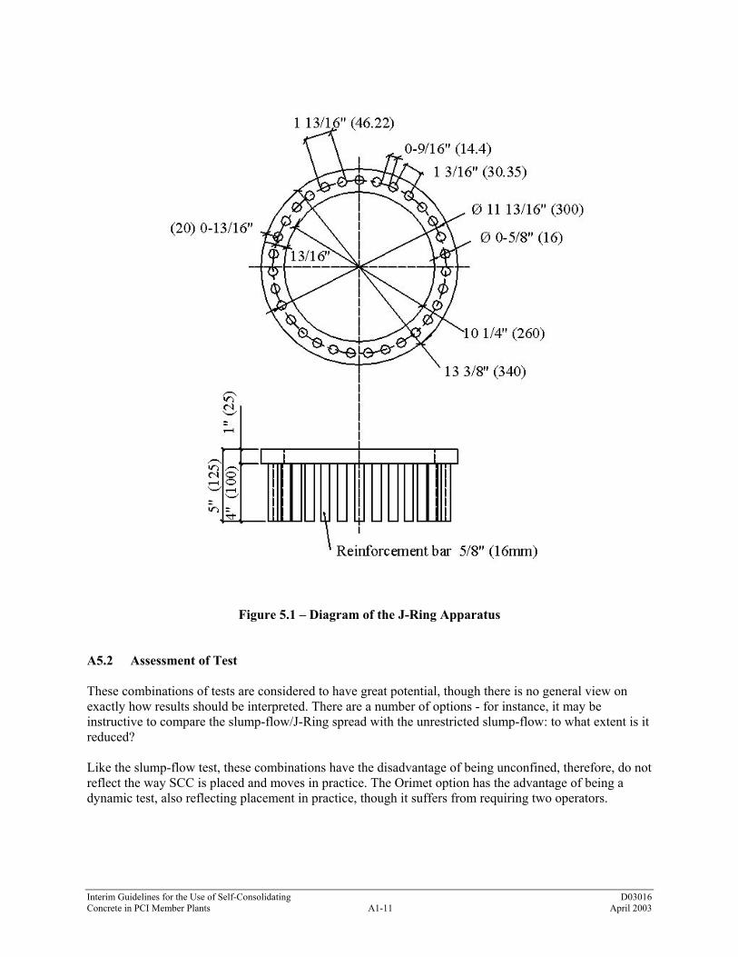
Interim Guidelines for the Use of Self-Consolidating D03016 Concrete in PCI Member Plants A1-11 April 2003
Figure 5.1 – Diagram of the J-Ring Apparatus A5.2 Assessment of Test These combinations of tests are considered to have great potential, though there is no general view on exactly how results should be interpreted. There are a number of options - for instance, it may be instructive to compare the slump-flow/J-Ring spread with the unrestricted slump-flow: to what extent is it reduced? Like the slump-flow test, these combinations have the disadvantage of being unconfined, therefore, do not reflect the way SCC is placed and moves in practice. The Orimet option has the advantage of being a dynamic test, also reflecting placement in practice, though it suffers from requiring two operators.

Interim Guidelines for the Use of Self-Consolidating D03016 Concrete in PCI Member Plants A1-12 April 2003
A5.3 Equipment a. Mold, WITHOUT foot pieces, in the shape of a truncated cone with the internal dimensions 8-inch
diameter (200 mm) at the base, 4-inch diameter (100 mm) at the top, and a height of 12 inches (300 mm)
b. Base plate of a stiff non-absorbing material, at least 28 inches (700 mm) square, marked with a
circle marking the central location for the slump cone, and a further concentric circle of 20 inches (500 mm) diameter
c. Trowel d. Scoop e. Ruler f. J-Ring, a rectangular section 1-1/8- by 1-inch (30 by 25 mm) open steel circular ring, drilled
vertically with holes In the holes, can be screwed threaded sections of reinforcement bar (length 4 inches (100 mm), diameter 3/8 inch (9 mm), and spacing 1-7/8 ± 1/8 inch (48 ±2 mm). A5.4 Procedure a. About 0.2 ft3 (6 L) of SCC is needed to perform the test, sampled normally. b. Moisten the base plate and inside of slump cone. c. Place base plate on level stable ground. d. Place the J-Ring centrally on the base plate with the slump-cone centrally inside it and hold down
firmly. e. Fill the cone with the scoop. Do not tamp, simply strike off the SCC level with the top of the cone
with the trowel. f. Remove any surplus SCC from around the base of the cone. g. Raise the cone vertically and allow the SCC to flow out freely. h. Measure the final diameter of the SCC in two perpendicular directions. i. Calculate the average of the two measured diameters (inch or mm). j. Measure the difference in height between the SCC just inside the bars and that just outside the bars. k. Calculate the average of the difference in height at four locations expressed in millimeters. l. Note any border of mortar or cement paste without coarse aggregate at the edge of the pool of SCC.

Interim Guidelines for the Use of Self-Consolidating D03016 Concrete in PCI Member Plants A1-13 April 2003
Calculation of J-Ring Value (refer to Figure 5.2) a. Measure the value d1 in the center of the J-Ring and also 4 values da and db just inside and just
outside the ring (measurements in mm). b. Calculate h1 = 125 – d1 and all h values hax = 125 – dax (x = 1 to 4) c. Calculate 4 values h1 – hax; calculate median value h1m – ham d. Calculate 4 values hax – hbx; calculate median value ham – hbm e. Calculate 2(ham – hbm) – (h1m – ham). This is the J-Ring test value.
Figure 5.2 – Diagram of the J-Ring Apparatus A5.5 Interpretation of the Test Results In general, greater J-Ring spread flow results in greater passing ability. Satisfactory passing ability without blockage is attained when the value 2(ham – hbm) – (h1m – ham) is less than 15 mm ~ 0.59 inch. Generally acceptable passing ability is achieved when this value is around 10 mm ~ 0.39 inch.
db2
hb2 ha2 h1 ha4 hb4
db4
1"
da4d1da2
D
Concrete
hb2 ha2 h1 ha4 hb4
ha3
ha1
hb1
hb3
Interim Guidelines for the Use of Self-Consolidating D03016 Concrete in PCI Member Plants A1-14 April 2003
A6.0 J-RING IN CONJUNCTION WITH THE ORIMET TEST METHOD A6.1 Introduction See above for comments about using J Ring and Orimet tests together. A6.2 Assessment of Test See above for comments about using J-Ring and Orimet tests together. A6.3 Equipment a. Orimet device of a stiff non absorbing material, see Figure 12.1 b. Trowel c. Scoop d. Stopwatch e. Ruler f. J-Ring, a rectangular section 1-1/8- by 1-inch (30 by 25 mm) open circular steel ring, drilled
vertically with holes. In the holes of the J-Ring, can be screwed threaded sections of reinforcement bar (length 4 inches (100 mm), diameter 3/8 inch (10 mm), and spacing 1-7/8 ± 1/8 inch (48 ±2 mm). A6.4 Procedure a. About 8 liters of SCC is needed to perform the test, sampled normally. b. Set the Orimet on firm ground. c. Moisten the inside surfaces of the casting pipe and the orifice. d. Keep the trap door open to allow any surplus water to drain. e. Close the trap door and place the J-Ring centered beneath the Orimet orifice. f. Fill the apparatus completely with SCC without compacting or tapping, simply strike off the SCC
level with the top with the trowel. g. Open the trap door and allow the SCC to flow out under gravity. h. Simultaneously, start the stopwatch and record the time. i. Start the stopwatch when the trap door is opened, and record the time for the discharge to complete
(the flow time). This is taken to be when light is seen from above through the orifice section. j. Measure the final diameter of the SCC in two perpendicular directions.

Interim Guidelines for the Use of Self-Consolidating D03016 Concrete in PCI Member Plants A1-15 April 2003
k. Calculate the average of the two measured diameters (inch or mm). l. Measure the difference in height between the SCC just inside the bars and that just outside the bars
as described in A5.0. m. Calculate the average of the difference in height at four locations (inch or mm). n. Note any border of mortar or cement paste without coarse aggregate at the edge of the pool of SCC. o. The whole test has to be performed within 5 minutes. A6.5 Interpretation of Result It should be appreciated that although these combinations of tests measure flow and passing ability, the results are not independent. The measured flow is certainly affected by the degree to which the SCC movement is blocked by the reinforcing bars. The extent of blocking is much less affected by the flow characteristics, and we can say that clearly, the greater the difference in height inside the J-Ring and outside of it, the less the passing ability of the SCC. Blocking and/or segregation can also be detected visually, often more reliably than by calculation.

Interim Guidelines for the Use of Self-Consolidating D03016 Concrete in PCI Member Plants A1-16 April 2003
A7.0 V-FUNNEL TEST AND V-FUNNEL TEST AT T = 5 MINUTES A7.1 Introduction The equipment consists of a V-shaped funnel, shown in Figure 7.1. An alternative type of V-funnel, the O-Funnel, with a circular section, is also used in Japan but is not described in this test method. The described V-Funnel test is used to determine the filling ability (flowability) of the SCC with a maximum aggregate size of 20 mm (3/4 inch). The funnel is filled with about 12 liters of SCC and the time taken for it to flow through the apparatus measured. After this, the funnel can be refilled with SCC and left for 5 minutes to settle. If the SCC shows segregation, then the flow time will increase significantly. If the SCC mixture has thixotropic properties, it will also indicate an increased flow time. A7.2 Assessment of Test Though the test is designed to measure flowability, the result is affected by SCC properties other than flow. The inverted cone shape will cause any tendency of the SCC to block to be reflected in the result - if, for example there is too much coarse aggregate. High flow time can also be associated with low deformability due to a high paste viscosity, and with high interparticle friction. While the apparatus is simple, the effect of the angle of the funnel and the wall effect on the flow of SCC is not clear.
Figure 7.1 – V-Funnel Apparatus
A7.3 Equipment a. V-Funnel b. Bucket (± 0.4 ft3, ± 12 liters) c. Trowel d. Scoop e. Stopwatch

Interim Guidelines for the Use of Self-Consolidating D03016 Concrete in PCI Member Plants A1-17 April 2003
A7.4 Procedure Flow Time a. About 0.4 ft3 (12 L) of SCC is needed to perform the test, sampled normally. b. Set the V-Funnel on firm ground. c. Moisten the inside surfaces of the funnel. d. Keep the trap door open to allow any surplus water to drain. e. Close the trap door and place a bucket underneath. f. Fill the apparatus completely with SCC without compacting or tapping, simply strike off the SCC
level with the top with the trowel. g. Open the trap door within 10 seconds after filling and allow the SCC to flow out under gravity. h. Start the stopwatch when the trap door is opened, and record the time for the discharge to complete
(the flow time). This is taken to be when light is seen from above through the funnel. i. The whole test has to be performed within 5 minutes. A7.5 Procedure Flow Time at T-5 Minutes a. Performed subsequent to the flow time test. b. Do NOT clean or moisten the inside surfaces of the funnel again. c. Close the trap door and refill the V-Funnel immediately after measuring the flow time. d. Fill the apparatus completely with SCC without compacting or tapping, simply strike off the SCC
level with the top with the trowel. e. Place a bucket underneath. f. Open the trap door 5 minutes after the second fill of the funnel and allow the SCC to flow out under
gravity g. Simultaneously start the stopwatch when the trap door is opened, and record the time for the
discharge to complete (the flow time at T-5 minutes). The record time is to be when light is seen from above through the funnel.
A7.6 Interpretation of Result This test measures the ease of flow of the SCC; shorter flow times indicate greater flowability. The inverted cone shape restricts flow, and prolonged flow times may give some indication of the susceptibility of the mix to blocking. After 5 minutes of settling, segregation of SCC (if any) will cause the flow time to increase. As noted above, the flow time will also increase if the SCC has thixotropic properties.

Interim Guidelines for the Use of Self-Consolidating D03016 Concrete in PCI Member Plants A1-18 April 2003
A8.0 L-BOX TEST METHOD A8.1 Introduction This test, based on a Japanese design to evaluate underwater SCC, has been described by Petersson (Reference 2, page 80). The test assesses the flow of the SCC, and also the extent to which it is subject to blocking by reinforcement. The apparatus is shown in Figure 8.1. The apparatus consists of a rectangular-section box in the shape of an ‘L’, with a vertical and horizontal section, separated by a moveable gate, in front of which vertical lengths of reinforcement bar are fitted. The vertical section is filled with SCC, and then the gate lifted to let the SCC flow into the horizontal section. When the flow has stopped, the height of the SCC at the end of the horizontal section is expressed as a proportion of that remaining in the vertical section (H2/Hl in the diagram). It indicates the slope of the SCC when at rest. This is an indication passing ability, or the degree to which the passage of SCC through the bars is restricted. The horizontal section of the box can be marked at 8 inches (200 mm) and 16 inches (400 mm) from the gate and the times taken to reach these points measured. These are known as the T-20 and T-40 times and are an indication for the filling ability. The sections of reinforcing bar can be of different diameters and spaced at different intervals: in accordance with normal reinforcement considerations, three times the maximum aggregate size might be appropriate. The bars can be set at any spacing to impose a more or less severe test of the passing ability of the SCC. A8.2 Assessment of Test This is a widely used test, suitable for laboratory, and perhaps site use. It assesses filling and passing ability of SCC, and serious lack of stability (segregation) can be detected visually. If the apparatus is designed for disassembly after the concrete is allowed to harden, segregation may also be detected by subsequently sawing and inspecting sections of the SCC in the horizontal section. There is no evidence of what effect the wall of the apparatus and the consequent 'wall effect' might have on the SCC flow, but this arrangement does, to some extent, replicate what happens to SCC on site when it is confined within formwork. Two operators are preferred if times are measured, and a degree of operator error is inevitable. A8.3 Equipment a. L-Box of a stiff non-absorbing material, see Figure 8.1 b. Trowel c. Scoop d. Stopwatch

Interim Guidelines for the Use of Self-Consolidating D03016 Concrete in PCI Member Plants A1-19 April 2003
Figure 8.1 – L-Box Test Apparatus A8.4 Procedure a. About 0.5 ft3 (14 L) of SCC is needed to perform the test, sampled normally. b. Set the apparatus level on firm ground, ensure that the sliding gate can open freely and then close it. c. Moisten the inside surfaces of the apparatus, remove any surplus water. d. Fill the vertical section of the apparatus with the SCC sample. e. Leave it to stand for approximately 1 minute. f. Lift the sliding gate and allow the SCC to flow out into the horizontal section. g. Simultaneously, start the stopwatch and record the times taken for the SCC to reach the 8-inch
(200 mm) and 16-inch (400 mm) marks. h. When the SCC stops flowing, the dimensions “H1” and “H2” are measured. i. Calculate H2/H1, the blocking ratio. j. The whole test has to be performed within 5 minutes. A8.5 Interpretation of Result If the SCC flows as freely as water, at rest, it will be horizontal, so H1 / H2 = 1. Therefore, the nearer this test value, the 'blocking ratio,' is to 1.0, the better the flow of the SCC. Obvious blocking of coarse aggregate behind the reinforcing bars can be detected visually.
7 7/8" (200) 4" (100)
23
5/8"
(600
)
H 1
7 7/8" (200)15 3/4" (400)
31 1/2" (800)
H 2
5 7/
8" (1
50)
Rebar 3 - #4 With Gap Of 1 3/8" (35) Between

Interim Guidelines for the Use of Self-Consolidating D03016 Concrete in PCI Member Plants A1-20 April 2003
A9.0 U-BOX TEST METHOD A9.1 Introduction Sometimes the apparatus is called a "box-shaped" test. The test is used to measure the filling ability of SCC. The apparatus consists of a vessel that is divided by a middle wall into two compartments, shown by R1 and R2 in Figure 9.1 below.
Bars spaced at 50 mm on center
Figure 9.1 – European U-Box Apparatus An opening with a sliding gate is fitted between the two sections. Reinforcing bars with nominal diameters of 1/2 inch (13 mm) are installed at the gate with center-to-center spacing of 2 inches (50 mm). This creates a clear spacing of 1-3/8 inches (35 mm) between the bars. The left-hand section is filled with about 0.67 ft3 (20 L) of SCC then the gate lifted and SCC flows upwards into the other section. The height of the SCC in the second section is measured. Note: An alternative design of box to this, but built on the same principle, is recommended by the Japan Society of Civil Engineers. See Figure 9.2.

Interim Guidelines for the Use of Self-Consolidating D03016 Concrete in PCI Member Plants A1-21 April 2003
Figure 9.2 – Japanese U-Box Apparatus

Interim Guidelines for the Use of Self-Consolidating D03016 Concrete in PCI Member Plants A1-22 April 2003
A9.2 Assessment of Test This is a simple test to conduct, but the equipment is more difficult to construct. It provides a good direct assessment of filling ability - this is literally what the SCC has to do - modified by an unmeasured requirement for passing ability. The 1-3/8-inch (35 mm) gap between the sections of reinforcement may be considered too close. A filling height of 300 mm (11-7/8 inches) qualifies as SCC. The question remains open of what filling height less than 300 mm (11-7/8 inches) is still acceptable. A9.3 Equipment a. The filling apparatus shall be a U-shaped container of the dimensions shown in Figure 9.1 or 9.2
and made of material with a slippery surface and of sufficient rigidity. b. In the center of the filling apparatus, steel deformed rebars shown in Figure 9.1 or 9.2 are
arranged in a grid to disturb the concrete flow. c. The apparatus shall have a groove in its center where a barrier board and a shutter gate can be
installed to separate compartments A and B. d. To measure the amount of coarse aggregate in the concrete after passing through the following
barrier, a shutter gate for sampling, shown in Figure 9.2 is attached in the B compartment near the flow barrier.
e. In addition to the filling apparatus, prepare
1. pouring container (a 5-liter bucket) 2. straight edge for leveling the SCC 3. measurement tape 4. stopwatch 5. wet cloth
Note: The insides of the container must be smooth so that abrasion resistance between the concrete and the container can be minimized. Any material can be used for the container, but transparent material is recommended because it will permit observation of the flowing conditions inside the U-box. There are two types of flow barriers. One barrier has five D10 (3/8-inch diameter) deformed bars and the second type has three D13 (1/2-inch diameter) deformed bars. The appropriate barrier should be selected depending on the shape, size, and the arrangement of steel in the target structure. Using high-fluidity concrete and assuming that there is no abrasion resistance between the concrete and the inside walls of the container, the height of the concrete in B compartment when A and B compartments are balanced is calculated to be 295 mm (11.6 inches) in the container shown in Figure 9.1 and 340 mm (13.4 inches) in the container shown in Figure 9.2. (Note Table 3.4.2 and the U-Box rankings discussed in 3.2.3 refer to the apparatus shown in Figure 9.1.) Usually the measurement of the amount of coarse aggregate in the mixture after passing the flow barrier is not conducted. However, if a more precise evaluation of the passing ability through barriers by auto-filling is required, determine the aggregate amount that passes through the barrier.

Interim Guidelines for the Use of Self-Consolidating D03016 Concrete in PCI Member Plants A1-23 April 2003
A9.4 Procedure a. About 0.67ft3 (20L) of SCC is needed to perform the test, sampled normally. b. Set the apparatus level on firm ground, ensure that the sliding gate can open freely and then close it. c. Moisten the inside surfaces of the apparatus, remove any surplus water. d. Fill the one compartment of the apparatus with the SCC sample. e. Leave it to stand for approximately 1 minute. f. Lift the sliding gate and allow the SCC to flow out into the other compartment. g. When the SCC stops flowing, the heights “R1” and “R2” in both compartments are measured. h. Record filling height (R2). i. Calculate R1-R2, record. j. The whole test has to be performed within 5 minutes. A9.5 Interpretation of Result If the SCC flows as freely as water, at rest, it will be horizontal, so H1-H2 = 0. Therefore, the nearer this test value, the 'filling height,' is to zero, the better the flow of the SCC. The U-Box ranking for use in Table 3.4.2 is established as indicated in Section 3.2.3(c).

Interim Guidelines for the Use of Self-Consolidating D03016 Concrete in PCI Member Plants A1-24 April 2003
A10.0 FILLING VESSEL TEST METHOD (ALSO KNOWN AS KAJIMA BOX METHOD) A10.1 Introduction The test is used to measure the filling ability of SCC with a maximum aggregate size of 3/4 inch (20 mm). The apparatus consists of a container (transparent Plexiglas) with a flat and smooth surface. In the container are 35 obstacles made of PVC with a diameter of 3/4 inch (20 mm) and a distance center to center of 2 inches (50 mm). A filling pipe is located at the top of the apparatus. The pipe has a diameter of 4 inches (100 mm), a height 20 inches (500 mm), with a funnel height of 4 inches (100 mm). The container is filled with SCC through this filling pipe and the difference in height between two sides of the container is a measure of the filling ability. A10.2 Assessment of Test This is a test that is difficult to perform on site due to the complex structure of the apparatus and large weight of the SCC (see Figure 10.1). It gives a good impression of the self-consolidating characteristics of the SCC. Even a SCC mix with a high-filling ability will perform poorly if the passing ability and segregation resistance are poor. A10.3 Equipment a. Fill box of a stiff, transparent, non-absorbing material b. Scoop (64 oz - 1.5 to 2 liters) c. Ruler d. Stopwatch A10.4 Procedure a. About 1.5 ft3 (45 L) of SCC is needed to perform the test, sampled normally. b. Set the apparatus level on firm ground. c. Moisten the inside surfaces of the apparatus, remove any surplus water. d. Fill the apparatus with the SCC sample. e. Pour the concrete through the funnel at a constant rate of 0.2 liter per second. f. Stop pouring when the concrete reaches a level of 220 mm (8-5/8 inches) in the nonreinforced
section of the vessel. g. Measure the A surface and determine the cross-sectional area of Area A. h. Calculate the filling capacity A/(A+B) ratio. i. The whole test has to be performed within 8 minutes.

Interim Guidelines for the Use of Self-Consolidating D03016 Concrete in PCI Member Plants A1-25 April 2003
Figure 10.1 – Filling Vessel Test Apparatus A10.5 Interpretation of result If the SCC flows as freely as water, at rest, it will be horizontal, so average filling percentage = 100 percent. Therefore, the nearer this test value, the 'filling height,' is to 100 percent, the better the filling ability characteristics of the SCC.
150 mm 7 x 50 = 350 mm
d = 16 mm
300 mm 250 mm
300 mm
AB
Concrete
Filling capacity (%) = A/(A+B)
Interim Guidelines for the Use of Self-Consolidating D03016 Concrete in PCI Member Plants A1-26 April 2003
A11.0 GTM SCREEN STABILITY TEST METHOD A11.1 Introduction This test has been developed to assess segregation resistance (stability). It consists of taking a sample of 0.375ft3 (10 L) of SCC, allowing it to stand for a period to allow any internal segregation to occur, then pouring half of it on to a 1/4-inch (5 mm) sieve of 14-inch diameter (350 mm), which stands on a sieve pan on a weigh scale. After 2 minutes, the mortar that passed through the sieve is weighed, and expressed as a percentage of the weight of the original sample on the sieve. A11.2 Assessment of Test Practicing engineers who have used this test say it is a very effective way of assessing the stability of SCC. However, though simple, it is not a rapid test, and requires an accurate weigh-scale, so it may not be suitable for site use. The repeatability of results may be questionable. A11.3 Equipment a. 0.375 ft3 (10 L) bucket with lid b. 1/4-inch (5 mm) sieve, 14-inch (350 mm) diameter c. Sieve pan d. Balance, accuracy 0.5-pound (20g), minimum capacity 50 pounds (20kg) e. Stopwatch A11.4 Procedure a. About 0.375 ft3 (10 L) of SCC is needed to perform the test, sampled normally. b. Allow the SCC in the bucket to stand for 15 minutes covered with a lid to prevent evaporation. c. Determine the mass of the empty sieve pan. d. Inspect the surface of the SCC, and if there is any bleeding, water and note it. e. Pour the top 0.07 ft3 (2 L) or approximately 10.5 lb ±0.5 lb (4.8kg ±0.2kg) only of the SCC sample
within the bucket, into a pouring container. f. Determine the mass of the filled pouring container. g. Pour all the SCC from the pouring container onto the sieve from a height of 20 inches (500 mm) in
one smooth continuous movement. h. Weigh the empty pouring container. i. Calculate mass of SCC poured onto sieve, Ma. (i.e., the difference between the weights full and
empty). j. Allow the mortar fraction of the sample to flow through the sieve into the sieve pan for a period of
2 minutes.

Interim Guidelines for the Use of Self-Consolidating D03016 Concrete in PCI Member Plants A1-27 April 2003
k. Remove sieve and determine mass of the filled sieve pan. Calculate mass of sample passing sieve, Mb, by subtracting the empty sieve pan mass from the filled sieve pan mass.
l. Calculate the percentage of the sample passing the sieve, the segregation ratio: (Mb/Ma) x 100. A11.5 Interpretation of Result Empirical observations suggest that if the percentage of mortar that has passed through the sieve, the segregation ratio, is between 5 and 15 percent of the weight of the sample, the segregation resistance is considered satisfactory. Below 5 percent, the resistance is excessive, and likely to affect the surface finish (blow holes likely). Above 15 percent, and particularly above 30 percent, there is strong likelihood of segregation.

Interim Guidelines for the Use of Self-Consolidating D03016 Concrete in PCI Member Plants A1-28 April 2003
A12.0 ORIMET TEST METHOD A12.1 Introduction The Orimet was developed as a method for assessment of highly workable, flowing fresh SCC mixes on construction sites. The equipment is shown in Figure 12.1. The test is based on the principle of an orifice rheometer. The Orimet consists of a vertical casting pipe fitted with a changeable inverted cone-shaped orifice at its lower, discharge end, with a quick-release trap door to close the orifice. Usually the orifice has a 3-1/4-inch (80 mm) internal diameter, which is appropriate for assessment of SCC mixes of aggregate size not exceeding 3/4 inch (20 mm). Orifices of other sizes, usually from 2-3/4 inches (70 mm) to 3-5/8 inches (90 mm) in diameter, can be fitted instead. Operation consists simply of filling the Orimet with SCC, then opening the trapdoor and measuring the time taken for light to appear at the bottom of the pipe (when viewed from above). A12.2 Assessment of Test This test is able to simulate the flow of fresh SCC during actual placing on sites. It is a rapid test, and the equipment is simple and easily maintained. The test has the useful characteristic of being capable of differentiation between highly workable, flowing mixes; and might, therefore, be useful for compliance testing of successive loads on site. The timing procedure, however, may be subject to error, and ideally requires two people. A12.3 Equipment a. Orimet device of a stiff non-absorbing material, see Figure 10.1 b. Bucket (± 0.375 ft3, ±10 liters) c. Trowel d. Scoop e. Stopwatch
Figure 12.1 – Orimet Test Apparatus
43"
(1,0
90)
23 5
/8" (
600)
2 3/
8" (6
0)

Interim Guidelines for the Use of Self-Consolidating D03016 Concrete in PCI Member Plants A1-29 April 2003
A12.4 Procedure a. About 0.26ft3 (8 L) of SCC is needed to perform the test, sampled normally. b. Set the Orimet on firm ground. c. Moisten the inside surfaces of the casting pipe and the orifice. d. Keep the trap door open to allow any surplus water to drain. e. Close the trap door and place a bucket underneath. f. Fill the apparatus completely with SCC without compacting or tapping, simply strike off the SCC
level with the top with the trowel. g. Open the trap door and allow the SCC to flow out under gravity. h. Start the stopwatch when the trap door is opened, and record the time for the discharge to complete
(the flow time). This is taken to be when light is seen from above through the orifice section. i. The whole test has to be performed within 5 minutes. A12.5 Interpretation of Result This test measures the ease of flow of the SCC; shorter flow times indicate greater flowability. For SCC, a flow time of 5 seconds or less is considered appropriate. The inverted cone shape at the orifice restricts flow, and prolonged flow times may give some indication of the susceptibility of the mix to blocking and/or segregation.

Interim Guidelines for the Use of Self-Consolidating D03016 Concrete in PCI Member Plants A1-30 April 2003
A13.0 VISUAL STABILITY INDEX (VSI) RATING TEST METHOD From: Daczko, Joseph A., Kurtz, Mark A., “Development of High-Volume Coarse Aggregate Self-Compacting Concrete,” Proceedings of the Second International Symposium on Self-Compacting Concrete, October 23-25, 2001, Tokyo, Japan A13.1 Introduction This method involves the visual evaluation of the SCC patty resulting from observation of the SCC just prior to placement and after the performance of the slump flow test. It is used to evaluate the relative stability of batches of the same or similar SCC mixes. The VSI test is most applicable to SCC mixes that tend to bleed. If a mix does not bleed, this test is less useful in identifying a mix’s tendency to segregate. A13.2 Assessment of Test This test requires the development of considerable judgment in the individual making the VSI assessment. The subjectivity of this test method must be overcome by experience of the individual making the VSI assessment. The VSI assessor should have experience evaluating SCC mixes that are both successful and those are not successful. A13.3 Equipment Good light and the equipment needed to perform the slump flow test is needed. Supplemental lighting to view the interior of the mixing drum should be provided. A13.4 Procedure The procedure is a visual assessment of the SCC. Refer to photographs of SCC patty comprising the range of VSI ratings on the following pages. A VSI rating = 0 indicated no evidence of segregation in the slump flow patty, in the mixer drum, or in the sampling wheelbarrow. A VSI rating = 0.5 indicates no mortar halo or aggregate pile in the slump flow patty, but very slight evidence of bleed or air popping on the surface of the SCC in the mixer drum or sampling wheelbarrow. A VSI rating = 1 indicates no mortar halo or aggregate pile in the slump flow patty but some slight bleed or air popping on the surface of the SCC in the mixer drum or sampling wheelbarrow. A VSI rating = 1.5 indicates just noticeable mortar halo and/or a just noticeable aggregate pile in the slump flow patty and noticeable bleeding in the mixer drum and sampling wheelbarrow. A VSI rating = 2 indicates a slight mortar halo (<10 mm) (<0.4 inch) and/or aggregate pile in the slump flow patty and highly noticeable bleeding in the mixer drum and sampling wheelbarrow. A VSI rating = 3 indicates clearly segregating by evidence of a large mortar halo (>10 mm) (>0.4 inch) and/or large aggregate pile in the center of the SCC patty and a thick layer of paste on the surface of the resting SCC in the mixer drum or sampling wheelbarrow.

Interim Guidelines for the Use of Self-Consolidating D03016 Concrete in PCI Member Plants A1-31 April 2003
A13.5 Interpretation of result VSI ratings of 2 or 3 should lead to some action in the adjustment of the SCC mix. The production qualification testing should define rejection limits for SCC batches. The results of the VSI test should form a part of the definition of rejection limits.

Interim Guidelines for the Use of Self-Consolidating D03016 Concrete in PCI Member Plants A1-32 April 2003
VSI = 0
VSI = 0

Interim Guidelines for the Use of Self-Consolidating D03016 Concrete in PCI Member Plants A1-33 April 2003
VSI = 0
VSI = 0

Interim Guidelines for the Use of Self-Consolidating D03016 Concrete in PCI Member Plants A1-34 April 2003
VSI = 0
VSI = 0

Interim Guidelines for the Use of Self-Consolidating D03016 Concrete in PCI Member Plants A1-35 April 2003
VSI = 0
VSI = 0

Interim Guidelines for the Use of Self-Consolidating D03016 Concrete in PCI Member Plants A1-36 April 2003
VSI = 0.5
VSI = 0.5
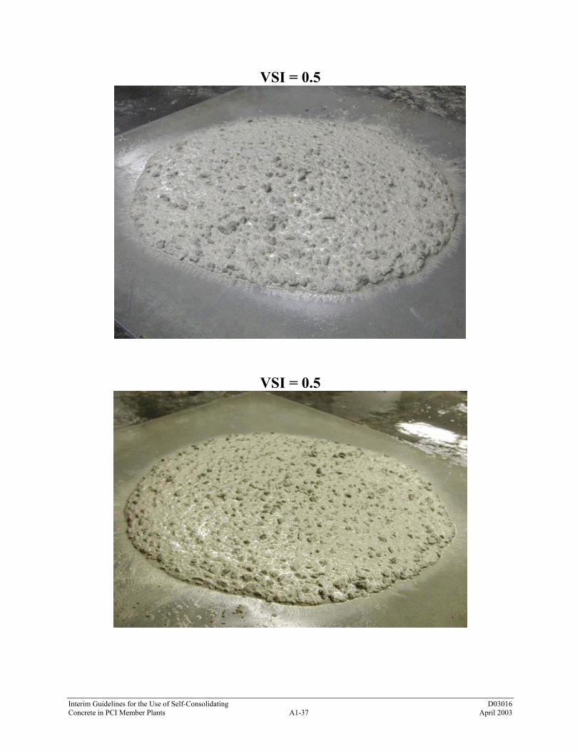
Interim Guidelines for the Use of Self-Consolidating D03016 Concrete in PCI Member Plants A1-37 April 2003
VSI = 0.5
VSI = 0.5

Interim Guidelines for the Use of Self-Consolidating D03016 Concrete in PCI Member Plants A1-38 April 2003
VSI = 0.5
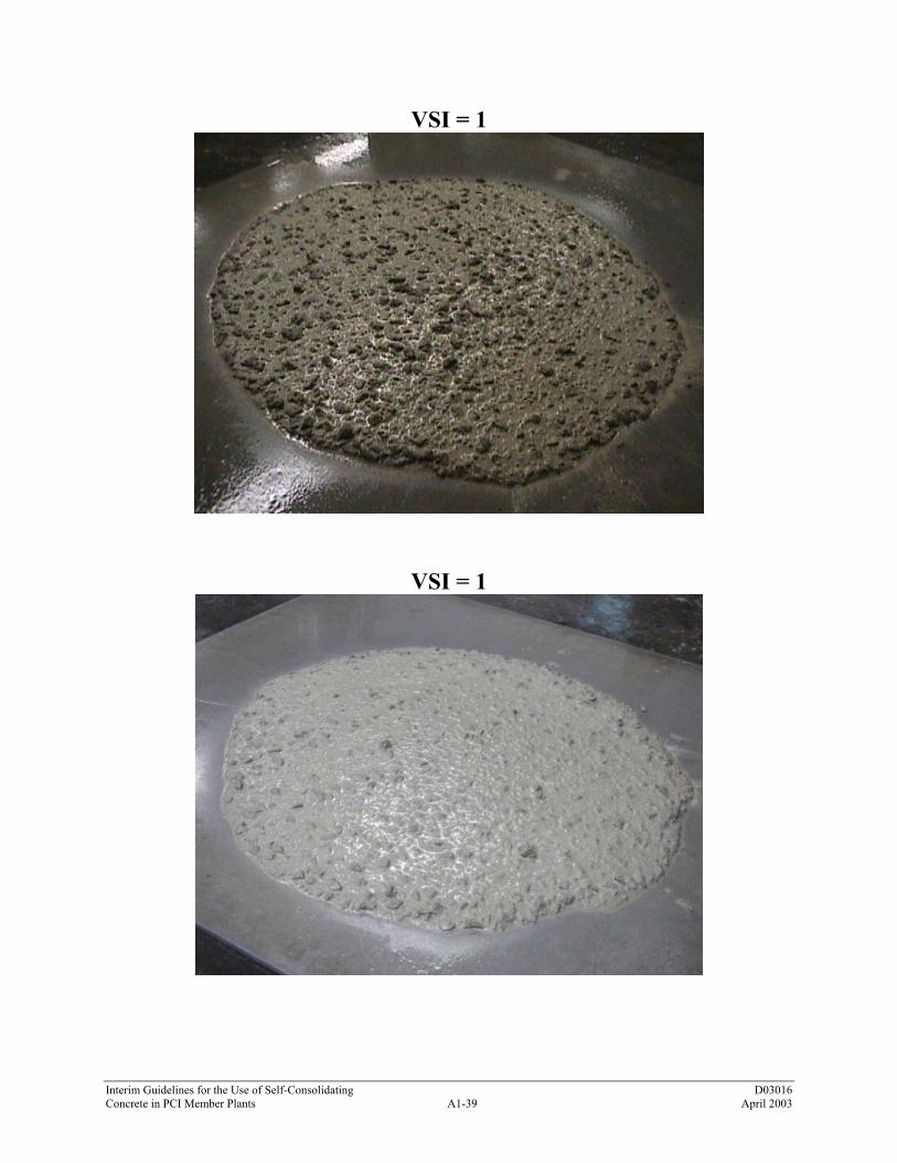
Interim Guidelines for the Use of Self-Consolidating D03016 Concrete in PCI Member Plants A1-39 April 2003
VSI = 1
VSI = 1

Interim Guidelines for the Use of Self-Consolidating D03016 Concrete in PCI Member Plants A1-40 April 2003
VSI = 1
VSI = 1
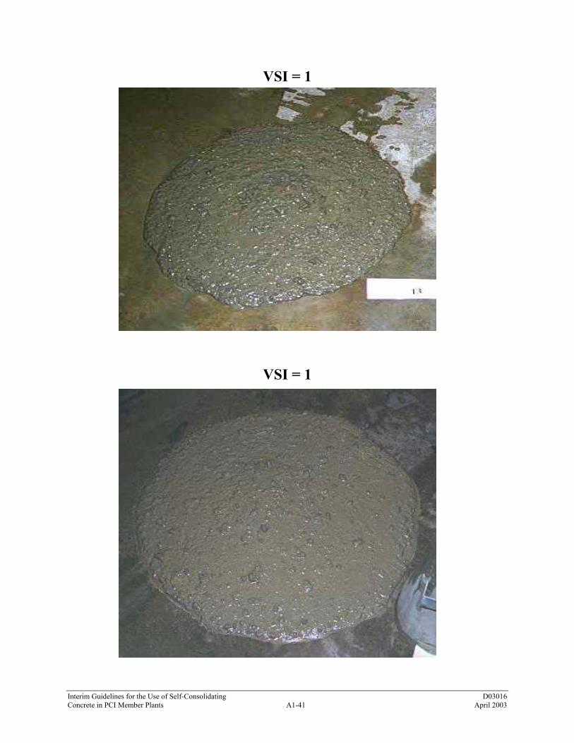
Interim Guidelines for the Use of Self-Consolidating D03016 Concrete in PCI Member Plants A1-41 April 2003
VSI = 1
VSI = 1
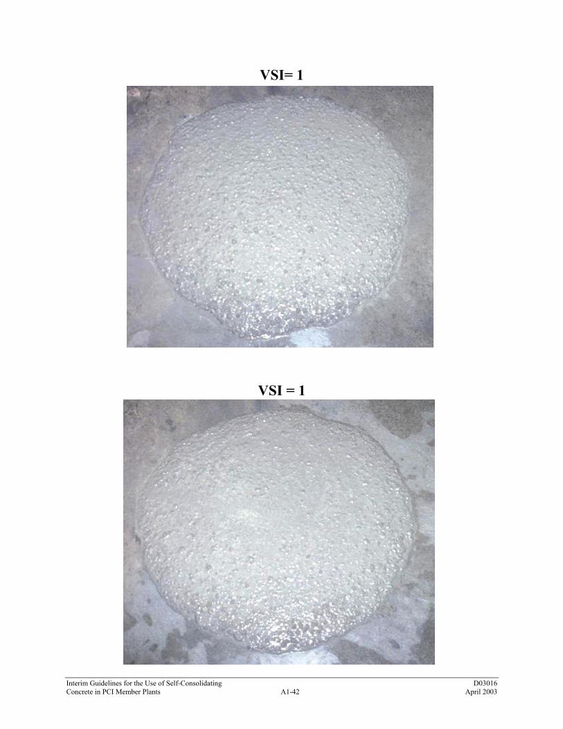
Interim Guidelines for the Use of Self-Consolidating D03016 Concrete in PCI Member Plants A1-42 April 2003
VSI= 1
VSI = 1

Interim Guidelines for the Use of Self-Consolidating D03016 Concrete in PCI Member Plants A1-43 April 2003
VSI = 1.5
VSI = 1.5

Interim Guidelines for the Use of Self-Consolidating D03016 Concrete in PCI Member Plants A1-44 April 2003
VSI = 1.5
VSI = 1.5

Interim Guidelines for the Use of Self-Consolidating D03016 Concrete in PCI Member Plants A1-45 April 2003
VSI = 2
VSI = 2
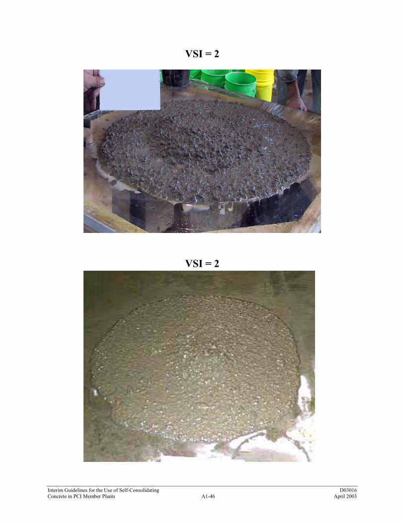
Interim Guidelines for the Use of Self-Consolidating D03016 Concrete in PCI Member Plants A1-46 April 2003
VSI = 2
VSI = 2
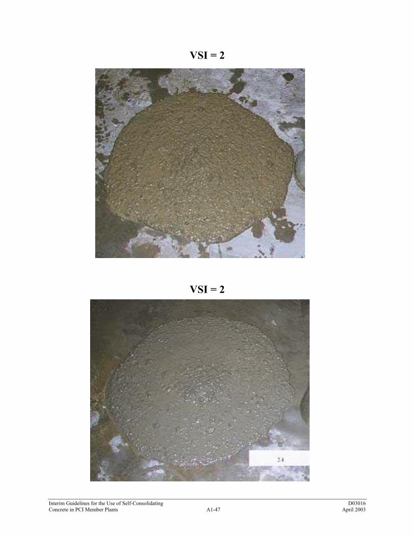
Interim Guidelines for the Use of Self-Consolidating D03016 Concrete in PCI Member Plants A1-47 April 2003
VSI = 2
VSI = 2

Interim Guidelines for the Use of Self-Consolidating D03016 Concrete in PCI Member Plants A1-48 April 2003
VSI = 2

Interim Guidelines for the Use of Self-Consolidating D03016 Concrete in PCI Member Plants A1-49 April 2003
VSI = 3
VSI = 3

Interim Guidelines for the Use of Self-Consolidating D03016 Concrete in PCI Member Plants A1-50 April 2003
A14.0 BLEEDING TEST METHOD (FRENCH) (From BETONS AUTO-PLACANTS Recommendations) by Association Francaise de Genie Civil A14.1 Introduction This methodology was developed and used experimentally in the Calibe pumping project. A14.2 Assessment of Test The water that bleeds from the SCC sample is released into the perchlorethylene. As the water is less dense than perchlorethylene, it rises to the surface in the graduated column of the test device where its volume can be measured.
Figure 14.1 – Bleed Test Apparatus A14.3 Equipment a. A volumetric SCC air indicator (French NF P 18-353). Note that some commercial air indicators
have a steel tube inside the transparent graduated column for discharging air in the conventional test. This tube must be removed for the bleeding test for it prevents bleed water rising.
b. Perchlorethylene: Perchlorethylene was chosen because of its density – at 1.59 it is heavier than
water – and has a limited health risk. However, it should be used in a well-ventilated area. For more information, read a safety data sheet for the product as there are use restrictions.
c. A tray for standing the air indicator on. d. A funnel and filter paper.

Interim Guidelines for the Use of Self-Consolidating D03016 Concrete in PCI Member Plants A1-51 April 2003
A14.4 Procedure a. Moisten the sides of the air indicator b. Fill the air indicator mold with SCC (record the volume of the SCC sample - generally 5 liters). c. Float off the surface of the SCC. d. Clean the edges of the mold. e. Place the mould on the tray. f. Fit the top part of the testing apparatus and tighten the bolts. g. Fill the apparatus up to the “zero” mark with percholrethylene. h. Close all the valves. i. Record the total level and depth of bleed water on top of the perchlorethylene at 3, 5, 10, 15, 30,
and 60 minutes and after stabilization. j. Open the valves and drain the perchlorethylene into the tray. k. Empty and clean the apparatus. l. Filter the perchlorethylene through the filter paper and into a vessel for reuse. A14.5 Interpretation of Result Plot a curve for the quantity of water on top of the perchlorethylene against time. The first part of this curve is generally linear. The initial bleeding speed is defined by q= V15/t*S Where
q = the bleeding speed (in cm/sec) V15 = the volume of bleed water in the first 15 minutes (in cm3) S= surface area of the SCC sample (in cm2)
T = measuring time (900 sec) Record the total bleed volume (in cm3) obtained at the end of the test.

Interim Guidelines for the Use of Self-Consolidating D03016 Concrete in PCI Member Plants A1-52 April 2003
A15.0 REVISION TO ASTM STANDARD CONCRETE TESTS FOR SCC A15.1 Introduction ASTM standard tests for making SCC test cylinders, SCC test beams, SCC cubes, filling air meters with SCC, filling bleed measuring devices with SCC, etc. can be performed as described in the various ASTM standards, except that SCC samples should not be rodded or vibrated. No hardened specimens shall be made until the slump flow test and VSI test have been completed. If hardened specimens are not taken at the placement location, the sample in the wheelbarrow should be remixed prior to making concrete specimens. The drop height used in the sampling process should not exceed the drop height used in the production placement of the SCC. Sample containers and molds should be filled by scoop from the sampling wheelbarrow and the SCC sample dropped from a height of 6 inches (150 mm) above the mold or container top into the center of the container until the container is filled. When the container is filled, the top surface should be struck off per the ASTM standard procedure. The remainder of the test procedures remain the same as the standard ASTM procedures.

Interim Guidelines for the Use of Self-Consolidating D03016 Concrete in PCI Member Plants A2-1 April 2003
APPENDIX 2 SCC CHECKLIST The checklist is provided to aid specifiers and producers in assuring that all key elements of an SCC application have been considered ahead of the start of precast element production. Property/Action Reference Requirement Completed
MIX CONSTITUENTS Compliance with ASTM 150 Control of the cement type
Cement
Cement amount guide _______ kg/m3 (_______ lbs/yd3)
Compliance with ASTM C33 or ASTM C330 Control of particles smaller than 0.125 mm
(0.005 inch)
Control of moisture content Determination of the sieve curve
Aggregates
Compatibility of coarse aggregate size with space between reinforcement
Mixing Water Compliance with PCI MNL-116-99 Compliance with ASTM C494, ASTM C1017,
ASTM C260
Determination of the types needed and compatibility
Admixtures
Determination of the expected dosage Compliance with ASTM C618, ASTM C989,
ASTM C1240
Determination of the sieve curve Definition of the addition to be used
Powder Additions
Determination of the increase in the water demand
Pigments Compliance with ASTM C979 Raw Materials Definition of all raw materials to be used
MIX COMPOSITION Mix design executed by SCC-experienced
technologist
Coarse aggregate <____% Water to powder ratio =____ to ____ Total powder content _______ kg/m3
(_______ lbs/yd3)
Sand content >___% of the mortar volume Sand <___% of paste volume Sand >___% by weight of total aggregate Total free water < ____ liters (_____ gal)
Mix Design Yield Air Content W/Cm Ratio Maximum mineral additions Unit weight Maximum aggregate size Paste > ___% of the volume of the mix

Interim Guidelines for the Use of Self-Consolidating D03016 Concrete in PCI Member Plants A2-2 April 2003
Property/Action Reference Requirement Completed WORKABILITY TESTS
Slump flow - Abrams _____ to ______ mm ( ____ to ____ in.) T-50 slump flow test _____ to ______ seconds J-Ring test _____ to ______ mm ( ____ to ____ in.) V-Funnel test _____ to ______ seconds V-Funnel T-5 min +____ seconds in addition to V-Funnel test time L-Box test H2/H1= _____ to _____ U-Box test H2 – H1 = _____ mm maximum ( _____ in.) Filling Vessel test _____ to _____% Screen Stability test _____ to _____% Orimet test _____ to _____ seconds
PROPERTIES OF HARDENED CONCRETE Mechanical strength Achieved expected values after 24 hrs, 7 days,
28 days
Shrinkage Meets project specification requirements Modulus of elasticity Achieving the expected values
CONFIRMATION TESTS Filling ability Passing ability Segregation resistance
Full-scale tests
Maintenance of workability > 1 hour

Interim Guidelines for the Use of Self-Consolidating D03016 Concrete in PCI Member Plants A3-1 April 2003
APPENDIX 3 SCC MIX DESIGN EXAMPLES The following procedure by Okazawa is one approach to developing mixes that can be used to efficiently design SCC mixes. The sequence of steps is as follows. a. Designate the desired air content b. Determine the coarse aggregate volume c. Determine the sand content d. Design the paste composition
Note: The example shown is for a mix that does not use a VMA. The design approach when using a VMA would be somewhat different than the example given here. a. Air content can be set in accordance with
Section 2.2.2(f). b. Coarse aggregate volume is defined by bulk
density. Generally coarse aggregate content (material larger than 4 mm [0.16 inch]) should be between 50 and 60 percent.
When the volume of coarse aggregate in SCC
exceeds a certain limit, the opportunity for collision or contact between coarse aggregate particles increases rapidly and there is an increased risk of blockage when the concrete passes through spaces between reinforcement bars.
The lower the maximum aggregate size, the
higher the proportion of coarse aggregate can be.
For rounded aggregates, higher percentage
content can be used than for crushed aggregates.
c. Sand in the context of this composition
procedure is defined as all particles larger than 0.125 mm (0.005 inch) and smaller than 4 mm (0.16 inch). Sand content is defined by bulk density. The optimal volume of content of sand in the mortar varies between 40 to 50 percent, depending on paste properties.
d. Initially, the water powder ratio of zero flow
(βp) is determined in the paste, with the chosen proportion of cement and additions. Flow cone test with water powder ratios by volume of 1.1, 1.2, 1.3, and 1.4 are performed with the selected powder composition. As shown in Figure A3, a line is drawn through the plot of water to powder ratio on the Y axis and relative slump flow on the X axis is plotted. The point where this line intersects, the Y axis is the βp value. This value is used to determine the water demand for new batches of cement and fillers.

Interim Guidelines for the Use of Self-Consolidating D03016 Concrete in PCI Member Plants A3-2 April 2003
e. Determine the optimum water to powder ratio and superplasticizer dosage in mortar
f. Assess the concrete properties by standard tests
e. Tests with flow cone and V-Funnel for mortar are performed at varying water to powder ratios in the range of 0.8 to 0.9 βp and different dosages of superplasticizer. The superplasticizer is used to balance the rheology of the paste. The volume content of sand in the mortar remains the same as determined above.
f. Target values are slump flow of 610 to 660
mm (24 to 26 inches) and V-Funnel time of 7 to 11 seconds.
At target slump flow, if V-Funnel time is
lower than 7 seconds, then decrease the water to powder ratio. For target slump flow and V-Funnel time in excess of 11 seconds, water to powder ratio should be increased.
If these criteria cannot be fulfilled, then the
particular combination of materials is inadequate. A trial with a different superplasticizer is the preferred alternative. Second alternative is a new additive, and as a last resort, a different cement.

Interim Guidelines for the Use of Self-Consolidating D03016 Concrete in PCI Member Plants A3-3 April 2003
Determination of Beta p
5.76
4.243.00
1.92
0.00
0.00
0.20
0.40
0.60
0.80
1.00
1.20
1.40
1.60
0.00 1.00 2.00 3.00 4.00 5.00 6.00 7.00
Relative Slump-flow
Wat
er to
Pow
der R
atio
Value at intercept with Y axis is Beta p
Figure A3 - Determination of the Water to Powder Ratio βp
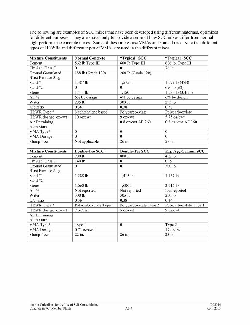
Interim Guidelines for the Use of Self-Consolidating D03016 Concrete in PCI Member Plants A3-4 April 2003
The following are examples of SCC mixes that have been developed using different materials, optimized for different purposes. They are shown only to provide a sense of how SCC mixes differ from normal high-performance concrete mixes. Some of these mixes use VMAs and some do not. Note that different types of HRWRs and different types of VMAs are used in the different mixes. Mixture Constituents Normal Concrete “Typical” SCC “Typical” SCC Cement 562 lb Type III 600 lb Type III 686 lb. Type III Fly Ash Class C 0 0 76 lb Ground Granulated Blast Furnace Slag
188 lb (Grade 120) 200 lb (Grade 120)
Sand #1 1,387 lb 1,575 lb 1,072 lb (47B) Sand #2 0 0 696 lb (#8) Stone 1,441 lb 1,150 lb 1,036 lb (3/4 in.) Air % 6% by design 6% by design 6% by design Water 285 lb 303 lb 293 lb w/c ratio 0.38 0.38 0.38 HRWR Type * Naphtahalene based Polycarboxylate Polycarboxylate HRWR dosage oz/cwt 10 oz/cwt 9 oz/cwt 5.75 oz/cwt Air Entraining Admixture
0.8 oz/cwt AE 260 0.8 oz /cwt AE 260
VMA Type* 0 0 0 VMA Dosage 0 0 0 Slump flow Not applicable 26 in. 28 in. Mixture Constituents Double-Tee SCC Double-Tee SCC Exp Agg Column SCC Cement 700 lb 800 lb 432 lb Fly Ash Class C 140 lb 0 0 lb Ground Granulated Blast Furnace Slag
0 0 300 lb
Sand #1 1,288 lb 1,415 lb 1,157 lb Sand #2 Stone 1,660 lb 1,600 lb 2,015 lb Air % Not reported Not reported Not reported Water 300 lb 305 lb 250 lb w/c ratio 0.36 0.38 0.34 HRWR Type * Polycarboxylate Type 1 Polycarboxylate Type 2 Polycarboxylate Type 1 HRWR dosage oz/cwt 7 oz/cwt 5 oz/cwt 9 oz/cwt Air Entraining Admixture
VMA Type* Type 1 0 Type 2 VMA Dosage 0.75 oz/cwt 17 oz/cwt Slump flow 22 in. 26 in. 23 in.
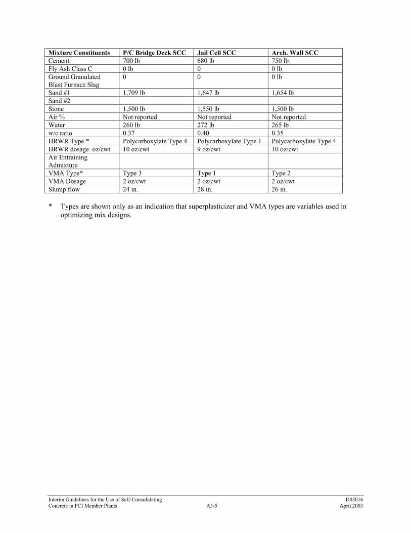
Interim Guidelines for the Use of Self-Consolidating D03016 Concrete in PCI Member Plants A3-5 April 2003
Mixture Constituents P/C Bridge Deck SCC Jail Cell SCC Arch. Wall SCC Cement 700 lb 680 lb 750 lb Fly Ash Class C 0 lb 0 0 lb Ground Granulated Blast Furnace Slag
0 0 0 lb
Sand #1 1,709 lb 1,647 lb 1,654 lb Sand #2 Stone 1,500 lb 1,550 lb 1,500 lb Air % Not reported Not reported Not reported Water 260 lb 272 lb 265 lb w/c ratio 0.37 0.40 0.35 HRWR Type * Polycarboxylate Type 4 Polycarboxylate Type 1 Polycarboxylate Type 4 HRWR dosage oz/cwt 10 oz/cwt 9 oz/cwt 10 oz/cwt Air Entraining Admixture
VMA Type* Type 3 Type 1 Type 2 VMA Dosage 2 oz/cwt 2 oz/cwt 2 oz/cwt Slump flow 24 in. 28 in. 26 in. * Types are shown only as an indication that superplasticizer and VMA types are variables used in
optimizing mix designs.

Interim Guidelines for the Use of Self-Consolidating D03016 Concrete in PCI Member Plants A3-6 April 2003
Interim Guidelines for the Use of Self-Consolidating D03016 Concrete in PCI Member Plants A4-1 April 2003
APPENDIX 4 SOURCES FOR SCC TEST APPARATUS TESTING Bluhm & Feuerherdt GmbH Herstellung und Vertrieb Von Bastoffprufgeraten Geneststrabe 5-6 D-10829 Berlin GERMANY Tel 011-030/755 90 94 – 97 Fax 011-030/755 90 98 www.testing.de e-mail [email protected] See attached sheet from catalog. Has made equipment to Master Builders Specifications Gary Schwartz Olympus Welding 13901 Aspinwall Avenue Cleveland, OH 44110 Tel 216/541-6100 Fax 216/541-6874

Interim Guidelines for the Use of Self-Consolidating D03016 Concrete in PCI Member Plants A4-2 April 2003