resource size, grade and status for personal use only
TRANSCRIPT

http://www.talgaresources.com/irm/PDF/1455/KiskamaIOCGProjectDrillingResultsPage 1
Talga Resources Ltd
ABN 32 138 405 419
1st Floor, 2 Richardson St,
West Perth, WA 6005
T: +61 8 9481 6667
F: +61 8 9322 1935
www.talgaresources.com
Corporate Information
ASX Codes TLG, TLGOA
Shares on issue 181.9m
Options (listed) 44.9m
Options (unlisted) 28.7m
Company Directors
Terry Stinson
Non-Executive Chairman
Mark Thompson
Managing Director
Grant Mooney
Non-Executive Director
Stephen Lowe
Non-Executive Director
ASX:TLG
27 April 2017
Technology minerals company Talga Resources Ltd (“Talga” or the “Company”) (ASX Code: TLG) is pleased to announce an updated JORC Mineral Resource Estimate (“MRE”) of its flagship Nunasvaara graphite deposit (“Nunasvaara”) following diamond drilling and test mining programs in the latter part of 2016. Nunasvaara forms part of Talga’s 100% owned Vittangi Graphite Project (“Vittangi”) located 50km east of Kiruna in northern Sweden.
Highlights of the Talga MRE include:
✓ The global MRE now stands at 12.3Mt @ 25.5%Cg for 3.1Mt of
contained graphite based on a 17%Cg lower cut-off.
• Represents a 25% increase in total resource tonnes and
contained graphite over previous resource of 9.8Mt @ 25.3%Cg
based on a 10%Cg lower cut-off1.
• Maintains position as world’s highest grade graphite mineral
resource2 and reflects progressive growth of deposits with minimal
exploration.
✓ 87% of the global MRE now classified as Indicated.
• Doubles JORC (2012) Indicated tonnage from MRE used in 2014
scoping study3.
• Provides further confidence in quality and consistency of deposit.
• Enables inclusion of additional zones for mining permitting purposes
and economic studies. Provides more flexible development options.
✓MRE includes high grade domain of 2.0Mt @ 32.6% Cg for 652,000t
contained graphite based on a 30%Cg lower cut-off.
• Higher grade zone starts from surface, offering early stage boost to
any development.
✓Mineralisation in MRE present from surface to approximately
220m depth and is open along strike and at depth.
• Provides further increase in scale and development options if
required.
Talga Substantially Increases Flagship Graphite
Resource Size, Grade and Status
Talga Managing Director Mark Thompson commented:
“The updated JORC (2012) - compliant resource for Nunasvaara builds on what is already the world’s
highest grade graphite mineral resource. We have added significant scale, improved grade and boosted
the majority of tonnes into higher status resource categories.
This enables us to extend our planning and development options for this large, high-grade and unique
graphite deposit, on which we have only just scratched the surface. It gives Talga confidence that
additional highly prospective exploration targets already identified in our Vittangi project area have strong
potential to convert to further resources as required to supply future demand growth for both graphite and
graphene products.”
Fo
r pers
onal use
on
ly

http://www.talgaresources.com/irm/PDF/1455/KiskamaIOCGProjectDrillingResultsPage 2
Mineral Resource Overview
The Nunasvaara MRE update was completed by independent geological consultants Oliver Mapeto and Albert Thamm utilising results from diamond drilling completed at the Nunasvaara North prospect (“Nunasvaara North”) in 2016. Nunasvaara North is located ~1,200m to the northeast of the main Nunasvaara graphite deposit (“Nunasvaara South”).
Further details and MRE estimation parameters are provided in Table 1-4, text below and in Appendix 1-2.
Table 1 Global Nunasvaara MRE (17% Cg lower cut-off, April 2017).
Resource Category Tonnes Graphite (% Cg) Contained Graphite (Tonnes)
Indicated 10,700,000 25.7 2,749,900
Inferred 1,600,000 23.9 382,400
Total 12,300,000 25.5 3,136,500
Figure 1 Global JORC/NI43-101 Graphite Resources by Grade. Adapted from Technology Metals
Research Advanced Project Graphite Index2
Note: Due to rounding totals may not reconcile exactly.
Fo
r pers
onal use
on
ly

http://www.talgaresources.com/irm/PDF/1455/KiskamaIOCGProjectDrillingResultsPage 3
Figure 2 Location plan showing drillhole locations and mineralisation at Nunasvaara. Main
‘hangingwall’ graphite unit in red and ‘footwall’ graphite unit in yellow. Base imagery is laser
topographic imagery.
Nunasvaara Mineral Resource Estimate
Geology
The geology of the Vittangi graphite project area (hosting the Nunasvaara graphite deposit) consists of a Proterozoic greenstone sequence (Vittangi Greenstone Group) of sediments, volcanoclastics and intrusive rocks centred within the Vittangi district of Northern Sweden. Stratiform to stratabound graphite mineralisation occurs at Nunasvaara as two individual, sub-vertical 15-60m wide lithologically continuous units of a very fine grained, dark-grey to black graphite rock containing between 10-46% graphitic carbon as highly crystalline, ultra-fine flakes. Pyrite, pyrrhotite and trace chalcopyrite may accompany the graphite mineralisation.
Nunasvaara South
Nunasvaara North
Fo
r pers
onal use
on
ly

http://www.talgaresources.com/irm/PDF/1455/KiskamaIOCGProjectDrillingResultsPage 4
Figure 3 Geology and location plan of the Vittangi and nearby Jalkunen Graphite Projects.
Sampling and Sub-Sampling Techniques
Talga diamond drill core was sampled as either half or quarter core at 1m or 2m intervals or to geological boundaries. Samples were dried, crushed and pulverised to achieve 85% passing 75μm
prior to assaying. The graphite is very homogenous and duplicate analysis indicated no sample bias.
Sample Analysis Method
Talga drill core was processed by ALS-Chemex via Piteå, Sweden for 33 or 48 element analyses via ICP following 4-acid digest and graphitic carbon was analysed via ALS-Chemex method C-IR18 (Graphitic Carbon via Leco). The methods are appropriate for graphite deposit assessment and are considered a total digest and analysis. For historical drillholes graphite analyses was undertaken by IR-detector which is industry standard for carbon analysis and as such the method used historically is considered appropriate. Check assaying of several historic core intervals by Talga returned analytical results within 1% of the historical data, confirming the original assay results.
Fo
r pers
onal use
on
ly

http://www.talgaresources.com/irm/PDF/1455/KiskamaIOCGProjectDrillingResultsPage 5
Drilling Techniques
Nunasvaara drilling to date has comprised historic diamond core size WL56, 39mm core diameter completed by LKAB in 1982 and diamond core size WL66, 50.5mm core diameter completed by Talga in 2012, 2014 and 2016. Core recoveries were considered excellent.
Mining and Metallurgical Methods and Parameters
In 2014, Talga released a Scoping Study which suggested eventual economic extraction of the graphite mineralisation with further work required to confirm conclusions. The graphite rock quarried during the 2015 and 2016 trial mining programs is currently being processed and tested for graphene extraction at the Company's test facility in Rudolstadt, Germany.
Metallurgical test work completed by Talga has produced graphite and graphene products from the material via Talga proprietary processing methods and preliminary marketing of these products with a potential range of buyers has suggested economic potential beyond the original estimates.
Resource Estimation, Methodology & Assumptions
The Nunasvaara MRE was based on all drilling completed at both the Nunasvaara South and Nunasvaara North prospect areas and reported as public data (Refer to ASX release dated 6th December 2016).
All data was validated for collar, survey, lithology and assay accuracy prior to loading into Maptek™ Vulcan Geological Software (Vulcan). Further validation was provided using Vulcan™ three-dimension visualisation (3D).
Geological logging and a lower grade cut-off grade of 10% Cg (graphitic carbon) was used to model/wireframe the graphite horizon (“ore”) and low-grade graphite (“lgore”). This cut-off accurately relates to the geology characterised as the graphite geological horizon. No top cuts were applied to the data.
Internal dykes which range in thickness from less than 0.2m to over 3m were modelled as a separate domain to ensure mineralisation was not diluted with waste.
Block model parent block size was 25m x 4m x 10m and the block models were aligned along the principal strike directions with sub-blocks of 5m x 0.2m x 0.5m. Two major strike directions were used (040º and 140º) to create block models.
A three-pass estimation strategy was employed with search parameters as listed in Table 2 below.
Table 2 Nunasvaara block model estimation parameters.
Ordinary Kriging (OK) was used to estimate graphitic carbon (Cg) for the main graphite horizon. Inverse Distance Weighting (Power 2) was used for estimation of graphitic carbon (Cg) in the footwall low-grade graphite horizon and sulphur (S) for all graphite horizons. Estimation used geological matching of mineralisation (‘ore’ or ‘lgore’) in the drillhole database and the block model. Blocks not estimated after third pass were assigned the mean grade lying within the validated wireframe solids.
All of the material is classified as fresh with a mean insitu bulk density (ISBD) of 2.801 based on statistical analysis as supplied.
Run NumberSeSearch Ellipsoidoid SaSample Countnt
Run Numberx y z Minimum Maximum Max/Hole
1 100 20 75 8 12 4
2 125 20 120 6 12 3
3 160 25 150 4 12 2
Fo
r pers
onal use
on
ly

http://www.talgaresources.com/irm/PDF/1455/KiskamaIOCGProjectDrillingResultsPage 6
Table 3 Nunasvaara MRE by Deposit (17% Cg lower cut-off, April 2017).
Deposit Resource Category Tonnes Cg (%)Contained Graphite
(Tonnes)
Nunasvaara SouthIndicated 8,900,000 25.0 2,225,000
Nunasvaara SouthInferred 1,500,000 23.5 345,000
TotaTotal 10,400,000 24.8 2,579,200
Nunasvaara NorthIndicated 1,800,000 29.4 529,200
Nunasvaara NorthInferred 100,000 27.4 27,400
TotaTotal 1,900,000 29.2 554,800
TOTATOTAL 12,300,000 25.5 3,136,500
Table 4 Nunasvaara MRE-High Grade Domain (30% Cg lower cut-off grade, April 2017). Note the
Inferred Resource at a lower cut-off grade of 30% Cg is less than 50Kt in all areas and is excluded.
Deposit Resource Category Tonnes Cg (%)Contained Graphite
(Tonnes)
Nunasvaara South Indicated 1,100,000 32.2 354,200
Nunasvaara North Indicated 900,000 33.0 297,000
TotaTotal 2,000,000 32.6 652,000
Note: Due to rounding totals may not reconcile exactly.
Note: Due to rounding totals may not reconcile exactly.
Fo
r pers
onal use
on
ly

http://www.talgaresources.com/irm/PDF/1455/KiskamaIOCGProjectDrillingResultsPage 7
Competent Person’s Statement
The information in this document that relates to exploration results is based on information compiled by Amanda Scott, a Competent Person who is a Member of the Australian Institute of Mining and Metallurgy (Membership No.990895).
Amanda Scott is a full-time employee of Scott Geological AB. Amanda Scott has sufficient experience, which is relevant to the style of mineralisation and types of deposits under consideration and to the activity which has been undertaken to qualify as a Competent Person as defined in the 2012 edition of the Australasian Code for Reporting of Exploration Results, Mineral Resources and Ore Reserves (JORC Code). Amanda Scott consents to the inclusion in the report of the matters based on her information in the form and context in which it appears.
The information in this report that relates to Resource Estimation is based on information compiled by Oliver Mapeto and reviewed by Albert Thamm. Both Mr Mapeto and Mr Thamm are consultants to the Company. Mr Mapeto is a Member of both the Australian Institute of Mining and Metallurgy (Membership No.306582) and Australian Institute of Geoscientists (Member No 5057) and MR Thamm (Member No 203217) is a Fellow Member of the AusIMM.
Both Mr Mapeto and Mr Thamm have sufficient experience relevant to the styles of mineralisation and types of deposits which are covered in this document and to the activity which both are undertaking to qualify as a Competent Person as defined in the 2012 edition of the “Australasian Code for Reporting of Exploration Results, Mineral Resources and Ore Reserves” (“JORC Code”). Mr Mapeto and Mr Thamm consent to the inclusion in this report of the Matters based on this information in the form and context in which it appears.
For further information visit www.talgaresources.com or contact:
Mark Thompson Jeremy McManusManaging Director Commercial ManagerTalga Resources Ltd Talga Resources Ltd
T: + 61 (08) 9481 6667 T: + 61 (08) 9481 6667
References
1. TLG:ASX Release 30 May 2016 – “Vittangi Graphite Resource Upgrade”.
2. TMR Advanced Graphite Projects Index, last updated 22 September 2015 - “List of natural-graphite
projects formally defined as mineral resources or reserves under NI 43-101 or JORC Code”.
3. TLG: ASX Release 8 November 2012 - “110% Increase in Nunasvaara Graphite Resource”.
4. TLG: ASX Release 9th October 2014 – “Scoping Study Demonstrates Robust Returns from Vittangi
Graphite-Graphene Project”.
About Talga
Talga Resources Ltd (ASX: TLG) is a technology minerals company enabling stronger, lighter and faster
products for the coatings, battery, construction and carbon composites markets using graphene and graphite.
Talga has significant advantages owing to 100% owned unique high grade conductive deposits in Sweden, a
pilot test facility in Germany and in-house graphene product technology. Testing of Talga materials and products
is underway with a range of corporations including industrial conglomerates Tata and BASF subsidiary
Chemetall, UK listed Haydale and German based Jena Batteries.
Fo
r pers
onal use
on
ly

http://www.talgaresources.com/irm/PDF/1455/KiskamaIOCGProjectDrillingResultsPage 8
APPENDIX 1
Figure 4 Block model cross-section for Nunasvaara South with blocks coloured to graphitic
carbon grade.
Figure 5 – Block model cross-section for Nunasvaara North with blocks coloured to graphitic
carbon grade.
Fo
r pers
onal use
on
ly

http://www.talgaresources.com/irm/PDF/1455/KiskamaIOCGProjectDrillingResultsPage 9
Figure 6 Electro-magnetic (EM) imagery showing conductive graphite lithology and surface
rock sampling graphite assays at Vittangi project including Nunasvaara deposit.
Fo
r pers
onal use
on
ly

http://www.talgaresources.com/irm/PDF/1455/KiskamaIOCGProjectDrillingResultsPage 10
APPENDIX 2: JORC 2012 TABLES
Table 1, Section 1 - Sampling Techniques and Data
(Criteria in this section apply to all succeeding sections.)
Criteria JORC Code Explanation Commentary
Sampling
techniques
• Nature and quality of sampling (e.g. cut
channels, random chips, or specific
s p e c i a l i s e d i n d u s t r y s t a n d a r d
measurement tools appropriate to the
minerals under investigation, such as
downhole gamma sondes, or handheld
XRF instruments, etc.). These examples
should not be taken as limiting the broad
meaning of sampling.
• Include reference to measures taken to
ensure sample “representivity” and the
a p p r o p r i a t e c a l i b r a t i o n o f a n y
measurement tools or systems used.
• Aspec ts o f t he de te rm ina t i on o f
mineralisation that are Material to the
Public Report.
• In cases where ‘industry standard’ work
has been done this would be relatively
simple (e.g. ‘reverse circulation drilling
was used to obtain 1 m samples from
which 3 kg was pulverised to produce a
30g charge for fire assay’). In other cases,
more explanation may be required, such
as where there is coarse gold that has
inherent sampling problems. Unusual
commodities or mineralisation types (e.g.
submar ine nodu les) may war ran t
disclosure of detailed information.
• Diamond drillholes were sampled based
on observed graphite mineralisation.
• Historic drillholes, WL 56 with core
diameter of 39mm, were half -cut and
sampled over 2m intervals. Samples were
assayed for carbon via an IR-detector and
sulphur and trace elements via an
unknown method.
• Talga drillholes were completed using WL
66 coring equipment with a core diameter
of 50.5mm which were either quarter-cut
or half-cut for sampling. Quarter-core
sampling was utilised where duplicate
samples have been taken.
• Sampling was carried out under Talgas’
sampling protocols and QAQC procedures
as per industry best practice.
• Dr i l lholes have been sampled on
geological intervals or nominal 1m or 2m
intervals where appropriate (approx. 3kg/
sample). All samples have been crushed,
dried and pulverised (total prep) to
produce a sub sample for multi-element
analysis by four acid digest with ICPMS/
OES, total graphitic carbon by Leco and
fire assay and AAS for gold.
Drilling techniques • Drill type (e.g. core, reverse circulation,
open-hole hammer, rotary air blast, auger,
Bangka, sonic, etc.) and details (e.g. core
diameter, triple or standard tube, depth of
diamond tails, face-sampling bit or other
type, whether core is oriented and if so, by
what method, etc.).
• Talga’s diamond drilling completed by
Northdrill Oy from Finland.
• Diamond drilling completed using WL66
core drilling equipment.
• Core orientations, where taken, have been
completed using a Reflex ACT 3 core
orientation tool.
• Talga’s downhole surveying completed
using a Reflex EZTrac survey instrument
or a Deviflex Gyro instrument.
Drill sample
recovery
• Method of recording and assessing core
and chip sample recoveries and results
assessed.
• Measures taken to maximise sample
recovery and ensure representative nature
of the samples.
• Whether a relationship exists between
sample recovery and grade and whether
sample bias may have occurred due to
preferential loss/gain of fine/coarse
material.
• For historic drillholes, core recovery was
recorded by the geologists logging the
core.
• For Talga’s drilling core recoveries are
measured by the drillers for every drill run.
The core length recovered is physically
measured for each run, recorded and used
to calculate the core recovery as a
percentage of core recovered. Any core
loss is recorded on a core block by the
drillers.
• No additional measures have been taken
to maximise sample recovery.
• A sampling bias has not been determined.
Fo
r pers
onal use
on
ly

http://www.talgaresources.com/irm/PDF/1455/KiskamaIOCGProjectDrillingResultsPage 11
Criteria JORC Code Explanation Commentary
Logging • Whether core and chip samples have
been geologically and geotechnically
logged to a level of detail to support
appropriate Mineral Resource estimation,
mining studies and metallurgical studies.
• Whether logging is qual i ta t ive or
quantitative in nature. Core (or costean,
channel, etc.) photography.
• The total length and percentage of the
relevant intersections logged.
• For historic drillholes, geological logging
was conducted to a reasonable standard
noting alteration, structures, lithology,
mineralisation and core loss.
• For Talga’s drillholes, geological logging of
diamond core captures lithology, colour,
weathering, alterat ion, mineralogy,
mineralisation and structural observations.
• All drillholes are photographed in both wet
and dry states.
Sub-sampling
techniques and
sample preparation
• If core, whether cut or sawn and whether
quarter, half or all core taken.
• If non-core, whether riffled, tube sampled,
rotary split, etc. and whether sampled wet
or dry.
• For all sample types, the nature, quality
and appropriateness of the sample
preparation technique.
• Quality control procedures adopted for all
sub-sampl ing stages to maximise
representative nature to the samples.
• Measures taken to ensure that the
sampling is representative of the in-situ
material collected, including for instance
results for field duplicate/second-half
sampling.
• Whether sample sizes are appropriate to
the grain size of the material being
sampled.
• For historical drillholes, core was half--cut,
prepared into nominal 2 metre composite
samples. Samples were assayed for
sulphur and trace elements via an
unknown method at LKAB’s laboratory in
Malmberget. Carbon was assayed via an
IR--detector at SSAB’s laboratory in Luleå.
No other information regarding sample
preparation or quality control procedures is
known. Check assaying of two historical
LKAB cores showed <0.3%C variation to
historical data.
• For Talga’s drilling all samples are either
quarter core or half-core except for
duplicate samples in which case quarter-
core samples have been taken.
• The sample preparation follows industry
best practice sample preparation; the
samples are finely crushed with 70%
passing <2mm then reduced in a splitter
whereby a reject sample and a 250g
sample is produced. The 250g sample is
then pulverised with 85% passing <75
microns which completely homogenises
the sample. A sub-sample of pulp is taken
for digestion in a four-acid digest, total
graphitic carbon and fire assay for gold.
Samples with high carbon content were
pre-roasted to 700°C prior to analysis for
gold.
• Duplicate sampling, where taken, has
been completed at a rate of 1:40 where
practicable; duplicate results for all holes
are satisfactory.
• Certified reference material standards and
blanks have been inserted at a rate of 1:20
or 1:30 where practicable; standard and
blank results for all holes are within
accepted limits.
• The sample sizes are considered
appropriate for the type of mineralisation
(graphite) under consideration.Fo
r pers
onal use
on
ly

http://www.talgaresources.com/irm/PDF/1455/KiskamaIOCGProjectDrillingResultsPage 12
Criteria JORC Code Explanation Commentary
Quality of assay
data and laboratory
tests
• The nature, quality and appropriateness of
the assaying and laboratory procedures
used and whether the technique is
considered partial or total.
• For geophysical tools, spectrometers,
handheld XRF instruments, etc., the
parameters used in determining the
analysis including instrument make and
model, reading times, calibrations factors
applied and their derivation, etc.
• Nature of quality control procedures
adopted (e .g . s tandards , b lanks ,
duplicates, external laboratory checks)
and whether acceptable levels of accuracy
(i.e. lack of bias) and precision have been
established.
• For historical drillholes, the exact method
used to determine sulphur and multi--
element analyses is not known so no
comment can be made as i t i t s
appropriateness. For carbon analysis, it
was noted that an IR--detector was
utilized; whilst there is no other information
other than the type of detector, IR-
detectors are still industry standard for
carbon analysis today and as such the
method used historically is considered
appropriate.
• For Talga’s drillholes all samples are
assayed using a four-acid digest multi-
element suite (33or 48 elements) with
ICPOES or ICPMS finish. The acids used
are hydrofluoric, nitric, hydrochloric and
perchloric with the method approaching
near total digest for most elements.
• Selected samples are assayed for total
graphitic carbon via Leco furnace.
Graphitic carbon is determined by
digesting the sample in 50% HCl to evolve
carbonate as CO2. Residue is filtered,
washed, dried and then roasted at 425⁰C.
The roasted residue is analysed for C by
high temperature Leco furnace with
infrared detection.
• All samples are assayed for gold by firing
a 25g sample with an AAS finish. Samples
with a high carbon content are pre-roasted
to 700°C prior to analysis for gold.
• The analytical methods are considered
appropriate for this style of mineralisation.
• No geophysical tools or handheld
i ns t rumen ts were u t i l i sed i n the
preparation of this release.
• Duplicate sampling has been completed at
a rate of 1:40 where practicable; duplicate
results for all holes are satisfactory.
• Certified reference material standards and
blanks have been inserted at a rate of 1:20
or 1:30; standard and blank results for all
holes are within accepted limits.
• Laboratory QAQC methods include the
insertion of certified reference material
standards, blanks, and duplicates.
Fo
r pers
onal use
on
ly

http://www.talgaresources.com/irm/PDF/1455/KiskamaIOCGProjectDrillingResultsPage 13
Criteria JORC Code Explanation Commentary
Verification of
sampling and
assaying
• The verification of significant intersections
by either independent or alternative
company personnel.
• The use of twinned holes.
• Documentation of primary data, data entry
procedures, data verification, data storage
(physical and electronic) protocols.
• Discuss any adjustment to assay data.
• Both Amanda Scott and Albert Thamm,
competent persons to this report, have
visually reviewed the diamond core and
correlated results with the observed
geology.
• Drillhole NUN16004 & NUN16005 are twin
h o l e s ; N U N 1 6 0 0 5 w a s d r i l l e d
approximately 1m behind NUN16004 after
it was abandoned due to a drilling
difficulties. NUN16004 has not been
assayed to date but lithological logging
shows exce l len t cons is tency and
repeatability between the two holes.
• All geological and location data is currently
stored in Excel spreadsheets. Data entry
has been by manual input and validation
of the small amount of data has been done
by checking input on screen prior to
saving.
• No adjustments or calibrations have been
made to any assay data used in this
report.
Location of data
points
• Accuracy and quality of surveys used to
locate drill holes (collar and down-hole
surveys), trenches, mine workings and
other locations used in Mineral Resource
estimation.
• Specification of the grid system used.
• Quality and adequacy of topographic
control.
• Historic drillholes and Talgas’ 2012 drilling
have been surveyed with DGPS. Talga’s
2014 and 2016 drillhole locations have
been determined using a Garmin handheld
GPS unit with an accuracy of +/- 1m. Drill
azimuths were laid-out with a hand-held
Suunto compass that has a precision of +/-
0.5 degrees.
• Downhole surveys have been completed
using a Reflex EZTrac or a Deviflex Gyro
downhole survey instrument at regular
intervals.
• Grid system is Swedish Coordinate
system SWEREF99.
• Topographic control has been established
by handheld GPS and cross-correlation
with digital laser topographic imagery.
Data spacing and
distribution
• Data spacing for reporting of Exploration
Results.
• Whether the data spacing and distribution
is sufficient to establish the degree of
g e o l o g i c a l a n d g r a d e c o n t i n u i t y
appropriate for the Mineral Resource and
Ore Reserve estimation procedure(s) and
classifications applied.
• Whether sample compositing has been
applied.
• The current data spacing or drill profile
separation is approximately 50-100m.
• The data spacing and distribution is
considered sufficient to establish a degree
of geological and grade continuity.
• Sample compositing has been applied for
the current MRE; see Section 3 below.
Fo
r pers
onal use
on
ly

http://www.talgaresources.com/irm/PDF/1455/KiskamaIOCGProjectDrillingResultsPage 14
Criteria JORC Code Explanation Commentary
Orientation of data
in relation to
geological structure
• Whether the orientation of sampling
achieves unbiased sampling of possible
structures and the extent to which this is
known, considering the deposit type.
• If the relationship between the drilling
orientation and the orientation of key
mineralised structures is considered to
have introduced a sampling bias, this
should be assessed and reported if
material.
• A l l d r i l l h o l e s h a v e b e e n d r i l l e d
perpendicular to the interpreted strike of
the mineralisation and lithology.
• No sample bias as a consequence of
orientation based sampling has been
identified.
Sample security • The measures taken to ensure sample
security.
• For historic drillholes, sample security
measures are not known.
• For Talga drillholes, sample chain of
custody is managed by the Company. All
holes are stored in a locked facility.
Audits or reviews • The results of any audits or reviews of
sampling techniques and data.
• An external review of the sampling,
logging and core handing techniques was
completed in December 2016 by Albert
Thamm ahead of the current MRE being
completed.
Section 2 - Reporting of Exploration Results
(Criteria listed in the preceding section also apply to this section.)
Criteria JORC Code Explanation Commentary
Mineral
tenement and
land tenure
status
• Type, reference name/number, location
and ownership including agreements or
material issues with third parties such as
joint ventures, partnerships, overriding
royalties, native title interests, historical
sites, wilderness or national park and
environmental settings.
• The security of the tenure held at the time
of reporting along with any known
impediments to obtaining a licence to
operate in the area.
• The Nunasvaara South deposit is located
on licence Nunasvaara nr 2 and the
Nunasvaara North prospect is located on
licence Vittangi nr 2. All licences are
owned 100% by the Company’s Swedish
subsidiary, Talga Mining Pty Ltd Filial
Sweden.
• The licences are wholly owned by the
Company and are located in forested
areas. The area is used for seasonal
grazing by local indigenous Sami reindeer
herders. The Natura 2000 registered Torne
River is located approximately 1km to the
south of the current MRE for Nunasvaara.
• The licences are in good standing with the
local mining authority, Bergsstaten.
Exploration
done by other
parties
• Acknowledgment and appraisal of
exploration by other parties.
• Talga completed diamond drilling at
Nunasvaara in 2012, 2014 and 2016.
Graphite was first identified at Nunasvaara
in the early 1900’s and has been
extensively explored since that time. In the
early 1980’s LKAB completed diamond
drilling and test mining at Nunasvaara.
More recently the area has been explored
by Anglo American and Teck Cominco for
copper and base metals prospectivity.Fo
r pers
onal use
on
ly

http://www.talgaresources.com/irm/PDF/1455/KiskamaIOCGProjectDrillingResultsPage 15
Criteria JORC Code Explanation Commentary
Geology • Deposit type, geological setting and style
of mineralisation.
• The mineralisation at Nunasvaara and
Nunasvaara North comprises two sub-
vertical, 20-30m wide lithologically
continuous units of very fine grained, dark-
grey to black graphite containing 10-46%
graphitic carbon. The hangingwall is
comprised of mafic volcanoclastics and
tuffacous units and the footwall to the
mineralisation is a mafic intrusive (dolerite-
gabbro). The graphite units are regionally
extensive over many kilometres and are
interpreted to have developed in a shallow
fresh water basin in the early Proterozoic
(Circa 1.8 billion years). Subsequent
deformation, possibly related to domal
intrusive bodies have metamorphosed and
ti lted the units to the sub-vertical
orientations present today. The graphite at
Nunasvaara is very fine grained (classified
as micro-crystalline) and very high grade
and metallurgical testwork completed by
the Company shows graphite and
graphene products can be produced.
Drill hole
Information
• A summary of all information material to
the understanding of the exploration
results including a tabulation of the
following information for all Material drill
holes:
• easting and northing of the drill
hole collar
• elevation or RL (Reduced Level –
elevation above sea level in
metres) of the drill hole collar
• dip and azimuth of the hole
• down hole length and interception
depth
• hole length.
• If the exclusion of this information is
justified on the basis that the information is
not Material and this exclusion does not
detract from the understanding of the
report, the Competent Person should
clearly explain why this is the case.
• Drillhole locations used in the current MRE
are shown in the figures contained within
the text of this report.
Data
aggregation
methods
• In reporting Exploration Results, weighting
averaging techniques, maximum and/or
minimum grade truncations (e.g. cutting of
high grades) and cut-off grades are
usually Material and should be stated.
• Where aggregate intercepts incorporate
short lengths of high grade results and
longer lengths of low grade results, the
procedure used for such aggregation
should be stated and some typical
examples of such aggregations should be
shown in detail.
• A lower cut-off grade of 17% graphitic
carbon has been applied to the current
MRE.
• No top cut-off grade has been applied to
the current MRE.
• No metal equivalents have been used in
this report. Fo
r pers
onal use
on
ly

http://www.talgaresources.com/irm/PDF/1455/KiskamaIOCGProjectDrillingResultsPage 16
Criteria JORC Code Explanation Commentary
• The assumptions used for any reporting of
metal equivalent values should be clearly
stated.
Relationship
between
mineralisation
widths and
intercept
lengths
• These relationships are particularly
important in the reporting of Exploration
Results.
• If the geometry of the mineralisation with
respect to the drillhole angle is known, its
nature should be reported.
• If it is not known and only the down hole
lengths are reported, there should be a
clear statement to this effect (eg ‘down
hole length, true width not known’).
• T h e g e o m e t r y o f t h e g r a p h i t e
mineralisation at both Nunasvaara South
and North is well understood and all
drilling has been completed perpendicular
to the strike of the mineralisation.
Diagrams • Appropriate maps and sections (with
scales) and tabulations of intercepts
should be included for any significant
discovery being reported These should
include, but not be limited to a plan view of
drill hole collar locations and appropriate
sectional views.
• Appropriate maps, photographs and
tabulations are included in the main body
of this report.
Balanced
reporting
• Where comprehensive reporting of all
Exploration Results is not practicable,
representative reporting of both low and
high grades and/or widths should be
practiced to avoid misleading reporting of
Exploration Results.
• The report provides the total information
available to date and is considered to
represent a balanced report.
Other
substantive
exploration data
• Other exploration data, if meaningful and
material, should be reported including (but
not limited to): geological observations;
geophysical survey results; geochemical
survey results; bulk samples – size and
method of treatment; metallurgical test
results; bulk density, groundwater,
geotechnical and rock characteristics;
potential deleterious or contaminating
substances.
• Previous exploration results, including all
drilling results and previous JORC Inferred
M i n e r a l R e s o u r c e E s t i m a t e s f o r
Nunasvaara have been previously
reported. No other exploration data is
considered material at this stage.
Further work • The nature and scale of planned further
work (e.g. tests for lateral extensions or
depth extensions or large-scale step-out
drilling).
• Diagrams clearly highlighting the areas of
possible extensions, including the main
geological interpretations and future
drilling areas, provided this information is
not commercially sensitive.
• Metallurgical testwork on NUN16004 is
still ongoing at the Company’s pilot plant
in Germany. Petrographical, geophysical
and geological interpretation of all
prospects is ongoing. A revised scoping
study for the project is also currently in
progress.
Fo
r pers
onal use
on
ly

http://www.talgaresources.com/irm/PDF/1455/KiskamaIOCGProjectDrillingResultsPage 17
Section 3 - Estimation and Reporting of Mineral Resources
Criteria JORC Code Explanation Commentary
Database integrity • Measures taken to ensure that data has
not been corrupted by, for example,
transcription or keying errors, between its
initial collection and its use for Mineral
Resource estimation purposes.
• Data validation procedures used.
• Da ta package was supp l ied and
downloaded on as a Dropbox ™ company
dataset. The dataset was also supplied on
a USB. The data package included
historic, 2012-2014, 2016 drill data,
resource and pit design files, QAQC
resources and other previous drilling and
resource estimate reports.
• Drill data consisted of excel files for collar,
survey, lithology and assay data.
• The data was validated for the following:
• missing data issues
• missing interval issues
• overlapping sample interval issues
• depth issues
• id issues
• survey issues
• logging issues
• A second validation was completed in 3D
interpretation in Vulcan geological
modelling software.
• Data plotted correctly on the topographical
surface and on the collar location as
p l a n n e d a n d s u p p o r t e d o n t h e
documentation supplied.
• Some trenches were not registered on
topographical surface
• Downhole survey was checked for
significant deviation. No issues were
identified.
• Assay were checked for anomalies
between geology and total graphitic
carbon grade (Cg). No anomalies were
identified. Drill core with no sample assays
were inserted with undefined (-999) Cg
grade to relate the assay data file to the
geology logging.
Site visits • Comment on any site visits undertaken by
the Competent Person and the outcome of
those visits.
• If no site visits have been undertaken
indicate why this is the case.
• Albert Thamm (Competent Person) is a
Geological Consultant and undertook a
site visits in December 2016 ensuring
industry standards of the resource
estimation process from sampling through
final block model are maintained.
• These visits involved meeting with site
geologist to visually inspect and better
understand the scale and nature of the
subsurface geology.Fo
r pers
onal use
on
ly

http://www.talgaresources.com/irm/PDF/1455/KiskamaIOCGProjectDrillingResultsPage 18
Criteria JORC Code Explanation Commentary
Geological
interpretation
• Confidence in (or conversely, the
uncertainty of) the geological interpretation
of the mineral deposit.
• Nature of the data used and of any
assumptions made.
• The ef fect , i f any, o f a l ternat ive
interpretations on Mineral Resource
estimation.
• The use of geology in guiding and
controlling Mineral Resource estimation.
• The factors affecting continuity both of
grade and geology.
• Confidence in the interpretation of the
Nunasvaara stratigraphy is considered to
be high given:
• D o m a i n i n t e r p r e t a t i o n w a s
completed with a consideration for
field logs, geochemical data and
surrounding holes
• Drill hole domains interpretation
were va l idated v isual ly and
statistically
• Consideration is always given to mining
and estimation practicalities to ensure
models are fit for purpose and realistic.
• Graphite is dist inct geochemical ly
compared to the host gabbros and dolerite
dykes and is defined using a graphitic
carbon grade cut-off of 10% Cg.
• Wireframe solids and surfaces of the
mineralised domain are used to generate
an empty geological block model. These
act as ‘hard’ boundaries during estimation
for both mineral isation and waste
domains.
• Geology and grade are generally highly
continuous in mineralised graphite
horizons.
• Numerous dolerite dykes which are sub-
parallel to the mineralisation vary in
thickness from less than 20cm to over 3m.
• Using a lower grade cut-off of 15% Cg
would not change the volume of the
mineralised envelopes except for the low-
grade horizon.
Dimensions • The extent and variability of the Mineral
Resource expressed as length (along
strike or otherwise), plan width, and depth
below surface to the upper and lower
limits of the Mineral Resource.
• The Nunasvaara South mineralisation
strikes 137º/317º for a total distance of
3.6Km with a dip of 75º towards 230º. The
Nunasvaara North mineralisation strikes at
about 40º/220º for a distance of 0.5km and
dips steeply towards 310º to near vertical.
• The mineralisation pinches and swells to a
maximum thickness of 60m. Average true
mineralisation thickness varies between
15m and 20m.
• The mineralisation extends from surface to
a maximum depth of 150m often covered
by up to 2m of overburden material.
• Mineralisation is open laterally and at
depth due to limited drill data.
Fo
r pers
onal use
on
ly

http://www.talgaresources.com/irm/PDF/1455/KiskamaIOCGProjectDrillingResultsPage 19
Criteria JORC Code Explanation Commentary
Estimation and
modelling
techniques
• The nature and appropriateness of the
estimation technique(s) applied and key
assumptions, including treatment of
extreme grade values, domaining,
interpolation parameters and maximum
distance of extrapolation from data points.
If a computer assisted estimation method
was chosen include a description of
computer software and parameters used.
• The availability of check estimates,
previous estimates and/or mine production
records and whether the Mineral Resource
estimate takes appropriate account of
such data.
• The assumpt ions made regarding
recovery of by-products.
• Estimation of deleterious elements or
other non-grade variables of economic
significance (e.g. sulphur for acid mine
drainage characterisation).
• In the case of block model interpolation,
the block size in relation to the average
sample spacing and the search employed.
• Any assumptions behind modelling of
selective mining units.
• Any assumptions about correlation
between variables.
• Descript ion of how the geological
interpretation was used to control the
resource estimates.
• Discussion of basis for using or not using
grade cutting or capping.
• The process of validation, the checking
process used, the comparison of model
data to drill hole data, and use of
reconciliation data if available.
• Samples are collected at varying sample
i n te r va l s based on t he g raph i t e
mineralisation (ore) domain or waste.
Sample data was flagged by domains
using wireframe solids for mineralisation
(ore) low grade (lgore) and dykes and
waste.
• All assay data has been composited to 2m
based on the domain. 2m composite
samples were used in the estimation with
minimum composite sample of length of
1m.
• Initial statistical analysis was carried to
provide geostatistical parameters for
domain modelling.
• All volume modelling, variogram modelling
and estimations were carried out using
Maptek ™Vulcan 3D mining software.
• Two block models were constructed based
on the main principal strike direction 40º
and 140º.
• Block model was constructed using
geological surfaces as hard boundaries.
Parent block sizes 25mx4mx10mRL based
on half the nominal drill hole spacing
within an area with sub blocks of 5m x
0.2m x 0.5m. Block models were aligned
with strike direction.
• Block discretisation is 5x5x2.
• Total Graphitic Carbon (Cg) and Sulphur
(S) were estimated as in-situ grades. Both
Cg and S were estimated separately.
• Geostatistical analysis was carried out on
a domain basis in the Nunasvaara South
with the highest density of drill data and
this produced robust well defined
variogram structures with a very low
nugget effect (~2% of total sill). Ranges
were generally short with maximum
direction showing a range of 77m.
• Similar search ellipse orientations and
search parameters for Cg and S grade
were used for estimation based on a
combination of variography and drill
spacing.
• Due to differences in variogram ranges in
the three directions search ellipse
dimensions were kept anisotropic
weighting was applied via the variogr
• A multiple search pass strategy was
adopted, whereby the search range was
expanded if first search failed to find
enough samples to estimate blocks.
Estimation search strategies have sought
to ensure robust est imates whi le
minimizing conditional bias.
Fo
r pers
onal use
on
ly
http://www.talgaresources.com/irm/PDF/1455/KiskamaIOCGProjectDrillingResultsPage 20
Criteria JORC Code Explanation Commentary
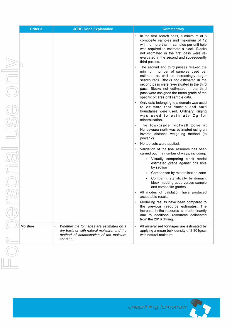
• In the first search pass, a minimum of 8
composite samples and maximum of 12
with no more than 4 samples per drill hole
was required to estimate a block. Blocks
not estimated in the first pass were re-
evaluated in the second and subsequently
third passes.
• The second and third passes relaxed the
minimum number of samples used per
estimate as well as increasingly larger
search radii. Blocks not estimated in the
second pass were re-evaluated in the third
pass. Blocks not estimated in the third
pass were assigned the mean grade of the
specific pit area drill sample data.
• Only data belonging to a domain was used
to estimate that domain and hard
boundaries were used. Ordinary Kriging
w a s u s e d t o e s t i m a t e C g f o r
mineralisation.
• T h e l o w - g r a d e f o o t w a l l z o n e a t
Nunasvaara north was estimated using an
inverse distance weighting method (to
power 2).
• No top cuts were applied.
• Validation of the final resource has been
carried out in a number of ways, including:
• Visually comparing block model
estimated grade against drill hole
by section
• Comparison by mineralisation zone
• Comparing statistically, by domain,
block model grades versus sample
and composite grades
• All modes of validation have produced
acceptable results.
• Modelling results have been compared to
the previous resource estimates. The
increase in the resource is predominantly
due to additional resources delineated
from the 2016 drilling.
Moisture • Whether the tonnages are estimated on a
dry basis or with natural moisture, and the
method of determination of the moisture
content.
• All mineralised tonnages are estimated by
applying a mean bulk density of 2.801g/cc,
with natural moisture.
Fo
r pers
onal use
on
ly
http://www.talgaresources.com/irm/PDF/1455/KiskamaIOCGProjectDrillingResultsPage 21
Criteria JORC Code Explanation Commentary
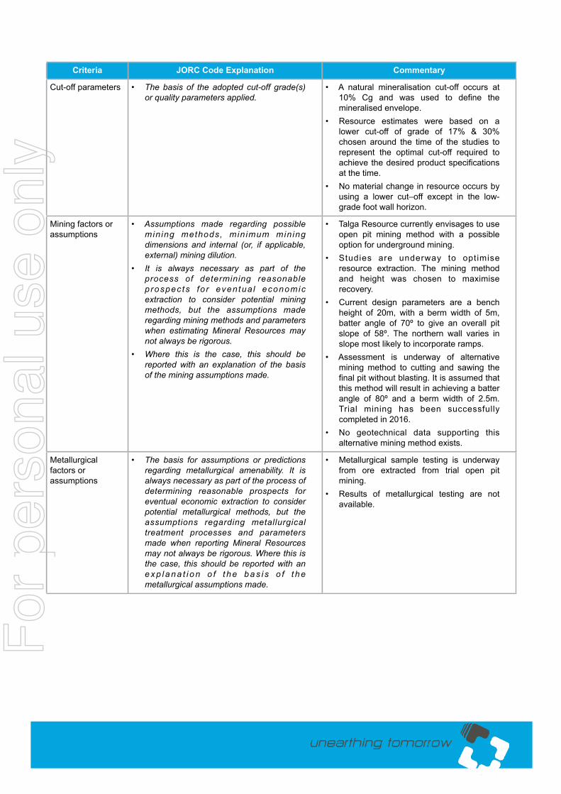
Cut-off parameters • The basis of the adopted cut-off grade(s)
or quality parameters applied.
• A natural mineralisation cut-off occurs at
10% Cg and was used to define the
mineralised envelope.
• Resource estimates were based on a
lower cut-off of grade of 17% & 30%
chosen around the time of the studies to
represent the optimal cut-off required to
achieve the desired product specifications
at the time.
• No material change in resource occurs by
using a lower cut–off except in the low-
grade foot wall horizon.
Mining factors or
assumptions
• Assumptions made regarding possible
mining methods, minimum mining
dimensions and internal (or, if applicable,
external) mining dilution.
• It is always necessary as part of the
process of determining reasonable
prospects fo r eventua l economic
extraction to consider potential mining
methods, but the assumptions made
regarding mining methods and parameters
when estimating Mineral Resources may
not always be rigorous.
• Where this is the case, this should be
reported with an explanation of the basis
of the mining assumptions made.
• Talga Resource currently envisages to use
open pit mining method with a possible
option for underground mining.
• Studies are underway to optimise
resource extraction. The mining method
and height was chosen to maximise
recovery.
• Current design parameters are a bench
height of 20m, with a berm width of 5m,
batter angle of 70º to give an overall pit
slope of 58º. The northern wall varies in
slope most likely to incorporate ramps.
• Assessment is underway of alternative
mining method to cutting and sawing the
final pit without blasting. It is assumed that
this method will result in achieving a batter
angle of 80º and a berm width of 2.5m.
Trial mining has been successfully
completed in 2016.
• No geotechnical data supporting this
alternative mining method exists.
Metallurgical
factors or
assumptions
• The basis for assumptions or predictions
regarding metallurgical amenability. It is
always necessary as part of the process of
determining reasonable prospects for
eventual economic extraction to consider
potential metallurgical methods, but the
assumptions regarding metallurgical
treatment processes and parameters
made when reporting Mineral Resources
may not always be rigorous. Where this is
the case, this should be reported with an
e x p l a n a t i o n o f t h e b a s i s o f t h e
metallurgical assumptions made.
• Metallurgical sample testing is underway
from ore extracted from trial open pit
mining.
• Results of metallurgical testing are not
available.
Fo
r pers
onal use
on
ly

http://www.talgaresources.com/irm/PDF/1455/KiskamaIOCGProjectDrillingResultsPage 22
Criteria JORC Code Explanation Commentary
Environmental
factors or
assumptions
• Assumptions made regarding possible
waste and process residue disposal
options. It is always necessary as part of
the process of determining reasonable
prospects fo r eventua l economic
extraction to consider the potential
environmental impacts of the mining and
processing operation. While at this stage
t h e d e t e r m i n a t i o n o f p o t e n t i a l
environmental impacts, particularly for a
greenfields project, may not always be
well advanced, the status of early
cons ide ra t i on o f t hese po ten t i a l
environmental impacts should be reported.
Where these aspects have not been
considered this should be reported with an
exp lanat ion o f the env i ronmenta l
assumptions made.
• Based on mining studies, volumes of ore
and waste have been quantified. Further
studies are required for waste disposal.
Bulk density • Whether assumed or determined. If
assumed, the basis for the assumptions. If
determined, the method used, whether
wet or dry, the f requency of the
measurements, the nature, size and
representativeness of the samples.
• The bulk density for bulk material must
have been measured by methods that
adequately account for void spaces (vugs,
porosity, etc.), moisture and differences
between rock and alteration zones within
the deposit.
• Discuss assumptions for bulk density
estimates used in the evaluation process
of the different materials.
• Bulk densities used in the Mineral
Resource Estimate are based on a mean
bulk densi ty o f 2 .801g/cc for a l l
mineralisation.
• The bulk density determination was as
follows: both the mean and geomean of
147 field measurements using the
Archimedes principal. Laboratory
measurements by ALS Malå report within
th is to lerance. The same densi ty
measurements where applied as prior
resource reporting.
Classification • The basis for the classification of the
Mineral Resources into varying confidence
categories.
• Whether appropriate account has been
taken of all relevant factors (i.e. relative
confidence in tonnage/grade estimations,
reliability of input data, confidence in
continuity of geology and metal values,
quality, quantity and distribution of the
data).
• Whether the result appropriately reflects
the Competent Person’s view of the
deposit.
• The Mineral Resource has been classified
in the Indicated and Inferred categories, in
accordance with the 2012 Australasian
Code for Reporting of Mineral Resources
and Ore Reserves (JORC Code).
• A range of criteria has been considered in
determining this classification including:
• Geological continuity
• Data quality
• Drill hole spacing
• Modelling techniques
• Estimation properties including
search s t ra tegy, number o f
informing data, average distance of
data from blocks and estimation
output from the interpolation
• Ind icated resources are typ ica l ly
supported by a drill hole spacing not
exceeding 50m.Fo
r pers
onal use
on
ly

http://www.talgaresources.com/irm/PDF/1455/KiskamaIOCGProjectDrillingResultsPage 23
Criteria JORC Code Explanation Commentary
• Inferred resources are largely based on
confidence in geological continuity, wider
drill spacing or isolated mineralisation with
limited drill and sample data.
• The results of the validation of the block
model shows acceptable correlation of the
input data to the estimated grades.
• The Mineral Resource Classification
reflects the views of the Competent
Person.
Audits or reviews • The results of any audits or reviews of
Mineral Resource estimates.
• Various aspects of the data acquisition,
assaying, geological modelling and
r e s o u r c e e s t i m a t i o n h a v e b e e n
independently reviewed at various times
over the life of the project, including this
estimate, by a second CP. This included
audit of standard insertion, core storage,
sampling intervals recorded vs reported
and review of QA/QC protocol.
Discussion of
relative
accuracy/
confidence
• Where appropriate a statement of the
relative accuracy and confidence level in
the Mineral Resource estimate using an
approach or procedure deemed
appropriate by the Competent Person. For
example, the application of statistical or
geostatistical procedures to quantify the
relative accuracy of the resource within
stated confidence limits, or, if such an
approach is not deemed appropriate, a
qualitative discussion of the factors that
could affect the relative accuracy and
confidence of the estimate.
• The statement should specify whether it
relates to global or local estimates, and, if
local, state the relevant tonnages, which
should be relevant to technical and
economic evaluation. Documentation
should include assumptions made and the
procedures used.
• These statements of relative accuracy and
confidence of the estimate should be
compared with production data, where
available.
• Calculated accuracy and confidence in the
Mineral Resource Estimate are not
explicitly stated.
• However, relative accuracy is reflected in
the resource classification, based on
relative kriging variance output from the
estimation algorithms.
• The Indicated Mineral Resource Estimates
are considered to represent a local
es t ima te as the re i s reasonab le
confidence in the location of mineralisation
and waste domains.
• Inferred Mineral Resource Estimates are
less certain, particularly on strike and at
depth due to limited drill hole data density.
Fo
r pers
onal use
on
ly