resolver installation considerations - signature … guides/resolver installation... · 04/07/00...
TRANSCRIPT

Printed in U.S.A.
Resolver InstallationResolver InstallationResolver InstallationResolver InstallationConsiderationsConsiderationsConsiderationsConsiderations
ForForForFor
The SignatureACE™ and SmartSAM™ Systems
3rd revision 7/29/97
13375 N. Stemmons Freeway, Suite 320Dallas, TX 75234-5774 USA
PH: 972-488-9777FX: 972-488-2924
www.signaturetechnologies.com

04/07/00 Resolver Installation Page #1

Page #2 Resolver Installation 04/07/00
Table of Contents
GENERAL Information:.................................................................................................................................3
MOUNTING REQUIREMENTS:...................................................................................................................3
Resolver Physical Specifications: ..................................................................................................................5
Resolver Mechanical / Environmental Specifications: ..................................................................................6
Do's and Donts: .............................................................................................................................................6
DESIGN PRACTICES: ..................................................................................................................................7Mounting the resolver:..........................................................................................................................7Resolver cable control: .........................................................................................................................8Driving the resolver from the END of the crankshaft: .........................................................................8
Design considerations for end-driving the resolver: .....................................................................................9
Auxiliary Drive resolver mounting: ...............................................................................................................12
Driving the Resolver with a Timing Belt: ......................................................................................................13Design considerations for Timing Belt driving the resolver: ...............................................................14
Required information for Resolver mount design:.........................................................................................16
FOR LINEAR APPLICATIONS:....................................................................................................................18
Installation assistance: ..................................................................................................................................21
List of illustrations:
Figure # 1 - S.T.I. Standard Resolver Package ...........................................................................................5Figure # 2 - Side view - Resolver end drive.................................................................................................9Figure # 3 - Top view - Resolver end drive ...............................................................................................10Figure # 4 - Cushion mounts for Resolver bracketry ................................................................................11Figure # 5 - Drive flange arrangement......................................................................................................12Figure # 6 - Auxiliary drive resolver mounting .........................................................................................13Figure # 7 - General arrangement for a Timing Belt resolver drive.........................................................14Figure # 8...................................................................................................................................................15Figure # 9 - Resolver mounting area dimension sketch ............................................................................17Figure # 10 - Linear encoder arrangement ...............................................................................................19Figure # 11 - Typical Inductosyn™ installation........................................................................................20
04/07/00 Resolver Installation Page #3
GENERAL Information:
This write-up is intended to provide information on what is required in order to properly mountand drive a Signature Technologies Resolver.
While it is impossible to enumerate all the possibilities, several illustrations are provided ofcommon types of mountings.
Signature Technologies always stands ready to provide installation support all the way from ahelpful phone call, to a turnkey installation, and anywhere in between. Normally in order todesign a resolver drive, very specific information is needed about the machine.
A concept can be arrived at with nothing more than photographs of the machine, but a completedesign depends of having quantitative information. For example, the end of the crankshaft on astraight side press probably has a tapped hole that could be used for the installation of a drivestub. Before the stub could be designed though, the size of the hole and its thread configurationwould have to be known before the stub could be designed.
The information needed is easy to come by if the machine is sitting in your facility, but must betransmitted to a designer who works off site.
Normally, if Signature Technologies Inc. is to be involved in installation design, at least one tripto the customer's site previous to the start of application design, or delivery of materials will berequired. The trip will be made in order to take the measurements that will be required, andvisually inspect the proposed application for feasibility.
Alternatively, if the installation is really simple, we can try to work from information supplied tous by the customer (sample worksheet is included at the back of this publication).
When working from customer supplied specifications; however, Signature Technologies Inc. willnot accept the responsibility for, or any penalty resulting from, installation problems resultingfrom the existence of obstructions, clearance situations, or dimensional incompatibilitiesresulting from inaccurate, or missing data from the customer.
MOUNTING REQUIREMENTS:
The function of the resolver in the Signature Technologies Inc. signatureACE™ / SmartSAM™system is the provision of positional information, generally of a rotary type, to the SAM500Statistical Analysis module. The data from the machine process is gathered based on thepositional signals that the resolver produces. If the resolver data is an accurate representation ofactual machine motion, the signature data produced thereby will accurately reflect the processstatus. If there are differences in the position data caused by rotary vibration, lost motion, ordrive inaccuracies, the Signature data will be flawed and sensitivity to process changes will belost.

Page #4 Resolver Installation 04/07/00
The primary thing we are always after is a torsionally rigid connection between the pressCRANKSHAFT, and the Resolver. Preferably, the resolver will be driven directly by thecrankshaft through a flexible coupling to absorb radial and axial movement of the crankshaft.
While the resolvers who are used with programmable limit switches, and stroke positionauxiliaries are often hooked in behind the Cam Limit Switch, our resolver must not be mountedthis way. A programmable switch normally runs at 1-2 degree accuracy, and generally not morethan 0.36 degrees of basic resolution. This type of accuracy is fine for programmable switches,but is well outside the requirement for Signature Analysis activities. The SAM500 moduleoperates normally at 0.088 degrees resolution, and any inaccuracy in the resolver drive willimmediately show up as horizontal migration in the signature. The process limits must bewidened to accommodate any horizontal migration, thus reducing the sensitivity of the SignatureAnalysis system to actual process variations, which may be smaller than the mechanicaluncertainty of the resolver drive system.
NOTE:
The resolver unit is an industrial package, with excellent specifications as are listed on the nextpages. It is, however, a precision instrument, and must be treated as such if proper service is tobe obtained.
NEVER strike the resolver shaft in any way from any direction. This includes DRIVING ONpulleys or couplings that are more than a push fit on the shaft. The 95-pound limit on the shaftend is really easy to exceed when driving a coupling on with a hammer. In general if it's too tightto slip on by hand IT'S TOO TIGHT! Open the bore before installing it.
NEVER install belting by "Stretching" it over the pulley edge without loosening the adjustment.This can overload the bearings and cause premature failure.
NEVER Over-tighten the drive belt. Tighten only until there is no perceptible slack. Beltdeflection under light finger pressure should be in the 3/8" to 1/2" range.
NEVER modify the resolver shaft. Machining, drilling, or other modification of the resolvershaft VOIDS THE WARRANTY.
We don’t recommend couplings or pulleys that affix using a setscrew, unless thepulley/coupling has a properly fitted key, and the setscrew bears down on the key surface. It'sgenerally better and more reliable to use CLAMP Hubs.

04/07/00 Resolver Installation Page #5
Resolver Physical Specifications:
Figure # 1 - S.T.I. Standard Resolver Package
Page #6 Resolver Installation 04/07/00
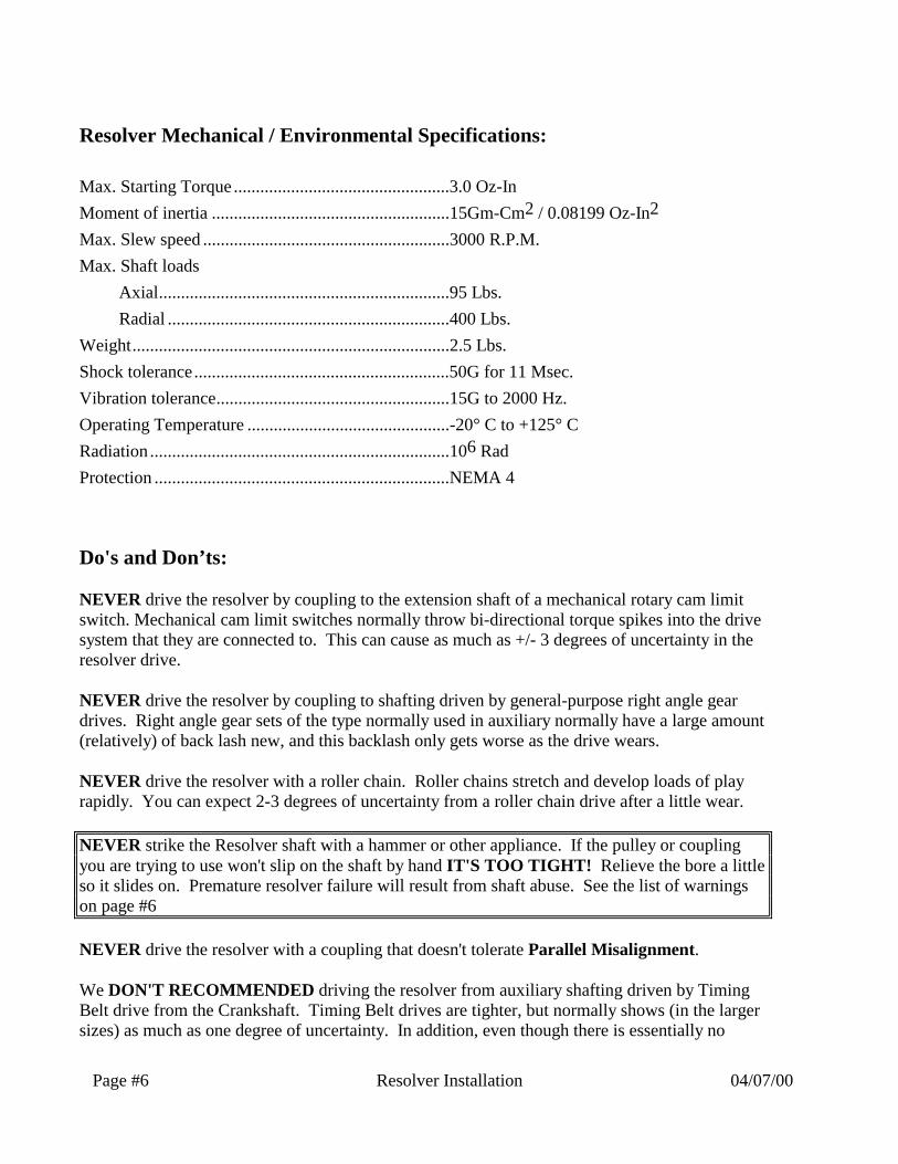
Resolver Mechanical / Environmental Specifications:
Max. Starting Torque .................................................3.0 Oz-In
Moment of inertia ......................................................15Gm-Cm2 / 0.08199 Oz-In2
Max. Slew speed ........................................................3000 R.P.M.
Max. Shaft loads
Axial..................................................................95 Lbs.
Radial ................................................................400 Lbs.
Weight........................................................................2.5 Lbs.
Shock tolerance..........................................................50G for 11 Msec.
Vibration tolerance.....................................................15G to 2000 Hz.
Operating Temperature ..............................................-20° C to +125° C
Radiation ....................................................................106 Rad
Protection ...................................................................NEMA 4
Do's and Don’ts:
NEVER drive the resolver by coupling to the extension shaft of a mechanical rotary cam limitswitch. Mechanical cam limit switches normally throw bi-directional torque spikes into the drivesystem that they are connected to. This can cause as much as +/- 3 degrees of uncertainty in theresolver drive.
NEVER drive the resolver by coupling to shafting driven by general-purpose right angle geardrives. Right angle gear sets of the type normally used in auxiliary normally have a large amount(relatively) of back lash new, and this backlash only gets worse as the drive wears.
NEVER drive the resolver with a roller chain. Roller chains stretch and develop loads of playrapidly. You can expect 2-3 degrees of uncertainty from a roller chain drive after a little wear.
NEVER strike the Resolver shaft with a hammer or other appliance. If the pulley or couplingyou are trying to use won't slip on the shaft by hand IT'S TOO TIGHT! Relieve the bore a littleso it slides on. Premature resolver failure will result from shaft abuse. See the list of warningson page #6
NEVER drive the resolver with a coupling that doesn't tolerate Parallel Misalignment.
We DON'T RECOMMENDED driving the resolver from auxiliary shafting driven by TimingBelt drive from the Crankshaft. Timing Belt drives are tighter, but normally shows (in the largersizes) as much as one degree of uncertainty. In addition, even though there is essentially no

04/07/00 Resolver Installation Page #7
"backlash" in a Timing Belt drive, there is some stretch, which translated to positionaluncertainty if a variable torque load (like an indexer or a roller cam feed) is being driven. On theother hand, torque induced positional uncertainty in a Timing Belt drive tends to be repeatablefrom revolution to revolution and may not constitute a serious problem. The user should beaware, however, that his position reference might be distorted by several degrees at certain pointsof the rotation.
We DON'T RECOMMEND driving the resolver with any Timing Belt drive where thesprockets are smaller than 4" in diameter. This is because as the sprocket diameter gets smaller,the positional uncertainty at the resolver resulting from tooth clearance gets larger. Normally,only one of the sprockets will require flanges for belt guidance.
We APPROVE OF resolver drives that couple directly to the crankshaft through a flexiblecoupling. The simplest coupling where there is NO end float in the crankshaft is a 3" piece ofhydraulic hose applied with worm drive hose clamps. Better are the machined aluminum"Helical" type couplings (like MICRON, or HELICAL). In cases of extreme end float the disktype coupling (like RENBRANDT) is a good bet.
We APPROVE OF resolver drives that use type "XL" (0.200 pitch) or 3.5"or greater diametertype "L" (0.375 pitch) Timing Belt drive systems from the crankshaft. These are slightly lessaccurate than direct coupling, but still very acceptable. In this case watch for radial play in thecrankshaft to avoid over stretching and possible damage to the drive belt and resolver bearings.
We APPROVE OF resolver drives from the auxiliary drive shafts on larger machines, as long asthe ST Resolver drive is either directly coupled to the auxiliary drive gear shaft, or Timing Beltdriven from it before any additional coupling or gearing is done. The auxiliary drive system onlarger presses is generally not "ultra tight" but due to the large diameter of the gears, and a lot offlywheel effect, they still have a relatively good accuracy. We want; however, to be driven rightfrom the auxiliary source, without any interposed gearing or couplings that can generate play. Onlarger machines, this is often the only alternative for resolver drive since the shafts that carry thedrive cams don't turn.
DESIGN PRACTICES:
In general, you should go for rigidity, and very low torsional compliance in the resolver drive.
The primary thing that you want to accomplish is that the resolver shaft should always move intotal synchronism with the crankshaft (or other final drive element) of your machine.
Mounting the resolver:
It is not necessary to shock mount the resolver in any but the most brutal applications.

Page #8 Resolver Installation 04/07/00
The Resolver has mounting provisions on its SIDE surface for four 1/4-20 mounting bolts, wesuggest this as the preferable method. The screws should be installed with medium strengthLoctite™ to prevent loosening.
It is generally a good idea NOT to use END mounting for the unit even though provision hasbeen made for it. END mounting tends to produce a large cantilevered load on the mountingscrews which will be likely to cause them to loosen in the long run, It will also cause amplifiedvibration at the connector end of the resolver unit that is not good for either connector or cablelife.
Resolver cable control:
The mounting bracket should be designed with provision for tying down the resolver cablewithin 6-8 inches of the connector so excessive lengths are not allowed to wave in the breeze.Simply attaching the cable to the bracket with drilled holes, and tie-wraps can prevent a lot ofcable maintenance in the long run.
Driving the resolver from the END of the crankshaft:
If the end of the crankshaft is unencumbered with feed drive or auxiliary apparatus, and there is asolid surface to mount the resolver bracket to, we prefer to end drive the resolver as illustratedbelow.
04/07/00 Resolver Installation Page #9
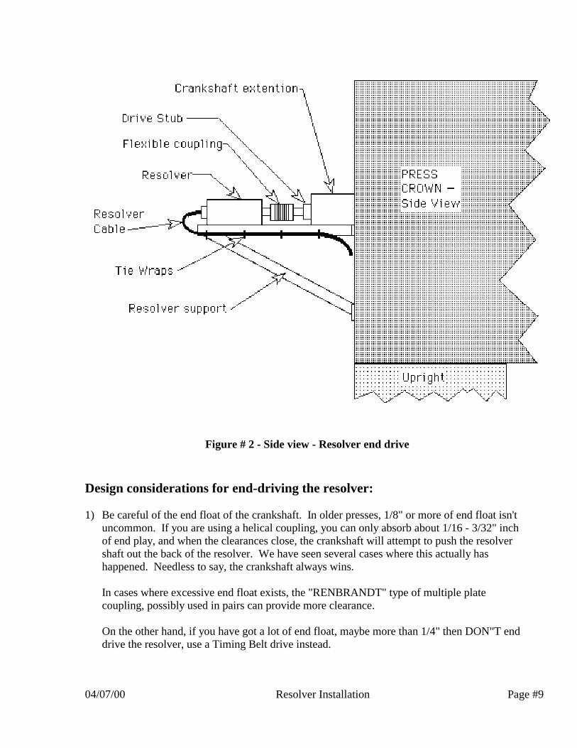
Figure # 2 - Side view - Resolver end drive
Design considerations for end-driving the resolver:
1) Be careful of the end float of the crankshaft. In older presses, 1/8" or more of end float isn'tuncommon. If you are using a helical coupling, you can only absorb about 1/16 - 3/32" inchof end play, and when the clearances close, the crankshaft will attempt to push the resolvershaft out the back of the resolver. We have seen several cases where this actually hashappened. Needless to say, the crankshaft always wins.
In cases where excessive end float exists, the "RENBRANDT" type of multiple platecoupling, possibly used in pairs can provide more clearance.
On the other hand, if you have got a lot of end float, maybe more than 1/4" then DON"T enddrive the resolver, use a Timing Belt drive instead.

Page #10 Resolver Installation 04/07/00
2) Be careful of "oil-canning" in the mount surface. We don't recommend attaching the resolvermount tripod to a sheet metal end cover, as would be installed over a drive gear. Excessivehorizontal motion of the mounting surface will cause bearing problems and broken couplings.Use a Timing Belt drive instead.
Figure # 3 - Top view - Resolver end drive
3) Make sure you tie the cable down to the support members as close to the connector on theresolver as possible to eliminate swing. Any motion between the cable and the connectorwill result eventually in a broken cable. The strain relief on the connector is help, but won'tdo the job alone. The cable must be tie-wrapped to the support structure.
4) Watch out for excessive vibration at the resolver mounting position. If the press really"hammers" it is possible to cushion the shock be installing Pads of "FABREEKA" or similarmaterial between the tripod legs and the press. The idea is not to overly cushion the resolver
bracket, but merely to eliminate high frequency shock. The type of shock energy that willhurt the resolver normally has a high frequency, but very little amplitude (actual motion). So
a relatively stiff isolation technique can eliminate the damaging vibrations without

04/07/00 Resolver Installation Page #11
compromising the angular accuracy of the resolver.
Figure # 4 - Cushion mounts for Resolver bracketry
5) Make sure your mount design allow some means to correct for Parallel Misalignmentbetween the resolver and the crankshaft. If the shafts don't line up, broken couplings will bethe inevitable result. Something as simple as shims under the resolver, or slotted holesallowing the pieces of the mount to be adjusted slightly will do the job.
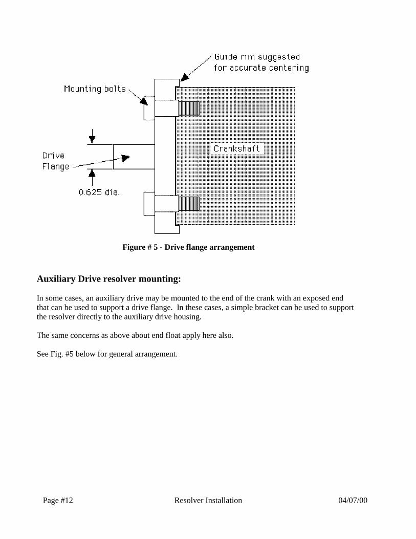
6) The "drive stub" is preferably a machined part that adapts the threaded hole generally foundin the end of the crankshaft to a shaft 0.6250" in diameter onto which the drive coupling ofthe resolver can slip. In case there is not a threaded hole available, a drive flange can be usedas shown in the illustration on the next page.
Note that the drive flange has a Guide rim that accurately centers the flange on the crankshaft.This configuration should be used wherever possible.
Page #12 Resolver Installation 04/07/00
Figure # 5 - Drive flange arrangement
Auxiliary Drive resolver mounting:
In some cases, an auxiliary drive may be mounted to the end of the crank with an exposed endthat can be used to support a drive flange. In these cases, a simple bracket can be used to supportthe resolver directly to the auxiliary drive housing.
The same concerns as above about end float apply here also.
See Fig. #5 below for general arrangement.

04/07/00 Resolver Installation Page #13
Figure # 6 - Auxiliary drive resolver mounting
Driving the Resolver with a Timing Belt:
In cases where the end of the crankshaft is not free, or there is no easily accessible rigid mountingsurface for the resolver bracket, then the alternative is to use Timing Belt drive as illustratedbelow:

Page #14 Resolver Installation 04/07/00
Figure # 7 - General arrangement for a Timing Belt resolver drive
Design considerations for Timing Belt driving the resolver:
1) Use ONLY fine pitch Timing Belts. The Type “L" (0.375 pitch) belts are preferred for mostindustrial applications. If space is a consideration, then Type "XL" (0.200 pitch) belts arefine.
Larger pitch belts get progressively more "sloppy" in terms of their angular accuracy.
2) Use LARGE diameter pulleys. The large pulley diameter minimizes inaccuracies due totooth clearance. We recommend at least 4” P.D. in the “L” (0.375 pitch) type belt.
3) Use double flanges only on the DRIVE pulley.

04/07/00 Resolver Installation Page #15
We don't use flanges on the resolver pulley to avoid the weight. Since there is a lot of shockand vibration in any press installation, Weight on the resolver shaft translates to bearing load,even without the belt tension. See Fig. #8 below.
Figure # 8 - Gear belt drive detail
4) We have found the TRANTORQUE™ device from FENNER-MANNHEIM to be a goodway to affix the drive pulley onto the crankshaft drive stub. Since there is a lot of shock atthe end of the crankshaft, setscrews don't hold terribly well, even if the shaft is flatted. TheTrantorque™ device is a double expanding device that seems impervious to vibration. SeeFig. #8 above.

Page #16 Resolver Installation 04/07/00
5) If the end of the crankshaft is not clear, you can use split pulleys, although they will have tobe specially made to order.
6) If the drive is taken from the crankshaft end, make sure that the drive-stub runs concentricallywith the crankshaft. If there is any problem with lack of concentricity due to inaccuracies inthe crankshaft end threading, or hole location, use a drive flange as in Fig. #5 above.
7) Make sure you include adjustment capability for the resolver so that you can tighten the drivebelt when need be.
The drive belt should be as tight as allowed for the belt size you are using. See themanufacturer's data for guidance. The Resolver shaft is rated 400 pounds radial load, so youdon't have to worry about over-stressing the bearings there.
NOTE: Watch out for radial motion of the crankshaft in older presses that would causeexcessive tightness or looseness in the belt at certain rotational positions as the crankshaftmoves around in its bearings. Yes, I know that you'd never let your press get that loose, butcheck it anyway.
Required information for Resolver mount design:
If you are planning to submit information to Signature Technologies Inc. so that we can assistyou in the design of your resolver mounting, make sure to include the following:
1) The brand, model designation, and SERIAL NUMBER of the machine.
2) Quantitative measurements of the features in the area where you believe the resolver shouldbe mounted. It's not enough to say, "there's a junction box about a foot from the crankshaft,and slightly above it".
3) An actual measurement (to within 1/32") of the end float, and radial motion of the crankshaft.
4) An actual measurement of any oil canning, or flexing motion of the surface on which youwant t mount the Resolver bracketry.
5) If you are going to use a drive stub from the end of the crankshaft, give details of the shaftend including location and dimensions of holes, keyways, and other features. If the shaft iscenter drilled and tapped, give size and thread specifications of the center hole.
6) If possible, a photograph of the mounting area would be helpful.
7) Include at least a sketch along the lines of Fig. #9 below

04/07/00 Resolver Installation Page #17
Figure # 9 - Resolver mounting area dimension sketch

Page #18 Resolver Installation 04/07/00
FOR LINEAR APPLICATIONS:
Sometimes the use of rotary resolvers is clearly impossible since nothing directly related tomachine motion turns. Hydraulic machines are a prime example of this. The only means ofcommutating data must come from the hydraulic ram itself.
What type of position sensor to use:
You must carefully appraise the shock and vibration of the application. If your machine issmooth running as in a Sheet Molding Compound application, then a glass scale linear encoder isa good choice.
If, on the other hand, you are blasting 4" holes through .250 inch stainless steel, your onlypractical choice due to the extreme shock will be an Inductosyn linear resolver.
Some linear encoders have a problem in that they are not "real-time". The output doesn't comedirectly from the code bar like it does with a glass-scale optical encoder. It is generated insteadby internal electronics, and updates at a rate controlled by the electronics, not the motion of theram. Make sure the data conversion/update rate of the device you're considering is at least 10kHz.
The Magnetostrictive type of linear encoder like the "Temposonic" by MTS, or the Balluff deviceare not useable on any but the slowest, smoothest applications since they don't update theirposition data rapidly enough (about 1 kHz or less) to give us the sampling rates we need.
How to couple the position sensor to the slide:
For accuracy, the linear position sensor should be driven as close to the center of the ram aspossible.
This consideration is especially important with column-guided hydraulic presses sinceparallelism control with this design is always pretty poor. The ram will "dance" a lot from cornerto corner with variable die loading. If the encoder is attached to the slide out at the column guidearea, the wobbling will force sampling to be done erratically, giving uncertain positional data.The other problem is that the "wobble" in column guided slides can be pretty high in frequency,causing high accelerations at the encoder which can destroy it.
On the other hand, the center of the slide moves in a more constant fashion. Ideally, the encodercould possibly be driven by a connection very close to the cylinder drive point on the slide orpossibly from double shaft extension on the cylinder itself.
We have gotten acceptable results, however, on gibbed hydraulic machines by coupling theposition sensor drive to the outside of the slide structure. If the gib length is long compared tothe width of the slide (like the Minster/Tranemo presses) the wobbling tendency is eliminated.
04/07/00 Resolver Installation Page #19
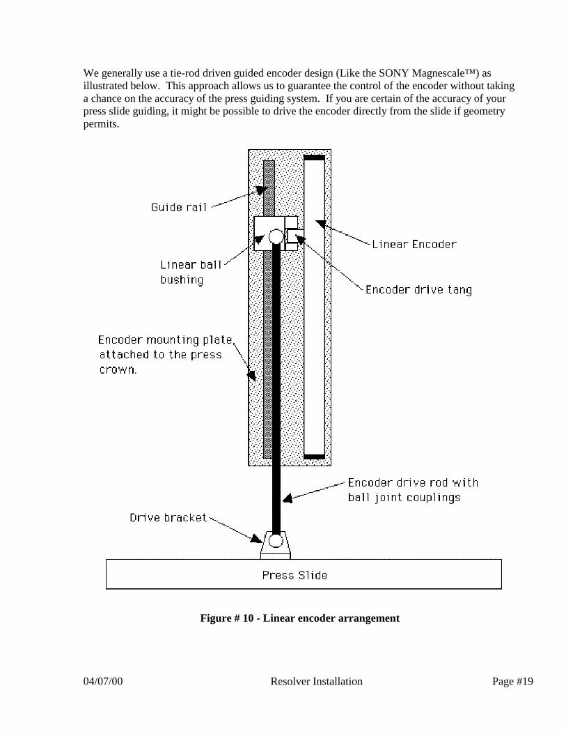
We generally use a tie-rod driven guided encoder design (Like the SONY Magnescale™) asillustrated below. This approach allows us to guarantee the control of the encoder without takinga chance on the accuracy of the press guiding system. If you are certain of the accuracy of yourpress slide guiding, it might be possible to drive the encoder directly from the slide if geometrypermits.
Figure # 10 - Linear encoder arrangement

Page #20 Resolver Installation 04/07/00
For really rugged linear encoding the Inductosyn™ device by Farrand can't be beat. We arrangethe Inductosyn components on a sub-plate with precision guiding, and connect it to the machinevia the same tie rod as the optical encoders. Optionally on large gibbed machines, the Inductosyncomponents could be integrated into the upright structure, using the press gibbing for guidance.
Figure # 11 - Typical Inductosyn™ installation

04/07/00 Resolver Installation Page #21
Signature Technologies Inc. can give guidance on linear applications, which generally require ahigh degree of integration into the existing press structure. In general, due to the sensitive natureof these applications, we would prefer to work in a close relationship with the customer. Weprovide a complete engineering package that the customer can opt to manufacture on his own.We then perform the position sensor sub-system assembly and adjustment, as well as supervisingand tuning the press installation.
Installation assistance:
As stated above, Signature Technologies Inc. stands ready to assist you with your installation.
We will assist by phone in any area that you want to discuss, and have a variety of technicalpublications addressing various topics that have come up in the course of installing theSignatureACE™ or SmartSAM™ systems in the field.
If engineering is needed, we can provide it to any level you want. Call us with details of yourrequirement, and we will respond with a quote for services.
Contact us at:
Signature Technologies Inc.13375 N. Stemmons Freeway, Suite 320Dallas, TX 75234-5774Phone: 972-488-9777Fax: 972-488-2924Website: www.signaturetechnologies.comE-mail: [email protected]