resistron · resm-5 page 3 1 safety and warning notes this resistron monitoring device is...
TRANSCRIPT

RESISTRON
Industrie-Elektronik GmbH Tel.: +49 (0)7142-7776-0 E-Mail: [email protected]äcker 21 Fax: +49 (0)7142-7776-211 Internet: www.ropex.deD-74321-Bietigheim-Bissingen Data subject to change
1.9.
15
RESM-5
Important features
• Microprocessor technology
• OLED display (yellow / green), 4 lines, 20 characters (multilingual)
• Automatic zero calibration (AUTOCAL)
• Automatic configuration of the secondary voltage and current ranges (AUTORANGE)
• Diagnostic interface for the PC visualization software
• Automatic frequency adjustment
• Heatsealing band alloy and temperature range selectable
• Configurable alarm output
• Configurable RESET input
• 0…10VDC analog output for ACTUAL temperature, electrically isolated
• 24VDC control inputs for AUTOCAL and ALARM-IN/RESET, electrically isolated
• Alarm function with error diagnosis
Functionally compatible with the RESM-4
Operating Instructions

Page 2 RESM-5
Contents
1 Safety and warning notes . . . . . . . . . . . . . . 3
1.1 Use . . . . . . . . . . . . . . . . . . . . . . . . . . . 3
1.2 Heatsealing band . . . . . . . . . . . . . . . . 3
1.3 Impulse transformer . . . . . . . . . . . . . . 3
1.4 Current transformer PEX-W2/-W3 . . . . 3
1.5 Line filter . . . . . . . . . . . . . . . . . . . . . . . 4
1.6 Standards / CE marking . . . . . . . . . . . 4
1.7 Warranty provisions . . . . . . . . . . . . . . . 4
2 Application . . . . . . . . . . . . . . . . . . . . . . . . . . 4
3 Basics of temperature control / measurement . . . . . . . . . . . . . . . . . . . . . . . . 5
3.1 Problem . . . . . . . . . . . . . . . . . . . . . . . . 5
3.2 Basics . . . . . . . . . . . . . . . . . . . . . . . . . 6
3.3 Fault causes . . . . . . . . . . . . . . . . . . . . 7
3.4 Measures to reduce the risk of overheating . . . . . . . . . . . . . . . . . . . . . 8
3.5 Possible faults and how to detect them 9
3.6 Residual risks . . . . . . . . . . . . . . . . . . 10
4 Accessories and modifications . . . . . . . . 11
4.1 Accessories . . . . . . . . . . . . . . . . . . . . 11
4.2 Modifications (MODs) . . . . . . . . . . . . 11
5 Technical data . . . . . . . . . . . . . . . . . . . . . . 12
6 Dimensions . . . . . . . . . . . . . . . . . . . . . . . . 13
7 Installation . . . . . . . . . . . . . . . . . . . . . . . . . 14
7.1 Installation procedure . . . . . . . . . . . . 14
7.2 Installation steps . . . . . . . . . . . . . . . . 15
7.3 Wiring diagram . . . . . . . . . . . . . . . . . 17
7.4 Power supply . . . . . . . . . . . . . . . . . . . 18
8 Startup and operation . . . . . . . . . . . . . . . . 18
8.1 View of the unit . . . . . . . . . . . . . . . . . 18
8.2 Unit configuration . . . . . . . . . . . . . . . 18
8.3 Heatsealing band . . . . . . . . . . . . . . . 20
8.4 Startup procedure . . . . . . . . . . . . . . . 20
8.5 Basic functional test on the RESM-5 . 22
9 Unit functions . . . . . . . . . . . . . . . . . . . . . . . 22
9.1 LEDs and controls . . . . . . . . . . . . . . . 22
9.2 Display . . . . . . . . . . . . . . . . . . . . . . . . 23
9.3 Navigation in the menus . . . . . . . . . . 24
9.4 Menu structure . . . . . . . . . . . . . . . . . . 26
9.5 Menu steps . . . . . . . . . . . . . . . . . . . . 28
9.6 Monitoring temperature setting(maximum temperature set point) . . . 31
9.7 Temperature indication / actual value output . . . . . . . . . . . . . . . . . . . . . . . . . 31
9.8 Automatic zero calibration(AUTOCAL) . . . . . . . . . . . . . . . . . . . . 32
9.9 "ALARM-IN/RESET" signal . . . . . . . . 33
9.10 AUTOCAL function disabled . . . . . . . 33
9.11 Temperature unitCelsius / Fahrenheit . . . . . . . . . . . . . . 34
9.12 Disable Configurationmenu . . . . . . . . . . . . . . . . . . . . . . . . . 34
9.13 Display brightness . . . . . . . . . . . . . . . 35
9.14 Undervoltage detection . . . . . . . . . . . 35
9.15 Unit information . . . . . . . . . . . . . . . . . 35
9.16 Diagnostic interface / visualization software . . . . . . . . . . . . . . . . . . . . . . . 36
9.17 System monitoring / alarm output . . . 36
9.18 Error messages . . . . . . . . . . . . . . . . . 37
9.19 Fault areas and causes (main RESISTRON controller) . . . . . . . . . . . 41
10 Factory settings . . . . . . . . . . . . . . . . . . . . . 43
10.1 Customer settings . . . . . . . . . . . . . . . 44
11 Maintenance . . . . . . . . . . . . . . . . . . . . . . . . 44
12 How to order . . . . . . . . . . . . . . . . . . . . . . . . 45
13 Index . . . . . . . . . . . . . . . . . . . . . . . . . . . . . . 46
Safety and warning notes
1 Safety and warning notes
This RESISTRON monitoring device is manufacturedaccording to DIN EN 61010-1. In the course of itsmanufacture it passed through quality assurance,whereby it was subjected to extensive inspections andtests.It left the factory in perfect condition.The recommendations and warning notes contained inthese operating instructions must be complied with, inorder to guarantee safe operation.The device can be operated within the limits indicatedin the "Technical Data" without impairing its operationalsafety. Installation and maintenance may only beperformed by technically trained, skilled persons whoare familiar with the associated risks and warrantyprovisions.
1.1 Use
RESISTRON monitoring devices may only be used forheating and temperature control of heatsealing bandswhich are expressly suitable for them, and providingthe regulations, notes and warnings contained in theseinstructions are complied with.
In case of non-compliance or use contrary tothe intended purpose, there is a risk that
safety will be impaired or that the heatsealing band,electrical wiring, transformer etc. will overheat.Ensuring such compliance is the personalresponsibility of the user.
1.2 Heatsealing band
A basic prerequisite for reliable and safe operation ofthe system is the use of suitable heatsealing bands.
The resistance of the heatsealing band whichis used must have a positive minimum
temperature coefficient in order to guaranteetrouble-free operation of the RESISTRONmonitoring device.
The temperature coefficient must be specified asfollows:
e.g. Alloy-20: TCR = 1100 ppm/KNOREX: TCR = 3500 ppm/K
The RESISTRON monitoring device must be set andcoded according to the temperature coefficient of theheatsealing band.
The use of incorrect alloys with a too lowtemperature coefficient and incorrect coding
of the RESISTRON monitoring device lead touncontrolled heating and ultimately to burn-out ofthe heatsealing band!
The heatsealing bands that were originally suppliedmust be identified by detail specification, part numberor some other means that will assure that replacementbands are identical.
1.3 Impulse transformer
A suitable impulse transformer is necessary to ensurethat the control loop functions perfectly. Thistransformer must be designed according to VDE 0570/EN 61558 (isolating transformer with reinforcedinsulation) and have a one section bobbin. When theimpulse transformer is installed, suitable shockprotection must be provided in accordance with thenational installation regulations for electricalequipment. In addition, water, cleaning solutions andconductive fluids must be prevented from seeping intothe transformer.
Incorrect installation of the impulsetransformer impairs electrical safety.
1.4 Current transformer PEX-W2/-W3
The current transformer supplied with the RESISTRONtemperature controller is an integral part of the controlsystem.
Only the original ROPEX PEX-W2 or PEX-W3current transformer may be used. Other
transformers may cause the equipment tomalfunction.
The current transformer may only be operated if it isconnected to the RESISTRON monitoring devicecorrectly (see section 9, "Startup and operation"). Therelevant safety instructions contained in section 8.3,"Power supply", must be obeyed. External monitoringmodules can be used in order to additionally increase
!
!
TCR 10 4–×10 K 1–≥
!
!
!
RESM-5 Page 3

Application
operating safety. They are not included in the scope ofsupply of the standard control system and aredescribed in a separate document.
1.5 Line filter
The use of an original ROPEX line filter is mandatory inorder to comply with the standards and provisionsmentioned in section 1.6 "Standards / CE marking" onpage 4. This device must be installed and connectedaccording to the instructions contained in section 8.3,"Power supply" as well as the separate documentationenclosed with the line filter.
1.6 Standards / CE marking
The controller described here complies with thefollowing standards, provisions and directives:
Compliance with these standards and provisions is onlyguaranteed if original accessories and/or peripheralcomponents approved by ROPEX are used. If not, thenthe equipment is operated on the user's ownresponsibility.The CE marking on the controller confirms that thedevice itself complies with the above-mentionedstandards.It does not imply, however, that the overall system alsofulfils these standards.It is the responsibility of the machine manufacturer andof the user to verify the completely installed, wired andoperationally ready system in the machine with regardto its conformity with the safety provisions and the EMCdirective (see also section 8.3, "Power supply"). Ifperipheral components (e.g. the transformer or the linefilter) from other manufacturers are used, no functionalguarantee can be provided by ROPEX.
1.7 Warranty provisions
The statutory provisions for warranties apply for aperiod of 12 months following the delivery date.All devices are tested and calibrated in the factory.Devices that have been damaged due to faultyconnections, dropping, electrical overloading, naturalwear, incorrect or negligent handling, chemicalinfluences or mechanical overloading as well asdevices that have been modified, relabeled orotherwise altered by the customer, for example in anattempt to repair them or install additional components,are excluded from the warranty.Warranty claims must be examined in the factory andapproved by ROPEX.
2 Application
If the RESISTRON controller circuit is analyzed indetail, it is clear that a whole series of hardware faultscould conceivably result in dangerous conditions, forinstance because they cause the heatsealing band tooverheat but are not detected by the standard alarmfunction. Even if most of these hardware faults are very
unlikely to occur, such failures can never be completelyruled out.A redundant measuring system, the RESM-5, istherefore essential to monitor the complete controller,including the current transformer.The RESISTRON monitoring device RESM-5 isconnected to an existing RESISTRON control system
DIN EN 61010-1:2001(2006/95/EG)
Safety requirements for electrical equipment for measurement, control and laboratory use(low-voltage directive):pollution degree 2,protection class II,measurement category I
(for UR and IR terminals)
DIN EN 60204-1(2006/42/EG)
Electrical equipment of machines (machinery directive)
EN 55011:1998 + A1:1999 +A2:2002
EN 61000-3-2:2006-04EN 61000-3-3:1995-01 +
A1:2001 + A2:2005-11(2004/108/EG)
EMC genery emissions:Group 1, Class A
EN 61000-6-2:2005(2004/108/EG)
EMC generic immunity:Class A (ESDs, RF radiation, bursts, surges)Exception:Line voltage interruption acc. EN 61000-4-11 is not fulfilled (This leads to a designated error message of the controller)
Page 4 RESM-5

Basics of temperature control / measurement
(any RESISTRON controller in the "400" or "5000"series with an alarm output); it measures the resistanceof the heatsealing band and indicates the temperaturein parallel operation using a separate currenttransformer.The RESM-5 is connected to the line voltage in phasewith the main controller. The measuring voltage UR isdrawn from the main controller for practical reasons
while the current transformer signal IR is supplied by aseparate current transformer.A variable limit function is used to monitor the maximumtemperature; an alarm (fault) is indicated at the alarmoutput of the RESM-5 if the limit value is exceeded.
To prevent dangerous situations, refer to therisk analysis for the machine or plant.
3 Basics of temperature control / measurement
The following section starts by outlining the possiblecauses of unwanted overheating when the temperatureof a heatsealing band is controlled according to theresistance principle.
3.1 Problem
When the temperature of a heatsealing band iscontrolled according to the resistance principle, theband acts both as a heat source and as a temperaturesensor. The heatsealing band supplies a unique
!
UR
IR
LOA
D
LIN
E
RESISTRON
UR
IR (RESM)
RESM
MONITORING
MAIN CONTROLLER
Alarmoutput
Alarmoutput
Kb’
Kb
+24VDC
+24VDC
0V
0VControl signalto PLC
Control signalto PLC
Kb’Kb
Kb’Kb
Co
nnec
t lin
e vo
ltage
in p
has
e
RESM-5 Page 5

Basics of temperature control / measurement
resistance value for each temperature based on itsalloy-specific TCR (temperature coefficient ofresistance).This value may be altered by external impacts such aspartial short-circuits, contacting problems, changedcross sections etc., i.e. the controller measures anincorrect resistance and responds by increasing orreducing the heating current, depending on thedirection of the change, in an attempt to "follow" thisfalse set point. Major deviations from the temperatureset point are often attributable to faults such as these.Whereas an increase in the measured resistance(narrower cross section due to physical damage,
detached or corroded clamps, worn copper plating)simply leads to a harmless reduction in the actualheatsealing band temperature, a partial short-circuit(ground fault, conductive foreign particles, physicalcontact between two heatsealing bands) can cause thetemperature of the band sections which are still activeto rise significantly. Dangerous levels involving a risk offire or explosion can then occur very quickly.Depending on the design, execution, and wiring of theheatsealing tools and the interconnection of theheatsealing bands, numerous potential fault causescan thus be identified.
3.2 Basics
The diagram below is an electrical schematic of asealing bar showing the heatsealing band and thepower and measurement cables.
Note:
The term "measured resistance" or "resistancemeasured by the controller" is used in this document torefer to the resistance between two connection pointsA - A' on the voltage measurement cable UR.In the diagram on page 6 this is the resistance R.
Only resistance faults which occur between themeasuring points A - A' are relevant for theoverheating problems described here. External faults
are not visible to the controller and are therefore notimportant for our purposes.
R
r
R
Voltage measurement cable UR
Controller
RES
UR
IR
R
Current transformer
A
D'
CURRENT CONDUCTING PARTSor TRANSITIONS
POWER CONNECTION
EXPANSION JOINT
HEATSEALING BANDCLAMP
COPPERED END
HEATSEALING BAND
B
C'
C
B'
D
A'
ΔR
Δr
Page 6 RESM-5

Basics of temperature control / measurement
If the actual temperature of a heatsealing band in aclosed control loop deviates from the set point, thefollowing relationship is true:
(1)
(2)
In other words, the temperature error depends onthe relative resistance change (due to the fault) and thetemperature coefficient (TCR) of the resistor material.The temperature error can be either positive ornegative depending on the sign of the fault (higher orlower resistance) .The temperature error for the standard heatsealingband alloy where is thus asfollows:
(3)
This relationship is easily explained with the help of anexample:If the heatsealing band is "shortened" 20% electrically
( ) (e.g. by inserting a conducting part), the
temperature error according to (3) is +200K.In this case, the actual heatsealing band temperatureaccording to (2) is as follows:
It is clear from this example that a control system whichoperates according to the resistance principle respondsextremely sensitively to heatsealing band resistancefaults or faults in the associated electromechanicalcomponents.The diagram on page 6 shows how the components A,B, C, and D belonging to the power cable are potentialfault sources, for instance, because any change in thecontact resistances distorts the resistance measuredby the controller.
3.3 Fault causes
If all of the components belonging to the control loopare analyzed with respect to possible faults that couldlead to dangerous overheating, several potentialcauses can be identified, e.g.:
• Contact between two heatsealing bands wired inseries
• Ground fault
• Partial short-circuit
• Non-coppered heatsealing band ends
• Unsuitable heatsealing band alloy ( or toolow)
• Defect in the measuring circuit of the controllerelectronics
• Defect in the power unit of the controller, e.g. triacremains conductive without an ignition signal
• Short circuit in the external wiring such that the triacis bypassed
• Defect in the current transformer
• Short circuit or break in the current or voltagemeasurement cables (UR)
• Operator error
• etc.
Sudden resistance changes which are so large that themeasured resistance is outside of the operating range(below zero or above 300°C / 500°C) can be detectedand indicated by the controller.On the other hand, smaller resistance steps or gradualchanges cannot be detected as faults owing to theoperating principle of the unit, so that the above-mentioned temperature deviations occur.Some of the faults described here can be measured byRESISTRON controllers with an alarm function.Others are detected by the RESISTRON monitoringdevice (RESM-5) and the MSW (refer to the separatedocumentation).Even these two monitoring units are still unable todetect a few fault types ( section 3.6 "Residual risks"on page 10).
ΔTΔRR
--------– 1TCR-------------⋅=
ΔT THL TSet–=
ΔT
ΔR
ΔT
TCR +10 10 4– K 1–⋅=
ΔT 1000 ΔRR
--------– K[ ]⋅=
ΔRR
-------- 0,2–=
THL Set point 200K+=
TCR 0=
RESM-5 Page 7

Basics of temperature control / measurement
3.4 Measures to reduce the risk of overheating
As in any mechanical engineering application, safetyaspects must be taken into account in the heatsealingsystem from the design stage onward. If this rule isobserved, the majority of faults are prevented from theoutset.This document cannot provide detailed designinstructions for sealing tools; only a few particularlyimportant points are mentioned here as a reminder:
Heatsealing band
• Use a heatsealing band with the specified TCR
• Copper the ends at least 10 mm into the bar
• Protect the coppered ends with a layer of nickel orgold if there is a risk of corrosion
Bar end blocks (the heatsealing band's expansion joints)
• Electrically insulated at both ends
• Tightened at both ends
• Sufficient spring force, unrestricted movement
• Heatsealing band tightly clamped
• Power connection tightly clamped
• No current flowing through moving parts (pivot pinsetc.)
• Carefully executed insulation
Bars
• Flat bars, not warped
• Carefully executed insulation of the heatsealingband
Electrical wiring
• Use cables with an adequate cross section( ROPEX Application Report)
• Use short cables where possible
• Use only plug connectors that conform to ROPEXspecifications ("Basics" documentation)
• Use separate connections to attach themeasurement cables to the bar end blocks
• etc.
To prevent dangerous situations, refer to theinformation provided in the ROPEX
Application Report and the risk analysis for themachine or plant.
!
Page 8 RESM-5

Basics of temperature control / measurement
3.5 Possible faults and how to detect them
Possible fault
Detected with
RESISTRON controller("400" or "500" series) with alarm output
Additionalmonitoring current transformerMSW
Additional,redundant RESISTRON monitoring device RESM-5
Heatsealing band break Yes No Yes
IR and UR measurement cables (break or short
circuit)
Yes No Yes
Contact between two heatsealing bands (wired in series)
Possibly 1 Yes No
Heatsealing band partially short-circuited Possibly 1 No No
Ground fault No Yes No
Zero point suppression due to incorrect calibration
Yes No Yes
Controller hardware defect No No Yes
Triac conductive or bypassed Yes No Yes
Current transformer defect No No Yes
Heatsealing band with too low a TCR ( section 3.6 "Residual risks" on page 10)
No No No
1. If the measured resistance of the heatsealing band changes >10%
RESM-5 Page 9

Basics of temperature control / measurement
3.6 Residual risks
Even if the RESISTRON monitoring device RESM-5(and the optional monitoring current transformer MSW)are used, there are still a few operating states that cancause undetected overheating of the heatsealing band.Some of these fault causes have already beendescribed in detail above.They are summarized again below:
• Non-coppered heatsealing band ends
• Heatsealing band with no TCR or a TCR that is toolow
• Conductive, ungrounded part which partially shortcircuits the heatsealing band during the heatingphase
Consequence: The controller measures a lowerresistance and continues heating to a highertemperature.
• Reduction in the resistance measured by thecontroller (between the two connection points on thevoltage measurement cable UR) during the heatingphase (similar effect to that described above but adifferent cause)
Example:The clamp for the heatsealing band connection
makes poor contact (loose contact) → contactresistance.The sealing tool is open, the heatsealing band iscold, and the controller is calibrated using theAUTOCAL function.The tool closes and the controller heats up.The contact with the heatsealing band improvesunder the closing pressure, the resistance isreduced, and the controller heats to a highertemperature.
In other words:The zero point is calibrated when the circuit has highimpedance.The circuit has lower impedance during the heatingphase.Consequence: Overheating
• Physical damage to the heatsealing band(contraction, cracking etc.) leading to a narrowercross sectionThe heatsealing band overheats at this point(HOT SPOT). It can glow red-hot as a result.
• The resistance increase which occurs here is sosmall in relation to the total resistance that it cannotbe detected by the controller in practice.
• Incorrect operationExample: AUTOCAL is run when the heatsealingband is hot
• Design error regarding the installation and wiring ofthe control and monitoring system.Remedy: Check regularly that the monitoringsystem is working correctly by deliberately inducingshort circuits, breaks etc. (checklist).
Partial short-circuit
Page 10 RESM-5

Accessories and modifications
4 Accessories and modifications
A wide range of compatible accessories and peripheraldevices are available for the RESISTRON monitoringdevice RESM-5. They allow it to be optimally adaptedto your specific heatsealing application as well as toyour plant's design and operating philosophy.
4.1 Accessories
• The products described below are only a few of thewide range of accessories available forRESISTRON monitoring devices ("Accessories"leaflet).
4.2 Modifications (MODs)
Owing to its universal design, the RESISTRONmonitoring device RESM-5 is suitable for a very widerange of heatsealing applications.Modifications (MODs) are available for theRESISTRON monitoring device RESM-5 forimplementing special applications.
MOD 01
Booster for low secondary voltages(UR = 0.25…16VAC). This modification is necessary,for example, for very short or low-resistanceheatsealing bands.
Analog temperature meter ATR-xFor front panel mounting or mounting on a top hat rail (DIN TS35 rail).Analog indication of the ACTUAL temperature of the heatsealing band in °C. The meter damping of the unit is optimized for the abrupt temperature changes that occur in impulse mode.
Line filter LF-xx480Essential to ensure CE conformity.Optimized for the RESISTRON monitoring device.
Communication interface CI-USB-1Interface for connecting a RESISTRON monitoring device with a diagnostic interface (DIAG) to the PC (USB port). Associated PC visualization software for displaying setting and configuration data as well as for recording SET and ACTUAL temperatures in real time.
Monitoring current transformer MSWFor detecting frame short-circuits on the heatsealing band.Used as an alternative to the standard PEX-W2 / W3 current transformer.
UR measurement cable UML-1Twisted cable for measuring the UR voltage.Suitable for drag chains, contains neither halogens nor silicone.
RESM-5 Page 11

Technical data
5 Technical data
Type of construction Housing for installation in the electrical cabinetSnaps onto a standard top hat rail (DIN TS35 rail, 35mm) acc. to DIN EN 50022Dimensions: 90 x 75mm; height: 135mm (incl. terminals)
Line voltage 115VAC version: 110VAC -15%…120VAC +10% (equivalent to 94…132VAC)230VAC version: 220VAC -15%…240VAC +10% (equivalent to 187…264VAC)400VAC version: 380VAC -15%…415VAC +10% (equivalent to 323…456VAC)
Depending on the version selected ( section 12 "How to order" on page 45)
Power supply system Balanced TN or TT system, max. 415VACInstallation category III
Operation in potential-free systems (e.g. an IT system) is only permitted after consultation with ROPEX.
Line frequency 50 / 60Hz(47…63Hz, automatic adjustment to frequencies in this range)
Auxiliary voltageTerminals 12+13
24VDC, +20%, -10%, protected against reverse polarityMax. current input: 1.0A
Measuring range Secondary voltage UR: 0.4…120VACSecondary current IR: 30…500A (with PEX-W2/-W3 current transformer) ROPEX Application report
Heatsealing band type and temperature range
The temperature range and temperature coefficient settings can also be specified independently of one another in the Configuration menu:
Temperature range: 200°C, 300°C, 400°C, or 500°CTemperature coefficient: 400…4000ppm/K (variable setting range)
Analog output(actual value)Terminals 17+14
0…10VDC, Imax = 5mA, electrically isolatedEquivalent to 0…300°C or 0…500°CAccuracy: ±1% plus 50mV
Digital logic levelsTerminals 5, 6, 7
LOW (0V): 0…2VDC, electrically isolatedHIGH (24VDC): 12…30VDC (max. current input: 6mA)Protected against reverse polarity
Alarm outputTerminal 18
UON < 3V (saturation voltage), Imax = 200mA, electrically isolated, short-circuit proof, can be inverted in the Configuration menu
Power dissipation Max. 10VA
Ambienttemperature
+5…+45°C
Degree of protection IP20
!
Page 12 RESM-5

Dimensions
6 Dimensions
Installation and startup may only be per-formed by technically trained, skilled per-
sons who are familiar with the associated risks and
warranty provisions.
Installation A minimum safety clearance of 20mm all round (e.g. from other devices and wiring) must be allowed when installing the controller.
The moving clip required for fastening must be facing down for mounting on a horizontal top hat rail.
End holders to mechanically fix the controller must be fitted at both ends for mounting on a vertical top hat rail.
Weight Approx. 0.7kg (incl. connector plug-in parts)
Housing material Plastic, polycarbonate, UL-94-V0
Connecting cablesType / cross-sections
Rigid or flexible; 0.2…2.5mm² (AWG 24…12)Plug-in connectors
Screw terminals: Clamping torque: 0.5…0.6Nm(Screw driver size: SZS 0.6x3.5mm)
If ferrules are used, they must be crimped in accordancewith DIN 46228 and IEC / EN 60947-1.
This is essential for proper electrical contact in the terminals.nicht gewährleistet.
!
75.0 90.0
113.
0 135
.0
!
RESM-5 Page 13
Installation
7 Installation
See also section 1 "Safety and warning notes" onpage 3.
Installation and startup may only beperformed by technically trained, skilled
persons who are familiar with the associated risksand warranty provisions.
7.1 Installation procedure
Proceed as follows to install the RESISTRONmonitoring device RESM-5:
1. Switch off the line voltage and verify that the circuitis de-energized.
2. The supply voltage specified on the nameplate ofthe RESISTRON monitoring device must beidentical to the line voltage that is present in theplant or machine. The line frequency isautomatically detected by the temperature controllerin the range from 47Hz to 63Hz.
3. Install the RESISTRON monitoring device in thefront panel cutout. It is fastened by means of twoclips which snap onto the side of the controllerhousing.
4. Wire the system in accordance with the instructionsin section 7.3 "Wiring diagram" on page 17,section 7.3 "Wiring diagram" on page 17, and theROPEX Application Report. The informationprovided in section 7.2 "Installation steps" onpage 15 must also be heeded.
Check the tightness of all systemconnections, including the terminals for the
impulse transformer windings.
5. Make sure the wiring conforms to all relevantnational and international installation regulations.
To prevent dangerous situations, refer to therisk analysis for the machine or plant.
!
!
!
Page 14 RESM-5

Installation
7.2 Installation steps
7.2.1 RESM-5 and RESISTRON controllers with separate evaluation of alarms (recommended by ROPEX)
The RESISTRON monitoring device RESM-5 is aseparate unit which should also be integrated as suchin the plant or machine concept.The alarm outputs of the main RESISTRON controllerand the RESM-5 energize separate contactors orrelays (Kb, Kb‘). The alarm output signals are
additionally transferred to the PLC / machine controlsystem as control signals. The alarm outputs of theRESM-5 and the main RESISTRON controller can beseparately evaluated and tested in this way. Theadditional control signals to the PLC / machine controlsystem enable both the status and the sequence of thealarms to be evaluated (e.g. an alarm indicated by themain RESISTRON controller results in an RESM-5alarm). This wiring principle is shown in the diagrambelow.
To prevent dangerous situations, refer to therisk analysis for the machine or plant.!
UR
IR
LOA
D
LIN
E
RESISTRON
UR
IR (RESM)
RESM
MONITORING
MAIN CONTROLLER
Alarmoutput
Alarmoutput
Kb’
Kb
+24VDC
+24VDC
0V
0VControl signalto PLC
Control signalto PLC
Kb’Kb
Kb’Kb
Co
nnec
t lin
e vo
ltage
in p
has
e
RESM-5 Page 15

Installation
7.2.2 RESM-5 and RESISTRON controllers with joint evaluation of alarms (loop-through mode)
The RESISTRON monitoring device RESM-5 has acontrol input for evaluating the alarms of the mainRESISTRON controller. If the main RESISTRONcontroller indicates an alarm, the RESM-5 immediatelyenergizes its own alarm output (loop-through mode).The wiring between the RESM-5 and the main
RESISTRON controller is simpler than when the alarmsare separately evaluated ( section 7.2.1 "RESM-5and RESISTRON controllers with separate evaluationof alarms (recommended by ROPEX)" on page 15). Onthe other hand, it is very difficult to reconstruct thealarm sequence. Servicing and troubleshooting arelikewise more complicated.
To prevent dangerous situations, refer to therisk analysis for the machine or plant.!
UR
IR
LOA
D
LIN
E
RESISTRON
UR
IR (RESM)
RESM
MONITORING
MAIN CONTROLLER
Alarmoutput
Alarmoutput
Kb+24VDC
+24VDC
0V
Kb
Kb
Co
nnec
t lin
e vo
ltage
in p
has
e
Alarminput
Page 16 RESM-5

Installation
7.3 Wiring diagram
ALARM-IN/RESET
with 24VDC signal
AUTOCALwith 24VDC signal
ALARMOUTPUT+24VDC
RESM-5
GND
GND
+24VDC
14
12
7
6
5
R
Impulsetransformer
9
8
4
3
2
1
UR Heat-sealingband
16
17
15
13
18
sec.U2
prim.U1
TwistedAuxiliarypower supply
ANALOGOUTPUT
(actual value)+0...10VDC
0V(Internal ground)NO EXTERNALGROUNDINGALLOWED!
Currenttransformer
PEX-W2/-W3
11
10IR
NC
NC
NC
NC
GroundMust be groundedexternally to pre-vent electrostatic
charging!
LINE
Line filter LF-xx480
Note:If error code 118 appears whenyou switch on the RESM-5,these cables should bereversed/interchanged.
( )*
NC
RESM-5 Page 17

Startup and operation
7.4 Power supply
Refer to the information in the “Power supply” sectionof the documentation for your temperature controller.
The RESISTRON monitoring device and thetemperature controller must both be con-
nected to the same phases of the power supply. Ifnot, they may no longer work correctly.
The RESISTRON monitoring device must be operatedwith an LF-xx480 line filter. It can either be equippedwith a separate line filter or share the same filter as thetemperature controller.
8 Startup and operation
8.1 View of the unit
8.2 Unit configuration
The possible unit configurations are explained in thefollowing sections. Proceed as described insection 8.4.1 "Initial startup" on page 20 to start up theunit for the first time.
8.2.1 Configuration of the secondary voltage and current ranges
The secondary voltage and current ranges areautomatically configured by the automatic calibrationfunction (AUTOCAL). The voltage is configured in therange from 0.4VAC to 120VAC and the current in the
range from 30A to 500A. If the voltage and / or currentare outside of the permissible range, a detailed errormessage appears on the RESISTRON monitoringdevice ( section 9.18 "Error messages" on page 37).If the secondary current I2 is less than 30A, the wiremust be laid twice through the PEX-W2 or PEX-W3current transformer ( ROPEX Application Report).
!
Terminals
Wiring diagram
OLED display
Nameplate
with keys
2x
Page 18 RESM-5

Startup and operation
8.2.2 Menu language
The menu language can be changed while theRESISTRON monitoring device is operating. You set itwith step 201 in the Configuration menu. The followingsettings are possible:English, German
The language selected in this menu remainsset if the factory settings are restored
(step 202 in the Configuration menu).
The language selected with step 201 can stillbe changed even if the Configuration menu is
disabled ( section 9.12 "Disable Configurationmenu" on page 34).
8.2.3 Restoring the factory settings
The internal settings of the RESISTRON monitoringdevice can be reset to the factory defaults with step 202in the Configuration menu. Only the language selectedwith step 201 in the Configuration menu remainsunchanged.Refer to section 10 "Factory settings" on page 43 formore information about the factory settings.
If the unit's settings are unknown when it isstarted up for the first time, you must restore
the factory settings in order to preventmalfunctions.
8.2.4 Configuration of the alloy(temperature coefficient)
The temperature coefficient for your particularheatsealing band can be individually set in the rangefrom 400 to 4000ppm/K with step 204 in theConfiguration menu.
To prevent dangerous situations, refer to therisk analysis for the machine or plant.
8.2.5 Configuration of the temperature range
The temperature range for the RESISTRON monitoringdevice can be set with step 205 in the Configurationmenu.
You can choose between 200°C, 300°C (factorysetting), 400°C, and 500°C.
8.2.6 Configuration the maximum temperature (alarm threshold)
You set the maximum temperature with step 206 in theConfiguration menu. If the measured heatsealing bandtemperature exceeds the maximum temperaturespecified here (alarm threshold), the RESISTRONmonitoring device generates error code 109.
To prevent dangerous situations, refer to therisk analysis for the machine or plant.
8.2.7 Configuration of thealarm output
You set the alarm output with step 215 in theConfiguration menu. There are four possible settings:
1. "normal" (factory setting)The alarm output is energized at alarm.
2. "invers"The alarm output is de-energized at alarm.
3. "normal w. RESET"The alarm output is energized at alarm or when theALARM-IN/RESET input is energized.
4. "inverse w. RESET"The alarm output is de-energized at alarm or whenthe ALARM-IN/RESET input is energized.
Other startup configuration options:
5. "30sec. inactive"The alarm output is de-energized for 30 secondsregardless of any alarms.
6. "1min. inactive"The alarm output is de-energized for 1 minuteregardless of any alarms.
7. "5min inactive"The alarm output is de-energized for 5 minutesregardless of any alarms.
To prevent dangerous situations, refer to therisk analysis for the machine or plant.
!
!
!
!
!
!
RESM-5 Page 19

Startup and operation
8.3 Heatsealing band
8.3.1 General
The heatsealing band is a key component in the controlloop because it is both a heating element and a sensor.The geometry of the heatsealing band is too complex tobe discussed at length here. We shall therefore onlyrefer to a few of the most important physical andelectrical properties.The measuring principle applied for this systemrequires a heatsealing band alloy with a suitabletemperature coefficient TCR, i.e. one whose resistanceincreases as the temperature rises.Too low a TCR leads to oscillation or measurementerrors.If a heatsealing band with a higher TCR is used, theRESISTRON monitoring device must be calibrated forthis.The first time the heatsealing band is heated toapproximately 200…250°C, the standard alloyundergoes a once-only resistance change (burn-ineffect). The cold resistance of the heatsealing band isreduced by approximately 2…3%. However, this at firstglance slight resistance change results in a zero pointerror of 20…30°C. The zero point must therefore becorrected after a few heating cycles ( section 8.3.2"Replacing the heatsealing band" on page 20).One very important design feature is the copper orsilver-plating of the heatsealing band ends. Cold endsallow the temperature to be controlled accurately andincrease the life of the Teflon coating and theheatsealing band.
An overheated or burned-out heatsealingband must no longer be used because the
TCR has been irreversibly altered.
8.3.2 Replacing the heatsealing band
All power supply leads must be disconnected from theRESISTRON monitoring device in order to replace theheatsealing band.
The heatsealing band must be replaced inaccordance with the instructions provided by
the manufacturer. To prevent dangerous
situations, refer to the risk analysis for the machineor plant.
Each time the heatsealing band is replaced, the zeropoint must be calibrated with the AUTOCAL functionwhile the band is still cold in order to compensateproduction-related resistance tolerances. The burn-inprocedure described above should be performed for allnew heatsealing bands.
8.4 Startup procedure
Please also refer to section 1 "Safety and warningnotes" on page 3 and section 2 "Application" onpage 4.
Installation and startup may only beperformed by technically trained, skilled
persons who are familiar with the associated risksand warranty provisions.
8.4.1 Initial startup
Prerequisites: The unit must be correctly installed andconnected ( section 7 "Installation" on page 14).All possible settings are described in detail insection 8.2 "Unit configuration" on page 18 andsection 9 "Unit functions" on page 22.The essential configurations of the RESISTRONmonitoring device are described below:
1. Switch off the line voltage and verify that the circuitis de-energized.
2. The supply voltage specified on the nameplate ofthe unit must be identical to the line voltage that ispresent in the plant or machine. The line frequencyis automatically detected by the RESISTRONmonitoring device in the range from 47 to 63Hz.
3. Make sure no START signal on the temperaturecontroller is applied.
4. Switch on the line voltage.
5. A power-up message appears on the display forapproximately 2 seconds when you switch on themonitoring unit to indicate that it is being poweredup correctly.
!
!
!
Page 20 RESM-5

Startup and operation
6. One of the following states then appears:
7. Configure the unit as described in section 8.2 "Unitconfiguration" on page 18. The following settingsmust always be configured:
8. Run the AUTOCAL function while the heatsealingband is cold (step 107 in the Settings menu or"AUTOCAL" signal, terminals 5+14). The progressof the calibration is indicated by a counter on the
display (approx. 10…15 s). A voltage of 0VDCadditionally appears at the actual value output(terminals 17+13). If an ATR-x is connected, itindicates 0…3°C.When the zero point has been calibrated, thedisplay returns to the home position and an actualvalue of 20°C is indicated. A voltage of 0.66VDC(300°C range) or 0.4VDC (500°C range, equivalentto 20°C), appears at the actual value output instead.If an ATR-x is connected, it must be set to "Z"(20°C).If the zero was not calibrated successfully, an errormessage indicates error codes 104…106, 211. Inthis case the RESM-5 configuration is incorrect( section 8.2 "Unit configuration" on page 18 andROPEX Application Report). Repeat the zero pointcalibration after the unit has been configuredcorrectly.
9. The fact that the ACTUAL temperature is indicatedon the display (digital value and progress bar)means the heating and control process can beobserved:The unit is functioning correctly if the temperatureindicated on the display has a harmonious motion,in other words it must not jump abruptly, fluctuate, ordeviate temporarily in the wrong direction. This kindof behavior would indicate that the UR measurementcable has been laid incorrectly.If an error message is displayed, please proceed asdescribed in section 9.18 "Error messages" onpage 37.
10.Burn in the heatsealing band ( section 8.3"Heatsealing band" on page 20) and repeat theAUTOCAL function.
8.4.2 Restart after replacing the heatsealing band
To replace the heatsealing band, proceed as describedin section 8.3 "Heatsealing band" on page 20.
Always use a heatsealing band with thecorrect alloy, dimensions, and copper plating
in order to avoid malfunctions and overheating.
To prevent dangerous situations, refer to therisk analysis for the machine or plant.
Continue with section 8.4.1, steps 8 and 9.
DISPLAY ACTION
Display in home position Go to step 7
Error message with error code104…106, 109,111…113, 211
Go to step 7
Error message with error code118
Reconnect/Interchange UR
measuring wire to terminals 8+9.Then return tostep 3
Error message with error code101…103, 107, 108,201…203, 801, 9xx
Error diagnosis( section 9.18)
SettingStep in
Configuration menu
Language 201
Restore factory settings 202
Temperature range and heatsealing band alloy
204, 205
The RESM is now ready
!
!
RESM-5 Page 21

Unit functions
8.5 Basic functional test on the RESM-5
To prevent dangerous situations, refer to theinformation provided in the ROPEX Applica-
tion Report and the risk analysis for the machine orplant.
1. Connect the temperature controller and theRESM-5 in accordance with the wiring diagram.
2. Start up the temperature controller and the RESM-5(refer to the documentation for the controller and theRESM-5).
3. Select the required SET temperature using the tem-perature controller (refer to the risk analysis for themachine or plant).
4. Specify a maximum temperature which is less thanthe SET temperature of the temperature controllerwith step 206 in the Settings menu on the RESM-5(refer to the risk analysis for the machine or plant).
5. Activate the START signal on the temperature con-troller.
6. If the maximum temperature set on the RESM-5 isexceeded, an alarm must appear on the display andthe alarm output must be energized/switched.
The complete functional test must be carriedout in accordance with the risk analysis for
the machine or plant.
9 Unit functions
See also section 7.3 "Wiring diagram" on page 17.
9.1 LEDs and controls
!
!
12 13 14 15 16 17 18
9865 10 117
4321www.ROPEX.de
R
“MENU” key for “Next step” and“Change menu”
Press < 1 s: Next step Press 1-2 s: Previous step Press > 2 s (Hold): Back to home position
ENTER function:RESET function:
"ENTER” key
Save values“Reset” after alarm
“UP” and “DOWN” keys for setting values Press (< 2 s): Change in small steps Hold (> 2 s): Fast scroll
OLED display, several lines, multilingual
Page 22 RESM-5

Unit functions
9.2 Display
9.2.1 Power-up message
A power-up message appears on the display forapproximately 2 seconds when you switch on the
RESM-5. This message also includes details of thesoftware version.
9.2.2 Display in home position
If no settings are being specified on the RESISTRONmonitoring device and no error messages are visible,the display is in the home position; the maximum tem-
perature is shown as a digital value and the ACTUALtemperature as a digital value and a progress bar. Themain controller's measuring impulses are representedas flashing asterisks.
9.2.3 Settings / Configuration menus
You specify the various parameters on two menulevels: the Settings (control) menu and the Configura-tion menu ( section 9.4 "Menu structure" on page 26)
Company name
Software ID number
Unit type (RESM-5)
Specifiedmaximum temperature
MeasuredACTUAL temperature
ACTUAL temperatureas a progress bar
Detectedmeasuring impulses
Menu levelSettings or Configuration menu
(Configuration menu shown here)
Position in menu(menu step)
Menu contents(max. 3 lines)
RESM-5 Page 23

Unit functions
9.2.4 Error message
The RESM-5's error diagnostics function is alwaysactive. If an error is detected, it is immediately indicated
on the display in the form of an error message( section 9.17 "System monitoring / alarm output" onpage 36).
9.3 Navigation in the menus
9.3.1 Navigation when no alarm is indicated
A "MENU" key is provided for navigating through thevarious menu steps and levels. By pressing this keybriefly (<1s) at any time, you select the next menu step.You select the previous step by pressing the "MENU"key for between 1 and 2s. By pressing the key forlonger (>2s), you can return to the home position from
anywhere in the menu system, provided no alarms areindicated on the RESISTRON monitoring device. In thiscase, you see the Alarm menu.If the display is in the home position or an alarm isindicated and you press the "MENU" key for longer than2s, the Configuration level is selected directly (step 201appears first).In addition to this, you always return to the homeposition if no keys are pressed for a period of 30s.Exception: There is no automatic return after 30s from"AUTOCAL" or "Alarm".
Error message
Error descriptionand code
Prompt to pressRESET key
202 Factory setting
201 Language
107 Autocal
Home position
<1s
>2s
<1s
automaticallyafter 30s
Settings Configuration
>2sor
automaticallyafter 30s
>2sor
automaticallyafter 30s
>2sor
Page 24 RESM-5

Unit functions
9.3.2 Navigation when an alarm is indicated
If an alarm is indicated, the RESM-5 shows the Alarmmenu. Some errors can be acknowledged by pressingthe "RESET" key ( section 9.17 "System monitoring /alarm output" on page 36). In this case, the RESM-5returns to the home position.If the error can be rectified by running the AUTOCALfunction, you can select the "AUTOCAL" step directlyby briefly pressing the "MENU" key (<2s). You can then
run the "AUTOCAL" function by pressing "ENTER"( section 9.8 "Automatic zero calibration(AUTOCAL)" on page 32).If you press the "MENU" key for longer than 2s in theAlarm menu, the Configuration level is selected directly(step 201 appears first). You can return from theConfiguration menu to the Alarm menu either bypressing the "MENU" key for longer than 2s or by notpressing any keys for 30s.
202 Factory setting
201 LanguageAlarm
<1s
>2s
<1s
Alarm
automaticallyafter 30s
>2sor
automaticallyafter 30s
>2sorAutocal
Autocal?
Home position
Autocalterminated
107
RESM-5 Page 25

Unit functions
9.4 Menu structure
203 Alloy
202 Factory settings
201 Language
Alarm
Autocal
107 Autocal?
106 Hold mode
105 Cooling value
104 Heatsealing time
103 Starting delay
101 Heatsealing temp.
Home position
Power-up message
208 Set point exceeded
206 Max. temperature
210 Cooling mode
212 Relay K1 function
213 Key lock
207 Set point reached
205 Temperature range
Settings Configuration
211 Heatslg. time start
Error215 Alarm output
204 Temp. coefficient
214 Cycles
107 Autocal?
102 Preheat temp.
Autocal
5) 6)
209 Time control1) 2)
216 Analog output
1) 2)
217 Temp. diagnosis
218 Temp. diag. delay
Continued on next page
Autocomp
108 Autocomp?
3) 4)
7) 8)
Page 26 RESM-5

Unit functions
221 Autocomp
220 Meas. imp. length
219 Heatup timeout
Configuration
222 "Output 1"
Continued from previous page
Back to home position
225 Temperature unit
226 System time
227 Visualization
228 Screensaver
229 RESET input
RESM-5 Page 27

Unit functions
9.5 Menu steps
No. Name Description Setting range
Home position The specified maximum temperature and the current actual value are displayed as digital data. The actual value is also represented as a progress bar.Measuring impulses generated by the main controller to be monitored are shown as asterisks next to the words "Measuring impulse".By pressing the "ENTER" key, you can display information about the unit (unit name, firmware version, serial number, article number).
107 Autocal The "AUTOCAL" function adjusts the RESM-5 to the current and voltage signals that are present in the system.The required calibration temperature can be set with the "UP" and "DOWN" keys. Pressing the "ENTER" key stores the set value and starts the "AUTOCAL" function.The message "- Calibration -" appears on the display while the AUTOCAL function is executing and a counter counts down from 15 to 0. When the unit has been calibrated successfully, the display returns directly to the home position.If the unit cannot be calibrated, the AUTOCAL function is canceled and an error message is displayed instead.
0…40°C
201 Language This menu step selects the desired display language.
English, German
202 Factory settings The RESM-5 can be reset to the factory settings by pressing the "ENTER" key ( section 10 "Factory settings" on page 43).You can use the "UP" and "DOWN" keys to determine whether
• The RESM-5 should be reset to the ROPEXfactory settings
• The current configuration should be specified asthe default setting
• The RESM-5 should be reset to a previouslyspecified default setting
204 Temp. coefficient This menu step allows you to specify the temperature coefficient of the heatsealing band material in 10ppm/K increments using the "UP and "DOWN" keys.
400…4000ppm/K
Page 28 RESM-5

Unit functions
205 Temperature range Various temperature ranges can be selected here.The temperature range setting permits the RESM-5 to be adjusted to the required operating range. It also determines the scale that is used for the progress bar and the analog output.
200°C300°C400°C500°C
206 Max. temperature This menu step allows you to specify the maximum permitted temperature measurement in the range defined with step 205. An error message is output if this maximum temperature is exceeded.
0 to max. temperature range (step 205)
213 Key lock You can specify whether or not the "AUTOCAL" function can be started with step 107 by pressing the "ENTER" key.
• No key: The "AUTOCAL" function can be startedby pressing the "ENTER" key.
• AUTOCAL key: The "AUTOCAL" functioncannot be started by pressing the "ENTER" key.
No keyAUTOCAL key
215 Alarm output This menu step configures the switching behavior of the alarm output.
• normal: The alarm output (terminal 18) isenergized at alarm.
• inverse: The alarm output (terminal 18) is de-energized at alarm.
• normal w. RESET: The alarm output(terminal 18) is energized at alarm or when theALARM-IN/RESET input is energized.
• inverse w. RESET: The alarm output(terminal 18) is de-energized at alarm or whenthe ALARM-IN/RESET input is energized.
• 30sec. inactive: The alarm output (terminal 18)is de-energized for a period of 30 seconds. Thissetting is not saved.
• 1min. inactive: The alarm output (terminal 18) isde-energized for a period of 1 minute. Thissetting is not saved.
• 5min. inactive: The alarm output (terminal 18) isde-energized for a period of 5 minutes. Thissetting is not saved.
normalinversenormal w. RESETinverse w. RESET30sec. inactive1min. inactive5min. inactive
225 Temperature unit Unit for temperature indication and value selection CelsiusFahrenheit
226 System time The current date and time are displayed by the system clock in real time.Select the individual values (hours, minutes, seconds, day, month, and year) by pressing the ENTER key (the values flash), then press this key again to store them. The values can be edited using the "UP" and "DOWN" keys.
No. Name Description Setting range
RESM-5 Page 29

Unit functions
228 Screensaver To extend the life of the OLED display, you can specify the time here after which it is dimmed.If you set "0min", the display is not dimmed. The display lights up again as soon as a key is pressed, an alarm occurs, or an input signal is activated.
0 (=off)…20min
229 ALARM-IN/RESETinput
This menu step configures the behavior of the ALARM-IN/RESET input.
• normal: An active alarm is reset if the ALARM-IN/RESET input (terminal 7) is energized.
• normal w. STANDBY survey: An active alarm isreset if the ALARM-IN/RESET input (terminal 7)is energized. The RESM-5 generates errormessage 120 "STANDBY not observed" if themain controller controls the heatsealing band(measuring impulses or control mode) while theALARM-IN/RESET input is energized.
• inverse: An active alarm is reset if theALARM-IN/RESET input (terminal 7) is de-energized.
• inverse w. STANDBY survey: An active alarm isreset if the ALARM-IN/RESET input (terminal 7)is de-energized. The RESM-5 generates errormessage 120 "STANDBY not observed" if themain controller controls the heatsealing band(measuring impulses or control mode) while theALARM-IN/RESET input is de-energized.
normalnormal w. STAND-BY surveyinverseinverse w. STAND-BY survey
No. Name Description Setting range
Page 30 RESM-5

Unit functions
9.6 Monitoring temperature setting(maximum temperature set point)
You can set the maximum temperature on theRESISTRON monitoring device RESM-5 with menustep 206.
The maximum value of the setting range islimited by the temperature range specified
with step 205 in the Configuration menu.
The set point selected for the heatsealing temperaturemust be at least 40°C.The set maximum temperature is displayed in the mainmenu after it has been entered.
To prevent dangerous situations, refer to therisk analysis for the machine or plant.
9.7 Temperature indication / actual value output
If the display is in the home position, the ACTUAL tem-perature is indicated there both as a digital value and asa progress bar.
The heating and control process can thus be observedat any time.The RESISTRON monitoring device RESM-5 addition-ally supplies an electrically isolated, analog 0…10VDC
signal, which is proportional to the real ACTUAL tem-perature, at terminals 17+14.
Voltage values:0VDC 0°C10VDC 300°C or 500°C
(depending on the unit configuration)The relationship between the change in the outputvoltage and the ACTUAL temperature is linear.
!
!
RESM-5
17max. 5mA
14GND
33OhmAct. valueoutput0…10VDC
- +
0…10VDC
Temperaturemeter
e.g. ATR-3
+
0 - 300°C range
1 2 3 4 5 6 7 8 9 10
300
Tem
pe
ratu
re T
°C
20°C
"ZERO"VDCVoltage U
60
90
120
150
180
210
240
270
0.66V
RESM-5 Page 31

Unit functions
Only the 300°C and 500°C temperature ranges appearat this actual value output. If a temperature range of200°C is set with step 205 in the Configuration menu, itappears at this output in the 0…300°C range. The400°C temperature range is indicated as 0…500°C.An indicating instrument can be connected to thisoutput in order to visualize the temperature of theheatsealing band.The characteristics of the ROPEX ATR-x temperaturemeter (size, scaling, dynamic response) are ideallysuited to this application ( section 4 "Accessories andmodifications" on page 11).The meter not only facilitates SET-ACTUALcomparisons but also enables other criteria such as theheating rate, set point reached within the specifiedtime, cooling of the heatsealing band etc. to beevaluated.The temperature meter additionally permitsdisturbances in the control loop (loose connections,contacting or wiring problems) as well as any linedisturbances to be observed extremely effectively andinterpreted accordingly. The same applies if severalneighboring control loops interfere with one another.If an alarm is indicated, this analog output is used toshow a selective error message in addition to the valueon the display ( section 9.18 "Error messages" onpage 37).
9.8 Automatic zero calibration(AUTOCAL)
Owing to the automatic zero calibration (AUTOCAL)function, there is no need to adjust the zero point
manually on the RESISTRON monitoring device. Thisfunction adjusts the RESM-5 to the current and voltagesignals that are present in the system. This function canbe activated in two ways:
• By means of a 24VDC signal at terminals 5+14.
• By selecting step 107 in the Settings menu andpressing the "ENTER" key
You can activate this function by selecting step 107 inthe Settings menu and then pressing the "ENTER" key.The current base temperature (ambient temperature) ofthe sealing bar(s) that is required for calibration can bepreset in the 0…40°C range using the "UP" and"DOWN" keys.The zero point is calibrated to 20°C at the factory.The automatic calibration takes around10…15 seconds. The heatsealing band is not heatedduring this process.The message "- Calibration - Please wait..." appearson the display while the "AUTOCAL" function is exe-cuting and a counter counts down from 15 to 0. Theactual value output (terminals 17+14) changes to0…3°C (i.e. 0 VDC) as long as it is counting.
If the temperature of the heatsealing band varies, the"AUTOCAL" function is executed a maximum of threetimes. If the function still cannot be terminated
0 - 500°C range
1 2 3 4 5 6 7 8 9 10
500
100
150
200
250
300
350
400
450
0.4V
°C
VDC
20°C
Tem
pe
ratu
re T
"ZERO"Voltage U
RESM-5max. 6mA
5
14
AUTOCAL
+
-GND
24VDC
AUTOCAL
0.1…5s
HIGH: ≥ 12VDC
LOW: ≤ 2VDC
Page 32 RESM-5

Unit functions
successfully, an error message appears( section 9.18 "Error messages" on page 37).
You should always wait for the heatsealingband and the bar to cool down (to ambient
temperature) before activating the "AUTOCAL"function.
Reasons for disabled AUTOCAL function:
1. The "AUTOCAL" function cannot be activated if theheatsealing band cools down at a rate of more than0.1K/s. This is additionally indicated in the Settingsmenu (step 107) by the message "Heatsealing bandstill hot! Please wait...".This message is also displayed if the unit cannot becalibrated when the external "AUTOCAL" signal isactive (cooling rate too fast).
2. If the "START" signal on the temperature controlleris activated, the "AUTOCAL" function is notexecuted. This is additionally indicated in theSettings menu (step 107) by the message "Autocaldisabled! (START signal active)".
3. If the "ALARM-IN/RESET" signal (24VDC) isactivated, the "AUTOCAL" function is not executed.
4. The AUTOCAL function cannot be activated if errorcodes 101…103, 109 (up to software revision 202),201…203, 801, or 9xx occur when the RESM-5 isstarted up ( section 9.18 "Error messages" onpage 37). It cannot be activated with error codes201…203, 801, or 9xx if the RESM-5 has operatedcorrectly at least once since startup.
9.9 "ALARM-IN/RESET" signal
The RESISTRON monitoring device RESM-5 can bereset by means of an external "ALARM-IN/RESET"signal (terminals 7+14). As a result of this:
• A message appears on the display (if no alarm isindicated by the RESM-5)
• The standby monitoring function for the maincontroller to be monitored is activated (provided thisfunction has been activated with step 229 in theConfiguration menu)
• An error message is reset if one is present(Note: The error message is not reset until the"ALARM-IN/RESET" signal is deactivated)
The actual value output changes to 0…3°C (i.e.approximately 0VDC) while the "ALARM-IN/RESET"signal is being activated.The message "ALARM IN / RESET active" isadditionally displayed on the RESM-5 when the"ALARM-IN/RESET" signal is active.The "AUTOCAL" function is not canceled if the"ALARM-IN/RESET" signal is activated while it is stillexecuting.
Note the configuration of the alarm output inthe Configuration menu (step 215) if you use
the ALARM-IN/RESET signal ( section 8.2.7 "Con-figuration of the alarm output" on page 19).
The RESM-5 performs an internalinitialization lasting approximately 500ms
after the "ALARM-IN/RESET" signal is deactivated.The unit is not ready to operate again until it hasfinished.
9.10 AUTOCAL function disabled
The "AUTOCAL" function can be configured withstep 213 in the Configuration menu when step 107 isdisplayed.This prevents the heatsealing bands from beinginadvertently calibrated if the "ENTER" key is pressed.Disabling this function has no effect on the calibration
!RESM-5
max. 6mA7
14
ALARM-IN/
+
-GND
24VDC
ALARM-IN/RESET
>0.1s
HIGH: ≥ 12VDC
LOW: ≤ 2VDC
13
RESET
!
!
RESM-5 Page 33

Unit functions
option via the external AUTOCAL input (terminals5+14).The following settings are possible:
1. Disable "No key" (factory setting)Pressing the "ENTER" key starts the "AUTOCAL"function when step 107 is displayed.
2. Disable "AUTOCAL key"The "ENTER" key is locked when step 107 is dis-played, in other words it has no function.
9.11 Temperature unitCelsius / Fahrenheit
The unit for the temperature indication and valueselection can be switched between °C (Celsius) and °F(Fahrenheit). You set it with step 225:
1. "Celsius" (factory setting)Temperature indication and value selection indegrees Celsius (°C).
2. "Fahrenheit"Temperature indication and value selection indegrees Fahrenheit (°F).
You can change the temperature unit whilethe RESISTRON monitoring device is
operating.
Even if you specify temperature indicationand value selection in degrees Fahrenheit
(°F), the RESM-5 always uses Celsius (°C)internally. This function could therefore lead todiscrepancies between the values owing to theconversion from Celsius → Fahrenheit.
9.12 Disable Configurationmenu
You can disable all changes to values or parameters inthe Configuration menu. This prevents the unitconfiguration from being tampered with byunauthorized persons. In the factory setting theConfiguration menu is not disabled.
You can still display all steps, values, andparameters even if the Configuration menu is
disabled. However, you are no longer allowed toenter or change any values.
The language selected with step 201 can stillbe changed even if the Configuration menu is
disabled ( section 8.2.2 "Menu language" onpage 19).
For disabeling the configuration menu there are twopossibilities:
Pressing the „MENU“ key(during power-up of the monitoring device)
The Configuration menu can be enabled or disabled bypressing the "MENU" key for 2seconds while thepower-up message is displayed (after switching on theunit, section 9.2.1 "Power-up message" onpage 23). A message confirming the disable thenappears for 3seconds before the display returns to thehome position.
The same message is also displayed for 5secondswhen you open the Configuration menu to indicate thatthis menu is disabled.The menu remains disabled until the disable iscanceled again. To do this, simply repeat the aboveprocedure (press the "MENU" key for 2seconds whilethe power-up message is displayed). You then see amessage confirming that the disable has beencanceled.
!
!
!
!
Page 34 RESM-5

Unit functions
Rotary coding switch (as of August 2014)
The Configuration menu is not disabled as default("0" position). If you set the rotary coding switch to "5",the Configuration menu is disabled and you cannotmake any changes there.
If you change the setting of the rotary codingswitch, the new setting takes effect immedi-
ately. You do not need to switch the unit off andthen on again.
The following message is displayed for 5 secondswhen you open the Configuration menu to indicate thatthis menu is disabled.
9.13 Display brightness
You can set the brightness of the OLED display in four steps (25%, 50%, 75%, 100%) with the "UP" and "DOWN" keys when the display is in the home position. The factory setting is 75%.The life of the OLED display can be extended by reducing the brightness.The "Screensaver" parameter in step 228 allows you to automatically dim the display after a defined time (in minutes). If no keys are pressed during this time, the display is dimmed to 25% brightness. If you set "0min", the display is not dimmed.As soon as you press a key again or an alarm is detected, the display returns to the programmed brightness level.
9.14 Undervoltage detection
Trouble-free operation of the RESISTRON monitoringdevice is guaranteed within the line voltage and 24VDC supply voltage tolerances specified in section 5"Technical data" on page 12.If the line voltage drops below the permitted lower limit,the RESISTRON monitoring device is switched tostandby mode. No more measurements take place andthe temperature is no longer monitored. The displaychanges to indicate this.
The main menu is displayed and normal operationresumed when the input voltage returns to the specifiedtolerance range again.The alarm output is not energized at undervoltage.Standby mode is indicated by 0…3 °C (i.e. approx. 0V)at the analog output.
Trouble-free operation of the unit is onlyguaranteed within the specified tolerance
range of the input voltage. An external voltagemonitor must be connected to preventmalfunctions due to low line voltage.
9.15 Unit information
You can display information about the unit by pressingthe "ENTER" key when the display is in the home posi-tion. The unit name appears together with the firmwareversion, article number, and serial number. The display
0
5
1 234678
9
0
5
1 234678
9
Schalter-position
05
UnlockedLocked
Configuration menu
0 = Factory settings
SWITCH POS.
50
CONFIGURATION MENU
LockedUnlocked
!
!
RESM-5 Page 35

Unit functions
returns to the home position if you press the "ENTER"key again or at the latest after 30s.
9.16 Diagnostic interface / visualization software
An interface with a 6-pole Western socket is providedfor system diagnostics and process visualization. Thisinterface allows a data connection to be set up to theROPEX visualization software using the ROPEXCI-USB-1 communication interface.
Only a ROPEX communication interface isallowed to be connected to the diagnostic
interface. Connecting another device (e.g. a
telephone cable) could damage the unit and resultin malfunctions.
The ROPEX visualization software is described in aseparate document.
9.17 System monitoring / alarm output
To increase operational safety and avoid faultyheatsealing, the RESISTRON monitoring deviceincorporates special hardware and software featuresthat facilitate selective error detection and diagnosis.Both the external wiring and the internal system aremonitored.These features assist the operator in identifying thecause of abnormal conditions.A system fault is reported or differentiated by means ofthe following indications.
A.) Error code on the display:
The cause of a fault can be localized quickly and easilywith the help of the error code that appears on thedisplay. Please refer to section 9.18 "Error messages"on page 37 for a list of the possible error codes.
05
1 234678
9
DIA
G
!
Page 36 RESM-5
Unit functions
B.) Alarm output (terminals 18+12):
This output is set in the factory as follows:
• LOW (OPEN) if error code 104…106, 111…113, or211 is displayed. However, the contact closes if a"START" signal on the temperature controller ispresent in one of these states.
• HIGH (CLOSED) if error code 101…103, 107, 108,109, 201…203, 801, or 9xx appears.
If the alarm output has the opposite configuration to thefactory setting ( section 8.2.7 "Configuration of thealarm output" on page 19), these states are reversed.
C.) Error code indicated via the actual valueoutput 0…10VDC (terminals 20+24):
Since a temperature indication is no longer necessaryif a fault occurs, the actual value output is used todisplay error messages in the event of a fault.Thirteen voltage levels are available for this purpose inthe 0…10VDC range, each of which is assigned anerror code ( section 9.18 "Error messages" onpage 37).If a state that requires AUTOCAL occurs – or if the unitconfiguration is not correct – (error codes 104…106,111…113, 211), the signal at the actual value outputjumps back and forth at 1Hz between the voltage valuecorresponding to this error and the end of the scale(10VDC, i.e. 300°C or 500°C). If the "START“ signal onthe temperature controller is set in one of these states,the voltage value does not change any more.
An error message can only be reset bypressing the "RESET" key, activating the
"ALARM-IN/RESET" signal at terminals 7+14( section 9.9 ""ALARM-IN/RESET" signal" onpage 33), or switching the RESM-5 off and then onagain.
Invalid error messages may appear when theRESM-5 is switched off owing to the
undefined operating state. This must be taken intoaccount when they are evaluated by the higher-level controller (e.g. a PLC) in order to avoid falsealarms.
9.18 Error messages
The table below shows how the analog voltage valuesthat appear at the actual value output correspond to theerrors that have occurred. It includes a description ofeach error and the required corrective action. The blockdiagram in section 9.19 "Fault areas and causes (mainRESISTRON controller)" on page 41 enables aparticular error to be cleared quickly and efficiently.The error codes described below can also be displayedusing the ROPEX visualization software( section 9.16 "Diagnostic interface / visualizationsoftware" on page 36) to facilitate troubleshooting.
If the actual value output is evaluated in orderto identify an error message – in the higher-
level controller, for instance – the tolerancewindow must be adjusted to prevent it from beingincorrectly interpreted. Please note the tolerancesof the actual value output ( section 5 "Technicaldata" on page 12).!
!
!
RESM-5 Page 37

Unit functions
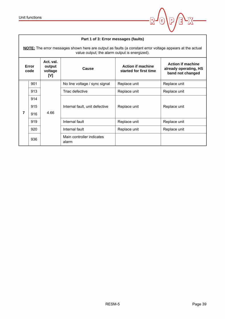
Part 1 of 3: Error messages (faults)
NOTE: The error messages shown here are output as faults (a constant error voltage appears at the actual value output; the alarm output is energized).
Error code
Act. val. output voltage
[V]
CauseAction if machine
started for first time
Action if machine already operating, HS
band not changed
1 101 0.66 No current signal Fault area Fault area
2
102
1.33
No voltage signal Fault area Fault area
118
Voltage signal has wrong polarity( section 7.3 "Wiring diagram" on page 17)
Reconnect/Interchange UR
measuring wire to terminals 8+9
Reconnect/Interchange UR
measuring wire to terminals 8+9
3103
2.00No current / voltage signals Fault area Fault areas
120 STANDBY test failed
4
107
2.66
Temperature step, down Fault areas (loose contact)
Fault areas (loose contact)108 Temperature step, up
109Maximum temperature exceeded
Check application Check application
307
Temperature too low / high308
309
310
5
201
3.33
Line frequency missing /fluctuates
Check power supply Check power supply202Line frequency too high / fluctuates
203Line frequency too low / fluctuates
6 304 4.00 Heatup time too long Run RESET Run RESET
Page 38 RESM-5
Unit functions
7
901
4.66
No line voltage / sync signal Replace unit Replace unit
913 Triac defective Replace unit Replace unit
914
Internal fault, unit defective Replace unit Replace unit915
916
919 Internal fault Replace unit Replace unit
920 Internal fault Replace unit Replace unit
936Main controller indicates alarm
Part 1 of 3: Error messages (faults)
NOTE: The error messages shown here are output as faults (a constant error voltage appears at the actual value output; the alarm output is energized).
Error code
Act. val. output voltage
[V]
CauseAction if machine
started for first time
Action if machine already operating, HS
band not changed
RESM-5 Page 39

Unit functions
Part 2 of 3: Error messages (warnings)
NOTE: The specified error messages are initially output as warnings (actual value output jumps back and forth between two values; alarm output is de-energized). When the "START" signal on the temperature controller is activated, the warning changes to a fault (actual value output no longer jumps back and forth, see bold italic
values; alarm output is energized).
Error code
Act. val. output voltage
[V]
CauseAction if machine
started for first time
Action if machine already operating, HS
band not changed
8
104
5.33 10
Current signal incorrect,incorrect specification of impulse transformer
Run AUTOCAL,check specification of transformer,
fault areas
Fault areas (loose contact)
105Voltage signal incorrect,incorrect specification of impulse transformer
106
Voltage and current signals incorrect,incorrect specification of impulse transformer
119Measurement pause too short during AUTOCAL
Run AUTOCAL, don't start controller
302
Temperature too low,calibration wasn't performed,loose contact,ambient temp. fluctuates
Run AUTOCALand / or
fault areas (loose contact)
303
Temperature too high,calibration wasn't performed,loose contact,ambient temp. fluctuates
9 2116.00 10
Data error Run AUTOCAL Run AUTOCAL
Page 40 RESM-5
Unit functions
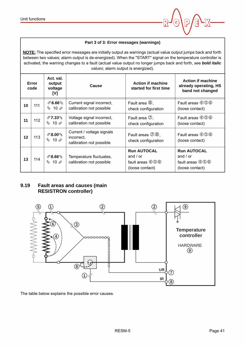
9.19 Fault areas and causes (main RESISTRON controller)
The table below explains the possible error causes.
Part 3 of 3: Error messages (warnings)
NOTE: The specified error messages are initially output as warnings (actual value output jumps back and forth between two values; alarm output is de-energized). When the "START" signal on the temperature controller is activated, the warning changes to a fault (actual value output no longer jumps back and forth, see bold italic
values; alarm output is energized).
Error code
Act. val. output voltage
[V]
CauseAction if machine
started for first time
Action if machine already operating, HS
band not changed
10 1116.66 10
Current signal incorrect,calibration not possible
Fault area ,
check configuration
Fault areas (loose contact)
11 1127.33 10
Voltage signal incorrect,calibration not possible
Fault area ,
check configuration
Fault areas (loose contact)
12 1138.00 10
Current / voltage signals incorrect,calibration not possible
Fault areas ,
check configuration
Fault areas (loose contact)
13 1148.66 10
Temperature fluctuates,calibration not possible
Run AUTOCALand / or
fault areas (loose contact)
Run AUTOCALand / or
fault areas (loose contact)
5
36
8
1
4
1 2 2 9
7
8
UR
IR
Temperaturecontroller
HARDWARE9
RESM-5 Page 41

Unit functions
Fault area Explanation Possible causes
Load circuit interrupted after UR
pickoff point
- Wire break, heatsealing band break- Contact to heatsealing band is defective
PEX-W2 / W3 current transformer signal interrupted
- IR measurement cable from current transformer interrupted
Primary circuit interrupted- Wire break, triac in controller defective- Primary winding of impulse transformer interrupted- Relay Kb opened
Secondary circuit interrupted before UR pickoff point
- Wire break- Secondary winding of impulse transformer interrupted
No UR signal - Measurement cable interrupted
Partial short-circuit (delta R)- Heatsealing band partially bypassed by conducting part
(clamp, opposite heatsealing bar etc.)
Parallel circuit interrupted- Wire break, heatsealing band break- Contact to heatsealing band is defective
Total short-circuit- Heatsealing band installed incorrectly, no insulation at
heatsealing bar ends or insulation incorrectly installed- Heatsealing band completely bypassed by conducting part
UR signal incorrect - U2 outside of permissible range from 0.4…120VAC
IR signal incorrect - I2 outside of permissible range from 30…500A
Wire incorrectly laid through PEX-W2 / W3 current transformer
- Check number of times wire is laid through (minimum of twice required for currents < 30A)
Internal unit fault - Hardware fault (replace unit)
Page 42 RESM-5
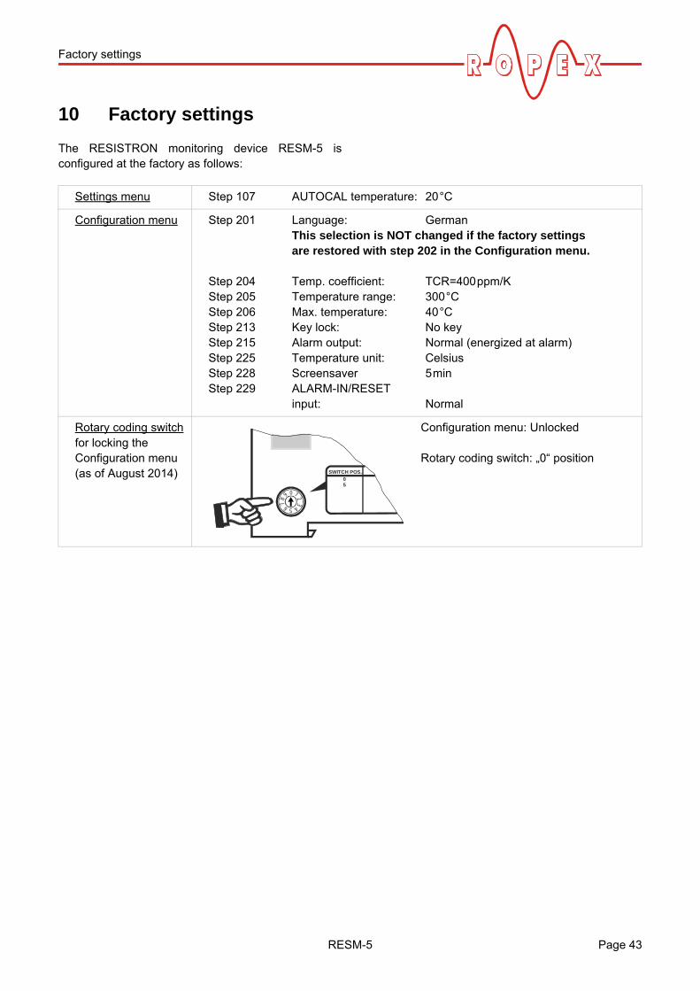
Factory settings
10 Factory settings
The RESISTRON monitoring device RESM-5 isconfigured at the factory as follows:
Settings menu Step 107 AUTOCAL temperature: 20°C
Configuration menu Step 201 Language: GermanThis selection is NOT changed if the factory settingsare restored with step 202 in the Configuration menu.
Step 204 Temp. coefficient: TCR=400ppm/KStep 205 Temperature range: 300°CStep 206 Max. temperature: 40°CStep 213 Key lock: No keyStep 215 Alarm output: Normal (energized at alarm)Step 225 Temperature unit: CelsiusStep 228 Screensaver 5minStep 229 ALARM-IN/RESET
input: Normal
Rotary coding switchfor locking theConfiguration menu(as of August 2014)
Configuration menu: Unlocked
Rotary coding switch: „0“ positionSWITCH POS.
50
0
5
1 234678
9
RESM-5 Page 43

Maintenance
10.1 Customer settings
The unit's factory settings can be defined or restoredwith step 202 in the Configuration menu. You can storecustomer settings in addition to the Ropex settings:
The following settings are possible:
1. "Restore Ropex settings"(factory setting)By choosing this option, you restore the valueslisted in section 10 "Factory settings" on page 43.These values correspond to the factory settings withwhich the unit was shipped.
2. "Define customer settings"By choosing this option, you save the values thatare currently defined in the unit's Settings andConfiguration menus as "customer settings". These"customer settings" are independent of the Ropexsettings. Machine-specific settings can be stored inthe unit in this way.
3. "Restore customer settings"By choosing this option, you restore the "customersettings" that were defined as described in 2.
When the unit is shipped, the "customersettings" are identical to the Ropex settings.
After pressing the "ENTER" key in this menu, you areasked to confirm the new settings (safety query).
If you confirm these settings by pressing the "ENTER"key for approximately 2seconds, you then see anothermessage.
You can also cancel the new settings by pressing the"MENU", cursor "UP", or cursor "DOWN" keys.Step 203 then appears on the display.
The language selected with step 201 in theConfiguration menu remains set if the
previous settings are restored.
11 Maintenance
The unit requires no special maintenance. Regularinspection and / or tightening of the terminals isrecommended. Dust deposits on the unit can beremoved with dry compressed air.
To prevent dangerous situations, refer to therisk analysis for the machine or plant (e.g.
carry out regular functional tests).
!
!
!
Page 44 RESM-5

How to order
12 How to order
For more accessories: "Accessories" leaflet
RESM - 5/ . . . V AC115: Power supply 115VAC, Art. No. 885241230: Power supply 230VAC, Art. No. 885242400: Power supply 400VAC, Art. No. 885243
Scope of supply: Unit includes connector plug-in parts(current transformer must be ordered
separately)
Modification MOD . . (optional, if required)e.g.01: MOD 01, Art. No. 800001 (booster for low voltage)
Please indicate the article numbers of the unit and the required modifications(optional) in all orders,
e.g. RESM-5/400VAC + MOD 01(unit for 400VAC power supplywith booster for low voltage)Art. Nos. 885243 + 800001 must be ordered
Current transformer PEX-W3Art. No. 885105
Line filter LF- . . 48006: Continuous current 6A, 480VAC, Art. No. 88550035: Continuous current 35A, 480VAC, Art. No. 885506
Communication interface CI-USB-1Art. No. 885650
Temp. meter ATR- .3: 300°C range, Art. No. 8821305: 500°C range, Art. No. 882150
RESM-5 Page 45

Index
13 Index
AAccessories 11Actual value output 31Alarm output 12, 19, 36"ALARM-IN" signal 33Alloy 19, 21Ambient temperature 12Analog input 12Analog output 12Analog temperature meter 11Application 4Application Report 14AUTOCAL 21, 32Automatic zero calibration 21, 32Auxiliary voltage 12
BBooster connection 36Burning in heatsealing band 20, 21
CCelsius °C 34CI-USB-1 11, 36, 45Communication interface 11, 36, 45Controls 22Current transformer 11, 45Customer settings 44
DDegree of protection 12Diagnostic interface 36Dimensions 13, 14Disable Configuration menu 34Display 23Display brightness 35
EError diagnosis 36
FFactory settings 19, 43Fahrenheit °F 34Fault areas 41
HHeatsealing band type 12
IInstallation 13, 14Installation procedure 14Installation regulations 14
LLine filter 11, 45Line frequency 12Line voltage 12
MMaintenance 44"MAN" key locked 33Maximum temperature set point 31Measurement cable 11Measuring range 12Modifications 11, 45MODs 11, 45Monitoring current transformer 11Monitoring temperature 31
PPEX-W2/-W3 3PEX-W3 45Power dissipation 12Power supply system 12Principle 5
RReplacing heatsealing band 20Replacing the heatsealing band 21"RESET" signal 33Rotary coding switch 35, 43
SStandby mode 35System diagnosis 36System monitoring 36
TTCR 3, 20Temperature coefficient 3, 19, 20Temperature meter 11, 31, 32, 45Temperature range 12, 19Temperature unit 34Transformer 3Type of construction 12
UUndervoltage detection 35Unit configuration 18
VView of the unit 18Visualization software 36
Page 46 RESM-5

Index
WWiring 14
Wiring diagram 17
RESM-5RESM-5 Page 47