resistomat model 2302-v001 - j and b€¦ · applications ... digital voltmeter ... resistomat®...
TRANSCRIPT
Model 2302-V001RESISTOMAT®
Page 1
Bri
efg
uid
eO
per
atio
nC
alib
rati
on
Tes
t an
d o
ffse
tin
stru
ctio
ns
RS
232
dat
ao
utp
ut
Intr
od
uct
ion
&ap
plic
atio
ns
Des
crip
tio
no
f fu
nct
ion
sA
cces
sori
es a
nd
Cir
cuit
dia
gra
m
© 2004 bursterpräzisionsmeßtechnik gmbh & co kgAll rights reservedVersion: 18.03.2004
Manufacturer:burster präzisionsmeßtechnik gmbh & co kgTalstraße 1 - 5 BOX 143276593 Gernsbach 76587 Gernsbach
RESISTOMAT®
Model 2302-V001
Note:The information contained in the following is subject to change without prior notice. No part of this documentmust be reproduced or processed using electronic systems without prior, written approval.
burster does not provide any type of warranty for this device, including any implicit warranty concerning itsgeneral quality or suitability for a particular purpose.burster assumes no liability whatsoever for errors, incidental damage or consequential damage arising duringthe operation of this device.

RESISTOMAT®Model 2302-V001
Page 2
Intr
od
uct
ion
&ap
plic
atio
ns
Des
crip
tio
no
f fu
nct
ion
sB
rief
gu
ide
Op
erat
ion
Cal
ibra
tio
nT
est
and
off
set
inst
ruct
ion
sR
S23
2 d
ata
ou
tpu
tA
cces
sori
es a
nd
Cir
cuit
dia
gra
m

Model 2302-V001RESISTOMAT®
Page 3
Bri
efg
uid
eO
per
atio
nC
alib
rati
on
Tes
t an
d o
ffse
tin
stru
ctio
ns
RS
232
dat
ao
utp
ut
Intr
od
uct
ion
&ap
plic
atio
ns
Des
crip
tio
no
f fu
nct
ion
sA
cces
sori
es a
nd
Cir
cuit
dia
gra
m

RESISTOMAT®Model 2302-V001
Page 4
Intr
od
uct
ion
&ap
plic
atio
ns
Des
crip
tio
no
f fu
nct
ion
sB
rief
gu
ide
Op
erat
ion
Cal
ibra
tio
nT
est
and
off
set
inst
ruct
ion
sR
S23
2 d
ata
ou
tpu
tA
cces
sori
es a
nd
Cir
cuit
dia
gra
m
Overview of contents
Model 2302-V001RESISTOMAT®
Page 5
Bri
efg
uid
eO
per
atio
nC
alib
rati
on
Tes
t an
d o
ffse
tin
stru
ctio
ns
RS
232
dat
ao
utp
ut
Intr
od
uct
ion
&ap
plic
atio
ns
Des
crip
tio
no
f fu
nct
ion
sA
cces
sori
es a
nd
Cir
cuit
dia
gra
m
PagesIntroduction and applications..................................................................... 7Introduction..................................................................................................... 7Four-wire resistance measurement................................................................ 8Applications.................................................................................................... 10
Description of functions.............................................................................. 11General information........................................................................................ 11Current source................................................................................................ 11Digital voltmeter.............................................................................................. 12
Brief guide..................................................................................................... 13
Operation....................................................................................................... 15Mains connection........................................................................... 15Power-on....................................................................................... 15Warm-up period............................................................................ 15Zero setting................................................................................... 15Absolute value measurement........................................................ 15Temperature compensation.......................................................... 16Temperature compensation accuracy........................................... 16Measurement range selection....................................................... 16Connecting the test unit................................................................. 17Shielding........................................................................................ 18Signal lamp for line resistance RL.................................................. 18Range transgression..................................................................... 19RS232 output................................................................................ 19Special interferences in the case of cable drums.......................... 19Test units with a large inductive proportion................................... 20
Calibration..................................................................................................... 21
Test and offset instructions........................................................................ 23
RS232 data output........................................................................................ 27Pin assignment and configuration................................................ 27Protocol description....................................................................... 28Instructions for identification and protocol parametrization........... 31Instructions for requesting measurement values andidentifying faults............................................................................. 36Instructions for device control........................................................ 39Sample program for IBM-PC......................................................... 43
Schaltungsunternlagen and Accessories.................................................. 45Circuit diagram................................................................... 45Accessories................................................................................... 49Calibration resistor..........................................................................49Clamping device............................................................................ 51Kelvin test tongs/testprobes.......................................................... 53
Overview of contents

RESISTOMAT®Model 2302-V001
Page 6
Intr
od
uct
ion
&ap
plic
atio
ns
Des
crip
tio
no
f fu
nct
ion
sB
rief
gu
ide
Op
erat
ion
Cal
ibra
tio
nT
est
and
off
set
inst
ruct
ion
sR
S23
2 d
ata
ou
tpu
tA
cces
sori
es a
nd
Cir
cuit
dia
gra
m
Model 2302-V001RESISTOMAT®
Page 7
Bri
efg
uid
eO
per
atio
nC
alib
rati
on
Tes
t an
d o
ffse
tin
stru
ctio
ns
RS
232
dat
ao
utp
ut
Intr
od
uct
ion
&ap
plic
atio
ns
Des
crip
tio
no
f fu
nct
ion
sA
cces
sori
es a
nd
Cir
cuit
dia
gra
m
Introduction
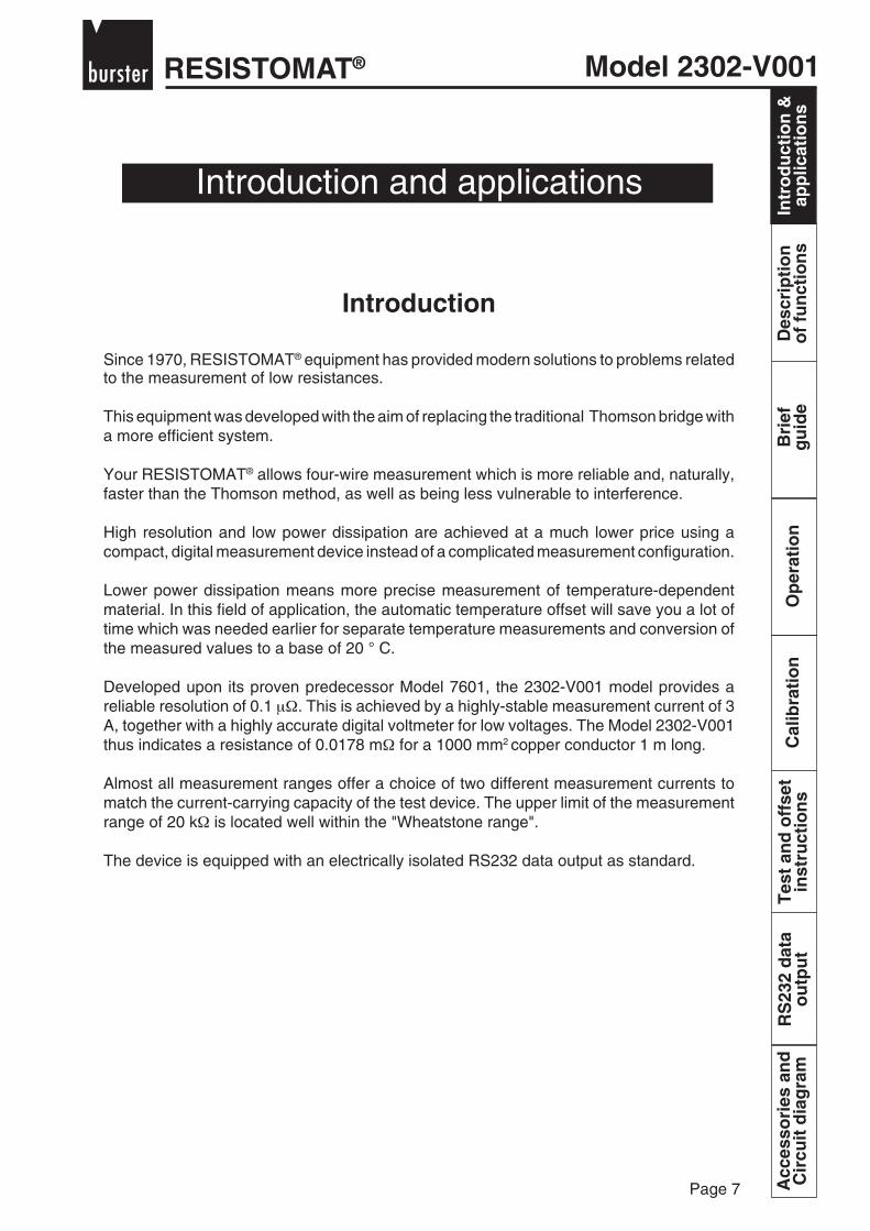
Since 1970, RESISTOMAT® equipment has provided modern solutions to problems relatedto the measurement of low resistances.
This equipment was developed with the aim of replacing the traditional Thomson bridge witha more efficient system.
Your RESISTOMAT® allows four-wire measurement which is more reliable and, naturally,faster than the Thomson method, as well as being less vulnerable to interference.
High resolution and low power dissipation are achieved at a much lower price using acompact, digital measurement device instead of a complicated measurement configuration.
Lower power dissipation means more precise measurement of temperature-dependentmaterial. In this field of application, the automatic temperature offset will save you a lot oftime which was needed earlier for separate temperature measurements and conversion ofthe measured values to a base of 20 ° C.
Developed upon its proven predecessor Model 7601, the 2302-V001 model provides areliable resolution of 0.1 µΩ. This is achieved by a highly-stable measurement current of 3A, together with a highly accurate digital voltmeter for low voltages. The Model 2302-V001thus indicates a resistance of 0.0178 mΩ for a 1000 mm2 copper conductor 1 m long.
Almost all measurement ranges offer a choice of two different measurement currents tomatch the current-carrying capacity of the test device. The upper limit of the measurementrange of 20 kΩ is located well within the "Wheatstone range".
The device is equipped with an electrically isolated RS232 data output as standard.
Introduction and applications
Intr
od
uct
ion
&ap
plic
atio
ns

RESISTOMAT®Model 2302-V001
Page 8
Intr
od
uct
ion
&ap
plic
atio
ns
Des
crip
tio
no
f fu
nct
ion
sB
rief
gu
ide
Op
erat
ion
Cal
ibra
tio
nT
est
and
off
set
inst
ruct
ion
sR
S23
2 d
ata
ou
tpu
tA
cces
sori
es a
nd
Cir
cuit
dia
gra
m
- I
RX
RLI
RLI
RLU
RLU
+ U
- U
+ I
Intr
od
uct
ion
&ap
plic
atio
ns
Four-wire resistance measurement
If you have ever used a Thomson bridge, you must have noticed occasional interferencecaused by supply-line resistances, though popular opinion has it that the influence of theselines should be negligible.Actually, it is negligible only as long as the line resistances do not exceed a certain, very lowlimit; this applies particularly to the connection between the reference or standard resistanceRN (sketch) and the object under test RX.An awkward side-effect of this is that resulting errors can go unnoticed.
RESISTOMAT® equipment incorporating the constant current/voltage drop technique doesnot cause such problems.
Figure 1: Thomson bridge
RL can influence the result
Model 2302-V001RESISTOMAT®
Page 9
Bri
efg
uid
eO
per
atio
nC
alib
rati
on
Tes
t an
d o
ffse
tin
stru
ctio
ns
RS
232
dat
ao
utp
ut
Intr
od
uct
ion
&ap
plic
atio
ns
Des
crip
tio
no
f fu
nct
ion
sA
cces
sori
es a
nd
Cir
cuit
dia
gra
m
I = const.
RLU
+ U- U
+ I- I
RX
RLI RLI
DVM
RL beeinflusst Ergebnis nicht
Intr
od
uct
ion
&ap
plic
atio
ns
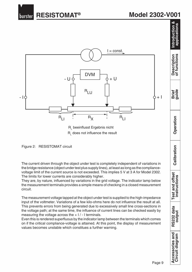
RL does not influence the result
Figure 2: RESISTOMAT circuit
The current driven through the object under test is completely independent of variations inthe bridge resistance (object under test plus supply lines), at least as long as the compliance-voltage limit of the current source is not exceeded. This implies 5 V at 3 A for Model 2302.The limits for lower currents are considerably higher.They are, by nature, influenced by variations in the grid voltage. The indicator lamp belowthe measurement terminals provides a simple means of checking in a closed measurementcircuit.
The measurement voltage tapped at the object under test is supplied to the high-impedanceinput of the voltmeter. Variations of a few kilo-ohms here do not influence the result at all.This prevents errors from being generated due to excessively small line cross-sections inthe voltage path; at the same time, the influence of current lines can be checked easily bymeasuring the voltage across the + I / - I terminals.Even this is rendered superfluous by the indicator lamp between the terminals which comeson if the critical compliance-voltage is attained. At this point, the display of measurementvalues becomes unstable which constitues a further warning.
RESISTOMAT®Model 2302-V001
Page 10
Intr
od
uct
ion
&ap
plic
atio
ns
Des
crip
tio
no
f fu
nct
ion
sB
rief
gu
ide
Op
erat
ion
Cal
ibra
tio
nT
est
and
off
set
inst
ruct
ion
sR
S23
2 d
ata
ou
tpu
tA
cces
sori
es a
nd
Cir
cuit
dia
gra
mIn
tro
du
ctio
n &
app
licat
ion
s
Applications
Originally developed for monitoring conductances during the manufacture and final testingof high-tension cables, RESISTOMAT® equipment later took on a significance in many otherareas, involving not only Thomson measurements but also, to a large extent, classicalWheatstone measurements.
This equipment has the following applications in the cable industry:
- Resistance measurements of meter-samples, ranging from the smallest tothe largest cross-sections
- Conductivity checks in stranding(in conjunction with automatic control)
- Final acceptance of cable drums
In laboratories for testing motors and transformers, RESISTOMAT® equipment is used tomeasure coil resistance and heating (thermal co-efficient of resistance) and for testing thequality of welded joints on commutators.The RESISTOMAT® also proves useful in metallurgical investigations based on resistancemeasurement.
Statistical quality control with computerized evaluation only became efficient on introductionof the RESISTOMAT® with an RS232-C output allowing fast measurement sequences.The number of samples has been increased five-fold compared with the traditional method,without the need for qualified personnel to perform measurement tasks.
If you obtain some unkown resistance, you can quickly read off its value up to a maximumof 20 kΩ on your RESISTOMAT® .Simply connect it to + U / - U, and link + U / + I and - U / - I. Usually, the wire ends on the testobject are sufficient for this.
Highly accurate temperature measurements are also possible with the RESISTOMAT® .A Pt-100 sensor provides readings to an accuracy of 10 mΩ, even 1 mΩ for lowtemperatures, at a sensor current of 1 mA.
Last but not least, the RESISTOMAT® serves as a precise and highly stable current sourcewhich can be used separately for calibrating moving-coil instruments or other poweredmeasuring devices; it also serves as a precision, high-resolution digital voltmeter for lowvoltages (max. 0.5 V final value) . This allows the measurement and testing of thermal e.m.fsand mV sources. e.g. the thermocouple simulator made by burster präzisionsmeßtechnik.
Model 2302-V001RESISTOMAT®
Page 11
Bri
efg
uid
eO
per
atio
nC
alib
rati
on
Tes
t an
d o
ffse
tin
stru
ctio
ns
RS
232
dat
ao
utp
ut
Intr
od
uct
ion
&ap
plic
atio
ns
Des
crip
tio
no
f fu
nct
ion
sA
cces
sori
es a
nd
Cir
cuit
dia
gra
m
Description of functions
Des
crip
tio
no
f fu
nct
ion
s
General information
The principle of current and voltage measurement for resistances is initially represented bytwo completely separate blocks of functions:
The multi-range constant-voltage source and the highly-sensitive digital voltmeter.Both components are controlled via coupled switches which comprise the rangeselector on the front panel.The measuring current and voltage sensitivity are matched together so as toprovide readings directly in mΩ or Ω in accordance with Ohm's law using thedecimal point and units lamps which are also controlled.
Current source
An electronic control circuit supplies the current which was set and displayed using the rangeselector, as soon as the external current path is closed. The currents are calibrated withinthe overall limits of accuracy of the device; fluctuations caused by interfering factors (mainsvoltage, load) are smaller than 0.001 % or 0.003 % in the worst case; consequently, thehighest possible indicated resistance of 20.000 would fluctuate by just one digit (given astable test unit).
However, current sources also have driving voltages which impose a limit on the voltagedrop across the load resistance.
The current generator also contains the automatic temperature compensation for coppertest units. When the mode switch is on the appropriate setting, the current changeswith the temperature of the test unit such that the voltage drop across the latter alwayscorresponds to the value for 20°C.
The compensating signal for the current is supplied continually by a Model 2391 sensor.
3
RESISTOMAT®Model 2302-V001
Page 12
Intr
od
uct
ion
&ap
plic
atio
ns
Des
crip
tio
no
f fu
nct
ion
sB
rief
gu
ide
Op
erat
ion
Cal
ibra
tio
nT
est
and
off
set
inst
ruct
ion
sR
S23
2 d
ata
ou
tpu
tA
cces
sori
es a
nd
Cir
cuit
dia
gra
m
11 1 24
38
597
6
1012
Des
crip
tio
no
f fu
nct
ion
s
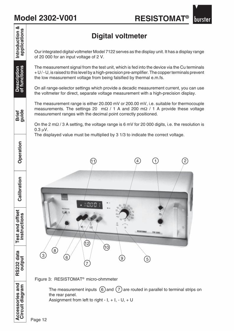
Figure 3: RESISTOMAT® micro-ohmmeter
The measurement inputs and are routed in parallel to terminal strips onthe rear panel.Assignment from left to right - Ι, + Ι, - U, + U
Digital voltmeter
Our integrated digital voltmeter Model 7122 serves as the display unit. It has a display rangeof 20 000 for an input voltage of 2 V.
The measurement signal from the test unit, which is fed into the device via the Cu terminals+ U / - U, is raised to this level by a high-precision pre-amplifier. The copper terminals preventthe low measurement voltage from being falsified by thermal e.m.fs.
On all range-selector settings which provide a decadic measurement current, you can usethe voltmeter for direct, separate voltage measurement with a high-precision display.
The measurement range is either 20.000 mV or 200.00 mV, i.e. suitable for thermocouplemeasurements. The settings 20 mΩ / 1 A and 200 mΩ / 1 A provide these voltagemeasurement ranges with the decimal point correctly positioned.
On the 2 mΩ / 3 A setting, the voltage range is 6 mV for 20 000 digits, i.e. the resolution is0.3 µV.The displayed value must be multiplied by 3 1/3 to indicate the correct voltage.
6 7

Model 2302-V001RESISTOMAT®
Page 13
Bri
efg
uid
eO
per
atio
nC
alib
rati
on
Tes
t an
d o
ffse
tin
stru
ctio
ns
RS
232
dat
ao
utp
ut
Intr
od
uct
ion
&ap
plic
atio
ns
Des
crip
tio
no
f fu
nct
ion
sA
cces
sori
es a
nd
Cir
cuit
dia
gra
m
Brief guide
Bri
efg
uid
e
Mains toggle switch
Mains fuse1 A for 220 V operation2 A for 115 V operation
Selector switch for activating/deactivating temperature compensation
Range selector providing a choice of two different measurement currents formost ranges. Select the higher current whenever permissible.
Zero potentiometer for voltmeter section
Voltmeter input (potential leads from the test unit).
Measurement current output
Connection for an external temperature sensor (Cu sensor Model 2391)
Calibration trimmer P 1 (current calibration)
Warning lamp for excessively high supply-line resistances or interruptions inthe current path (measurement current no longer stable).
Digital display: Complete readings with decimal point and unit are alwaysprovided.
Grounding socket
1
2
3
4
5
6
7
8
9
10
11
12

RESISTOMAT®Model 2302-V001
Page 14
Intr
od
uct
ion
&ap
plic
atio
ns
Des
crip
tio
no
f fu
nct
ion
sB
rief
gu
ide
Op
erat
ion
Cal
ibra
tio
nT
est
and
off
set
inst
ruct
ion
sR
S23
2 d
ata
ou
tpu
tA
cces
sori
es a
nd
Cir
cuit
dia
gra
m
Model 2302-V001RESISTOMAT®
Page 15
Bri
efg
uid
eO
per
atio
nC
alib
rati
on
Tes
t an
d o
ffse
tin
stru
ctio
ns
RS
232
dat
ao
utp
ut
Intr
od
uct
ion
&ap
plic
atio
ns
Des
crip
tio
no
f fu
nct
ion
sA
cces
sori
es a
nd
Cir
cuit
dia
gra
m
Operation
Op
erat
ion
Mains connection
If not otherwise requested, we supply the device for 230 V/50 Hz operation. Ensure that thecorrect operating voltage is supplied. The maximum permissible deviation from the ratedvalue is + 6 %, - 10 %.Alternatively, an operating voltage of 115 V/ 50 Hz or 60 Hz is also possible.
Power-on
Pressing switch activates the display and the units symbol. If the ± U input is open, thedisplayed value drifts in an undefined manner, possibly exceeding 20 000 and starting toflash as a result.
Warm-up period
Within 30 seconds following power-on, you can start performing measurements to anaccuracy of 0.1 %, although between 10 and 15 minutes could pass before the final accuracyis attained. If the lowest measurement range is selected and the U-terminals are short-circuited, you will notice a zero drift of approximately 10 digits after power-on.
Zero setting
With the U-terminals short-circuited (clamped Cu wire - open current output) set the displayto 0 in the smallest measurement range using the potentiometer .The potentiometer can be locked with the lateral lever.
For more precise measurements in low ranges, it is advisable to perform the zero setting withthe test object connected but de-energized. This allows the compensation of small errorswhich might be caused by thermal e.m.fs in the measurement circuit.
Absolute value measurement
If switch is in the off position, the absolute value of the connected test object, i.e. theactual, existing value, is displayed.
3
5
1
RESISTOMAT®Model 2302-V001
Page 16
Intr
od
uct
ion
&ap
plic
atio
ns
Des
crip
tio
no
f fu
nct
ion
sB
rief
gu
ide
Op
erat
ion
Cal
ibra
tio
nT
est
and
off
set
inst
ruct
ion
sR
S23
2 d
ata
ou
tpu
tA
cces
sori
es a
nd
Cir
cuit
dia
gra
mO
per
atio
n
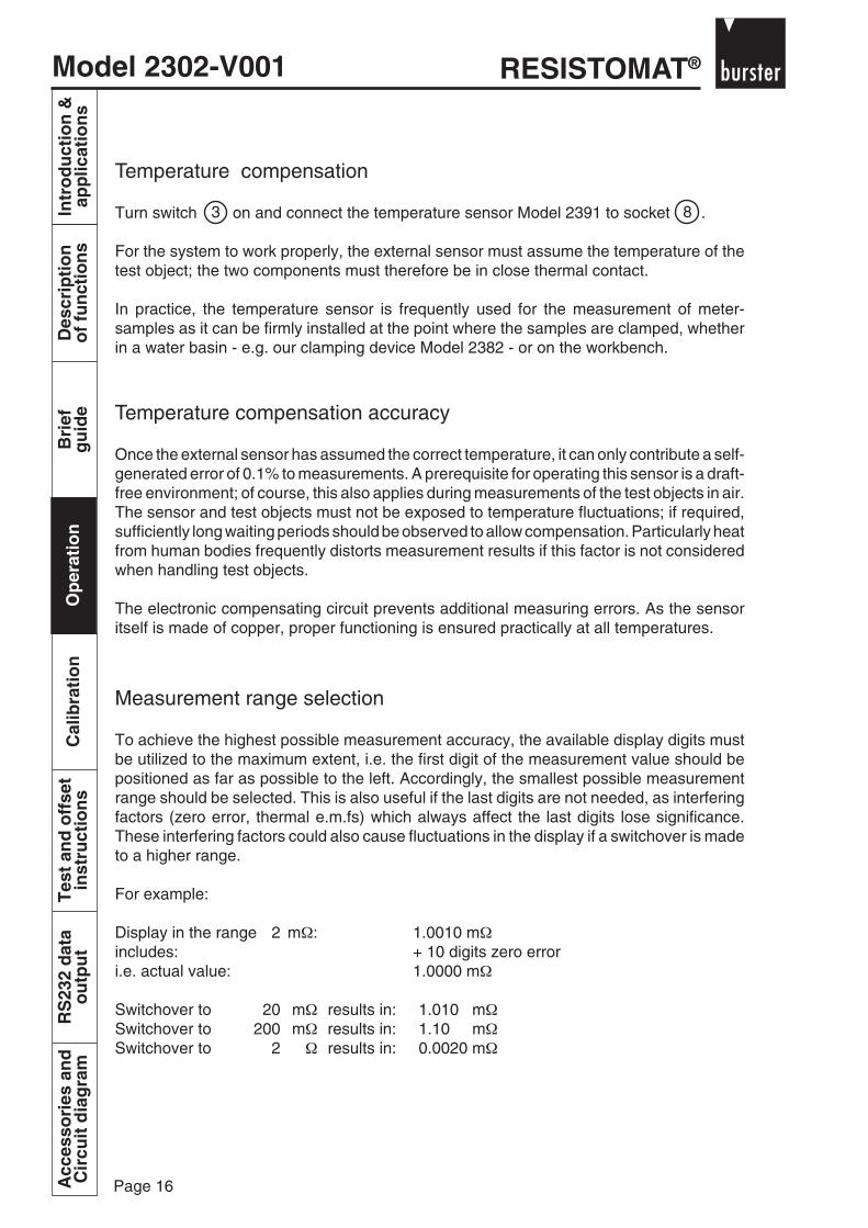
Temperature compensation
Turn switch on and connect the temperature sensor Model 2391 to socket .
For the system to work properly, the external sensor must assume the temperature of thetest object; the two components must therefore be in close thermal contact.
In practice, the temperature sensor is frequently used for the measurement of meter-samples as it can be firmly installed at the point where the samples are clamped, whetherin a water basin - e.g. our clamping device Model 2382 - or on the workbench.
Temperature compensation accuracy
Once the external sensor has assumed the correct temperature, it can only contribute a self-generated error of 0.1% to measurements. A prerequisite for operating this sensor is a draft-free environment; of course, this also applies during measurements of the test objects in air.The sensor and test objects must not be exposed to temperature fluctuations; if required,sufficiently long waiting periods should be observed to allow compensation. Particularly heatfrom human bodies frequently distorts measurement results if this factor is not consideredwhen handling test objects.
The electronic compensating circuit prevents additional measuring errors. As the sensoritself is made of copper, proper functioning is ensured practically at all temperatures.
Measurement range selection
To achieve the highest possible measurement accuracy, the available display digits mustbe utilized to the maximum extent, i.e. the first digit of the measurement value should bepositioned as far as possible to the left. Accordingly, the smallest possible measurementrange should be selected. This is also useful if the last digits are not needed, as interferingfactors (zero error, thermal e.m.fs) which always affect the last digits lose significance.These interfering factors could also cause fluctuations in the display if a switchover is madeto a higher range.
For example:
Display in the range 2 mΩ: 1.0010 mΩincludes: + 10 digits zero errori.e. actual value: 1.0000 mΩ
Switchover to 20 mΩ results in: 1.010 mΩSwitchover to 200 mΩ results in: 1.10 mΩSwitchover to 2 Ω results in: 0.0020 mΩ
83

Model 2302-V001RESISTOMAT®
Page 17
Bri
efg
uid
eO
per
atio
nC
alib
rati
on
Tes
t an
d o
ffse
tin
stru
ctio
ns
RS
232
dat
ao
utp
ut
Intr
od
uct
ion
&ap
plic
atio
ns
Des
crip
tio
no
f fu
nct
ion
sA
cces
sori
es a
nd
Cir
cuit
dia
gra
mO
per
atio
n
Evidently, the display is heavily distorted in the higher ranges due to the inclusion of the zeroerror.The most accurate display is provided in the 2 mΩ range.
After determining a suitable measurement range, you must decide whether it is permissiblefor the test object to be loaded by the current stated on the left half of the switch's scale.If no falsification resulting from heating is involved, you should select the higher current forthe resistance range in question. It generates the higher measurement signal, thus reducingthe potential of interference by the zero error and thermal e.m.fs.
The standard maximum measurement currents for a copper wire with a cross-section of 1.5mm2 are 1 A in air and 3A in water (1m has approx. 12 mΩ, so the 50 mΩ range is suitablehere).
Connecting the test object
As shown in Section 2, route the voltage terminals + U / - U to the ends of the actualmeasurement path.The current connections on the test object should be placed far enough from the potentialtaps to allow an even distribution of the measurement current up to the potential taps,otherwise the resistance value determined is higher than the actual resistance of the path(the current is concentrated over a smaller cross-section).
For stranded copper conductors, it is not necessary to make contact with every single wire,as the mutual contact between these wires is sufficient. However, this property and thus theU-I spacing of the measurement connections is slightly dependent on the strand density.Experience has shown that for cross-sections of more than 300 mm2, a path of 80 cmbetween the U and I terminals is required on both sides.
Pressed-on wedge bonds are suitable as potential taps. If the current is distributed evenly,contact with the entire circumference of the test object is not required, as the tangentialpotential is the same everywhere.The cross-sections of the potential leads routed to the RESISTOMAT® device do notsignificantly influence the measurement.
The current path must be configured such that the voltage drops listed in the table below arenot exceeded; this is to ensure that the current remains stable.To be on the safe side, the values for mains undervoltage will be considered.
Of course, these voltage values are much higher than the values measured directly on thetest object. This, for example, also allows a series connection of several test objects withchangevoer of the potential taps.
2302
Mains voltage 3 A 1 A
- 10 % 4 V 6 V
Rated value 5 V 7 V
+ 6 % 6 V 8 V

RESISTOMAT®Model 2302-V001
Page 18
Intr
od
uct
ion
&ap
plic
atio
ns
Des
crip
tio
no
f fu
nct
ion
sB
rief
gu
ide
Op
erat
ion
Cal
ibra
tio
nT
est
and
off
set
inst
ruct
ion
sR
S23
2 d
ata
ou
tpu
tA
cces
sori
es a
nd
Cir
cuit
dia
gra
mO
per
atio
n
Figure 4: Measurement of contact resistances on switches
At this point, we would like to refer to our clamping devices Model 2381 and Model 2382which are meant for operation in air and water respectively and ensure proper contact withyour samples.
Another possible connection shown below involves the measurement of contact resistanceson switches.
The occurrence of thermal e.m.fs in the voltage path must be prevented; this appliesparticularly in the case of the smallest measurement ranges.
If all connections are made with copper or brass parts (not galvanized!), no majorfalsifications can be expected.
Pole reversal in the current or voltage leads results in displays prefixed with a negative sign,although this is purely a "cosmetic" error.
Shielding
Normally, measuring leads in laboratories are routed openly. This would only createproblems if heavy interference were generated, e.g. by varying magnetic fields.If an experiment with unshielded leads does not proceed satisfactorily, it is advisable toenclose the leads in seamless, grounded steel tubes where large distances are invloved.50 Hz interference, which is present practically everywhere, is filtered out by the input circuitof the RESISTOMAT®.
Signal lamp for line resistance (RL)
Located below the measurement terminals, this lamp comes on if the voltage drop in theexternal current path reaches a critical value at which the current stabilization is no longereffective. This indicates an excessively high line resistance RL or an interruption.When this lamp is on, the measured values are incorrect!
+ U- U + I- I

Model 2302-V001RESISTOMAT®
Page 19
Bri
efg
uid
eO
per
atio
nC
alib
rati
on
Tes
t an
d o
ffse
tin
stru
ctio
ns
RS
232
dat
ao
utp
ut
Intr
od
uct
ion
&ap
plic
atio
ns
Des
crip
tio
no
f fu
nct
ion
sA
cces
sori
es a
nd
Cir
cuit
dia
gra
mO
per
atio
n
Range transgression
This display flashes if a value of 20 000 is exceeded, i.e. if the selected measurement rangeis too small.This does not necessarily mean that the RL display lights up as well, as the voltage acrossthe current terminals is much larger than the maximum value of the measurement voltage+ U / - U.
RS232 output
The terminal assignments on the 25-pole socket are:
Assignment: Pin 1 ShieldPin 2 RxDPin 3 TxDPin 4 RTSPin 7 SGND
Special inteferences in the case of cable drums and their elimination
Cable drums comprise highly inductive coils. When placed in fluctuating magnetic fields,they generate correspondingly fluctuating voltages which are superimposed on themeasurement signal, thus leading to an unstable display.Intefering voltages of the mains frequency, also detected everywhere possible, are not verycritical as they are filtered out by the RESISTOMAT® .
In contrast, passing cranes and fork-lifts generate interfering voltages of a very lowfrequency which can disrupt any measurement. There is no possibility of shielding againstthis kind of interference, apart from a magnetically sealed cage, which is not feasible.
As an initial measure to suppress these effects, select the highest possible measurementcurrent to widely separate the effective and interfering components of the signal.In this manner, the problem can frequently be remedied using RESISTOMAT® equipment.In the case of multi-core leads, there are two other methods of overcoming these difficulties:
1. While one conductor is being measured, short-circuit the otherstogether - proper contact must be made in this process. Thismay reduce the inductance of the entire drum to such an extentso as to make the interference negligible.

RESISTOMAT®Model 2302-V001
Page 20
Intr
od
uct
ion
&ap
plic
atio
ns
Des
crip
tio
no
f fu
nct
ion
sB
rief
gu
ide
Op
erat
ion
Cal
ibra
tio
nT
est
and
off
set
inst
ruct
ion
sR
S23
2 d
ata
ou
tpu
tA
cces
sori
es a
nd
Cir
cuit
dia
gra
mO
per
atio
n
However, three such measurements should be performedusing the three possible wire combinations and the individualvalues calculated as follows:
This method takes slightly more time but is least prone to interferences.
Test objects with a large inductive proportion
Measurements performed on large inductances (e.g. cable wound around steel drums orpower transformers) involve the problem of considerably high, self-induced voltages oninterruption of the measurement current. Although the RESISTOMAT® Model 2302 has aprotective input circuit, damage might nevertheless be caused by very high voltage peaks.
The Model 2371 protective switchover unit solves this problem. On the "contact" switchsetting, both the current and potential lines are bridged, thus short-circuiting the self-inducedvoltages.
Attention! Measurement ranges must only be switched over onthe "contact" setting (i.e. the current and potentiallines must be short-circuited).
Simply connect the Model 2371 protective switchover unit in parallel with the test object tothe terminals of the Model 2302 RESISTOMAT®.
R1 = R2 = R3 =A - B + C A + B - C B - A + C
2 2 2
A = R1 + R2 B = R2 + R3 C = R1 + R3
2. Also based on a reduction of inductance, the following method is very suitablefor three-wire cables:
Connect two wires at one end of the drum to theRESISTOMAT® and join them together at the otherend so that these wires are measured in a seriesconnection.As these two wires are connected in opposition,(bifilar winding), this results in hardly any inductanceand, therfore, an immunity to magnetic interference.
Model 2302-V001RESISTOMAT®
Page 21
Bri
efg
uid
eO
per
atio
nC
alib
rati
on
Tes
t an
d o
ffse
tin
stru
ctio
ns
RS
232
dat
ao
utp
ut
Intr
od
uct
ion
&ap
plic
atio
ns
Des
crip
tio
no
f fu
nct
ion
sA
cces
sori
es a
nd
Cir
cuit
dia
gra
m
Calibration
Cal
ibra
tio
n
You can test the calibration of your RESISTOMAT® micro-ohmmeter at any time by correctlyconnecting standard or calibration resistances.
Suitable types which can be easily connected to the measurement terminals using the Type2394 adapter are available in accordance with our specifications sheet 1240.
For accurate testing, a resistance providing a display of at least 10,000 should be availablefor each measuring range.
If an uncertainty factor of ± 0.1 % is sufficient, a "1" value can be used to test two adjacentranges which then provide a display of 10,000 and 1,000 respectively.
The trimmer on the front panel allows general re-calibrations of the device, actingproportionally on all measurement currents. Adjustments can thus be made here if all rangesprovide uniformly inaccurate results, or even if particularly high accuracy is required for acertain range whereas the others are not as significant.
For any one of the following errors however, the test and offset procedure described onpages 6-1- to 6-4 must be used:
Individual range is faulty
Error cannot be corrected with trimmer
Unstable display with connected calibration resistance
Corrections with the trimmer do not require any special training in electronics, althoughthe overall test and offset procedure does. If you do not want to perform this task yourself,send the device to our company or local representative.
Normally, a readjustment is not required more than once a year. However, checks at short,regular intervals are always advisable if the devices are used in production processes andthe accuracy of the measured values carries considerable financial impact.
9
9
9

RESISTOMAT®Model 2302-V001
Page 22
Intr
od
uct
ion
&ap
plic
atio
ns
Des
crip
tio
no
f fu
nct
ion
sB
rief
gu
ide
Op
erat
ion
Cal
ibra
tio
nT
est
and
off
set
inst
ruct
ion
sR
S23
2 d
ata
ou
tpu
tA
cces
sori
es a
nd
Cir
cuit
dia
gra
m
Model 2302-V001RESISTOMAT®
Page 23
Bri
efg
uid
eO
per
atio
nC
alib
rati
on
Tes
t an
d o
ffse
tin
stru
ctio
ns
RS
232
dat
ao
utp
ut
Intr
od
uct
ion
&ap
plic
atio
ns
Des
crip
tio
no
f fu
nct
ion
sA
cces
sori
es a
nd
Cir
cuit
dia
gra
m
These instructions cover the entire procedure of re-calibration. If only small measurementdeviations occur, it is sufficient to just check individual items.
The digital voltmeter can be demounted (by removing the two screws on each side) to alloweasier access to the printed circuit boards. However, the voltmeter must remain connectedto the two plugs otherwise the current circuit will not function.
Required accessories: Suitable calibration resistancesfor the individual ranges, e.g. series1240.If possible, a mV generator Cl. 0.03 orbetter, e.g. Model 6705.
1. Test the feed voltages ± 15 V:
1.1 Connect points 17 and 21 on the voltage amplification board2302/401 (next to the switch board) respectively to point 6on the connector strip.
1.2 Connect the 2 soldering eyes located at the front betweenthe electrolytic capacitors 220/40 on the current generationboard to points 5/6/7 on the connector strip (applies as areference point for all voltage ratings on the current generationboard).
2. Test the voltage on reference diode D 1 (current generation board).Setpoint value of 6.2 V ± 5 %, but stable on 10 ppm. A sticker indicatesthe setpoint value.
3. The voltage at the output of V 1 must be twice the D 1 voltage (soldering eyeeye at R 3).
4. Set the "Compensation" switch to OFF.The output of V 2 (soldering eye above V 2) must indicate - 10 V ± 0.05 % ifP 1 is correctly connected/see item 13).
5. The voltage at the emitter of T 1 (soldering eye next to P 4) must be below 4, butpositive.
6. With the U terminals short-circuited, set the zero display of the device over thesmallest range using the lockable potentiometer on the front panel once V 5 haswarmed up (10 min.). The deviation must be less than ± 1 in all ranges. If not, seeitem 9.
Test and offset instructions
Tes
t an
d o
ffse
tin
stru
ctio
ns

RESISTOMAT®Model 2302-V001
Page 24
Intr
od
uct
ion
&ap
plic
atio
ns
Des
crip
tio
no
f fu
nct
ion
sB
rief
gu
ide
Op
erat
ion
Cal
ibra
tio
nT
est
and
off
set
inst
ruct
ion
sR
S23
2 d
ata
ou
tpu
tA
cces
sori
es a
nd
Cir
cuit
dia
gra
mT
est
and
off
set
inst
ruct
ion
s
7. Test the voltage display with the mV generator (e.g. 6705). Connect itto + U / - U and adjust the left decade of the display from 0 to 2 (the displayranges from 00000 to 20000). The voltages required for single steps are
Range 2 mΩ/3A : 3 mV20 mΩ/3A : 30 mV20 mΩ/1A : 10 mV
200 mΩ/1A : 100 mV
All other steps must also correspond with these in terms of voltage.The fixed resistances R 12 ÷ R 17 determine the gain.
8. The digital voltmeter (Model 7122) contains zero and sensitivity adjusterswhich can be accessed from the rear panel of the voltmeter.
P 4: ZeroP 2: Sensitivity
9. If large zero deviations occur in the various ranges, the zero point of thedigital voltmeter must be tested. For this, it is sufficient to pull out amplifierV 5 (turn off the device briefly) and then set the voltmeter to zero. The U boardmust remain plugged in to bridge the input of the voltmeter.
10. If the voltage display is consistently wrong as in item 7, the sensitivity trimmerof the digital voltmeter can be readjusted.
11. Roughly test the current steps with the ammeter connected to the I terminals.
12. Connect the U terminals using Cu or brass clips to R 20 and R 21 as shownin the sketch (arrows). Short-circuit the I terminals and select the range20 mΩ/1 A. Trim P 5 to indicate zero (see the face plan at the end).
Explanation: The voltage measuring section of the 2302 is used hereas a zero voltmeter for setting the zero point of V 4. As therequired adjustment accuracy is ± 2 µV, the connection linesmust only consist of copper or brass. Soldering wires ispermissible, although the soldering points must be allowedto cool. Terminals with steel springs generate large errorsdue to thermal e.m.fs. The connection points on the boardmust be selected exactly as specified. Large errors alsooccur at other points on the same conducting track.The zero point of V 4 may change by several µV onswitchover of the measurement range.
13. Connect a calibration resistance in the range 20 Ω/1 mA. Using trimmer P 1,adjust the I-Cal (front panel) display precisely. This trimmer acts on -10 V asdescribed in item 4 and, consequently, on all current steps.
Model 2302-V001RESISTOMAT®
Page 25
Bri
efg
uid
eO
per
atio
nC
alib
rati
on
Tes
t an
d o
ffse
tin
stru
ctio
ns
RS
232
dat
ao
utp
ut
Intr
od
uct
ion
&ap
plic
atio
ns
Des
crip
tio
no
f fu
nct
ion
sA
cces
sori
es a
nd
Cir
cuit
dia
gra
mT
est
and
off
set
inst
ruct
ion
s
14. Switch over to 2 Ω/100 mA. Using P 2, set the same display value aspreviously (individual correction of the 100 mA current). If this valuecannot be attained, replace the resistance R 14/120 K .
15. The ranges 200 mΩ/100 mA, 200 mΩ/1 mA, 20 Ω/10 mA, 20 Ω/1 mAmust now be accurate within ± 0.05 % .
16. Set a range of 2 kΩ, connect an appropriate calibration resistance andobtain the correct display using P 3.(Individual correction 100 µA).
17. Do the same in the 20 kΩ range using P 4 (10 µA).
18. Set a range of 200 mΩ/1 A, connect an appropriate calibration resistanceand obtain the correct display using trimmer P 6.If required, change R 22. ( P 6 and R 22 on the switch board).
19. The 20 mΩ/ 1 A and 2 mΩ/3 A ranges must now be accurate within 0.05 %.
20. If 2 mΩ/3 A exhibits deviations > 0.05 %, R 27 can be corrected (on theswitch board).
21. 20 mΩ/3 A must now also be accurate within 0.05 %.
22. Testing the temperature compensation:Select any range and connect a calibration resistance.
Turn the "Compensation" on.Connect the Cu sensor model 2391 to the round socket. As the sensor heatsup, the display (calibration resistance) should drop. At a sensor temperatureof 20 °C, the correct value of the calibration resistance should appear.
If sensor operation is interrupted (e.g. through unplugging) a 0 is displayed(no measurement current flows).
23. In the case of inexplicable errors or compensation errors on the oscilloscope,test the current for oscillations with the resistance connected.In the case of devices with serial numbers lower than 9577 680, a pFcapacitor might need to be soldered between the collector and the base of T1(current generation board).A zero offset as described in item 12 is required subsequently.
24. Overload protection of the voltage section:Voltage at C 6 on the amplifier board max. 700 mV in the case of certain 10-voltinput voltages at the U terminals.

RESISTOMAT®Model 2302-V001
Page 26
Intr
od
uct
ion
&ap
plic
atio
ns
Des
crip
tio
no
f fu
nct
ion
sB
rief
gu
ide
Op
erat
ion
Cal
ibra
tio
nT
est
and
off
set
inst
ruct
ion
sR
S23
2 d
ata
ou
tpu
tA
cces
sori
es a
nd
Cir
cuit
dia
gra
m

Model 2302-V001RESISTOMAT®
Page 27
Bri
efg
uid
eO
per
atio
nC
alib
rati
on
Tes
t an
d o
ffse
tin
stru
ctio
ns
RS
232
dat
ao
utp
ut
Intr
od
uct
ion
&ap
plic
atio
ns
Des
crip
tio
no
f fu
nct
ion
sA
cces
sori
es a
nd
Cir
cuit
dia
gra
m
The interface card is pre-configured and ready for operation on delivery.
The factory settings are : Baud rate: 9600Data bits: 8 (firmly specified)Stop bits: 1 (firmly specified)Parity: none (firmly specified)
Operating mode: Interface
Type of addressing: Single addressingAddress: 00
Connection socket: 25-pole, Min-D
Assignment: Pin 2 RxDPin 3 TxDPin 7 SGND
Connection to IBM-PC (RS232)
2302-V001 PC interfacePin 2 TxD 2 RxDPin 3 RxD 3 TxDPin 7 SGND 5 SGND
4 DTR6 DSR5 CTR
RS232 data output
Pin assignment and configuration
Initialisation phase
After power-on, the interface needs about 15 seconds to perform an internal initialisation(reading out the serial EEPROM is particularly time-consuming). During this period, nocommunication is possible with the interface.
In the RS232 mode, the interface immediately transmits a point "*" following power-on.
A total of 6 points "." are sent in the course of initialisation. These characters are sent at thebaud rate selected with the solder bridges. It is only after output of the last character that theinterface selects a software-configured baud rate from the EEPROM and is then ready foroperation).
RS
232
dat
ao
utp
ut

RESISTOMAT®Model 2302-V001
Page 28
Intr
od
uct
ion
&ap
plic
atio
ns
Des
crip
tio
no
f fu
nct
ion
sB
rief
gu
ide
Op
erat
ion
Cal
ibra
tio
nT
est
and
off
set
inst
ruct
ion
sR
S23
2 d
ata
ou
tpu
tA
cces
sori
es a
nd
Cir
cuit
dia
gra
mR
S23
2 d
ata
ou
tpu
t
Protocol description
A computer can be used to communicate with the device via the serial interface.
Characters are transmitted as bit sequences in a specified format via the serial interface. The bitsequence is hardware-configured, i.e. the signals intended for transmission are firmly embeddedin frames.
Such a frame consists of a start bit, a specified number of data bits, possibly a parity bit - whichsupplements the number of 1 bits in the message such that this number is even (even parity) orodd (odd parity) - and one (or two) stop bits which terminate transmission of the signal. Thehardware of the interface requires the following frame:
The individual bits are indicated on the lines of the serial interface by voltage levels of a certainduration. A generic term for describing this duration is the baud rate. The baud rate specifies thenumber of bits which can be transmitted via an interface in an uninterrupted sequence. Commonbaud rates are 75, 100, 110, 150, 300, 600, 1200, 2400, 4800, 9600, 19200; this interfacesupports the baud rates in bold type.
The next higher communication level after definition of signal transmission is the communicationprotocol. The protocol used for the interface is a subset of the procedure described in the ANSIIstandard X3.28-1976.
This protocol requires physical connections to be maintained constantly (no dialing system).Information is exchanged by transmitting messages in the form of strings consisting of ASCIIcharacters in a specific format. The start and end of such a string are indicated by controlcharacters. There are different ways of representing control characters: ASCII designations(Start of Heading, Start of Text, etc. ), the corresponding 3-letter abbreviations (e.g. EOT, STX,ETX, etc.), control code (e.g. Control-D (CD), Control-E (CE)), and C-compatible hexadecimalform (0x03, 0x05, etc.).An overview of the required characters is provided in the table below. Control characters aregenerated on PC keyboards by simultaneously pressing the Control key and the correspondingletter.
Hex-Code Description Abv. Control-Code Abv.
0x02 Start of Text STX Control-B CB
0x03 End of Text ETX Control-C CC
0x04 End of Transmission EOT Control-D CD
0x05 Stop of Transmission SOT Control-E CE
0x06 Acknowledge ACK Control-F CF
0x0f Not Acknowledged NAK Control-U CU
The format of the strings to be transmitted has been determined in agreement with certainEuropean suppliers as follows:
<Start character><address><B1><B2><end character>
Start bit 8 data bits Stop bit
Model 2302-V001RESISTOMAT®
Page 29
Bri
efg
uid
eO
per
atio
nC
alib
rati
on
Tes
t an
d o
ffse
tin
stru
ctio
ns
RS
232
dat
ao
utp
ut
Intr
od
uct
ion
&ap
plic
atio
ns
Des
crip
tio
no
f fu
nct
ion
sA
cces
sori
es a
nd
Cir
cuit
dia
gra
mR
S23
2 d
ata
ou
tpu
t
The individual elements of the string (in < >) are termed tokens. These tokens have the followingmeanings:
<Start character> the ASCII character "End of Transmission“ EOT (Control-D: CD, 0x04)is used by the computer to force the termination of any data transmissionon the bus.
<Address> The address consists of two consecutive ASCII hexadecimal numbers(value range 0...9, A, B, C, D, E, F) in the form <G><U>(for single addressing).
<G> is a group address<U> is a unit address.
Individual device addresses consist of a particular combination of numbers for the group and unitaddresses.
—> Supposedly for reasons of data security, devices made by certain manufacturers send thegroup and unit addresses twice in each case (double addressing), i.e. the address is transmittedin the form <G><G><U><U> . This form of addressing is supported as an alternative by theinterface; it can be selected via EEPROM parameters or a solder bridge.
<B1><B2> Each function of the device is invoked by a two-place instruction code(described further below).
<End character> The ASCII character "Enquiry“ ENQ(Control-E: CE, 0x05) is used as the end character.
An addressed device responds to a correctly received instruction sequence with anacknowledgement signal <Q> which can have the following values:
<Q> ACK (Control-F: CF, 0x06), if everything is OK
NAK (Control-U: CU, 0x0f), if an error has occurred.
If the addressed device does not respond within a specific period, this is treated as a special(timeout) error.
Every bus-compatible device has a set of valid instructions with which it can be addressed. Beforethe commencement of data exchange between a computer and a peripheral device, the computeraddresses this device using an instruction from the instruction set and then switches into thereceive mode. The character string contained in the instruction is specified in the standard, but notthe characters to be used for address and instruction coding, for example. The instruction stringis termed header in the following.
During addressing, it must be noted that all burster devices respond to four address values,provided that this option has not been inhibited with a special instruction:
<0><0> World Broadcast (WB): all devices on the bus are addressed <g><0> Group Broadcast (GB): all devices with the group address g are addressed<0><u> Unit Broadcast (UB): units u in all groups on the bus are addressed<g><u> Individual Call (IC): only unit u in group g is addressed (individual addressing)
RESISTOMAT®Model 2302-V001
Page 30
Intr
od
uct
ion
&ap
plic
atio
ns
Des
crip
tio
no
f fu
nct
ion
sB
rief
gu
ide
Op
erat
ion
Cal
ibra
tio
nT
est
and
off
set
inst
ruct
ion
sR
S23
2 d
ata
ou
tpu
tA
cces
sori
es a
nd
Cir
cuit
dia
gra
mR
S23
2 d
ata
ou
tpu
t
burster devices therefore allow instructions in a bus system to be executed not only at individualstations but also globally. Special instruction codes (e.g. for global measurement start) are thusneither required nor provided.
The protocol list selected for our devices is described in subcategory 2.5 of the ANSII standard.Its complete designation is ANSII-X3.28(2.5-A4)-1976. This protocol allows information - ormessages - to be sent to a device immediately after the header without having to wait first for anacknowledgement signal from the device. This type of information transfer is known as "FastSelect“. In this case, the header is sent in a slightly modified form:
<Start character><Address><B1><B2><Separator><Message>
<Separator> The "Start of Text“ character STX (Control-B: CB, 0x02) is used as aseparator;
<Message> = <String><Message end><Block check> in acc. with subcategory A4;
<String> This contains the actual information in the form of ASCII characters;no control characters are involved here;
<Message end> The ASCII character "End of Text“ ETX (Control-C: CC, 0x03) is used to endthe message.
<Block check> A block check consists of a control character allowing the device whichreceives it to check the integrity of the message. It is formed through abit-by-bit exclusive OR operation on the entire message, including theend character.
—> To prevent the block check character from being mistaken for an ASCII control character (0x00to 0x1f), our devices always send the block check character with bit 7 (MSB in the byte) active.The standard V.24 driver programs for PCs can be used then.
—> burster devices also allow the transmission and anticipation of block check characters to bedeactivated by means of a special instruction. The block check function can be activated againwith another instruction. This option greatly facilitates the testing of our devices; in particular, iteasily allows manual communication with the devices from any terminal. Further details on thisoperating mode are found in the description of the instructions db and eb.
Note: Power-on state: block check on.
If the addressed station is requested by the master computer to transmit data, it responds with:<Separator><String><Message end><Block check>
The tokens have already been defined above. The master computer responds with one of theacknowledgement signals (see above). If an NAK is sent, the device repeats the last datatransmission. If measurement values are involved, a new value might be transmitted. If an actualtransmission error occurs, this could cause a loss of data. However, an advantage here is that,by constantly responding with NAK, the master computer can call up the latest measurementvalues from the station which was addressed.

Model 2302-V001RESISTOMAT®
Page 31
Bri
efg
uid
eO
per
atio
nC
alib
rati
on
Tes
t an
d o
ffse
tin
stru
ctio
ns
RS
232
dat
ao
utp
ut
Intr
od
uct
ion
&ap
plic
atio
ns
Des
crip
tio
no
f fu
nct
ion
sA
cces
sori
es a
nd
Cir
cuit
dia
gra
mR
S23
2 d
ata
ou
tpu
t
The instruction code can be followed by a separator. This is the ASCII character STX (Control-B(CB), 0x02). It indicates that the instruction string is followed immediately by an informationtelegram (parameter string).
<Parameter string> (optional)Some instructions specify functions for which additional information needs to be supplied to theinterface. This information is transferred in the form of parameter strings. The format for suchstrings - actually comprising information telegrams which follow immediately - is specified in thecorresponding instructions.
<End character>An instruction telegram is terminated by the end character ENQ (Control-E (CE), 0x05), if theinstruction is not followed by a parameter string.
Otherwise the end character indicates the end of an information telegram: ETX (Control-C (CC),0x03).
<<Block check character>>Normally, the transmitting device also sends a block check character. With its help, the receivingdevice can check whether the message has been received correctly. The block check characteris determined through a bit-by-bit exclusive OR operation on all transmitted characters, excludingthe start character, including the end character.
Instructions for identification and protocol parametrization
Overview: Code Type Function
bc W Enable broadcastcd W1 Set delay for character transmissiondb W Deactivate block checkeb W Activate block checker W Send error statusfa W3 Assign addressid R3 Request identificationna W1 Set new device addressnb W No broadcastrs W Initiate resetsd W1 Set response delay
bc (stands for: broadcast, W instruction)
The interface is to respond to the four addresses <0><0>, <0><u>, <g><0>, <g><u>i.e. the broadcasting capability is enabled again.
Note: Power-on state-> broadcast on.
Example: Master transmits: "Slave at address 17. Activate yourbroadcast addresses.“
CD17bcCE (Both types of control character representation,
e.g. CD <-> <EOT>)<EOT>17bc<ENQ> are provided here and subsequently)
RESISTOMAT®Model 2302-V001
Page 32
Intr
od
uct
ion
&ap
plic
atio
ns
Des
crip
tio
no
f fu
nct
ion
sB
rief
gu
ide
Op
erat
ion
Cal
ibra
tio
nT
est
and
off
set
inst
ruct
ion
sR
S23
2 d
ata
ou
tpu
tA
cces
sori
es a
nd
Cir
cuit
dia
gra
mR
S23
2 d
ata
ou
tpu
t
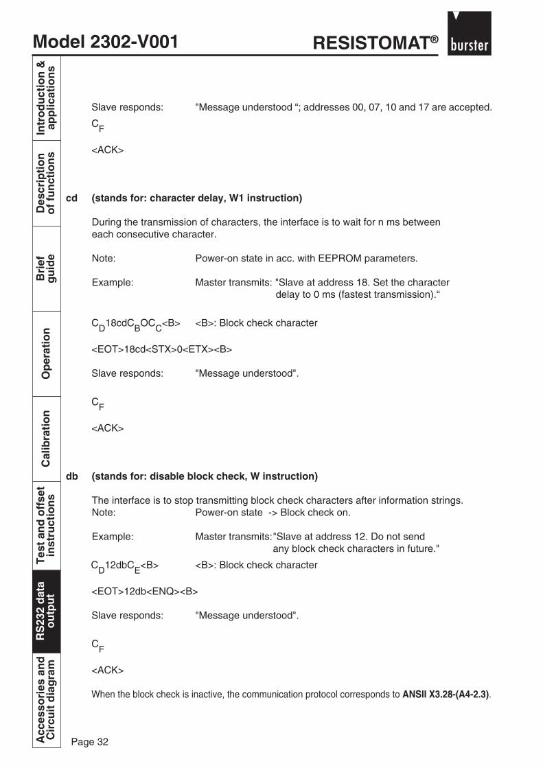
Slave responds: "Message understood “; addresses 00, 07, 10 and 17 are accepted.
CF
<ACK>
cd (stands for: character delay, W1 instruction)
During the transmission of characters, the interface is to wait for n ms betweeneach consecutive character.
Note: Power-on state in acc. with EEPROM parameters.
Example: Master transmits: "Slave at address 18. Set the character delay to 0 ms (fastest transmission).“
CD18cdCBOCC<B> <B>: Block check character
<EOT>18cd<STX>0<ETX><B>
Slave responds: "Message understood".
CF
<ACK>
db (stands for: disable block check, W instruction)
The interface is to stop transmitting block check characters after information strings.Note: Power-on state -> Block check on.
Example: Master transmits:"Slave at address 12. Do not sendany block check characters in future."
CD12dbCE<B> <B>: Block check character
<EOT>12db<ENQ><B>
Slave responds: "Message understood".
CF
<ACK>
When the block check is inactive, the communication protocol corresponds to ANSII X3.28-(A4-2.3).

Model 2302-V001RESISTOMAT®
Page 33
Bri
efg
uid
eO
per
atio
nC
alib
rati
on
Tes
t an
d o
ffse
tin
stru
ctio
ns
RS
232
dat
ao
utp
ut
Intr
od
uct
ion
&ap
plic
atio
ns
Des
crip
tio
no
f fu
nct
ion
sA
cces
sori
es a
nd
Cir
cuit
dia
gra
mR
S23
2 d
ata
ou
tpu
t
eb (stands for: enable block check, W instruction)
The interface is to include a block check character in string transmissions.This character is appended to every information telegram after the last controlcharacter.
Note: Power-on state -> block check on.
Example: Master transmits:"Slave at address 00. Include a block check character in future transmissions.“
CD00ebCE
<EOT>00eb<ENQ>
Slave responds: "Message understood"
CF
<ACK>
er (stands for: send error status, R instruction)
The device with the transferred ID is to send the number of the error which occurred last.
Example: Master transmits: "Slave at address 00. Send error status"
CD00erCE
<EOT>00er<ENQ>
Slave responds: "No error (error code 00)"
CB00CC<Block check>
<STX>00<ETX><Block check>
Master transmits: "Message understood"
CF
<ACK>
RESISTOMAT®Model 2302-V001
Page 34
Intr
od
uct
ion
&ap
plic
atio
ns
Des
crip
tio
no
f fu
nct
ion
sB
rief
gu
ide
Op
erat
ion
Cal
ibra
tio
nT
est
and
off
set
inst
ruct
ion
sR
S23
2 d
ata
ou
tpu
tA
cces
sori
es a
nd
Cir
cuit
dia
gra
mR
S23
2 d
ata
ou
tpu
t
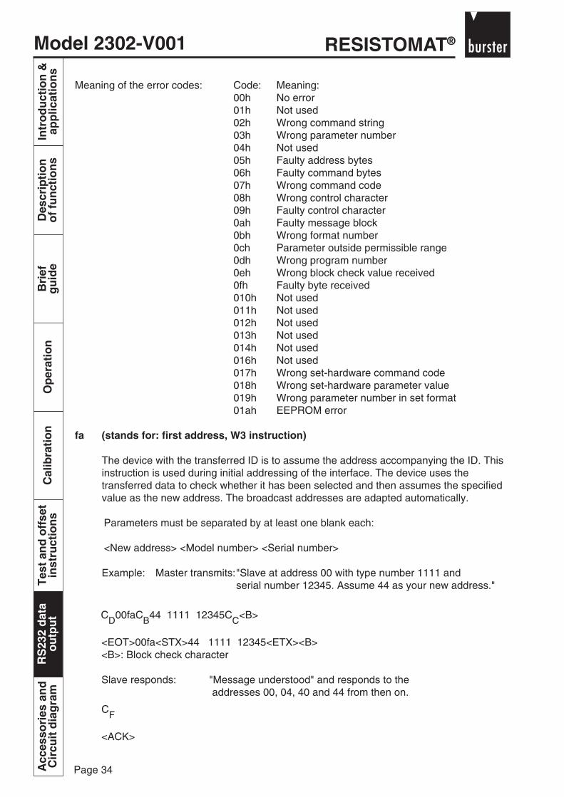
Meaning of the error codes: Code: Meaning:00h No error01h Not used02h Wrong command string03h Wrong parameter number04h Not used05h Faulty address bytes06h Faulty command bytes07h Wrong command code08h Wrong control character09h Faulty control character0ah Faulty message block0bh Wrong format number0ch Parameter outside permissible range0dh Wrong program number0eh Wrong block check value received0fh Faulty byte received010h Not used011h Not used012h Not used013h Not used014h Not used016h Not used017h Wrong set-hardware command code018h Wrong set-hardware parameter value019h Wrong parameter number in set format01ah EEPROM error
fa (stands for: first address, W3 instruction)
The device with the transferred ID is to assume the address accompanying the ID. Thisinstruction is used during initial addressing of the interface. The device uses thetransferred data to check whether it has been selected and then assumes the specifiedvalue as the new address. The broadcast addresses are adapted automatically.
Parameters must be separated by at least one blank each:
<New address> <Model number> <Serial number>
Example: Master transmits:"Slave at address 00 with type number 1111 andserial number 12345. Assume 44 as your new address."
CD00faCB44 1111 12345CC<B>
<EOT>00fa<STX>44 1111 12345<ETX><B><B>: Block check character
Slave responds: "Message understood" and responds to the addresses 00, 04, 40 and 44 from then on.
CF
<ACK>

Model 2302-V001RESISTOMAT®
Page 35
Bri
efg
uid
eO
per
atio
nC
alib
rati
on
Tes
t an
d o
ffse
tin
stru
ctio
ns
RS
232
dat
ao
utp
ut
Intr
od
uct
ion
&ap
plic
atio
ns
Des
crip
tio
no
f fu
nct
ion
sA
cces
sori
es a
nd
Cir
cuit
dia
gra
mR
S23
2 d
ata
ou
tpu
t
id (stands for: identification, R3 instruction)
The addressed device is to transmit its type description to the controller (Master).The type description contains the type number, software version and serial number,each separated by a blank.
Example: Master transmits:"Slave at address 11. Send your identification."
CD11idC<ENQ>
Slave responds: "Message understood. Type number 1234, software version 2.11, serial number 65111"
CF
<ACK>
na (stands for: new address, W1 instruction)
This instruction allows the interface to be set to a new address. The instruction is sentto the current address. It is thus not suitable for specifying the address immediately aftersystem start. The device with the transferred ID is to assume the new address accompanyingthe ID.
Parameter: <New address>
Example: Master transmits: "Slave at address 25. Change your address to 13."
CD25naCB13CC<Block check character>
<EOT>25na<STX>13<ETX>
Slave responds: "Message understood" and responds to the addresses 00, 03, 10 and 13 from then on.
CF
<ACK>
nb (stands for: no broadcast, W instruction)
The interface is to respond only to its individual address, i.e. the broadcastingcapability is inhibited.
Example: Master transmits:"Slave at address 17. Deactivateyour broadcast addresses."
CD17bcCE
<EOT>17bc<ENQ>
Slave responds: "Message understood". Only address 17 is accepted from now on.
CF
<ACK>
RESISTOMAT®Model 2302-V001
Page 36
Intr
od
uct
ion
&ap
plic
atio
ns
Des
crip
tio
no
f fu
nct
ion
sB
rief
gu
ide
Op
erat
ion
Cal
ibra
tio
nT
est
and
off
set
inst
ruct
ion
sR
S23
2 d
ata
ou
tpu
tA
cces
sori
es a
nd
Cir
cuit
dia
gra
mR
S23
2 d
ata
ou
tpu
t
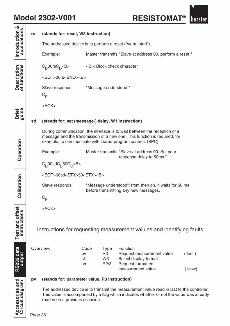
rs (stands for: reset, W3 instruction)
The addressed device is to perform a reset ("warm start").
Example: Master transmits:"Slave at address 00, perform a reset."
CD00rsCD<B> <B>: Block check character
<EOT>00rs<ENQ><B>
Slave responds: "Message understood."
CF
<ACK>
sd (stands for: set (message-) delay, W1 instruction)
During communication, the interface is to wait between the reception of amessage and the transmission of a new one. This function is required, forexample, to communicate with stored-program controls (SPC).
Example: Master transmits:"Slave at address 00. Set yourresponse delay to 50ms."
CD00sdCB50CC<B>
<EOT>00sd<STX>50<ETX><B>
Slave responds: "Message understood"; from then on, it waits for 50 msbefore transmitting any new messages.
CF
<ACK>
Instructions for requesting measurement valules and identifying faults
Overview: Code Type Functionpv R3 Request measurement value ( fast )sf W3 Select display formatsm R2/3 Request formatted
measurement value ( slow)
pv (stands for: parameter value, R3 instruction)
The addressed device is to transmit the measurement value read in last to the controller.This value is accompanied by a flag which indicates whether or not the value was alreadyread in on a previous occasion.
Model 2302-V001RESISTOMAT®
Page 37
Bri
efg
uid
eO
per
atio
nC
alib
rati
on
Tes
t an
d o
ffse
tin
stru
ctio
ns
RS
232
dat
ao
utp
ut
Intr
od
uct
ion
&ap
plic
atio
ns
Des
crip
tio
no
f fu
nct
ion
sA
cces
sori
es a
nd
Cir
cuit
dia
gra
mR
S23
2 d
ata
ou
tpu
t
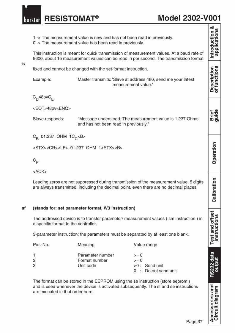
1 -> The measurement value is new and has not been read in previously.0 -> The measurement value has been read in previously.
This instruction is meant for quick transmission of measurement values. At a baud rate of9600, about 15 measurement values can be read in per second. The transmission format
isfixed and cannot be changed with the set-format instruction.
Example: Master transmits:"Slave at address 480, send me your latest measurement value."
CD48pvCE
<EOT>48pv<ENQ>
Slave responds: "Message understood. The measurement value is 1.237 Ohmsand has not been read in previously."
CB 01.237 OHM 1CC<B>
<STX><CR><LF> 01.237 OHM 1<ETX><B>
CF
<ACK>
Leading zeros are not suppressed during transmission of the measurement value. 5 digitsare always transmitted, including the decimal point, even there are no decimal places.
sf (stands for: set parameter format, W3 instruction)
The addressed device is to transfer parameter/ measurement values ( sm instruction ) ina specific format to the controller.
3-parameter instruction; the parameters must be separated by at least one blank.
Par.-No. Meaning Value range
1 Parameter number >= 02 Format number >= 03 Unit code >0 : Send unit
0 : Do not send unit
The format can be stored in the EEPROM using the se instruction (store eeprom )and is used whenever the device is activated subsequently. The sf and se instructionsare executed in that order here.

RESISTOMAT®Model 2302-V001
Page 38
Intr
od
uct
ion
&ap
plic
atio
ns
Des
crip
tio
no
f fu
nct
ion
sB
rief
gu
ide
Op
erat
ion
Cal
ibra
tio
nT
est
and
off
set
inst
ruct
ion
sR
S23
2 d
ata
ou
tpu
tA
cces
sori
es a
nd
Cir
cuit
dia
gra
mR
S23
2 d
ata
ou
tpu
t
The following display types are assigned to the format numbers:No. C-format Display
0: %9.0f ±********* 1: %9.1f ±*******.* 2: %9.2f ±******.** 3: %9.3f ±*****.*** 4: %9.4f ±****.**** 5: %9.5f ±***.***** 6: %9.6f ±**.****** 7: %9.7f ±*.******* 8: %9.8f ±.******E±** 9: %f Floating point
Example: Master transmits:"Slave at address 17. For the future communication of measurement values, select Format 3 plus unit transmission."
CD17sfCB0 3 1CC<B> <B>:Block check character
<EOT>00sd<STX>50<ETX><B>
Slave responds: "Message understood."
CF
<ACK>
sm (stands for: send measurement value, R2/3 instruction)The addressed device is to transmit the measurement value read in last to the controller.This value is accompanied by a flag which indicates whether or not the value was alreadyread in on a previous occasion.1 -> The measurement value is new and has not been read in previously.0 -> The measurement value has been read in previously.
The transmission format can be specified with the set-format instruction. However, thisinstruction is considerably slower than the pv instruction.
Example: Master transmits:"Slave at address 48. Set your response delay to 50ms!"
CD48smCE
<EOT>48sm<ENQ>
Slave responds: "Message understood. The measurement value is 1.237 Ohmsand has not been read in previously."
CB 01.237 Ohm 1CC<B>
<STX><CR><LF> 01.237 Ohm 1<ETX><B>
Master antwortet: "Message understood."
CF
<ACK>

Model 2302-V001RESISTOMAT®
Page 39
Bri
efg
uid
eO
per
atio
nC
alib
rati
on
Tes
t an
d o
ffse
tin
stru
ctio
ns
RS
232
dat
ao
utp
ut
Intr
od
uct
ion
&ap
plic
atio
ns
Des
crip
tio
no
f fu
nct
ion
sA
cces
sori
es a
nd
Cir
cuit
dia
gra
mR
S23
2 d
ata
ou
tpu
t
Instructions for device control
Description of programmable parameters:
Some characteristics of the interface module are specified using programmable parameters.These can be changed with the parameter write instruction (pw) and read out with the parameterread instruction (pr). If the parameters are to be used on a long-term basis, they must be storedin the EEPROM with the store EPROM instruction (se) which allows them to be used even afterthe module is restarted.
Parameter 0: Parameter of the measurement value.
Parameter 1: Number of lines per page for printer operation.( Default setting: 60 )
Parameter 2: Character delay in msec.( Default setting: 0 )
Parameter 3: Send delay in msec.( Default setting: 0 )
Parameter 4: ASCII character for <FF> ( formfeed ) ( printer operation )( Default setting: 12 )
Parameter 5: ASCII character for <CR> ( carriage return ) ( printer operation)( Default setting: 13 )
Parameter 6: ASCII character for <LF> ( linefeed ) ( printer operation )( Default setting: 10 )
Parameter 7: Not used.
Parameter 8: Print format:The printout format is specified with this parameter. The syntax forspecifying the format is identical to that of the programming language C( printf function ) and must be observed precisely. If this parameteris not defined, the print output either fails or is faulty.This parameter must not exceed 70 characters.Example: „ %d,\t%9.3f,\t%s\n“,no,measvalue,unitThe format specified above effects a printout of the serial number withdecimal places, a tabulator and the measurement unit, followed by a linefeed.
The following values can be output:
Name of the output value: Type: Format:
no integer %dmeasurement value float %funit string %s
Escape sequences other than \n ( new line )and \t (tabulator) are not permissible.
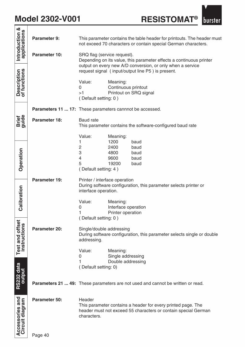
RESISTOMAT®Model 2302-V001
Page 40
Intr
od
uct
ion
&ap
plic
atio
ns
Des
crip
tio
no
f fu
nct
ion
sB
rief
gu
ide
Op
erat
ion
Cal
ibra
tio
nT
est
and
off
set
inst
ruct
ion
sR
S23
2 d
ata
ou
tpu
tA
cces
sori
es a
nd
Cir
cuit
dia
gra
mR
S23
2 d
ata
ou
tpu
t
Parameter 9: This parameter contains the table header for printouts. The header mustnot exceed 70 characters or contain special German characters.
Parameter 10: SRQ flag (service request).Depending on its value, this parameter effects a continuous printeroutput on every new A/D conversion, or only when a servicerequest signal ( input/output line P5 ) is present.
Value: Meaning:0 Continuous printout>1 Printout on SRQ signal( Default setting: 0 )
Parameters 11 ... 17: These parameters cannnot be accessed.
Parameter 18: Baud rateThis parameter contains the software-configured baud rate
Value: Meaning:1 1200 baud2 2400 baud3 4800 baud4 9600 baud5 19200 baud( Default setting: 4 )
Parameter 19: Printer / interface operationDuring software configuration, this parameter selects printer orinterface operation.
Value: Meaning:0 Interface operation1 Printer operation( Default setting: 0 )
Parameter 20: Single/double addressingDuring software configuration, this parameter selects single or doubleaddressing.
Value: Meaning:0 Single addressing1 Double addressing( Default setting: 0)
Parameters 21 ... 49: These parameters are not used and cannot be written or read.
Parameter 50: HeaderThis parameter contains a header for every printed page. Theheader must not exceed 55 characters or contain special Germancharacters.

Model 2302-V001RESISTOMAT®
Page 41
Bri
efg
uid
eO
per
atio
nC
alib
rati
on
Tes
t an
d o
ffse
tin
stru
ctio
ns
RS
232
dat
ao
utp
ut
Intr
od
uct
ion
&ap
plic
atio
ns
Des
crip
tio
no
f fu
nct
ion
sA
cces
sori
es a
nd
Cir
cuit
dia
gra
mR
S23
2 d
ata
ou
tpu
t
pr (stands for: parameter read, W1/R instruction)
The value of the requested parameter is to be transferred from the addressed device.
Par.-No. Meaning Value range1 Parameter number >=0
Example: Master transmits:"Slave at address 00. Send me the current value of parameter 33!"
CD00prCB33CC<B> <B>: Block check character
<EOT>00pr<STX>33<ETX><B>
Slave responds: "Message understood. The value of parameter 33 is 3.147"
CB33 3.147CC<B> <B>: Block check character
<STX>33 3.147<ETX><B>
Master responds: "Message understood"
CF
<ACK>
pw (stands for: parameter write, W2R instruction)Program parameters are to be changed by the addressed device.
2-parameter instructionPar.-No. Meaning Value range1 Parameter number >=02 Setting Integer, floating-point number or
string in the case of stringparameters (8, 9, 50).
Example: Master transmits: "Slave at address 00. Set parameter 3 to 1.005."
CD00pwCB3 1.005CC<B> <B>: Block check character
<EOT>00pw<STX>3 1.005<ETX><B>
Slave responds: "Message understood."
CF
<ACK>
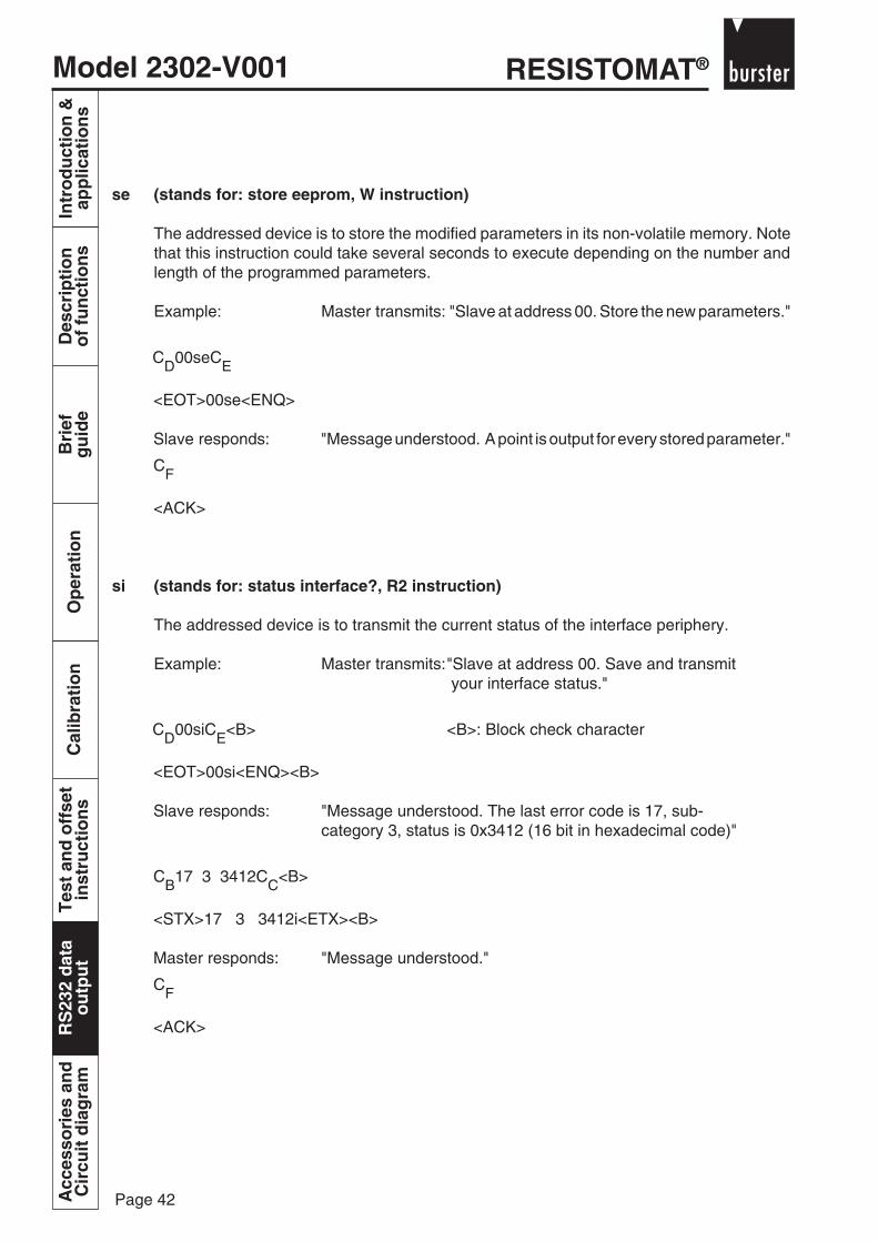
RESISTOMAT®Model 2302-V001
Page 42
Intr
od
uct
ion
&ap
plic
atio
ns
Des
crip
tio
no
f fu
nct
ion
sB
rief
gu
ide
Op
erat
ion
Cal
ibra
tio
nT
est
and
off
set
inst
ruct
ion
sR
S23
2 d
ata
ou
tpu
tA
cces
sori
es a
nd
Cir
cuit
dia
gra
mR
S23
2 d
ata
ou
tpu
t
se (stands for: store eeprom, W instruction)
The addressed device is to store the modified parameters in its non-volatile memory. Notethat this instruction could take several seconds to execute depending on the number andlength of the programmed parameters.
Example: Master transmits: "Slave at address 00. Store the new parameters."
CD00seCE
<EOT>00se<ENQ>
Slave responds: "Message understood. A point is output for every stored parameter."
CF
<ACK>
si (stands for: status interface?, R2 instruction)
The addressed device is to transmit the current status of the interface periphery.
Example: Master transmits:"Slave at address 00. Save and transmit your interface status."
CD00siCE<B> <B>: Block check character
<EOT>00si<ENQ><B>
Slave responds: "Message understood. The last error code is 17, sub-category 3, status is 0x3412 (16 bit in hexadecimal code)"
CB17 3 3412CC<B>
<STX>17 3 3412i<ETX><B>
Master responds: "Message understood."
CF
<ACK>
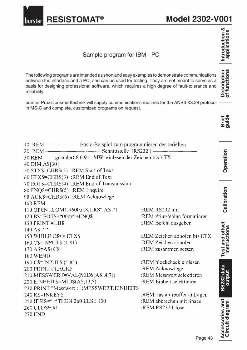
Model 2302-V001RESISTOMAT®
Page 43
Bri
efg
uid
eO
per
atio
nC
alib
rati
on
Tes
t an
d o
ffse
tin
stru
ctio
ns
RS
232
dat
ao
utp
ut
Intr
od
uct
ion
&ap
plic
atio
ns
Des
crip
tio
no
f fu
nct
ion
sA
cces
sori
es a
nd
Cir
cuit
dia
gra
mR
S23
2 d
ata
ou
tpu
t
Sample program for IBM - PC
The following programs are intended as short and easy examples to demonstrate communicationsbetween the interface and a PC, and can be used for testing. They are not meant to serve as abasis for designing professional software, which requires a high degree of fault-tolerance andreliability.
burster Präzisionsmeßtechnik will supply communications routines for the ANSII X3.28 protocolin MS-C and complete, customized programs on request.

RESISTOMAT®Model 2302-V001
Page 44
Intr
od
uct
ion
&ap
plic
atio
ns
Des
crip
tio
no
f fu
nct
ion
sB
rief
gu
ide
Op
erat
ion
Cal
ibra
tio
nT
est
and
off
set
inst
ruct
ion
sR
S23
2 d
ata
ou
tpu
tA
cces
sori
es a
nd
Cir
cuit
dia
gra
m

Model 2302-V001RESISTOMAT®
Page 45
Bri
efg
uid
eO
per
atio
nC
alib
rati
on
Tes
t an
d o
ffse
tin
stru
ctio
ns
RS
232
dat
ao
utp
ut
Intr
od
uct
ion
&ap
plic
atio
ns
Des
crip
tio
no
f fu
nct
ion
sA
cces
sori
es a
nd
Cir
cuit
dia
gra
m
Circuit diagram and AccessoriesCircuit digram
Picture 6: Circuit diagram - Current source
Cur
rent
sou
rce
Acc
esso
ries
an
dC
ircu
it d
iag
ram

RESISTOMAT®Model 2302-V001
Page 46
Intr
od
uct
ion
&ap
plic
atio
ns
Des
crip
tio
no
f fu
nct
ion
sB
rief
gu
ide
Op
erat
ion
Cal
ibra
tio
nT
est
and
off
set
inst
ruct
ion
sR
S23
2 d
ata
ou
tpu
tA
cces
sori
es a
nd
Cir
cuit
dia
gra
m
Vol
tage
am
plifi
er
Picture 7: Circuit diagram - Voltage amplifier
Acc
esso
ries
an
dC
ircu
it d
iag
ram
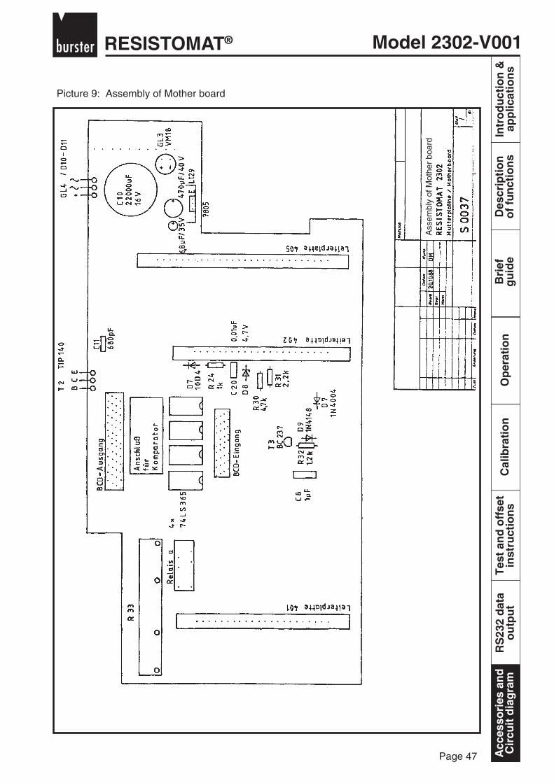
Model 2302-V001RESISTOMAT®
Page 47
Bri
efg
uid
eO
per
atio
nC
alib
rati
on
Tes
t an
d o
ffse
tin
stru
ctio
ns
RS
232
dat
ao
utp
ut
Intr
od
uct
ion
&ap
plic
atio
ns
Des
crip
tio
no
f fu
nct
ion
sA
cces
sori
es a
nd
Cir
cuit
dia
gra
m
Picture 9: Assembly of Mother board
Ass
embl
y of
Mot
her
boar
d
Acc
esso
ries
an
dC
ircu
it d
iag
ram
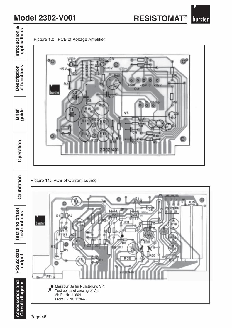
RESISTOMAT®Model 2302-V001
Page 48
Intr
od
uct
ion
&ap
plic
atio
ns
Des
crip
tio
no
f fu
nct
ion
sB
rief
gu
ide
Op
erat
ion
Cal
ibra
tio
nT
est
and
off
set
inst
ruct
ion
sR
S23
2 d
ata
ou
tpu
tA
cces
sori
es a
nd
Cir
cuit
dia
gra
m
Picture 10: PCB of Voltage Amplifier
Picture 11: PCB of Current source
Messpunkte für Nullstellung V 4Test points of zeroing of V 4Ab F - Nr. 11864From F - Nr. 11864
Acc
esso
ries
an
dC
ircu
it d
iag
ram

Model 2302-V001RESISTOMAT®
Page 49
Bri
efg
uid
eO
per
atio
nC
alib
rati
on
Tes
t an
d o
ffse
tin
stru
ctio
ns
RS
232
dat
ao
utp
ut
Intr
od
uct
ion
&ap
plic
atio
ns
Des
crip
tio
no
f fu
nct
ion
sA
cces
sori
es a
nd
Cir
cuit
dia
gra
m
Accessories for RESISTOMAT® 2302
Model 1240
Calibration Resistor
DKD Calibration Certificateburster präzisionsmeßtechnik at Gernsbach have set up acalibration centre for electrical quantities, connected to theGerman Calibration Service (DKD). This calibration centreis supervised by the Physikalisch-Technische-Bundesan-stalt (PTB) at Braunschweig and is entitled to issuecalibration certificates. The measurement results anduncertainties contained in the calibration certificate areobtained by using standards and measurement instru-ments subject to regular comparison with state standardsof the Federal Rebuplic of Germany and are thereforeconstant with these. The proof of state control exists in theform of the calibration certificate itself and in a calibrationmark which is put on the test piece.The resistor described can be supplied with aDKD Calibration Certificate.
DKD Calibration Certificate for a calibrated resistor ofseries 1240Order code 12DKD-1240
Manufacturer Calibration Certificate
Please refer to DKD Calibration Certificate but withreduced accuracy.The traceability of the used secondary voltage andresistance standards to the national standards accordingto DIN ISO 9000ff is guaranteed by our certified calibrationlaboratory (DKD-02101)
model 12WKS-1240
ApplicationThe 0.02 class calibrated resistors excel in their moderndesign and small mechanical dimensions. Theirruggedness also ensures a long life.
Calibration resistors of the 1240 series are usedwherever very constant operating standards arerequired. Typical main areas of application therefore
include:
- when normal resistors prove to be too large- to test measuring bridges- for tests on electrical temperature measuring
equipment- for laboratory setup of a Wheatstone bridge- to setup plate circuits- for a defined current characteristic at a defined
voltage- as shunt resistor for current measurement- as part of standard equipment in research
laboratories- for a large part of measurements in calibration
workshop.
With the delivery of this calibration resistor you get a testcertificate corresponding ISO 9000 with detailedtechnical data.
Low capacitance and low inductance design
Suitable for direct current and technical frequencies
High stability < ± 0.01 % over years
current clamp
voltage tap
Acc
esso
ries
an
dC
ircu
it d
iag
ram
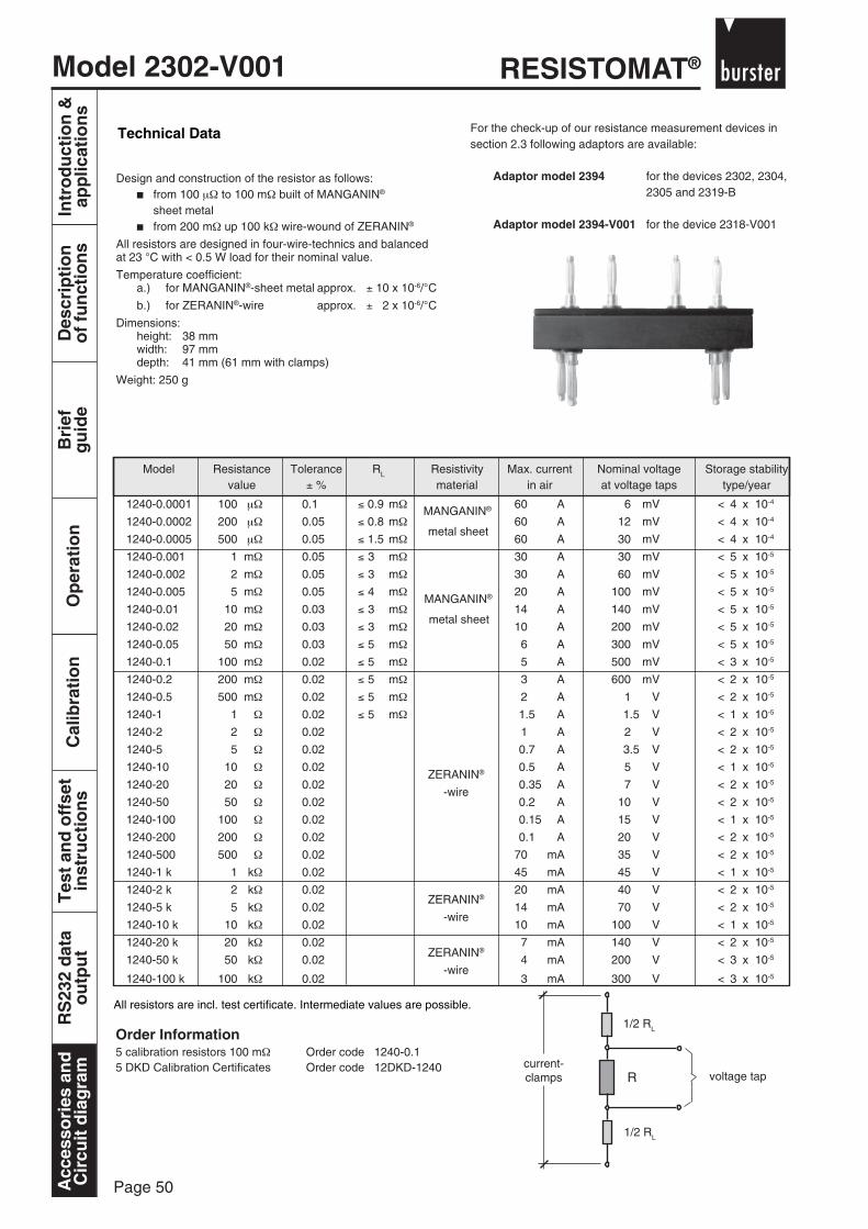
RESISTOMAT®Model 2302-V001
Page 50
Intr
od
uct
ion
&ap
plic
atio
ns
Des
crip
tio
no
f fu
nct
ion
sB
rief
gu
ide
Op
erat
ion
Cal
ibra
tio
nT
est
and
off
set
inst
ruct
ion
sR
S23
2 d
ata
ou
tpu
tA
cces
sori
es a
nd
Cir
cuit
dia
gra
m
Technical Data
ZERANIN®
-wire
ZERANIN®
-wire
ZERANIN®
-wire
Design and construction of the resistor as follows: from 100 µΩ to 100 mΩ built of MANGANIN®
sheet metal from 200 mΩ up 100 kΩ wire-wound of ZERANIN®
All resistors are designed in four-wire-technics and balancedat 23 °C with < 0.5 W load for their nominal value.
Temperature coefficient:a.) for MANGANIN®-sheet metal approx. ± 10 x 10-6/°C
b.) for ZERANIN®-wire approx. ± 2 x 10⁻⁶/°C
Dimensions:height: 38 mmwidth: 97 mmdepth: 41 mm (61 mm with clamps)
Weight: 250 g
Order Information5 calibration resistors 100 mΩ Order code 1240-0.15 DKD Calibration Certificates Order code 12DKD-1240
voltage tap
1/2 RL
R
1/2 RL
current-clamps
MANGANIN®
metal sheet
MANGANIN®
metal sheet
Model Resistance Tolerance RL Resistivity Max. current Nominal voltage Storage stabilityvalue ± % material in air at voltage taps type/year
1240-0.0001 100 µΩ 0.1 ≤ 0.9 mΩ 60 A 6 mV < 4 x 10⁻⁴
1240-0.0002 200 µΩ 0.05 ≤ 0.8 mΩ 60 A 12 mV < 4 x 10⁻⁴
1240-0.0005 500 µΩ 0.05 ≤ 1.5 mΩ 60 A 30 mV < 4 x 10⁻⁴
1240-0.001 1 mΩ 0.05 ≤ 3 mΩ 30 A 30 mV < 5 x 10⁻⁵
1240-0.002 2 mΩ 0.05 ≤ 3 mΩ 30 A 60 mV < 5 x 10⁻⁵
1240-0.005 5 mΩ 0.05 ≤ 4 mΩ 20 A 100 mV < 5 x 10⁻⁵
1240-0.01 10 mΩ 0.03 ≤ 3 mΩ 14 A 140 mV < 5 x 10⁻⁵
1240-0.02 20 mΩ 0.03 ≤ 3 mΩ 10 A 200 mV < 5 x 10⁻⁵
1240-0.05 50 mΩ 0.03 ≤ 5 mΩ 6 A 300 mV < 5 x 10⁻⁵
1240-0.1 100 mΩ 0.02 ≤ 5 mΩ 5 A 500 mV < 3 x 10⁻⁵
1240-0.2 200 mΩ 0.02 ≤ 5 mΩ 3 A 600 mV < 2 x 10⁻⁵
1240-0.5 500 mΩ 0.02 ≤ 5 mΩ 2 A 1 V < 2 x 10⁻⁵
1240-1 1 Ω 0.02 ≤ 5 mΩ 1.5 A 1.5 V < 1 x 10⁻⁵
1240-2 2 Ω 0.02 1 A 2 V < 2 x 10⁻⁵
1240-5 5 Ω 0.02 0.7 A 3.5 V < 2 x 10⁻⁵
1240-10 10 Ω 0.02 0.5 A 5 V < 1 x 10⁻⁵
1240-20 20 Ω 0.02 0.35 A 7 V < 2 x 10⁻⁵
1240-50 50 Ω 0.02 0.2 A 10 V < 2 x 10⁻⁵
1240-100 100 Ω 0.02 0.15 A 15 V < 1 x 10⁻⁵
1240-200 200 Ω 0.02 0.1 A 20 V < 2 x 10⁻⁵
1240-500 500 Ω 0.02 70 mA 35 V < 2 x 10⁻⁵
1240-1 k 1 kΩ 0.02 45 mA 45 V < 1 x 10⁻⁵
1240-2 k 2 kΩ 0.02 20 mA 40 V < 2 x 10⁻⁵
1240-5 k 5 kΩ 0.02 14 mA 70 V < 2 x 10⁻⁵
1240-10 k 10 kΩ 0.02 10 mA 100 V < 1 x 10⁻⁵
1240-20 k 20 kΩ 0.02 7 mA 140 V < 2 x 10⁻⁵
1240-50 k 50 kΩ 0.02 4 mA 200 V < 3 x 10⁻⁵
1240-100 k 100 kΩ 0.02 3 mA 300 V < 3 x 10⁻⁵
For the check-up of our resistance measurement devices insection 2.3 following adaptors are available:
Adaptor model 2394 for the devices 2302, 2304,2305 and 2319-B
Adaptor model 2394-V001 for the device 2318-V001
All resistors are incl. test certificate. Intermediate values are possible.
Acc
esso
ries
an
dC
ircu
it d
iag
ram
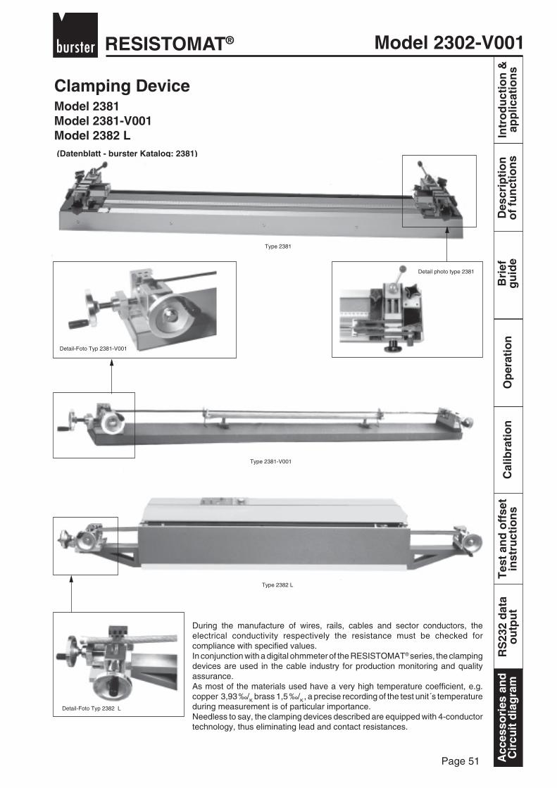
Model 2302-V001RESISTOMAT®
Page 51
Bri
efg
uid
eO
per
atio
nC
alib
rati
on
Tes
t an
d o
ffse
tin
stru
ctio
ns
RS
232
dat
ao
utp
ut
Intr
od
uct
ion
&ap
plic
atio
ns
Des
crip
tio
no
f fu
nct
ion
sA
cces
sori
es a
nd
Cir
cuit
dia
gra
m
Clamping Device
(Datenblatt - burster Katalog: 2381)
Model 2381Model 2381-V001Model 2382 L
Detail-Foto Typ 2381-V001
Detail-Foto Typ 2382 L
Type 2382 L
Type 2381-V001
Type 2381
During the manufacture of wires, rails, cables and sector conductors, theelectrical conductivity respectively the resistance must be checked forcompliance with specified values.In conjunction with a digital ohmmeter of the RESISTOMAT® series, the clampingdevices are used in the cable industry for production monitoring and qualityassurance.As most of the materials used have a very high temperature coefficient, e.g.copper 3,93 ‰/K brass 1,5 ‰/K , a precise recording of the test unit´s temperatureduring measurement is of particular importance.Needless to say, the clamping devices described are equipped with 4-conductortechnology, thus eliminating lead and contact resistances.
Detail photo type 2381
Acc
esso
ries
an
dC
ircu
it d
iag
ram
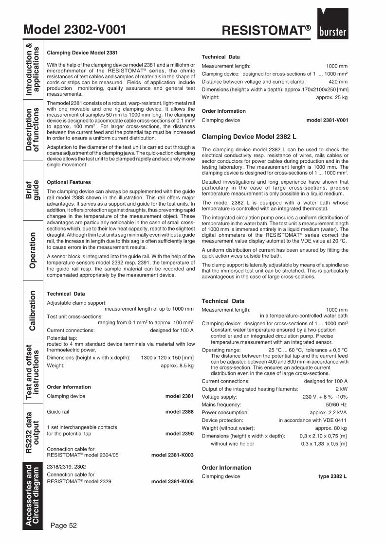
RESISTOMAT®Model 2302-V001
Page 52
Intr
od
uct
ion
&ap
plic
atio
ns
Des
crip
tio
no
f fu
nct
ion
sB
rief
gu
ide
Op
erat
ion
Cal
ibra
tio
nT
est
and
off
set
inst
ruct
ion
sR
S23
2 d
ata
ou
tpu
tA
cces
sori
es a
nd
Cir
cuit
dia
gra
m
Clamping Device Model 2381
With the help of the clamping device model 2381 and a milliohm ormicroohmmeter of the RESISTOMAT® series, the ohmicresistances of test cables and samples of materials in the shape ofcords or strips can be measured. Fields of application includeproduction monitoring, quality assurance and general testmeasurements.
Themodel 2381 consists of a robust, warp-resistant, light-metal railwith one movable and one rig clamping device. It allows themeasurement of samples 50 mm to 1000 mm long. The clampingdevice is designed to accomodate cable cross-sections of 0.1 mm2
to approx. 100 mm2 . For larger cross-sections, the distancesbetween the current feed and the potential tap must be increasedin order to ensure a uniform current distribution.
Adaptation to the diameter of the test unit is carried out through acoarse adjustment of the clamping jaws. The quick-action clampingdevice allows the test unit to be clamped rapidly and securely in onesingle movement.
Optional Features
The clamping device can always be supplemented with the guiderail model 2388 shown in the illustration. This rail offers majoradvantages. It serves as a support and guide for the test units. Inaddition, it offers protection against draughts, thus preventing rapidchanges in the temperature of the measurement object. Theseadvantages are particularly noticeable in the case of small cross-sections which, due to their low heat capacity, react to the slightestdraught. Although thin test units sag minimally even without a guiderail, the increase in length due to this sag is often sufficiently largeto cause errors in the measurement results.
A sensor block is integrated into the guide rail. With the help of thetemperature sensors model 2392 resp. 2391, the temperature ofthe guide rail resp. the sample material can be recorded andcompensated appropriately by the measurement device.
Technical Data
Adjustable clamp support:measurement length of up to 1000 mm
Test unit cross-sections:ranging from 0.1 mm2 to approx. 100 mm2
Current connections: designed for 100 A
Potential tap:routed to 4 mm standard device terminals via material with lowthermoelectric power.
Dimensions (height x width x depth): 1300 x 120 x 150 [mm]
Weight: approx. 8.5 kg
Order Information
Clamping device model 2381
Guide rail model 2388
1 set interchangeable contactsfor the potential tap model 2390
Connection cable forRESISTOMAT® model 2304/05 model 2381-K003
2318/2319, 2302
Connection cable forRESISTOMAT® model 2329 model 2381-K006
Technical Data
Measurement length: 1000 mm
Clamping device: designed for cross-sections of 1 ... 1000 mm2
Distance between voltage and current-clamp: 420 mm
Dimensions (height x width x depth): approx.170x2100x250 [mm]
Weight: approx. 25 kg
Order Information
Clamping device model 2381-V001
Clamping Device Model 2382 L
The clamping device model 2382 L can be used to check theelectrical conductivity resp. resistance of wires, rails cables orsector conductors for power cables during production and in thetesting laboratory. The measurement length is 1000 mm. Theclamping device is designed for cross-sections of 1 ... 1000 mm2.
Detailed investigations and long experience have shown thatparticulary in the case of large cross-sections, precisetemperature measurement is only possible in a liquid medium.
The model 2382 L is equipped with a water bath whosetemperature is controlled with an integrated thermostat.
The integrated circulation pump ensures a uniform distribution oftemperature in the water bath. The test unit´s measurement lengthof 1000 mm is immersed entirely in a liquid medium (water). Thedigital ohmmeters of the RESISTOMAT® series correct themeasurement value display automat to the VDE value at 20 °C.
A uniform distribution of current has been ensured by fitting thequick action vices outside the bath.
The clamp support is laterally adjustable by means of a spindle sothat the immersed test unit can be stretched. This is particularlyadvantageous in the case of large cross-sections.
Technical DataMeasurement length: 1000 mm
in a temperature-controlled water bath
Clamping device: designed for cross-sections of 1 ... 1000 mm2
Constant water temperature ensured by a two-positioncontroller and an integrated circulation pump. Precisetemperature measurement with an integrated sensor.
Operating range: 25 °C ... 60 °C, tolerance ± 0,5 °CThe distance between the potential tap and the current feedcan be adjusted between 400 and 800 mm in accordance withthe cross-section. This ensures an adequate currentdistribution even in the case of large cross-sections.
Current connections: designed for 100 A
Output of the integrated heating filaments: 2 kW
Voltage supply: 230 V, + 6 % -10%
Mains frequency: 50/60 Hz
Power consumption: approx. 2,2 kVA
Device protection: in accordance with VDE 0411
Weight (without water): approx. 80 kg
Dimensions (height x width x depth): 0,3 x 2,10 x 0,75 [m]
without wire holder 0,3 x 1,33 x 0,5 [m]
Order InformationClamping device type 2382 L
Acc
esso
ries
an
dC
ircu
it d
iag
ram
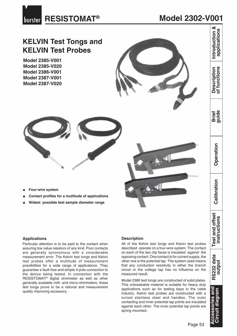
Model 2302-V001RESISTOMAT®
Page 53
Bri
efg
uid
eO
per
atio
nC
alib
rati
on
Tes
t an
d o
ffse
tin
stru
ctio
ns
RS
232
dat
ao
utp
ut
Intr
od
uct
ion
&ap
plic
atio
ns
Des
crip
tio
no
f fu
nct
ion
sA
cces
sori
es a
nd
Cir
cuit
dia
gra
m
DescriptionAll of the Kelvin test tongs and Kelvin test probesdescribed operate on a four-wire system. The contacton each of the two clip faces is insulated against theopposing contact. One contact is for current supply, theother one is the potential tap. The system used meansthat any conduction resistivity in either the branchcircuit or the voltage tap has no influence on themeasured result.
Model 2386 test tongs are constructed of solid plates.This unbreakable material is suitable for heavy dutyapplications such as for testing bays in the cableindustry. Kelvin test probes are constructed with aturned stainless steel and handles. The outercontacting and inner potential tap points are insulatedagainst each other. The inner potential tap points arespring mounted.
ApplicationsParticular attention is to be paid to the contact whenassuring low value resistors of any kind. Poor contactsare generally synonymous with a considerablemeasurement error. The Kelvin test tongs and Kelvintest probes offer a multitude of measurementpossibilities for a wide range of applications. Theyguarantee a fault-free and simple 4-pole connection tothe device being tested. In connection with theRESISTOMAT® digital ohmmeter as well as othergenerally available milli- and micro-ohmmeters, thesetest tongs prove to be a rational and measurementquality improving accessory.
KELVIN Test Tongs andKELVIN Test ProbesModel 2385-V001Model 2385-V020Model 2386-V001Model 2387-V001Model 2387-V020
Four-wire system
Contact profiles for a multitude of applications
Widest possible test sample diameter range
Acc
esso
ries
an
dC
ircu
it d
iag
ram

RESISTOMAT®Model 2302-V001
Page 54
Intr
od
uct
ion
&ap
plic
atio
ns
Des
crip
tio
no
f fu
nct
ion
sB
rief
gu
ide
Op
erat
ion
Cal
ibra
tio
nT
est
and
off
set
inst
ruct
ion
sR
S23
2 d
ata
ou
tpu
tA
cces
sori
es a
nd
Cir
cuit
dia
gra
m
30 mm
l
A = 20 mm, B = 11 mm, l = 255 mm
BA
Which KELVIN connecting cable fits which RESISTOMAT® ?Check the following table:
Model 2302 / 2304 / 2305 23292318 / 2319 / 2323
2385-V001 2385-V0202386-V001
Probe 2387-V001 2387-V020Order InformationKelvin test tongs model 2385-V001Kelvin test tongs model 2385-V020Kelvin test tongs model 2386-V001Kelvin test probe model 2387-V001Kelvin test probe model 2387-V020
Tongs
Kelvin Test Tongs ;odel 2386-V001These test tongs are used for the measurement of ohmicresistances in test bays of cable drums ready for dispatch aswell as various test samples in production plants or testlaboratories.When using different profiles in the contacting unit it ispossible to make contact on test sample cross-sectionsfrom 1 to 1000 mm2. The opening angle of the tongs and theform of the contacting profiles also permit special applicationssuch as measurement on heavy duty transformers. Thefitted supply leads are 10 m long with banana plugs.
Designs
Kelvin Test Tongs Model 2385-V001These test tongs are ideal for resistance tests on small components andare gold-plated which helps to retain lower contact resistance. Thesupply leads are 3 m long and fitted with banana plugs at the end.
Kelvin Test Tongs Model 2385-V020As model 2385-V001, however fitted with a 5-pin connector (suitable forRESISTOMAT® model 2329) 3 m length.
95 mm
Kelvin Test Probe Model 2387-V001These were specially designed for contacting low-impedancetest samples where contacting with test tongs is not possible(countersunk terminal lugs on electro motors, conductivitymeasurements on printed conductors, for example). Thepoints are made of hardened steel, guaranteeing a longservice life. The supply leads are 3 m long and fitted withbanana plugs at the end.
Kelvin Test Probe Model 2387-V020As type 2387-V001, however fittedwith a 5-pin connector(suitable for RESISTOMAT® model 2329).
Acc
esso
ries
an
dC
ircu
it d
iag
ram