resistive soldering of line n 6 ka ... - ts-msc-ci.web.cern.ch
TRANSCRIPT

LHC Project Document No.
LHC-QBQID-ES-0001-00 rev. 3.0 CERN Div./Group or Supplier/Contractor Document No.
AT-CRI-CI/TC/cl
EDMS Document No.
362427
Date: 2004-06-10
the Large Hadron Collider project
CERN CH-1211 Geneva 23 Switzerland
Installation Procedure
RESISTIVE SOLDERING OF LINE N 6 kA BUS BARS IN THE
DISPERSION SUPRESSOR ZONE
Abstract Some of the LHC Dispersion Suppressor (DS) interconnections are housing the 6 kA splices, located in line N in order to power specific quadrupole magnets. In order to respect the thermodynamic budget of the LHC machine the electrical resistance at 1.9K shall be lower than 1.5nOhms. Since 261 splices have to be carried out in the LHC machine, a reliable joining technique has to be applied. This Engineering Specification describes the technology chosen and the requirements imposed on the connections of 6 kA bus bars.
Prepared by:
Thierry Colombet AT/CRI
Checked by:
Jean-Philippe Tock
Approved by:
Alain Poncet
Approval and Distribution lists: LHC Interconnections: M. Bajko, D. Bozzini, J. Casas-Cubillos, P. Cruikshank, K. Dahlerup-Petersen, L. Evans, C. Garion, M. Genet, C. Hauviller, R. Herzog, A. Jacquemod, K. Kershaw, F. Laurent, Ph. Lebrun, P. Lepeule, E. Manola, S. Marque, S. Mathot, K-H. Mess D. Missiaen, R. Ostojic, V. Parma, A. Perin, J-L. Perinet-Marque, L. Perrollaz, A. Poncet, P. Proudlock, F. Rodriguez-Mateos, P. Rohmig, L. Rossi, E. Roy, S. Russenschuck, R. Saban, G. Schneider, N. Siegel, A. Siemko, F. Simon, B. Skoczen, P. Strubin, L. Tavian, J-Ph. Tock, D. Tommasini, Th. Tortschanoff, R. Trant, R. Veness, A. Vidal, J. Vlogaert, L. Walckiers, R. van Weelderen, W. Weingarten, L.R. Williams.
LHC Project Document No.
LHC-QBQID-ES-0001-00 rev. 3.0
Page 2 of 25
History of Changes
Rev. No. Date Pages Description of Changes
0.1 - draft
1.0
1.1
1.2
2.0
3.0
2002-10-07
2002-11-08
2002-11-08
2003-01-31
2003-02-27
2004-06-20
All
All
All
All
All
All
LHC-DC-ES-0005.00 rev. 0.1-draft: First draft prepared by Frédérique Schauf, sent for checking and approval to the above distribution list. Deadline 21 October 2002. LHC-QBQID-ES-0001.00 rev. 1.0: Change of LHC Project Number (from LHC-DC-ES-0005 to LHC-QBQID-ES-0001) + minor modifications + addition of drawings. Document released. Version 1.1: correction of a typing error. Version 1.1 released. Version 1.2-draft sent for approval to the above lists. Deadline: 17 February 2003. Minor modications included after approval circuit. Version 2.0 released. Version 2: prepared by Thierry Colombet. Major modifications.

LHC Project Document No.
LHC-QBQID-ES-0001-00 rev. 3.0
Page 3 of 25
Table of Contents
1. INTRODUCTION.......................................................................................4 2. CHOICE OF TECHNOLOGY ........................................................................4 3. RESISTIVE SOLDERING ...........................................................................5 3.1 PRINCIPLE.............................................................................................5 3.2 RESISTIVE SOLDERING OF THE 6 KA BUS BAR ...........................................5 4. DISPERSION SUPPRESSOR ZONE: ...........................................................6 4.1 DS SUBSECTOR: ....................................................................................6 4.2 CONNECTION BOX: ................................................................................7 5. PREPARATION OF THE EXTREMITIES ......................................................8 5.1 TOOLS NEEDED: ....................................................................................8 5.2 PREPARATION PROCEDURE.................................................................... 10 6. INSERTION OF THE 6 KA BUS BAR IN THE LINE N.................................14 7. RESISTIVE SOLDERING OF THE 6KA BUS BAR .......................................14 7.1 RESISTIVE SOLDERING DEVICE (PORTABLE OVEN)................................... 14 7.2 THE OVEN SYSTEM ............................................................................... 15 7.3 TOOLS NEEDED.................................................................................... 16 7.4 SOLDERING PROCEDURE....................................................................... 17 7.5 SPECIAL CASE OF SOLDERING ............................................................... 21 7.6 CONNECTION BOX WITH 12 OR 9 JUNCTIONS .......................................... 23 8. LIST OF DRAWINGS...............................................................................25 9. REFERENCE............................................................................................25
LHC Project Document No.
LHC-QBQID-ES-0001-00 rev. 3.0
Page 4 of 25
1. INTRODUCTION
Some of the LHC Dispersion Suppressor (DS) interconnections are housing the 6 kA splices, located in line N in order to power specific quadrupole magnets. In order to respect the thermodynamic budget of the LHC machine the electrical resistance at 1.9K shall be lower than 1.5nOhms. Since 261 splices have to be carried out in the LHC machine, a reliable joining technique has to be applied. This Engineering Specification describes the technology chosen and the requirements imposed on the connections of 6 kA bus bars.
2. CHOICE OF TECHNOLOGY
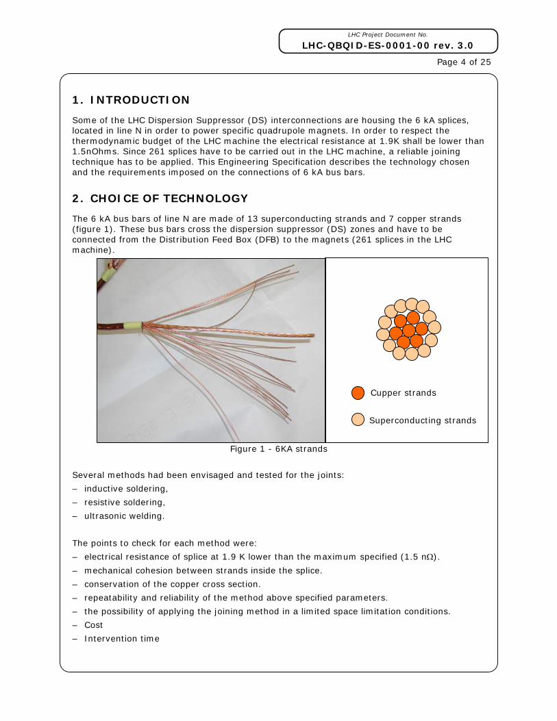
The 6 kA bus bars of line N are made of 13 superconducting strands and 7 copper strands (figure 1). These bus bars cross the dispersion suppressor (DS) zones and have to be connected from the Distribution Feed Box (DFB) to the magnets (261 splices in the LHC machine).
Figure 1 - 6KA strands
Several methods had been envisaged and tested for the joints:
– inductive soldering,
– resistive soldering,
– ultrasonic welding.
The points to check for each method were:
– electrical resistance of splice at 1.9 K lower than the maximum specified (1.5 nΩ).
– mechanical cohesion between strands inside the splice.
– conservation of the copper cross section.
– repeatability and reliability of the method above specified parameters.
– the possibility of applying the joining method in a limited space limitation conditions.
– Cost
– Intervention time
Cupper strands
Superconducting strands

LHC Project Document No.
LHC-QBQID-ES-0001-00 rev. 3.0
Page 5 of 25 The technology of ultrasonic welding turns out to be non-applicable in this case, as the high pressure needed to assure the cohesion between strands damages the superconducting strands.
The resistive soldering has been chosen, as it permits to respect the electrical and mechanical requirements, with a good repeatability and reliability. It has been estimated more applicable than inductive soldering for the simplicity of tooling, considering the relative low number of splices to carry out. Its main advantage is a compactness of the tool that allows to the work in a very confined space.
3. RESISTIVE SOLDERING
3.1 PRINCIPLE
Resistive soldering consists in heating the bus bars extremities under pressure in a specific oven with solder. Flux is also used to remove the metal oxides and to make the solder grip to the copper. Before any operation, the bus bar extremities have to be prepared as explained in chapter 5.
This process can be divided on several stages:
1. Preparation of the bus bar extremities (both sides).
2. Insertion of the 6KA bus bar into the DS zone.
3. Installation of the oven with flux, copper casing and solder layer and application of pressure.
4. Heating of the assembly.
5. Volatile evaporation, flux concentration and flux activation.
6. Solder melting.
7. Stopping of the heating.
8. Solder solidification.
9. Removal of the oven.
10. Visual check of the joints.
11. Installation of the insulation.
12. Final visual inspection.
This engineering specification will follow these stages, detailing some of them.
The soldering material used for the 6 kA bus bars splices is Sn96Ag4.
The soldering flux (Kester 135) used belongs to the class 1.1.1 of EN29454-1 (see ref [1])
3.2 RESISTIVE SOLDERING OF THE 6 KA BUS BAR
The joint has to ensure the electrical continuity between superconducting strands and between copper strands at respectively cryogenic temperature and during a quench.
Several solutions had been studied with the criteria of repeatability, reliability, electrical and mechanical resistance and facilities to execute. The chosen solution consists in preparing the cable into one flat extremity to solder. That involves preparing the extremities in two “blades” then solders these two “blades” together (see figure 2).

LHC Project Document No.
LHC-QBQID-ES-0001-00 rev. 3.0
Page 6 of 25
Figure 2 - soldering principle.
4. DISPERSION SUPPRESSOR ZONE:
The DS zone is the zone in the LHC where the beams are focused by magnetic force before the experiments. The main difference with other zone is that in order to perform this focusing, 6KA powering has to be brought to the special Short Straight Section (SSS) in addition to the usual electric cable from the Distribution Feed Box (DFB).
4.1 DS SUBSECTOR:
In the figure 3 to 5 two types of subsector are shown (from the drawing [1]) :
Figure 3 - Subsector Point 8 left
Figure 4 - Subsector Point 8 right
Cupper strands
Superconducting strands

LHC Project Document No.
LHC-QBQID-ES-0001-00 rev. 3.0
Page 7 of 25
Figure 5 - Caption
The DS zone is composed of 8 dipoles (blue), 5 SSS (green), 1 connection cryostat and DFBA (dark blue). A DS zone is almost 180m long. The reference [1], [2], [3], [4] respectively described cryomagnet, SSS, connection cryostat and DFBA.
4.2 CONNECTION BOX:
There are 8 different types of line N connection boxes in the DS zone:
_ 13 connection boxes: “600 A line N connection box (drawing [7])”
_ 10 connection boxes: “12 junctions between 6KA bus bar (drawing [8])”
_ 2 connection boxes: “9 junctions between 6KA bus bar (drawing [9])”
_ 5 connection boxes: “3 junctions between 6KA bus bar, three 6KA bus bar going through and the 600 A cable (drawing [10])”
_ 12 connection boxes: “3 junctions between 6KA bus bar, two 6KA bus bar going through and the 600 A cable (drawing [11])”
_ 12 connection boxes: “3 junctions between 6KA bus bar, one 6KA bus bar going through and the 600 A cable (drawing [12])”
_ 12 connection boxes: “3 junctions between 6KA bus bar and the 600 A cable (drawing [13])”
_ 32 connection boxes: “600 A line N connection box and the line N plug (drawing [14])”
Considering all the connection boxes, there are: (10*12+2*9+5*3+12*3+12*3+12*3)=261 junctions between 6KA bus bar.
LHC Project Document No.
LHC-QBQID-ES-0001-00 rev. 3.0
Page 8 of 25
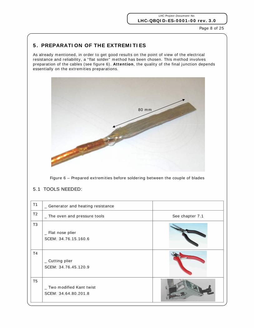
5. PREPARATION OF THE EXTREMITIES
As already mentioned, in order to get good results on the point of view of the electrical resistance and reliability, a “flat solder” method has been chosen. This method involves preparation of the cables (see figure 6). Attention, the quality of the final junction depends essentially on the extremities preparations.
Figure 6 – Prepared extremities before soldering between the couple of blades
5.1 TOOLS NEEDED:
T1 _ Generator and heating resistance
T2 _ The oven and pressure tools See chapter 7.1
T3
_ Flat nose plier
SCEM: 34.76.15.160.6
T4
_ Cutting plier
SCEM: 34.76.45.120.9
T5
_ Two modified Kant twist
SCEM: 34.64.80.201.8
80 mm

LHC Project Document No.
LHC-QBQID-ES-0001-00 rev. 3.0
Page 9 of 25
T6 _ Shears
SCEM: 34.76.95.010.9
T7
_ Scissor
SCEM: 54.21.24.004.3
T8 _ Cutter
SCEM: 34.78.54.099.6
T9 _ Metallic Brush
SCEM: 34.90.20.012.4
T10
_ Flux (Kester 135) with a brush
SCEM: 34.90.80.010.6
T11
_ Soldering station
SCEM: 34.94.56.742.4
T12 _ Protection gloves
In order to perform this preparation you will also need:
_ Solder layer Sn96Ag4 0.4*10mm in ribbon
_ Soldering Flux (Kester 135)
_ Polyimide (Kapton) tape (SCEM: 04.94.70.100.3)

LHC Project Document No.
LHC-QBQID-ES-0001-00 rev. 3.0
Page 10 of 25 5.2 PREPARATION PROCEDURE
This procedure has been defined with the help of Jean-Michel Hubert (AT/CRI/CI).
The following explanation has to be followed strictly.
1. Cut the cable 25mm longer than the final length (T6). The extremities of the cables have to be at 180 +/- 2 mm from the flange.
2. Move the steel protection by sliding it on at least 180 mm, and stick it with kapton tape or pre-preg.
3. Put the kapton tape (here in yellow) on the three cables at 90 mm from the tip. This kapton® tape will prevent the cable from stripping itself.
The process following has to be done for each cable.
4. Strip it by using the cutter (T8). There are two opposite layers of insulation.
Figure 7 - first insulation stripped
Figure 8 - Second insulation stripped 5. Identify and separate the strands
Figure 9 - Stripped cable
90 mm

LHC Project Document No.
LHC-QBQID-ES-0001-00 rev. 3.0
Page 11 of 25
Figure 10 - Identified strands
The superconducting strands are on the circumference and the copper strands around in the centre. The superconducting strands are much stiffer, less brilliant and smaller then the cupper strand.
6. Sort the strands on two groups and try to put in straight line the copper strand.
_ One with 7 superconducting strands and 3 copper strands,
_ The other with 6 superconducting strands and 4 copper strands.
7. By hand, place the strands of the first group as shown on the figure :
Figure 11 - first group of strand position.
8. Using the flat nose plier (T3) pre-place the strands inside it and then use the two modified Kant twist (5) in order to tight them. Push these kant twist at almost 20 mm from each other.
Figure 12 – Kant twist positioning
Copper strands
Superconducting strands
Copper strand Superconducting strand
LHC Project Document No.
LHC-QBQID-ES-0001-00 rev. 3.0
Page 12 of 25
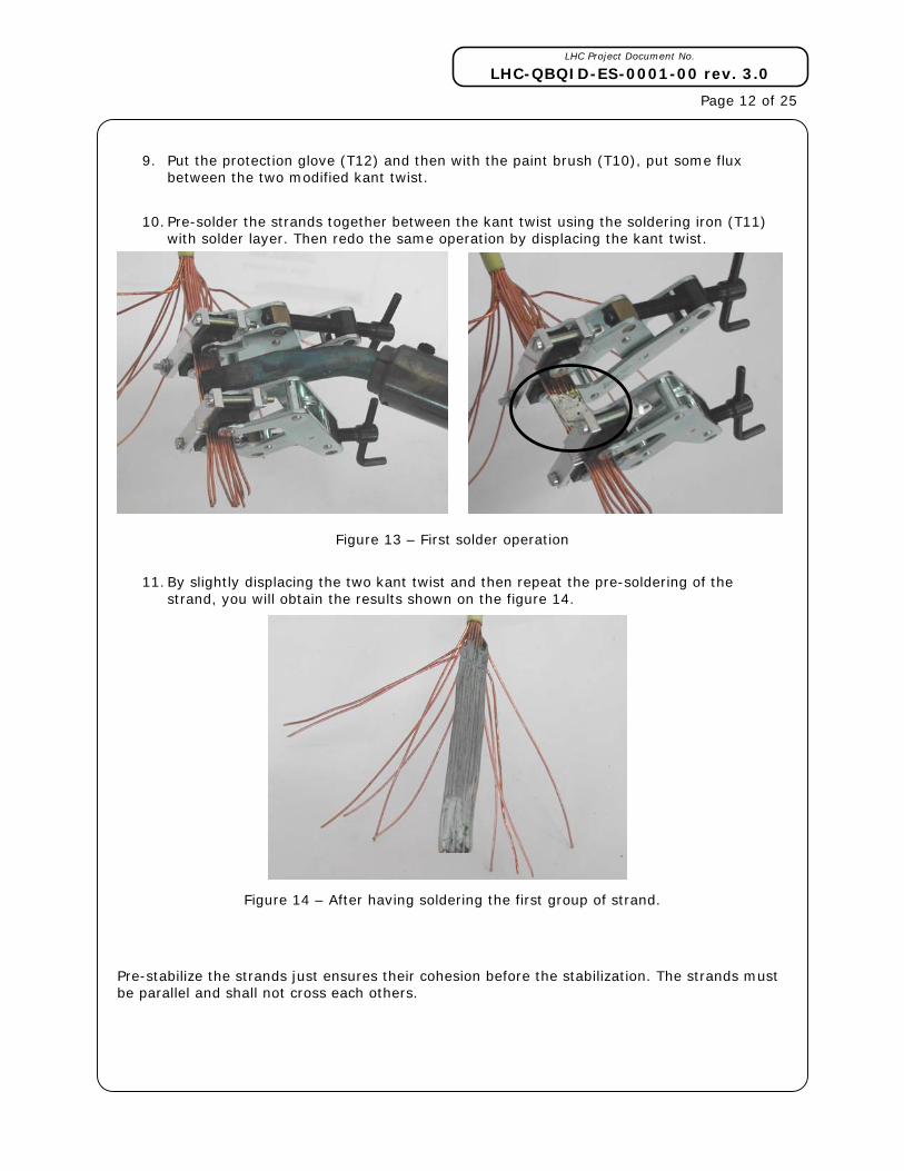
9. Put the protection glove (T12) and then with the paint brush (T10), put some flux between the two modified kant twist.
10. Pre-solder the strands together between the kant twist using the soldering iron (T11) with solder layer. Then redo the same operation by displacing the kant twist.
Figure 13 – First solder operation
11. By slightly displacing the two kant twist and then repeat the pre-soldering of the strand, you will obtain the results shown on the figure 14.
Figure 14 – After having soldering the first group of strand.
Pre-stabilize the strands just ensures their cohesion before the stabilization. The strands must be parallel and shall not cross each others.
LHC Project Document No.
LHC-QBQID-ES-0001-00 rev. 3.0
Page 13 of 25
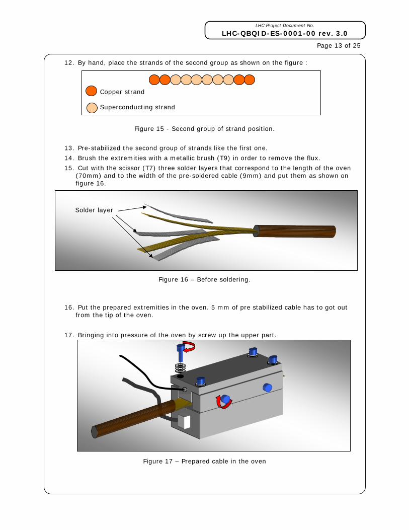
12. By hand, place the strands of the second group as shown on the figure :
Figure 15 - Second group of strand position.
13. Pre-stabilized the second group of strands like the first one.
14. Brush the extremities with a metallic brush (T9) in order to remove the flux.
15. Cut with the scissor (T7) three solder layers that correspond to the length of the oven (70mm) and to the width of the pre-soldered cable (9mm) and put them as shown on figure 16.
Figure 16 – Before soldering.
16. Put the prepared extremities in the oven. 5 mm of pre stabilized cable has to got out from the tip of the oven.
17. Bringing into pressure of the oven by screw up the upper part.
Figure 17 – Prepared cable in the oven
Copper strand Superconducting strand
Solder layer

LHC Project Document No.
LHC-QBQID-ES-0001-00 rev. 3.0
Page 14 of 25
18. Switch on the oven. The temperature increase until 226°C and is stabilized between 226°C and 230°C during 15 second.
19. Stop the heating.
20. Place the brands that go out from the oven using the flat nose pliers. The final prepared length has to be as long as possible.
21. Wait until the temperature is lower than 100°C.
22. Extract the cable from the oven and check the result by visual inspection. Solder must be present between each strand and equally spread.
23. Brush the extremity with a metallic brush (T9) in order to remove the flux.
6. INSERTION OF THE 6 KA BUS BAR IN THE LINE N
After the 6KA Bus Bar preparation, the cables have to be inserted in the line N in the tunnel. This installation is explained in reference [2].
7. RESISTIVE SOLDERING OF THE 6KA BUS BAR
7.1 RESISTIVE SOLDERING DEVICE (PORTABLE OVEN)
The resistive soldering installation consists of an oven equipped with a heating resistance powered by a generator. The cables to be joined are situated in the oven. The temperature must be controlled in real time to avoid degrading the superconductive properties (see figure 18). That’s why a temperature sensor has to be placed as closed as possible from the soldering zone. A pressure has to be applied to the oven. To ensure a repeatable quality of the soldered joints, the pressure shall be kept within the range (10±0.5) MPa for each splice.
Figure 18 - Resistive soldering system synoptic
Oven
PC controlled
generator
Electrical resistance
Temperature sensor
Data acquisition
LHC Project Document No.
LHC-QBQID-ES-0001-00 rev. 3.0
Page 15 of 25
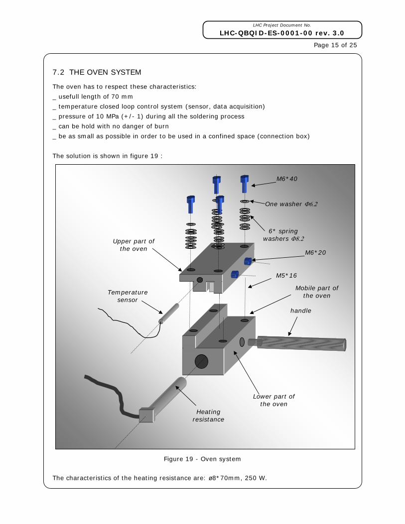
7.2 THE OVEN SYSTEM
The oven has to respect these characteristics:
_ usefull length of 70 mm
_ temperature closed loop control system (sensor, data acquisition)
_ pressure of 10 MPa (+/- 1) during all the soldering process
_ can be hold with no danger of burn
_ be as small as possible in order to be used in a confined space (connection box)
The solution is shown in figure 19 :
Figure 19 - Oven system
The characteristics of the heating resistance are: ø8*70mm, 250 W.
Heating resistance
Lower part of the oven
6* spring washers Φ8.2
M6*40
One washer Φ6.2
Upper part of the oven
handle
Mobile part of the oven
M5*16
Temperature sensor
M6*20

LHC Project Document No.
LHC-QBQID-ES-0001-00 rev. 3.0
Page 16 of 25
7.3 TOOLS NEEDED
T1 _ Generator and the heating resistance
T2 _ The oven and the pressure tools See chapter 7.1
T14 _ Protection plate system.
T15 _ cupper sheet for 6KA connection
T16 _ 10mm wrench.
T3
_ Flat nose plier
SCEM: 34.76.15.160.6
T7
_ Scissor
SCEM: 54.21.24.004.3
T10 _ Metallic Brush
SCEM: 34.90.20.012.4
T11
_ Flux with a brush
SCEM: 34.90.80.015.1
T13 _ protection gloves
In order to perform this preparation you will also need:
_ solder layer Sn96Ag4 0.4*10mm in ribbon and in wire.
_ soldering Flux (Kester)
_ Polyimide (Kapton) tape (scem: 04.94.70.100.3)
_ Glass fiber ribbon.
_ Kapton tube
LHC Project Document No.
LHC-QBQID-ES-0001-00 rev. 3.0
Page 17 of 25
7.4 SOLDERING PROCEDURE
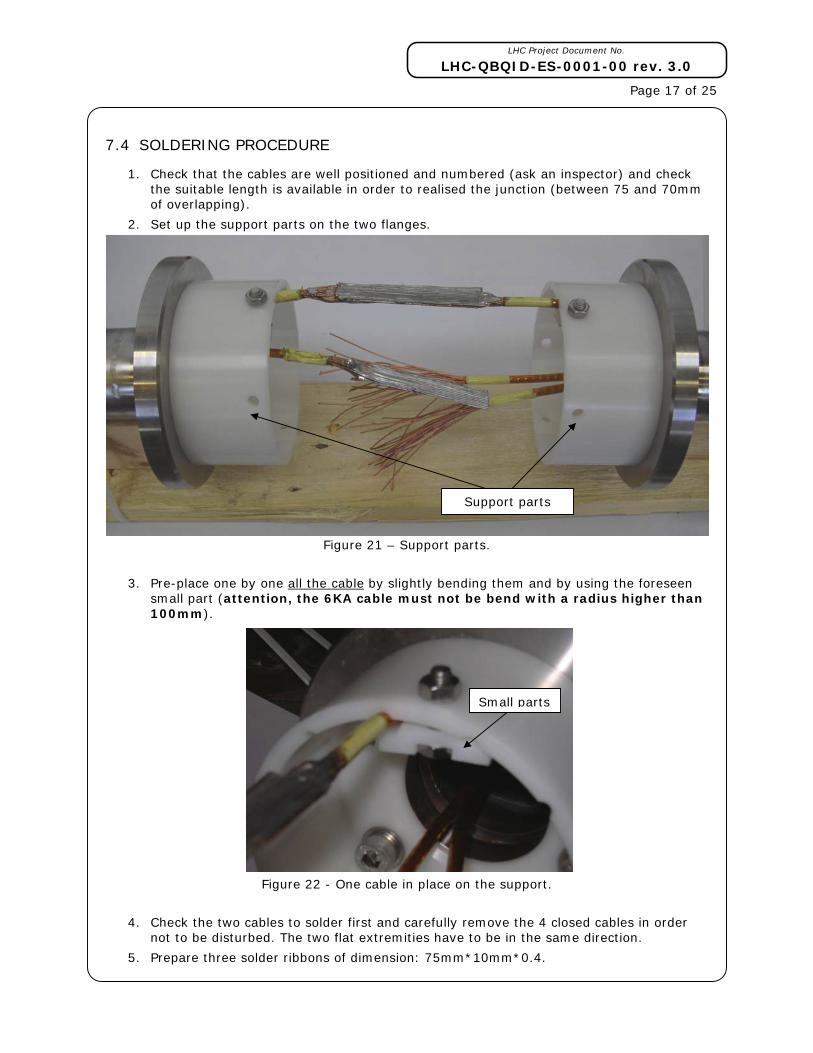
1. Check that the cables are well positioned and numbered (ask an inspector) and check the suitable length is available in order to realised the junction (between 75 and 70mm of overlapping).
2. Set up the support parts on the two flanges.
Figure 21 – Support parts.
3. Pre-place one by one all the cable by slightly bending them and by using the foreseen small part (attention, the 6KA cable must not be bend with a radius higher than 100mm).
Figure 22 - One cable in place on the support.
4. Check the two cables to solder first and carefully remove the 4 closed cables in order not to be disturbed. The two flat extremities have to be in the same direction.
5. Prepare three solder ribbons of dimension: 75mm*10mm*0.4.
Support parts
Small parts

LHC Project Document No.
LHC-QBQID-ES-0001-00 rev. 3.0
Page 18 of 25
6. Prepare one pre-bent copper sheet.
7. Put some flux on the cable and then place the solder ribbons and the copper sheet as shown on the following picture.
Figure 23- Junction assembly
Figure 24– Junction assembly
8. Press the assembly with the flat nose pliers T3.
Figure 25 - Pressed junction assembly
Solder layer
copper sheet

LHC Project Document No.
LHC-QBQID-ES-0001-00 rev. 3.0
Page 19 of 25
9. Put the junction on the oven as shown. Do not forget to put the resistance inside.
Figure 26 – Junction positioning
10. Install the upper part of the oven. Begin to screw up the fourth upper screw until the washer begins to flat. Then screw up the side screws and finally finish to screwing up the first four until the washers are totally flat.
Figure 27 - Oven in position
11. Put in place the alimentation and the temperature sensor.
12. Put a fumes extraction system as close as possible from the oven.
13. Check the assembly and the cable to interconnect.
14. Put a cotton rag under the oven, so that the liquefy solder to not leak on other prepared cables
15. Switch on the oven power supply.
16. Temperature increase until 226°C. During the solder liquefying check that the washers always press the junction.
17. Temperature stabilization between 226°C and 230°C during 15 seconds.
18. Stop the heating and wait until the temperature is lower than 100°C.
19. Create an .xls files containing the record of the temperature during the soldering operation.
20. Check that the washers always press the junction.
LHC Project Document No.
LHC-QBQID-ES-0001-00 rev. 3.0
Page 20 of 25
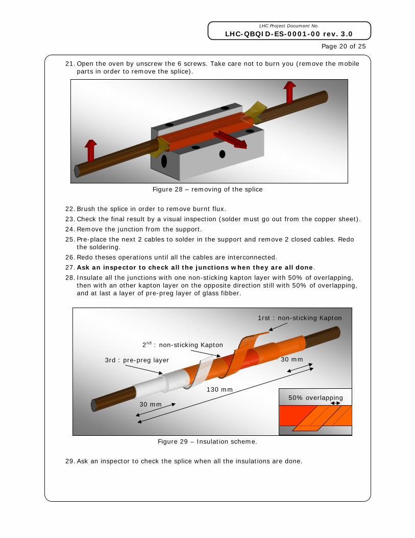
21. Open the oven by unscrew the 6 screws. Take care not to burn you (remove the mobile parts in order to remove the splice).
Figure 28 – removing of the splice
22. Brush the splice in order to remove burnt flux.
23. Check the final result by a visual inspection (solder must go out from the copper sheet).
24. Remove the junction from the support.
25. Pre-place the next 2 cables to solder in the support and remove 2 closed cables. Redo the soldering.
26. Redo theses operations until all the cables are interconnected.
27. Ask an inspector to check all the junctions when they are all done.
28. Insulate all the junctions with one non-sticking kapton layer with 50% of overlapping, then with an other kapton layer on the opposite direction still with 50% of overlapping, and at last a layer of pre-preg layer of glass fibber.
Figure 29 – Insulation scheme.
29. Ask an inspector to check the splice when all the insulations are done.
130 mm
30 mm
2nd : non-sticking Kapton
1rst : non-sticking Kapton
30 mm 3rd : pre-preg layer
50% overlapping

LHC Project Document No.
LHC-QBQID-ES-0001-00 rev. 3.0
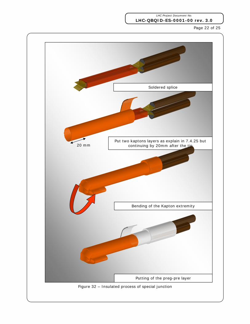
Page 21 of 25 7.5 SPECIAL CASE OF SOLDERING
In some case in the DS zone, the two cables to solder come from the same side as shown in the figure 30.
Figure 30 - Special case.
In that case, all the process of soldering is the same, except for the supporting system and for the insulation where it is quite more complicated.
Figure 31 – soldered special junction
LHC Project Document No.
LHC-QBQID-ES-0001-00 rev. 3.0
Page 22 of 25
Figure 32 – Insulated process of special junction
Soldered splice
Put two kaptons layers as explain in 7.4.25 but continuing by 20mm after the tip
Bending of the Kapton extremity
Putting of the preg-pre layer
20 mm

LHC Project Document No.
LHC-QBQID-ES-0001-00 rev. 3.0
Page 23 of 25 7.6 CONNECTION BOX WITH 12 OR 9 JUNCTIONS
Within the DS zone, 10 connection boxes contain 12 or 9 junctions of 6kA cable. The high number of junctions involves carefulness to perform them without problem. On the following figure the cables are shown only in one side to be as clear as possible.
Figure 33 – 12 junctions connection
All the junctions have to be executed carefully.
After the last junction, re-place all the junctions on the support parts and screw up the 6 hexagon nuts that keep tight the cable.
LHC Project Document No.
LHC-QBQID-ES-0001-00 rev. 3.0
Page 24 of 25
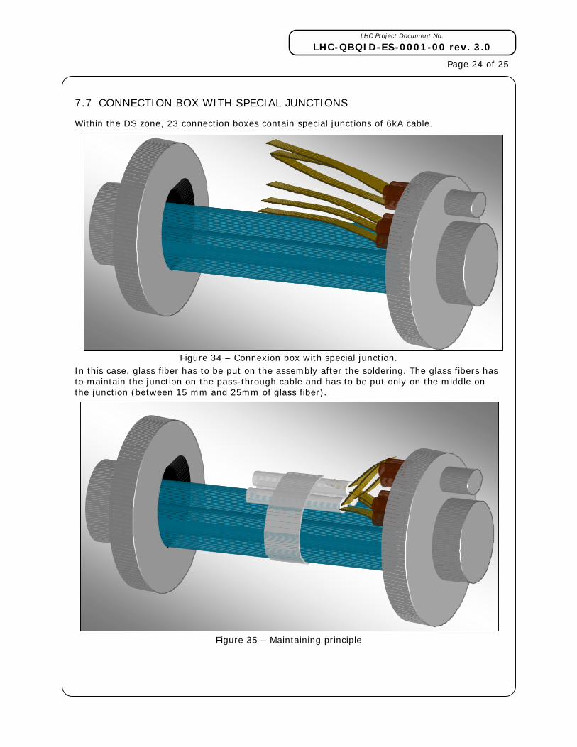
7.7 CONNECTION BOX WITH SPECIAL JUNCTIONS
Within the DS zone, 23 connection boxes contain special junctions of 6kA cable.
Figure 34 – Connexion box with special junction. In this case, glass fiber has to be put on the assembly after the soldering. The glass fibers has to maintain the junction on the pass-through cable and has to be put only on the middle on the junction (between 15 mm and 25mm of glass fiber).
Figure 35 – Maintaining principle

LHC Project Document No.
LHC-QBQID-ES-0001-00 rev. 3.0
Page 25 of 25
List of drawings [1] LHCQBQID0004 SSS-DFBA INTERCONNECTION (Q7-DFBA) – CONNECTION BOX 6 KA
[2] In Work
[3] In Work
[4] In Work
[5] In Work
[6] In Work
[7] In Work
[8] In Work
[9] LHCQBQID005 MB-SSS INTERCO. ZONE DS(MB-Q9) – CONNECTION BOX(600 A, 6 KA)
8. REFERENCE
[1] LHC-DC-ES-0003 Soldering flux applied to main bus-bar cables of the LHC
[2] In Work