resistencia de materiales
TRANSCRIPT

Thin-Walled Pressure Vessels A tank or pipe carrying a fluid or gas under a pressure is subjected to tensile forces,
which resist bursting, developed across longitudinal and transverse sections.
TANGENTIAL STRESS
(Circumferential Stress)
Consider the tank shown being subjected to an internal pressure p. The length of the
tank is L and the wall thickness is t. Isolating the right half of the tank:
If there exist an external pressure po and an internal pressure pi, the formula may be
expressed as:
LONGITUDINAL STRESS, σL
Consider the free body diagram in the transverse section of the tank:
The total force acting at the rear of the tank F must equal to the total longitudinal stress
on the wall PT = σL Awall. Since t is so small compared to D, the area of the wall is close
to πDt

If there exist an external pressure po and an internal pressure pi, the formula may be
expressed as:
It can be observed that the tangential stress is twice that of the longitudinal stress.
σt = 2 σL
SPHERICAL SHELL
If a spherical tank of diameter D and thickness t contains gas under
a pressure of p, the stress at the wall can be expressed as:

SOLVED PROBLEMS IN THIN WALLED PREASSURE VESSELS
Problem 133
A cylindrical steel pressure vessel 400 mm in diameter with a wall thickness of 20 mm,
is subjected to an internal pressure of 4.5 MN/m2. (a) Calculate the tangential and
longitudinal stresses in the steel. (b) To what value may the internal pressure be
increased if the stress in the steel is limited to 120 MN/m2? (c) If the internal pressure
were increased until the vessel burst, sketch the type of fracture that would occur.
Solution 133

Problem 134
The wall thickness of a 4-ft-diameter spherical tank is 5/16 in. Calculate the allowable
internal pressure if the stress is limited to 8000 psi.
Solution 134
Problem 135
Calculate the minimum wall thickness for a cylindrical vessel that is to carry a gas at a
pressure of 1400 psi. The diameter of the vessel is 2 ft, and the stress is limited to 12
ksi.
Solution 135

Problem 136
A cylindrical pressure vessel is fabricated from steel plating that has a thickness of 20
mm. The diameter of the pressure vessel is 450 mm and its length is 2.0 m. Determine
the maximum internal pressure that can be applied if the longitudinal stress is limited to
140 MPa, and the circumferential stress is limited to 60 MPa.
Solution 136

Problem 137
A water tank, 22 ft in diameter, is made from steel plates that are ½ in. thick. Find the
maximum height to which the tank may be filled if the circumferential stress is limited
to 6000 psi. The specific weight of water is 62.4 lb/ft3.
Solution 137

Problem 138
The strength of longitudinal joint in Fig. 1-17 is 33 kips/ft, whereas for the girth is 16
kips/ft. Calculate the maximum diameter of the cylinder tank if the internal pressure is
150 psi.
Solution 138

Problem 139
Find the limiting peripheral velocity of a rotating steel ring if the allowable stress is 20
ksi and steel weighs 490 lb/ft3. At what revolutions per minute (rpm) will the stress
reach 30 ksi if the mean radius is 10 in.?
Solution 139
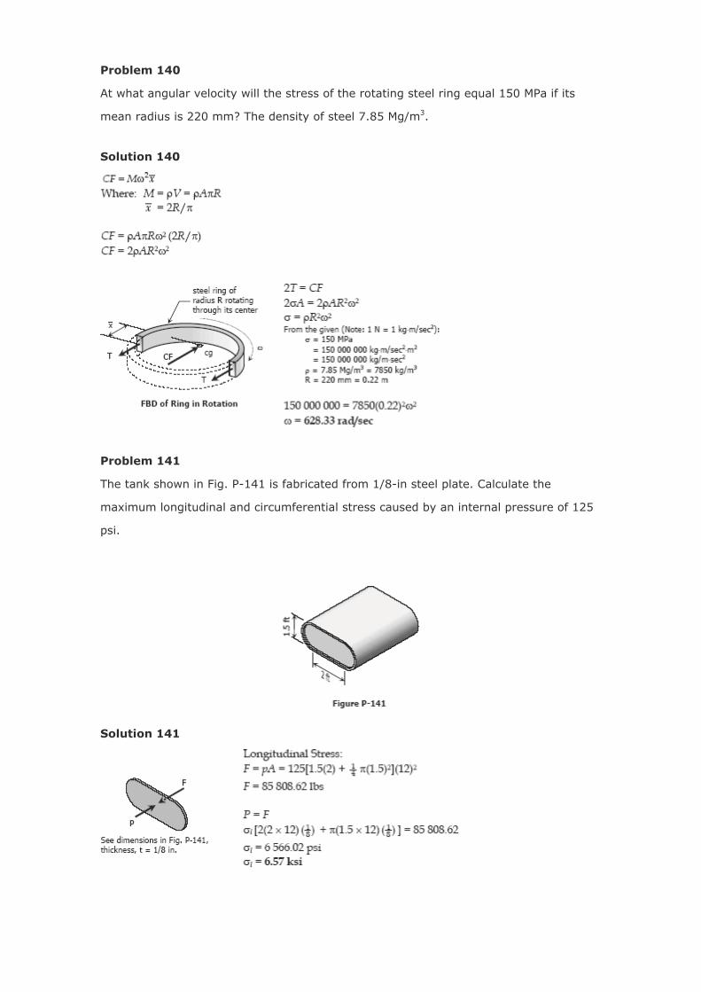
Problem 140
At what angular velocity will the stress of the rotating steel ring equal 150 MPa if its
mean radius is 220 mm? The density of steel 7.85 Mg/m3.
Solution 140
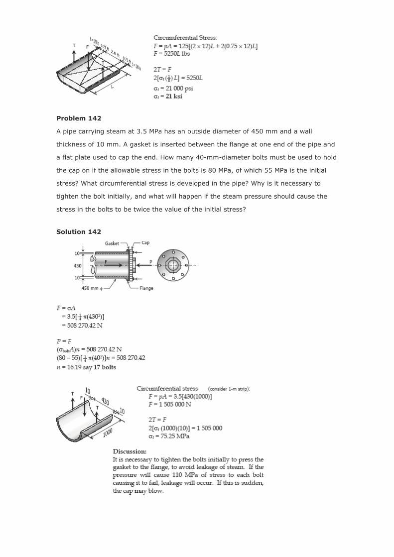
Problem 141
The tank shown in Fig. P-141 is fabricated from 1/8-in steel plate. Calculate the
maximum longitudinal and circumferential stress caused by an internal pressure of 125
psi.
Solution 141
Problem 142
A pipe carrying steam at 3.5 MPa has an outside diameter of 450 mm and a wall
thickness of 10 mm. A gasket is inserted between the flange at one end of the pipe and
a flat plate used to cap the end. How many 40-mm-diameter bolts must be used to hold
the cap on if the allowable stress in the bolts is 80 MPa, of which 55 MPa is the initial
stress? What circumferential stress is developed in the pipe? Why is it necessary to
tighten the bolt initially, and what will happen if the steam pressure should cause the
stress in the bolts to be twice the value of the initial stress?
Solution 142

Flanged Bolt Couplings
In shaft connection called flanged bolt couplings (see figure above), the torque is
transmitted by the shearing force P created in he bolts that is assumed to be uniformly
distributed. For any number of bolts n, the torque capacity of the coupling is
If a coupling has two concentric rows of bolts, the torque capacity
is
where the subscript 1 refer to bolts on the outer circle an
subscript 2 refer to bolts on the inner circle. See figure.
For rigid flanges, the shear deformations in the bolts are proportional to their radial
distances from the shaft axis. The shearing strains are related by
Using Hooke’s law for shear, G = τ / γ, we have
If the bolts on the two circles have the same area, A1 = A2, and if the bolts are made of
the same material, G1 = G2, the relation between P1 and P2 reduces to
Solved Problems in Flanged Bolt Couplings
Problem 326
A flanged bolt coupling consists of ten 20-mmdiameter bolts spaced evenly around a
bolt circle 400 mm in diameter. Determine the torque capacity of the coupling if the
allowable shearing stress in the bolts is 40 MPa.
Solution 326
Problem 327
A flanged bolt coupling consists of ten steel ½ -in.-diameter bolts spaced evenly around
a bolt circle 14 in. in diameter. Determine the torque capacity of the coupling if the
allowable shearing stress in the bolts is 6000 psi.
Solution 327
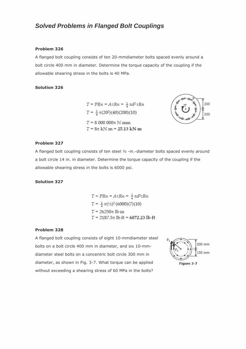
Problem 328
A flanged bolt coupling consists of eight 10-mmdiameter steel
bolts on a bolt circle 400 mm in diameter, and six 10-mm-
diameter steel bolts on a concentric bolt circle 300 mm in
diameter, as shown in Fig. 3-7. What torque can be applied
without exceeding a shearing stress of 60 MPa in the bolts?

Solution 328
Problem 329
A torque of 700 lb-ft is to be carried by a flanged bolt coupling that consists of eight ½ -
in.-diameter steel bolts on a circle of diameter 12 in. and six ½ -in.-diameter steel bolts
on a circle of diameter 9 in. Determine the shearing stress in the bolts.
Solution 329

Problem 330
Determine the number of 10-mm-diameter steel bolts that must be used on the 400-
mm bolt circle of the coupling described in Prob. 328 to increase the torque capacity to
14 kN·m
Solution 330
Problem 331
A flanged bolt coupling consists of six ½ -in. steel bolts evenly spaced around a bolt
circle 12 in. in diameter, and four ¾ -in. aluminum bolts on a concentric bolt circle 8 in.
in diameter. What torque can be applied without exceeding 9000 psi in the steel or
6000 psi in the aluminum? Assume Gst = 12 × 106 psi and Gal = 4 × 10⁶ psi.
Solution 331

Problem 332
In a rivet group subjected to a twisting couple T, show that the torsion formula τ = Tρ/J
can be used to find the shearing stress t at the center of any rivet. Let J = ΣAρ2, where
A is the area of a rivet at the radial distance ρ from the centroid of the rivet group.
Solution 332
Problem 333
A plate is fastened to a fixed member by four 20-mm diameter rivets arranged as
shown in Fig. P-333. Compute the maximum and minimum shearing stress developed.

Solution 333
Problem 334
Six 7/8-in-diameter rivets fasten the plate in Fig. P-334 to the fixed member. Using the
results of Prob. 332, determine the average shearing stress caused in each rivet by the
14 kip loads. What additional loads P can be applied before the shearing stress in any
rivet exceeds 8000 psi?
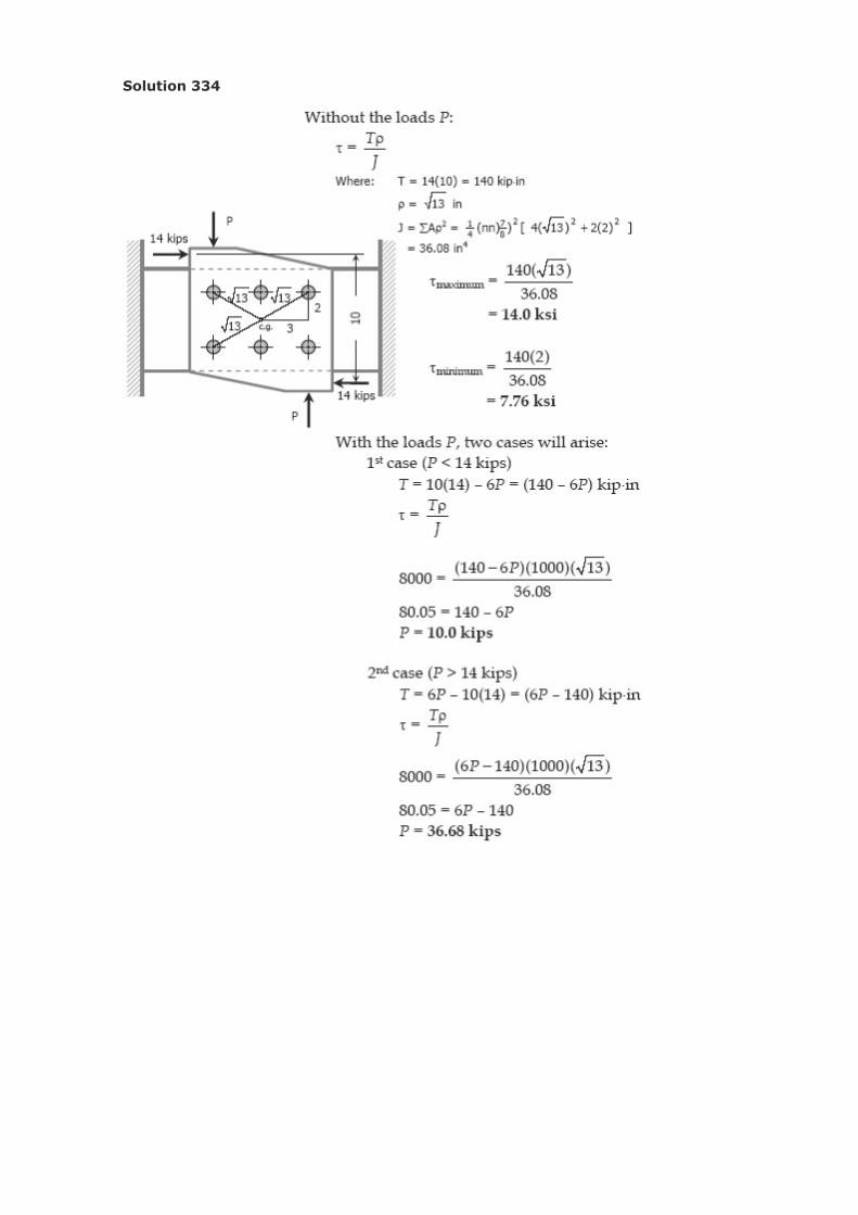
Solution 334

Problem 335
The plate shown in Fig. P-335 is fastened to the fixed member by five 10-mm-diameter
rivets. Compute the value of the loads P so that the average shearing stress in any rivet
does not exceed 70 MPa. (Hint: Use the results of Prob. 332.)
Solution 335
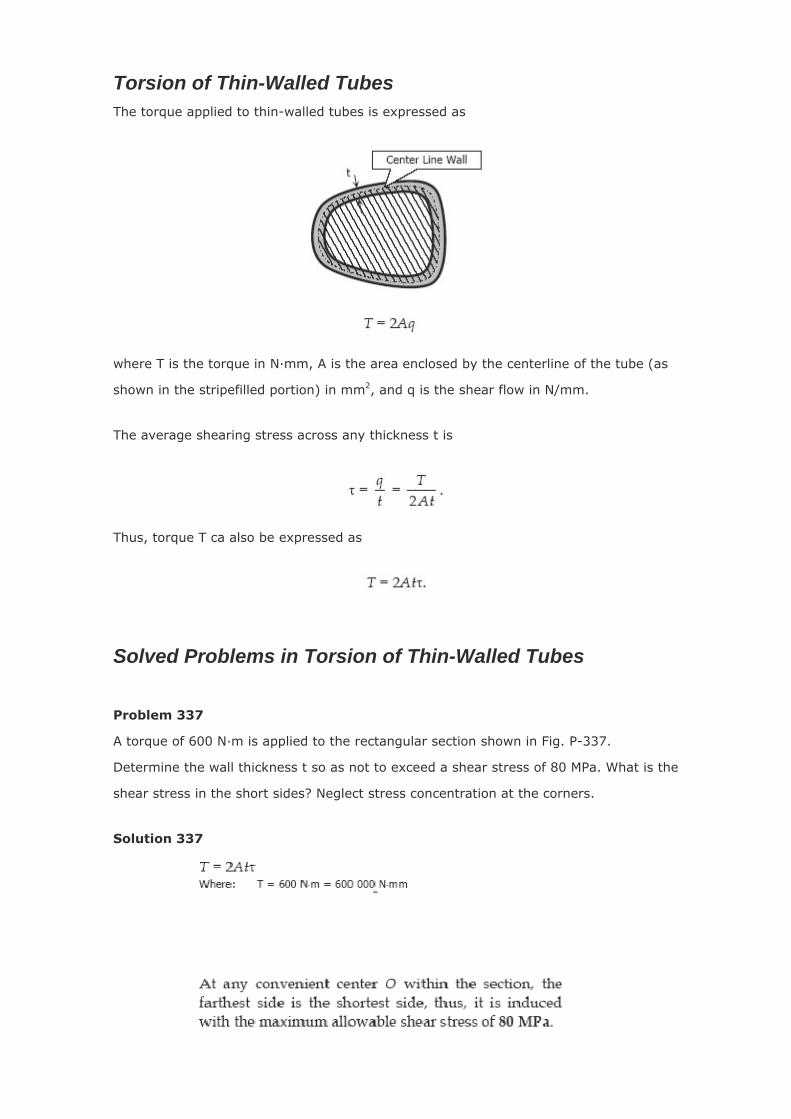
Torsion of Thin-Walled Tubes The torque applied to thin-walled tubes is expressed as
where T is the torque in N·mm, A is the area enclosed by the centerline of the tube (as
shown in the stripefilled portion) in mm2, and q is the shear flow in N/mm.
The average shearing stress across any thickness t is
Thus, torque T ca also be expressed as
Solved Problems in Torsion of Thin-Walled Tubes
Problem 337
A torque of 600 N·m is applied to the rectangular section shown in Fig. P-337.
Determine the wall thickness t so as not to exceed a shear stress of 80 MPa. What is the
shear stress in the short sides? Neglect stress concentration at the corners.
Solution 337

Problem 338
A tube 0.10 in. thick has an elliptical shape shown in Fig.
P-338. What torque will cause a shearing stress of 8000
psi?
Solution 338
Problem 339
A torque of 450 lb·ft is applied to the square section shown in Fi
P-339. Determine the smallest permissi
g.
ble dimension a if the
shearing stress is limited to 6000 psi.
Solution 339
Problem 340
A tube 2 mm thick has the shape shown in Fig. P-340. Find
the shearing stress caused by a torque of 600 N·m.
Solution 340

Problem 341
Derive the torsion formula τ = Tρ/J for a solid circular section by assuming the section is
composed of a series of concentric thin circular tubes. Assume that the shearing stress
at any point is proportional to its radial distance.
Solution 341