resistance heating alloys and systems for industrial furnaces
TRANSCRIPT
ResistanceHeatingAlloys andSystemsfor IndustrialFurnaces

Catalogue 1-A-5B-3 US 11-07-3000
© Kanthal AB.May be reproduced only with proper acknowledgement of the source. Disclaimer: The information contained in this document is for illustrative purposes only. The data and examples are only general recommendations, and not a warranty or a guarantee that such data will function in individual/specific cases. The purchaser of a Kanthal product has the responsibility to control the applicability of Kanthal’s products in a specific application before using them.
® KANTHAL, NIKROTHAL, TUBOTHAL and ECOTHAL are registered trademarks of Kanthal Group companies in Sweden and other countries.
Contents PageMetallic Heating Elements from Kanthal ..........................................................................................................4
KANTHAL® or NIKROTHAL®? .........................................................................................................................5
KANTHAL APM™ Heating Material ...............................................................................................................6
Physical and Mechanical Properties ...................................................................................................................7
Furnace Wall Loading ...........................................................................................................................................8
Element Surface Load ...........................................................................................................................................9
Operating Life and Maximum Permissible Temperature ............................................................................10
Key Data for Kanthal Elements ........................................................................................................................12
Kanthal TUBOTHAL® – the Most Powerful Metallic Element System ..................................................14
KANTHAL PM Material .....................................................................................................................................16
Gas Fired Systems ................................................................................................................................................18
KANTHAL APM Standard Product Range ....................................................................................................20
Tables
KANTHAL A-1 and APM......................................................................................................................23
KANTHAL AF .........................................................................................................................................24
KANTHAL D ...........................................................................................................................................25
NIKROTHAL 80 ......................................................................................................................................26
NIKROTHAL 70 ......................................................................................................................................27
Terminals ...................................................................................................................................................28
ResistanceHeatingAlloysandSystemsforIndustrialFurnaces
MetallicHeatingElementsfromKanthal
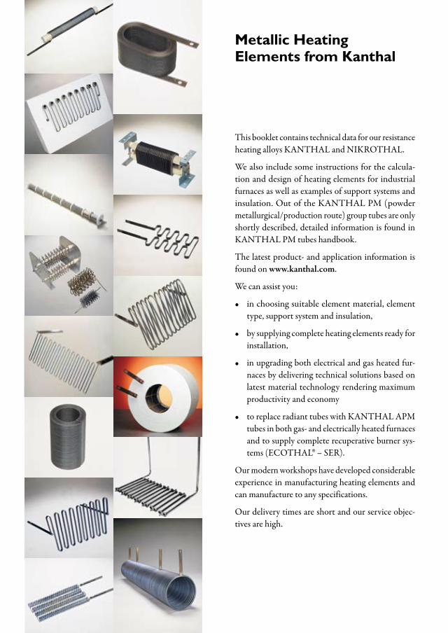
This booklet contains technical data for our resistance heating alloys KANTHAL and NIKROTHAL.
We also include some instructions for the calcula-tion and design of heating elements for industrial furnaces as well as examples of support systems and insulation. Out of the KANTHAL PM (powder metallurgical/production route) group tubes are only shortly described, detailed information is found in KANTHAL PM tubes handbook.
The latest product- and application information is found on www.kanthal.com.
We can assist you:
in choosing suitable element material, element type, support system and insulation,
by supplying complete heating elements ready for installation,
in upgrading both electrical and gas heated fur-naces by delivering technical solutions based on latest material technology rendering maximum productivity and economy
to replace radiant tubes with KANTHAL APM tubes in both gas- and electrically heated furnaces and to supply complete recuperative burner sys-tems (ECOTHAL® – SER).
Our modern workshops have developed considerable experience in manufacturing heating elements and can manufacture to any specifications.
Our delivery times are short and our service objec-tives are high.
•
•
•
•
5
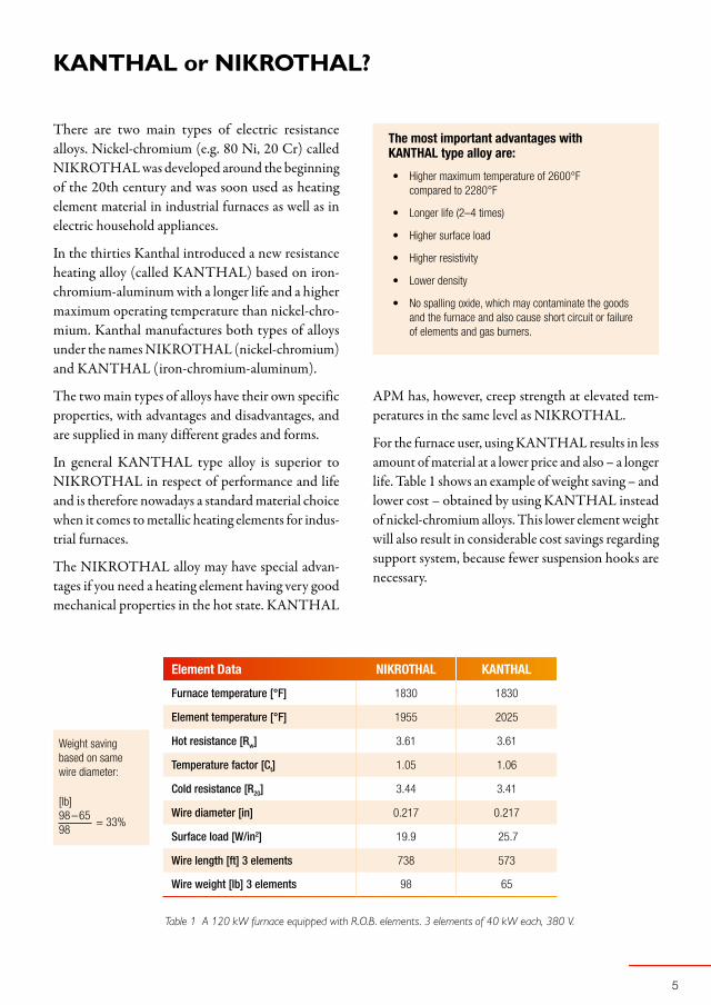
Element Data NIKROTHAL KANTHAL
Furnace temperature [°F] 1830 1830
Element temperature [°F] 1955 2025
Hot resistance [Rw] 3.61 3.61
Temperature factor [Ct] 1.05 1.06
Cold resistance [R20] 3.44 3.41
Wire diameter [in] 0.217 0.217
Surface load [W/in2] 19.9 25.7
Wire length [ft] 3 elements 738 573
Wire weight [lb] 3 elements 98 65
98 – 65 = 33%98
Weight saving based on same wire diameter:
[lb]
There are two main types of electric resistance alloys. Nickel-chromium (e.g. 80 Ni, 20 Cr) called NIKROTHAL was developed around the beginning of the 20th century and was soon used as heating element material in industrial furnaces as well as in electric household appliances.
In the thirties Kanthal introduced a new resistance heating alloy (called KANTHAL) based on iron-chromium-aluminum with a longer life and a higher maximum operating temperature than nickel-chro-mium. Kanthal manufactures both types of alloys under the names NIKROTHAL (nickel-chromium) and KANTHAL (iron-chromium-aluminum).
The two main types of alloys have their own specific properties, with advantages and disadvantages, and are supplied in many different grades and forms.
In general KANTHAL type alloy is superior to NIKROTHAL in respect of performance and life and is therefore nowadays a standard material choice when it comes to metallic heating elements for indus-trial furnaces.
The NIKROTHAL alloy may have special advan-tages if you need a heating element having very good mechanical properties in the hot state. KANTHAL
KANTHALorNIKROTHAL?
Table 1 A 120 kW furnace equipped with R.O.B. elements. 3 elements of 40 kW each, 380 V.
The most important advantages with KANTHAL type alloy are:
Higher maximum temperature of 2600°F compared to 2280°F
Longer life (2–4 times)
Higher surface load
Higher resistivity
Lower density
No spalling oxide, which may contaminate the goods and the furnace and also cause short circuit or failure of elements and gas burners.
•
•
•
•
•
•
APM has, however, creep strength at elevated tem-peratures in the same level as NIKROTHAL.
For the furnace user, using KANTHAL results in less amount of material at a lower price and also – a longer life. Table 1 shows an example of weight saving – and lower cost – obtained by using KANTHAL instead of nickel-chromium alloys. This lower element weight will also result in considerable cost savings regarding support system, because fewer suspension hooks are necessary.
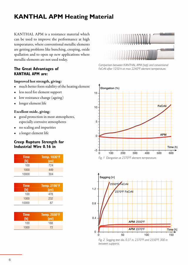
Time Temp. 1830°F[h] [psi]100 724
1000 44910000 304
Time Temp. 2190°F[h] [psi]100 478
1000 23210000 87
Time Temp. 2550°F[h] [psi]100 188
1000 72
2550ºF FeCrAl
2550ºF
2370ºF FeCrAl
2370ºF
0.4
0.8
1.2
[in]
[h]
KANTHALAPMHeatingMaterial
KANTHAL APM is a resistance material which can be used to improve the performance at high temperatures, where conventional metallic elements are getting problems like bunching, creeping, oxide spallation and to open up new applications where metallic elements are not used today.
The Great Advantages of KANTHAL APM are:
Improved hot strength, giving:much better form stability of the heating elementless need for element supportlow resistance change (ageing)longer element life
Excellent oxide, giving:good protection in most atmospheres, especially corrosive atmospheresno scaling and impuritiesa longer element life
Creep Rupture Strength for Industrial Wire 0.16 in
••••
•
••
Comparison between KANTHAL APM (top) and conventional FeCrAl after 1250 h at max 2240°F element temperature.
Fig. 1 Elongation at 2370°F element temperature.
Fig. 2 Sagging test dia. 0.37 in, 2370°F and 2550°F, 300 in between supports.

7
PhysicalandMechanicalProperties
KANTHAL and NIKROTHAL alloys are generally available in wire, ribbon or strip form. Physical and mechanical properties of the alloys are listed in Table 2. Ct factor see page 23 and following.
Table 2 KANTHAL and NIKROTHAL basic data.
KANTHAL APM
KANTHAL A-1
KANTHAL AF
KANTHAL D
NIKROTHAL 80
NIKROTHAL 70
NIKROTHAL 60
NIKROTHAL 40
Max continuous operating temp. [°F] 2600 2550 2370 2370 2190 2280 2100 2010
Nominal composition % Cr 22 22 22 22 20 30 15 20
Al 5.8 5.8 5.3 4.8 – – – –
Fe Balance Balance Balance Balance – 5 % Balance Balance
Ni – – – – Balance Balance 60 35
Resistivity at 68°F [Ω/cmf] 872 872 836 842 655 704 668 626
Density [lb/in3] 0.256 0.256 0.259 0.262 0.300 0.296 0.296 .0285
Coefficient of 68 –1380°F 14 × 10-6 14 × 10-6 14× 10-6 14 × 10-6 16 × 10-6 16 × 10-6 16 × 10-6 18 × 10-6
thermal expansion, K-1 68 –1830°F 15 × 10-6 15 × 10-6 15 × 10-6 15 × 10-6 17 × 10-6 17 × 10-6 17 × 10-6 19 × 10-6
Thermal conductivity at 68°F [W in-1 F-1] 0.18 0.18 0.18 0.18 0.21 0.18 0.18 0.18
Specific heat capacity at 68°F [Btu lb-1 F-1] 0.110 0.110 0.110 0.110 0.110 0.110 0.110 0.119
Melting point [°F] 2730 2730 2730 2730 2550 2515 2535 2535
Mechanical properties (approx.)*
Tensile strength [psi] 99000 99000 99000 95000 118000 119000 106000 98000
Yield point [psi] 68000 69000 69000 66000 61000 63000 54000 49000
Hardness [Hv] 230 230 230 230 180 185 180 180
Elongation at rupture [%] 20 18 18 18 30 30 35 35
Tensile strength at 1650°F [psi] 5800 4900 5400 4900 15000 17000 15000 17000
Creep strength at 1470°F [psi] 1600 870 1200 870 2200 2200 2200 2900
Creep strength at 1830°F [psi] 490 145 220 145 580 580 580 580
Magnetic properties Magnetic (Curie point 1100°F) Non Non Slightly Non
Emissivity, fully oxidized condition 0.70 0.70 0.70 0.70 0.88 0.88 0.88 0.88
*) The values given apply for wire sizes of 0.16 in diameter for Kanthal alloys and of 0.04 in for NIKROTHAL alloys.
10
9
8
7
5
6
4
3
2
1
kW/in²
1290 1470 1650 1830 2010 2190 2370 ºF
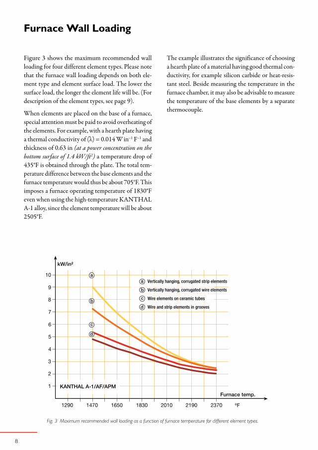
Figure 3 shows the maximum recommended wall loading for four different element types. Please note that the furnace wall loading depends on both ele-ment type and element surface load. The lower the surface load, the longer the element life will be. (For description of the element types, see page 9).
When elements are placed on the base of a furnace, special attention must be paid to avoid overheating of the elements. For example, with a hearth plate having a thermal conductivity of (λ) = 0.014 W in–1 F–1 and thickness of 0.63 in (at a power concentration on the bottom surface of 1.4 kW/ft2) a temperature drop of 435°F is obtained through the plate. The total tem-perature difference between the base elements and the furnace temperature would thus be about 705°F. This imposes a furnace operating temperature of 1830°F even when using the high-temperature KANTHAL A-1 alloy, since the element temperature will be about 2505°F.
FurnaceWallLoading
Vertically hanging, corrugated strip elements
Vertically hanging, corrugated wire elements
Wire elements on ceramic tubes
Wire and strip elements in grooves
Fig. 3 Maximum recommended wall loading as a function of furnace temperature for different element types.
The example illustrates the significance of choosing a hearth plate of a material having good thermal con-ductivity, for example silicon carbide or heat-resis-tant steel. Beside measuring the temperature in the furnace chamber, it may also be advisable to measure the temperature of the base elements by a separate thermocouple.
1470 1650 1830 2010 2190 2370 ºF 1470 1650 1830 2010 ºF
W/in²
20
10
30
40
50
60
70
W/in²
20
10
30
40
50
60
70
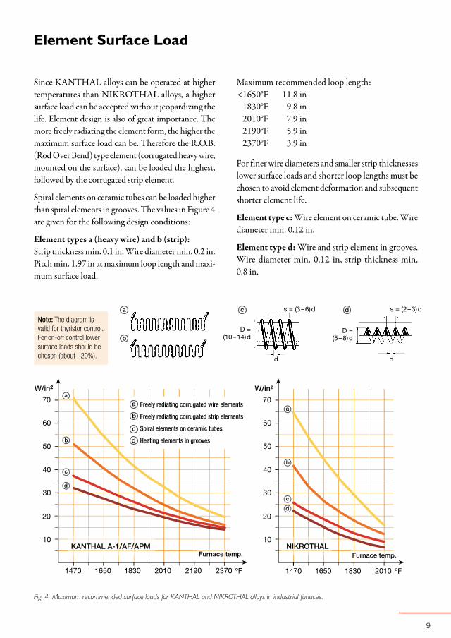
ElementSurfaceLoad
Since KANTHAL alloys can be operated at higher temperatures than NIKROTHAL alloys, a higher surface load can be accepted without jeopardizing the life. Element design is also of great importance. The more freely radiating the element form, the higher the maximum surface load can be. Therefore the R.O.B. (Rod Over Bend) type element (corrugated heavy wire, mounted on the surface), can be loaded the highest, followed by the corrugated strip element.
Spiral elements on ceramic tubes can be loaded higher than spiral elements in grooves. The values in Figure 4 are given for the following design conditions:
Element types a (heavy wire) and b (strip):Strip thickness min. 0.1 in. Wire diameter min. 0.2 in. Pitch min. 1.97 in at maximum loop length and maxi-mum surface load.
Note: The diagram is valid for thyristor control. For on-off control lower surface loads should be chosen (about –20%).
D = (5 – 8) d
Fig. 4 Maximum recommended surface loads for KANTHAL and NIKROTHAL alloys in industrial funaces.
Freely radiating corrugated wire elements
Freely radiating corrugated strip elements
Spiral elements on ceramic tubes
Heating elements in grooves
D = (10 – 14) d
s = (2 – 3) ds = (3 – 6) d
d d
Maximum recommended loop length: <1650°F 11.8 in 1830°F 9.8 in 2010°F 7.9 in 2190°F 5.9 in 2370°F 3.9 in
For finer wire diameters and smaller strip thicknesses lower surface loads and shorter loop lengths must be chosen to avoid element deformation and subsequent shorter element life.
Element type c: Wire element on ceramic tube. Wire diameter min. 0.12 in.
Element type d: Wire and strip element in grooves. Wire diameter min. 0.12 in, strip thickness min. 0.8 in.

10
OperatingLifeandMaximumPermissibleTemperature
1830 2010 2190 2370 ºF2550
When heated, resistance heating alloys form an oxide layer on their surface, which prevents further oxida-tion of the material. To accomplish this function the oxide layer must be dense and resist the diffusion of gases. It must also be thin and adhere to the metal under temperature fluctuations.
In these respects the aluminum oxide formed on KANTHAL alloys is might be even better than the oxide formed on NIKROTHAL alloys, which con-tributes to the much longer operating life of Kanthal heating elements. Figure 5 shows the comparative element life.
Below you will find some general advice to obtain as long element life as possible.
Use KANTHAL AlloysHeating elements made of KANTHAL alloys have 2–4 times longer life than heating elements made of nickel-chromium material. The higher the tempera-ture, the greater the difference.
Avoid Temperature FluctuationsThe operating life of the heating elements will be reduced by rapid temperature fluctuations. It is there-fore advisable to choose an electric control equip-ment, which gives as even a temperature as possible, e.g. by using thyristors.
Choose Thick Element MaterialThe material thickness has a direct relationship to the element life, in that, as the wire diameter is increased, more alloying element is available per surface unit to form a new oxide. Thus, at given temperature, thicker wires will give a longer life than thinner wires. Accord-ingly, for strip elements, increased thickness gives a longer life. As a general rule, we recommend min. 0.12 in wire diameter and 0.8 in strip thickness.
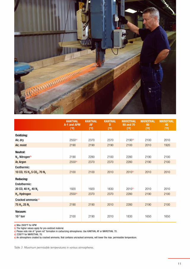
Adjust the Element Temperature to the Furnace AtmosphereTable 3 shows some common furnace atmospheres and their influence on the maximum operating tem-
KANTHAL APM
KANTHAL AF
KANTHAL A-1
KANTHAL D
NIKROTHAL 80
NIKROTHAL 60
NIKROTHAL 40
perature of the heating elements. NIKROTHAL should not be used in furnaces having a CO-con-taining protective gas atmosphere due to the risk of “green rot” at 1470–1740°F.
In such cases KANTHAL alloys are recommended, provided the heating elements are preoxidized in air at 1920°F for 7–10 hours. Reoxidation of the heating elements should be carried out at regular intervals.
Avoid Corrosion from Solid Substances, Fluids and GasesImpurities in the furnace atmosphere, for instance oil, dust, volatiles or carbon deposits can damage the heating elements.
Sulphur is harmful to all nickel alloys. Chlorine in different forms will attack both KANTHAL and NIKROTHAL alloys. Splashes of molten metal or salt may also damage the heating elements.
Fig. 5 Comparative life (KANTHAL A-1 at 2190°F = 100 %)
11
KANTHAL KANTHAL KANTHAL NIKROTHAL NIKROTHAL NIKROTHALA-1 and APM AF D 80 and 70 60 40
[°F] [°F] [°F] [°F] [°F] [°F]
Oxidizing:
Air, dry 2550(a) 2370 2370 2190(d) 2100 2010
Air, moist 2190 2190 2190 2100 2010 1920
Neutral:
N2, Nitrogen(b) 2190 2280 2100 2280 2190 2100
Ar, Argon 2550(a) 2370 2370 2280 2190 2100
Exothermic:
10 CO, 15 H2, 5 CO2, 70 N2 2100 2100 2010 2010(c) 2010 2010
Reducing:
Endothermic:
20 CO, 40 H2, 40 N2 1920 1920 1830 2010(c) 2010 2010
H2, Hydrogen 2550(a) 2370 2370 2280 2190 2100
Cracked ammonia:(e)
75 H2, 25 N2 2190 2190 2010 2280 2190 2100
Vacuum:
10-3 torr 2100 2190 2010 1830 1650 1650
a) Max 2600°F for APM b) The higher values apply for pre-oxidized material. c) Please note risk of “green rot” formation in carburizing atmospheres. Use KANTHAL AF or NIKROTHAL 70. d) 2280°F for NIKROTHAL 70. e) An atmosphere created by cracked ammonia, that contains uncracked ammonia, will lower the max. permissible temperature.
Table 3 Maximum permissible temperatures in various atmospheres.

12
Wire Elements
Element Systems Spiral Spiral Porcupine Rod over Bend
Supports Ceramic tubes Grooves Ceramic tubes Metallic rods
Material Sillimanite Chamotte Grade 28 Sillimanite KANTHAL APM
Max. furnance temperature [°F] 2370 2280 8147000 2370
Max. wall loading at 1830°Ffurnace temperature [kW/ft2] 3.7 3.3 – 4.6
Max. surface load at 1830°Ffurnace temperature [W/in2] 19 – 26 19 – 26 – 32 – 39
Wire diameter (d) [in] 0.08 – 0.26 0.08 – 1.97 0.04 – 0.26 ≥ 1.97
Strip thickness (t) [in] – – – –
Strip widht (w) [in] – – – –
Outer coil diameter (D) [in] (12 – 14) d (5 – 6) d – –
Max. loop length at 1830°Ffurnace temperature [in] – – – 9.8
Min. pitch at max. loop length [in] 3d 2d 3d 1.57
KeyDataforKanthalElements
Table 4

13
Strip Elements
Corrugated Looped Deep-Corrugated Deep-Corrugated Deep-Corrugated Corrugated
Metallic staples Ceramic tubes Ceramic cup locks Ceramic bushes Ceramic tubes Grooves
U-shaped Kanthal-nails Sillimanite Cordierite or Mullite Cordierite or Mullite Sillimanite Chamotte Grade 28
2370 2370 2370 2370 2370 2370
4.6 5.6 5.6 5.6 5.6 1.9 – 3.7
19 – 39 32 – 39 32 – 39 32 – 39 32 – 39 19 – 26
0.08 – 1.97 ≥ 1.97 – – – –
– – 0.08 – 0.12 0.08 – 0.12 0.08 – 0.12 0.06 – 0.12
– – (8 – 12) t (8 – 12) t (8 – 12) t (8 – 12) t
– – – – – –
3.9 9.8 9.8 9.8 9.8 (2 – 3) w
1.57 1.57 1.97 1.97 1.97 1.5 w
14
1470ºF2010 1830 1650(ft)
Ø 2.68 in
Ø 3.15 in
Ø 4.33 in
Ø 4.88 in
Ø 6.06 in
Ø 6.69 in
1 2 3 4 5 6 7 8 9 10
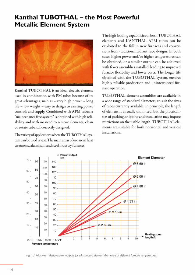
KanthalTUBOTHAL–theMostPowerfulMetallicElementSystem
Fig. 13 Maximum design power outputs for all standard element diameters at different furnace temperatures.
Kanthal TUBOTHAL is an ideal electric element used in combination with PM tubes because of its great advantages, such as – very high power – long life – low weight – easy to design to existing power controls and supply. Combined with APM tubes, a “maintenance free system” is obtained with high reli-ability and with no need to remove elements, clean or rotate tubes, if correctly designed.
The variety of applications where the TUBOTHAL sys-tem can be used is vast. The main areas of use are in heat treatment, aluminum and steel industry furnaces.
The high loading capabilities of both TUBOTHAL elements and KANTHAL APM tubes can be exploited to the full in new furnaces and conver-sions from traditional radiant tube designs. In both cases, higher power and/or higher temperatures can be obtained, or a similar output can be achieved with fewer assemblies installed, leading to improved furnace flexibility and lower costs. The longer life obtained with the TUBOTHAL system, ensures highly reliable production and uninterrupted fur-nace operation.
TUBOTHAL element assemblies are available in a wide range of standard diameters, to suit the sizes of tubes currently available. In principle, the length of element is virtually unlimited, but the practicali-ties of packing, shipping and installation may impose restrictions on the usable length. TUBOTHAL ele-ments are suitable for both horizontal and vertical installations.
15
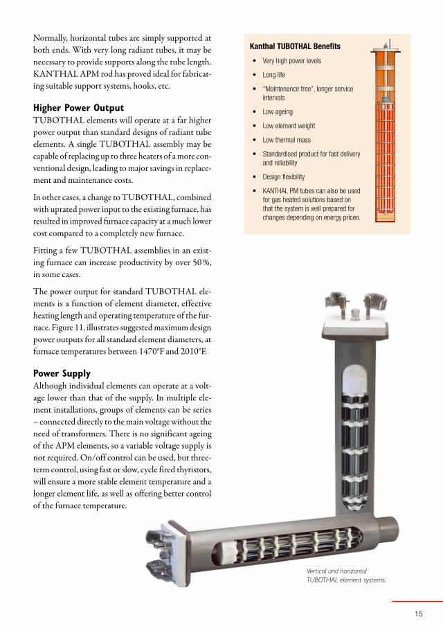
Kanthal TUBOTHAL Benefits
Very high power levels
Long life
“Maintenance free”, longer service intervals
Low ageing
Low element weight
Low thermal mass
Standardised product for fast delivery and reliability
Design flexibility
KANTHAL PM tubes can also be used for gas heated solutions based on that the system is well prepared for changes depending on energy prices.
•
•
•
•
•
•
•
•
•
Normally, horizontal tubes are simply supported at both ends. With very long radiant tubes, it may be necessary to provide supports along the tube length. KANTHAL APM rod has proved ideal for fabricat-ing suitable support systems, hooks, etc.
Higher Power OutputTUBOTHAL elements will operate at a far higher power output than standard designs of radiant tube elements. A single TUBOTHAL assembly may be capable of replacing up to three heaters of a more con-ventional design, leading to major savings in replace-ment and maintenance costs.
In other cases, a change to TUBOTHAL, combined with uprated power input to the existing furnace, has resulted in improved furnace capacity at a much lower cost compared to a completely new furnace.
Fitting a few TUBOTHAL assemblies in an exist-ing furnace can increase productivity by over 50 %, in some cases.
The power output for standard TUBOTHAL ele-ments is a function of element diameter, effective heating length and operating temperature of the fur-nace. Figure 11, illustrates suggested maximum design power outputs for all standard element diameters, at furnace temperatures between 1470°F and 2010°F.
Power SupplyAlthough individual elements can operate at a volt-age lower than that of the supply. In multiple ele-ment installations, groups of elements can be series – connected directly to the main voltage without the need of transformers. There is no significant ageing of the APM elements, so a variable voltage supply is not required. On/off control can be used, but three-term control, using fast or slow, cycle fired thyristors, will ensure a more stable element temperature and a longer element life, as well as offering better control of the furnace temperature.
Vertical and horizontal TUBOTHAL element systems.
1
KANTHALPMMaterial
High Loading PotentialAt a furnace temperature of 1830°F, the loading can be more than double that of NiCr and FeNiCr tubes. This allows more flexible furnace designs and con-version of existing heating systems to higher furnace power. Fewer tubes are needed for the same power rating.
Less MaintenanceThe oxide is non-spalling, hence no scaling and no impurities inside the tube to contaminate the heat-ing element or gas burner. No need for downtime to clean the tubes. No scaling on the outside and no contamination of the goods in the furnace.
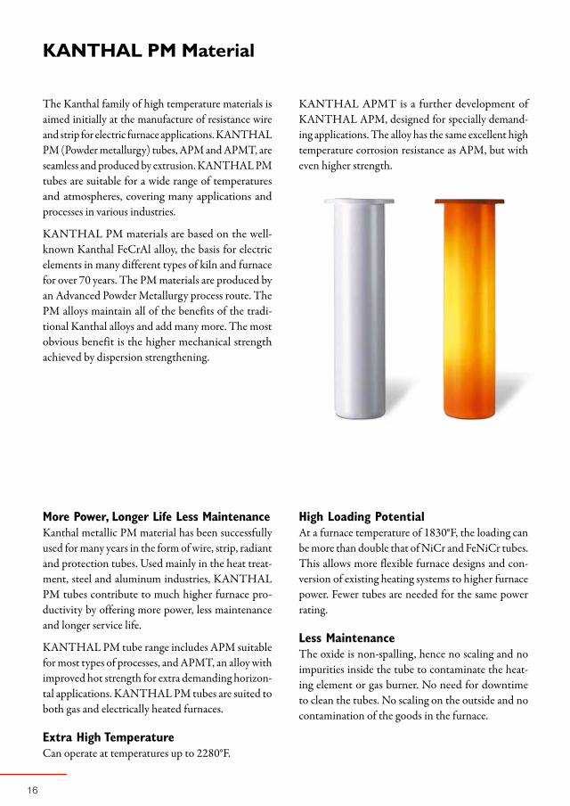
The Kanthal family of high temperature materials is aimed initially at the manufacture of resistance wire and strip for electric furnace applications. KANTHAL PM (Powder metallurgy) tubes, APM and APMT, are seamless and produced by extrusion. KANTHAL PM tubes are suitable for a wide range of temperatures and atmospheres, covering many applications and processes in various industries.
KANTHAL PM materials are based on the well-known Kanthal FeCrAl alloy, the basis for electric elements in many different types of kiln and furnace for over 70 years. The PM materials are produced by an Advanced Powder Metallurgy process route. The PM alloys maintain all of the benefits of the tradi-tional Kanthal alloys and add many more. The most obvious benefit is the higher mechanical strength achieved by dispersion strengthening.
More Power, Longer Life Less MaintenanceKanthal metallic PM material has been successfully used for many years in the form of wire, strip, radiant and protection tubes. Used mainly in the heat treat-ment, steel and aluminum industries, KANTHAL PM tubes contribute to much higher furnace pro-ductivity by offering more power, less maintenance and longer service life.
KANTHAL PM tube range includes APM suitable for most types of processes, and APMT, an alloy with improved hot strength for extra demanding horizon-tal applications. KANTHAL PM tubes are suited to both gas and electrically heated furnaces.
Extra High TemperatureCan operate at temperatures up to 2280°F.
KANTHAL APMT is a further development of KANTHAL APM, designed for specially demand-ing applications. The alloy has the same excellent high temperature corrosion resistance as APM, but with even higher strength.

17
Long LifeWhen heated, KANTHAL PM materials form an aluminum oxide (Al2O3) scale that protects the alloy from further corrosion and prolongs the service life, compared with ordinary NiCr or FeNiCr tubes.
No Tube CarburizationThe alumina oxide protects the alloy from carburiza-tion in high carbon-potential atmospheres.
KANTHAL PM materials withstand coking and metal dusting.
No Weak SpotsTubes are extruded, so there are no welded seams, eliminating a source of potential failure.
Excellent Form StabilityExcellent form stability even at elevated tempera-tures.
Low WeightKANTHAL PM tubes weigh less than equivalent NiCr and FeNiCr tubes of the same dimension.
Fig. 4 Comparison of APMT Tube vs. Fe-35Ni-25Cr (after 2300 h at 2010°F). The FeNiCr tube is severely contaminated with oxide flakes.
1
1470 1650 1830 2010 2190 ºF1560 1740 1920 2100
kW/ft²
1
2
3
4
5
6
7
8
9
GasFiredSystems
Straight Through TubesIn its simplest form, a radiant tube consists of a straight tube, with the burner fitted at one end and the exhaust chamber at the outlet. These straight through tubes, although simple and relatively inex-pensive, are inherently inefficient, as the temperature of the exhaust gases is significantly higher than the furnace temperature, and the majority of the energy of combustion is lost to the surroundings.
Radiant Tubes for Recuperative Systems – SER Burner SystemsThe majority of burners in use today are of a single ended design, where the burner and exhaust chamber are situated on the same side of the furnace. With these designs, the exhaust gases can be used to pre-heat the air required for combustion. This results in a major improvement in system efficiency, by exhausting only low temperature gases into the atmosphere. Common designs are U, W, and P shaped tubes, but these are gradually being replaced by less expensive and lighter single-ended recuperative burners, SER. With this
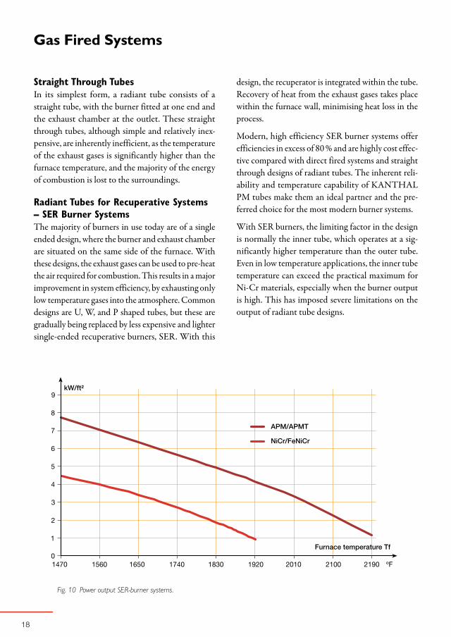
Fig. 10 Power output SER-burner systems.
design, the recuperator is integrated within the tube. Recovery of heat from the exhaust gases takes place within the furnace wall, minimising heat loss in the process.
Modern, high efficiency SER burner systems offer efficiencies in excess of 80 % and are highly cost effec-tive compared with direct fired systems and straight through designs of radiant tubes. The inherent reli-ability and temperature capability of KANTHAL PM tubes make them an ideal partner and the pre-ferred choice for the most modern burner systems.
With SER burners, the limiting factor in the design is normally the inner tube, which operates at a sig-nificantly higher temperature than the outer tube. Even in low temperature applications, the inner tube temperature can exceed the practical maximum for Ni-Cr materials, especially when the burner output is high. This has imposed severe limitations on the output of radiant tube designs.

1
KANTHAL PM radiant tubes however, are capable of far higher operating temperatures than NiCr. This has allowed burner manufacturers to exploit the higher outputs of modern designs to the full, dis-sipating the same power input in the furnace with fewer tubes, or uprating the input to existing systems (Figure 10). The potential benefits, in terms of pro-ductivity and installed costs, are immense and the use of KANTHAL PM materials has extended the temperature range of radiant tube assemblies.
Silicon Carbide Inner Tubes Silicon carbide can be combined with KANTHAL PM tubes in gas applications, where the tempera-ture is higher or the power loading is higher than metallic tubes can endure. SER burner systems that work at very high temperature or high loading can be designed with a ceramic flame tube (inner). The flame tube is the part in the system that works at the highest temperature, often 210–390°F warmer than the outer tube. As outer tubes,
Straight through
Vertical SER
Horizontal SER
KANTHAL PM tubes can work under tougher con-ditions than other metallic tubes and have better resis-tance to thermal shock than ceramic tubes. Flanges, end caps and support systems are much cheaper and easier to install for metallic systems com-pared to ceramic.


21
KANTHALAPM-TubesStandardProductRange
OD[in]
Wallthickness
[in]
WeightAPM
[lbs/ft]
WeightAPMT[lbs/ft]
Max.length
[ft]
APMstandard stock
APMTstandard stock
1.05 0.11 1.02 42.6 •
1.31 0.13 1.52 42.6 •
1.33 0.24 2.49 34.4 •
1.57 0.12 1.67 42.6 •
2.00 0.25 4.23 4.29 23.0 • •
2.38 0.15 3.31 26.2 •
2.52 0.16 3.60 3.65 23.0 • •
2.95 0.18 4.76 4.83 39.4 • •
3.27 0.20 5.85 5.93 39.4 • •
3.50 0.22 6.85 6.99 39.4 • •
3.94 0.20 7.12 7.26 37.7 • •
4.29 0.20 7.79 32.8 •
4.53 0.22 9.00 9.14 26.2 • •
5.04 0.22 10.08 39.4 •
5.75 0.24 12.57 31.2 •
6.06 0.24 13.30 13.51 26.2 • •
6.46 0.24 14.25 23.0 •
7.01 0.31 20.36 21.3 •
7.80 0.35 25.47 16.4 •
Tolerances
Tubes ≤ OD 1.97 in OD ± 1.5 %, min ± 0.030 in
Wall thickness ± 15 %, min ± 0.024 in
Straightness Max height of arc 0.12 in/39.37 in
Tubes > OD 1.97 in OD ± 1 %
Wall thickness ± 15 %
Straightness Max height of arc 0.12 in/39.37 in
PM tubes are also successfully used as muffles in sintering and mesh belt furnaces.

23
Dim. Resistance WeightB & S [Ω/ft] [lbs/1000 ft]
00 0.0064 317
0 0.0083 255
1 0.0104 202
2 0.0131 160
3 0.0166 127
4 0.0209 101
5 0.0264 79.8
6 0.0332 63.3
7 0.0419 50.2
8 0.0528 39.8
9 0.0666 31.6
10 0.0840 25.1
11 0.106 19.8
12 0.134 15.8
13 0.168 12.5
14 0.212 9.91
15 0.268 7.87
16 0.338 6.23
17 0.425 4.95
18 0.537 3.92
°F 68 210 390 570 750 930 1110 1290 1470 1650 1830 2010 2190 2370 2550
Ct 1.00 1.00 1.00 1.00 1.00 1.01 1.02 1.02 1.03 1.03 1.04 1.04 1.04 1.04 1.05
Width Thickness Resistance Weight[in] [in] [Ω/ft] [lbs/1000 ft]
1/2 0.04 0.0343 61.4
3/4 0.04 0.0228 92.2
1 0.04 0.0171 123
1/2 0.06 0.0228 92.2
3/4 0.06 0.0152 138
1 0.06 0.0114 184
1/2 0.08 0.0171 123
3/4 0.08 0.0114 184
1 0.08 0.0086 246
3/4 0.10 0.0091 230
1 0.10 0.0069 307
1 1/2 0.10 0.0046 461
1 0.12 0.0057 369
1 1/2 0.12 0.0038 553
1 3/4 0.12 0.0028 645
KANTHALA-1Wire Standard Stock Items. Strip Manufactured to Order.
Resistivity 872 Ω/cmf. Density 0.256 lb/in3. To obtain resistivity at working temperature, multiply by factor Ct in following table.
For minor dimensions please contact Kanthal directly. Contact information can be found on the back cover.
Strip (at 68°F)Wire (at 68°F)
24
°F 68 210 390 570 750 930 1110 1290 1470 1650 1830 2010 2190 2370 2550
Ct 1.00 1.00 1.00 1.00 1.00 1.01 1.02 1.02 1.03 1.03 1.04 1.04 1.04 1.04 1.05
Dim. Resistance WeightB & S [Ω/ft] [lbs/1000 ft]
8.25* 0.0083 255
6.00 0.0156 135
5.50 0.0186 113
5.00 0.0225 93.7
4.50 0.0278 75.9
4.25 0.0312 67.7
4.00 0.0352 60.0
3.50 0.0460 45.9
3.00 0.0626 33.8
2.50 0.0901 23.4
2.00 0.141 15.0
1.50 0.250 8.44
1.00 0.563 3.75
Width Thickness Resistance Weight[in] [in] [Ω/ft] [lbs/1000 ft]
1/2 0.04 0.0343 61.4
3/4 0.04 0.0228 92.2
1 0.04 0.0171 123
1/2 0.06 0.0228 92.2
3/4 0.06 0.0152 138
1 0.06 0.0114 184
1/2 0.08 0.0171 123
3/4 0.08 0.0114 184
1 0.08 0.0086 246
3/4 0.10 0.0091 230
1 0.10 0.0069 307
1 1/2 0.10 0.0046 461
1 0.12 0.0057 369
1 1/2 0.12 0.0038 553
1 3/4 0.12 0.0028 645
*B & S 0
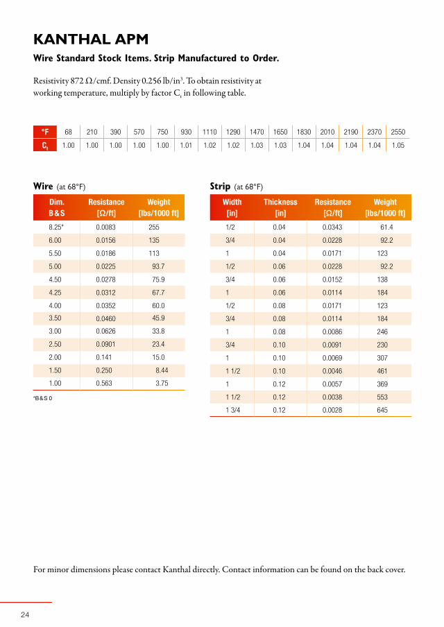
KANTHALAPMWire Standard Stock Items. Strip Manufactured to Order.
Resistivity 872 Ω/cmf. Density 0.256 lb/in3. To obtain resistivity at working temperature, multiply by factor Ct in following table.
Strip (at 68°F)Wire (at 68°F)
For minor dimensions please contact Kanthal directly. Contact information can be found on the back cover.
25
°F 68 210 390 570 750 930 1110 1290 1470 1650 1830 2010 2190 2370 2550
Ct 1.00 1.00 1.01 1.01 1.02 1.03 1.04 1.04 1.05 1.05 1.06 1.06 1.06 1.06 1.07
Dim. Resistance WeightB & S [Ω/ft] [lbs/1000 ft]
00 0.0063 324
0 0.0079 257
1 0.0100 204
2 0.0126 161
3 0.0159 128
4 0.0200 101
5 0.0253 80.5
6 0.0319 63.8
7 0.0402 50.6
8 0.0507 40.2
9 0.0639 31.8
10 0.0805 25.2
11 0.102 20.0
12 0.128 15.9
13 0.162 12.6
14 0.204 10.0
15 0.257 7.93
16 0.324 6.28
17 0.408 4.99
18 0.515 3.95
Width Thickness Resistance Weight[in] [in] [Ω/ft] [lbs/1000 ft]
1/2 0.04 0.0328 61.9
3/4 0.04 0.0219 92.2
1 0.04 0.0164 124
1/2 0.06 0.0219 92.9
3/4 0.06 0.0146 139
1 0.06 0.0109 186
1/2 0.08 0.0164 124
3/4 0.08 0.0109 186
1 0.08 0.0082 248
3/4 0.10 0.0088 232
1 0.10 0.0066 310
1 1/2 0.10 0.0044 464
1 0.12 0.0055 372
1 1/2 0.12 0.0036 558
1 3/4 0.12 0.0028 650
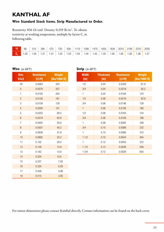
KANTHALAFWire Standard Stock Items. Strip Manufactured to Order.
Resistivity 836 Ω/cmf. Density 0.259 lb/in3. To obtain resistivity at working temperature, multiply by factor Ct in following table.
Strip (at 68°F)Wire (at 68°F)
For minor dimensions please contact Kanthal directly. Contact information can be found on the back cover.

2
°F 68 210 390 570 750 930 1110 1290 1470 1650 1830 2010 2190
Ct 1.00 1.01 1.02 1.03 1.04 1.04 1.04 1.04 1.04 1.04 1.05 1.06 1.07
Dim. Resistance WeightB & S [Ω/ft] [lbs/1000 ft]
00 0.00533 377
0 0.00621 298
1 0.00783 237
2 0.00988 188
3 0.0125 149
4 0.0157 118
5 0.0198 93.6
6 0.0250 74.2
7 0.0315 58.9
8 0.0397 46.7
9 0.0501 37.0
10 0.0630 29.4
11 0.0797 23.3
12 0.100 18.5
13 0.127 14.7
14 0.160 11.6
15 0.201 9.22
16 0.254 7.30
17 0.320 5.80
18 0.404 4.59
Width Thickness Resistance Weight[in] [in] [Ω/ft] [lbs/1000 ft]
1/2 0.04 0.0257 72
3/4 0.04 0.0172 178
1/2 0.6 0.0172 108
3/4 0.6 0.0114 162
3/4 0.8 0.0086 216
1 0.8 0.0064 288
1 1/4 0.8 0.0052 360
1 0.10 0.0052 360
1 1/2 0.10 0.0034 540
1 3/4 0.10 0.0029 630
1 0.125 0.0041 450
1 1/2 0.125 0.0028 675
1 3/4 0.125 0.0024 788
NIKROTHAL80Wire Standard Stock Items. Strip Manufactured to Order.
Resistivity 655 Ω/cmf. Density 0.300 lb/in3. To obtain resistivity at working temperature, multiply by factor Ct in following table.
Wire (at 68°F) Strip (at 68°F)
For minor dimensions please contact Kanthal directly. Contact information can be found on the back cover.
27
Dim. Resistance WeightB & S [Ω/ft] [lbs/1000 ft]
00 0.00533 368
0 0.00673 291
1 0.00848 231
2 0.0107 183
3 0.0135 145
4 0.0169 116
°F 68 210 390 570 750 930 1110 1290 1470 1650 1830 2010 2190
Ct 1.00 1.01 1.02 1.03 1.04 1.05 1.05 1.04 1.04 1.04 1.05 1.05 1.06
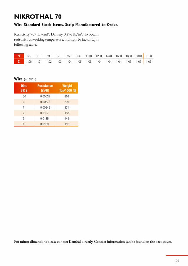
NIKROTHAL70Wire Standard Stock Items. Strip Manufactured to Order.
Resistivity 709 Ω/cmf1. Density 0.296 lb/in3. To obtain resistivity at working temperature, multiply by factor Ct in following table.
Wire (at 68°F)
For minor dimensions please contact Kanthal directly. Contact information can be found on the back cover.
2
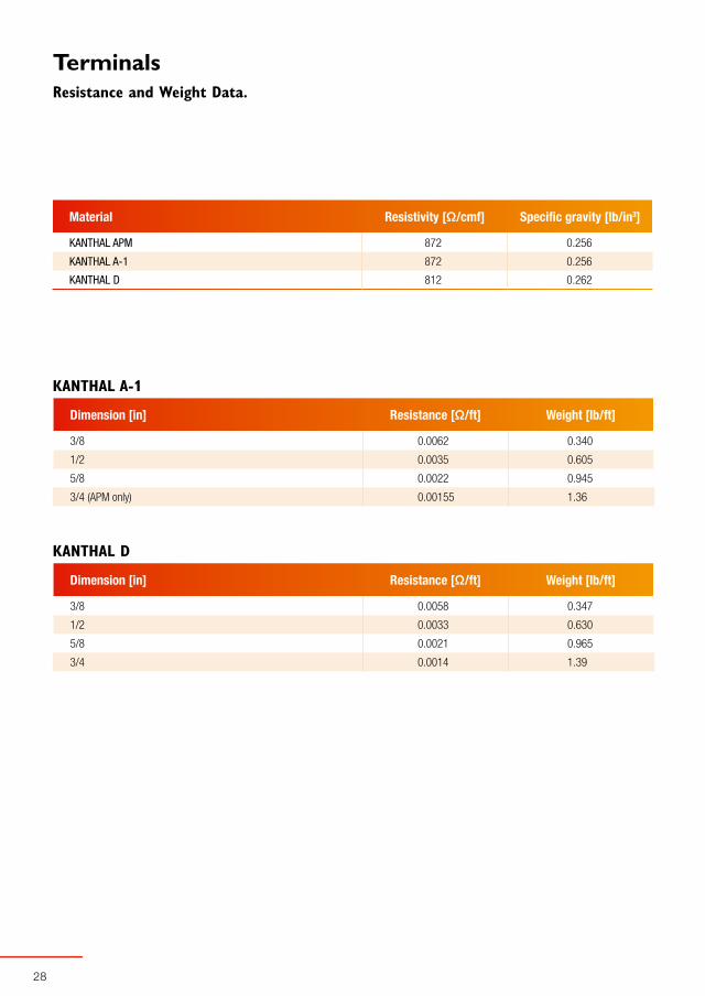
Material Resistivity [Ω/cmf] Specific gravity [lb/in3]
KANTHAL APM 872 0.256
KANTHAL A-1 872 0.256
KANTHAL D 812 0.262
Dimension [in] Resistance [Ω/ft] Weight [lb/ft]
3/8 0.0062 0.340
1/2 0.0035 0.605
5/8 0.0022 0.945
3/4 (APM only) 0.00155 1.36
Dimension [in] Resistance [Ω/ft] Weight [lb/ft]
3/8 0.0058 0.347
1/2 0.0033 0.630
5/8 0.0021 0.965
3/4 0.0014 1.39
TerminalsResistance and Weight Data.
KANTHAL A-1
KANTHAL D

30
Kanthal – a World-Renowned Name Within the Field of Electric Heating Since the early thirties, Kanthal has developed market leading, electric resistance alloy products and materials.
Our R&D efforts have always been directed at improving our materials to function fully at ever higher tempera-tures.
The centre for production, product development and metallurgy is in Hallstahammar, Sweden, whilst sales and production finishing plants are located around the world, close to our customers and operated through our subsidiaries and local representatives.
Kanthal – a Member of the Sandvik Group The Sandvik Group is a global high technology enterprise with 41,700 employees and annual sales of approximately SEK 72 billion. Sandvik’s operations are concentrated on its three core businesses of Sandvik Tooling, Sandvik Mining and Construction and Sandvik Materials Technology. Sandvik spends about 4 percent of is turnover on research and development.
Kanthal is a part of the business area Sandvik Materials Technology – a world-leading manufacturer of high-value-added products in advanced stainless steels, special alloys, metallic and ceramic resistance materials, as well as process plants and sorting systems.
As a member of the Sandvik Group, Kanthal has got full access to world-class competence within materials and process technology, as well as Sandvik Materials Technology’s R&D-center in Sweden, which is one of the most distinguished in the world. Through Sandvik’s global sales organisation Kanthal is represented in 130 countries.
31
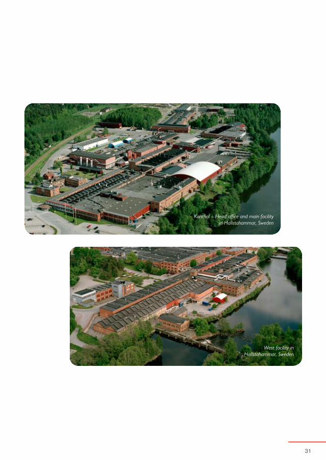
West facility in Hallstahammar, Sweden
Kanthal – Head office and main facility in Hallstahammar, Sweden
1-A
-5B
-3 U
S
11-0
7-30
00
Kan
thal
AB
, M
arke
t C
omm
unic
atio
ns
PR
IMA
tryc
k, H
alls
taha
mm
ar
Kanthal – a Sandvik brand
Kanthal Corporation, 11 Wooster Street, P.O. Box 21, Bethel, CT 001-021, USAPhone 203-744 1440 Fax 203-74 222 www.kanthal.com
KanthalSalesandServiceAllOvertheWorld
EUROPEBulgariaKanthal Representative OfficeSOFIAPhone +359 2 870 4297Fax +359 2 297 14813
DenmarkKanthal ABBRØNDBYPhone +45 4346 5270Fax +45 4346 5271
EnglandKanthal Ltd.STOKE-ON-TRENTPhone +44 1782 224 800Fax +44 1782 224 820
FinlandSandvik Mining and Construction Oy - KanthalVANTAAPhone +358 20 544 121Fax +358 20 544 5199
FranceSANDVIK SAS - Division KanthalCOLOMBESPhone +33 1 4786 5660Fax +33 1 4781 5661
GermanyKanthal ZN der Sandvik GmbHMOERFELDEN-WALLDORFPhone +49 6105 40010Fax +49 6105 400188
ItalySandvik Italia S.p.A Divisione KanthalMILANOPhone +39 02 307 051Fax +39 02 300 98605
NorwayKanthal ABLILLESTRØMPhone +47 6484 3560Fax +47 6484 3565
PolandSandvik Polska Sp. z.o.o. - KanthalWARSAWPhone +48 22 647 3880Fax +48 22 843 0588
RussiaOAO Sandvik - MKTCMOSCOWPhone +7 495 689 8385Fax +7 495 745 8720
ScotlandKanthal Ltd.PERTHPhone +44 1738 493 300Fax +44 1738 493 301
SpainSandvik Española S.A.Kanthal DivisionMARTORELLESPhone +34 93 571 7540Fax +34 93 571 7586
SwedenKanthal ABHALLSTAHAMMARPhone +46 220 21000Fax +46 220 16350
TurkeySandvik Endüstriyel Mamüller San. ve Tic. A.SKARTAL- ISTANBULPhone +90 216 453 0700Fax +90 216 453 0707
NORTH&SOUTHAMERICAUnitedStatesKanthal CorporationBETHEL, CTPhone +1 203 744 1440Fax +1 203 748 2229
Kanthal Heating SystemsAMHERST, NYPhone +1 716 691 4010Fax +1 716 691 7850
Kanthal Palm Coast PALM COAST, FLPhone +1 386 445 2000Fax +1 386 446 2244
MRL Industries Inc.SONORA, CAPhone +1 209 533 1990Fax +1 209 533 4079
BrazilSandvik do Brasil S.A. - KanthalVINHEDOPhone +55 19 3826 7400Fax +55 19 3826 7416
ASIAHongKongKanthal Electroheat HK Ltd.KOWLOONPhone +852 2735 0933Fax +852 2735 7238
IndiaSandvik Asia Ltd. - KanthalTAMIL NADUPhone +91 4344 275 490Fax +91 4344 277 244
ChinaKanthal China (Shanghai office)c/o Sandvik Int. Trading Co., Ltd.SHANGHAIPhone +86 21 5869 8969Fax +86 21 5869 6155
JapanSandvik KK - Kanthal DivisionTOKYOPhone +81 3 6420 1070Fax +81 3 6420 1071
SingaporeKanthal Electroheat (SEA) Pte. Ltd.SINGAPOREPhone +65 6 477 3742Fax +65 6 477 3744
SouthKoreaKanthal in Koreac/o Sandvik Korea Ltd.SEOULPhone +82 2 761 0432Fax +82 2 761 0435
OCEANIAAustraliaSandvik Australia Kanthal DivisionDANDENONGPhone +61 3 9238 7216Fax +61 3 9238 7165
NewZealandSandvik New Zealand Ltd.AUCKLANDPhone +64 9 2735 888Fax +64 9 2735 899
AFRICASouthAfricaSandvik Ltd. Kanthal DivisionEAST RANDPhone +27 11 570 9618Fax +27 11 570 9693