residual stress distribution in an al,o,-ni …/67531/metadc670552/m2/1/high...neutron diffraction...
TRANSCRIPT

RESIDUAL STRESS DISTRIBUTION IN AN Al,O,-Ni JOINT BONDED WITH A COMPOSITE LAYER
X.-L. Wang'), B. H. Rabid), R. L. Williamson2', H. A. Bruck2), and T. R. Watkins') ''Oak Ridge National Laboratory, Oak Ridge, TN 37831-6064 ''Idaho National Engineering Laboratory, Idaho Falls, ID 834 15-22 18
ABSTRACT
Neutron diffraction was used to investigate the residual stress distribution in an axisymmetric A120,-Ni joint bonded with a 40 v01%A120,-60 volBNi composite layer. A series of measurements was taken along the axis of symmetry through the Al,O, and composite layers. It is shown that after taking into account the finite neutron diffraction sampling volume, both the trends and peak values of the experimentally determined strain distribution were in excellent agreement with calculations of a simple finite element model, w h m the rule-of-mixtures approach was used to describe the constitutive behavior of the composite interlayer. In particular, the predicted steep strain gradient near the interface was confmed by the experimental data.
INTRODUCTION
High-strengh ceramic-metal joints are being developed for use in a great variety of industrial applications, ranging from structural components in heat engines to coatings in electronic devices. However, upon cooling from the fabrication temperature, residual smsses develop due to the thermal expansion mismatch between the metal and ceramic components. Moreover, although no experimental evidence has been reported, a tensile stress concentration was repeatedly predicted by various finite element models to occur near the edges of the ceramic component close to the interface [l-21. In some cases, these residual stresses exceed the bond strength and promote mechanical failure along the ceramic-metal interface. In cases when the bond is strong, the residual stresses tend to cause fracture in the ceramic. Earlier experimental studies [3-61, principally by X-ray and neutron diffraction, have shown that the residual stress distribution in directly bonded ceramic-metal joints is reasonably understood within the frame work of elasto-plastic finite element calculations.
One approach to reduce the residual stress in ceramic-metal joints is through the use of functionally graded materials, where materials properties including thermal expansion vary continuously from one end to the other. A variety of analytical and numerical models have been developed to understand and optimize the residual stress state in these materials. Due to the complexity of the microstructures involved and the associated difficulties in describing the constitutive behavior of the composite layers, simplifying approximations, such as rule-of- mixtures, are typically used. Critical needs, therefore, exist for experimental verifrcation of these models before they can be used with confidence for design purposes. In this paper, we report a neutron diffraction determination of the residual stress distribution in a prototype functionally graded material and a comparison of the experimental data with the results of a finite element analysis [2]. The measurements focus on the vicinity of the interface between the ceramic and composite layers where a steep strain gradient has been predicted.
EXPERIMENTAL DETAILS MA The specimen, in the shape of a rod, is a three-layer material, consisting of an Al2O3 layer, a
Ni layer, and a 40 vol% Al2O3-60 vol% Ni composite interlayer. It was fabricated using powder processing techniques [7], followed by controlled cooling to room temperature. The specimen

. thus fabricated exhibits sharp interfaces between layers. Micrographs taken from the composite layer indicate a uniform microstructure with a rather continuous AI203 phase. A schematic of the specimen, along with the dimensions, is shown in Fig. 1.
ORNL-DWG 95M-6382
A: AI203
8: 60% Ni - 40% AIzO,
0 5 d MILLIMETERS
C: Ni
Fig. 1 Schematic of the specimen used for neutron diffraction measurements.
The neutron diffraction measurements were conducted at the High Flux Isotope Reactor of Oak Ridge National Laboratory using a triple-axis spectrometer operated in the diffractometer mode. A Be (1 1 0) reflection was used as the monochromator. The take-off angle for the monochromator was 90’ and the incident neutron wavelength was 1.615 8, To facilitate fast data collection, a position sensitive detector was mounted at the analyzer position of the spectrometer. Slits of dimensions 0 . 8 ~ 4 mm2 and 0.8~30 mm2 were inserted before and after the specimen, which together defined a sampling volume of approximately 2.6 mm3. Radial and axial strain (E, and distributions were investigated in this study. For each strain component, a series of measurements was taken along the specimen axis of symmetry through the M,O, and composite layers. For the purpose of illustration, the specimen orientation for the measurement of E, is shown in Fig. 2.
In order to observe the predicted steep strain gradient near the interface, high spatial resolution is essential. In principle, this would require a small sampling volume at the expense of reduced scattering intensity. Fortunately, earlier neutron diffraction measurements and finite element modeling studies have demonstrated that in cylindrical ceramic-metal joint systems, strains along major axes (E*, &, and Ee) are almost constant over half of the radius. This has permitted the use of narrow but tall slits to obtain reasonable scattering intensity without sacrificing the spatial resolution in the desirable directions, as illustrated in Fig. 2. To further improve the ability of detecting the predicted strain gradient, the specimen was over-stepped
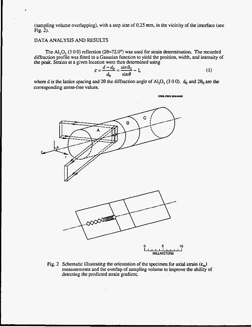
(sampling volume overlapping), with a step size of 0.25 mm, in the vicinity of the interface (see Fig. 2).
DATA ANALYSIS AND RESULTS
The A120, (3 0 0) reflection (28-72.0') was used for strain determination. The recorded diffraction profile was fitted to a Gaussian function to yield the position, width, and intensity of the peak. Strains at a given location were then determined using
I d - d , sin80 do sin8
&=-=--
where d is the lattice spacing and 28 the diffraction angle of 40, (3 0 0). 6 and 20, are the corresponding stress-free values.
I.
0 & MILLIMETERS
Fig. 2 Schematic illustrating the orientation of the specimen for axial strain (a measurements and the overlap of sampling volume to improve the ability of detecting the predicted strain gradient.

In general, strains measured with diffraction methods are a superposition of macro- and microstrains. Since in this study we were solely concerned with the macrostrain distribution resulting from the thermal expansion mismatch between bonded dissimilar materials, the data points farthest from the interface were chosen to be zero. In this way, effects of any microstrains due to the thermal expansion anisotropy within the single phase A120, were removed. However, data in the composite layer stili contain a contribution of microstrains from the thermal expansion mismatch between A120, and Ni phases, which is expected to be compressive and of the order of lo4.
Fig. 3 shows the experimentally determined E, and E, along the axis of symmetry. The error bars are estimated standard deviations from least-squares fitting of the recorded diffraction profdes, which in this experiment were dominated by the unfavorable scattering intensity due to the small sampling volume used.
Q 2 X
-7 +- i- f Jr f 4
2
0
-2
-4
0 2 4 6 8
t , ’ . , . . rn A 1 -
d
d Interface
-
J : Interlayer
d 10 12 14
Position from A1,03 End (mm)
Fig. 3 Experimentally determined strain distribution and the results of finite element modeling along the axis of symmetry for (a) E, and (b) G. The symbols are experimental data; the solid curves are fmite element results which have been averaged to take into account the finite neutron diffraction sampling volume.

Within the experimental precision, the experimental data provided evidence of a sharp strain gradient through the interface. Overall, the magnitudes of the measured strains are quite small, on the order of lo4. In the A1203 layer, E, becomes increasingly compressive as the interface is approached. The maximum compressive strain is located on the Al,03 side adjacent to the interface. Upon entering the composite layer, E, changes from compressive to tensile at approximately 1 mm from the interface. Given the error bars, the experimental data also suggest that reaches a tensile maximum in the middle of the composite layer. G, on the other hand, shows a quite different axial dependence. It is mostly compressive in the M,O, layer, becoming tensile only when the interface is approached. Measurements of E, across the interface were not attempted because in this measurement geometry, an artificial peak shift was anticipated when the sampling volume was partially buried in the Al,O, layer [8]. This artifact leads to an apparent strain and adds ambiguity to the determination of G.
COMPARISON WITH FINITE ELEMENT MODELING
The finite element model described in Ref. [Z] was utilized to evaluate the residual stress and strain distributions for the specimen measured with neutron diffraction. Spatially uniform cooling and perfect bonding at materials interface were assumed. Because the specimen remains axisymmetric during cooling, the model was reduced to two-dimensional computation. Fine meshing was employed in the vicinity of interfaces and the radial free surface, due to the expected large stress and strain gradients in these regions. All materials were assumed to be isotropic. The A120, was required to remain elastic, while plasticity was allowed in the Ni and composite layers. Creep behaviors were not considered in the present model, i.e., materials response was assumed to be independent of time. Mechanical and thermophysical properties for the composite layers were assigned using a modified rule-of-mixture approach [9]. Additional information concerning the general modeling approach, materials properties, and particularly the rule-of-mixture formation, can be found in Ref. [2]. Numerical solutions were obtained using the ABAQUS computer program [lo].
For comparison, the calculated strain values along the axis of symmetry are also plotted in Fig. 3 (solid lines). Note that here the numerical results have been averaged to take into account the finite neutron diffraction sampling volume. As can be seen, the calculations and experimental data are in excellent agreement in both the trends and peak values. In particular, the predicted steep strain gradient near the interface was confirmed by the experimental data.
As the finite element results were compared with the experimental data, it became clear that the fmite neutron diffraction sampling volume had to be considered in order to seek quantitative agreement. In an initial comparison, the numerical results were simply plotted for the column of elements adjacent to the axis of symmetry. Ln this case, the magnitudes of calculated strains were significantly higher than the experimental values, particularly in the vicinity of the interface Only when the finite element results were averaged over the neutron diffraction sampling volume was quantitative agreement realized.
DISCUSS ION
The present experiment demonstrates that with appropriate experimental arrangement, strain changes over the range of 1-2 mm can be spatially resolved by neutron diffraction. This level of spatial resolution is required for mapping the residual stress distribution near the interface of ceramic-metal joint structures, as was evidenced in this study. Because neutrons are highly penetrating in most materials, the measurements are non-destructive and, in general, no special specimen preparation is required.
As stated earlier, the specimen under study is a prototype functionally graded structure and the experiment was designed to verify the constitutive relationship used for predicting the

t
residual stress distribution. The neutron diffraction data show that the modified rule-of-mixtures approach [9] provides an adequate description of the residual strain distribution along the axis of symmetry. This gives confidence to use the model to address key issues in the design of ceramic-metal joints. For example, controlling of the tensile stress concentration, located near the edges of the ceramic component close to the interface, is highly desirable. There, the plasticity in the composite layers is expected to play an important role. Also, the creep behavior in the metal as well as the composite layers may have to be considered. An experimental investigation is currently in progress to determine the mechanical and thermophysical properties of the composite materials containing various amounts of Al,O, to further verify the accuracy of the rule-of-mixtures approach used in the model.
Ni and A120, layer, the peak stress values near the interface are reduced. Although the calculations are made for rod-shaped specimen, the model can be readily adapted to calculate the residual stresses in disk-shaped specimens [3] and perhaps in laminated materials as well so long as there is no atomic diffusion between layers. Because of the limited intensity, the present mapping system does not yet have sufficient spatial resolution to determine the distribution of residual stresses in thin laminated materials. However, work is underway to improve the instrument so that neutron diffraction data can be collected with a much smaller sampling volume (hence higher spatial resolution), which will enable direct determination of the residual stress distribution in laminated materials.
Using the present model, it can be shown that by inserting a composite layer between the
ACKNOWLEDGMENTS
This research was sponsored in part by the U. S. Department of Energy, Assistant Secretary for Energy Efficiency and Renewable Energy, Office of Transportation Technologies, as part of the High Temperature Materials Laboratory User Program. Partial support was also provided by U. S. Department of Energy, Office of Energy Research, Office of Basic Energy Sciences, Division of Materials Sciences. Oak Ridge National Laboratory is managed by Lockheed Martin Energy Research Corp. for the U.S. Department of Energy under contract number DE-ACO5- 960R22464.
REFERENCES
P. 0. Charreyron, N. J. Bylina, and J. G. Hannoosh, in Fracture Mechanics of Ceramics Vol. 8 (Plenum Press, New York, 1986) p. 225; P. 0. Charreyron, D. 0. Patten, and B. J. Miller, Ceram. Eng. Sci. Proc., 10, 1801 (1989). R. L. Williamson, B. H. Rabin, and J. T. Drake, J. Appl. Phys., 74,1310-20 (1993). X.-L. Wang, C. R. Hubbard, S. Spooner, S. A. David, B. H. Rabin, and R. L. Williamson, Mat. Sci. Eng. (in press).
Edited by C. S. Barret et al. (Plenum Press, New York, 1990) p. 353. 0. T. Iancu, D. Munz, B. Eigenmann, B. Scholtes, and E. Macherauch, J. Am Ceram Soc.,
L. Pintschovius, N. Pyka, R. Kubmaul, D. Munz, B. Eigenmann, and B. Scholtes, Mat. Sci. Eng., A177,55 (1994). €3. H. Rabin and R. J. Heaps, Cerum Trans., 34,173 (1993). S. Spooner and X.-L. Wang, unpublished. Tamura, Y. Tomota, and H. Ozawa, in Proceed ines of the Third International Conference P n Strength of Metals and A 11 ov (Institute of Metal and Iron and Steel Institute, London, 1973) p. 611. ABAQUS, Habbitt, Karlssan, and Sorensen, Inc., Pawtucket, Rhode island (193).
K. Masanori, M. Sato, I. Ihara, and A. Saito, in Adv
73,1144 (1990).
- sis, VOl. 33,