residual stress analysis of laser-drilled thermal barrier
TRANSCRIPT
HAL Id: hal-01174675https://hal.archives-ouvertes.fr/hal-01174675v2
Submitted on 26 Aug 2015
HAL is a multi-disciplinary open accessarchive for the deposit and dissemination of sci-entific research documents, whether they are pub-lished or not. The documents may come fromteaching and research institutions in France orabroad, or from public or private research centers.
L’archive ouverte pluridisciplinaire HAL, estdestinée au dépôt et à la diffusion de documentsscientifiques de niveau recherche, publiés ou non,émanant des établissements d’enseignement et derecherche français ou étrangers, des laboratoirespublics ou privés.
Residual Stress Analysis of Laser-Drilled ThermalBarrier Coatings Involving Various Bond Coats
Caroline Guinard, Guillaume Montay, Vincent Guipont, Michel Jeandin,Jérémie Girardot, Matthieu Schneider
To cite this version:Caroline Guinard, Guillaume Montay, Vincent Guipont, Michel Jeandin, Jérémie Girardot, etal.. Residual Stress Analysis of Laser-Drilled Thermal Barrier Coatings Involving Various BondCoats. Journal of Thermal Spray Technology, ASM International/Springer, 2014, 24, pp.252-262.�10.1007/s11666-014-0185-z�. �hal-01174675v2�
Residual Stress Analysis of Laser-DrilledThermal Barrier Coatings Involving Various
Bond CoatsC. Guinard, G. Montay, V. Guipont, M. Jeandin, J. Girardot, and M. Schneider
The gas turbine combustion chamber of aero-engines requires a thermal barrier coating (TBC) bythermal spraying. Further heat protection is achieved by laser drilling of cooling holes. The residualstresses play an important role in the mechanical behaviour of TBC. It could also affect the TBCresponse to delamination during laser drilling. In this work, studies of the cracking behaviour after laserdrilling and residual stress distribution have been achieved for different bond coats by plasma spray orcold spray. From interface crack length measured pulse-by-pulse after laser percussion drilling at 20!angle, the role of the various bond coats on crack initiation and propagation are investigated. It is shownthat the bond coat drastically influences the cracking behaviour. The residual stresses profiles were alsodetermined by the incremental hole-drilling method involving speckle interferometry. An originalmethod was also developed to measure the residual stress profiles around a pre-drilled zone with a laserbeam at 90!. The results are discussed to highlight the influence of TBCs interfaces on the resultingresidual stresses distribution before laser drilling, and also to investigate the modification around the holeafter laser drilling. It is shown that laser drilling could affect the residual stress state.
Keywords atmospheric plasma spray (APS), cold spray,functionally graded coatings, hole-drilling meth-od, laser drilling, residual stress determination,thermal barrier coatings (TBCs)
1. Introduction
The combustion chambers of gas turbines for aero-engines are protected by a thermal barrier coating (TBC).It consists of a metallic MCrAlY (M: Ni, Co, …) bond coat(that also acts as an oxidation resistant layer) and aceramic top coat, typically yttria-stabilized zirconia (YSZ)by plasma spraying. The porous ceramic top coat fulfils thecrucial function of insulating the metallic wall from thehigh temperature of combustion gases. In order to preventthe overheating of the component and achieve furtherheat protection, numerous cooling holes are drilled
throughout the chamber wall. Such holes enable a pro-tective air film that comes from the external side and flowsalong the internal face of the TBC-coated chamber.Combined with the porous ceramic, these holes drasticallyimprove the component durability and service life and alsocontribute to achieving a higher efficiency and a betterperformance of the turbine. In the manufacture and repairindustry of combustion chambers, laser drilling has be-come the conventional method because it is possible toprecisely operate cooling holes by machining the ceramicand metallic layers simultaneously (Ref 1, 2). There aretwo different drilling methods: laser percussion or lasertrepan. The more attractive mode from an industrial pointof view is pulsed laser percussion drilling because severallaser pulses are repeated with the same beam alignmentmaking this drilling mode faster. The percussion modealso allows smaller diameters for holes with a typical rangeof about 500 lm. Moreover, an acute drilling angle isnecessary to maximize the cooling effect of the air film.Indeed, highly inclined holes limit the turbulence of thegas flow around the air inlet zone and therefore betterprevent the formation of hot points due to hot gas stag-nation. With pulsed laser drilling, macro-cracks along theinterfaces can be observed after the hole has been ma-chined. Unfortunately, by selecting high angles of inci-dence (typically <30!), the ceramic top coat is moresensitive to delamination at the leading edge zone ifcompared to the normal incidence (Ref 3–5). The dela-minated area could lead to the spallation of the ceramictop coat in service and direct exposure of the metal to thehot gases. Moreover, from such a scenario, it is also to befeared that the ejected spall debris might impact and
C. Guinard, V. Guipont, and M. Jeandin, MINES ParisTech, PSL- Research University, MAT - Centre des materiaux, CNRSUMR 7633, BP 87, 91003 Evry, France; G. Montay, Universite deTechnologie de Troyes, ICD/LASMIS, 12 Rue Marie Curie, CS42060, 10004 Troyes, France; and J. Girardot andM. Schneider, Arts et Metiers ParisTech, PIMM, 151Boulevard de l!Hopital, 75013 Paris, France. Contact e-mail:[email protected].
damage downstream rotating parts. Therefore, the limi-tation of the pre-existing interfacial crack due to acuteangle laser drilling is a key issue for the manufacture orthe repair of TBC-coated combustion chambers withmulti-hole patterns machined by laser drilling. Most of thework devoted to laser-drilled TBC are investigating therole of laser parameters (pulse energy, shape or frequency,drilling angle) or induced mechanical effects (ejected melt,assist gas, etc.) that could affect the area of the detri-mental crack generated at the top coat/bond coat (TC/BC)interface or the bond coat/substrate (BC/S) interface (Ref6, 7). In addition, materials characteristics like composi-tion, density, and thickness might have a role in the holegeometry and any cracking (Ref 2, 4).
In this work, we investigated the role of differentmaterials and spraying processes used for bond coats inregard to interfacial cracks. The methodology was toachieve interrupted laser-drilling experiments with anacute drilling angle (20!). The purpose was to assess thecrack initiation and propagation in cases of a "severe!drilling condition for various bond coats. From theseexperiments, we then focussed on the residual stressanalysis of these various TBCs before and after laserdrilling around the machined area using the incrementalhole-drilling method involving conventional mechanicalmilling (Ref 8, 9). The goal was to bring out a discussionabout the role of residual stresses generated during thedeposition process and further modified by the laser-dril-ling process on crack generation. For the measurement ofresidual stress profiles around a laser-drilled hole, an ori-ginal method was developed involving specific TBCspecimens with a pre-drilled hole using a normal incidencefor the laser. The residual stress profiles were then com-pared between bulk and pre-drilled specimens for thevarious bond coats. The incremental hole was operatedconcentrically with a larger diameter to allow step-by-stepremoval of the material around a laser pre-drilled hole.
2. Materials and Methods
2.1 TBC Samples with Various Bond Coats
Three types of TBC bond coat were prepared: two ofthem were obtained by plasma spraying with a F100-Con-nex torch (Sulzer Metco, Wohlen, Switzerland) and thethird one was processed by cold spray using a KINETICS#
3000-M System (CGT, Ampfing, Germany). The first typeof plasma TBC was similar to conventional industrial plas-ma TBC, involving a !90 +106 lm NiCrAlY powder(Amdry 962; Sulzer Metco, Westbury, NY, USA) and a!125 +11 lm yttria stabilized zirconia powder (204NS;Sulzer Metco). The second type of plasma TBC was con-tinuously graded by increasing the YSZ powder feed ratewhile the NiCrAlY powder feed rate was simultaneouslydecreased during spraying the TBC coupon. The third typeof TBC was obtained by combining a cold-sprayed bondcoat with !38 +5.5 lm CoNiCrAlY powder (Amdry 9951;Sulzer Metco) to a plasma-sprayed YSZ top coat. Usinghelium as a processing gas, the fine CoNiCrAlY powder was
preferred to the coarse NiCrAlY powder to achieve adenser and more adhesive coating by cold spraying. Themain spraying parameters are summarized in Table 1. Forplasma, plasma-graded and cold-spray bond coats, all theceramic top coats were achieved with the same plasmaparameters. Cobalt base Haynes# 188 alloy plates (dimen-sions 150 9 40 mm2) were used as substrates. The plateswere roughened (Ra = 2.8 lm) by grit-blasting with a 250-lm corundum grit prior to coating operations (ALTISURF500; ALTIMET, Annecy, France). All substrates had 2 mmthickness except for the plasma-graded bond coat for whicha thinner substrate of 1.6 mm was selected. No significantmacroscopic deformation was observed on all coated platesafter spraying the whole TBC.
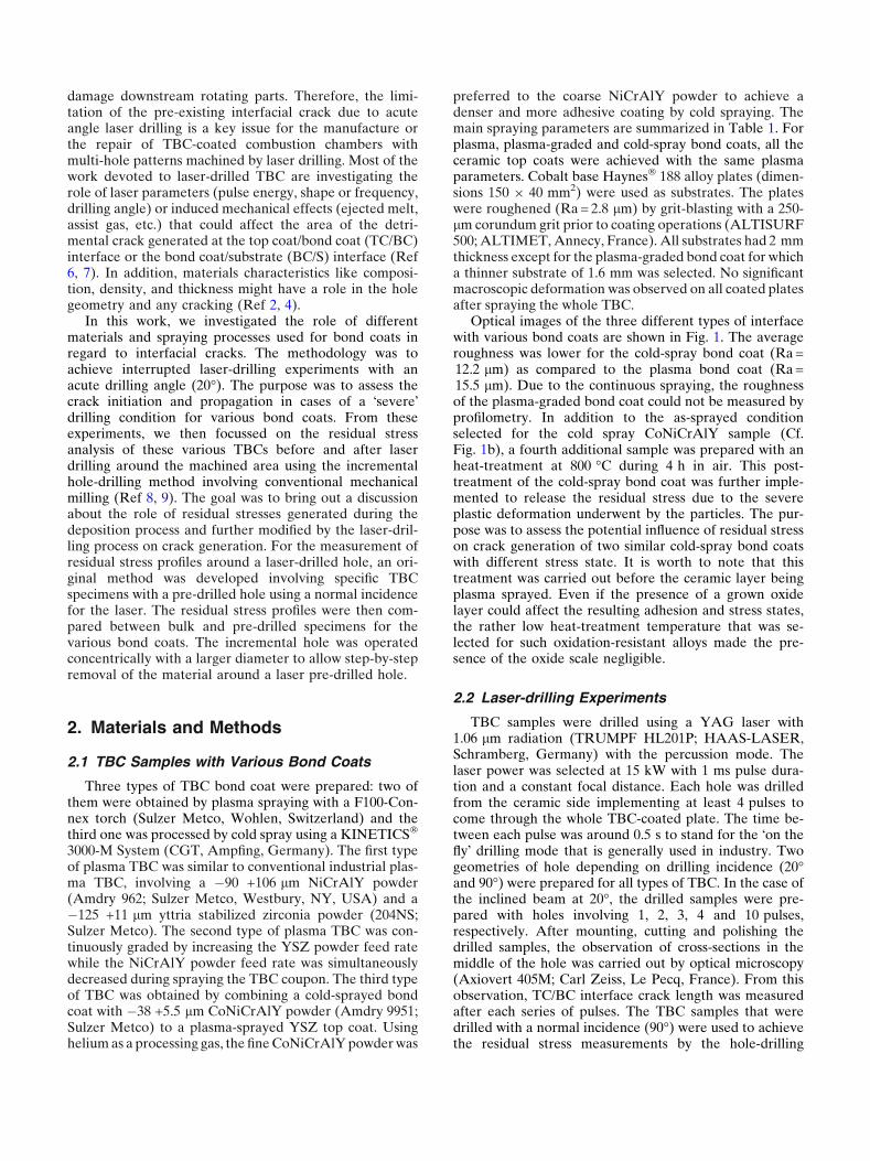
Optical images of the three different types of interfacewith various bond coats are shown in Fig. 1. The averageroughness was lower for the cold-spray bond coat (Ra =12.2 lm) as compared to the plasma bond coat (Ra =15.5 lm). Due to the continuous spraying, the roughnessof the plasma-graded bond coat could not be measured byprofilometry. In addition to the as-sprayed conditionselected for the cold spray CoNiCrAlY sample (Cf.Fig. 1b), a fourth additional sample was prepared with anheat-treatment at 800 !C during 4 h in air. This post-treatment of the cold-spray bond coat was further imple-mented to release the residual stress due to the severeplastic deformation underwent by the particles. The pur-pose was to assess the potential influence of residual stresson crack generation of two similar cold-spray bond coatswith different stress state. It is worth to note that thistreatment was carried out before the ceramic layer beingplasma sprayed. Even if the presence of a grown oxidelayer could affect the resulting adhesion and stress states,the rather low heat-treatment temperature that was se-lected for such oxidation-resistant alloys made the pre-sence of the oxide scale negligible.
2.2 Laser-drilling Experiments
TBC samples were drilled using a YAG laser with1.06 lm radiation (TRUMPF HL201P; HAAS-LASER,Schramberg, Germany) with the percussion mode. Thelaser power was selected at 15 kW with 1 ms pulse dura-tion and a constant focal distance. Each hole was drilledfrom the ceramic side implementing at least 4 pulses tocome through the whole TBC-coated plate. The time be-tween each pulse was around 0.5 s to stand for the "on thefly! drilling mode that is generally used in industry. Twogeometries of hole depending on drilling incidence (20!and 90!) were prepared for all types of TBC. In the case ofthe inclined beam at 20!, the drilled samples were pre-pared with holes involving 1, 2, 3, 4 and 10 pulses,respectively. After mounting, cutting and polishing thedrilled samples, the observation of cross-sections in themiddle of the hole was carried out by optical microscopy(Axiovert 405M; Carl Zeiss, Le Pecq, France). From thisobservation, TC/BC interface crack length was measuredafter each series of pulses. The TBC samples that weredrilled with a normal incidence (90!) were used to achievethe residual stress measurements by the hole-drilling
method involving mechanical milling. The through-holewith the laser beam at 90! was obtained after 2 pulsesonly, but 4 pulses were needed to achieve a more regularshape with an average diameter of 500 lm.
2.3 Residual Stress Analysis
The hole-drilling method is a semi-destructive relaxa-tion method to determine the residual stress depth profilein a structure (Ref 8). When a blind-hole is machined in a
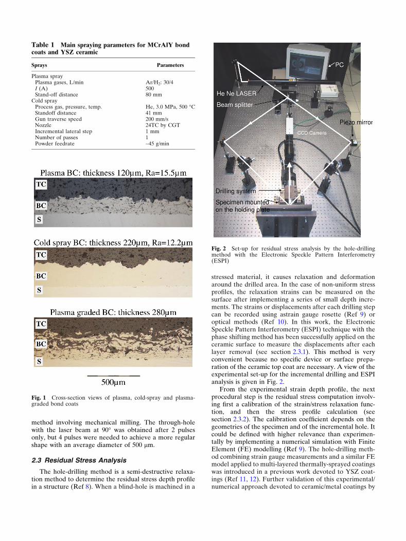
stressed material, it causes relaxation and deformationaround the drilled area. In the case of non-uniform stressprofiles, the relaxation strains can be measured on thesurface after implementing a series of small depth incre-ments. The strains or displacements after each drilling stepcan be recorded using astrain gauge rosette (Ref 9) oroptical methods (Ref 10). In this work, the ElectronicSpeckle Pattern Interferometry (ESPI) technique with thephase shifting method has been successfully applied on theceramic surface to measure the displacements after eachlayer removal (see section 2.3.1). This method is veryconvenient because no specific device or surface prepa-ration of the ceramic top coat are necessary. A view of theexperimental set-up for the incremental drilling and ESPIanalysis is given in Fig. 2.
From the experimental strain depth profile, the nextprocedural step is the residual stress computation involv-ing first a calibration of the strain/stress relaxation func-tion, and then the stress profile calculation (seesection 2.3.2). The calibration coefficient depends on thegeometries of the specimen and of the incremental hole. Itcould be defined with higher relevance than experimen-tally by implementing a numerical simulation with FiniteElement (FE) modelling (Ref 9). The hole-drilling meth-od combining strain gauge measurements and a similar FEmodel applied to multi-layered thermally-sprayed coatingswas introduced in a previous work devoted to YSZ coat-ings (Ref 11, 12). Further validation of this experimental/numerical approach devoted to ceramic/metal coatings by
Table 1 Main spraying parameters for MCrAlY bondcoats and YSZ ceramic
Sprays Parameters
Plasma sprayPlasma gases, L/min Ar/H2: 30/4I (A) 500Stand-off distance 80 mm
Cold sprayProcess gas, pressure, temp. He, 3.0 MPa, 500 !CStandoff distance 41 mmGun traverse speed 200 mm/sNozzle 24TC by CGTIncremental lateral step 1 mmNumber of passes 1Powder feedrate ~45 g/min
Fig. 1 Cross-section views of plasma, cold-spray and plasma-graded bond coats
Fig. 2 Set-up for residual stress analysis by the hole-drillingmethod with the Electronic Speckle Pattern Interferometry(ESPI)

thermal spray has been confirmed by several authors withthe assessment of the influence of different sources oferror (Ref 13, 14).
In this study, both as-sprayed and laser-drilled speci-mens were analysed by the hole-drilling method. Theconventional method was applied to bulk coatingswhereas a modified method to determine the residualstress profile around a pre-drilled hole was developed. Forthe latter, a concentric blind-hole was machined with alarger diameter than the trough-hole achieved by the la-ser. The same TBC plate was used for both analyses. Thedrilling parameters for the residual stress analysis are asfollows: drilling speed: 5000 rpm, drilling tool: 3-teethmilling bit, no cooling medium, blind-hole diameter:2 mm, incremental depth: 20 lm. In Fig. 3, a cross-sectionview of a laser-drilled specimen after the hole-drillingmethod is shown. The final depth of the blind-hole was1 mm in order to analyse the residual stress profile in theceramic in the bond coat and stop the analysis in the nearregion of the BC/S interface. It can be seen in Fig. 3 thatsome misalignment between the blind-hole and the pre-existing through-hole might have occurred. It was assumedin this study that the larger volume of material removedby milling was minimizing the error induced by the cen-tring of the two holes.
2.3.1 Displacements by ESPI. The temporal phaseshifting method was used (Ref 10, 15, 16). The beam phaseof the interferometry set-up (see Fig. 2) was shifted with amirror mounted on a piezo-translator (laser k = 632.8 nm,angle h = 45!). In the present study, 4 phase steps wererecorded and, for each phase step, the intensity I(x, y)
k of aspeckle pattern k was equal to:
Ikðx; yÞ ¼ Io x; yð Þ ð1þ c x; yð Þ & cos / x; yð Þ þ /i
! "ðEq 1Þ
For k = 1, 2, 3, 4 and where Io(x, y) is the intensity of thelaser light, c(x, y) the fringe contrast and /(x, y) theoptical phase to be determined. /i is a value associated
with each pixel of the mapped region. The optical phase iscalculated by:
tan /ðx; yÞ ¼ I4ðx; yÞ ! I2ðx; yÞI1ðx; yÞ ! I3ðx; yÞ
# $ðEq 2Þ
Measuring the phase map of one illuminated drilled area,the surface incremental displacement was determinedfrom the phase map subtraction by:
Uxðx; yÞ ¼D/ðx; yÞk4p sin h
ðEq 3Þ
where D/ðx; yÞ is the optical phase difference due to the ob-ject deformation. The displacements map was recorded aftereach drilling step. An example of a TBC top surface dis-placement map obtained after several steps is given in Fig. 4.
As represented in Fig. 4, the experimental strain wascalculated with a "digital! gauge length of 1.5 mm betweenthe two same pixels for each increment (U1, U2: couple ofdisplacements).
2.3.2 Residual Stress Profiles. Some general hypothesesfor both bulk and pre-drilled cases are assumed to calculatestress from displacement measurement. (1) Isotropic andlinear elastic behaviour of materials, (2) continuous dis-placements and homogeneous in-plane stress for each step,(3) normal stress negligible, (4) no plastic deformation due tostress release, and (5) no additional stress induced by milling.A further assumption was made in this work in order toconsider only an equi-biaxial stress field within the material.This would lead to isotropic displacements after each drillingstep. This deformation behaviour was ascertained with aMoire analysis on plasma-sprayed TBC by Wu et al. (Ref 17).Therefore, from the theory of stress relaxation around a holein cases of an equi-biaxial stress state, the released strain canbe related to the residual stress according to Eq 4, where rj
and ej are the residual stress and strain corresponding to thejth increment, and Ajj is a calibration coefficient depending ofthe geometry.
rj ¼ej
2AjjðEq 4Þ
Due to relaxation after each drilling step, the residualstress distribution remaining in the underneath layers be-
Fig. 3 Cross-section view of a laser-drilled TBC (90!) after thehole-drilling method
Fig. 4 Displacements map converted from ESPI phase image(e.g. hole depth 840 lm)
comes modified. Therefore, the measured relaxation straininduced by further incremental drillings can be derivedfrom the cumulative modification of stress due to theprevious removals of the upper increments. The "true!residual stress profile resulting from a total sequence of jincrements can be calculated by implementing an integralmethod (Ref 8, 9). This method written in a discrete formneeds a numerical calibration of the strain/stress rela-tionship in each incremental layer after each drilling step,as expressed in Eq 5.
eij ¼ 2Aijri; with 1 ' i ' j ðEq 5ÞIn Eq 5, Aij is a calibration coefficient that corresponds toa strain generated after the jth drilling step and induced bya unit hydrostatic stress in the ith increment. In this work,the series of calibration coefficients Aij for each incre-mental step were computed through a 3D finite elementanalysis (ABAQUS/CAE software). Two axisymmetric3D models were built to simulate the strain relaxation eij
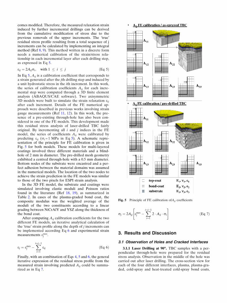
after each increment. Details of the FE numerical ap-proach were described in previous works involving straingauge measurements (Ref 11, 12). In this work, the pre-sence of a pre-existing through-hole has also been con-sidered in one of the FE models. This development madethis residual stress analysis of laser-drilled TBC fairlyoriginal. By incrementing all i and j indices in the FEmodel, the series of coefficients Aij were calibrated bypredicting eij (ri = 1 MPa in Eq 5). A schematic repre-sentation of the principle for FE calibration is given inFig. 5 for both models. These models for multi-layeredcoatings involved three different materials and a blind-hole of 2 mm in diameter. The pre-drilled mesh geometryexhibited a centred through-hole with a 0.5 mm diameter.Bottom nodes of the substrate were encastred and a per-fect adhesion between the material domains was assumedin the numerical models. The location of the two nodes toachieve the strain prediction in the FE models was similarto those of the two pixels for ESPI strain analysis.
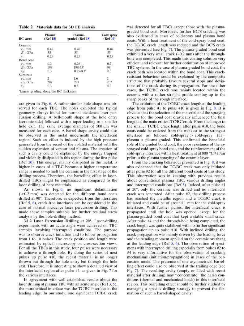
In the 3D FE model, the substrate and coatings weresimulated involving elastic moduli and Poisson ratiosfound in the literature (Ref 18, 19), as summarized inTable 2. In cases of the plasma-graded bond coat, thecomposite modulus was the weighted average of themoduli of the two constituents according to a lineargrading between NiCrAlY and YSZ along the thickness ofthe bond coat.
After computing Aij calibration coefficients for the twodifferent FE models, an iterative analytical calculation ofthe "true! strain profile along the depth of j increments canbe implemented according Eq 6 and experimental strainmeasurements emes
j .
ej ¼ emesj !
Xi¼j!1
i¼1
eij ðEq 6Þ
Finally, with an combination of Eqs 4, 5 and 6, the generaliterative expression of the residual stress profile from themeasured strain involving predicted Aij could be summa-rized as in Eq 7.
rj ¼ 2Ajj emesj !
Xi¼j!1
i¼1
2 &Aij & ri
" #ðEq 7Þ
3. Results and Discussion
3.1 Observation of Holes and Cracked Interfaces
3.1.1 Laser Drilling at 90!. TBC samples with a per-pendicular through-hole were prepared for the residualstress analysis. Observation in the middle of the hole wascarried out after laser drilling. The cross-section view foreach of the four different interfaces, plasma, plasma-gra-ded, cold-spray and heat-treated cold-spray bond coats,
Fig. 5 Principle of FE calibration ofAjj coefficients
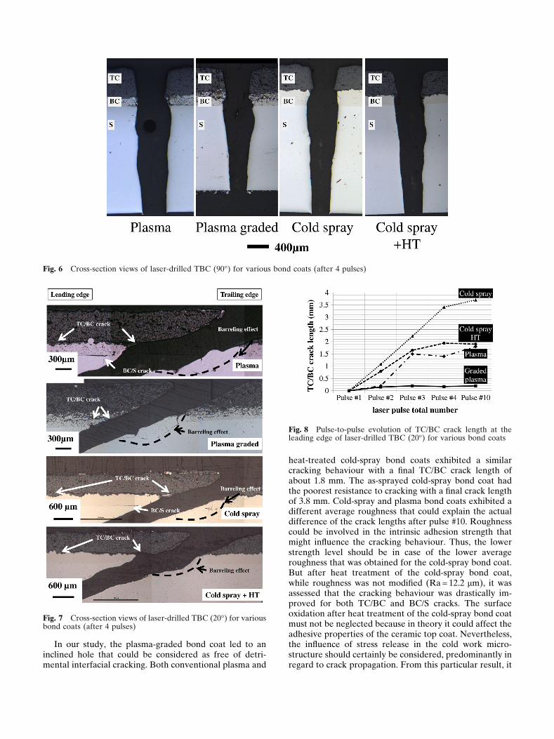
are given in Fig. 6. A rather similar hole shape was ob-served for each TBC. The holes exhibited the typicalgeometry always found for normal incidence laser per-cussion drilling. A bell-mouth shape at the hole entry(ceramic side) followed with a taper leading to a smallerhole exit. The same average diameter of 500 lm wasmeasured for each case. A barrel-shape cavity could alsobe observed in the metal underneath the interfacialregion. Such an effect is induced by the high pressuregenerated from the recoil of the ablated material with thesudden expansion of vapour and plasma. The creation ofsuch a cavity could be explained by the energy trappedand violently dissipated in this region during the first pulse(Ref 20). This energy, mainly dissipated in the metal, ishigher in cases of a TBC because a higher temperaturerange is needed to melt the ceramic in the first stage of thedrilling process. Therefore, the barrelling effect in laser-drilled TBCs might be emphasized as compared to thelaser drilling of bare materials.
As shown in Fig. 6, no significant delamination(<0.2 mm) was detected for the different bond coatsdrilled at 90!. Therefore, as expected from the literature(Ref 5, 6), crack-free interfaces can be considered in thecase of normal incidence laser percussion drilling. Thismade these samples suitable for further residual stressanalysis by the hole-drilling method.
3.1.2 Laser Percussion Drilling at 20!. Laser-drillingexperiments with an acute angle were achieved on TBCsamples involving interrupted conditions. The purposewas to observe crack initiation and to follow propagationfrom 1 to 10 pulses. The crack position and length wereestimated by optical microscopy on cross-section views.For all the TBCs in this study, four pulses were necessaryto achieve a through-hole. By doing the series of nextpulses up pulse #10, the recast material is no longerthrown out through the hole entry but through the holeexit. Therefore, it is interesting to show a detailed view ofthe interfacial region after pulse #4, as given in Fig. 7 forthe various interfaces.
In agreement with well-established results about thelaser drilling of plasma TBC with an acute angle (Ref 3, 5),the more critical interface was the TC/BC interface at theleading edge. In our study, one significant TC/BC crack
was detected for all TBCs except those with the plasma-graded bond coat. Moreover, further BC/S cracking wasalso evidenced in cases of cold-spray and plasma bondcoats. With a heat treatment of the cold-spray bond coat,the TC/BC crack length was reduced and the BC/S crackwas prevented (see Fig. 7). The plasma-graded bond coatexhibited a very small crack (~0.2 mm) after the through-hole was completed. This made this coating solution veryefficient and relevant for further optimization of improvedTBC systems. In the case of plasma-graded bond coat, thecrack path was located within the bond coat. This crack-resistant behaviour could be explained by the compositestructure that probably favours several stops and devia-tions of the crack during its propagation. For the othercases, the TC/BC crack was mainly located within theceramic with a rather straight profile coming up to thesharp peaks of the rough interface.
The evolution of the TC/BC crack length at the leadingedge from pulse #1 to pulse #10 is given in Fig. 8. It isobvious that the selection of the material and the sprayingprocess for the bond coat drastically influenced the finallength of the main critical TC/BC crack. From the longer tothe smaller TC/BC crack length after pulse #10, the bondcoats could be ordered from the weakest to the strongestinterface as follows: cold-spray > cold-spray HT =plasma > plasma-graded. This confirmed the beneficialrole of the graded bond coat, the poor resistance of the as-sprayed cold-spray bond coat, and the reinforcement of thecold-spray interface with a heat treatment at 800 !C/4H/airprior to the plasma spraying of the ceramic layer.
From the cracking behaviour presented in Fig. 8, it wasalso evidenced that the TC/BC crack was only initiatedafter pulse #2 for all the different bond coats of this study.This observation was in keeping with previous resultsabout conventional plasma TBC, various drilling anglesand interrupted conditions (Ref 5). Indeed, after pulse #1at 20!, only the ceramic was drilled and no interfacialcrack was generated. After pulse #2, the drilling processhas reached the metallic region and a TC/BC crack isinitiated and could be of around 1 mm for the cold-sprayinterfaces. With further pulses, the interfacial crack ispropagated until the hole was opened, except for theplasma-graded bond coat that kept a stable small crack.After pulse #4 and the through-hole being completed, thecrack length was quite stabilized with no further significantpropagation up to pulse #10. With inclined drilling, thecrack propagation was mainly driven by the loading forceand the bending moment applied on the ceramic overhangat the leading edge (Ref 5, 6). The observation of speci-mens with interrupted drilling especially from pulses #2 to#4 is very informative for the observation of crackingmechanisms (initiation/propagation) in cases of the per-cussion mode. The presence of one asymmetrical barrel-ling effect could also be observed at the trailing edge (seeFig. 7). The resulting cavity (empty or filled with recastmaterial after drilling) may ‘‘concentrate’’ the harsh con-ditions (thermal and mechanical loads) in this interfacialregion. This barrelling effect should be further studied bymanaging a specific drilling strategy to prevent the for-mation of such a barrel-shaped cavity.
Table 2 Materials data for 3D FE analysis
BC casesPlasma
(Ref 18)Plasma-
graded (Ref 18)Cold spray
(Ref 19)
Ceramice1, mm 0.46 0.46 0.46E1, GPa 55 55 55m1 0.25 0.25 0.25
Bond coate2, mm 0.2 0.26 0.21E2, GPa 198 198-55a 98m2 0.3 0.25-0.3a 0.3
Substratee3, mm 2 1.6 2E3, GPa 207 207 207m3 0.3 0.3 0.3
aLinear grading along the BC thickness
In our study, the plasma-graded bond coat led to aninclined hole that could be considered as free of detri-mental interfacial cracking. Both conventional plasma and
heat-treated cold-spray bond coats exhibited a similarcracking behaviour with a final TC/BC crack length ofabout 1.8 mm. The as-sprayed cold-spray bond coat hadthe poorest resistance to cracking with a final crack lengthof 3.8 mm. Cold-spray and plasma bond coats exhibited adifferent average roughness that could explain the actualdifference of the crack lengths after pulse #10. Roughnesscould be involved in the intrinsic adhesion strength thatmight influence the cracking behaviour. Thus, the lowerstrength level should be in case of the lower averageroughness that was obtained for the cold-spray bond coat.But after heat treatment of the cold-spray bond coat,while roughness was not modified (Ra = 12.2 lm), it wasassessed that the cracking behaviour was drastically im-proved for both TC/BC and BC/S cracks. The surfaceoxidation after heat treatment of the cold-spray bond coatmust not be neglected because in theory it could affect theadhesive properties of the ceramic top coat. Nevertheless,the influence of stress release in the cold work micro-structure should certainly be considered, predominantly inregard to crack propagation. From this particular result, it
Fig. 6 Cross-section views of laser-drilled TBC (90!) for various bond coats (after 4 pulses)
Fig. 7 Cross-section views of laser-drilled TBC (20!) for variousbond coats (after 4 pulses)
Fig. 8 Pulse-to-pulse evolution of TC/BC crack length at theleading edge of laser-drilled TBC (20!) for various bond coats
was evidenced that pre-existing residual stress within abond coat could have a major role in crack propagation atthe interface. In general, the actual steep gradient, due todifferent mechanical and thermal properties betweenlayers within a multi-layered system, could play animportant role in the resulting cracking behaviour. In thiscontext, the use of a graded interface would also be ben-eficial to better accommodate the steep deformationduring laser drilling. From this discussion, it was inter-esting to consider the analysis of the residual stress beforeand after laser drilling.
3.2 Residual Stress Analysis by the Hole-DrillingMethod
Numerous papers have been devoted to the residualstress (RS) analysis of conventional plasma-sprayed TBCinvolving destructive, semi-destructive or fully non-destructive methods (Ref 21, 22). The main issue is toanalyse an overall residual stress state owing to differentsources of deformation during the process, also includingthe surface preparation. Among the existing methods, thehole-drilling method has shown numerous advantagesbecause it allows the achieving of residual stress profiles.With the help of 3D FE analysis, it could be envisaged toachieve the experimental analysis by the hole-drillingmethod on local areas of shaped components and within amulti-layered system like TBC (Ref 12). By developingthe hole-drilling method on laser pre-drilled TBC samples,the purpose was to estimate whether further residualstress could be induced and/or released by the laser-dril-ling process, and to compare the evolution of residualstress of various interfaces before and after laser drilling.
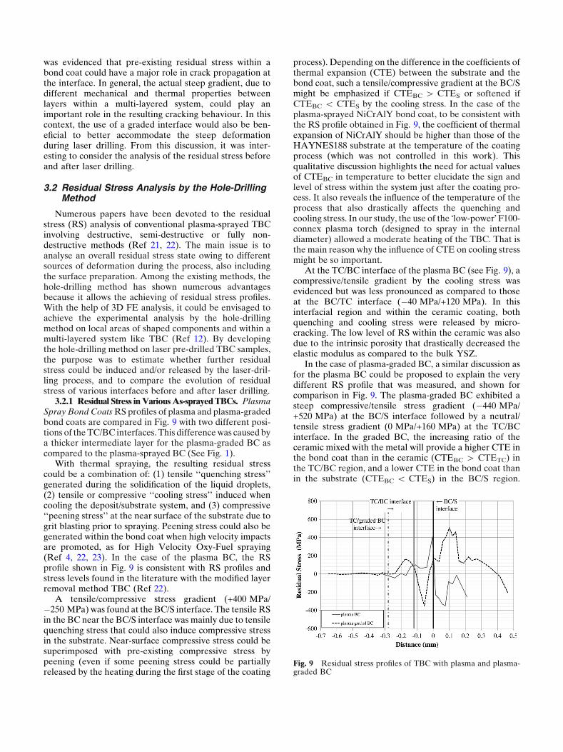
3.2.1 Residual Stress in Various As-sprayed TBCs. PlasmaSpray Bond Coats RS profiles of plasma and plasma-gradedbond coats are compared in Fig. 9 with two different posi-tions of the TC/BC interfaces. This difference was caused bya thicker intermediate layer for the plasma-graded BC ascompared to the plasma-sprayed BC (See Fig. 1).
With thermal spraying, the resulting residual stresscould be a combination of: (1) tensile ‘‘quenching stress’’generated during the solidification of the liquid droplets,(2) tensile or compressive ‘‘cooling stress’’ induced whencooling the deposit/substrate system, and (3) compressive‘‘peening stress’’ at the near surface of the substrate due togrit blasting prior to spraying. Peening stress could also begenerated within the bond coat when high velocity impactsare promoted, as for High Velocity Oxy-Fuel spraying(Ref 4, 22, 23). In the case of the plasma BC, the RSprofile shown in Fig. 9 is consistent with RS profiles andstress levels found in the literature with the modified layerremoval method TBC (Ref 22).
A tensile/compressive stress gradient (+400 MPa/!250 MPa) was found at the BC/S interface. The tensile RSin the BC near the BC/S interface was mainly due to tensilequenching stress that could also induce compressive stressin the substrate. Near-surface compressive stress could besuperimposed with pre-existing compressive stress bypeening (even if some peening stress could be partiallyreleased by the heating during the first stage of the coating
process). Depending on the difference in the coefficients ofthermal expansion (CTE) between the substrate and thebond coat, such a tensile/compressive gradient at the BC/Smight be emphasized if CTEBC > CTES or softened ifCTEBC < CTES by the cooling stress. In the case of theplasma-sprayed NiCrAlY bond coat, to be consistent withthe RS profile obtained in Fig. 9, the coefficient of thermalexpansion of NiCrAlY should be higher than those of theHAYNES188 substrate at the temperature of the coatingprocess (which was not controlled in this work). Thisqualitative discussion highlights the need for actual valuesof CTEBC in temperature to better elucidate the sign andlevel of stress within the system just after the coating pro-cess. It also reveals the influence of the temperature of theprocess that also drastically affects the quenching andcooling stress. In our study, the use of the "low-power! F100-connex plasma torch (designed to spray in the internaldiameter) allowed a moderate heating of the TBC. That isthe main reason why the influence of CTE on cooling stressmight be so important.
At the TC/BC interface of the plasma BC (see Fig. 9), acompressive/tensile gradient by the cooling stress wasevidenced but was less pronounced as compared to thoseat the BC/TC interface (!40 MPa/+120 MPa). In thisinterfacial region and within the ceramic coating, bothquenching and cooling stress were released by micro-cracking. The low level of RS within the ceramic was alsodue to the intrinsic porosity that drastically decreased theelastic modulus as compared to the bulk YSZ.
In the case of plasma-graded BC, a similar discussion asfor the plasma BC could be proposed to explain the verydifferent RS profile that was measured, and shown forcomparison in Fig. 9. The plasma-graded BC exhibited asteep compressive/tensile stress gradient (!440 MPa/+520 MPa) at the BC/S interface followed by a neutral/tensile stress gradient (0 MPa/+160 MPa) at the TC/BCinterface. In the graded BC, the increasing ratio of theceramic mixed with the metal will provide a higher CTE inthe bond coat than in the ceramic (CTEBC > CTETC) inthe TC/BC region, and a lower CTE in the bond coat thanin the substrate (CTEBC < CTES) in the BC/S region.
Fig. 9 Residual stress profiles of TBC with plasma and plasma-graded BC

This is also accompanied by a similar evolution withYoung!s moduli that will also amplify the stress calculatedfrom the actual measured strain near the BC/S interface.Therefore, cooling stress could lead to two opposite stressgradients through each interface of the plasma-gradedTBC. The stress gradient at the BC/S interface alsoexhibited some tensile stress within the bond coat in thenear interface (in keeping with the quenching stress in thisregion). The high level of tensile stress within the sub-strate is more "unexpected!. In this case, it means that thepeening stress has been neutralized by the tensile cooling/quenching stress. This comparative discussion could bemore enlightened by noting that the thermal history dur-ing the plasma-graded BC was probably very differentfrom those of the plasma BC. Firstly, it led to a higheronset temperature for the cooling because no interruptionbetween TC and BC spraying was operated. Secondly, theaddition of a ceramic into the metal promoted highertemperatures in this region. All these thermal aspectscombined with a thicker intermediate layer in the case ofplasma-graded BC explain the predominant influence andthe high level of cooling stress within a TBC with a plas-ma-graded BC. Finally, such very different RS profiles willbe strongly modified in service, but could play an impor-tant role because laser-drilling operations are achievedjust after the thermal-spraying process.
Cold-Spray Bond Coats Much less work has beendevoted to RS profiles in cold-spray coatings (Ref 24, 25).Residual stresses within the coating are mainly induced bya peening effect with severe plastic deformation (coldwork microstructure) of particles. The peening effectduring cold spraying could also affect the substrate withcompressive stress. Thermal effects that could generatecooling stress could not be avoided. The heat transfer willbe more effective for a very thick coating with a long timeexposure to the hot gases and to the flow of high velocityparticles. This was not the case in this study because asingle pass coating was implemented, while helium wasused as the processing gas heated to 500 !C. RS profiles ofcold-spray and heat-treated cold-spray bond coats areplotted in Fig. 10.
As-sprayed cold-spray CoNiCrAlY led to a tensile/compressive stress gradient (+160 MPa/!400 MPa) at theBC/S interface and a rather slight tensile/compressivestress (+50 MPa/!50 MPa) at the TC/BC interface. Thecold-spray CoNiCrAlY bond coat is mainly tensile alongits thickness with a tensile peak (+400 MPa) in the middleof the bond coat. If only peening stress was generated byhigh velocity impact of solid particles, it would have led tocompressive stress. In the case of a single pass coating,such a tensile peak within the cold-spray BC could not beexplained by a multi-pass coating with inter-pass stressrelease, as suggested in the literature (Ref 25). In a recentwork, tensile residual stress was already detected withoutambiguity in an aluminium cold-spray coating (withnitrogen processing gas at 350 !C and 2.5 MPa) usingin situ deflection measurements made by Suhonen et al.(Ref 24). According to these authors, thermal stress couldbe the origin of tensile stress within a cold-spray layer. Inour case, the use of helium with a higher thermal con-
ductivity than nitrogen, and also processed at high tem-perature and pressure (see Table 2), might have asignificant influence on heat transfer to the coating systemand the resulting thermal stress. Moreover, in the case ofour TBC system, tensile stress within the cold-spray BCmight also be induced by cooling stress due to the ceramicby plasma spraying. As for plasma bond coat, this resultbrings out the lack of data about the thermo-mechanicalproperties of cold-sprayed coatings in the as-sprayed statefor the better understanding of residual stress generationduring the process. In Fig. 10, it can be clearly seen thatheat-treated cold-sprayed CoNiCrAlY TBC led to astress-free sample. This result is consistent with theannealing of a cold worked microstructure and the releaseof stress at the TC/BC interface.
3.2.2 Residual Stress After Laser Drilling in VariousTBCs. The various RS profiles before and after laserdrilling (drilling incidence 90!) are given in Fig. 11 foreach interface. In laser-drilled specimens, the stressaround the hole results from the stress release due to thematerial removal but also from stress induced by the laser.Even if the pulse duration is short, the high rate thermaland mechanical effects are inherent in the process. Theseeffects are mainly driven by the hot gas recoil pressure butalso by the melted material (flow of ejected material orrecast material lining the hole). In the case of normalincidence drilling, the first pulse was deep enough to drillthe ceramic, the bond coat and the substrate simulta-neously. Therefore, the mismatch of properties betweeneach layer could play an important role on the resultingstress release or generation during the first pulse.
For each TBC interface in Fig. 11a–d, it was evidencedthat a RS profile obtained in a laser-drilled area is alwaysdifferent from those measured in a bulk region. Each RSanalysis before and after laser drilling was carried out onthe same TBC plate. This means that the laser-drillingprocess drastically affects the RS state around the hole.Moreover, from the large volume of material removed bythe hole-drilling method, it is likely that the RS modifi-cation by laser drilling is a long-range modification (inmm).
Fig. 10 Residual stress profiles of TBC with cold-spray andcold-spray heat-treated BC
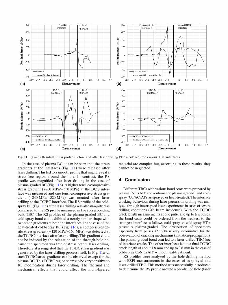
In the case of plasma BC, it can be seen that the stressgradients at the interfaces (Fig. 11a) were released afterlaser drilling. This led to a smooth profile that might reveal astress-free region around the hole. In contrast, the RSprofile was magnified after laser drilling in the case ofplasma-graded BC (Fig. 11b). A higher tensile/compressivestress gradient (+760 MPa/!550 MPa) at the BC/S inter-face was measured and one tensile/compressive stress gra-dient (+240 MPa/!320 MPa) was created after laserdrilling at the TC/BC interface. The RS profile of the cold-spray BC (Fig. 11c) after laser drilling was also magnified ascompared to the RS profile measured in the correspondingbulk TBC. The RS profiles of the plasma-graded BC andcold-spray bond coat exhibited a nearly similar shape withtwo steep gradients at both the interfaces. In the case of theheat-treated cold-spray BC (Fig. 11d), a compressive/ten-sile stress gradient (!120 MPa/+160 MPa) was detected atthe TC/BC interface after laser drilling. This gradient couldnot be induced by the relaxation of the through-hole be-cause the specimen was free of stress before laser drilling.Therefore, it is suggested that the TC/BC stress gradient wasgenerated by the laser-drilling process itself. In Fig. 11a–d,such TC/BC stress gradients can be observed except for theplasma BC. This TC/BC region seems to be very sensitive toRS modification during laser drilling. The thermal andmechanical effects that could affect the multi-layered
material are complex but, according to these results, theycannot be neglected.
4. Conclusion
Different TBCs with various bond coats were prepared byplasma (NiCrAlY conventional or plasma-graded) and cold-spray (CoNiCrAlY as-sprayed or heat-treated). The interfacecracking behaviour during laser percussion drilling was ana-lysed through interrupted laser experiments in cases of severedrilling conditions (20! beam incidence). With the TC/BCcrack length measurements at one pulse and up to ten pulses,the bond coats could be ordered from the weakest to thestrongest interface as follows: cold-spray > cold-spray HT =plasma > plasma-graded. The observation of specimensespecially from pulses #2 to #4 is very informative for theobservation of cracking mechanisms (initiation/propagation).The plasma-graded bond coat led to a laser-drilled TBC freeof interface cracks. The other interfaces led to a final TC/BCcrack length of about 1.8 mm and up to 3.8 mm in the case ofcold-spray CoNiCrAlY without heat-treatment.
RS profiles were analysed by the hole-drilling methodwith ESPI measurements in the cases of as-sprayed andlaser-drilled TBC. This method was successfully introducedto determine the RS profile around a pre-drilled hole (laser
Fig. 11 (a)–(d) Residual stress profiles before and after laser drilling (90! incidence) for various TBC interfaces
beam with normal incidence). RS profiles were measuredfor each interface before and after laser drilling. Plasma-spray BC and plasma-graded BC exhibited two oppositestress gradients at the BC/S interface and a nearly similargradient at the TC/BC interface with a zero stress within theceramic. These results highlighted the predominant role onRS profile of cooling stress and CTE at the temperature ofthe process (not the service temperature). This RS statecould play an important role because laser-drilling opera-tions are achieved just after the thermal-spraying process.CoNiCrAlY cold-spray bond coats exhibited a tensile peakwithin the layer (+400 MPa). This "unexpected! sign ofstress could still be attributed to thermal stress, but furtherstudy is needed to better clarify the stress formation inCoNiCrAlY cold-spray coatings. After heat-treatment, thecold-spray TBC was annealed and free of stress. It is con-cluded that the residual stress modification within the cold-spray layer could have a predominant role in crack forma-tion and propagation.
RS profiles are drastically modified after laser drilling.Stress could be slightly released or enhanced as comparedto RS profiles before laser drilling. In the case of thestress-free heat-treated cold-spray BC, a stress gradientwas detected at the TC/BC interface after laser drilling.Such a stress gradient was necessarily generated by thelaser-drilling process itself. The TC/BC interface seems tobe very sensitive to RS modification during laser drilling.Further work is needed to better discriminate the stressrelease due to material removal from the stress induced bythe laser drilling. To that purpose, smooth mechanicaldrilling without heat and strong mechanical effects shouldbe prepared experimentally with a similar diameter tothose obtained by percussion laser drilling. Further ana-lysis with the hole-drilling method applied on such pre-drilled holes will ascertain the actual influence of laserdrilling on the RS state around the hole. This aspect mightbe crucial to envisage multi-hole patterns for their influ-ence on the component geometry and also to betterunderstand the role of RS profiles on interfacial damage.
It is concluded that both the nature of the bond coatand the residual stress can have a major role in eliminatingceramic delamination during laser drilling.
Acknowledgments
This work was founded by the French ResearchAgency (‘‘Materiaux et Procedes’’ ULTRA project) andthe ASTech ‘‘pole de competitivite’’ for aeronautics.Industrial partners of the project (CRMA, LASAG, LaserTechnologie, SNECMA – SAFRAN group) are gratefullyacknowledged for their contributions.
References
1. W. Schulz, U. Eppelt, and R. Poprawe, Review on Laser DrillingI. Fundamentals, Modeling, and Simulation, J. Laser Appl., 2013,25, p 012006
2. A. Corcoran, L. Sexton, B. Seaman et al., The Laser Drilling ofMulti-layer Aerospace Material Systems, J. Mater. Process.Technol., 2002, 123, p 100–106
3. H.K. Sezer and N. Li, Mechanisms of Acute Angle Laser DrillingInduced Thermal Barrier Coating Delamination, J. Manuf. Sci.Eng., 2009, 131, 051014, p. 6
4. K.T. Voisey and T.W. Clyne, Laser Drilling of Cooling HolesThrough Plasma Sprayed Thermal Barrier Coatings, Surf. Coati.Technol., 2004, 176, p 296-306
5. J. Girardot, M. Schneider, L. Berthe et al., Investigation ofDelamination Mechanisms During a Laser Drilling on a Cobalt-Base Superalloy, J. Mater. Process. Technol., 2013, 213, p 1682-1691
6. J. Kamalu, P. Byrd, and A. Pitman, Variable Angle Laser Drillingof Thermal Barrier Coated Nimonic, J. Mater. Process. Technol.,2002, 122, p 355-362
7. H.K. Sezer, L. Li, and S. Leigh, Twin Gas Jet-Assisted LaserDrilling Through Thermal Barrier-Coated Nickel Alloy Sub-strates, Int. J. Mach. Tools Manuf., 2009, 49, p 1126-1135
8. J. Lu, Handbook of Measurement of Residual Stresses, TheFairmont Press, Lilburn, 1996
9. G.S. Schajer, Hole-Drilling Residual Stress Measurements at 75:Origins, Advances, Opportunities, Exp. Mech., 2010, 50, p 245-253
10. F.V. Dıaz, G.H. Kaufmann, and O. Moller, Residual StressDetermination Using Blind-Hole Drilling and Digital SpecklePattern Interferometry with Automated Data Processing, Exp.Mech., 2001, 41, p 319-323
11. G. Montay, A. Cherouat, J. Lu et al., Development of the High-precision Incremental-step Hole-drilling Method for the Study ofResidual Stress in Multi-layer Materials: Influence of Tempera-ture and Substrate on ZrO2-Y2O3 8 wt.% Coatings, Surf. Coat.Technol., 2002, 155, p 152-160
12. G. Montay, A. Cherouat, A. Nussair et al., Residual Stresses inCoating Technology, J. Mater. Sci. Technol., 2004, 20, p 81-84
13. E. Obelode and J. Gibmeier, Residual Stress Analysis on ThickFilm Systems by the Incremental Hole-Drilling Method: Simu-lation and Experimental Results, Exp. Mech., 2013, 53, p 965-976
14. T. Valente, C. Bartuli, M. Sebastiani et al., Implementation andDevelopment of the Incremental Hole Drilling Method for theMeasurement of Residual Stress in Thermal Spray Coatings, J.Therm. Spray Technol., 2005, 14, p 462-470
15. W. An and T.E. Carlsson, Speckle Interferometry for Measure-ment of Continuous Deformations, Optics Lasers Eng., 2003, 40,p 529-541
16. G. Cloud, Optical Methods of Engineering Analysis, CambridgeUniversity Press, 1995
17. L. Wu, J. Zhu, and H. Xie, Numerical and Experimental Inves-tigation of Residual Stress in Thermal Barrier Coatings DuringAPS Process, J. Therm. Spray Technol., 2014, 23, p 653-665
18. J. Matejicek, S. Sampath, P.C. Brand et al., Quenching, Thermaland Residual Stress in Plasma Sprayed Deposits: NiCrAlY andYSZ Coatings, Acta Materi., 1999, 47, p 607-617
19. F. Raletz, G. Ezo!o, M. Vardelle et al., Characterization of Cold-Sprayed Nickel-Base Coatings, in : ITSC 2004, Thermal Spray2004 : Advances in Technology and Applications, 10-12 may2004, Osaka (2004)
20. C.Y. Yeo, S.C. Tam, S. Jana et al., A Technical Review of theLaser Drilling of Aerospace Materials, J. Mater. Process. Tech-nol., 1994, 42, p 15-49
21. A. Portinha, V. Teixeira, J. Carneiro et al., Residual Stresses andElastic Modulus of Thermal Barrier Coatings Graded in Porosity,Surf. Coat. Technol., 2004, 188--189, p 120-128
22. C.R.C. Lima, J. Nin, and J.M. Guilemany, Evaluation of ResidualStresses of Thermal Barrier Coatings with HVOF ThermallySprayed Bond Coats Using the Modified Layer Removal Method(MLRM), Surf. Coat. Technol., 2006, 200, p 5963-5972
23. Y.C. Tsui and T.W. Clyne, An Analytical Model For PredictingResidual Stresses in Progressively Deposited Coatings Part 1:Planar Geometry, Thin Solid Films, 1997, 306, p 23-33
24. T. Suhonen, T. Varis, S. Dosta et al., Residual Stress Develop-ment in Cold Sprayed Al, Cu and Ti Coatings, Acta Mater., 2013,61, p 6329-6337
25. S. Rech, A. Trentin, S. Vezzu et al., Influence of Pre-Heated Al6061 Substrate Temperature on the Residual Stresses of Multi-pass Al Coatings Deposited by Cold Spray, J. Therm. SprayTechnol., 2011, 20, p 243-251