researcharticle single...
TRANSCRIPT
RESEARCH ARTICLE
Single-Step Fabrication of ComputationallyDesigned Microneedles by Continuous LiquidInterface ProductionAshley R. Johnson1, Cassie L. Caudill2, John R. Tumbleston3, Cameron J. Bloomquist2,Katherine A. Moga4, Alexander Ermoshkin3, David Shirvanyants3, Sue J. Mecham5, J.Christopher Luft2, Joseph M. DeSimone1,2,3,4,5,6*
1 Joint Department of Biomedical Engineering, University of North Carolina at Chapel Hill and North CarolinaState University, Chapel Hill, North Carolina, United States of America, 2 Department of MolecularPharmaceutics, University of North Carolina at Chapel Hill, Chapel Hill, North Carolina, 27510, United Statesof America, 3 Carbon, Redwood City, California, United States of America, 4 Department of Chemistry,University of North Carolina at Chapel Hill, Chapel Hill, North Carolina, United States of America,5 Lineberger Comprehensive Cancer Center Institute for Nanomedicine, University of North Carolina atChapel Hill, Chapel Hill, North Carolina, United States of America, 6 Department of Chemical andBiomolecular Engineering, University of North Carolina at Chapel Hill, Chapel Hill, North Carolina, UnitedStates of America
AbstractMicroneedles, arrays of micron-sized needles that painlessly puncture the skin, enable
transdermal delivery of medications that are difficult to deliver using more traditional routes.
Many important design parameters, such as microneedle size, shape, spacing, and compo-
sition, are known to influence efficacy, but are notoriously difficult to alter due to the complex
nature of microfabrication techniques. Herein, we utilize a novel additive manufacturing
(“3D printing”) technique called Continuous Liquid Interface Production (CLIP) to rapidly
prototype sharp microneedles with tuneable geometries (size, shape, aspect ratio, spac-
ing). This technology allows for mold-independent, one-step manufacturing of microneedle
arrays of virtually any design in less than 10 minutes per patch. Square pyramidal CLIP
microneedles composed of trimethylolpropane triacrylate, polyacrylic acid and photopoly-
merizable derivatives of polyethylene glycol and polycaprolactone were fabricated to dem-
onstrate the range of materials that can be utilized within this platform for encapsulating and
controlling the release of therapeutics. These CLIP microneedles effectively pierced murine
skin ex vivo and released the fluorescent drug surrogate rhodamine.
IntroductionMicroneedle patches are arrays of sharp, sub-millimeter-sized needles that enhance transder-mal drug delivery by physically perforating the tough outer layer of the skin to enable a thera-peutic of interest to more easily pass into the body. [1,2] Unlike hypodermic needles,microneedles are small enough that they avoid nerve endings buried deep within the skin;
PLOSONE | DOI:10.1371/journal.pone.0162518 September 8, 2016 1 / 17
a11111
OPEN ACCESS
Citation: Johnson AR, Caudill CL, Tumbleston JR,Bloomquist CJ, Moga KA, Ermoshkin A, et al. (2016)Single-Step Fabrication of Computationally DesignedMicroneedles by Continuous Liquid InterfaceProduction. PLoS ONE 11(9): e0162518.doi:10.1371/journal.pone.0162518
Editor: Masaya Yamamoto, Kyoto Daigaku, JAPAN
Received: April 28, 2016
Accepted: August 24, 2016
Published: September 8, 2016
Copyright: © 2016 Johnson et al. This is an openaccess article distributed under the terms of theCreative Commons Attribution License, which permitsunrestricted use, distribution, and reproduction in anymedium, provided the original author and source arecredited.
Data Availability Statement: All relevant data will bemade available within the paper and its supportinginformation files.
Funding: Carbon, Inc. and the Defense ThreatReduction Agency (HDTRA1-13-1-0045) providedfinancial support of this research. JRT, AE, DS, andJMD are employees of Carbon, Inc. and aided instudy design. The funders had no role in studydesign, data collection and analysis, decision topublish, or preparation of the manuscript.
Competing Interests: I have read the journal's policyand the authors of this manuscript have the following
therefore, they provide pain-free drug delivery with the potential for self-administration. [1–3]Microneedles enable transdermal drug delivery of a range of therapeutics that are difficult todeliver orally, such as proteins,[4] nucleic acids, [5] and large, hydrophobic molecules.[6]
Microneedles have been fabricated from a variety of different materials such as metal,[7,8]silicon,[9,10] and natural [11] and synthetic [12,13] polymers. Although numerous materialshave been utilized, microneedles fabricated from biocompatible materials are considered thegold standard for patient safety because they avoid immunological risks associated with acci-dental microneedle fragmentation within the skin.[11–13] Typically, an active pharmaceuticalagent (API) is uniformly distributed throughout a natural or synthetic polymeric matrix whichdissolves, swells, or degrades to release the API into the body. With appropriate matrix selec-tion, many pharmacokinetic profiles are achievable, providing improved control of therapeuticconcentrations to maximize efficacy while minimizing side effects. [11–13]
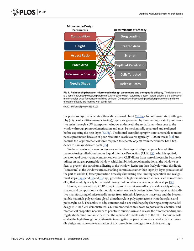
Recently, a need for improved control over microneedle design parameters, including com-position,[11,14–15] height,[16–19] sharpness,[20–21] aspect ratio,[22] inter-needle spacing,[23–25] and microneedle shape,[11,26] has been demonstrated. Such design parameters areknown to influence microneedle efficacy (Fig 1). [14,19] For example, much work has beendone to identify appropriate materials for microneedle fabrication. While metals are typicallystrong enough, biocompatible polymers must be carefully selected to have sufficient mechani-cal strength.[27] Because an efficacious microneedle must insert into the skin without breaking,both the force required for insertion and the failure strength of the material are important.[27]Microneedle shape, aspect ratio[22] and composition[11,14–15] dictate strength, whereasmicroneedle sharpness[20] and the number of needles in an array[24] influence insertionforce.
Further, microneedle design parameters influence the total amount of a therapeutic that canbe effectively delivered to the body. Because of their small size, the encapsulation and deliveryof therapeutically relevant quantities of medication is challenging for anything but the mostpotent therapeutics.[28] For this reason (and others), clinical trials using microneedles havefocused on the delivery of vaccines and hormones, which only require microgram levels to pro-duce an efficacious response. Increasing microneedle height improves maximum cargo loading(due to increased microneedle volume), but microneedles that are too tall can be painful topatients.[16] Increasing the number of microneedles in an array also improves cargo loading,but the force required to insert the array also increases with the number of needles.[24–25] Thedesign of efficacious microneedle patches is characterized by such trade-offs, complicatingmicroneedle design. Developing a fundamental understanding of effective operating windowsfor each design parameter would aid the advancement of microneedle technology.
Ideally, new microneedle designs could be rapidly prototyped to systematically invesitgateeach design parameter with the goal of optimizing efficacy. However, due to the complexnature of current microneedle fabrication techniques (such as silicon etching,[28,29] tilted UV(ultraviolet) photolithography,[11] and laser ablation[30] combined with micromolding), leadtimes for new designs are on the order of months. Further, many of these techniques have tech-nical limitations that prevent certain types of microneedles (such as tall, sharp, and/or highaspect ratio structures) from being produced. For this reason, microneedle height, aspect ratio,and spacing are typically dictated by feasibility of fabrication rather than ideal design. A num-ber of new microneedle fabrication techniques, such as drawing lithography,[31] two photonpolymerization[32] and electrodrawing,[33] have been developed to address the limitations oftraditional approaches, but are not widely adopted.
Additive manufacturing (“3D printing”) may provide a “touch-button” approach to compu-tationally designing and rapidly prototyping microneedle patches. Additive manufacturing tra-ditionally produces objects in a layer-by-layer fashion, wherein each layer is stacked on top of
Additive Manufacturing of Microneedles
PLOS ONE | DOI:10.1371/journal.pone.0162518 September 8, 2016 2 / 17
competing interests: JRT, DS, AE, and JMD all havean equity stake in Carbon, Inc., which is a venture-backed startup company. This does not alter ouradherence to PLOS One policies on data sharing andmaterials.
the previous layer to generate a three dimensional object (S1 Fig). In bottom-up stereolithogra-phy (a type of additive manufacturing), layers are generated by illuminating a vat of photoreac-tive resin through a UV transparent window underneath the resin. Layers then cure to thewindow through photopolymerization and must be mechanically separated and realignedbefore exposing the next layer (S2 Fig). Traditional stereolithography is not amenable to micro-needle production because of poor resolution (each layer is typically ~100μm thick) [34] andbecause the large mechanical force required to separate objects from the window has a ten-dency to damage delicate parts.[35]
We have developed a new continuous, rather than layer-by-layer, approach to additivemanufacturing called Continuous Liquid Interface Production (CLIP) [36] which is applied,here, to rapid prototyping of microneedle arrays. CLIP differs from stereolithography because itutilizes an oxygen permeable window, which inhibits photopolymerization at the window sur-face, to prevent the part from adhering to the window. Resin can then freely flow into this liquid“dead zone” at the window surface, enabling continuous rather than layer-by-layer production ofthe part to enable 1) faster production times by eliminating rate-limiting separation and realign-ment steps (Fig 2 and S2 and S3 Figs) generation of high resolution structures (such as micronee-dles) that would typically be damaged during traditional mechanical separation steps. [35]
Herein, we have utilized CLIP to rapidly prototype microneedles of a wide variety of sizes,shapes, and compositions with modular control over each design factor. We report rapid addi-tive manufacturing of microneedle arrays from trimethylolpropane triacrylate and the biocom-patible materials polyethylene glycol dimethacrylate, polycaprolactone trimethacrylate, andpolyacrylic acid. The ability to adjust microneedle size and shape by altering a computer aideddesign (CAD) file is demonstrated. CLIP microneedles are shown to possess the chemical andmechanical properties necessary to penetrate murine skin and release the fluorescent drug sur-rogate rhodamine. We anticipate that the rapid and tunable nature of the CLIP technique willenable the high throughput, systematic investigation of parameters associated with micronee-dle design and accelerate translation of microneedle technology into a clinical setting.
Fig 1. Relationship betweenmicroneedle design parameters and therapeutic efficacy. The left columnis a list of microneedle design parameters, whereas the right column is a list of factors affecting the efficacy ofmicroneedles used for transdermal drug delivery. Connections between input design parameters and theireffect on efficacy are marked with solid lines.
doi:10.1371/journal.pone.0162518.g001
Additive Manufacturing of Microneedles
PLOS ONE | DOI:10.1371/journal.pone.0162518 September 8, 2016 3 / 17

Materials and Methods
Synthesis of poly-ε-caprolactone trimethacrylate (PCL-tMa)Poly-ε-caprolactone (PCL) triol (Sigma Aldrich) with an average molecular weight of 900g/mol (55.14 g, 61.3 mmol) was dried in a vacuum oven. The reaction flask was equipped with anaddition funnel, sealed with rubber septa, and placed under magnetic stirring and N2 flow. Dis-tilled dichloromethane (DCM, 200mL, Fisher Scientific) and triethyamine (TEA, 275.9 mmol,Fisher Scientific) was added to a flask placed under magnetic stirring and N2 flow on an icebath. Methacryloyl chloride (Sigma Aldrich) was added dropwise from the addition funnelover one hour and the reaction proceed overnight. The formed TEA•HCl salt was filtered offand the filtrate was washed with sodium bicarbonate, dried over magnesium sulfate, and theDCM was removed by rotary evaporation.
Determination of Resin Cure DosagesMethods for the determination of cure dosage were adapted from Tumbleston et. al.[32]Briefly, 500μL of resin was placed on a cover slip on top of the printer window. Resin wasexposed to a specified dosage of light (λ = 365nm LED) in a circle pattern and residual mono-mer was removed using an acetone wash. The height of polymerized circles was then measuredusing a Mitutoyo Electronic Indicator (McMaster Carr). Resins utilized in this study wereacrylic acid (Acros Organics, 99.5% purity), a poly-ε-caprolactone trimethacrylate (PCL-tMa)synthesized in house, and poly (ethylene glycol) dimethacrylate (Mn 550, Sigma Aldrich)mixed with 2.5 wt% Diphenyl(2,4,6-trimethyl-benzoyl-)phosphine oxide(TPO,Sigma Aldrich)as a photoinitiator.
Fabrication of Trimethylolpropane Triacrylate (TMPTA) MicroneedlesTo produce microneedles of different heights, CAD files of square pyramidal microneedlesmeasuring 1000, 700, and 400 μm tall with an aspect ratio of 3 (aspect ratio = height/width)were generated using Solidworks 2014. All microneedles were spaced at one base width aparton a base measuring 6x6x1mm. CAD files were then sliced at 1μm slice thickness using the
Fig 2. Continuous Liquid Interface Production (CLIP) Process. Amicroneedle patch is computationally designed using a CAD file. Themicroneedle is then fabricated using CLIP to produce a microneedle prototype within two to ten minutes. CLIP generates the microneedle patchthrough photopolymerization of a liquid, photoreactive resin using light reflecting off of a DLP chip. Continuous (rather than layer-by-layer)fabrication of the patch is enabled by a “dead-zone” created through oxygen mediated inhibition of the photopolymerization reaction at thewindow surface. A microneedle patch of virtually any design is created in two to ten minutes.
doi:10.1371/journal.pone.0162518.g002
Additive Manufacturing of Microneedles
PLOS ONE | DOI:10.1371/journal.pone.0162518 September 8, 2016 4 / 17

open source software Slic3r. Microneedles were then produced using a CLIP additivemanufacturing system (Carbon, Redwood City, CA) in a mixture of TMPTA (Sigma Aldrich)and 2.5wt% diphenyl(2,4,6-trimethylbenzoyl)phosphine oxide (Sigma Aldrich) with 5.4mW/cm2 of UV light (λ = 370nm LED) as measured by the Dymax AccuCal™50 (Dymax Corpora-tion) at 100mm/hr. Z scale factors of 1.175, 1.175, and 1.6 were added during scaling to coun-teract z-axis truncation visualized without scaling. All microneedles were visualized using anenvironmental scanning electron microscope (FEI Quanta 200) in low vacuum mode.
To demonstrate ability to alter microneedle size and shape, CAD files were created andsliced as previously described. The CAD file used to generate microneedles of varying aspectratios contained microneedles measuring 1000μm in height and 500μm, 333μm, and 250μm inwidth for aspect ratios of 2, 3, and 4, respectively. These microneedles were spaced at 333 μmapart. CAD files for microneedles of varying spacing measured 1000μm in height and 500μmin width with spacing at 250 μm or 500μm apart.
Arrowhead microneedles measuring 1000μm tall and 500μm wide were fabricated fromTMPTA + 2.5wt% TPO (and 0.1wt% 2-(3’-tert-butyl-2’-hydroxy-5’-methylphenyl)-5-chloro-benzotriazole (Sigma Aldrich) at 41mm/hr with 5.4mW/cm2 of UV light. Tiered microneedles,measuring 1000μm, 800μm, and 600μm tall and 400μm wide, and turret microneedles measur-ing 1000μm tall and 500μmwide were fabricated at 25mm/hr with 1.35mW/cm2 of UV light.
Biocompatible MicroneedlesPoly-acrylic acid microneedles, polycaprolactone microneedles, and poly (ethylene glycol)microneedles were all printed at 25mm/hr, with 8.9, 1.5, and 1.2 mW/cm2 of light(λ = 370nmLED), respectively. All needles were washed briefly with acetone and dried using compressedair. Microneedles were imaged as previously described.
Microneedles containing multiple compositions were fabricated from polycaprolactone tri-methacrylate mixed with 0.05wt% rhodamine B base (Sigma Aldrich) and acrylic acid mixedwith 0.05wt% fluorescein (Sigma Aldrich). Both resins contained 2.5wt% TPO as a photoinitia-tor. Slices 1 through 1700 were fabricated using PCL prior to lifting the build elevator, remov-ing residual resin, and continuing to fabricate the remainder of the microneedle (slices 1701through 2000) using acrylic acid.
To test for acrylic acid microneedle dissolution, one patch with a polycaprolactone base andpolyacrylic acid microneedles contining 0.1wt% rhodamine was submerged in 10mL PBS. Themicroneedle patch was imaged before and after dissolution using a Leica MZ16FA macroscopein brightfield mode.
Skin Penetration StudiesPatches were tested on ex vivo nude murine skin with permission of the UNC InstitutionalAnimal Care and Use Committee (IACUC). Nude mice were sacrificed through inhalation ofisofluorane followed by cervical dislocation. Skin was then excised from the back and flank andall samples were stored at -20°C until testing occurred. Prior to testing, skin was thawed brieflyat room temperature and pinned over corkboard. CLIP microneedles were post-cured under amercury lamp for 5 minutes to improve mechanical strength prior to application. Microneedlepatches were then applied to the skin with 10 seconds of thumb pressure before patch removal.A 50:50 mixture of Green tissue marking dye (Cancer Diagnostics) and isopropanol was thenapplied to the site for 3 minutes before being wiped away with water and isopropanol. Skin wasimaged to visualize sites of microneedle insertion using brightfield macroscopy (Leica M420).
To further confirm skin penetration using histology, polyacrylic acid microneedles wereapplied to murine skin ex vivo with 10 seconds of thumb pressure before patch removal.
Additive Manufacturing of Microneedles
PLOS ONE | DOI:10.1371/journal.pone.0162518 September 8, 2016 5 / 17
Murine skin sections were then embedded in Tissue-Tec Optimum Temperature CuttingMedium (Sakura Finetek), bisected, and sectioned in 12 micron slices at -25°C (Leica Cryostat).Samples were H&E stained (Cryo-KIT, Cancer Diagnostics) and visualized using brightfieldmicroscopy (Olympus BX61 Upright Brightfield Microscope).
To test for dye release, polyacrylic acid microneedle patches containing 0.1wt% rhodamineB were applied to murine skin ex vivo and left to dissolve in the skin for 30 minutes. Sampleswere then briefly fixed in FROZEN-FIX (Cancer Diagnostics) for 10 seconds and visualizedusing fluorescence microscopy (Olympus BX61 Upright Fluorescence microscope).
Fabrication and Testing of Janus MicroneedlesTip-loaded microneedles were fabricated from polycaprolactone trimethacrylate mixed with0.05wt% rhodamine B base (Sigma Aldrich) and acrylic acid mixed with 0.05wt% fluorescein(Sigma Aldrich). Both resins contained 2.5wt% TPO as a photoinitiator. Slices 1 through 1700were fabricated using PCL prior to lifting the build elevator, removing residual resin, and con-tinuing to fabricate the remainder of the microneedle (slices 1701 through 2000) using acrylicacid. Microneedles were post-cured under a mercury lamp for 10 min between compositionsand after fabrication was complete.
To test for dye release from tip-loaded microneedles, tip-loaded microneedles were fabri-cated from blank polycaprolactone and a polyacrylic acid tip containing 0.1wt% rhodamine Bbase, as previously described. Microneedles were applied to murine skin ex vivo with gentlethumb pressure for a period of 10 seconds. Microneedles were then allowed to remain the theskin for a period of 30 minutes prior to imaging using a Leica MZ16FA macroscope in bright-field mode.
Results
Fabrication of TMPTAMicroneedles of Different SizesTo assess feasibility of applying CLIP to microneedle production, we investigated the fabrica-tion of microneedles using a model resin composed of trimethylolpropane triacrylate (TMPTAmixed with 2.5wt% diphenyl (2,4,6- trimethylbenzoyl) phosphine oxide (TPO) as a photoini-tiator. This model resin has been previously used in additive manufacturing because it is fast-reacting and has low viscosity;[37] therefore, the resin was used as a positive control for micro-needle composition while establishing fabrication protocols.
A computer aided design (CAD) file of the desired microneedle array containing squarepyramidal microneedles measuring 1000μm tall and 333μm wide, was generated and computa-tionally sliced along the z direction. A digital light processing (DLP) chip and an ultravioletlight emitting diode (UV LED) were used to project these slices (frames) onto an oxygen per-meable, UV-transparent window in rapid succession (Fig 2). This DLP chip is essentially anarray of micromirrors which controls the shape of the UV light distribution passing throughthe window and onto the photoreactive resin. Microneedles were fabricated with varyingamounts of UV light to determine how light intensity affects microneedle structure and dimen-sions (S4 and S5 Figs). Produced microneedles had the desired square pyramidal structureregardless of light intensity, but the size of the structure increased with increasing light inten-sity due to the increased amount of electromagnetic radiation available to initiate photopoly-merization. Although all microneedles initially truncated in the z direction relative to the CADfile (regardless of light intensity), the addition of a z scale factor during fabrication allowed forthe production of microneedles measuring within ±5% of the intended dimensions (Fig 3 andS1 Table).
Additive Manufacturing of Microneedles
PLOS ONE | DOI:10.1371/journal.pone.0162518 September 8, 2016 6 / 17

Microneedles of different heights may be desirable for controlling depth of penetration inthe skin and altering the volume available for cargo loading.[17,19] Therefore, CAD files ofmicroneedles measuring 700μm and 400μm in height were also generated with aspect ratioheld constant. Fig 3 shows that CLIP could be used to produce microneedles ranging from400μm to 1000μm in height could with remarkable consistency across the array. Patches werefabricated in less than 90 seconds per patch with tip radii measuring less than 3.5 μm (Fig 3and S1 Table).
Fabrication of TMPTAMicroneedles of Different GeometriesAs previously mentioned, the geometry of a microneedle array is known to affect its cargo load-ing volume, failure force, [22] and ability to effectively insert into the skin,[24,25] among otherfactors. In order to determine whether CLIP can be utilized to rapidly adjust patch geometry,we fabricated CLIP microneedles with different aspect ratios and spacings.
The process of altering CLIP microneedle aspect ratio only requires generation of a newCAD file, as previously described. Fig 4A demonstrates the ability to simply adjust microneedleaspect ratio from 2 to 4 while maintaining desirable microneedle morphology. Similarly, CADfiles of microneedles spaced at 0.5 and 1.5 base widths apart were readily generated and utilizedto produce CLIP microneedle patches with adjustable inter-needle spacing (Fig 4B and 4C).Microneedle height was held constant at approximately 1000μm.
Fig 3. TMPTAMicroneedles of Different Heights. TMPTAmicroneedles measuring approximately A)1000μmC) 700μm and D) 400μm in height with AR = 3. B) Representative image of a microneedle tip with atip radius of approximately 2.3μm. Scale bars measure 500μm (A, C-D) and 5μm (B), respectively. Allpatches were generated in less than 90 seconds.
doi:10.1371/journal.pone.0162518.g003
Additive Manufacturing of Microneedles
PLOS ONE | DOI:10.1371/journal.pone.0162518 September 8, 2016 7 / 17

Although conical and square pyramidal microneedles have been the mainstay of micronee-dle technology, more complex geometries may afford improved penetration into the skin. Forexample, arrowhead microneedles may improve the consistency of needle penetration byresisting the elastic nature of the skin to remain embedded at their maximum penetrationdepth.[37] Successful microneedle penetration into the skin is also known to be inhibited bythe “bed-of-nails” effect, wherein the total insertion force is divided evenly amongst everymicroneedle in an array, increasing the total force required for insertion.[24,25] The design of“tiered”microneedles, which contain microneedles of different heights on a single array, mayreduce required insertion forces by concentrating the force on fewer needles at a given momentin time. Lastly, traditional square pyramidal microneedles of different aspect ratios are thoughtto present a trade-off between ease of insertion and microneedle strength wherein wider nee-dles provide mechanical stability, but thinner needles more easily insert into the skin.[11–12]“Turret”microneedles containing sharp tips with a wide base may easily puncture the skin, butalso afford improved mechanical strength.
CLIP was utilized to fabricate arrowhead microneedles, “tiered”microneedles, and “turret”microneedles, shown in Fig 4D–4F, respectively. This work demonstrates proof of concept thatCLIP can be utilized to rapidly generate an almost infinite library of computationally definedmicroneedle geometries, which can be used to systematically investigate how geometry influ-ences efficacy.
Fabrication of Biocompatible MicroneedlesAfter establishing techniques for microneedle fabrication using a model resin, we sought to fab-ricate microneedles from biocompatible materials designed for the incorporation and release oftherapeutic cargos. The selection of an optimal microneedle matrix for a given applicationdepends on the solubility of the cargo and the desired pharmacokinetic release profile. There-fore, we investigated fabrication of CLIP microneedles from materials with a range of solubilityand release characteristics. Photopolymerizable derivatives of materials prevalent in FDAapproved medical devices were selected to maximize biocompatibility.
Monomers selected for CLIP microneedle fabrication were poly(ethylene glycol) dimetha-crylate (Mn = 550), polycaprolactone trimethacrylate (Mn = 1100) (PCL-tMa), and acrylic acid.
Fig 4. TMPTAMicroneedles of Different Shapes. A) TMPTAmicroneedles of aspect ratio 2, 3, and 4 (left toright). 1000μm tall TMPTAmicroneedles with spacing of B) 0.5 base widths and C) 1.5 base widths. Complexmicroneedle geometries such as D) Arrowhead microneedles E) Tiered microneedles and F) Turretmicroneedles may improve mechanics of insertion into the skin. Scale bars measure 500μm.
doi:10.1371/journal.pone.0162518.g004
Additive Manufacturing of Microneedles
PLOS ONE | DOI:10.1371/journal.pone.0162518 September 8, 2016 8 / 17
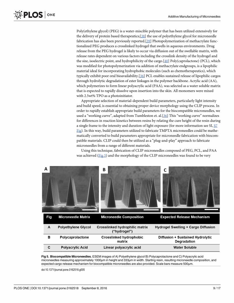
Poly(ethylene glycol) (PEG) is a water-miscible polymer that has been utilized extensively forthe delivery of protein based therapeutics;[38] the use of polyethylene glycol for microneedlefabrication has also been previously reported.[39] Photopolymerization of methacrylate func-tionalized PEG produces a crosslinked hydrogel that swells in aqueous environments. Drugrelease from the PEG hydrogel is likely to occur via diffusion out of the swellable matrix, withrelease rates dependent on various factors including the crosslink density of the hydrogel andthe size, isoelectric point, and hydrophilicity of the cargo.[40] Poly(caprolactone) (PCL), whichwas modified for photopolymerization via addition of methacrylate endgroups, is a lipophilicmaterial ideal for incorporating hydrophobic molecules (such as chemotherapeutics), whichtypically exhibit poor oral bioavailability.[36] PCL enables sustained release of lipophilic cargosthrough hydrolytic degradation of ester linkages in the polymer backbone. Acrylic acid (AA),which polymerizes to form linear polyacrylic acid (PAA), was selected as a water soluble matrixthat is expected to rapidly dissolve upon insertion into the skin. All monomers were mixedwith 2.5wt% TPO as a photoinitiator.
Appropriate selection of material-dependent build parameters, particularly light intensityand build speed, is essential to obtaining proper device morphology using the CLIP process. Inorder to rapidly establish appropriate build parameters for the biocompatible microneedles, weused a “working curve”, adapted from Tumbleston et. al.[36] This “working curve” normalizesfor differences in reaction kinetics between resins by relating the cure height of the resin duringa single frame to the intensity and duration of light exposure (for more information see SI, S7Fig). In this way, build parameters utilized to fabricate TMPTAmicroneedles could be mathe-matically converted to build parameters appropriate for microneedle fabrication with biocom-patible materials. CLIP could then be utilized as a “plug-and-play” approach to fabricatemicroneedles from a range of different materials.
Using this technique, fabrication of CLIP microneedles composed of PEG, PCL, and PAAwas achieved (Fig 5) and the morphology of the CLIP microneedles was found to be very
Fig 5. Biocompatible Microneedles. ESEM images of A) Polyethylene glycol B) Polycaprolactone and C) Polyacrylic acidmicroneedles measuring approximately 1000μm in height and 333μm in width. Starting resin, resulting microneedle composition, andexpected cargo release mechanism for biocompatible microneedles are also provided. Scale bars measure 500μm.
doi:10.1371/journal.pone.0162518.g005
Additive Manufacturing of Microneedles
PLOS ONE | DOI:10.1371/journal.pone.0162518 September 8, 2016 9 / 17

consistent between resins. These microneedles measure approximately 1000μm in height withan AR of 3, with all microneedles measuring within ±10% of their intended dimensions S2Table. Tip radii for these biocompatible microneedles measure less than approximately 10μm,with fabrication times under 10 minutes per patch.
To confirm that these microneedle compositions provide an opportunity to tailor therapeu-tic release rates, each microneedle composition was loaded with rhodamine B base as a fluores-cent drug surrogate (S8 Fig). Release of rhodamine B base into phosphate buffered saline (PBS)was assessed over a period of seven days (S9 Fig). PCL and PEG microneedles released 0.5wt%and 5wt% of loaded rhodamine over one week, respectively, whereas PAA microneedlesreleased all of the loaded rhodamine within 30 minutes in solution. In order to confirm thatPAA microneedles are completely dissolvable, rhodamine containing PAA microneedles on aPCL backing were imaged before and after submersion in aqueous media. Complete dissolu-tion of the rhodamine containing PAA microneedles is observed within 15 minutes, leavingbehind the water-insoluble PCL backing (S10 Fig). These results indicate that CLIP micronee-dle matrices can be easily altered to tune cargo release rates.
Skin Penetration and Release of Fluorescent Drug SurrogateThe ability of CLIP microneedles to puncture the skin and deliver a therapeutic cargo wasassessed using ex-vivo murine skin. Murine skin was selected for model continuity with upcom-ing in vivo studies. Microneedles of four different compositions (TMPTA, PAA, PCL, and PEG)were applied to murine skin ex vivo by pressing firmly on the back of the microneedle patcheswith the thumb for 10 seconds. The microneedle patches were then removed and a green tissuemarking dye that selectively marks sites of skin penetration was applied. All four microneedlecompositions were observed to successfully breach murine skin (Fig 6A–6D), whereas no sitesof penetration were observed on untreated skin (Fig 6E). Some qualitative differences in thepenetration efficacy of the four different microneedle compositions could be observed. Forexample, the TMPTA and PAAmicroneedles appear to produce larger sites of penetrationwithin the skin than the PCL and PEGmicroneedles, perhaps suggesting deeper penetrationinto the skin due to the superior mechanical properties. Nevertheless, these results indicates thatall four microneedle compositions exhibit sufficient strength to pierce murine skin.
Fig 6. Skin Insertion Tests. Sites of skin penetration from CLIP Microneedle arrays made of A) PCL B)TMPTA C) PEG and D) Polyacrylic acid on murine skin can be visualized using a tissue marking dye. E) Noinsertion sites are visualized on a piece of control skin to which no microneedles were applied. Scale barsmeasure 1mm.
doi:10.1371/journal.pone.0162518.g006
Additive Manufacturing of Microneedles
PLOS ONE | DOI:10.1371/journal.pone.0162518 September 8, 2016 10 / 17

As further confirmation that CLIP microneedles puncture the stratum corneum, PAAmicroneedles were applied to additional samples of murine skin ex-vivo. These skin sampleswere then fixed, cryosectioned and stained with hematoxalin and eosin. Microneedle-induceddisruption of the stratum corneum can be observed in Fig 7A, whereas untreated skin remainedintact (Fig 7B).
To assess drug release, rhodamine was incorporated into polyacrylic acid microneedles as afluorescent drug surrogate. Microneedles were applied to murine skin ex-vivo and allowed todissolve within the skin for a period of 30 minutes. Skin samples were then fixed, cryosec-tioned, and visualized with a fluorescence microscope. Rhodamine could be observed withinthe treated skin (Fig 7C), whereas no fluorescence could be observed in untreated sections (Fig7D). Together, these results suggest that CLIP microneedles can effectively deliver a drug sur-rogate into the skin.
Even though PAA CLIP microneedles dissolve to release a fluorescent drug surrogate intomurine skin within 30 minutes, it was clear that the entirety of the microneedle did not dissolvein skin (S1 Fig). Therefore, we aimed to improve the efficiency of cargo delivery to the skin bylocalizing cargo to a water soluble tip. Janus microneedles composed of two distinct materials-a water insoluble PCL base containing rhodamine and a water soluble PAA tip containing fluo-rescein were fabricated to demonstrate that the fluorescein fluorescent drug surrogate could belocalized to the microneedle tip. Fabrication of Janus microneedles was achieved by exchangingthe resin in the middle of the production process. The microneedle base was first fabricatedusing the PCL resin before pausing the build. The support plate was then lifted above the resid-ual resin pool was removed and replaced with acrylic acid resin. The remainder of the micro-needle tip was then fabricated using the AA resin.
A confocal micrograph of the fabricated Janus microneedles is given in Fig 8A. The rhoda-mine channel is displayed in red and the fluorescein channel is displayed in green. The lack ofoverlap between the two fluorescent channels indicates that fluorescein was successfully local-ized to the microneedle tip.
In order to determine whether localizing cargo to the tip improves cargo delivery, Janusmicroneedles composed of a rhodamine containing PAA tip and a blank PCL base were fabri-cated and applied to murine skin ex vivo using firm thumb pressure for a period of 30 minutes.
Fig 7. Ex-Vivo Skin Penetration and Dye Release. H&E stained skin sections show A) epidermal breachupon application of PAAmicroneedles but B) no epidermal breach in untreated control. C) The application ofrhodamine containing polyacrylic acid microneedles releases rhodamine into the skin. D) No fluorescence isvisualized in sections to which no microneedles were applied. All scale bars measure 100μm.
doi:10.1371/journal.pone.0162518.g007
Additive Manufacturing of Microneedles
PLOS ONE | DOI:10.1371/journal.pone.0162518 September 8, 2016 11 / 17
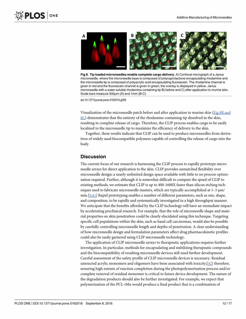
Visualization of the microneedle patch before and after application to murine skin (Fig 8B and8C) demonstrates that the entirety of the rhodamine containing tip dissolved in the skin,resulting in complete release of cargo. Therefore, the CLIP process enables cargo to be easilylocalized to the microneedle tip to maximize the efficiency of delivery to the skin.
Together, these results indicate that CLIP can be used to produce microneedles from deriva-tives of widely used biocompatible polymers capable of controlling the release of cargo into thebody.
DiscussionThe current focus of our research is harnessing the CLIP process to rapidly prototype micro-needle arrays for direct application to the skin. CLIP provides unmatched flexibility overmicroneedle design; a nearly unlimited design space available with little to no process optimi-zation required. Further, although it is somewhat difficult to compare the speed of CLIP toexisting methods, we estimate that CLIP is up to 400-1600X faster than silicon etching tech-niques used to fabricate microneedle masters, which are typically accomplished at 1–5 μm/min.[9,41] Rapid prototyping enables a number of different parameters, such as size, shape,and composition, to be rapidly and systematically investigated in a high throughput manner.We anticipate that the benefits afforded by the CLIP technology will have an immediate impactby accelerating preclinical research. For example, that the role of microneedle shape and mate-rial properties on skin penetration could be clearly elucidated using this technique. Targetingspecific cell populations within the skin, such as basal cell carcinomas, would also be possibleby carefully controlling microneedle length and depths of penetration. A clear understandingof how microneedle design and formulation parameters affect drug pharmacokinetic profilescould also be easily garnered using CLIP microneedle technology.
The application of CLIP microneedle arrays to therapeutic applications requires furtherinvestigation. In particular, methods for encapsulating and stabilizing therapeutic compoundsand the biocompatibility of resulting microneedle devices still need further development.Careful assessment of the safety profile of CLIP microneedle devices is necessary. Residualunreacted acrylic monomers and oligomers have been associated with toxicity;[42] therefore,ensuring high extents of reaction completion during the photopolymerization process and/orcomplete removal of residual monomer is critical to future device development. The nature ofthe degradation products should also be further investigated. For example, we expect thatpolymerization of the PCL-tMa would produce a final product that is a combination of
Fig 8. Tip loadedmicroneedles enable complete cargo delivery. A) Confocal micrograph of a Janusmicroneedle, where the microneedle base is composed of polycaprolactone encapsulating rhodamine andthe microneedle tip is composed of polyacrylic acid encapsulating fluorescein. The rhodamine channel isgiven in red and the fluorescein channel is given in green; the overlay is displayed in yellow. Janusmicroneedle with a water soluble rhodamine containing tip B) before and C) after application to murine skin.Scale bars measure 500μm (A) and 1mm (B-C)
doi:10.1371/journal.pone.0162518.g008
Additive Manufacturing of Microneedles
PLOS ONE | DOI:10.1371/journal.pone.0162518 September 8, 2016 12 / 17

degradable monomeric units and nondegradable crosslinks. It will be important to character-ize the molecular weight of degradation products to ensure successful elimination from thebody.
The true strength of CLIP microneedle technology, demonstrated herein, is the ability torapidly alter microneedle design. While we anticipate that successful formulation will enableCLIP microneedles to be directly utilized for therapeutic applications, there is also a powerfulopportunity to combine CLIP technology with existing micromolding techniques. The adapt-ability and speed of CLIP microneedle fabrication make it an unparalleled technique for gener-ating microneedle master templates, which could be replicated using polydimethylsiloxane(PDMS) molds. This PDMS mold could then be filled using proven micromolding techniques,which effectively stabilize a wide variety of therapeutics for delivery[1–2,11] (but with substan-tially longer fabrication times than the CLIP technique presented here).
ConclusionsTogether, these results demonstrate the ability to use CLIP to rapidly generate microneedles ofvarious sizes, shapes, aspect ratios, spacings, and compositions. CLIP microneedles puncturedmurine skin ex vivo and released the fluorescent drug surrogate rhodamine. The work pre-sented here is the fastest and most versatile microneedle prototyping scheme to date, to ourknowledge, and provides a tunable platform for the systematic study of numerous parametersassociated with transdermal delivery via microneedles. These parameters include, but are notlimited to, microneedle geometry, material properties (such as strength and elasticity), thera-peutic incorporation and release and their resulting effect on therapeutic efficacy.
Supporting InformationS1 Fig. Overview of the additive manufacturing process. A computer model is computation-ally sliced into individual layers. Each two dimensional layer is stacked on top of the previouslayer to create the desired three-dimensional part(TIF)
S2 Fig. Difference between stereolithography and CLIP.(TIF)
S3 Fig. CLIP eliminates the trade-off between slice thickness and fabrication time by elimi-nating separation and realignment steps, enabling rapid production of high resolutionstructures(TIF)
S4 Fig. TMPTAmicroneedles produced with varying light intensity.Microneedles were pro-duced using A) 2mW/cm2, B) 5mW/cm2, C) 8mW/cm2, D) 11mW/cm2, and E) 14mW/cm2 ofUV light. Build speed was held constant at 100mm/hr. Scale bars measure 500μm.(TIF)
S5 Fig. Dimensions of TMPTAmicroneedles produced with varying light intensity.Micro-needles were produced using 1.4mW/cm2, 3.4mW/cm2, 5.4mW/cm2, 7.4mW/cm2 and9.5mW/cm2 of UV light in triplicate and measured (total n = 9, n = 3 individual microneedlesfrom each array). The height and width of the input CAD file are marked with dashed lines.(TIF)
S6 Fig. Reaction scheme and 1H NMR Spectrum for PCL-trimethacrylate synthesis. A) PCLwas functionalized by reacting hydroxyl groups from a PCL-triol with methacryloyl chlorideB) 1H NMR spectrum confirms methacrylate functionalization with peaks at 6.08 (c), 5.54 (b)
Additive Manufacturing of Microneedles
PLOS ONE | DOI:10.1371/journal.pone.0162518 September 8, 2016 13 / 17

and 1.93 ppm (d). Degree of functionalization was determined to be 89% by comparing thepeak areas corresponding to the vinyl protons (c and b, 6.08 and 5.54 ppm) to the protons ofthe methyl group in the PCL backbone (a, 0.89 ppm).(TIF)
S7 Fig. Stereolithographic working curve and resulting parameters. A) The cure depth ofmicroneedle resins as a function of applied dosage B) Absorption coefficient and critical expo-sure of microneedle resins determined from the working curves in A(TIF)
S8 Fig. Rhodamine loaded CLIP MNs. Incorporation of rhodamine does not alter structure ofA) PEG, B) PCL or C) PAAMNs characterized by ESEM. Rhodamine distributes throughoutD) PEG, E) PCL, and F) PAAMNs needles visualized via confocal microscopy. The rhodaminechannel is displayed in purple. Scale bars measure 500μm.(TIF)
S9 Fig. Rhodamine release rates in phosphate buffered saline. Rates of rhodamine releasefrom A) PEG, PCL and B) PAAMNs loaded with 0.1wt% rhodamine(TIF)
S10 Fig. Dissolution of rhodamine containing PAA microneedles. PAA microneedlescompletely dissolve within 15 minutes in PBS. Scale bars measure 1 mm.(TIF)
S11 Fig. PAA microneedle before and after application to murine skin. ESEM of micronee-dle A) before and B) one hour after application to murine skin. Partial dissolution of the needleis observed, suggesting incomplete insertion into the skin. Scale bars measure 1mm.(TIF)
S1 File. Additional Methods.Methods for working curve determination and rhodaminerelease studies.(DOCX)
S2 File. Raw Data. Raw data for all microneedle dimensions, working curves, and release stud-ies.(XLSX)
S1 Table. Dimensions of TMPTAmicroneedles of varying heights after identification ofappropriate build conditions.(TIF)
S2 Table. Biodegradable microneedle dimensions and print times Dimensions, print times,and tip radii of biodegradable microneedles (n = 9) shown in Fig 5. All data are representedas mean ± standard deviation(TIF)
AcknowledgmentsThe authors would like to acknowledge the Defense Threat Reduction Agency (HDTRA1 -13-1-0045) and Carbon for supporting this research. Bob Pinschmidt, Rima Janusziewicz andAdam Quintanilla are acknowledged for their contributions to useful scientific discussions.Competing interest declaration: I have read the journal’s policy and authors JRT, DS, AE, andJMD all have an equity stake in Carbon, Inc., which is a venture-backed startup company. Thisdoes not alter our adherence to PLOS One policies on data sharing and materials.
Additive Manufacturing of Microneedles
PLOS ONE | DOI:10.1371/journal.pone.0162518 September 8, 2016 14 / 17
Author Contributions
Conceptualization: JMD JCL SJM ARJ.
Data curation: ARJ.
Formal analysis: ARJ.
Funding acquisition: JMD.
Investigation: ARJ CLC CJB KAM.
Methodology: ARJ JRT KAM.
Project administration: SJM JCL JMD.
Resources: AE DS JMD.
Software: DS AE.
Supervision: SJM JCL JMD.
Validation: ARJ SJM.
Visualization: ARJ.
Writing – original draft: ARJ SJM JCL.
Writing – review & editing: ARJ CLC SJM JCL JMD.
References1. Prausnitz MR. Microneedles for transdermal drug delivery. Adv Drug Deliv Rev 2004; 56:581–587.
PMID: 15019747
2. Kim YC, Park JH, Prausnitz MR. Microneedles for drug and vaccine delivery. Adv Drug Deliv Rev 2012;64:1547–1568. doi: 10.1016/j.addr.2012.04.005 PMID: 22575858
3. Haq MI, Smith E, John DN, Kalavala M, Edwards C, Anstey A et. al. Clinical administration of micronee-dles: skin puncture, pain and sensation. Biomed Microdevices 2009; 11:35–47. doi: 10.1007/s10544-008-9208-1 PMID: 18663579
4. Ling MH, Chen MC. Dissolving polymer microneedle patches for rapid and efficient transdermal deliv-ery of insulin to diabetic rats. Acta Biomater 2013; 9:8952–8961. doi: 10.1016/j.actbio.2013.06.029PMID: 23816646
5. DeMuth PC, Min Y, Huang B, Kramer JA, Miller AD, Barouch DH et. al. Polymer multilayer tattooing forenhanced DNA vaccination. Nat Mater 2013; 12:367–376. doi: 10.1038/nmat3550 PMID: 23353628
6. Qiu Y, Gao Y, Hu K, Li F. Enhancement of skin penetration of docetaxel: a novel approach combiningmicroneedle and elastic liposomes. J Control Release 2008; 129:144–150. doi: 10.1016/j.jconrel.2008.04.019 PMID: 18538885
7. Davis SP, MartanoW, Allen MG, Prausnitz MR. Hollow metal microneedles for insulin delivery to dia-betic rats. IEEE Trans Biomed Eng 2005; 52:909–915. PMID: 15887540
8. Koutsonanos DG. Transdermal influenza immunization with vaccine-coated microneedle arrays. PloSOne 2009; 4:e477.
9. Wilke N, Mulcahy A, Ye SR, Morrissey A. Process optimization and characterization of silicon micro-needles fabricated by wet etch technology. Microelectronics Journal 2005; 36:650–656.
10. Mukerjee EV, Collins SD, Isseroff RR, Smith RL. Microneedle array for transdermal biological fluidextraction and in situ analysis. Sens Actuators A Phys 2004; 114:267–275.
11. Lee JW, Park JH, Prausnitz MR. Dissolving microneedles for transdermal drug delivery. Biomaterials2008; 29:2113–2124. doi: 10.1016/j.biomaterials.2007.12.048 PMID: 18261792
12. Park JH, Allen MG, Prausnitz MR. Biodegradable polymer microneedles: fabrication, mechanics, andtransdermal drug delivery. J Control Release 2005; 104:51–66. PMID: 15866334
Additive Manufacturing of Microneedles
PLOS ONE | DOI:10.1371/journal.pone.0162518 September 8, 2016 15 / 17
13. Moga KA, Bickford LR, Geil RD, Dunn SS, Pandya AA, Wang Y et. al. Rapidly-dissolvable microneedlepatches via a highly scaleable and reproducible soft lithography approach. Adv Mat 2013; 25:5050–5056.
14. Donnelly RF, Singh TR, Woolfson DA. Microneedle-based drug delivery systems: Microfabrication,Drug Delivery, and Safety. Drug Deliv 2010; 17:187–207. doi: 10.3109/10717541003667798 PMID:20297904
15. Demir Y, Akan Z, Kerimoglu O. Characterization of polymeric microneedle arrays for transdermal drugdelivery. PLoS One 2013 Oct 23. doi: 10.1371/journal.pone.0077289
16. Gill HS, Denson DD, Burris BA, Prausnitz MR. Effect of microneedle design on pain in human subjects.Clin J Pain 2008; 24:585–594.
17. Yan G, Warner KS, Zhang J, Sharma S, Gale BK. Evaluation of needle length and density of micronee-dle arrays in the pretreatment of skin for transdermal drug delivery. Int J Pharm 2010; 391:7–12. doi:10.1016/j.ijpharm.2010.02.007 PMID: 20188808
18. Verbaan FJ, Bal SM, Van den Berg DJ, Dijksman JA, van Kecke M, Verpoorten H, van den Berg A,Luttge R, Bouwstra JA. Improved piercing of microneedle arrays in dermatomed human skin by animpact insertion method. J Control Release 2008; 128:80–88. doi: 10.1016/j.jconrel.2008.02.009PMID: 18394741
19. Donnelly RF, Garland MJ, Morrow DI, Migalska K, Singh TR, Majithiya R, Woofson AD. Optical coher-ence tomography is a valuable tool in the study of the effects of microneedle geometry on skin penetra-tion characteristics and in-skin dissolution. J Control Release 2010; 147:333–341. doi: 10.1016/j.jconrel.2010.08.008 PMID: 20727929
20. Davis SP, Landis BJ, Adams ZH, Allen MG, Prausnitz MR. Insertion of microneedles into the skin: mea-surement and prediction of insertion force and needle fracture force. J Biomech 2004; 37:1155–1163.PMID: 15212920
21. Romgens AM, Bader DL, Bouwstra JA, Baaijens FP, Oomens CW. Monitoring the penetration processof single microneedles with varying tip diameters. J Mech Behav BiomedMater 2014; 40:397–405. doi:10.1016/j.jmbbm.2014.09.015 PMID: 25305633
22. Park JH, Prausnitz MR. Analysis of the mechanical failure of polymer microneedles by axial force. JKorean Phys Soc 2010; 56:1223–1227. PMID: 21218133
23. Fernando GJP, Chen X, Prow TW, Chrichton ML, Fairmaid EJ, Roberts MS, Frazer IH, Brown LE, Ken-dall MA. Potent immunity to low doses of influenza vaccine by probabilistic guided micro-targeted skindelivery in a mouse model. PLoS One 2010 Apr 21.
24. Olatunji O, Das DB, Garland MJ, Belaid L, Donnelly RF. Influence of array interspacing on the forcerequired for successful microneedle skin penetration: theoretical and practical approaches. J PharmSci 2013; 102:1209–1021. PMID: 23359221
25. Kochhar JS, Quek TC, SoonWJ, Choi J, Zou S, Kang L. Effect of microneedle geometry and supportingsubstrate on microneedle array penetration into the skin. J Pharm Sci 2013; 11:4100–4108.
26. Chu LY, Choi S, Prausnitz MR. Fabrication of dissolving polymer microneedles for controlled encapsu-lation and delivery: bubble and pedestal designs. J Pharm Sci 2010; 99:4228–4238. doi: 10.1002/jps.22140 PMID: 20737630
27. Arora A, Prausntiz MR, Mitragotri S. Micro-scale devices for transdermal drug delivery. Int J Pharm2008; 364:227–236. doi: 10.1016/j.ijpharm.2008.08.032 PMID: 18805472
28. Wilke N, Mulcahy A, Ye SR, Morrissey A. Process optimization and characterization of silicon micro-needles fabricated by wet etch technology. Microelectronics J 2005; 36:650–656.
29. Henry S, McAllister DV, Allen MG, Prausnitz MR. Microfabricated microneedles: a novel approach totransdermal drug delivery. J Pharm Sci 1998; 87:922–925. PMID: 9687334
30. Demuth PC, Su X, Samuel RE, Hammond PT, Irvine DJ. Nano-layered microneedles for transcutane-ous delivery of polymer nanoparticles and plasmid DNA. Adv Mater 2010; 22:4851–4956. doi: 10.1002/adma.201001525 PMID: 20859938
31. Lee K, Jung H. Drawing lithography for microneedles: a review of fundamentals and biomedical appli-cations. Biomaterials 2012; 33:7309–7326. doi: 10.1016/j.biomaterials.2012.06.065 PMID: 22831855
32. Gittard SD, Ovsianikov A, Chichkov BN, Doraiswamy A, Narayan RJ. Two-photon polymerization ofmicroneedles for transdermal drug delivery. Expert Opin Drug Deliv 2010; 7:513–533. doi: 10.1517/17425241003628171 PMID: 20205601
33. Vecchione R, Coppola S, Esposito E, Casale C, Vespini V, et. al. Adv Funct Mat 2014; 24:3515–3523.
34. Gibson I, Rosen DW, Stucker B. Vat Photopolymerization Processes. In: Additive manufacturing tech-nologies: rapid prototyping to direct digital manufacturing. New York: Springer, 2010. p. 70–80.
Additive Manufacturing of Microneedles
PLOS ONE | DOI:10.1371/journal.pone.0162518 September 8, 2016 16 / 17
35. Zhou C, Chen Y, Zhigang Y, Khoshnevis B. Digital material fabrication using mask-image-projection-based stereolithography. J Rapid Prototyping 2013; 19:153–165.
36. Tumbleston JR, Shirvanyants D, Ermoshkin N, Janusziewicz R, Johnson AR, Kelly D et. al. Continuousliquid interface production of 3D objects. Science 2015; 347:1349–1352. doi: 10.1126/science.aaa2397 PMID: 25780246
37. Chu LY, Prausnitz MR. Separable arrowhead microneedles. J Control Release 2011; 149:242–249.doi: 10.1016/j.jconrel.2010.10.033 PMID: 21047538
38. Peppas NA, Bures P, LeobandungW, Ichikawa H. Hydrogels in pharmaceutical formulations. Eur J ofPharm Biopharm 2000; 50:27–46.
39. Kochhar JS, Zou S, Chan SY, Kang L. Protein encapsulation in polymeric microneedles by photolithog-raphy. Int J Nanomedicine 2012; 7:3143–3154. doi: 10.2147/IJN.S32000 PMID: 22787403
40. DeMario MD, Ratain MJ. Oral chemotherapy: rationale and future directions. J Clinical Oncology 1998;16:2557–2567.
41. Jansen H, de Boer M, Legtenberg R, Elswenspoek M. The black silicon method: a universal method fordetermining parameter setting of a fluorine-based reactive ion etcher in deep silicon trench etching withprofile control. J Micromech Microeng 1995; 5:115–120.
42. Yoshii E. Cytotoxic effects of acrylates and methacrylates: Relationships of monomer structures andcytotoxicity. J Biomed Mat Res 1997; 37:517–524.
Additive Manufacturing of Microneedles
PLOS ONE | DOI:10.1371/journal.pone.0162518 September 8, 2016 17 / 17