research reviews: journal of material science - rroij.com electrolyte medium is a recent development...
TRANSCRIPT

Difference in the Mechanism of Electrochemical Deoxidationof Conducting and Non-conducting Solid Oxide Preforms: An
Experimental Demonstration with TiO2 and SiO2 PelletElectrodes in CaCl2 Melt
Sri Maha Vishnu D1,2*, Sanil N1 and Mohandas KS1
1Chemistry Group, Indira Gandhi Centre for Atomic Research, Kalpakkam-603102, India
2Materials Chemistry Group, Department of Materials Science and Metallurgy, University of Cambridge, CambridgeCB3 0FS, UK
*For Correspondence: Sri Maha Vishnu D, Materials Chemistry Group, Department of Materials Science andMetallurgy, University of Cambridge, Cambridge CB3 0FS, UK, Tel.: +44 (0) 1223 334300; Fax: +44 (0) 1223 334567;
E-mail: [email protected] date: Mar 27, 2017, Accepted date: Sep 18, 2017, Published date: Oct 09, 2017
Research Article
ABSTRACT
Powder compacted and sintered solid oxide preforms, generally shaped as thin pellets, have been used as thenegative electrode of a molten salt electro-deoxidation cell and deoxidation of the electrode is greatly influenced by itselectrical conductivity. The deoxidation pattern of electron conducting and non-conducting oxide preforms should,therefore, be different. In order to demonstrate this experimentally, novel electrochemical experiments were carried outwith electron conducting TiO2 and non-conducting SiO2 pellet electrodes in calcium chloride melt at 1173 K. Theexperimental results have shown, as already reported by many previously, that three physically distinct phases, viz. thesolid electron conductor, the oxide and the electrolyte melt should coexist for electro-deoxidation of non-conducting SiO2electrode but only two physically distinct phases, viz. the oxide and the electrolyte melt need only to coexist in the case ofconducting TiO2 electrode. It is demonstrated in this study, for the first time, that the 3 Phase Interline (3PI) mechanism,proposed to explain electro-deoxidation of solid oxides in general, stands reduced to 2 Phase Interface (2 PI) mechanismin the case of conducting oxides.
Keywords: Electrical conductivity, Solid state electrochemical deoxidation, Titanium dioxide, Silicon dioxide, Calciumchloride, 3 PI mechanism
INTRODUCTIONDirect electrochemical reduction of oxides in the solid state to corresponding metals or elements using molten salts as
the electrolyte medium is a recent development in electrometallurgy and significant R&D work has been reported in thisfield of study [1-3]. Conventionally, the metal production technologies are based on either chemical methods (e.g.,metallothermic, carbothermic reduction) or electrochemical methods (in which the metal is produced cathodically froman electrolyte solution containing the metal in dissolved form, e.g., Hall-Heroults’ process for the production ofaluminium) [4]. Due to the inherent limitations and difficulties in the existing technologies for metals production, newmethods offering advantages such as low temperature of operation, less number of process steps, higher energyefficiency, environment friendliness etc. are of interest to conventional metallurgical industries for the production ofmetals. In this context, the direct oxide electrochemical reduction method, called the FFC Cambridge process [2,3], is ofinterest.
In FFC Cambridge process [2,3], the electro-deoxidation of the oxide is carried out by configuring it as the cathodeagainst graphite counter electrode in a cell in which molten CaCl2 at ~1173 K is generally employed as the electrolyte.The solid oxide preform will be in physical contact with a metal part, which acts as the conduit for electrons between theexternal power supply and the oxide electrode. When an appropriate potential, generally 3.0 or 3.1 V, is applied betweenthe electrodes and sufficient time is given for the electrodeoxidation process to go to completion, the metal oxidecathode is transformed to the corresponding metal. The overall cathodic reaction can be represented as,
MO2 + 4e-=M + 2O2- (1)
e-ISSN: 2321-6212p-ISSN: 2347-2278www.rroij.com
Research Reviews: Journal of Material Science
55
DOI: 10.4172/2321-6212.1000193
RRJOMS | Volume 5 | Issue 4 | September, 2017

Where MO2 is the metal oxide and M is the corresponding metal. The O2- ions dissolve in the electrolyte melt and aretransported to the graphite anode where they discharge to form CO2 gas as
2O2- + C=CO2 + 4e- (2)
Reaction (1) shows that electrons are the reductant in the electro-reduction process and hence presence of those atthe reaction interface of the oxide particle is very important for deoxidation to occur. The cathodically generated O2- ionsare required to be dissolved in the melt and transported to the anode for discharge as per reaction (2) and hence thepresence of the electrolyte melt at the reaction interface becomes another essential condition of the electro-deoxidationprocess. The co-existence of three components, viz. the oxide, electron and electrolyte melt at the reaction interface thusbecomes the necessary and essential condition for the electrochemical deoxidation of a solid oxide in an electrolytemedium. A solid metal part will be in close physical contact with the oxide preform through which the electrons from anexternal DC power source will be supplied to it. The thermodynamic stability and electrical characteristics of an oxideelectrode are known to have strong influence on its electro-reduction behaviour [3,5,6] in addition to many otherparameters such as applied voltage, duration of electrolysis, sintering temperature of the oxide performs etc. [3,7,8].Several studies have been reported on the electrochemical reduction of oxides such as TiO2 [1,3,5,8-11], Nb2O5 [7,12,13],UO2 [14-16], SiO2 [17-26] etc. The process is being pursued in view of production of solar grade silicon as well [27].
Chen et al. [28] proposed 3 phase interline (3 PI) mechanism to explain the initiation and propagation of electro-deoxidation in a solid oxide preform in molten salt medium. In this mechanism, the reduction starts at the solid electronconductor-oxide-melt three phase interlines and the freshly formed metal acts as the bridge to conduct electrons to theadjoining oxide particles so as to form new interlines for propagation of deoxidation throughout the solid matrix.Obviously, the oxide is considered as a non-conductor of electrons in this mechanism so that a separate physical phase(solid metal electron conductor) is required to be present at the reaction interface to make available the electronsnecessary for the electrodeoxidation reaction (1) to occur. This situation demands the co-existence of the three physicallydistinct phases (the solid electron conductor, the oxide and electrolyte melt) at the reaction interface. However, if theoxide is a good conductor, a separate third phase, i.e. the solid electron conductor at the reaction interface may seemunnecessary and in that case the electrodeoxidation of the oxide can be expected to follow a 2-phase interface (2PI)mechanism.
Many studies have been reported on the direct electrochemical deoxidation of insulating SiO2 in calcium chloride meltand the results show that the electrodeoxidation of the solid electrode proceed via. the 3PI mechanism explained above[17-22,27,28]. The initiation-expansion-shrinking-disappearance (IESD) process of the solid (conductive product)/solid(oxide)/liquid (electrolyte) three-phase reaction boundary (TPB), proposed to explain the electro-deoxidation of insulatingcompounds [29], fits well with the deoxidation pattern of insulating SiO2 preforms [23,30-33]. Though several such reportsare available on the 3PI mechanism of electrodeoxidation of insulating oxides with SiO2 as the typical example, no studyhas yet been reported, to the best of our knowledge, which brings out the difference in the mechanism ofelectrodeoxidation of conducting and non-conducting oxides. Instead, the discussions on this subject in the literatureoften present an impression that the 3 PI mechanism of electrodeoxidation is a general one and it can explain theinitiation and propagation of electrodeoxidation in all kinds of oxide preforms.
Hence it is the aim of this study, to experimentally demonstrate the difference between the electrodeoxidationmechanism between electrically conducting and non-conducting oxide electrodes and thus to give experimental proof toour new proposal of 2PI mechanism of electro-deoxidation of conducting oxides. For reasons stated below, TiO2 and SiO2have been selected as the conducting and non-conducting oxides respectively for the present study. Electrodeoxidationof both the oxides has been studied in detail and reported by many groups in the past fifteen years and hence it is not thepurpose and aim of this study to re-investigate such of those aspects of electrodeoxidation of the two oxides. The presentexperiments are designed only with the limited aim of driving home the difference in the physical mechanism ofpropagation of electrodeoxidation between the conducting and non-conducting oxides. The details of the study arereported in this article.
Electrical conduction properties of solid TiO2 and SiO2
TiO2 and SiO2 belong to two distinctly different classes of oxides with respect to their chemical and electricalproperties. Phase diagram of the Ti-O [34] system shows the existence of different sub-oxides and sub-stoichiometricphases called magnelli phases (TinO2n-1 where 4 < n < 10) to TiO2. The multiple valence of Ti makes electrical conductionin the Ti-O system possible. The Magnelli phases are high conducting and hence removal of small amount of oxygen fromstoichiometric TiO2 electrode, by cathodic polarisation in an electro-deoxidation cell or otherwise, could make itelectronically conducting. TiO2 is a semiconductor and its electrical properties also changes with the oxygen partialpressures [35]. The electro-reduction of TiO2 in CaCl2 melt is known to proceed via formation and decomposition of Ca-Ti-O intermediate compounds and sub-oxides of Ti [9], which also possess good electrical conductivity [36]. All these enablethe solid electrode to remain electrically conducting throughout the course of its electro-deoxidation to titanium metal in
e-ISSN: 2321-6212p-ISSN: 2347-2278
56RRJOMS | Volume 5 | Issue 4 | September, 2017

the electro-reduction cell. On the other hand, the Si-O system [37] does not show the existence of any sub-oxides to SiO2.So, electron conduction on account of variable valence of silicon is not possible in a SiO2 pellet electrode. Also, the largeband gap (>5 eV) between the valence and conduction bands in SiO2 makes it a very poor electronic conductor (theconductivity of SiO2 is reported to be in the range of 10-11-10-9 Ω-1cm-1 in the temperature range 1073-1223 K) [38]. Inshort, solid TiO2 and SiO2 preforms will function as electron conducting and non-conducting electrodes respectively in ahigh-temperature molten salt electro-deoxidation cell.
EXPERIMENTAL SECTIONMoisture-free CaCl2 was obtained by thermal drying of CaCl2.6H2O (Merck, Extra Pure) under vacuum as discussed [7].
The dried salts were stored in an inert atmosphere glove box prior to use in the experiments. TiO2 (rutile, >98% purity,Rankem, India) and SiO2 (>99.5% purity, Alfa Aesar) powders were thoroughly mixed with 1 wt.% polyvinyl alcohol and 0.5wt.% polyethylene glycol and made a slurry in isopropyl alcohol, which was then dried under an IR lamp. The solid masswas finely powdered by using a mortar and pestle and uniaxially pressed into pellets. The pellets were sintered at 1573 Kfor 3 hours. All the experimental parameters were maintained more or less similar during preparation of the pellets so asto enable comparison of their electro-reduction behavior. The open porosity of the TiO2 and SiO2 pellets was measured byusing Archimedes principle and found to be ~20% and ~40%, respectively.
The pellets were employed as cathodes in two different configurations in the electro-reduction cell as shown in Figure1a and 1b. In one configuration, a 2 mm dia. hole was drilled at the centre of the pellet and a tantalum wire, which actedas current lead to the oxide pellet, was connected to it and the whole pellet with the associated metal part was immersedin the melt. In the other configuration, the hole was drilled near the edge of the pellet, through which the current collectortantalum wire was tied. In this configuration, the pellet was dipped in the melt in such a way that it alone was in contactwith the melt and not the metal current collector (Figure 1b). Graphite rods (10 mm dia., 100 mm long, supplied by M/s.Nickunj Group, Mumbai) were employed as the counter electrode during electrolysis and cyclic voltammetric studies ofthe solid oxide electrode. A Ni/NiO couple was used as the reference electrode in the above measurements.
Figure 1. The schematic of the electro-deoxidation cell with two configurations of the oxide pellet electrode, (a) pellet immersedfully in melt and (b) the tip of the pellet alone in contact with the melt.
An alumina crucible was used to contain the salt and it was placed in a stainless steel reactor vessel. The assembly ofthe reactor vessel with all the electrodes in place was carried out in an argon atmosphere glove box. The details of thecell-assembly are given [5]. After assembly, the cell was brought outside and heated to 1173 K with the help of aresistance heating furnace. High purity argon was passed through the reactor throughout the course of the experiments.The melt was pre-electrolysed at 2.8 V until the background current attained a stable minimum value. Cyclic voltammetrywas carried out in the melt with tungsten wire (1 mm dia.) and the tip of the oxide pellets as the working electrodes (WE).Electrolysis of the oxides, in both the configurations as shown in Figure 1a and 1b, was carried out at a constant voltageof 3.1 V for 22 h by using a DC power supply (M/s Digitronics, Chennai).
After completion of electrolysis, the products were recovered from the cell, washed thoroughly, dried under vacuumand subjected to XRD analysis by using a PANalytical 1011 X-ray diffractometer. The microstructural changes andelemental composition of the samples were studied using a scanning electron microscope (SEM, Philips model XL 30)coupled with an energy dispersive X-ray analyser (EDX). The oxygen analysis of the samples was carried out by usingELTRA ONH2000 oxygen/nitrogen analyser.
e-ISSN: 2321-6212p-ISSN: 2347-2278
57RRJOMS | Volume 5 | Issue 4 | September, 2017

RESULTS AND DISCUSSION
Cyclic Voltammetry of Tungsten and TiO2 in CaCl2 Melt
The cyclic voltammograms obtained with the tip of a tungsten wire and the tip of a TiO2 pellet as the working electrodes(WEs) (Figure 1b) in separate CV experiments with graphite rod as the counter electrode (CE) in CaCl2 melt at 1173 K aregiven in Figure 2. The CV of the tungsten wire electrode (curve 1) shows that the reversible calcium deposition potential ofthe melt occurs at 0.00 V vs Ca/Ca2+. With the edge of TiO2 pellet as WE (configuration as given in Figure 1b, initial fewCVs did not show any characteristic electrochemical features of the electrode and the CVs looked similar to that of aresistor (curve 2). However, upon repeated cycling of the electrode in the potential band +1.5 V-0.0 V, a reduction currentwave appeared at ~+0.5 V vs. Ca/Ca2+ (curve 3) suggesting thereby that the electrode was made electrochemicallyactive by the potential cycling in the melt. The fact that the CV could be performed on the TiO2/CaCl2 melt/graphite cellproved that the cell circuit was closed and the TiO2 electrode was electronically conducting in the given configuration ofthe electrode. Identical CV experiments were attempted with SiO2 pellet electrodes (configuration as in Figure1b,immediately after it was allowed to be in contact with the melt, but it was not possible to record CV as the cell was open.The cell behaviour showed that, unlike TiO2, the SiO2 pellet was not electronically conducting.
Figure 2. Cyclic voltammograms obtained with the tip of a 1mm dia. tungsten wire (labeled ‘Tungsten’, curve 1) and the edge of aTiO2 pellet (two curves labeled as ‘TiO2 pellet’) as the working electrodes in CaCl2 melt at 1173 K. Scan rate: 20 mV/s. Several
successive scans were performed with TiO2 pellet electrode and the CVs of 1st and 11th scans are shown in the figure as curve 2and curve 3 respectively.
Figure 3. Current variation during electrochemical reduction of TiO2 pellet in the (a) Tip dipped (T-2) and (b) fully dipped (T-1)configurations at 3.1 V in CaCl2 melt at 1173 K.
Electro-reduction of TiO2 Pellets in CaCl2 Melt
The electrolysis curves (I-t curve) obtained with two TiO2 pellets, one each in the two configurations given in Figure 1aand 1b, are shown in Figure 3. The photograph of the TiO2 pellet after electrolysis in the ‘tip alone contact’ configurationis given as inset in the figure. The pellet was sectioned in to three parts along its vertical length as top (T), middle (M) and
e-ISSN: 2321-6212p-ISSN: 2347-2278
58RRJOMS | Volume 5 | Issue 4 | September, 2017

bottom (B) parts. XRD patterns of the powdered samples from the three parts are given in Figure 4a-4c The differentchemical phases identified in the three samples are given in the respective figures. For comparison, XRD pattern of theTiO2 pellet electrolysed in fully dipped condition is given in Figure 4d, which showed that the oxide is completelyconverted to Ti metal.
Figure 4. XRD patterns of the uniformly ground powders from (a) Top, (b) middle and (c) bottom regions of the TiO2 pellet,polarised cathodically in the ‘tip alone in contact’ configuration and (d) uniformly ground pellet electrolysed in full dipped condition.
Schwandt and Fray [9] reported that TiO2 solid electrode undergoes multiple reactions and phase changes during itsconversion to Ti metal in CaCl2 melt. A simple reduction scheme with the sequence of reactions could be deduced fromthe study as TiO2 → Ti4O7+CaTiO3 → Ti3O5+CaTiO3 → Ti2O3+CaTiO3 → CaTi2O4+TiO → Ti2O → Ti3O → Ti6O → Ti. Thechemical phases identified in the XRD analysis, therefore, show that both the top (a) and middle (b) parts of the pellet,were partially deoxidized (titanium oxides of lower valency and calcium titanates) and the bottom part (c) was completelydeoxidized to titanium metal.
It is obvious that these chemical phases were formed by electrochemical reactions. The results make it clear thatelectrodeoxidation reactions, though in different extents, took place throughout the body of the pellet irrespective of thelocation of the electron supplying current lead to it. The typical nodular grains of titanium metal seen in the SEM image ofthe fractured surface of the melt dipped bottom part of the pellet (Figure 5) is in line with the XRD results and both resultstogether confirm that the bottom part of the pellet, which was far away from the electron supplying metal wire contact tothe pellet was reduced to titanium metal. It can also be noticed from the XRD results that no metal phase was presentbetween the melt dipped bottom part of the oxide pellet and the tantalum current lead connected at the top throughwhich electrons could have passed to the reduce the bottom part. Obviously, the electrons from the tantalum currentlead, connected at the top edge of the pellet, reached the bottom melt dipped part by conduction through the body of thepellet. As seen from the XRD results, the pellet body through which the electrons were to be conducted to the bottom partwas converted to lower oxides of titanium and calcium titanates by electrolysis. The fact that the bottom part of the pelletwas reduced to Ti metal should, therefore, mean that not only TiO2 but also the intermediate phases formed during theelectrodeoxidation were good electronic conductors.
It becomes amply clear from the above results that the bottom part of the pellet was reduced to Ti metal in the absenceof a solid metal electron conductor at the reaction interface and the electrons from the current lead were conducted tothe reaction interface through the pellet body itself. It is obvious that the reduction reaction occurred at those locations ofthe pellet where the three components, i.e. the oxide, electron and melt necessary for reduction coexisted.
As the oxide pellet itself acted as the electron conductor, no separate and distinct physical phase was necessary forsupply of electrons to the reaction interface, which reduced the number of co-existing physical phases from three to two(the oxide and melt). Thus the experimental results gave ample evidence that two physically distinct phases, i.e. the oxide
e-ISSN: 2321-6212p-ISSN: 2347-2278
59RRJOMS | Volume 5 | Issue 4 | September, 2017

and melt need only coexist for electrodeoxidation of a conducting oxide like TiO2 to occur and not three as required by the3 PI mechanism of electro-deoxidation [28,32,33].
Figure 5. The SEM image of the fractured surface of the bottom (B) part of the electrolysed pellet shown in Figure 3. The typicalnodular grains show that the oxide was converted to Ti metal.
As seen from the XRD analysis, the ‘middle’ and ‘top’ portions of the electrolysed pellet, which were not in physicalcontact with the electrolyte melt, were partially reduced. As the reduction of the oxide electrode was not possible withoutits physical contact with the electrolyte melt, the presence of melt at both ‘M’ and ‘T’ areas of the electrode becomesapparent. It is highly likely that the melt from bottom part of pellet seeped upwards through the pores in the pellet bycapillary action and wetted the upper parts so that those areas too could be reduced.
The observed lower extent of reduction of the two parts (M and T) compared to the bottom melt dipped part shouldmean that reduction of the former areas were slowed down due to inadequacy of the molten electrolyte around theselocations of the pellet. In the absence of sufficient quantity of electrolyte, the CaO produced during the initial reactionscould have accumulated at those locations of the pellet and retarded the subsequent deoxidation reactions.
Electro-reduction of SiO2 Pellets in CaCl2 Melt
The results of identical experiment carried out with a SiO2 pellet (mass: 1.5 g, 25 mm dia., 2 mm thick, open porosity40%) in the CaCl2 melt are discussed in this section.
As expected from the CV results, in the ‘tip alone contact’ configuration, the SiO2 pellet was not conducting and hencecurrent could not be passed through the graphite/melt/SiO2 cell initially. However, after about 10 minutes, the continuitysignal of the cell circuit could be obtained, but with a high resistance as shown by the multimeter. Obviously, the meltseeped through the pellet and reached the current lead, which helped to close the cell electrical circuit. Subsequentlyelectrolysis was carried out at 3.1 V for 22 h.
Unlike in the case of the TiO2 pellet, the SiO2 pellet showed visibly distinct regions (shown by the dotted lines) along thevertical length of the pellet as positioned in the cell (Figure 6b). The pellet was sectioned along the dotted lines shown onthe photograph (Figure 6b) and assigned the names (B), (M) and (T) to represent the bottom, middle and top parts. TheXRD patterns of the powdered sample of the three parts are given in Figure 7.
The powder samples are quite distinguishable with their unique colours. Interestingly, as revealed by XRD data, thebottom melt dipped part was not reduced and remained as SiO2. Significant microstructural changes have beenobserved in various regions of the pellet electrolysed in tip dipped condition in CaCl2 melt, as could be seen from themicrostructures given in Figure 8. The cross section of the dark yellow intermediate region of the pellet whose thicknesswas about ~1.5 mm, electrolysed in tip dipped condition was found to have columnar morphology with length of thegrains being of the order of ~50 µm (Figure 8b) when compared to that of the pellet before electrolysis (Figure 8a). EDXanalysis of the cross section (Figure 8c) showed an elemental profile containing Ca, Si and O and the region containedCaSiO3 as the major phase as analysed by XRD.
In the light of the discussions made above on a similar experiment with TiO2 pellet, it becomes quite clear thatelectrons could not be conducted through the SiO2 pellet and hence the bottom area of the pellet, though dipped in theelectrolyte, could not be reduced. However, the area of the pellet near the current collector wire where electrons could besupplied directly to the SiO2 particles from the current collector, was found reduced to silicon as revealed by XRDanalysis.
e-ISSN: 2321-6212p-ISSN: 2347-2278
60RRJOMS | Volume 5 | Issue 4 | September, 2017

Figure 6. Photographs showing a SiO2 pellet (a) before and (b) after electrolysis used in the tip alone contact configuration inCaCl2 melt. The three visibly different parts of the electrolysed pellets, as marked by the dotted lines and labeled as the bottom (B),
middle (M) and top (T) regions in (b) were separated and ground to powders and shown in the photographs (c), (d) and (e)respectively.
Figure 7. X-ray diffractograms of the powders from the (a) bottom (b) middle and (c) top portions of the pellet, corresponding toFigure 6c-6e. The phases are represented by: 1) CaCO3, 2) CaSiO3, 3) Si, 4) SiO2 (quartz), 5) SiO2 (cristobalite).
Identical results were reported earlier by Nohira et al. [23], during cathodic polarization of a quartz plate in CaCl2 melt.The experimental results prove beyond any doubt that, unlike electron conducting TiO2, the presence of an electronsupplying solid electron conductor is essential at the reaction interface for electrodeoxidation of the insulating SiO2 tooccur. The 3PI mechanism of electrodeoxidation of insulating oxides, reported in many studies as mentioned previously,stands confirmed once again with the present experimental results.
Intermediates during the Electrochemical Reduction of TiO2 versus SiO2 Pellets
To further gain insight, TiO2 and SiO2 pellets each were electrolysed in CaCl2 melt at applied cell voltages of 2.5 V and2.8 V in separate experiments. The product of electrolysis in case of TiO2 was found to contain various ternaryintermediates and suboxides of Ti whereas silicon was the end product of electrolysis (Figure 9a and 9b) at both thevoltages. In case of TiO2, the partially reduced products contained CaTiO3, CaTi2O4 and various suboxides. As themechanism of reduction of TiO2 and the reaction intermediates observed in the present study are similar to thosereported by Schwandt and Fray [9], a detailed discussion on this aspect has been omitted. The SEM images of the siliconobtained from electrolysis of SiO2 at 2.5 V and 2.8 V are given in Figure 9c and 9d, respectively.
e-ISSN: 2321-6212p-ISSN: 2347-2278
61RRJOMS | Volume 5 | Issue 4 | September, 2017
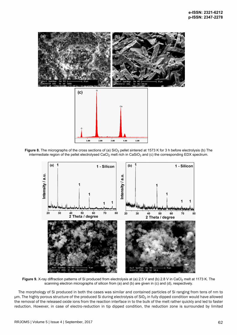
Figure 8. The micrographs of the cross sections of (a) SiO2 pellet sintered at 1573 K for 3 h before electrolysis (b) Theintermediate region of the pellet electrolysed CaCl2 melt rich in CaSiO3 and (c) the corresponding EDX spectrum.
Figure 9. X-ray diffraction patterns of Si produced from electrolysis at (a) 2.5 V and (b) 2.8 V in CaCl2 melt at 1173 K. Thescanning electron micrographs of silicon from (a) and (b) are given in (c) and (d), respectively.
The morphology of Si produced in both the cases was similar and contained particles of Si ranging from tens of nm toµm. The highly porous structure of the produced Si during electrolysis of SiO2 in fully dipped condition would have allowedthe removal of the released oxide ions from the reaction interface in to the bulk of the melt rather quickly and led to fasterreduction. However, in case of electro-reduction in tip dipped condition, the reduction zone is surrounded by limited
e-ISSN: 2321-6212p-ISSN: 2347-2278
62RRJOMS | Volume 5 | Issue 4 | September, 2017

quantity of CaCl2 electrolyte, which is facilitated by the capillary action of the melt along the pellet from the dipped tip tothe reduction zone. Therefore the released oxide ions are available in the vicinity of the reduction zone and reactchemically with the adjacent unreduced SiO2 particles in the presence of Ca2+ ions to form CaSiO3 (Ca2+ + SiO2 + O2- →CaSiO3). Since Si is highly porous and would aid easy removal of the generated oxide ions away from the reaction site inthe fully dipped condition, CaSiO3 was not observed as an intermediate product during the electrochemical reduction ofSiO2 pellets [17,19-21,23-25,27].
Current Behaviour of TiO2 and SiO2 during Electrolysis
The I-t curves obtained for electrolysis of two TiO2 pellets (weight 1.5 g each, 1.5 mm thick, 21 mm dia., sintered at1573 K for 3 h, open porosity ~20%), one configured as in Figure 1a and the other as in Figure 1b, in CaCl2 melt at aconstant applied voltage of 3.1V are shown in Figure 3. The current behaviour of a cell with SiO2 pellet in the similar twoconfigurations is given in Figure 10.
Figure 10. The variation of current with time during electro-reduction of SiO2 pellets in (a) fully dipped configuration and (b) in thetip alone contact configuration in CaCl2 melt at 1173 K. Inset shows the magnified version of beginning part of graph (b), which
shows the slow increase of current in the later case with duration of electrolysis.
The current in an electrodeoxidation cell is mainly due to the transport of the cathodically generated O2- ions and thecell current is directly related to the electroactive area of the oxide electrode. The shape of the electrolysis curves of theTiO2 electrode (a high current in the beginning which decreases with time), therefore, shows that the electroactive area ofthe oxide electrode was maximum at the start of the experiment and it decreased with time as electrolysis wascontinued. This in other words meant that the maximum area of the TiO2 pellet was electronically conducting in thebeginning of electrolysis itself. It can be seen that the current behaviour of both the cells with ‘tip dipped’ and ‘fullydipped’ TiO2 pellet cathodes is similar. This observation further shows that the oxide electrode was good conductingthroughout its body, irrespective of the location of the current lead, and followed the 2PI mechanism of reduction asdiscussed previously.
The shape of the electrolysis curves of the two cells with SiO2 pellet in the two different configurations (Figure 1a and1b), obviously, presents a different picture. Unlike the TiO2 cell, the cell current is low in the beginning of electrolysis andit slowly increased with time as electrolysis was continued. This typical current behaviour of SiO2 electro-deoxidation cellswas reported by many investigators too in the past. Obviously, the electroactive area of the electrode increased with timeduring the course of electrolysis. In the beginning of electrolysis, due to poor electronic conduction, the SiO2 pellet couldbecome electrochemically active only at those points on the electrode where the metal lead wire was in contact and theelectroactive area and hence current increased as the electro-generated silicon particles acted as electron conductingbridges to the adjoining oxide particles. The typical current behaviour of SiO2 electrode, unlike that of TiO2 electrode, is avalid proof of the need of a solid electron conductor for supplying electrons to the insulating SiO2 oxide particle at thereaction interface for its electroreduction to occur.
CONCLUSIONThe results of the novel electrochemical deoxidation experiments carried out with electrically insulating SiO2 and
electrically conducting TiO2 pellet electrodes in high-temperature CaCl2 melt, presented in this study, clearly show that
e-ISSN: 2321-6212p-ISSN: 2347-2278
63RRJOMS | Volume 5 | Issue 4 | September, 2017

the propagation of the electro-deoxidation through the solid oxide matrices and hence the physical nature of deoxidationof the two oxides are related to their electron conducting property. In the case of solid SiO2 electrode, as reported earlierby Nohira et al. [32], the reduction reaction was initiated only at those locations where the electron conducting lead metalwire was in close physical contact with the oxide electrode, showing thereby the need for co-existence of the threephysically distinct phases, viz. the solid electron conductor, the solid oxide, and the liquid electrolyte (3 PI) for deoxidationof the electrically insulating oxide to occur. However, the reduction of the tip of a TiO2 electrode, where no solid electronconductor is in contact with the oxide, clearly shows that the oxide electrode allowed passage of electrons from the metallead wire through it and thus made available electrons at the solid oxide/liquid electrolyte melt interface for thedeoxidation reaction. Obviously, two physically distinct phases, viz. the solid oxide and liquid electrolyte melt phases (2PI)were only present at the reaction interface. The 3PI mechanism, proposed to explain the electrodeoxidation of insulatingSiO2 [28,32,33], is thus demonstrated to stand reduced to 2 PI mechanism in the case of the conducting TiO2 electrode, inthis study. It is also shown here that electro-active area and hence the current of the oxide electrode, which is deoxidisedin the 2 PI mechanism (TiO2) decreases with passage of time where as the opposite happens in the case of an oxideelectrode like SiO2, which follows the 3PI mechanism of electrodeoxidation.
ACKNOWLEDGEMENTSSri Maha Vishnu D acknowledges the grant of the research fellowship from IGCAR, Department of Atomic Energy, India.
The authors sincerely acknowledge the support of Dr. G. Panneerselvam in recording the X-ray diffractograms of thesamples and Mrs. Soja K. Vijay for residual oxygen analysis of the samples. Thanks are due to Mr. V. Arun Kumar for hishelp during some of the experiments.
REFERENCES1. Fray DJ, et al. Removal of oxygen from metal oxides and solid solutions by electrolysis in a fused salt, 1999,
International patent no. WO 9964638.
2. Mohandas KS and Fray DJ. FFC Cambridge process and removal of oxygen from metal oxygen systems by molten saltelectrolysis: An overview. Trans Indian Inst Met 2004;57:579.
3. Mohandas KS. Direct electrochemical conversion of metal oxides to metal by molten salt electrolysis: a review. TransInst Min Metall C 2013;122:197.
4. Chen GZ, et al. Direct electrolytic preparation of chromium powder. Metall Mater Trans 2004;35:223.
5. Mohandas KS and Fray DJ. Novel electrochemical measurements on direct electro-deoxidation of solid TiO2 and ZrO2in molten calcium chloride medium. J Appl Electrochem. 2011;41:321-336.
6. Sri Maha Vishnu D. Studies on the molten salt electro-deoxidation of niobium, titanium, silicon and uranium oxides.Ph.D dissertation. Homi Bhabha National Institute, Mumbai, India. December 2013.
7. Sri Maha Vishnu D, et al. A study of the reaction pathways during electrochemical reduction of dense Nb2O5 pelletsin molten CaCl2 medium. Electrochim Acta 2013;100:51-62.
8. Bixia W, et al. Cathode preparation of electrochemical reduction process of TiO2 to titanium. Rare Metal Mat Eng2010;39:1513-1518.
9. Schwandt C and Fray DJ. Determination of the kinetic pathway in the electrochemical reduction of titanium dioxide inmolten calcium chloride. Electrochim Acta 2005;51:66-76.
10. Chen GZ, et al. Direct electrochemical reduction of titanium dioxide to titanium in molten calcium chloride. Nature2000;407:361-364.
11. Sri Maha Vishnu D, et al. Electrochemical reduction of TiO2 powders in molten calcium chloride. Electrochim. Acta2015;159:124-130.
12. Yan XY, Fray DJ. Production of niobium powder by direct electrochemical reduction of solid Nb2O5 in a eutectic CaCl2-NaCl melt. Metall Mater Trans B 2002;33B:685-693.
13. Sri Maha Vishnu D, et al. Electrochemical conversion of solid Nb2O5 to Nb in sodium chloride melt as proof of oxygenionisation mechanism of electrodeoxidation. J Alloys Compd 2016;677:258-265.
14. Sri Maha Vishnu D, et al. Mechanism of direct electrochemical reduction of solid UO2 to uranium metal in CaCl2-48mol% NaCl melt. J Electrochem Soc 2013;160:D394-D402.
15. Sri Maha Vishnu D, et al. Determination of the extent of reduction of dense UO2 cathodes from directelectrochemical reduction studies in molten chloride medium. J Nucl Mater 2012;427:200-208.
e-ISSN: 2321-6212p-ISSN: 2347-2278
64RRJOMS | Volume 5 | Issue 4 | September, 2017

16. Sri Maha Vishnu D, et al. Factors influencing the direct electrochemical reduction of UO2 pellets to uranium metal inCaCl2-48 mol% NaCl melt. J Electrochem Soc 2013;160:D583-D592.
17. Yasuda K, et al. Mechanism of direct electrolytic reduction of solid SiO2 to Si in molten CaCl2. J Electrochem Soc2005;152:D69-D74.
18. Yasuda K, et al. Diagrammatic representation of direct electrolytic reduction of SiO2 in molten CaCl2. J ElectrochemSoc 2007;154:95-101.
19. Yasuda K, et al. Electrolytic reduction of a powder-molded SiO2 pellet in molten CaCl2 and acceleration of reductionby Si addition to the pellet. J Electrochem Soc 2005;152:D232-D237.
20. Nishimura Y, et al. Formation of Si nanowires by direct electrolytic reduction of porous SiO2 pellets in molten CaCl2. JElectrochem Soc 2011;158:E55-E59.
21. Cho SK, et al. Formation of a silicon layer by electroreduction of SiO2 nanoparticles in CaCl2 molten salt. ElectrochimActa 2012;65:57-63.
22. Xiao W, et al. Rationalisation and optimisation of solid state electro-reduction of SiO2 to Si in molten CaCl2 inaccordance with dynamic three-phase interlines based voltammetry. J Electroanal Chem 2010;639:130-140.
23. Nohira T, et al. Pinpoint and bulk electrochemical reduction of insulating silicon dioxide to silicon. Nat Mater2003;2:397-401.
24. Ergul E, et al. Electrochemical decomposition of SiO2 pellets to form silicon in molten salts. J Alloy Compd2011;509:899-903.
25. Yasuda K, et al. Effect of electrolysis potential on reduction of solid silicon dioxide in molten CaCl2. J. Phys ChemSolids 2005;66:443-447.
26. Jin X, et al. Electrochemical preparation of silicon and its alloys from solid oxides in molten calcium chloride AngewChem 2004;116:751-754.
27. Yasuda K, et al. Direct electrolytic reduction of solid SiO2 in molten CaCl2 for the production of solar grade silicon.Electrochim Acta 2007;53:106-110.
28. Chen GZ, et al. Direct electrolytic preparation of chromium powder. Metall Mater Trans B 2004;35B:223-233.
29. Xiao W and Wang D. The electrochemical reduction processes of solid compounds in high temperature molten salts.Chem Soc Rev 2014;43:3215-3228.
30. Xiao W, et al. Electrochemically driven three-phase interlines into insulator compounds: Electroreduction of solidSiO2 in molten CaCl2. Chem Phys Chem 2006;7:1750-1758.
31. Jin XB, et al. Electrochemical preparation of silicon and its alloys from solid oxides in molten calcium chloride. AngewChem Int Ed 2004;43:733-736.
32. Deng Y, et al. Electrochemistry at conductor/insulator/electrolyte three-phase interlines: A thin layer model. J PhysChem B 2005;109:14043-14051.
33. Wang D, et al. Solid state reactions: an electrochemical approach in molten salts. Annu Rep Prog Chem Sect C2008;104:189-234.
34. Massalski TB. Ti-O phase diagram. In: Massalski TB. Binary alloy phase diagrams (2nd edn). ASM Int 1990;3:2941.
35. Song HS, et al. Effect of microstructural features on the electrical properties of TiO2. Mat Sci Eng 2002;B94:40-47.
36. Bak T, et al. Electronic and ionic conductivity of CaTiO3. Ionics 2004;10:334-342.
37. Okamoto H. O-Si phase diagram. J Phase Equilib Diff 2007;28:309-310.
38. Srivastava JK, et al. Electrical conductivity of silicon dioxide thermally grown on silicon. J Electrochem Soc1985;132:955-963.
e-ISSN: 2321-6212p-ISSN: 2347-2278
65RRJOMS | Volume 5 | Issue 4 | September, 2017