research on the flammability characteristics of … · three ignition sources superimposed on the...
TRANSCRIPT

%AVC TECHNICAL REPORT 52-35 ._
AFMPDVED FOR PUBLIC RML&Ajý
DISTRIBUTIONUNLIMI.Trk
RESEARCH ON THE FLAMMABILITY CHARACTERISTICS OF AIRCRAFT FUELS
G. W. JONES
M. G. ZABETAKIS
J. K. R!CIIMOND
G. .5. SCOTT
A. L. FURNO
LUNITED STATES DEPARTMENT OF THE INTERIOR
JIUNE 1952
Reproduced FromBest Available Copy
WRIGHT AIR DEVELOPMENT CENTER
,!L\~
//4
TADC TECHNICAL REPORT 52-35
RESEARCH ON THE FLAMMABILITY CHARACTERISTICS OF AIRCRAFT FUELS
G. W. JonesM. G. Zabetakis
K. K. RichmondG. S. Scott
A. L. Furno
United States Department of t~e Interior
June 1952
Materials LaboratoryContract No. AF 33(038) 50-1293E
RDO No. 601-301
Wright Air Development Center
Air Research and Development CommandUnited States Air Force
Wright-Patterson Air Force Base, Ohio
McGregor & Wernet. Dayton, 0.250 Mach, 1953

TOPU.EORD
This report was prepared by the Gaseous Explosions Branch, Explosivesand Physical Sciences Division of the U. S. Bureau of Mines on ContractNumber ,F 3J(038) 50-1293E, RDO No. b60-301, Aircrart Fuels and EngineOils. This project. was initiated at the Bureau of Mines under Air MaterielCommand supervision and completed under Wright Air Deve)opment Centersupervision. It wao administered under the direction of Mr. R. W. Alt.nand Capt C. M. Murray of Materials Laboratory, Directorate of Research, WADC.Drs. Bernard Lewis and Glenn H. Damon were the administrators for the U. S.Bureau of Mines. Mr. G. W. Jones was project engineer. Messrs. G. W.Jones, M. G. Zabetakis, J. K. Richmond, G. S. Scott, and A. L. Furno werethe authors of this report.
Those who were engaged in the experimentai work for this projectincluded Messrs. G. W. Jones, M. G. Zabetakis, J. K. Richmond, A. L. Furno,G. S. Scott, and F. E. Donath.
W-DC TR 52-35

ABSTRACT
The results of limit of flammability, limit of ignitibility, andignition temperature tests conducted on aircraft fuel vapor-air mix-tures by the U. S. Bureau of Mines Gaseous Explosions Laboratorybetween February 19, 1950 and February 19, 1952 are presented. Twoaviation gasolines grades 10O/130 and 115/145, and two jet fuels gradesJP-l and JP-3, were inve3tigated. A limited amount of work was done onthe ignitibility of JP-1 mists and sprays, and on the ignition tempera-tures of aircraft hydraulic fluid AN-O-366.
In addition to the above results, sections are included on defini-tions and theory, and apparatus used for the investigation is described.
PUBLICATION APPROVAL
Tkis report has been reviewed and is approved.
FOR THE COMMANDING GENERAL:
Colonel, USAIr
Chief, Materials LaboratoryDirectorate of Research
i5iWADC TR 52-35

TABLE OF CONTUNTSPage
SECTION I Purpose of the PrcjecL i------------------1
SECTION 1I Defin'tions and Theory- ----------- 5
2.1 Flammable Gaseous Mixture- --------- 5
2.2 Nonflammable Gaseous Mixture ----- 5 -i
2.3 Limit Mixture-- ----------------- 5
2.4 Concentration Limits of Flammability - - - 5
2.5 Limits of Ignitibility- ----------- 7
2.6 Temperature or Equilibrium ConcentrationLimits of Flammability- ----------- 7
2.7 Low Pressure Limit of Flammability -l- - - -- 11
2.8 Spontaneous Ignition Temperature and theCorresponding Time Lag Before Ignition - - - 11
2.9 Minimum Spontaneous Ignition Temperature - - 1]
2.]0 Flammability Characteristics of CombustibleGases and Vapors - ---- - --- -- --- --- i
2.11 Combustion of Flammable Mixtures -------- 14
2.12 Mists and Sprays ------------------ ----- 17
SECTION III Experimental Results ---------------- --- 19
3.2 Limits of Flammability ------ --------- 19
3.3 Spark Ignition Energy Measurements ------ 32
3.4 Ignition Temperatures ------------------- 39
3.5 Sprays and Mists -O--------------- ------- 40
SECTION IV Proposed Future Investigations ---------- 46
SECTION V Conclusions --------- ----------------- 47
iv
WADC TR 52-35

TABL& OF CONTENTS (Cont ' d.)
BIBLI OGRAPHY 49
APPENDIX I The F-I LLmit-of-Flam.aDiiity Apparatus ---------- 52
jiPPENDIX II The I-8 Ignition Temperature Apparatus------ 54
ireENDIX III The F-9 Lindt-of-Flammahility Apparatus 56
.rifENDIX IV The F-l0 Limit-of-Flavmmability Apparatus - - - 59
AkPEN-DIX V The F-il Limit-of-Flammability Apparatus --- 59
APPENDIX VI The F-12 Limit-of-Flammability Apparatus - 73
APPENDIX VII The F-21 Lirmit-of-Flammability Apparatus 73
APPENDIX VIII The F-24 Limit-of-Flammability Apparatus 74
APPENDIX IX Spray ind Mist Apparatus- - ----------- 74
APPENDIX X Ignition Sources- - --------------- 80
INDEX -------------------------------- -------- 90
INITIAL DISTRIBUTION LIST-- ----------------- 93
v
WADC TR 52-35

LIST OF ILLJSTRATIONS
FIGURE Ple
. A.S.T.M. distillaition curves for (a) aviation gasolinegrade 100/130, (b) aviation gasciine grade 115/145,(c) aviation jet fuel grade JP-i, and (d) aviation jetfuel grade JP-3----------------------- ------------ 2
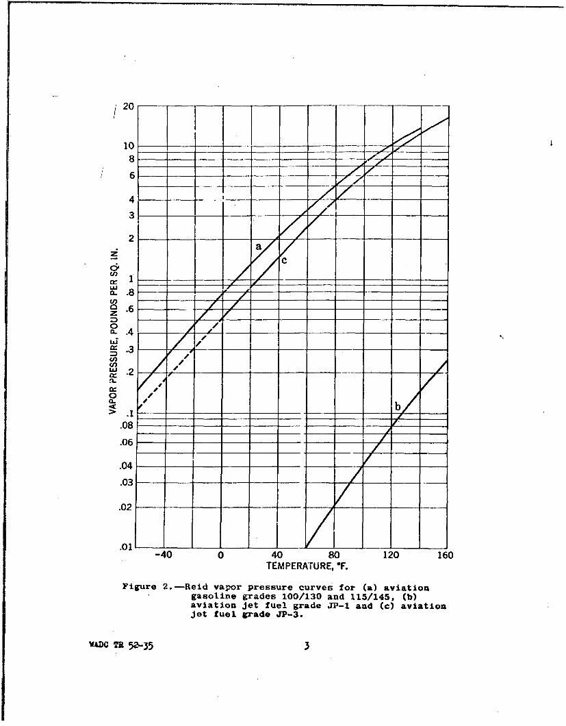
2. Reid vapor pressure curves for (a) aviation gasolinegrades 100/130 and 115/145, (b) aviation jet fuel gradeJP-1, and (c) aviation jet fuel grade JP-3----------3
3. Ignitibility curve for but.ane-air rrixt'ires at oneatmosphere and 780F.--------------------------------8
4. General form of limit-of-flammability curves atconstant pressure----------------------------------- 9
5. General form of temperature lidts of flammabilitycur've for uquilibrium (saturated) vapor-air mixtures - - 10
6. A general flaimmable volume of a combustible vapor-airmixture -'----------------------------------------13
7. Comparison of the variations in the concentration limitsof flammability of six hydrocarbons with temperature forone atmosphere pressure using (a) units of volume, (b)units of weight to express the lower limit concentrations 15
8a. Concentration limits of flammability for aviationgasoline grade 100/130 vapor-air mixtures at 78 ± 10 F. - 20
8b. Concentration limits of flammability for aviation gaso-line grade 100/130 vapor-air mixtures at 78 ± 10 F. (curveobtained from Figure 8a taking average molecular weightof this fuel to be 100) ----------------------------- 21
9a. Concentration limits of flammability for aviation gaso-line grade 115/145 vapor-air mixtures at 78 ± 2-F. --- 22
9b. Concentration limits of flammability for aviation gaso-line grade 115/145 vapor-air mixtures at 78 ± 20 F.(curveobtained from Figure 9a taking average molecular weightof this fuel to be 100). ---------------------------- 23
lea. Concentration limits of flammability for aviation jetfuel grade JP-3 vapor-air mixtures at 79 ± 20F. 24
lOb. Concentration limits of flammability for aviation jetfuel grade JP-3 vapor-air mixtures at 79 ± 20F. (curveobtained from Figure lOa taking average molecular weightof this fuel to he 100) ----------------------------- 25
viWADC TR 52-35

TI LJUSTRaTIONS (Cont'd.)
II. Epiuilibriuir concentration llmits of fli ability of the0 to 5% fracticn of aviatior pmoline grade 100/130vapor-air mixtures over the -, mý.-rature range -100 toOFo (the 0 to 5% fraction of L.>:u fuel was distilledunder the terperature and pressur, conditions of eachtest ) --------------------------------------------- 28
12. Equilibriun concentration linidti of flammability of the0 to 10% fraction of aviation rasoline grade 115/145vapor-air mixtures over the tu.:n' rature range -100 toO°F. (the 0 to 10%, fraction of this fuel was distilledunder the temperature and pressure conditions of eachtest).--------------------------- 2
13. Equilibrium ccncentration limits of flamrn•bility of the0 to 30% and 60 to 90% fractions of aviation jet fuelgrade JP-! vapor-air mixtures over the temperaturc range60 to 200 0 F. (the 0 to 30 and 60 to 90% fractions cfthis fuel were distilled under the temperature and -res-sure conditions of each test). ---------------------- 30
14. Equilibrium concentration lirdts of flaritraility of' the 0to 5% and 80 to 90% fractions of aviation jet fuel gradeiJP-3 vapor-air mixtures over the temperature range -10Yto +2003F. (the 0 to 5% and 80 to 90% fractions of thisfuel were distilled under the temperature and pressureconditions of each test). --------------------------- 31
15. Oscillcgra-,s of the (a) voltage across and (b) currentthrough a spark discharge gap in an aviation gasolinegr-de I15/hf vapor-air mixture at -73 0 F. and 27 inchesHg absolute. (See Figure 16 for the analysis of theseoscillograms ------------------ ------------------- 34
16. Andlysis of odilllograms 551-3 and 551-4 given inFigures 15a and 15b -------------------------------- 35
17. Limits of ignitibIlity of aviation gasoline grade 115/145vapor-air mixtures at low temperatures and pressures forthree ignition sources superimposed on the equilibriumconcentration limit-of-flaminability curves for the 0 to10%fractlonof the fuel ---------------------------- 36
18. Low pressure ignitibility curves (minimum pressure atwhich ignition occurs plotted as a function of -,parkenergy and time duration) for the cdncentrationi of avia-tion gasoline grade 100/130 vapor in air noted on eachset of graphs --------------------------------------- --37
viiWýDC TR 52-35

ILLUSTR4JTIONS (Cont 'd.)
FIGURE Page•Q LOW prsue 44 .... t, 4•.:.' 1'i-cuvs'
S Lowp'ere . .l.y (minimum pressure atwhich ignition occurs, plotted as a function of sparkenergy) for different concentrations of aviation gaso-line grade 100/130 vapor-air mixtures and for twoelectrode configurations. Duration of sparks is between500 and 2500 microseconds -------------------------- 38
20. Variations in spontaneous tion tcmpcratures -withtime lag before explosion and quantity of combustiblefor, (a) aviation jet fuel grade JP-I, (b) aviation jetfuel grade JP-3 and, (c) aircraft hydraulic fluidAi-0-366 in contact with magnesium (FS-I, Spec. QQ.-M, 44)in air at atmospheric pressure. - ------------- 41
21, Lines of equi-ignition probability for aviation jet fuelgrade JP-1 spray in air using powerful sparx ignitionsource (30-50 watts). - - - - - -- -- -- -- -- -- -- -- -- -- -- - -- 42
22. Total air velocities due to the primary air from a two-fluid nozzle plus the entrained secondary air for threeexit chambers attached to the nozzle, (large circlesrepresent chamber outlets, n': hers in small circles arevelocities in hundreds of fe- 'zer minute) - - - - - -- -- 44
23. Photomicrographs of impressi .made on a carbon coatedmicroscope slide by aviation .t fuel grade JP-l sprayformed with a two-fluid nozzl .-- ----------- 45
24. Schematic diagram of the F-1 -. -it-of-flammabilityapparatus . ----------------------------------------- 53
25. Detailed drawirg of the 1-8 ignition temperatureapparatus. ----------------------------------------- 55
26. Schematic diagram of the F-9 elevated temperature equi-librium concentration lLdit-of-flammability apparatus. - 57
27. Close-up view of the F-9 and F-11 explosion chambersinstalled in the oven.- ---------------------------- 58
28. Schematic diagram of the F-10 limit-of-flammability
apparatus. -- ----------------------------------- 60
e9.• Ceneral view of the F-10 limit-of-flamnmability apparatus. 61
30. Close-up view of the F-lO explosion chamber installed inthe C02 cold chamber. ------------------------------- 62
viii
W&DC TR 52-35
ILLUSTRATIONS (Cont'd.)FIGURE Page
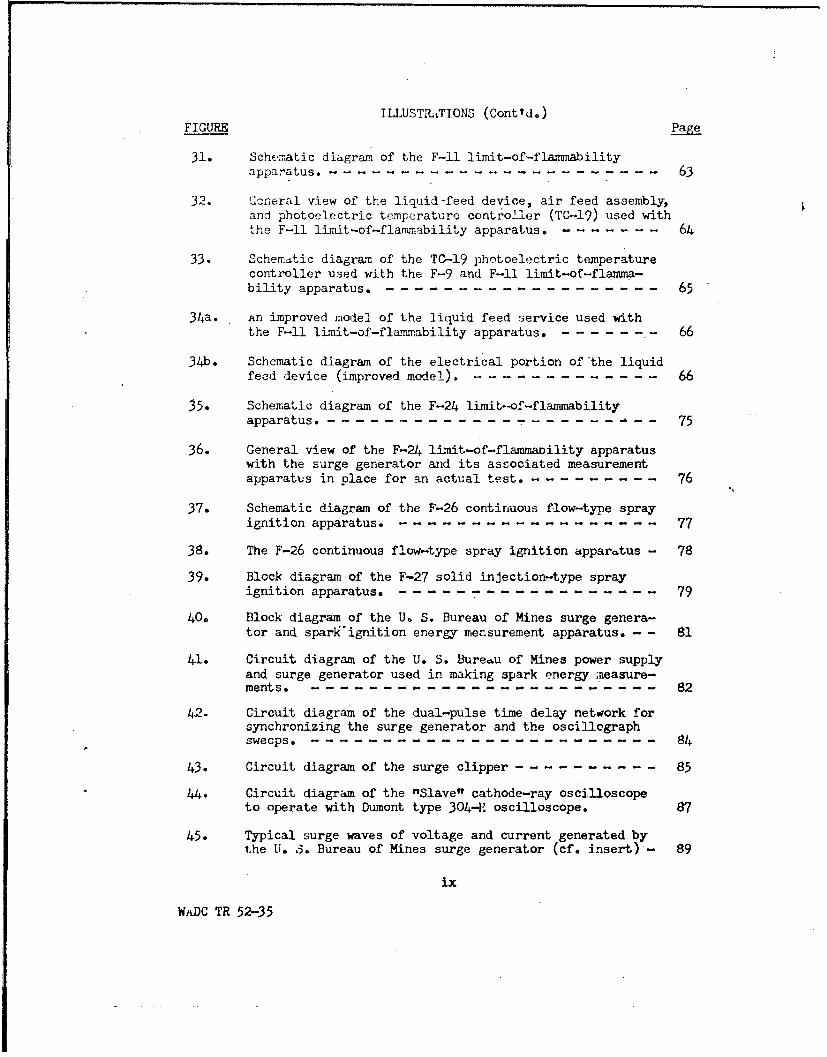
31. Schematic diagram of the F-il limit-of-flaimiabilityapparatus ------------------ --------------------- 63
32. Ucneral view of tbe liquid-feed device, air feed assembly,and photoelectric temperature controller (TC-19) used withthe F-i1 limit-of-flammability apparatus.,-------- 64
33. Schema-tic diagram of the TC-19 photoelectric temperaturecontroller used with the F-9 and F-li limit-of-flamma-bility apparatus. ---------------------------------- 65
34a. An improved model of the liquid feed service used withthe F-il limit-of-fla'Tnability apparatus.------- --- 66
34b. Schematic diagram of the electrical portion of the liquidfeed device (improved model). ---------------------- 66
35. Schematic diagram of the F-24 limit-of-flammabilityapparatus. - - ------------ --- ---- - - 75
36. General view of the F-24 limit-of-flammaDility apparatuswith the surge generator and its associated measurementapparatus in place for an actual test. -------------- 76
37. Schematic diagram of the F-26 continuous flow-type spray
ignition apparatus. --------------------------------- 77
38. The F-26 continuous flow-type spray ignition apparatus - 78
39. Block diagram of the F-27 solid injection-type sprayignition apparatus. --------------------------------- 79
40, Block diagram of the U* S. Bureau of Mines surge genera-tor and sparktignition energy measurement apparatus. - - 81
41. Circuit diagram of the U. S. Bureau of Mines power supplyand surge generator used in making spark energy neasure-ments - -------------------------------------------- 82
42. Circuit diagram of the dual-pulse time delay network forsynchronizing the surge generator and the oscillographsweeps.------------------------- 84
43. Circuit diagram of the surge clipper ---------------- 85
44. Circuit diagram of the "Slave" cathode-ray oscilloscopeto operate with Dumont type 304-F oscilloscope. 87
45. Typical surge waves of voltage and current generated bythe U. 3. Bureau of Mines surge generator (cf. insert) - 89
ix
WADC TR 52-35

INTRODUCTION
The limits of flahmability of various con'bustible-air mixtures havebeen the subject of extensive research. }{ow~-v•r, few investigators haveconsidered limits of flammability at redu -- inperatures and pressures.As high altitude flying involves explosion risks from combustible-airmixtures, the Wright Air Development Center has been led to initiate aprogram for the investigation of fire and explosion hazards in aircraft.Information obtained from experiments and literature surveys in thecourse of this investigation indicate a great need for a eystematicresearch program on various flammability characteristics of aircraft fuels.The work reported here is an outgrowth of the original WADC investigation.
x
WADC TR 52-35

SECTION I
PURPOSE OP THE PROJECT
1.1 The present project involves the determination of various flamma-bility characterist!ics of aircraft fuels under flight conditions. Itspurpose may be determined best by ccnsidering the program undertaken andthe fuels studied.
1.2 Program
1.2.1 The program for the study of flammability characteristics of air-craft fuels may be separated into two phases.
i....2 PHASE 1: (1) Determine the limits of flammability of various USAFfuels over the temperature range -10" to +1600F. and the prcssure range 1to 30 inches merzury (Hg). (2) Determine how the energy of the spark &ndthe material, size and shape of Lý spark electrodes affect the limits ofignitibility at various temperatuinb (--100 to 1600F.) and pressures (1 to30 inches Hg). (3) Study the effe.L of the type and strength of the igni.-tion source (spark, hot wire , guncrtton, etc.) on the lii,-ts of ignitibilityat low pressures with the view of establishing the low pressure limit offlammability.
1.2.3 PHASE 2: (1) Using a f-1 :.';em, determine the limits of igniti-bility (expressed as a fuel-ai La'" as a function of tcnperature,pressure and zixture velocity of varao:- •JSAF fuel vapor-air mixtures.The ignition source should be a continuous spark or heated element of vary-ing size, shape and material, as specified by the contractor. If aheated element is used, the contact time between the combustible mixtureand the heatei element should be determined in all cases. (2) Using aflow system, determine the effect of various USAF fuel spray patterns andfuel droplet size ranges on the limits of ignitibility under the conditionsoutlined above. (3) Investigate the flammability characteristics ofvarious USAF fuel components.
1.3 Fuels
1.3.1 The following USAF fuels were used in this investigation:
(1) Aviation gasoline, grade 100/130(2) Aviation gasoline, grade 115/145(3) Aviation jet fuel, grade JP-1(4) Aviation jet fuel, grade JP-3
In addition, a limited amount of work was performed on (5) aircrafthydraulic fluid AN-o-366 . The ASTM distillation and vapor pressure curvesof the above fuels are given in Figures 1 and 2. The data for these
WADC TR 52-35

/
460 -i
420 - A_-
I _/
7
I
I- -- - - - - --- - - - - - - - -
2U 26 I A-+- 71----------
180 -- -" -
--- liid-140/
100 110 20 - 40 60 80 100
DISTILLED, PERCENT
Figure l.-A.S.T.M. dtistillation curvoc for (a)aviatioai gasoline grade 100/130,(b) aviation gasoline grade 115/145,(c) aviation jet fuel grade JP-1,and (d) aviation jet fuel grade JP-3.
VADC TR 52-35 2
8 _
6
3
Cl)
0
LAY
0)
.06
.08
.06 _ __ _
-40 0 40 80 120 160TEMPERATURE, T.
Figure 2.-Reid vapor pressure curves for (a) aviationgasoline grades 100/130 and 115/145, (b)aviation jet fuel grade JP-1 and (c) aviationjet fuel grad. JP-3.
V.&DO TR 52-35 3
curves were obtained from WADCo. The dashed portion of curve C in Figure2 i:3 not part of the W.iDC data, but is -n extrapolation of the datalying above OOF. This extrapolation was made in ord-er to account forthe explosive saturated JP-3 vapor.-ilr mixtures which exist below -4O0 F.(t.emperature below which no explosions s-ould occur according to theoriginal WADC data). The specifications for the above fuels and thehydraulic fluid are covered in Specifications MIL-F-5572, MIL-F-5624A,MIL-F-5616 and MIL-O-5606.
4WADC TR 52-35

SECTION II
DEFINITIONS AND THEORY
2.1 Flarmable Gaseous Mixture
2.1.1 A "flanunable gaseous mnixture" is a t'e of gases through which
flame is capable of propagating.
2.2 Nonflanmable Gaseous Mixture
2.2.1 A "nonflammable gaseous mixture" is a mixture of gases throughwhich flame fails to propagate.
2.3 Limit Mixture
2.3.1 A mixture of gases whose composition lies in the transition regionbetween mixture compositions corresponding to flammable and nonflammablemixtures may be loosely termed a "flimit mixture." A flammable mixturemay be rendered apparently, or perhaps truly, nonflammable by a change inone or more of the following factors associated with the mixture or itssurroundings: (Ref. 38)
(1) Tenperature(2) Pressure(3) Ratio of combustible to oxygen(4) Ratio of inert or other foreign
gas to oxygen(5) Characteristics of the ignition source(6) Geometry and size of the confining vessel(7) Physical state and surroundings of the
gaseous mixture
It should be noted thaL even though a suitable change in any one of theabove factors may render a flammable mixture nonflammable, the converseis not necessarily true. The above factors are interrelated in such amanner that before deciding whether or not a mixture is truly nonflammablean observer should determine the effects of each of these factors on hisobservations. This point will be discussed more fully in the followingsections.
2.4 Concentration Limits of Flammability
2.4.1 As the combustible mixtures considered in this report were composedof combustible vapors and air, the ratio of inert or other foreign gas tooxygen (4) will be considered constant for all mixtures discussed. Ifin addition to (4) all items except (3) are held constant while (3) isvaried for a flammable mixture by diluting the mixture with air, the com-bustible content of the flammable mixture eventually becomesso low that the
5
WALDC TR 52-35

mixture fails to propagate flame. If at this point a number of similartests are made in which (5), (6) and (7) are also varied, the gaseousmixture being homogeneous and quiescent dLuring the period of applicationof the ignition source as well as the subsequent period of observation,the lowest concentration of combustible in air at a particular temperatureand pressure that is capanle of propagating flane through a homogeneousquiescent mixture of the combustible and air being tested may be expressedas:
t = 1/2 LCf1 + C,8g] ()
2.4.2 Similarly, if - flammable gaseous mixture is rendered nonflammableby the addition of an excess of combustible, the upper limit of flamnma-bility may be expressed as:
Utp = 1/2 LCfg + COnj (2)
Lts and Ut, , being respectively the lower and upper concentration limitsof' lammabi ity at a specified temperature and pressure; Cng and Cnl arethe greatest and least concentrations of combustible in air which are N.nonflammable, and Cfl and Cfg are the least and greatest concentrations ofcombustible in air which are flammable at the specified temperature andpressure of the test.
2.4.3 The concentration limits of fla-bmability are conventionally termedlimits of flatniability, limits of inflammability, flammable (or inflammable)limits, or explosive limits. These terms are considered synonymous.
2.4.4 An important experimental criterion in determining the limits offlammability of a particular combustible vapor or gas in air at a specified"temperature and pressure is the following: The limits of flammability ofany combustible are widened - that, is, the lower limit is decreased andthe upper limit is increased - with moderate increases in temperature andpressure. As most ignition sources instantaneously increase both thetemperature and pressure in their immediate vicinity, in going from aflammable to a nonflammable mixture at a specified temperature and prcssure,there must be a small range of concentrations (the transition region) thatare able tu propagate flame a short distance away from the ignition sourcedue to the instantaneous increase in temperature and pressure. However,these mixtures will not propagate flame once the effects oC the ignitionsource are no longer felt. If thi3 transition region is not observed,then the limits of flammability have probably not been attained; instead,these apparent limits are merely limits of ignitibility or ignition limitsthat depend on the ignition source and are therefore not a function of thecombustible, temperature and pressure alone as are the limits of flamma-bility.
6
WiADC TR 52-!3,5

/
2.5 Limits of Ignitibility
2.5.1 The lifits of ignitibility have been briefly defined in paragraph2.4.1. A better way of visualizing the relationship between the limits ofignitibility arnd the true 1Lmits of flammability is to plot the limits ofignitibility as a function of the ignition ',ovzce energy. To be consistentlet us assume that the source energy is delivered as a single square wavepulse whose duration is the same in each case, that is, we will assumethe time of delivery of the ignition energy to be constant. If we thenplot the limit of ignitibility as abscissa against the energy of theignition source as ordinate, we obtain a curve such as that in Figure 3-(refs. 3 and 7). The actual shape of the curve is noL important here.The irportant thing is that for a certain optilmum range of ignition sourceenergies (and an associated range of time durations for delivery of theenergyto the test mixture) the limits of ignitibility depend only on thecombustible tested (assuming the temperature and pressure to be constant).This means that the imporant experimental criterion described in paragraph2.4.4 is applicable. Thus These unique limits of ignitibility are, bydefinition, the limits of flammability of the matcrial tested at thetemperature and pressure specified for the test.
2.6 Temperature or Equilibrium Concentration Limits of Flammability
2.6.1 If the temperature of a flammable mixture corresponding to the upperlimit of flammability is gradually decreased while the pressure is heldconstant, a temperature is finally reached such that the upper limit offlammability coincides with the dew point of the combustible (or of oneof its constituents in the case of a mixture of cvuL~stibles). Thistemperature is the upper temperature limit of flammability at the constantpressure specified for the test. If the temperature is decreased further,all concentrations lying on the equilibrium vapor--air curve (dew-pointcurve) represent flamaeole mixtures until a point is reached on this curvethat coincides with the lower limit of flammability at that temperatureand pressure. This temperature represents the lower temperature limit offlammability; it also corresponds roughly to the flash point of thecombustible if the pressure is one atmosphere. (If the U. S. Bureau ofMines F-9 apparatus is used, the lower temperature limit at atmosphericpressure could be defined as the flash poinb). The vapor concentrationfor temperatures below the lower temperature limit of flammability is toolow (at the specified constant pressure of the tests considered) to givean explosive limit (Figure 4). CGviously the lower temperature limit willdecrease for a moderate decrease in pressure (Figure 5).
2.6.2 It should be noted also, in conjunction with the temperature limitsof flammability (Figure 5), that these limits may be converted to concen--tration limits when the vapor pressure of the combustible is known as afunction of temperature.
7
WADC TR 52-35

1,0 ;I i800 EE--~600 __H zzizz4 -z
400--- Limits of flammabiliyz 300--/Lh 1 ~
t- 200--_I
80S 80 __ _ ..... 1-g,5 60 i _ -. _
z 40 --- - I ,C,) 30 ' ' - -
0 20 . .. .I(n J Limits of ignitibility -- J
108
.• 4-, _ Fz 3
< 0.6 :\Iw I
03 - I
S0.4 j--_70.3~
0.20 0.04 0.08 0.12 0.16 0.20LIMITS OF IGNITIBILITY AND OF FLAMMABILITY
IN RATIOS OF WEIGHTS OF BUTANE TO AiR, F/A
Figure 3. - Ignitabitity curve for butane-air mixturesat one atmosphere and 78° F.
wfDC Th 52-35 8

-/-Mixtures -Stoo rich
to propagate -00
3 Mixtures Flammable -- --<. too mixtures
,,, -lean to -- ,_p ropagate" flame j--- - Equilibrium vapor-air curve
(dew point curve) l
Impossible
--- m ixtures
S "Flash point (U.S. B. M. apparatus)
-% COMBUSTIBLE VAPOR IN A VAPOR AIR MIXTURE AT ONEAIMOSPHERE PRESSURE
Figure 4.- General form of limit of flammability curves at constant pressure.
WAXC T' 52-35 9

I AI
• One atmosphere 0
_ __ _ _ - I -
- Mixtures too lean__ Flammable M ixtures too rich,. to propagate flame/ mixtures t. propagate flame
- ___ ~~Low temperature limit of flammability__- _
1. Flash pit(U.S. B.M. aprts___ I-
j
TEMPERATURE OF SATURATED COMBUSTIBLE VAPOR-AIR MIXTUREFigure 5. - General form of temperature limits of flammability curve for
equilibrium (saturated) vapor-air mixtures.
.AD Ta k 52-10 1

2.6.3 The limits discussed above refer only to vapor-air mixtures. Itshould not be assumed that an explosion hazard does not exist at tempera-tures below the lower temperature limit of flammnability, as finely divideddroplets of combustible liquid may form sprAys at temperatures below thelower temperature limit. In such cases the problem is complicated in thatthe vapor pressure then is also a fanction of the droplet size; moreoverto determdne whether the vapor-air mixture surrounding any particulardroplet is exploeive or nrzo ue need to knjow th-pttranqSrPi rni.e fro-mthe surroundings to the droplet and the vaporization rate of the droplet.As all available data indicate that the burning process associated withcombustible liquids occurs in the vapor state, the problem of flammablesprays appea.rs to be an extension of the burning of vapor-air mixtures.
2.7 Low Pressure Limit of Flanmability
2.7.1 No mention has been made yet of the lowest pressure at which aflammable mixture can propagate flame. This lowest pressure could perhapsbe considered the region where the lower limit meets the upper limit offla.mability. It is in general very difficult uo get a satiafactoryignition source for experiments in this low pressure region (especially forpressures below about one inch Hg absolute). In many experiments thecriterion for determining the true limits of flammability, as outlined inparagraph 2.4.4.,is not attained. When this criterion has not been metthe experiments yield limits of ignitibility; this is indicated when itoccurs in the figures included in this report by a broken line and anappropriate label (e.g., cf. Figures 8a-1b).
2.8 Spontaneous Ignition Temperature and Corresponding Timt Lag BeforeIgnition
2.8.1 The spontaneous ignition temperature at a specified pressure of aparticular combustible-air mixture in contact with a specified surface isthe temperature at which this mixture will ignite spontaneously in afinite time interval t, the corresponding time lag before ignition.
2.9 Minimum Spontaneous Ignition Temperature
2.9.1 At a specified pressure of a combustible in contact with a specifiedsurface, the minimum spontaneous ignition temperature for all possibleconcentrations of combustible in air that corresponds to some finite timelag sufficiently long to assure a minimum value of ignition temperature isknown as the minimum ignition temperature of the combustible in air. Thisminimum temperature depends on the surroundings and their geometry as wellas on the history of the combustible-air mixtures tested, and on thevelocity of the mixture tested.
2.10 Flasnabiljly Characteristics of Combustible Gases and Vaprs
2.10.1 PURE LIQUIDS. The limits of flammability and spontaneous ignitiontemperatures (S.I.T.) corresponding to a time-lag long enough to give the
31
WADC TR 52-35

lowest S.I.T. for a particular mixture, pressure and surface, constifutethe flammability characteristics of a combustible gas or vapor. Experi-mentally we obtain temperature limits of flammability as a function ofpressure, concentration limits of flammability as a fusi-tion of temperature,and also as a functijn of pressure (Figures 4 and 5) and spontaneousignition temperatures as a function of concentration for a fixed surface,pressure; and tMme lg. All these values may be r)lotted on a three-dimensional coordinate system with c-lccritration, pressure, and tempuratureat the three variables. If the limits of flaLmnability are plotted in thisspace, there results a flauLmable volume as in Figure 6. Mixtures in thisvolume are flatymable when an appropriate ignition source is used. Forelevated temperatures and a specified sarface, pressure and composition,spontaneous ignition results if the time of contact between the heatedsurface and the combustible mixture is greater than a ce tain specifiedtime interval. For completeness this S.I.T. curve has been included inFigure 6 for one atmosphere pressure.
2.10.2 LIQUID MIXTURES. As actual aircrait fuels consist of mixtures ofcombastibles we will digress at this point to consider the effects of thesemixtures on the over-all picture of the flannability characteristics of thefuels. Everj-thing discussed to this point applies to pure liquids as wellas mixtures of pure liquids, however when working with miLxtures the flamma-bility characteristics may vary considerably depending on the history ofthe mixture. The fuel mixtures we will consider are actually solutionscomposed of a large number of hydrocarbons.
2.10.3 The vapor pressure at equilibrium of any comiponent of the hydro-carbon mixtures that mare up the aircraft fuels considered here may bedetermined for the vapor above the liquid in a closed container by Raoult'sLaw: (Ref. 19)
Px nO~ )
> nss=1
where px and px0 are the partial pressure and vapor pressure respectivelyof component x; nx and n. are the number of moles of components x and srespectively. Thus, if we know the mole fraction of each hydrocarbonconstituent in a fuel we can determine its limits of flammability in aclosed container at any temperature, assuming that the limits of flammabilityand vapor pressure of each constituent at that temperature are known bymeans of LeChatelierls Law, which has been shown to hold quite well formany hydrocarbons. (Ref. 8) For example, the lower limit would be:
Lt~ 100 (4)
n .Lt ,p
12WADC TR 52-35.
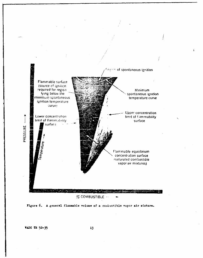
I r r~' of spontaneous ignition
Flammable surface-(source c~f Igriticn
!equired for regioa Mt U Mr rlying below the 'spontaneous ignition
minimum. spontaneous ') iitemperature curveignition temperature
Lowe conentator ~-Upper concentrationLowe conentrtionlimit of f ammability
limit of flamrn)[:iLjity surface3surfac.
Cd)
Vd)
4) Flammable equiiibriumIS concentration surface
isaturated combustiblevapor air mixtures)
%COMBUSTIBLE
Figuxre 6. A general flammable volume of a combusti~ble ra-por air mixture.
VADC TR 52-35 13

where
= lower limit of the mixture at the specifiedtemperature and press.re,
Lnt = lower limit of the nth component at the specifiedtemperature and pressure,
Pn = percentage by volume of the nth component inthe vapor-air mixture investigated
SPn = ?00 percent.
In the case of a fuel mixture in an open container, the constituents escapeinto the atmosphere at varying rates depending on a number of factorsincluding the temperature, pressure, motion of the liquid, and heat trans-fer rate intu +.he liquid. In general, the various constituents vaporizeat different rates so that the composition of the mixture at any instantdepends on its past history. For this reason the flammability character-istics of complex fuels depend very markedly on their history and a studyof the flamvmbility characteristics of an aircraft fuel at best can givecharacteristic extremes for a number of various fuel fractions. A moresystematic procedure involves the long-term investigation of the flamma-bility characteristics of a number of fuel components. For example,Figure 7 shows the relationship of the lower limits of flammability of sixparaffin hydrocarbons over the temperature range 78 to 3920 F. at oneatmosphere pressure when hose limits are expressed in terms of (a) percentcombustible by volume an ') fuel-air ratio (weight basis). (Ref. 38)it is Lhus apparent, that -h the lower limits expressed in terms of a fuel-air ratio one can make g- ralizations more readily than when these szumelimits are expressed in r -ms of percent composition by volume. Anexcellent survey of the z. 'eral problem of the significant properties offuel components in the p÷ Thrrmance of gas turbines has beer. made (Ref.16);many of the basic points :-scussed in the survey article are applicable here.
2.11 The Combustion of Flammable Gaseous Mixtures
2.11.1 Ajthough the flanmaoility characteristics outlined above constitutethe main problcm, we are also concerned indirectly with the way in whichfuels burn at various temperatures and pressures. An extensive discussionof this problem would be out of place here, however two topics are neces-sary to understand the notation used in the following sections.
2.11.2 STOICHIOMETRIC MIXTURES! In combustion studies, the determinationof stoichiometric mixtures involves the calculation of the quantities ofcombustible and oxygen necessary for complete combustion. In case air isthe oxyge.n supplier, the amount of air necessary in aiy reaction is obtained
14
WADC TR 52-35

CY) <
C- ce
0)0
E)4 0
L-~
LA LA LA L
JO~. o~f1~JdAWA~.D TR 5-35 1

by considering the other gases* in the air to be inert with respect tothe iY-ain reaction. Thus, the theoretical percentage of one of the paraf-fin hydrocarbons required for complete combustion (T.C.C.), that is, thestoichiometric composition, is determined by first writing the gencralequation for complete combustion of any paraffin hydrocarbon. This is,
3n+l
CnH2n+2 + 2 02 -- (n+l) H2 0 + nCO2 (5)
T.C = 100% 100 (6)3n+l- 1 7.166n+3.389
+ 2 (0.-2093
2o11.3 UNITS: The most common units used for T.C.C. (and also for thelimits of flammability) are (1) percentage combustible by volume in aflammable gaseous ixture, as above; (2) weight of combustible per unitvolume of air; (3) weight ratio of combustible to air. There are certainadvantages in the use of each of these units; for example, let us determineT.C.C. in units of (2) and (3) and compare:
T.C.C. - -n(12.01 - 2.016) + 2.016J 1000 mg-.S1 )(3n+l) 224.0 .2093 2 .
(8-3- 49.67~ ) g3n+l e
T.C.C. (F/A) = n(12.01 + 2.016) + 2.016 (8)0.2093 ,3n+l) 89
= 0.06756 - 0-038433n+l
= 0.0007736 Z-8.3 - 49.67 7
In this repn-t, air is taken to be compnsed of 20.9-3 percent oxygen,78.08 percent nitrogen, 0.05 percent carbon dioxide, 0.009L percentargon and the remainder of traces of a number of other elements. Thiscomposition gives the air an average molecular weight of 28.97.
16
WAIV TR 52-35
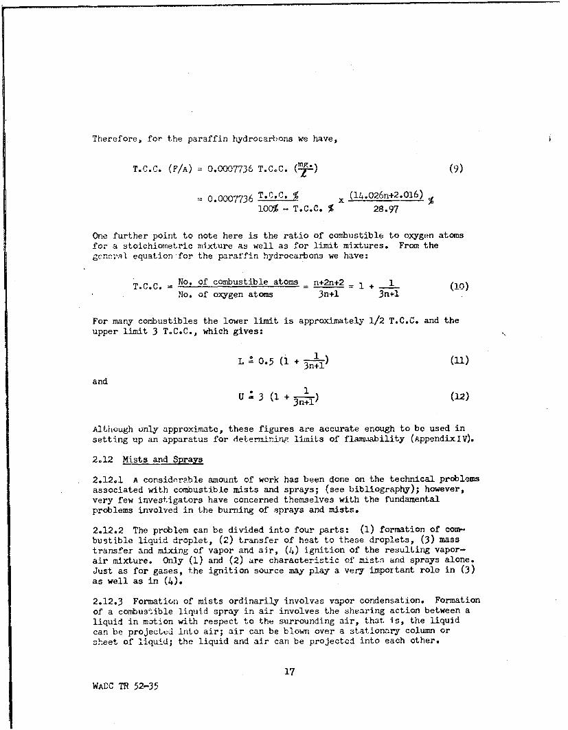
Therefore, for the paraffin hydrocarbons we have,
T.C.C. (F/A) = 0.000"773 T.CoC. Al) (9)
= 0.0007736 T.C.C. %x (14.026n+2.01 6 ) %100% - T.C.C. % 28.97
One further point to note here is the ratio of combustible to oxygen atomsfor a stoichiometric mixture as well as for limit mixtures. From the.cnc;...l equation -for the paraffin hydrocarbons we have:
T.C.C. = No. of combustible atoms - n+2n+2 =1 + 1 (10)No. of oxygen atoms 3n+l 3n+1
For many combustibles the lower limit is approximately 1/2 T.C.C. and theupper limit 3 T.C.C., which gives:
L 0.5 (1 + jq (U)
and• 1
U 3 (1 + (12)
Although only approximate, these figures are accurate enough to be used insetting up an apparatus for deter-Tining limits of flanivability (Appendix IV).
2.12 Mists and Sprays
2.12.1 A considerable amount of work has been done on the technical problemsassociated with combustible mists and sprays; (see bibliography); however,very few investigators have concerned themselves with the fundamentalproblems involved in the burning of sprays and mists.
2.12.2 The problem can be divided into four parts: (1) formation of com-bustible liquid droplet, (2) transfer of heat to these droplets, (3) masstransfer and mixing of vapor and air, (4) ignition of the resulting vapor-air mixture. Only (1) and (2) are characteristic of mists and sprays alone.Just as for gases, the ignition source may play a very important role in (3)as well as in (4).
2.12.3 Formation of mists ordinarily involves vapor condensation. Formationof a combustible liquid spray in air involves the shearing action between aliquid in motion with respect to the surrounding air, that is, the liquidcan be projected into air; air can be blown over a stationary column orsheet of liquid; the liquid and air can be projected into each other.
17
WADC TR 52-35

2J2.4 Measuremnrit of the particle size is a fundamental problem in thestudy of particles in a fluid. This is certainly true when consideringcombustible mists and sprays. However, before un-ortaking an actualmeasurement, one must decide what. type of size measurement is mostsignificant for the particular application involved. If the volume ofthe particle is of prime cmportance, this should be tdken into conslidera--,/'tion in the size measurement; likewise for the surface area, cross-sectional area, etc. For example, in the case of N spherical particles',one possibility would be:
x/
rave 1 (13
N j
or perhaps the effective radius would be more representative of a ratiosuch as the total volume to the total surface area so that, in general,
w N
rave K r__l _(14)
where x_ y 1. When studying the flammability characteristics of mistsW ZI
and sprays, the surface area is very important, accordingly equation (13)with x = 2 is of considerable -importance.
2.12.5 As usual, the problem of sampling must be considered very carefully,All impinger-type collection apparatus suffer on two counts in the case ofliquid droplet sampling. First, the collection efficiency of any impingeris a function of droplet size and velocity, and second the droplet size isa complex function of time and depends on a number of variables such asin-itial droplet size, temperature and pressure. This indicates that anoptical or electrical apparatus which does not disturb the individual dropletsappreciably would be preferable for measuring droplet sizes to the conven-tional coated slide and microscope arrangement.
18
WADC TR 52-35F
I I I II I I I I I ii , l , '

SECTION III
EXPERTMENTAL RESULTS
3ol The results obtaiaed from 19/ Februa.-y 1950 to 19 February 1952 aresummarized in this section under the headings: Limits of flammability;spark ignition energy measurements; ignition temperatures; and sprays andmists. The apparatus used for these investigations are de.cribed in theAppendix.
3.2 Limits of Flammability
3.2.1 CONCENTRATION LIMITS OF FLAMMABILITY (constant temperature): Aviationgasoline grades 100/130 and 115/145 and aviation jet fuel grade JP-3 havea high enough vapor pressure at 780F. to make saturated vapor-air mixturesof these combustibles nonflarunable because they contain an excess of corn-bustible vapor. However, the flammable areas of unsaturated vapor-air K Hmixtures of each of the above combustibles have been determined at 780F.(Figures 8, 9 and 10). The F-1 limit-of-flammability apparatus was usedfor these investigations (Figure 24, Appendix I).3.2.2 The limit-of-flammability curves in Figures 8a, 9a, and 10a are self-ilIexplanatory; the solid lines represent the limits of flammability for atmos-
pheric and reduced pressures of the vapors from a fresh sample of the fueltested. Consistent results were obtained provided less than 20 percent ofthe fresh liquid sample was used. This means that the percentages of heavyvapors in the vapor-air mixtures tested were small. However as the exact Pcomposition of the vapor-air mixtures tested is unknown, an average molecular Iweight was obtained for the gasoline samples from their distil; -ion curves(Figures la, lb), assuming them to be composed of straight cha- .:araffin I,hydrocarbons. This gave an ave2 age molecular weight of dpprox- .ely 100,corresponding to that of heptanu. The average molecular weight of aviationjet fuel grade JP-3 by the abov method was 128; however becaus: of thewide boiling range of this fuel (Fi-'Ure Id), this average molec tar weight wasnot used to obtain the F/A valu s in Figure lOb. Instead, the --'a ragemolecular weight used was the sume as for gasolines, the boiling range forthe first 20% of distillate for JP-3 fuel being almost the same as theboiling range for the gasolines (Figure 1). The F/A values used to plotFigures 8b, 9b, and 10b were caz3ulated from equation (9), assuming anaverage molecular weight of 100 in each case. Since only the first 20% ofthe fresh liquid sample that diE tilled over into the explosion chamber wasused in each case, an average wcight of 100 is probably high, suggesting 4that the F/A values in Figures 8b, 9b and 10b also are high. It is interest-ing to compare these derived data with the experimental data obtained withthe F-11 apparatus (Table 2) at 300-F. and one atmosphere pressure (Table 1).The data check as well as can be expected considering that the assumedmolecular weight used in obtaining the derived data was probably high, andalso that the data correspond to two different temperatures° However,Figures 8a, 9a and lOa, which represent the actual experimental data, should '
be used where possible in preference to Figures 8b, 9b and 10b plotted fromthe derived data. •
19
WADC TR 52-.35 [
I I I I I I I I I I I I I I ,

t LEGENDI Limit of flamnmability
SLimnit of igznitdabilitv with a Ford ignition coilb-Limit of ignitability wit h t he U.S. B. M. surge generator
r~i 1 -1 0
I~ A -7
24 t7/- ----A7 /t t_- L--~ F -jli -LL-
ZFla mma ble mixturesK *~' ~A ~ V/</-K 150
U) 16-- j - _f
I cZ
cc: ---§i7 -- -- -4f--t _ 2CL IU,
U31VI/ -Z- ZAl--------- 'i Z--
-a-z- -- <-5
T ilt 60/b -F 70
01 2 3 4 5 6 7 8
97 COMBUST iBLE- BY VOLUMEFigure 8a. - Concentration limits of flammability for aviation gasoline
grade 100/1-30 vapor-air mixtures at 78 +10 F.
WADC TR 52-35 20

I _LEGEND
Limit of ... "mabily- -- Limit of ignitability with a Ford ignition coil
b Limit of ignitabilfty with th.-. ' B M. surge generator
281Vi +/4 i/ ' ; - 0
244"
Flammable mixtures- -.. I
7 Io In~i20 / "07
TTIi,- I MK / -"- -L-
12 -----L -- 25I-
----- 7-,-'303- - 35,
SZ
FTN
_ _ 45_ 1a V 50V
-K_ _--H--60
_--F 70- W.L. --- t--4~ 80
0 0.05 0.10O 0.15 0.20 0.25 0.30
Figure 8b. - Concentration limits of flammability for aviation gasolinegrade 100/130 vapor-air mixtures at 78 -I 1" F. (curveIobtained from figure 8a taking average molecular weightof this fuel to be 100).
6 4I I I 2I I a:

LEGENDLimit of flammability I
Limit of ignitability with a Fced ignition coil
28 A- 7
Z_ _ 4 L/LLJ o. 12 - n
IFlammable mixtures/
o -- I------------------- -- - - -1- i o
4 -~ U.40F~amableixtues-------_- 45nK
z -- Z z-----------
~16 z. ii zL -0~--
C/, ~ - - - -- - - - - - -
-- -- - - - -- - - - -- - - - _Z
w-t - 0!X - -- -- - -- - - - - 0 11
0712 7 ML YLt3 7Az z w7
0~ 1Z 2 245 6
%o COMBUSTIBLE BY VOLUME !Figure 9a. - Concentration limits of flammability for aviation gasoline
grade 115/145 vapor-air mixtures at 78 + 2< F.
wADc TB 52-35 22
II~~_ I- II- -Z , I< I I II •I ... z

A
S/ LEGENDLimit of flammability
- ------- Limit of ignitability with a Ford ignition coil
24 --- - I I
-- X
L.L
o 20 Flammable mixtures 101z I /I V 1 I ,
z A A ;'0
_1 M
I~uLZ_ zv 770
C A• , z x-z
LLLL JLLL .. --_ "1-8
F ro t io la fo acc I DIi
ga 15 4 -vx-" _Z _ z -•6
0 0.05 A 3 30
F/A1Al V1 1-4Fiue b Cnet,....lmiso lmm blt4fraitongsln
gr1ad 11/ !4 vao-i mxue/a 8+2°. uv
0~ 0 .0- 5 0.001502. 0.503

_____'LEGEND
Limit of flammabilityLimrnit of 'Igni 'a bi Iity with a 15 kv. 30 ma.
/ luminous tube transformer
28 •L•4j 7 7 A jJI
z IIZ z -- Z-7- --
C -- Flammable mixtures-----
u-120 If. --- 110 '
71 7 z H1 z "I-r- r .I- - - /-
4J V I i- 2LiJ 715I-.1 -- -- - - - - - - - - - - - - - - -
-J z7C
12- -- - / z_____/JZ / 1
7 /1 7 Z~ 45M 7L-bE± - 60
4/ 700 1 2 3 4 5 6 .7 88
% COMBUSTIBLE BY VOLUMEFigure 10a. - Concentration limits of flammability-jet fuel grade JP-3
vapor-air mixtures at 79t 20 F.
WADC TR 5,,-35 .

LEGFENDLimnit of flammability
- Limit of i,ý7itabiiity with a 15 kv.30 ma.!uminous tube tran-sfIormer0
9Rw
24 - LI
0~
/I zI<-
C/)
800
0b 100).
WZ.L /TB 752-3535

Table i.... arison of limit of flamr-bility data obtainedidth two sets of apparatus at atmospheric pressure.
F-I Apparatus(7•F.) F-Il Apparatus (300-F.)•rived data) (Ixerimental F/A data)
Combustible Lower FTAUer F/A Lower FA U pper FiA
Aviation gasolinre -griade ]/."l0 0 01 0 071 0-041 0.27Aviation gasoline grade 115/145 -043 .255 .037 .26
Aviation jet fuel grade JP-3 .047 .287 .037 .30
3.2.3 One further point to bear in mind in conjunction with Figures 8, 9and 10 is that these figures are for data obtained at 770 - 81oF., andshould be used only for these temperatures. A limited number of tests wereP•r.•orme. d on aviation gasoline grade 100/130 vapor-air mixtures at OOF. toobtain graphs at OOF. similar to those in Figures 8, 9 and 10. However,the data obtained to date indicate that with fuel container and test chamberboth at O°Fo the limits of flammability correspond to values obtained forvarying butane, pentane, and hexane mixtures. The smaller the fraction offuel mixture vaporized into the test apparatus from the fuel container, thehigher are the lower and upper limits of flammability. The results obtainedto date are so erratic at this low temperature that no flammability curvesare available. The past history of the sample tested also plays a veryimportant part in the actual limit-of-flammability values obtained at lowtemperatures. Accordingly, in order to obtain useful limit-of-flammabilitydata for vapor-air mixtures that are not saturated with the combustiblevapors at; low temperatures, an initial series of tests should be conductedon butane-pentane-hexane control mixtures at low temperatures. If, asappears to be the case at present, the controlling hydrocarbons in thedetermination of the limits of flammability at temperatures below OF. arethe most volatile ones present in the mixture under the conditions oftemperature and pressure at which the test is conducted, then to improvea fuel mixture from the standpoint of safety at low temperatures andpressures, the volatile components should be removed. This means, of course,that as soon as a certain amount of butane, for instance, is exhausted fromthe mixture, then the pentane and hexane become the controlling hydrocarbons.Once a few control mixtures are investigated thoroughly, the problem of theflarmiability of complex hydrocarbon mixtures at low temperatures can beresolved more readily.
3.2.4 CONCENTRATION LIMITS OF FLAMM1ABILITY (constant pressure): The conocen-tration limits of flammability were determined for aviation gasoline grades100/130 and 115/345, and for aviation jet fuel grades JP-I and JP-3 at3000 F. with the F-11 apparatus (Appendix V). This apparatus is designedto determine the 4lim4t- of flarmmability of a combustible as a function oftempoerature at atmospheric pressure. The data &bt'alned fo r the four comf-bustibles mentioned are summarized in Table 2. The lower limit data in this
26
W-nDC TR 52-35

table may be compared with the data in Figure 7b, and with the calculateddAat obtaIned in paragraph 3.2.2 (Table 1). The lower imits of aviationgasoline grade 115/145 and of aviation jet fuel grades jP-i and JP-3 arein good agreement •with the curves of Figure 7b. The lower limit ofaviation gasoline grade 100/130 is rather high, however it correspondsrather closely to lower limit data for aromatic hydrocarbons (Ref. 39).As before, comparison with pure combustibles is rather difficult in theasene, of Ynore precise information un the composition of the vapors
given off.
Table 2.-The limits of flammfability in air of four aircraft.fuels at 3000F. and one atmosphere pressure.
Limtits of flanmabilityLower• Upper*
Combustible mg./l F/A mg./l F/A
Aviation gasoline grade 100/130 53 0.041 348 0.27Aviation gasoline grade 115/145 48 .037 337 026
Aviation jet fuel grade JP-I 48 .037 405 .31Aviation jet fuel grade JP-3 48 .037 387 .30
* The density of the air used for these data is that for conditions of
S.ToP. (OoC. and 760 mm. Hg)> The fuel density is that correspondingto 780F.
3.2.5 EQUILIBRIUM CONCENTRATION LIMITS OF FLaMMiBILITY (saturated combus-tible vapor-air mixtures): The cquilibrium concentration limits of flainma-bility have been determined for aviation gasoline grade 100/130 and 115/145and for aviation jet fuel grades JP-1 and JP-3. 'these limits are definedin paragrayn 2.6. The data obtained during the current investigation areincluded in Figures 11 to 14 with the equilibrium liquid-vapor-air tempera-ture plotted as abscissa against the absolute pressure as ordinate. Sinceeach of the above combustibles is a mixture of a large number of hydro-carbons, the flammable area obtained in each case depends on the historyof the sample tested. This is illustrated in Figures 13 and 14 by drawinga flammable area for the vapors given off by a fresh sample and again forthe vapors given by a sample from which a certain percentage of the liquid
has evaporated. These data should simulate the extreme conditions whichcan exist in the "air" space above the fuel in a fuel tank. When the tankis first filled, this "air" space becbmes saturated with a number of thevol-atile constituents present in the fuel. On an actual flight, the tank
"breathes" expelling more and more of the highly volatile constituents as
the altitude increases. When the altitude decreases, some more of the
liquid fuel vaporizes into the vapor-air space exiistirg in the tank. The
composition of the vapor above the fuel at any instant thus depends on the
past history of the fuel as well as on the temperature and pressure0 For
this reason, when determining the flammability characteristics of a fuel
mixture, it is important to know not only what percentage of the fuel
27
WADC TR 52-1ý

I5
/. N8_ ,_ I - ' ---- •• '
:E 20 2 n
r-<i K I I \NJ 15
Wl\ !J', N N7 !
24 'H i,,N .i-J I -l111 - \ B'• NUuIitiI. g\ I iL l
-__ _N _1 _ i\N ",,1
C,,11
W -- 20u A1
0o 30m< 8 " \ r, • I-358•
,, /N,•
-100 -80 -60 -4 -2 l40
TEMPERATURE OF COMBUSTIBLE VAPORAIR MIXTURE, F.Figure 11 -Equilibrium concentration limits of flammability
of the 0 to 5 107 fraction of aviation gasolinegrade 100/130 vapor-air ri-ixtures over thetemperature range -100 to 00 F. (the 0 to 5%76fraction of this fuel was d~stiiied under thetemperature and pressure conditions of eachtest).
wADO T0 52-305 2

1-LE G EIN DLimit of flammabilityLimit of ,,gnitibiity witha Ford ignition coil
28--- 4zFlammable mixtures 5
24 --- N -N- .\1\,jIWW 10 1-0
20 - C/5-- N N--- N- - 0
0~ ~ ~ ~ 2 a iII8
IN
Figur 12 •.,,•-
I \
-100~~~4 j8!60 -052
Figre 2 -4u,,,r,,um, concentration limits of flammabilityof the 0 to 10% fraction of aviation gasolinegrade 115/145 vapor-air mixtures over thetemperature range-l60 to 0° F. (the 0 to 10%o fraction of this fue was distilled under the
temperature and pressure conditions of each
WADC 52-35 29

-]LEGEND.....0 to 0 fraction
- -60 to 907o fraction
28 1\_ _r
Iý IT i
-- ,--•• -- -- 5 ' -'
24 -
Flammable mixtures- 10-•J20I\ I Q I\1 11
•16 -z
31,ii1 -255<o 350
,l2 8 i- - _ <
___ - -- 35•
cc61
S280
60 80 100 120 140 160 180 200TEMPERATURE OF COMBUSTIBLE VAPOR-A!R •MITURE, OF
Figre 3 -Equlibiumcon.centraton limits of flammability of the0 to 30% and 60 to 90% fractions of aviation jet fuelgrade JP-1 vapor-air mixtures over the temperature range
60 to 200° F. (the 0 to 30 and 60 to 90%7 fractions ofthis fuel were distilled under the temperature and 4pressure conditions of each test).
V/5I ; I I II 30

At 'rrlarniable miixtures__
\4I 4k W
0w i20 C :> . ŽiX ---
2: ~~~~0 tjo _----- ~d
0! <
W 16
W i 20 Li~-
_ _ J
4 S~ ---1
60
-80 -40 0 40 80 120 160 200TEMPERATUMRE' OF COMBUSTIBLE "VAPOR-AIR MIXTURE, OF.
Figure 14 Equilibrium concentration li111ts of flammability of the 0 to 5%and 80 to 90%6 fractions of aviation jet fuel grade JP-3 vapor-airmnixtu res over tek +mperature range -100 to + 2000 F. (the 0 to
5%~I Ind S0 toofi fue~l were distilled under the
temperature and pressure conditions of each test).
wADC TR 52-35 31
r

K,
raporizes into the tebt chamber but also the percentage of the originalfuel which vaporized prior to initiating the flammability tests. Fore ample, in Figure 14 the flammable area botween -1000 and 800F. wasobtained by using the aviation jet fuel graae JP-3 vapors obtained byvaporizing into the explosion chamber from 0 to 5% of a fresh sample ata temperature slightly above the explosion chamber temperature. The areabetween 1000 and 200'F. was obtained by using the JP-3 va'pors obtained byvaporizing into the explosion chamber the 80 to 90% portion of the originalsample placed in the saturator.
3.2.6 Figures 11-14 can be redrawn to give F/A as the abscissa with the 'aid of the fuel vapor-pressure data obtained from Figure 2. However, theReid vapor pressure data of Figure 2 apparently are not completely accurate,the F/A values obtained being inconsistent with all the other data reportedhere. Accordingly, these F/A plots have not been made. It should be notedthat Figures 11-14 are traces of the equilibrium limit curves (the curvesformed by the intersection of the flammable equilibrium concentrationsurface with the lower and upper concentration limit of flammability surfaces)on the temperature-pressure plane of Figure 6, whereas the proposed plotswould be traces of the equilibrium limits curves on the concentration-pressureplane. Furthermore, these proposed plots differ from Figures 8-10 in thatthese latter figures represent flammable areas at constant temperature sothat curves on the concentration-pressure plane would of course yield theidentical shape of flammable area. as the original; this is not true in the
case of the proposed plots.
3.3 Spark Ignition Energy Measurements.
3.3.1 Successful ignition of a flammable mixture by any ignition source
depends on the effective energy delivered to the system formed by thegaseous mixture and its surroundings. Whether or not a flammable mixtureignites depends on the useful energy from the ignition source delivered tothe flammable mixture being investigated, and also on the temporal mannerin which this energy is delivered to the mixture. In the course of experi-ments performed to date, various ignition sources have been used (Appendix X ).However, energy and power measurements were made on only one source, theUSBM surge generator, whose general efficiency as an ignition source at lowpressures is superior to that of any other ignition source used to date.In accordance with phases I and 2 of the program outlined for this project(paragraph 1.2.2), the limits of ignitibility of aviation gasoline grade100/130 vapor-air mixtures are being investigated at low pressures usingthe USBM surge generator as the ignition source. In accordance with theexperimental criterion to be used in determining the limits of flammabilityof a combustible-air mixture at a specified temperature and pressure (cf.paragraph 2.4.4),, most experiments conducted at room temperature and lowPressures ,eld limtof ignitibility which have been represented bybroken lines in Figures 8-10; this is not the case at reduced temperatures(Figures 11-14). Apparently at low temperatures the low pressure limit of
32
W,-OC TR 52-35

flammability rises enough to permit determination of the* low pressurelimit with several types of ignition source. As air -aft fuels are notordinarily used at. lw pressures and elevated temperatures, the problem ofignition may not be too difficult from a practical point of view. However,the data obtained to date irdicate that ignition at low pressures isachieved more readily with larger spark gaps than those used at atmos-pheric pressure.
3.3.2 To date, the lowest pressure at which an aviation gasoline graae100/130 vapor-air mixture has ignited and propagated flame is 0.63-inch Hgabsolute at 780F. This pressure corresponds to a standard altitude (butnot to the corresponding temperature) of 86,000 feet. However, for stoichio-metric mixtures, this was not a limit of flammability so that apparentlyonce the limit of flammability is obtained this altitude will be raised.
3.3.3 Typical current and voltage oscillograms of the energy surge deliveredto the spark gap in the explosion chamber are shown in Figure 15 and inter-preted in Figure 16. Figures 16a and 16b are traces of the oscillogramsgiven in Figures 15a and 15b. Figure 16c is a point by point multiplicationof Figures 16a and 16b and represents the instantaneous power delivered tothe spark gap as a fAnction of time; the area under the curve in Figure 16crepresents the energy delivered to the spark gap. The surge data obtained hi [Ito date are plotted in Figures 17-19.
3.3.4 Figure 17 is a plot of the limits of ignitibility of aviation gaso-line grade 115/145 vapor-air mixtures at low temperatures and pressures forthree ignition sources superimposed on the equilibrium concentration limitof flammability curves for the 0 to 10% fraction of this fuel (Figure 12).A 0.25-inch spark gap was used in all cases. Curve (a) gives the limits ofignitibility for a Ford ignition coil curve (b) for a 12O-qdllljoule, 550-
microsecond spark from the USBM surge generator, and curve (c) for an 85-millijoule, 275-microsecond spark from the same USJ3M surge generator(Appendix X ). This last spark appears to be the most efficient of thosetested for low temperatures. The problem of spark efficiency is beinginvestigated further with aviation gasoline grade 100/130 vapor-air mixtures(Figures 18 and 19).
3.3.5 Figure 18 is divided into three parts, each containing a family ofcurves for a stated aviation gasoline grade 100/130 vapor-air mixture. Eachcurve in the three families is a plot of the minimum ignition pressure(minimum pressure at which propagation of flame occurs throughout the mix-ture investigated) as a function of ignition spark duration. Two electrodesconfigurations were used for these curves. The first configuration (A)consisted of two 5/16-inch stainless steel rods mounted 1.75 inches apartin a glass base plate. From the ends of these rods #20 gage platinumelectrodes were mounted to gilve a 0.2.5--rih spark gap. The second configur-ation (B) consisted of two kovar-glass bushings mounted 1.75 inches apartL ina steel base plate. The platinum electrodes were mounted as above.
33
W-DC TR 52-35
MV1

7 ~ V fl I
777-~
44 +tt{ III41 1 1! !
IL I'-A -44 +
4tt l J:
II TId
b iFigure 15. - Oscillograrns of the (a) voltageacross and (b) current througha spark discharge gap in an haviation gasoline grade 115/145vapor-air mixture at-730 F. and27 inches Hg absolute. (See 1figure 16 for the analysis ofthese oScillograms).
V-00C TR 52-35 34&

C.I2 4 0 I I--!- -I -I I OscillogramNo. 551-3- -. -•- t Vertical ca!ibration= 180
o 160 - volts per inch8 --a-- Horizontal cal"ibrtion=115
of 80 ' - microseconds per inch0 < I i i I. Temperature=-73° F.Absolute pressure=27r , - ' ] inches Hg
c•324 ,II jiCharging voltage=15 kv
CL Oscillogramn No. 551-4
, 16 - Ver;Ical calibration= 10.1,, - \]I amperes per inch
-- -- Horizontal calibration=115- 8 - microseconds per inch
0 \ Temperature=-73° F.S Absolute pressure=27< - 1..,inches Hg
0 - - "---- Charging voltage=15 kv
S1600 ---
w 1200
0o -- Area -der curve=2.68 sq. in.Q. Factor=-40 millijoules per sq. in
S 800 - - Energy dissipated in spark,,,° _ ----- -- 117 millijoulesZ I\<I.- --
z 400
0 100 200 300SPARK DURATION. MICROSECONDS
Figure 16. - Analysis of oscillograms 551-3 and 551-4 givenin figures 15a and 15b.
WADC TR 52-35 35

a Limit of flammability---- Limit of ignitibility with ab Ford ignition coil
Limit of ignitibility with 120 millijoule,- 5550 microsecond spark
....... Limit of ignitibility with 85 miilijoule,27r-5 -,ic • ,, spark
28 -tt - ' 1j Il 11 1 1 IQ- I-
248 1 N I' N N
Flammable mixtures
2o -- -o--
o 16 - - -
LL 20 10
1- 25 5-- -- -- -
o I - - - - -30'
S-35z
C-) C
_ I - ~~4045)
~5O
TEMPEATIJEOF 700--1 -80 -60 -40 -0 80TEMPRATUE OFCOMBUSTIBLE VAPOR-AIR MIXTURE, °F.
Figure 17. - Limits of ignitibility of aviation gasoline grade1, 1 -,', vapor, air mixtures at low temperaturesand pressures for three ignition sourcessuperimposed on the equil1ibrium concentration
li ,.offa,,mmabi,,t curves ~o, th• Oto 10%fraction of the fuel.
W',Do T 52-35 36
II I I ~ ~I V)II I I I i i m m m. .

LEGENDGlass base plate, electrode configuralion A
a-12 to 50, b-50 to 100, c-100 to 150, d-150 to 200, e-200 to 500,
f-350 to 850, g-500 to 1,000, and h-1,000 to. 1,500 millijoules.
Steel base plate, electrode configuration B
i- 15 to 100, j- 100 to 900, k- 170to 300, and 1-340 to 490 millijoules.
-- Concentration 2.5 to.7% by volume 5
! i--- • l -70,000it _
1. _ - i) i Ii 7,oj
1.0-- - - _ ii l _' if 75,000
- - - [-I-- --{-F-, e 17K V71iw• I l td l I ll i 1I _ooo•
1.0 5.000X b
w _ 1_~ .... -- -. 7 5 ,0 0 0
--JConcentration= 2.99 to 3.01%o by volume-- 85,000 'x
.8 11 _ _t!! 909.000-
< o 2.0o ,oo ,.• *.o .0
1 -rea~ter tha'n _
Ii2.5 inches Hg.Concentration-5.1 to 5.5%o by volume 65-000
1.6-I II I II II I II m , 6•5,000
.8 ±+IFII.L.LLL~ziz -K -t7-80,000
0 400 800 1,200 1.600 2,000 2,400SPARK DURATION, MICROSECONDS
Figure 18. -Low pressure ignitability curves (minimum pressure at whichignition occurs plotted as a function of spark energy andtine duration) for the concentrations of aviation gasolinegrade 100/130 vapor in air noted on each set of graphs.
WADC Th 52-3$5 37

1.4 TI-
S-• 8 i 70,000
- Ih11i
-___ii 75,0001.0 --- I { T-
.4I LEGEND -
- 8 0, 0 0 0Occ
n-nna4L t 2 , n r = ,
[I - dconcentration=2.99,adecnetain-.5
__ __ __ __ !_ i8lll00IIIi
I' I I I ! -L._...1 .. 1. 111
O 200 400 600 800 1,000 9,200 0SPARK ENERGY, MILLIJOULES t!
Figure 19.--Low pressure ignitability curves (minimum pressure Lat which lgnltrod onfiguraotted as a function ofspark energy) for di7ferent coentntritions of aviationgasoline grade nt00/130 vapor-air mixtures and for twoelectrode conf-g-rationsg Duration of sparks is be-tween 500 and 2500 microseconds.
L III II ,g
0AQT 52005 3080 80 100,0
SPAR ENEGY, ILLUULE

//
3.3.6 Figure 19 gives five low pressure ignitibility curvcs for threeconcentration ranges and the t-wo electrode configurations (A) and (B)described above. The data used for these curves were obtained for a sparkduration between 500 and 2400 microseconds making the minimum ignitionpressures independent of spark duration (cf. Figure 18). The optimumspark igiiLion energy depends on the electrode confiouration as well ason the concentration of the combustible vapor-air mixture tested; in addi-tion probably the best electrode configuration is a function of thetemperature and pressure. However-, a few preliminary conclusions can bedrawn from Figures 18 and 19; namely, the optimum ignition energy forpressures below 2 inches Hg absolute is approximately 500 millijoules orgreater. Also, this energy should be delivered in approximately 500microseconds. (This applies to a 1/4-inch gap.)
3.4 Ignition Tempnratures
3.4.1 The minimum spontaneous ignition temperatures obtained for the fiveUSAF combustibles investigated are listed in Table 3. Data have beenobtained at one atmosphere and 1/2 atmosphere pressure for the combustiblesin contact with a pyrex surface, and at one atmosphere pressure with thecombustibles in contact with aluminum and magnesium surfaces (Table 3).An important point to note in connection with Table 3 is that when in con-tact with a magnesium surface (FS-l, Spec. QQ-M-44), no ignition occurs foraviation gasoline grade 100/130 up to 918 0 F. or for aviation gasolinegrade 115/145 up to 959 0 F. It is possible that these fuels may ignite abovethese temperatures, however tests were not continued to higher temperaturesfor fear of exceeding the spontaneous ignition temperature of the magnesium.
Table 3.-Minimum spontaneous ignition temperatures(OF.) in air.
At 1 atmosphere At 1/2 atmosphereCombustible in Pyrex in Al* in Mg* in Pyrex
aviation gasoline 824 824 918 1027grade 100/130
Aviation gasoline 880 842 959 1063grade 115/145
Aviation jet fuel 442 442 468 864grade JP-l
vivation jet fuel 460 486 484 840grade JP-3
Aviation hydraulic fluijd 437 424 448 838AN-0-366
*Aluminum S-1/2 hard, Spec. QQ-A-318
•- Magnesiud FS-i, Spec. QQ-M-44
39
WKDC TR 52-35
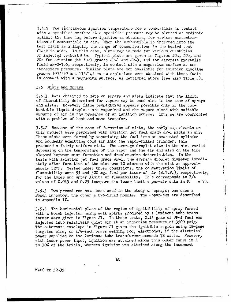
3.4.2 The shontaneous ignition temperature for a combustible in contact.ith a specified surface at a specified pressure may be plotted as ordinateagainst the time lag before ignition as abscissa -for varl.ous concentra-tions of combustible in air. ,,When the combustible is injected into thetest flask as a liquid, the range of concent~rations in the heated testflask is wide. In this case, plots may be made for various quantitiesof injected combustihle. rTypical plots are given in Figu'res 20a, 20b, and20c for a-'Jation jet fuel grades JP-i and JP-3. and for aircraft hydraulic
fluid AIN-0-366, respectively, in contact urith a magnesium surface at oneatmosphere pressure. Similar plots Pre not available for aviation gasolinegrades 100/130 and 115/145 as no explosions were obtained with these fuelsin contact with a magnesium surface, as mentioned above (see also Table 3).
3.5 Mists and Sprays
3.5.1 Data obtained to date on sprays and miLst indicate that the limitsof flammability determined for vapors may be used also in the case of spraysand mists. However, flame propagation appears possible only if the com-bustible liquid droplets are vaporized and the vapors mixed with suitableamounts of air in the presence of an ignition source. Thus we are confrontedwith a problem of heat and mass transfer.
3.5.2 BecAuse of the ease of formation of mists, the early experime.' s on
this project were performed with aviation jet fuel grade JP-l mists in air.These mists were formed by vaporizing the fuel into an evacuated cylinderand suddenly admitting cold air into the vapor-filled cylinder; this
produced a fairly uniform mist. The average droplet size in the mist varieddepending on the temperature of the vapor and the air and also on the timeelapsed between mist formation and droplet-size det3rminition. In thetests with aviation jet fuel grade J?-l, the average droplet diameter immedi-ately after formation of the mist was 10 microns wi.-h the mist at approxi-mately 32o°F. Tested under thcsc conditions, the co icentration limits offlammability were 55 and 300 mg. fuel per liter of iir (S.T.P.), respectively,for the lower and upper limits of flammability. Ths corresponds to F/Avalues of 0.043 and 0.23 (compare the lower limit v por-air data in FV e 7).
3.5.3 Two procedures have been used in the study o- sprays; one uses aBosch injector, the other a two-fluid nozzle. The -pparatus are describedin Appendix IX.
3.5-4 The horizontal plane of the region of ignitilility of spray formedwith a Bosch injector using weak sparks produced by a luminous tube trans-former aare given in Figure 21. In these tests, 0.15 gram of JP-l fuel wasinjected into relatively quiet air at an injection pressure of 3500 psig.The outermost envelope in Figure 21 gives the ignitible region using 18-gagetungsten wire, or i/8-inch brass welding rod, electrodes, if the electrical
power s pplied to the luminous tube transformer exceeds 78 watts. However,W-th lower power input, ignition was aLtained along this outer curve in 4to 10% of the trials,-whereas ignition was attained along the innermost
40
W-OC TR 52-15

550 __
, , n n l I I I I~ II I I I - I I I h
sso : ,• --L-I L,.E' EN--.D -t30 -Vt-I Sample used
0 0. 10 cc.51 .lo 15 I
510- 1 °.2040•__L-ih1 K •.25 -
450 ±!LLI-0 20 40 60 80 100 120
,, 1 J LEGEND570- SampIe used
0 0.10cc.:• F\ t //I °.15 I_u -55.20 1 I A.20
530
,,,510 1 1 Ha.
S490 b-, --
4701 1 1 10 20 40 60 80 100 120
530 LEGEND
510 .- .. Sample used -o 0.20cc.
490 a .25I .30
0 x .35
C450
0 40 80 120 160 200 240 NOTIME LAG BEFORE IGNITION
EXPLOSION, SECONDS
Figure 20. - Variations in spontaneous ignitiontemperatures with time lag before explosion
and quantity of combusUbie for, (a) aviation jetfuel grade JP-1, (b) aviation jet fuel grade JP-3and, (e.) aircraft hydraulic fluid AN-0-366 incontact with magnesium (FS-I, spec. QQ-M,44)in air at atrosplherc pressure.
wAC TR 52-35 41

(Y) -C)n -
-) tC-M
0 C))
Co Ii2: C3
CY)
z~0
Li) 00
'Z CUL
LLI 0I -r
4- 2
oUta)a
Li)Vw
0.
C)) 00- 01t 0
a)w
N I I
S3HONI '3iZZON 3
WAJ2C TR 52-3,5 2

envelope in 30 to 42 percent of the trials, etc. The equi-ignitionprouability curves (Figure 21) represent average curves obtained forthree spark gaps measuring I/8, 1/4 and 1/2-inch, respectively, thecorresponding primary powers being 30, 40 and 50 watts. These power in-
puts correspond to voltagcs that barely sustain an arc for the three gapsconsidered. When the electrodes were not permitted to cool between tests,ignition of the spray was more freqient than indicated by the envelopesin Figure 21; this was more noticeable for the tungsten than for the brasselectrodes.
3.5.5 The two-fluid nozzle spray apparatus is described in Appendix 1X.The only quantitative limit-of-flammability data obtained with thisapparatus to date consists of a lower limit of flammability fuel-air ratiofor aviation jet fuel grade JP-l of 0.0394. This value checks rather wellwith the data obtained for vapor-air mixtures (Figure 7). It was obtainedby considering the air-velocity data for the 60&- funnel (Figure 22), aswell as the air and jet fuel-feed rate to the two-fluid nozzle.
3.5.6 The air-velocity data in Figare 22 indicate that in general tohere.
is so much turbulence and entrained air involved in this type of air-velocity measurement that the problem of determining average fuel-airratios is complicated considerably by any surface close to the exit holeof a nozzle. ACcor-dingly, current work is performed by spray-in into theatmosphere with no restricting surfaces near the nozzle.
3.5.7 The spray-produced by the two-fluid nozzle consisted of a ratherheterogeneous mixture of various droplet diameters. Figure 23 shows atypical set of photomicrographs of the impressions made on a carbon coatedmicroscope slide by aviation jet fuel grade JP-I spray formed with a two-fluid nozzle. The droplet size variation is very marked here. Surfaceaveraged droplet diameters varied from 44 microns, 2.6 inches from thenozzle, to 8 microns, 16 inches from the nozzle.
43
WADC TR 52-35

" ~/
NEG.EG
040 .97.5 mm.
NNEG. _G 5 NEG EG. (3.84") -
SEG. -- 600 funnel !
5 5-..-777
(0 NEG. 0 NEG. 1 1 I
NEG 6"8
(05t r
>e.....s n2.8rd"o fe
.3 U.55 65
.38 .
Figure 22. -Total air velocities due to the primary air from atwo fluid nozzle plus the entrained secondary airfor three exit- chamnbers attached to the nozzle,(large circles Irepresent chamber outlets, numbersin small circles are velocities In hundreds of feetper minute).
WADC TR 52-35 144

/ W
/4
SC L
00 I'
- c3
C: o
E0
VADC TR52-354

SECTION IV
PROPOSED FUTURE INVTIG~pT, ONS•
4.1 Future investigations of the flammability characteristics of air-craft fuels should include at least four items.
4.2 The first item is the completion of the incomplete projccts enumer-ated under phases 1 and 2, paragraphs 1.2.2 and 1.2.3.
4o3 The second item involves the study of inerting at low pressures. For hexample, minirirmm o.gen requirements for flase propagation of various air-craft fuel-air-inerting gas mixtures will be studied at low and atmosphericpressures.
4.4 The third item on the present agenda is the study of the flammabilitycharacteristics of new fuels. Data from earlier investigations should beapplied to new fuel blends in an effort to decrease explosion hazards inthe proposed use of these fuels.
4.5 The fourth item may best be stated as follows: To investigate theflammability characteristics of various pure hydrocarbons found in typicalhydrocarbon blends and apply the resulting data to the study of the flamma-bility characteristics of control blends which initially may consist oftwo or three component mixtures of accurately known composition. Theseinv - igations would be especially important at low temperatures andprz •res as mentioned in paragraph 3.2.3.
46
WADC TR 52-35

SECTION V
CONCLUSIONS
5.1 The compositions of aviat4ion gasoline gradc:, 100/13"0 and 1115/145 amdof aviation jet fuel grade JP-3 are such as to permit flame propagationin vapor-air mixtures of the fuels over extremely -wide temperature andpressure ranges. Propagation of f3ame is possible at temperatures welbelow those encountered in the earth's atmosphere and for pressures corres-ponding to altitudes greater than those normally attained by present dayaircraft. Flame propagates through saturatcd vapor-air mixtures of theabove fuels at temperatures below -1O00F. and 2 inches Hg absolutepressure (62,000 feet). AS the temperature rises, flame propagatesthrough unsaturated vapor-air mixtures of the above fuels at still lowerpressures. For example, at 780F. flame propagates through a 2.99% aviationgasoline grade 100/130 vapor-air mixtures at an absolute pressure of 0.63-inch Hg (86,000 feet).
5.2 Flame could not propagate in aviation jet fuel grade JP-1 vapor-airmixtures existing below 680F. and 1.9 inches Hg (63,000 feet). The reasonfor this is that the fuel contains no highly volatile components so thatthe total vapor pressure of all the components is too low at temperatures
a much smaller explosion hazard from the standpoint of the vapor thatexists at temperatures normally encountered in handling and storage thando the three fuels discussed above.
5.3 An electric spark delivered over a relatively long period appears tobe more effective as an ignition source than one delivered in a series ofshort bursts, as in the case of a Ford ignition coil or a luminous tubetransformer. The surge generator built to achieve ignition at low pressuresis the most efficient ignition source used to date; other sources testedinclude, besides the surge generator, l-minous tubie transformers and Fordcoils, capacitor discharges, heated wires, fused wires, and guncotton, andare listed in the order of their effectiveness for the ignition of com-bustible vapor-air mixtures at low pressures.
5.-4 Of the combustibles investigated, the one most easily ignited spon-taneously at elevated temperatures and one atmosphere pressure was aircrafthydraulic fluid AN-0-366, with aviation jet fuel grades JP-l and JP-3following very closely in the order given. Aviation gasoline grades100/130 and 115/145 ignited spontaneously at much higher temperatures,listed in order of ease of ignition. The above statements hold whetherthe combustibles are in contact wi'th a pyrex, aluminum or magnesium surface,except that in the case of the magnesium surface the gasolines did notignite even wvhen the temperature was elevated to approximately the ignitiontemperature of the magnesium itself. The ease of ignition of the above
47
WADC TR 52-35
combustibles at one-half atmosphere pressure in contact with a pyrexsurface in air was in thc order, 3-iat.ion hydraulic fluid AN-(-366,aviation jet fuel grades JP-3 and JP-I, and aviation gasoline grades100/130 and 115/145. The corresponding minimum ignition temperaturesat one-half atmosphere were higher in all cascs than those at one atmos-phere pressures.
5.5 Orny a few of the problems associated with the ignition of mists andsprays have been investigated thus far. The concentration limits offlammability for very fine droplets appear to be approximately the sameas those found for vapor-air mixtures under the same conditions oftemperature and pressure. This indicates burning of vapor-air mixturessurrounding individual droplets so that the successful burning of anaggregate of combustible liquid droplets suspended in air presupposesvaporization of all or a portion of each droplet, followed by mixing ofthe vapor with the amount of air required to produce a flammable mixture.For this reason, the problems of heat transfer to liquid droplets andmixing of vapor and air by a flamc should be investigated. It is knownthat large amounts of power must be dissipated by the ignition source toachicyýC igni.tion of a sprany, but. energy requi1remens f prainiio•^• ... "•+-• • • •+.ene•=v•qu mpn s of spray ignitionhave not been investigated.
48

BIBLIOGRAPHY
BUrgovno T. H., and Ric.harF. 'h. . ".. - InflaTmwability of Oi0Vists. FucIl 28- ;'- n - 1-5, Ja.ma-,t 19.,9,
2o Castleman, R. A. ihe Mechanism of the Atomization (f Liquids.N.B.S. Jour. Res., 6, p. 369, 1931.
3. Coward, H. F. and Jones, G. W. Limits of Flammability of Gases andVapors. Bureau of Mines Bulletin 503 (Rev. of Bull. 279), 1952.
4. De Juhasz, K. J., Zahn, O. F., Jr., and Schweitzer, P. H. On theFor-ation and Dispersion of Oil Sprays. Bulletin 46, Penna. StateEngr. Exp. Station, 31, No. 29, 5 July 1937.
5. Dispersions in Gases. 17th Arimual Chem. Engr. Symposium. Reprintsfrom Ind. Eng. Chem., June 1951, and Anal. Chem., June 1951.
6. Godsave, G. A. E. Combustion of Droplets in a Fuel Spray. Nature,164, 22 October 1949.
7. Guest, P. G., Sikora, V. W., and Lewis, B. Static Electricity inHospital Operating Suites: Direct and Related Hazards and PertinentRemedies. Bureau of Mines Rept. of Investigations 4833, January 1952.
8. Jones, G. W. Inflammability of Mixed Gases. Bureau of Mines Tech.Paper 450, 38 pp., 1929.
9. Jones, G. W. and Spolan, I. Inflammability of Gasoline Vapor-AirMixtures at Low Pressures. Bureau of Mines Rept. of Investigations3966, 1946.
10. Kuehn. Atomization of Liquid Fuels, Parts I and II. Translated atNAv-CA, Tech. Memos. 329 and 330, 1925.
11. Lane, W. R. A Microburrette for Producing Small Liquid Drops ofKnown Size. Jour. of Sci. instr, ý- , pp. 98-101, 194".
12. Lee, D. W. adud Spencer, R. C. Photomicrographic Studies of FuelSprays. NACA Report No. 454.
13. Levvy, G. A, The Delivery of Small Drops of Liquid. Jour. Sci. Instr.,4 pp. 274-5, 1947.
14. Lewis, H. C., et al. Atomization of Liquids in High Velocity GasStreams. Ind. Eng. Chem., 0, 67, 1948.
15. Lewis, B. and von Elbet G. Combustion, Flares and EMlosions of Gases.Academic Press, Inc., New York, 1951.
49
WADC TR 52-35

16. Lloyj, P. The Fuel Problem in Gas Turbines. Inst. Mech. Engrs.Proc., 15, pp. 220-229, 1948. /
l7 ý MacLcinman, A. M. A Study of Kerosene Mist Explosions. Royal AircraftEst., Rept. No. Chem.. 448, Septembetr 1949, Tiscreet.
18. May,; K. R. An Lmproved Spinning Top Homogeneous Spraypparatus.Jour. App. Phys., 20, No. 10, po 932, October 1949.
19. Mellan, i. Industrial Solvents (Second Ed.), p. 61, Reinhold Publish-ing Corp., New York, 1950.
20. Merrington and Richardson. The Breakup of Liquid Jets. Proc. Phys.Soc., A59, 19417
21. Perry, J. H. Chemical Engineers Handbook (Third Ed.) McGraw-HillBook Co., New York, 1950.
22. Roof, J. G. A Temperature Control System. Electronics, p. 166,October 1943.
23. Ruedy, R. Absorption of Light and Heat Radiation by Small SphericalParticles. Canadian Jour. of Res., 19, Sec. A, pp. 117-125, No. 10,October 1941.
24. Rape, J. H. A Techni.ue for the Investigation of Spray Character-istics of Constant Flow Nozzles. The Third Symposium. on Combustion,Flaime and Explosion Phenomena, The Williams & Wilkins Co., Baltimore,Md., 1949.
25. Rupe, J. H. Critical Impact Velocities of Water Droplets as a Problemin Injector Spray Sampling. Progress Report No. 4-80, JPL Cal. Tech.,September 1950.
26. Schweitzer, P. H. Penetration of Oil Sprays. Bull. No. 46, PennState Engr. Exptý Station, 3i, No. 29, 5 July 1937.
27. Scott, G. S., Jones, G. W., and Scott, F. E. Determination of IgnitionTemperatures of Combustible Liquids and Gases. Modification of theDroE Method Apparatus. Anal. Chem., 2, March 1948, pp. 238-241.
28. Sinclair, Davis. LghtScattering by Sohorical Particles. J.O.S.A.,37, No. 6, p. 457, June 1947.
29. St. Clair, H. W., Spendlove, M. J. and Potter, E. V. Floculation ofAerosols by Intense High Frequency Sound. U. S. Bureau of Mines I•ept.of Investigations 4218, March 1948.
30. Stoker, R. L. A Method of Determining Lhe Size of Droplets Disuersedin a Gas. Jour. App. Phys., 17, No. 4, pp. 243-245, April 1946.
50
WRDC TR 52-35

31. Stull, D. R. Applicatiorn of P1•tintum Resistance Thermometry to SomeIrdustrial Physicouhwiýmcal Problems. Ind. Eng. Chem., pp. 234-21-2,15 Api-l 1946.
32. Stull, D. R. Vapor Pressure of Pure Substances, Organic Compounds.Ind. Eng. Chem., L-, p. 526, April 1947.
33. Suilivan, M. J., Wolfe, J. K. and Zisman, W. T. Flammability of theHigher Boiling Liquids arid Their Mists. lu-d. Eng. Chum., 97, To. 12,p. 1607, December 1947.
34. Swett, C. C., Jr. Spark Ignition of Flowing Gases, I - Energies toIgnite Propane-Air Mixtures in Pressure Range of 2 to 4 irichcsMercury Absolute. NACA RM E9E17, 1949.
35. Swett, C. C., Jr. Spark Ignition of Flowing Gases, II - Effect ofElectrode Parameters on Energy Required to Ignite a Propane-AirMixture. NACA PM E 51J12.
36. Taylor, L. T. The Inflammability Characteristics of Liquid Fuels.AFTR No. 5895, July 1949.
37. United States Government Printing Office, A. Eo C. Handbook onAerosols, Washington, D. C., 1950.
38. Zabetakis, M. G., Scott, G. S., and Jones, G. W. Limits of Flamma-bility of the Paraffin Hydrocarbons in Air. Ind. Eng. Chem., _3,No. 9, pp. 2120-24, September -51.
39. Zabetakis, M. G.,I Scott, G. S :nd Jones, G. W. The FlammabilityCharacteristics of the n-o• <romatic Series. U. S. Bureau ofMines Rept. of Investigations 3.24, October 1951.
51
WADC TR 52-35

APPENDIX I
The F-1 Concentration Limits-of-Flammibility Anppratus
Essentially the F-1 apparatus (Figure 24) is a partial pressurelimit-of-flammability apparatus (Ref. 9). The combustible to be studiedis placed in a 20 ml. glass container p attached to the apparatus at thelower branch of a T-bore stopcock o by a very short section of neoprenerubbcr tubing. To study mixtures of a combustible and an inert, theinert material container may be attached to the apparatus at the T-borestopcock o t . The neck of the glass container p butts against the stemof the T-bore stopcock. To prevent leaks, a hydrocarbon-insoluble greaseis used on the stopcock and a mercury seal q is placed around the glasscontainer and the neoprene rubber connection. At the beginning of a run,stopcocks o and of are connected between _ and a; plate b and mercuryseal c are put in place: mixer e is filled with mercury to outlet valveh by raising the leveling bulb g; the screw clamp on f is closed and theexplosion chamber is evacuated as completely as possible so as to bringthe manometer reading to within 0.1 mm. Hg of the barometer reading. Theair above the sample in p is removw,! through c, _, r and z. The sampleis introduced slowly into a by opening stopcock o until the manometerreading has decreased x mm. Stopcock o is then closed between p and a,and opened between q and a to allow air to enter a until the mercurycolumn in k falls to zero. The combustible and air in explosion chambera are mixed thoroughly by opening the pinch clamp on f and raising andlowering leveling bulb p at least 50 times. This gives a uniform com-bustible vapor-air mixture in which the percentage of combustible vaporby volume is ta 1 .en to be:
% combustible - (15)PB
where x partial pressure of combustible vapor, PB = barometric pressure.
If limits of flammability are to be determined below atmosphericpressure, combustible vapor-air mixture is removed through g, 2 and ofuntil manometer k indicates the desired pressure. The mercury seal c isthen removed, the room is darkened and a spark is passed between electrodesy. Visual observation is sufficient to determine whether or not themixture in the tube is explosive. This process is repeated until thelimiting mixtures have been found for a series of pressures at constanttemperature.
52
WADC TR 52-35

5L
It Il a *~ S wtc Transform ert
4-II -- rrnsork k
d Induction coil
hXg E
f q TO gas S
P holder
bC M
Motor Vacuum DryingPump tower
Figure 24. - Schematic diagram of the F-i limit of flarnmabi!ity apparatus.
WADC TE 52-35 53

APPENDIX II
The 1-08 Iition Temperature . Apparatus
The i-8 ignit.ion Tcmparature apparatus (Figure 25) (Ref. 39) is amodification of that developed by Scott, Jones and Scott (Ref. 27). Theessential unit of the apparatus is a standard Hoskins Type FD-104 electriccrucible furnace. This furnace consists of a heater f wound on an alundumcylinder _, whose inner diameter and height are 5 inches respectively. Thetop of the furnace is a transite ring h and the bottom is a transite disk a,both f'astened to a metal cylinder v. The insulation consists of sections r,r, and s. AS the operating temperatures at the top and bottom of the cruciblewell are below the temperature at the mid-section, a neck and base heaterwere added to the furnace. The torroidal neck heater e is wound on a tran-site ring k, using 50 feet of No. 26 B&S gage nichrome wire. A transite ringn keeps the 200-cc. erlenmeyer test flask a in place and supports theceramic insulators m. The temperatures at the neck, mid-section, and baseare measured by means of thermocouples b, c, cand d, respectively. Thesetemperatures are reuordedu on 3 channels of a 12-channel electronic tempera-ture recorder. The temperature variation between any two thermocouples iseasily kept at less than 1/20C. over the etntir working range of the appara-tus (the working range is limited by the softening point of the pyrex testflask). The temperatures of the three heaters are varied by means of threuautotransformers connected to the heaters by terminals t, t, u, u.
Operations with this apparatus may be divided into three steps: tempera-ture control, injection of sample, and observation. The first step involvesadjustment of the three autotransformers to bring the temperatures at thetop, center and bottom of the test flask', to within 1/20C. of the desired testtemperature. A measured amount of the sample is injected into the test flaskwith a 1-cc. hypodermic syringe calibrated in units of 0.01 cc. The insideof the test flask is then observed by means of a mirror placed at the appro-priate arnle above the flask. An electric timer is switched on at the instantthe sample is injected into the tesb flask and stopped at the first appearanceof flame in the flask. It is often necessary to darken the room in order tosee the flames which are rather light blue in color. If no flame appearswithin about 5 minutes, the volume of sample tested is considered nonflammableat the temperature of the test flask: The test is then repeated at a highertemperature and/or for a different concentration of combustible.
When tne 1-8 apparatus is used for low pressures it is housed in a low-pressure stecl chamber. This ch=her is equipped with an outlet porL attachedto a vacuum pump. a manometer, electrical connectors, a water-cooled coil,a liquid injector and an observation window. The procedure followed is thesame as for atmospheric pressure.
* Three test flasks were used for the inve.stiga-tions reported here; a 200 cc.erlenmeyer pyrex flask, a 500 cc. cylindrical aluminum (523-1/2 hard Spec.QQ-A-318) flask and a 500 cc. cyiindrica± magnesium (P'S-i Spec. QQM--44)flask. The cylindrical flasks were 4 inches high and 3 inches in diameter.
54
WijDC TR 52-35

AA
/c
xA>'
Fim~~ire 25. \ Dealddaigo \h - giintmeaueaprts
XA \- x- 52-3 x55

APPENDIX III
/Thc F-9 Tevc1peatur-e i Ls ts of Flammability Apparatus
This apparatus is used to determine the temperature limits of flamma.-bility for saturated combust-ible vapor-air mixtures at atmospheric and re-duced pressures. Since the vapor pressure of a combustible depends on thetemperature, the quantity of vapor in a saturated vapor-air mixture abovehe ccmbustible may be varied by varying the temperature of the combustible.f, in addition, the absolute pressure of the vapor-air mixture can be varied
while the temperature is kept constant, the concentration of fuel vapor inthe vapor-air mixture above the combustible may be v'ried. In this way,flammability tests can be conducted on saturated fuel vapor-air mixtures atvarious concentrations, thus making it possible to determine the limitingmixtures that lie between the explosive and nonexplosive regions. Sincethis is a vapor-pressure apparatus, very accurate temperature control isrequired. An accnirrte control of the absolute pressure in the explosionchamber -is necessary to define the limit mixture accurately.
The schematic diagram of this apparatus is given in Figure 26. A generalview of the F-9 explosion chanaber installed in an oven is given in Figure 27.The electronic temperature controller appears in Figure 32 with the F-liapparatus. Accordingly, this controller will be discussed in connection withthe F-ll apparatus in Appendix V. '
Approximately 20 cc. of the sample is injected into the system at c(Figure 26). The oven temperature is adjusted to the desired value and keptconstant during a series of tests. The absolute pressure in the explosionchamber is varied from test to test by means of pressure adjustment valve E.The vacuum pump is started and valves B and E are adjusted for the desired- rateof air flow through the saturator and the desired pressure in the explos.`ichamber. The rate of air flow through th,• saturator is kept low so thatvapor-air mixture in the explosion chadbe- is almost quiescent. The bul fthe vapor-air mixture moves up.Wa ,• .- " the explosion chamber at less than :nefoot per minute. A low air-flow rate als,, helps maintain a uniform tempe :.tureas the saturator does not cool noticeably due to vaporization of the samp.-11
Air enters the system at A, is dried and metered and passed into the pre-heater tube (5 mm. O.D. pyrex glass tubini, 125 cm. long). A sintered glasswell is attached to the end of the preheat'r. The air passes through thiswell into the sample in the saturator. T s saturator is half full of 3 mm.perforated glass beads that are covered bT the combustible liquid sample. Theexplosion chamber is flushed thoroughly sE;eral times with vapor-air mixture.The rubber hose segments between points- B and C, and points D and E arepinched off and the vacuum pump is stopped. If the pressure changes slightlyduring this last step, it is readjusted to the desired value. The room isthen darkened and a spark discharge passed through the vapor-air mixture aboutthree inches from the bottom of the explosion chamber. if a flame propagatesat least thirty inches (approximately 2/3 the length of the explosion chamber),the mixture is considered flammable. Flame propagation along 2/3 of the lengthof the tube is chosen as the governing criterion because the top portion ofthe eplosion chamber passes through the oven and exhausts into the air orinto a low-pressure system which is at room temperature and not at the tempera-ture of the oven.
56WRDC TR 52-35

0.0
CC0 CL
-~ CL
m C 00
in 0
0 a.
-E E
>E0
u E0
0 0Lcc Cn cr
040
C 2 -P 0
4v4-E
C Ui
-o 0
WAU TR5-355
:17 7.
ZIP.
r. AW
Fiur 2 los UP vie ofteF9 n -1 xlsochmbr intle nth vn
___D LR5-355
____ Ii

APPENDIX IV
The F-10 Ttnperatu.re IImit's G" Flar.bility Apparatus
The F-1O apparatus is similar L, the F-9 apparatus described inAppendix III. The F-lO explosion chamber is two inches in diameter by18 inches in length ana is housed in a cold chamber (Figures 28, 29 and 30).
In making a test with this apparatus, dry ice is first placed in the Isu-ze_-o _abInet _ (Figure 28) and the thermoregulator set for Lhe desiredtest temperature. When the desired steady-state temperature is reached inthe sub-zero cabinet, dry ice is placed in the Dewar cup surrounding watertrap &, which follows drying towers e and f, and a coolinig mixtur& in thecup surrounding saturator h. The compressor a is started and the initialpressure head adjusted by mcanis of c. The flow rate is set by the needlevalve preceding saturator h. Dried air almost saturated with combustiblevapor at a temperature slightly higher than the explosion chamber i, tempera- It
ture is passed through the explosion chamber, as in the case of the F-9apparatus (Appendix III). The air is metered by wet-test gas meter m afterall the vapor has been removed by liquid trap 1. Flask o and bubbler n areused when the vapor-air mixture is passed through the apparatus withoutbeing metered. The vapor-air mixture in the explosion chamber is testedas in the case of the F-9 apparatus, except that here the entirc explosion Ichamber is at the same reduced temperature and the criterion for flamma-Ibility of a mixture is flame propagation the entire length of the explosionchamber. The auxiliary apparatus k, p, Ex , s_, t, and u are used forpartial pressure determinations.
"Ii
APPENDIX V hThe F-11 Concentration L t-of-Flammaboiity Apparatus
Th F,-,l a-, . a fic.-type elevated-temperatureconstant-pressure concentration limit-of-flaini ability apparatus (Refs. 38and 39)- It consists of the following parts (Figures 27, 32, 33 and 34):
1. Constant-temperature bath
a. Oven and heatersb. Temperature recorderc. Temperature controller
2. F!piosion Chamher
3. Vaporizer and Mixer
59
WADC TR 52-35

I /1
!1H 0
Figure 28.- Schematic dia3ram of the- F., limitI .
V-AD0 TR 52-35 6o

t f+4
- - -'- -4 -I
Af 4)
Lti
EEd
-At.
i iiE-3I' •. I=__7
-IIt
WADC-TH 5235 6

Vt K
ww -
HdDC O'52356

II ,, '
Ig
' " I• iU|
ii i
00
w3

5714
kii
Ut- a-
(TC-19) used with the F-11i limit of flammabilityapparatus.
' A i I I I l 64

To contactor
4:1 I
AAf%.. a.c.
Oven
Partlow 11gv. a. C.control and I
-SI 2
T I A" 2 •
ILI d,. fIAiL W,.20k 2 1.oK"0- 0
'j 2050 V1(925) V2(92511 2050f
I ,, 1g S meg.
S4p3k I . g3k >
3ký
Figure 33. -Schematic diagram of the TC-i9 photoelectric temperature
controller used w-.ith the 17-94 and F-1 1 limit oil flammability
apparatus.
WC R• 52-35 65
a/ /
XUry
L .•. i i -1
1iF --i,. i
x- U • -d•- ----
s f
PiiI O-
Fiue ~.o ceatcdig-io h eletrca p rtin f h
lqin e l
Figure 34a. .An improved model of of the liquid feed service usedwi'th the F- 11 limit of flammability apparatus.
In
Figure 34b. -Schematic diagram of the electrical portion of theliquid feed device (improved model).
WADO Ti 52-35 6

4. Liquid-feed Device
* Drive urdtb. it'cdcrmic syringe and needleC. Adapters
5. Air-feed Assembly
a. Constant pr.-esure deviceb, Wet-test gas meter and calibratorc. Flowmeter
6. Ignition source
a. Electrodesb. Voltage source
1.,Constant-tenperature bath. An air bath is used to keep the explosionchamber and the vaporizer at a constant temperature. The air-bath housingconsists of a large two--door commercial oven (working chamber dimensions,37 x 25 x 50 inches). The oven is equipped with a 12-kw. lw-gracient heater.A 3-phase motor (440 volt, 3/A hp.) rotates a directly connected centrifugal
air over the heater and through th1 oven chamber. The oven temperature iscontrolled by a mercury expansion off-on thermostat, which keeps the oventemperature within 50 F. of the desired temperature, from 1000 to 5000F.Temperatures near the bottom, center, and top of the oven are recorded onthree channels of a 12-ch ,nel electronic temperature recorder; three No. 20B&S gage iron-constantin z-imocouples are mounted directly on the explosion
Additional temne eture control is provided by nine 1000-watt stripheaters installed in the ý--circulating duct of the oven; the temperature ofthese heaters is controll - by two variable autotransformers. The main(12 kw.) heater generally Is not used for temperatures below 2000 F.
A photoelectric temperature control (TC-19) is used to maintain theoven temperature constant to within ±1/40F. of any temperature from 1000 to5000F. This temperature control (Figure 33) is a modification of the oneused by Roof (Ref. 22). The sensing element consists of a No. 36 B&S gageplatinum wire wound into a l-am. helix, on a mica support (Ref. 31) placednear the top of the 12-•kw heater. Accordingly, the temperature coqtrolledis that near the upper end of one side of the 12-kw. heater. However, asthe recorded temperature is the oven temperature, by reading the recordperiodically, the control can be adjusted to give very satisfactory resultseven before a dynamic temperature equilibrium has been attained.
The platinum sensing element makes up-one leg of a commercial wheat-stone bridge. When the bridge is umbalanced by a change in the temperatureof the platinum wire, current flows through an I&N galvanometer G (Figure 33)
67
W•IDC TR 52-35

-.hosc s•ensitivity is 0.045 a per fitm. This curuent rotates the galvanometermirror so as to reflect the light from source S to photoelectric cell V1 orV2 , depending upon whether the temperature of the ptat-iiURI St:1f'3 g elementis greater or less than the desired temperature. If the oven is too hot,S 1 closes; this closes S3 , which in turn opens S4 and S5, thus breaking theflow of current, to the 22-kw. heater, If the oven is not hot enongh, thereverse sequence of relay operations occurs, iritiated by the opening of S 2 .34, which is nor-mally closed, makes it possible to use the apparatus at room
temperature, or at elevated temperature if necessary, even though TC-19 (thephotoelectric temperature controller) is inoperative. When TC-19 is in use,the Partlow mercury-expansion control is set at a temperature 3 0 F. above thedesired oven temperature to provide a safety switch. Thus, if TC-19 becomesinoperative during a heating cycle, the temperature rises until the micro-switch in the Partlow control shuts off the 12-kw. heater.
In using TC-19, the oven is first Drought to the desired tempera-ture with the Partlow control. Then TC-19 is turned on and the wheatstonebridge is adjusted to give a null indication on the galvanometer at thedesired temperature. The temperature record is examined periodically andthe wheatstone bridge adjusted if necessary.
2. Elosion chamber, The explosion chamber is a cylindrical pyrex-glasstube with an inner diameter of approximately 50 mm. and a length of 4 feet.The combustible gas-air mixture enters the cylinder through an opening at thebase. It moves up the cylinder at a rate of 3 to 15 inches per minute,depending on the rate of delivery of combustible and air to the system.
3. Vaporizer and mixer. The vaporizer and mixer consist of a continuous8-mm. pyrex tube approximately 12 feet long. They are designed to insurethorough mixing of the combustible liquid with the air delivered to the vapor-izer (Figures 27 and 32).
4. Liouid-fecd device. The liquid-feed device (Figure 34-) consists ofa drive unit housed in a brass body b_, a hypodermic syringe o with a 4-inchNo. 19 needle m,, which is inserted in the vaporizer 1, through a rubberstopper k, and a set of adapters r and g. The drive unit is mace up of a
1-RIPM fractional horsepower motor with built-in gear reducer n, 3 sets ofinterchangeable gears x and y, a machined feed screw 1/2-inch in diameterwith 20 threaas per inch c, and a driving head v, -,hich moves the plunger tof the hypodermic syringe o. This driving head is kept from rotating by aguide rod St. Standard 1-cc., 2-cc., 5-cc., and 10-cc. hypodermic syringesare used. The syringes are mounted in brass adapters _, which in turn aremounted on the base p of the liquid-feed device. The same adapter is usedfor the !-cc. and 5-cc. syringes so that a fiber sleeve r is inserted into _when the 1-cc. syringe is used. The length of thM adapt•cr can be adjustedso as to place the hypodermic syringe and needle in the proper vertical posi-tion. Once the proper position is found the adapter is locked by means of afiber set screw. A limited am:,ount of vertical positioning can be obtainedalso with height-adjustment screws on the four legs h of the liquid-feed
* The apparatus shown in Figulre 34 i mp an oved v.er.sion of the .cn use. for
the tests described in this report.
WADC TR 52-35 68

device; these are equipped with locking nuts, which keep them in placewhen the proper' syringe position has been found. In practice it is mucheasier to make all height, ndjustments With the brass adapters than withthe height-adjustment screws on the legs.
The vertical speed of the driving head depends primarily on thegears mounted on the drive shaft z and on the feed screw c. The distance be-tween the centers of the drive shait aind the feed -,crew is constant (32 mm.).Therefore, assuming that the same size teeth are used on the gears, the onlycriterion for the choice of gears is that the sum of the teeth on each setof two gears be a constant. The available gear sets have a total of 120teeth. since the shaft speed of the motor is 1 rpm and the machined feedscrew has 20 threads per inch, the rate of delivery of liquid by the liquid-feed device can be calculated for any particular hypodermic syringe and gearcombination; gears with 40, 4 5, 60. 75, and 80 teeth are available.
The electrical portion of the liquid-feed device (Figures 34a and 34b)consists of a 115-volt AC receptacle shell d, a reversing switch e, a lowcr-limit microswitch f, actuated by an adjustable rod a, a cable a, a phase-splitting condenser S, and an upper-limit microswitch w, actuated by theupper-limit bar u.
5. •_ir-feed assembly. The air-feed assembly consists of a constant-pressure device, a wet-test gas meter with its calibrator, and a flowmeter.
The main element of the constant pressure device consists of a bubb-ler a placed just before a high resistance consisting of a CaC1 2 drying tower,the wet-test gas meter, and the orifice of the flowmeter.
The wet-test gas meter is a nujol-filled, 3 liter per revolution,wet-test gas meter. The meter calibrator is made fro.-. a glass tube similarto the one used for the cxplosion chauber. Thie flowmeter is essentially awater-filled manometer calibrated to give approximate rates of air flow(Figure 32).
6. Ignition source. The ignition source is composed of a pair of No. 20B&S gage platinum-wire electrodes placed 3 inches from the base of the explo-sion chamber and spaced approximately 1/4-inch apart. The voltage source isa 15-kv., 30 ma. neon sign transformer. The primary of this transformer isconnected to an autotransformer.
In determining the concentration limits of flammability of a com-bustible in the F-1f apparatus, one must first calculate the amount of com-bustible theoretically needed for complete combustion (T.C.C.). This hasbeen done for the paraffin hydrocarbon series in paragrapn 2.11.2. A roughrule that may be used in setting up the F-1- apparatus for many hydrocarbonsis that the approximate values of the lower and upper limits of flammabilityare 0.5 x T.C.C. and 3 x T.C.C., respectively. Once these values and thespecific gravity of the hydrocarbon are known, the proper hypo-iermic syringe,liquid-feed device gears, and flovcreter setting are chosen; one determinationrequires approximately 30 minutes.
69
WjiDC TR 52-35

LI
The first exerimental step is . .u n of the ( rjol level
in the wet test gas meter d, (Figure 31) until the calibration of this meteris accurate to within ± 0-35%.
Tbh temperature of the exqplosion chamber o. J- a-jus ed to within!!4OF. of the desired value.
The air flow into the explosion chamber is adjusted to the desiredrate (4 to 20 liters of air per hour). This is sl].w enough to permit thetesting of th3 combustible-air mixture without fear of turbulence due tothe air flow.
The proper gears are put in place on the liquid feed assembly k_(this is determined by the choice of combustible and hypodermic syringe j)@
The hypodermic syringe J is filled to a predetermined level (a fiberblock is locked in place on the stem of the hypodermic syringe) and weighedon an analytical balance. The syringe is then mou.nted in &n aUdaunte whi.c,in turn, is mounted in the liquid feed assembly. The stem of the syringe islocked in place on the driving mechanism of the liquid feed device, and thefiber block is removed. liquid is'fed into the air stream at point i (pointsh and 1 are used when more than one liquid is to be fed into the air stream)of the vaporizer m.
The motor of the liquid feed device k, and the electric timer a, arestarted (both are connected to the same eledric, un-off switch), and thewet-test gas meter reading is recorded.
After enough vapor-air mixture has passed through the explosionchamber to flush it completely six times, the perforated cover p is removedfrom the explosion -3hamber and a spark is passed through the vapor-airmixture. The results are observed visually. If only a flame cap is producedby the spark, then the mixture is considered nonflammable. If a flametravels uniformly at least two-thirds or more of the length of the explosionchamber without having a broken flame front, then the mixture is considered
flammable. In general, a flame that travels two-thirds the length of theexplosion chambnr with a uniform flome front will travel the entire lengthof the explosion chamber. Flames which travel up the explosion chamberwith a brok. n flam.e front seldom travel over two thirds the length of thetub,; len they do, however, the test is repeated with the ener• of thespark source decreased so that it does not create a turbulent mixture in thetube. If the flame still appears erratic, the concentration of the vapor-air mixture is changed s)ightly and the test again repeated so that theflame either does or does not travel at least two thirds the length of theexplosion chamber.
The timer and the liquid-feed assembly are turned off, and the wet-test gas meter reading is recorded.
The pressure and temperature of the air in the wet-test gas meterare recorded.
70
WADC 711 52-35

The hypoderm.ic syringe and fiber block are again weighed on ananaly-tical balance
The composition of the vanc -nir nin±.-ucb.re tested is calculated asfollows:
//
Percent combustible by volume in a-r (thib is taken to mean the,'percent combutible by volume in the combustible-air mixture under condi-tions of normal temperature and pressure) at normal tempei:ature and pres-sure (NTP)=
6w(-M V) 100% , vi
w 6 + vP'T Vl+VaM PTI
ta w = weight of sample fed into system in the time interval
tfinal - tinitiaI = tf ti
yI = volume of liquid vapor (NTP) ccL-respcnding to .6w4% v = volume of air at temperature T' fed into system in the time
interv¢al tf - tiva = volume of air (NTP) corresponding to AvV = 22.4 litersT = 2730K.T? = temperature of air passing through the wet-test gas meterP = 760 mm. of mercury
in general, a series of four to eight tests is required to deter-mine the lower or upper limit of flammability of a combustible in air at anyparticular temperature and pressure. These limits are then plotted asabscissa against the temperature as ordinate.
The limits of flammability having been determined as the percentageby volume of combustible in air at NTP, they also may be expressed in termsof milligrams of combustible per liter of air (reduced to NTP), as follows:
L Mg.* L(% by vol. in air) MLliter(air) gOO - L(% by vol. in air)_7V
V = 22.4 liters; M = molecular weight of the combustible.
The fuel-air ratio, F/A, at the limits of flammability may bedetermined from the limits expressed in terms of mg./liter as follows:
F/A = L x 22 1= 0.000773 6 L( )1 28.97 x 10³ mgo
where L ramst be expressed in mge./iiter.
71
WADC TR 52-35

If L is expressed on a percentage basis, then
F/A L( x M10=L() 28.97
Or, using the original weight data we can write:
L = aw PTI mg.
tv P'T 1
and F/A = 0°0007736 •Aw PT'Sv P'T
The accuracy of this experiment may be determined by considering each ofthe above factors as follows:
Loss of sample due to evaporation around the plunger of the hypo-dermic syringe and the point of connection of the needle to the syringe.
Handling losses during weighing. These include, in addition toevaporation, loss of sample from the end of the 4-inch No. 19 hypo-dermic needle.
it is 4--p.. a÷± that the combustible sample be fed into the vapor-izer m, at a uniform rate, and that vaporization of the sample from thevaporizer into the air stream should not only be constant but s- *ld occurat a rate equal to the delivery cate of the sample into the var- zer. Theconstant rate of delivery of the sample to the vaporizer may be -fected byseveral factors:
Change in the density of the sample during an experiiw- -. (Anair conditioning system is ised to maintain the room temperatLure towithin less than 2 0 F. of thi desired temperature.)
Changes in the speed c' the driving motor in the liquid-feeddevice k.
Variation in pitch of .he driving screw in the liquid-feeddevice.
Large changes in the barometric pressure during an experiment.
Sv. This factor is obtained by mepnn of a wet.-+.Ptt gas meter,which is calibrated against a secondary standard; therefore, the accuracyof Av depends entirely on the accuracy of calibration of the wet-test gasmeter.
To ensure a honogeneous gas mixture, the rate of delivery of airtc the vaporizer also is important. This rate of delivery is maintained"a-ir'-- unform by means of a constant flow device; a flowmeter, and a valve(Figures 31 and 32).
72WADC TR 52-35

iIP1 and Tt. The accuracy of the first term depends on the
barometer that ii used and on the manometer f that is attached to the wet-test gas meter d. The accuracy of the second term depends on the thernome-ter e used in the wet-test gas meter.
Laboratory variations i i Pf and T! produce only negligible devi-
ations in the limits of flammability.
The variations in 46Aw/ 42 t and A, V/ A t are by far the most
critical. The variations of 6 wi 6 t depends, among other things, on theboiling point and surface tension of the combustible used and on the size.of the hypodermic syringe. The losses of several combustibles were deter-Smined by performing all the steps enumerated _Jn the above procedure without I'turning on the motor of the liquid-feed device. Losses of 2 to 5 mg. ofsample were found in some cases, representing a loss of 0.5 to 1% of thesample. As the error in the wet-test gas meter reading may be of the sameorder, the experiments generally are accurate to within + 2%, due to vari-ations in the air and liquid supply. The ovcr-all accuracy of the experi-ment should be within , allowing for temperature and pressure variations.
APPELNDIX VI ii
The F-12 Limit-of-Flammability Apparatus
The F-12 is basically the same as the F-1 apparatus (Appendix I). fIt differs from the F-1 apparatus in that its explosion chamber is housedin a 30 cubic foot cold chamber similar to the 8 cubic foot cham-ber used inconjunction with the F-10 apparatus (Appendix IV), and it uses a two-stageautomatic mixer similar to the one used with the F-2V apparatus (AppendixVIII). The 30 cubic foot cold chamber used with this-"apparatus has a work-ing chamber height of' 5 feet. The data obtained with this apparatus issimilar to the data obtained with the F-1 apparatus except that it is obtainedat low temperatures.
APPENDIX VII
The F-21 Temperature Lir-it-of-Flaeabill it~V Apparatus
The F-21 apparatus is similar to the F-9 apparatus described in AppendixIII except that its explosion chamber has an inside diameter -f 4 inches. Itis housed in the same oven as the F-9 apparatus and uses the same type of
saturator.
73
WADC TR 52-35

APPE.M.IX VIII
The F-24 Concentration Limit-of-Flaiapability Apparatus
The F-24 is basicallv similar to the F-i apparatus (Appg-endix I). !Tdiffers from the F-1 apparatus in several details (Figtres 35 and 36). Firstof all, the mixture to be tested is mixed in a 20-liter gas bottle j (Figure35) so that several low pressure tests ray be made on one mixture in the4-inch diameter explosion chamber a. Secondly, the mixing device is auto-matic consisting of mercury pumps g' and f_ which are operated by raisingand lowering mercury bottles E and f. Bottles & and f are raised and loweredby cros5s arm e which is coupled to a drive mechanism by means of a solidsteel irink. The drive mechanism consists of an electric drive motor, a gearreducer and an offset drive shaft (Figure 36). The remainder of the apparatusis similar to the F-1 apparatus as may be seen by comparing Figures 35 and24.
APPENDIX IX
.Snpray and M'is ,aI. ~•pparatus
Three types of apparatus have been used for these investigations. Thefirst type (for mists) consists of an apparatus similar to the F-9 (AppendixIII). The combustible to be misted is vaporized into the evacuated explo-sion chamber which is kept at a low temperature. Air at a low temperatureis then mixed with the vapor, thus forming the desired mist. The misttemperature can be controlled by varying the vapor and the air temperatures.
The second apparatus (F-26 spray apparatus, Figures 37 and 38) is acontinuous flow setup which uses a two-fluid nozzle to generate the spraysto be tested. The schematic diagram (Figure 37) of this apparatus listsall the components used in making spray ignition tests. It consists basic-ally of 5 components: a source of sujply of air, a source of supply of fuel,a two-fluid nozzle, a test chamber and an ignition so'urce. Rotameters areused to measure the flow rates of the air and fuel fed to the two-fluidnozzle which produces the spray. The spray is forced into the test chamberwhere it is tested by passing a number of sparks through it at various pointsi- the test chamber. An electronic photo timer, an autotransformer (variac),a luminous tube transformer and a set of spark electrodes make up the igni-tion system used with this apparatus. Auxiliary apparatus used in conjunctionwith the F-26 apparatus include droplet size measurement apparatus such ascollectors, microscopes and photoelectric microphotometer.
The third apparatus (F-27 spray apparatus, Figure 39) is a solid injec-tion type consisting of a hand pump and nozzle to produce the spray, and ahigh voltage spark apparatus to test the ignitibility of the spray. Thehand pump is an American Bosch nozzle test stand (APFH 1B-IOOB-S51), thenozzle holder an ARB35 Bosch holder, and the nozzle an ADN852 Bosch nozzle,set to open at a pressure of 3500 pounds per square inch.
74WRDC TR 52-35

Ma)
0 L0
I-.
cin
LO
tw
reuI
WADC R 52-*5 79

JI
rl
I J_
apaau In lac o a cua et
WADC TR A 52-35 76
'- 7
o *+ ++ !+
•+ • • I*~37Xr
Si
t+•++ -• -•++ -;I-++++-+++ >-++-i'• . + ., . F+j
S- +. +r+ :- ++ ++ •':++ +-"":=+ + ++ :.'++ ++ e 7 +=•I +
.. . . . . .. ,,+-' ' . . . .... .... ....... ........... ++ + . .......... -+, " r ,1•
________,.___....... ..... ___.____-___,_.__.......... . _______.... __ ___ ___.__..__. ..___ , ___!-
Fl~gure 3,6. General vIew of the F-27• ll•+it oC flammnability a+pp~rauiawith the aiurge g•enerator and it3 a+ssociated measurementapparatus in pleace for an actual test.
wADC T 52-35 76

011.
14 1
d %4
0 9x
1< I'
77f

wztl
-j ' n. ~ --
--- '-A ELIIt ~ ~Vk -
-.-:i -
utL'~ -$ ~ t%,~j~f2 *
'tat.Ii ¶ 7; £M
L.?J . %..
"Fiue79 h -s-6 cenrgr"4a 'Aol tyecryintinaprts
WAI JR 52-35 79

0 o3
li/ I. E
V 44
44
cn 00 0
•.co C42357
44
00
0Ie
KV00 0
000);
KIIAC TA 52-35 *79

The igrition apparatas conists of an electronic timer, an autotrans-former, a 15 kv., 3U ma. 1umniriuus tube transfon-sner and a set of spark elec-trodes. The secondary terminals of the lumiincus tulne transformer areconnected directly to the spark electrodes which are made of either 1/8-inchbrass weldirg rod or of i]-rgge tungsten wire. The procedure involves firstthe initiation of' a spark between the electrodes a-nd s..cond the p.roductUioof a single burst of spray ir. a fixed direction. This procedure is repeatedfor a nlbrer of spark electrode positions and spark power outputs in orderto determine the regions of ignitibility of the spray°
APPENDIX X
Ignition Sources
A number of ignition sources were employed during this investigation.These sources included Ford spark ignition coils, heated wires, guncotton,sparks produced by discharging a condenser, luminous tube transformers, anda surge generator which nroved to be the most efficient. However, foraltitudes to approximately 65,000 feet, a 15 kv., 30 ma. lum-nous tube trans-former is quite efficient. A 15 kv., 60 ma. luminous tube transformer worksnicely to approximately 70,000 feet. A surge generator has been used forignition at altitudes in excess of 80,000 feet.
The surge generator used at the U. S. Bureau of M1ines consists of 6basic components (Figure 40).
1. Power sunppl2. Surge generator3. Delay network4. Surge clipper5. Voltage and current measurement
circuits6. Associated power supplies and
calibrating circuits
1. Power supply: The power supply (Figure 41) is a conventional supplybuilt to charge the surge generator capacitors to any potential up to 20,000volts in approximately 3 seconds. The output voltage is adjustable over theentire range 0 to 20,000 volts by means of 6 variable autoLransformer placedon the primary side of the high voltage transformer. The charging vo±Lageis measured with an electrostatic voltmeter and kept constant during aseries of tests in order to make it more nearly possible to obtain sparksfrom the ,urge generator of constant enor,. -content. Tho ini-tia*! saur~ge Ofcharging current is limited by a suitable high voltage charging resistor.
80~
WADC TR 52-35

(-o 0.
4A >%>0 4)
10 0
LU IE
pip W -
CL U 06C U
L V4.
- 0 %4 cc-i ~~egs
a) a a)I 1(U .~ (0V 4
-~E uII~S,(UY
IVh W
'ba
4)D U 5234

CLI
to 0
Z 39
E E . 0
E
0.0-
4-'U Tlt 52-3 92

2. Surge generator: The surge generator (Figure 41) is composed pri-marily of a capacitor, series inductance and resjistance, and shunt i-sist-ance. The values of these circuit elemenLs are so chosen as to deliver aspark of lthe proper energy content, duration, and wave shape that isdesired for a given application. An over-damped, or non-oscillatory waveij generally used. The capacitor (or capacitors) is charged to a steadyvoltage by the power supply and then discharged by means of a small trigger-irg pulse applied to the triggering gap. The surge voltage appears acrossthe shunt resistance (which i also the voltage divider) and.. the spark gap(in the explosion chanber) which then sparks over. The capacitor is tbeenergy storage element, but over 99% of its energy is dissipated inl theresJstors. A good grade of oil-filled mica capacitor is used which iscapable of withstanding 20,000 volts and having low internal resistance andinductance. A series inductance is used to reduce the initial rate of riseof voltage across the gap and also the rate. of rise of discharge currentthrough the gap. These features help to insure more consistent sparking ofthe gap and more reliable voltage measurements by the non-inductiveresistors, whiich might give erroneous results with a steep-front wave.The series resistance (part of which is the current shunt) is. adjustablebo as to vary the maximum surge current and duration of the spark. Thisresistance may be varied along with the capacitor in various ways to changespark energy and duration more or less independently. All the resistancesused are of the wire-wound, non-inductive type.,
3. Delay circuit: In order to be able to display on the oscilloscopescreens the traces of spark voltage and current, it is necessary to delay insome way the signal representing these values by the time required to initi-ate the sweep I- se and permit an inch or so of travel on the linear partof the sweep. s is accomplished by means of a time delay circuit(Figure 42), wý produces two pulses with an adjustable time intervalbetween them. first pulse, a low voltage one, triggers the sweep whenthe "delay trip- button is depressed, and the second pulse, a hi*gh voltageone, t ggl generato+r and tie • ezt gap breaks do,-wn almiosti nstantaneously The triggering gap of the surge generator is "sensitized"by means of radi,,active material to make it operate consistently.
4o Surge clipping circuit: The voltage required to spark-over the bombgap and to deliver the required current may be 100 to 200 times t'he minimumarc voltage existing across the gap after breakdown. it is desirable toobtain on the screen of the cathode ray tube a reasonable deflection repre-senting this arc voltage, which is of the :rder of 50 volts. At the sametime, the tube must be protected against the pre-breakdown voltage, whichmay be several times the voltage rating of the deflecting plates, which is1000 volts in the_, case of +ieh 5CPII-A tube in the Dumnont 304-H oscilloscope.This protection is accomplished by means of the clipping circuit (Figure 43).The clipping tube is a diode biased so as to clip off all of that portionof the voltage wave above 1000 volts, but to leave undisturbed that portionwhich is less than 1000 volts, which -Is a range sufficient enough to recordall oscillograras encou..ter thus far. The cathode-ray tube is so designedthat voltages may be apnlied up to six times that represented by the on-screentrace, without distorting the on-screen deflection.
83
WADC TR 52-35

Lna
'4
fnl
0.. .. ,-,
C44
a~ 1-- 04
IIn
('a + '
CIA !d
04.
WADC Ts 52-3

L • cl;.,er
S150 k. k
7I l8
To"!ve" C. Re T. •7vertical plate +930 v. x x liIx xII
o"S. av puate in 8
1Pfd 3 i,50 k. il~d
20 w. 6.W4ITo ground " • Ir- ,4i in
Sii
2 2k.x X
,,-+±700 v. \ U6.av.
SFuse
A. C.
Figur~e 43.--Circuit diagram of the surge clipper.
ws,,,C ,. 52-345 85
5. Voltage and current measurement, circuits: The surge voltage ac--ossthe test gap was measured with a voltage divider composed of non-inductive.resistors totaliw about 8C00 olms: thi .value was chosen so as to be sub-stantially larger than any series -eoistance which might be placed in thesurge generator. This divider was divided into two parts, one being atthe gap end of the coaxial cable arid the other part being at the oscillo-graph end. The oscillograph plates were connected across this secondsection so that the oscillograph observed about half the voltage appearingat the test gap. With the tranLsients observed to date it has not beennecessary to terminate the voltage cable with its characteristic impedance,thereby making it possible to couple directly to the plates of the oscillo-graph without the use of amplifiers.
The current through the test gap is likewise measired with a suit-able non-inductive resistor and the signal transmitted to the oscillographthrough a coaxial 3able. This cable was terminated by its characteristicimpedance of 75 ohms.
The non-induct-ive resistors used were of the powe ' ware-wound type,having zero voltage and temperature coefficients of resistance under theexperimental conditions. Both mr~nufaeturerts speeifications and a check wi•th
a radioý-frequency bridge confirmed the excellent frequency response of theseresistors, the impedance being equal to the D.C. resistaice up to one mega-cycle, with less than one np , devia+ion• Oe megacycle is somewhat
higher than the highest harmonic which might be derived from analysis ofthe impulses reported here, so these resistors are considered satisfactoryfor the measurements undertaken in conjunction with the ignition energy workdescribed in Section 3ý3.
The basic oscillograph used to record the oscillogramis reported herewas a Dumont 304-H. An auxiliary, or "slave" oscillograph (Figure 44), wasbuilt having a common sweep signal with the 304-H, or "master" unit. Thismade it possible-to record simultaneously oseillograms of' voltage andcurrent as a function of time. "Iwo Dumont Type 296 cameras were used torecord the oscillograpns, all on 35 Tm. Super XX film. It is considered thatmore accurate and more easily interpreted results can be obtained by plottingcurrent and voltage against time separately than by plotting current againstvoltage. The "tslavet" unit has independent position, focus, and Lintensitycontrols. As mentioned previously, the signals were coupled directly tothe vertical deflection plates, so there is no problem with gain and responseof bhe vertical amplifier.
Frequently, during a series of tests, it is necessary to calibratethe X-axis, or time base, of the oscillogramso For this calibration a sinewave is double exposed on the oscillograms by means of an accurate signalgenerator connected through the Vertical amplifier. The calibration, con-vuniently expressed in mdcroseconds per inch, changes very little during thecourse of a day for a given setting of sweep and horizontal gain controls.
86
WADC TR 52--35

- - To point "B"2M 2M C.R.T. 1l00 V.
r ~~To D4 vert. amp. 5C Pi1-A T TO D?" To Dlho'- amlp. hor. amnp.
S(back panel)
0. P. D. T. 0.1ju ,1,00 fvdknife switch 8 1,000 V.4T100V
11 1M0.|
0.~d 0. 1u fd - o- Ho oitoTo point "A" 1'1,000 V. 1 ( 0"00- -. 9 o1toL n
390V. Vert. position 5 L R8.B
6--.- .1Jd _/ -
To pointA"=- , 0 v. !,C270 R7 . -R8-- B 6 °.3 - -- H..6osiio
V9+390 v. 0.ert.f 220Kio C28 15 . • R1 r
5M[lO 5MM21ý20 ppd, ' Dua
"To -140 6 .ofC2 BF1 B63v.06
D•lntensty R79 B pot__f
T°€casis -• To
2120K
-2 -9 .110
Figre442C0'ui dig of t1 C~~able' cahonnection t~1o mster utoope~t~wit Dui~ttyp (typ e304-Hoscilcope.
"t 5
'Too pin of R78
To- -2 140 v.
To ~ ~ t chassi 11ou yp 0-1 osV. 0_C•
w•~~A C.52]58

Calibration of the Y-axis is acmc.4lished by taking a series ofoscilcgrams of 6-0.-cycle voltages applied directly to tht vortical plates,annd measured with an accurate 6 0-cycle voltmietero This calibration canbe made to Pbout ± 1% and does not change over a long period of tiine. A°C.must be used instead of D.C. because of the capacitor coupling that isnecessa-y in the osrillograph dircuits to block the D.C. positioning volt-ages. The background illumination on the screen can be adjusted so thatthe ruled grid can be superimposed on the oscillograms for purposes ofmeasurement.
7. Voltage and current s1res: A typical voltage and current surgeproduced by a simplified surge generator is given in Figure 45. The surge Iparamieters used for the actual and theoretical waves are giver, tn the insert.
88f!: I,ii!'I
II.II
W•DC ,~52-3
No 00
E -M-~~~ m~~-__ -4--- __
a-cc- ~ __ _
V) us
we -
_7 0.E
0
0
t! 76 W4c,/ %DV1O 1A4V
W0-C T3 52358

A
INDEX
PageApparatus
F-i, concentration limit of flammability--------- 52F-9, temperature limits of flammaoility .. 56F-10, temperature limits of flammability --------------- 59
F-11, concentratio 1 '.1±t- .ý UU 5 9L..t
F-12, limit of flammability ------------ --------------- 73F-21. temperature limit of flammability ------------ --- 73F-24, concentration lindt of flamn.ability-- 74F-26, Spray apparatus ------------------ --------------- 74F--27, spray apparatus ---------------- ---------------- 741-8, ignition temperature ------------------- ----- ---- 54Ignition sources 80
Aviation gasoline, grade 100/130ASBT distillation curve --.-.-.-------------.------ -- ------ 2in air, concentration limits of flammability at OOF.,
discussion - --- ------------------ 26in air, concentration limits of flaiwmbility at 780F. - - - 20, 21in air, equilibrium concentration limits of flammability-- 28in air, limits of flammability, table------------------ ---- 6, 27in air, low pressure ignitibility curves --------------- 37, 38in air, minimum SIT, table ------------------- --------- 39Reid vapor pressure curve------------------ ------- 3
Aviation gasoline, grade 115/145ASTK distillation curve-------------- ---------- 2in air, concentration limits of flammaoility at 78OF. - 22, 23in air, eqailibrium concentration limits of flammaoility-- 29in air, limits of flammability, table ----- ------------ 26, 27in air, limits of ignitibility --------------- --------- 36in air, minimum SIT, table ------------------- --------- 39Reid vapor pressure curve- - ---------------- 3
-4ivation hydraulic fluid AN-0-366in air, minimum SIT, table - - ------------ ---- --- - 39in air, variation in SIT with time lag -l------ ------- 41
Aviation jet fuel, grade JP-1-STM distillation curve-- -------------- ---- 2
in air, droplet sizes- ----- -------- - ---- -- - 43in air, equilibrium concentration limits of flammability- - 30in air, for.mation of mists 40in air, formation of sprays ------------------ --------- 40in air, limits of flammaoility, table - ----------------- 27in air, lines of equilibrium igrniLion probability for
sprays in a horizontal plane - - - ---------------- - -- 45in air, minimum SIT, table -.-.-.---- -------- ----------- -39in air, variation in SIT with time lag -- ----------- --- 41Reid,vapor-pressure curve .........-... ..---.-- -----------
90
W•DC TR 52-35

INDEXPage
aviation jet fuel, grade JP-3ASTYI distillation curve------------------ ------------- 2in air, concentration liidts of flammabijity at 79 0 F. - - - 21, 215in air, equilibriim concentration lim-its of flanmaoility 31in air, limts of flammability, table ---------------- --- 26, 27in air, minimum SIT, table ----------------- ------------- 39in air, variation in SIT with tiNe lag ------------- ----- 41Reid vapor-prascure curve 3
Bibliograpy - - - --- - - -- --------------- oBurning process asscciated with combustible droplets ------------- 13Batane in air, ignitibility curve----------------- ------- 8
Conclusiorns -------------- - ----------- 47
n-decane in air, lower limit of flarwmnability ----------- 15
Energy measurements, spark ignition 32
Flanm;ability characteristics of combuStible gases and vapors,definition -l- - - ---------- - -------------------------- ----- 11
Flaamable gaseous mixtures, combustion of -.-------------- ----- 14Flammaole volume, general foiT ------------------------------- 13Flash point --------------- ----------------------------- ----- 9, 10Fuels------------------------------------ 1Future investigations --------------------------------------- 46
Gaseous mixture, definitionfD n..mable------------------- ------------- 5r lammable--------- ---------------- 5
n-heptane in air, lower limit of flamnability ----------- ----- 15
n-hexane in air, lower limi.t of flammability ------------ ----- 15
Ignition temperatures ----------------- ----------------------- -39
Le Chatelier t s law -------- --------------------------- ------- 12Limit mixture, definition------- -------------- 5Limit. of flammability, concentration, definition---------- 6Limits of fla-anbility, effect of temperature and pressure on 6Limits of flan1wability, experimenta± criterion for the
.determination of------------------------------- 6Li-mTits of flammubility, experimental results ------------------ 19Limits of flanmmability, general form of constant pressure
curves- -- ----------- - -------- ------------- --- -- -------------Limts of fia•-natili+ in ir, app•o•it ... lues of------ -------- 17Limit of flammability, low pressure, definition -i- - -------- - -- 11
91
W&DC TR 52-35

INDftPage
Limit of flammability, lower, definition----- ---------- 6Limits of flamzability, temperature or equilibrium concentra-
tion, definition - - ------------ - ---------- - - - - - --- 7LiTj -- ts of flamnmability, temperature, general form of
saturated vapor-air curves ------- ------ --- - ------------ 1C0L.nit of flainmability, upper, definition- ------------- 6Limit of it.tiblity, definition------------- --------- 7Liquid mixtures ------------------------ 12
Mists ------------------- ----------------------- ------------- 17, 40
n-nonane in air, lower limit of flammability ------------------ 15
iso-octane in air, lower limit of flammability-- - ------------- 15n-octane in air, lower limit of flan-mability - ----------------- 15osci..ogra, voltage and current, analysis - 35oscillograms, voltage across and current thr-ough a spark
discharge gap--------------- ------------- ------- 34
Phase 1 - -- -- -- -- -- -- -- -- -- -- - - ---
Phase 2 --- -------- ----------- ---------------- 1Program --------------------------- - 1Pu~re liauids- ----------------- - -------------------------- -- - - 11Purpose----------------- ------------------- --------- 1
Raoult's law ---------- ------------------------- ------------- 12
Size mea.3urement, heterogeneous mixture of sizes - ------ 18Size measurement, sampling methods - ------------------- ------- 183pontaneous ignition temperature: definition -.-.-.-.---------- - - 1!Spontaneous ignition temperature, minimunm, definition -------- 11
Sprays 17, 40photomicrographs .................. - - 45
Stoichiometric inxtures ----- ------- ------- ------- --------- 14
Time lag before ignition, definition nnnnnnnnnnnnnnnnnnnnnnn n 11T.C.C., definitionnnnnnnnnnnnnnnnnnnnnnnnn - --nnnnnnnnnnnnn 16T.C.C, for paraffin hydrocarbons in air, expresses as a
fuel-air weight ratio - - - -------- ------- ------- ------- 16T.C.C. for paraffin hydrocarbons in air, expressed as a
ratio of combustible to oxygen atoms -- ------- ------ 17T.C.C. for paraffin hydrocarbons in air, expressed in mg.
combustible per liter of air ...--------.------ 17T.C.C. for paraffin hydrocarbons in air, expressed in percent
by volume -.-.-.-- ------- -- - -.- - - - - - - - - - - 16Týo-fluid nozzle, air velocities -.------------ ------- ------- - 45
sprays produced by -.-.-.-.-- - - - -- -nnn -n4-3, 45
92
W1KDC TR 52-35

UNCLASSIFIED
UNCLASSIFIED