research on shear test methods of bonded steel bolts · pdf file · 2017-08-25test...
TRANSCRIPT
Research on Shear Test methods of bonded steel bolts
*Quan Xueyou1), Li Xiongsong2) and Luo Chujie2)
1), 2)School of Civil Engineering, Chongqing University 1), 2)Key Laboratory of New Technology for Construction of Cities in Mountain Area
(Chongqing University), Ministry of Education, Chongqing 400045, China 1)
ABSTRACT
Anchor bolts, while traditional single anchor shear test (SST) method adopted, would not only be subjected to shear force, but to tension force and bending moment as well. In order to disclose the real mechanical characteristics of shear anchors and build their practical shear vs slip relations, an alternative shear test method, named true shear test (TST) herein, is proposed. Test results showed that dispersion of experimental shear vs slip curves when TST method adopted are much less than when SST method is used, while secant shear rigidity at design load level is much higher than when SST method is adopted.
1 .INTRODUCTION
Post-installed adhesive anchors are often used to connect other structural steel components or equipment to concrete structures. Those connections are related to safety and therefore the design check of the connection performance of the anchor bolts are required. Anchor bolts connections in actual engineering projects usually work as anchors group and can be subjected to bending moment, shear force or their combinations. The connection steel plate is usually assumed to be a rigid plate when checking the bearing capacity of the adhesive anchor connection. The anchors in each connection plate may suffer tension, shear or tension-shear due to different loading
conditions and construction details. According to ACI318-4 (2014)、NZS 3101(2006)
and GB 50367 (2013), when the strength of an anchors group is governed by breakage of concrete base, the bearing capacity of the anchors group can be determined by the elastic analysis method, with forces distributed in each anchor bolt determined according to their positions and the ultimate capacities of the anchors group controlled by the most critical anchor bolt. When failure mode of anchors group is dominated by
1) Professor
2) Graduate Student
ductile failure of all anchor blots, full internal force redistribution can be assumed and the ultimate load bearing capacities of the connection is totally determined by strength of the anchors. In those cases, there is no need to consider the quantitative relationship between the force of the anchor and the deformation of the anchor.
Over the past several decades, bonded steel plates have been widely used in the strengthening of concrete structures. Due to the risk of debonding failure and the difficulty for the adhesive resin to meet the fireproof requirements, the application of bonded steel reinforcement method is limited on many occasions so that other solutions are being explored in the engineering circle. Many researchers turned to bolted steel plates for strengthening of concrete beams. T.M. Roberts (1989) bolted thin steel plates to the tension face concrete beams to strengthen the flexural strength and gained great increases in flexural rigidity and moment capacity. Oehlers (1997) and Nguyen (2001) conducted a study on the flexural capacity of RC beams strengthened with anchored steel plates on beam-sides; Barnes (2001) studied the shear capacity of reinforced concrete beams with anchored steel plates. Su (2010) studied strength enhancement and ductility of plated concrete beams for different side anchor and steel plate layout. L.Z. Li (2017) studied effects of parameters such as blot spacing, plate breadth and thickness on the strength and ductility of the strengthened members, and noted relative slip between steel plate and concrete substrate.
Bolted steel plates can be used to effectively strengthen load bearing capacity or enhance ductility of concrete beams. The critical factor that influence the effect of strengthening are the shear properties of anchor bolts, especially the shear vs slip relation. Forces in steel plate are initiated by shear action in anchor bolts, which is featured by shear stiffness of the blot and its ultimate shear strength. The greater the shear stiffness of anchor bolts, the greater the tension force and/or shear force in the strengthening steel plate. In bolted steel plate technology, a gap exists between the anchor shaft and the side wall of the through-hole in the steel plate. This gap would negatively affect deformation compatibility between anchor bolts and may result in fracture for those anchor bolts which are critically stressed while others may not get into contact with the side wall of the through-hole. So it is of great importance to have a knowledge of the shear vs slip relation of anchor bolts. This is why this paper is worked out.
2. CHARACTERISTICS of EXISTING ANCHOR SHEAR TEST METHODS
In ETAG 001(2013)and E488 / E488M -15(2010), the shear test method for
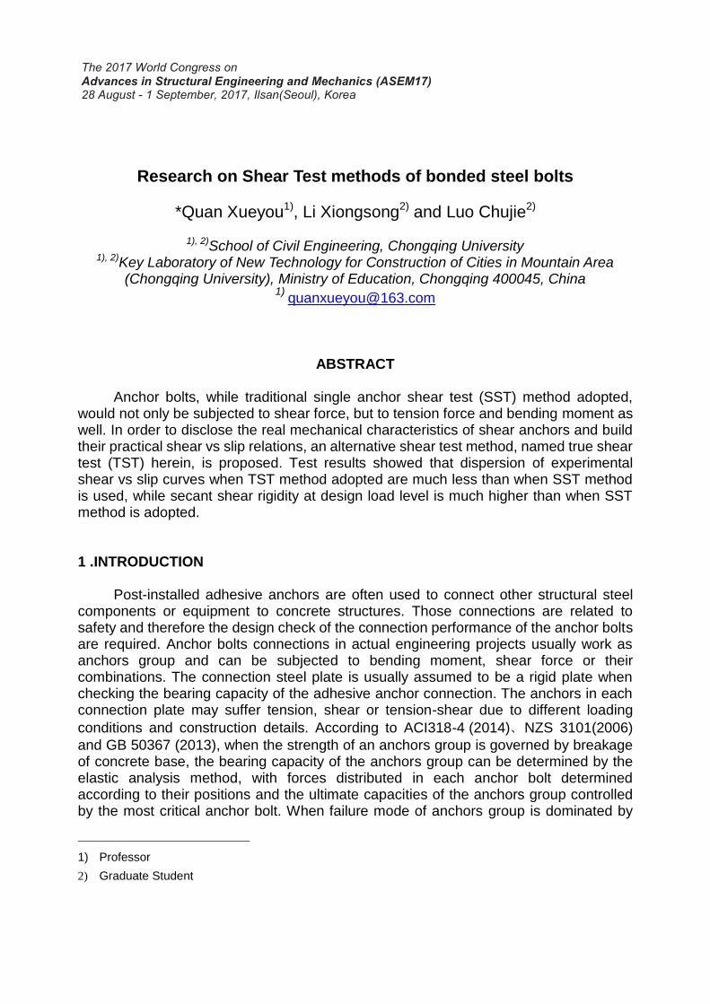
anchor bolt is specified, and the shear-slip curve of the anchor is acquired in the shear test of a single anchor bolt. The shear test of a single anchor bolt can be characterized as in Fig.1, in which the loading force is not in line with the reaction from the bearing concrete and the loading plate would rotate. When shear force is exerted in the rear of the loading plate as a thrust (Fig.1 (a)), with the rotation of the loading plate, the line of loading force would be elevated and results in greater tension force in the anchor. According to the case described by Eligehausen (2006), the measured and numerical calculations showed that tension force in anchor bolt may reach 35-40% of the shear force when shear test is carried out with this single anchor bolt test method. It would be better as in Fig. 1 (b), because in this case the loading force line will not be elevated as
the loading plate rotates, so the rotation of the loading plate and the tension force in anchor bolt would be restricted, but still there is tension force in the shear tested anchor bolt.
(a) (b)
Fig. 1 Loadbearing mechanism of single anchor shear test
ACI318-4(2014)、NZS3101(2006)and GB50367(2013)and other design
specifications reflect the correlation between the shear capacity and tensile bearing capacity of an anchor bolt. This correlation can be simply stated as: when anchor bolt is subjected to tension force, its shear capacity would be decreased, and vice versa.
From the generation mechanism of tension force in the anchor bolt while the traditional single anchor shear test method is adopted, there are two ways to limit the development of tension force in the testing shear anchor. The first is to exert shear force in the front of the loading plate as a pull. The second is to use a larger length in the loading plate between the front edge and the center of the testing anchor, which would increase the resisting moment of the test system and decrease the tension force in the anchor.
However, there are anchor bolts that just be subjected to shear force in the anchors group, for instance, the anchor bolts in the compression zone of an anchors group connection. Anchors in bolted steel plate are also in a state of pure shear. Therefore, it is necessary to reconsider the anchor bolt shear test method to obtain a more accurate shear-slip relation.
Based on the traditional single anchor shear test method stated in E488 /
E488M-15(2010), this paper designs an improved test method that would eliminate
tension force in the testing anchor so as to create the same stress state of anchors as in real engineering projects.
3. IMPROVED TRUE SHEAR TEST METHOD
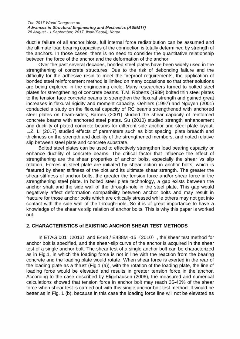
Since the traditional single anchor shear test (SST) would inevitably result in not only shear force, but also tension force in the testing anchor, and lead to inconsistence of stress state between shear testing anchor and shear anchor in construction field. So an improved shear test method shown in Fig. 2 could be considered. In the proposed test method shown in Fig. 2, if a test group contains a number of N anchor bolt specimens,
(a) Test series of shear anchors (b) True shear test method
Fig. 2 Improved shear test method for anchor bolts
N + 1 anchor bolts can be arranged in a concrete block in a straight line. When the shear test is performed for each anchor bolt from left to right, the nearest next test anchor is used as an auxiliary anchor bolt for the present testing anchor. The overturning moment formed by shear force attempts to rotate the loading plate, but the auxiliary anchor bolt turns to be tensioned to counteract the overturning moment so that the test anchor bolt only bears the shear force. A sliding structure is designed between the auxiliary anchor bolt and the loading plate, so the testing anchor may only bear shear force and the auxiliary bolt only be subjected to axial tensile force in the vertical direction. Because the testing anchor in this improved method would be in a stress state of true shear force, so it may be called a true shear test method (TST).
4. VERIFICATION TESTS
4.1 conception of the experimental tests 1) Testing anchor diameters As an exploratory test series, this paper
selected anchors of two different diameters, i.e., M12 and0, M2for the experimental tests. The difference of the diameters of the selected anchor bolts is large, which is helpful to evaluate the effectiveness of the test method.
2) Traditional single anchor shear test (SST) As an exploratory test series, this paper
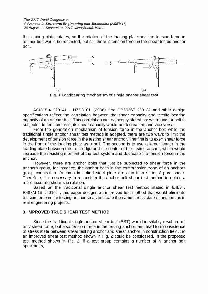
resorts to a methodology of comparison study, so traditional single anchor shear tests (SST) is taken as part of the test series. SST is performed according to the rules of E488 / E488M - 15 (2010). E488 / E488M-15 (2010) proposed the requirement of contact area between loading plate and concrete substrate, but it did not make a clear definition of this contact area. So in this paper, the loading plate contact area is defined as the area that is situated between
Test series of shear
anchors
Fig. 3 Definition of contact
area
Contact area
the front extremity of the loading plate and the center of the testing anchor, as shown in Fig. 3. According to E488 / E488M-15 (2010), for anchor bolts of diameter 12mm, the prescribed contact area is between 80 ~ 115 cm2. For anchor bolts of diameter 20mm, the prescribed contact area is between 115 ~ 160 cm2. In this experimental tests, the width of the loading plate is designed to be 175mm, so by a simple calculation, the length between the center of the testing anchor and the front edge of the loading plated was determined as 50mm for anchor bolts of diameter 12mm, and 80mm for anchor bolts of diameter 20mm, respectively. In addition, shear force was exerted by a pulling force in the front end of the loading plate so as to minimize tension force in the testing anchor.
3) true shear test (TST) In the proposed true shear test, from the second anchor to the last one of a test
series, the remaining anchor bolts need to be used as auxiliary bolts for the previous one. Therefore, it is necessary to determine a tension force limit for the auxiliary bolt and to confirm that the tension loading history of the auxiliary bolt does not affect the shear performance. For each diameter of the anchor bolts, two sets of true shear tests DUA1 and DUA2 have been designed separately. Anchors of test set DUA2 are all auxiliary anchor bolts corresponding to test set DUA1, so if the test results in a statistical sense show that the shear performance of test set DUA2 is basically the same as that of test set DUA1, it means that the performance of the auxiliary bolt in the proposed TST method would not be affected as long as the tension force in the auxiliary bolt is reasonably controlled.
4.2 Specimen design 1) Concrete specimen and anchor embedment depth In this paper, two concrete blocks were designed for shear tests of anchors M12
and M20. The traditional single anchor shear test and true shear test of each bolt diameter were conducted on the same concrete block. The concrete strength for both block were designed to be C30. All the anchors were full-threaded and had a performance level of 6.8. The design embedment depth of anchors in concrete is 8 times the nominal diameter of the anchor bolt, so the thickness of the concrete block was designed to be 200mm for anchors M12, and 300mm for anchors M20. The concrete blocks were reinforced with a small amount of reinforcing bars to reduce the risk of shrinkage cracking but kept the spacing large enough not to affect the shear performance of the anchors.
2) Tension control of auxiliary anchors In order to diminish the negative effect of tension force on the shear performance
of the auxiliary anchor bolt, the authors presupposed that the tension force of the auxiliary anchor is controlled within 10% of its calculated tension strength. The shear
strength, 𝑉𝑢𝑘 , and the tension strength, 𝑇𝑢𝑘, of the test anchors were calculated via Chinese design code GB 50367 (2013) , which was taken as the smaller value between what was dominated by the failure of anchor material and by the failure of bearing concrete. The overturning moment applied by the loading system is equal to shear force multiplied by the distance from the shear force to the concrete surface (reference to Fig. 1). The tension force of the auxiliary bolt is approximately calculated and controlled as in Eq. (1)
T = V𝑢𝑘 ∙ a/s < 0.1𝑇𝑢𝑘 (1)
Where s is the center distance between the shear bolt and the auxiliary bolt (reference to Fig. 2).
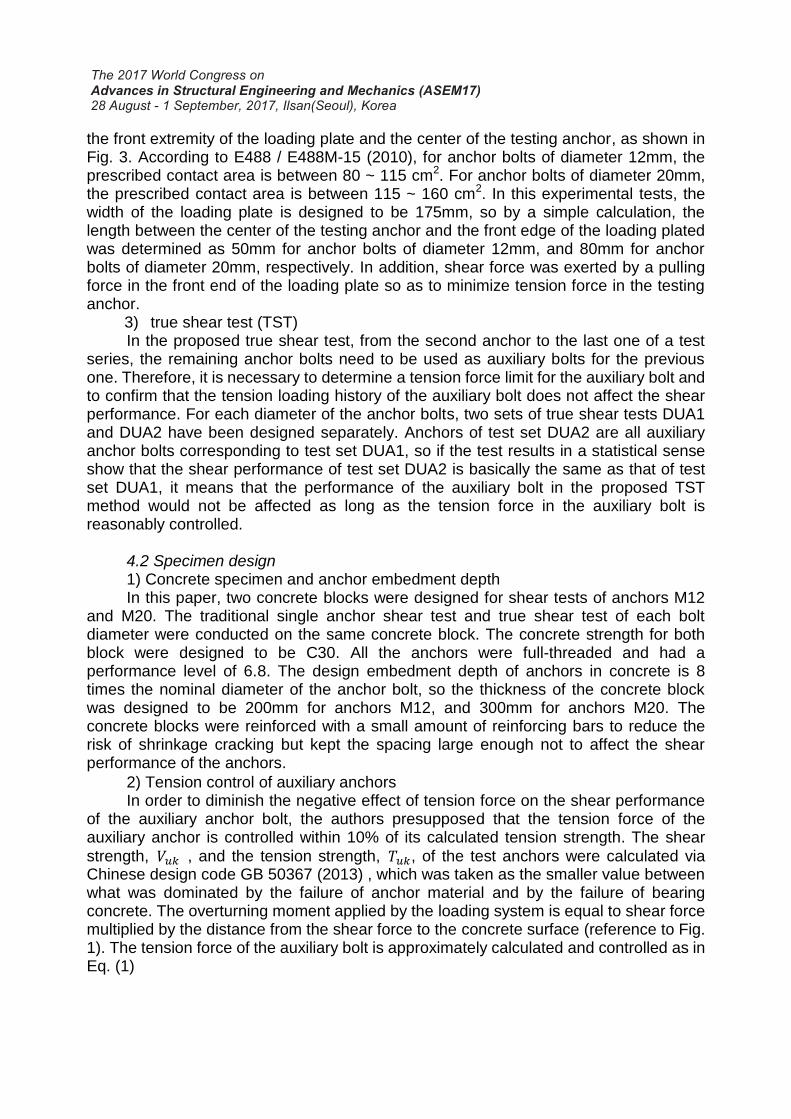
3) Arrangement of anchor bolts Anchors arrangement is as shown in Fig. 4. Anchor spacing and edge distance
were determined as 200mm, which is conformed to the requirements of Chinese design code GB 50367 (2013). Anchors for diameter M12 and M20 have the same arrangement on two different concrete block, respectively.
On each concrete block, distributed are test sets SIN1, SIN2, which are two sets of single anchor shear test series, test set DUA1, which is a test set of TST anchor specimens gone through shear test without a tension loading history, DUA2, a set of TST anchor specimens having tension loading history as auxiliary anchor for DUA1 before gone through shear test, test set REC, author’s proposed true shear test set, in which every testing anchor, except the first one, is the auxiliary anchor for the one before it.
4.3 Test methods 1) Loading system Before testing, a pre-load of 5% the estimated ultimate shear strength was acted
on the test system so as to certify the normal state of the system, and make the test
Fig. 4 Arrangement of test sets of shear anchors

system in close contact with various parts. All tests were carried out in a monotonous loading history. According to E488 / E488M-15(2010), from the start to the end of the test, the loading time history was controlled within 2 to 3 minutes.
Fig. 5 shows the testing scenarios. In the picture, it can be seen that the horizontal shear force is provided by a center-through hydraulic jack and controlled by a pressure sensor. The load is conveyed by two parallel screw rods so as to avoid obstruction of other anchors on the same line.
2) Test measurements The experimental test focuses on the measurement of anchor’s shear-slip
relations. At the rear end of the loading plate, two LVDTs with a precision of 0.01 mm are arranged symmetrical to the testing anchor along the shear force direction. The slip value under each load is taken as the average of the two LVDTs’ displacement measurements.
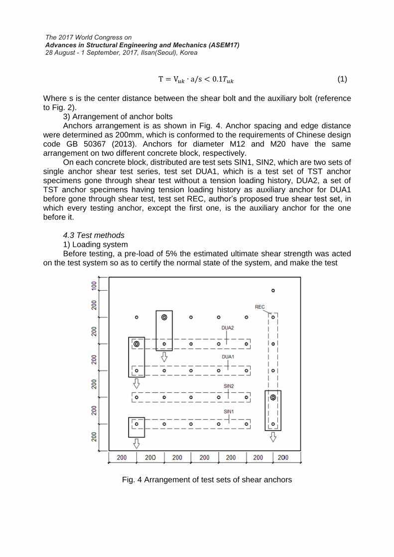
4.4 Test results 1) Traditional single anchor shear test (SST) Fig. 6 shows the measured shear-slip relation for all the SST anchors of diameter
M12 and M20. As can be seen in the figure, measured shear-slip curves have a great dispersion.
Fig. 5 Testing scenarios
Jack
Load displacement
PTFE
LVDT Roller device
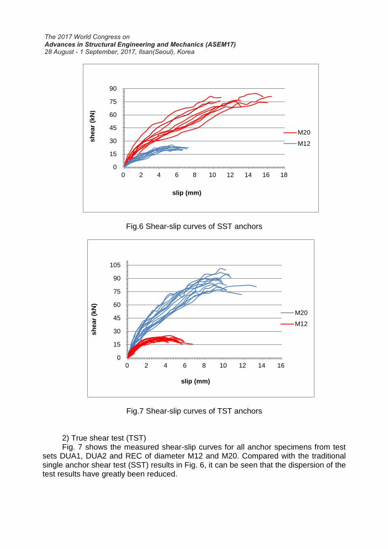
Fig.6 Shear-slip curves of SST anchors
Fig.7 Shear-slip curves of TST anchors
2) True shear test (TST) Fig. 7 shows the measured shear-slip curves for all anchor specimens from test
sets DUA1, DUA2 and REC of diameter M12 and M20. Compared with the traditional single anchor shear test (SST) results in Fig. 6, it can be seen that the dispersion of the test results have greatly been reduced.
0
15
30
45
60
75
90
0 2 4 6 8 10 12 14 16 18
sh
ear
(kN
)
slip (mm)
M20
M12
0
15
30
45
60
75
90
105
0 2 4 6 8 10 12 14 16
sh
ear
(kN
)
slip (mm)
M20
M12
(a) Curves for M12
(b) Curves for M20
Fig. 8 Regression curves
5. TEST RESULTS ANALYSIS 5.1 The Negligible Effect of Tension History on the Shear Performance In the conception for the TST series, it has been supposed that tension history of
test anchors would not negatively affect their shear performance so long as tension force were kept within a reasonable limit. In this paper, tension force of test anchors were controlled no more than 10% their design tension strength.
0
20
40
60
80
100
0 2 4 6 8 10 12
sh
ear(
KN
)
slip (mm)
M20 Comparison of All Groups SIN
DUA1
DUA2
REC1
SINSECANT
0
5
10
15
20
25
0 1 2 3 4 5 6 7 8
sh
ear(
kN)
slip(mm)
M12 Comparison of All Groups SIN
DUA1
DUA2
REC1
SINSECANTDUA1SECANTDUA2SECANT
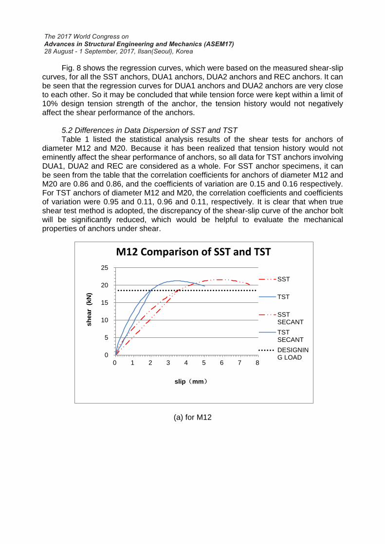
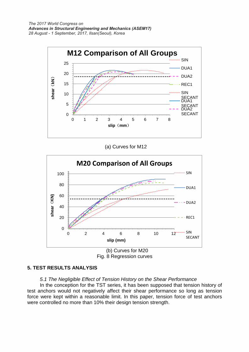
Fig. 8 shows the regression curves, which were based on the measured shear-slip curves, for all the SST anchors, DUA1 anchors, DUA2 anchors and REC anchors. It can be seen that the regression curves for DUA1 anchors and DUA2 anchors are very close to each other. So it may be concluded that while tension force were kept within a limit of 10% design tension strength of the anchor, the tension history would not negatively affect the shear performance of the anchors.
5.2 Differences in Data Dispersion of SST and TST Table 1 listed the statistical analysis results of the shear tests for anchors of
diameter M12 and M20. Because it has been realized that tension history would not eminently affect the shear performance of anchors, so all data for TST anchors involving DUA1, DUA2 and REC are considered as a whole. For SST anchor specimens, it can be seen from the table that the correlation coefficients for anchors of diameter M12 and M20 are 0.86 and 0.86, and the coefficients of variation are 0.15 and 0.16 respectively. For TST anchors of diameter M12 and M20, the correlation coefficients and coefficients of variation were 0.95 and 0.11, 0.96 and 0.11, respectively. It is clear that when true shear test method is adopted, the discrepancy of the shear-slip curve of the anchor bolt will be significantly reduced, which would be helpful to evaluate the mechanical properties of anchors under shear.
(a) for M12
0
5
10
15
20
25
0 1 2 3 4 5 6 7 8
sh
ear
(kN
)
slip(mm)
M12 Comparison of SST and TST
SST
TST
SSTSECANT
TSTSECANT
DESIGNING LOAD
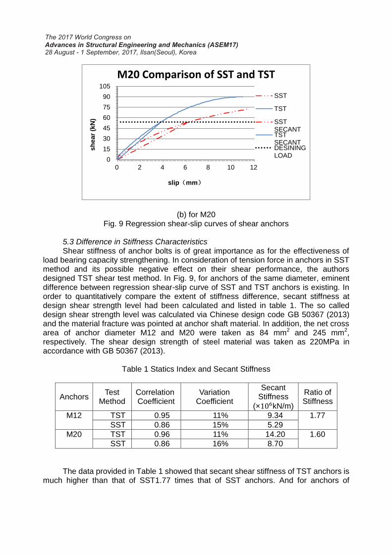
(b) for M20 Fig. 9 Regression shear-slip curves of shear anchors
5.3 Difference in Stiffness Characteristics Shear stiffness of anchor bolts is of great importance as for the effectiveness of
load bearing capacity strengthening. In consideration of tension force in anchors in SST method and its possible negative effect on their shear performance, the authors designed TST shear test method. In Fig. 9, for anchors of the same diameter, eminent difference between regression shear-slip curve of SST and TST anchors is existing. In order to quantitatively compare the extent of stiffness difference, secant stiffness at design shear strength level had been calculated and listed in table 1. The so called design shear strength level was calculated via Chinese design code GB 50367 (2013) and the material fracture was pointed at anchor shaft material. In addition, the net cross area of anchor diameter M12 and M20 were taken as 84 mm2 and 245 mm2, respectively. The shear design strength of steel material was taken as 220MPa in accordance with GB 50367 (2013).
Table 1 Statics Index and Secant Stiffness
Anchors Test
Method Correlation Coefficient
Variation Coefficient
Secant Stiffness
(×106kN/m)
Ratio of Stiffness
M12 TST 0.95 11% 9.34 1.77
SST 0.86 15% 5.29
M20 TST 0.96 11% 14.20 1.60
SST 0.86 16% 8.70
The data provided in Table 1 showed that secant shear stiffness of TST anchors is
much higher than that of SST1.77 times that of SST anchors. And for anchors of
0
15
30
45
60
75
90
105
0 2 4 6 8 10 12
sh
ear
(kN
)
slip(mm)
M20 Comparison of SST and TST
SST
TST
SSTSECANTTSTSECANTDESININGLOAD
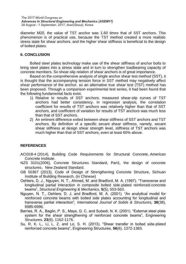
diameter M20, the value of TST anchor was 1.60 times that of SST anchors. This phenomenon is of practical use, because the TST method created a more realistic stress state for shear anchors, and the higher shear stiffness is beneficial to the design of bolted plates.
6. CONCLUSION
Bolted steel plates technology make use of the shear stiffness of anchor bolts to
bring steel plates into a stress state and in turn to strengthen loadbearing capacity of concrete members. So shear-slip relation of shear anchors is of great importance.
Based on the comprehensive analysis of single anchor shear test method (SST), it is thought that the accompanying tension force in SST method may negatively affect shear performance of the anchor, so an alternative true shear test (TST) method has been proposed. Through a comparison experimental test series, it had been found that the following fundamental facts exist.
1) Relative to results of SST anchors, measured shear-slip curves of TST anchors had better consistency. In regression analysis, the correlation coefficient for results of TST anchors was relatively higher than that of SST anchors, and coefficient of variation for results of TST anchors was much less than that of SST anchors.
2) An eminent difference exited between shear stiffness of SST anchors and TST anchors. By definition of a specific secant shear stiffness, namely, secant shear stiffness at design shear strength level, stiffness of TST anchors was much higher than that of SST anchors, even at least 60% above.
REFERENCES ACI318-4 (2014), Building Code Requirements for Structural Concrete, American
Concrete Institute. NZS 3101(2006), Concrete Structures Standard, Part1, the design of concrete
structures,New Zealand Standard.
GB 50367 (2013), Code of Design of Strengthening Concrete Structure, Sichuan Institute of Building Research. (in Chinese)
Oehlers, D. J., Nguyen, N. T., Ahmed, M. and Bradford, M. A. (1997). “Transverse and longitudinal partial interaction in composite bolted side-plated reinforced-concrete beams”, Structural Engineering & Mechanics, 5(5), 553-563.
Nguyen, N. T., Oehlers, D. J. and Bradford, M. A. (2001). “An analytical model for reinforced concrete beams with bolted side plates accounting for longitudinal and transverse partial interaction”, International Journal of Solids & Structures, 38(38), 6985-6996.
Barnes, R. A., Baglin, P. S., Mays, G. C. and Subedi, N. K. (2001). “External steel plate system for the shear strengthening of reinforced concrete beams”, Engineering Structures, 23(9), 1162-1176.
Su, R. K. L., Li, L. Z. and Lo, S. H. (2013). “Shear transfer in bolted side-plated reinforced concrete beams”, Engineering Structures, 56(6), 1372-1383.
Su, R. K. L., Siu, W. H. and Smith, S. T. (2010). “Effects of bolt–plate arrangements on steel plate strengthened reinforced concrete beams”, Engineering Structures, 32(6), 1769-1778.
ETAG 001(2013), Guideline for European Technical Approval of Metal Anchors for Use
in Concrete,European Organization for Technical Approvals.
E488/E488M-15(2010) Standard Test Methods for Strength of Anchors Concrete
Elements,ASTM Committee.
Eligehausen, R., Mallée, R. and Silva, J. F. (2006), Anchorage in concrete construction, Ernst & Sohn.
GB 50010 (2010). Code of Design of Concrete Structure, China Academy of Building Research. (in Chinese)
Roberts, T. M., & Haji-Kazemi, H. (1989). “Strengthening of under-reinforced concrete beams with mechanically attached steel plates”, International Journal of Cement Composites & Lightweight Concrete,11(1), 21,27-21,27.
Li, L. Z., Cai, Z. W., Lu, Z. D., Zhang, X. L., & Wang, L. (2017). “Shear performance of bolted side-plated reinforced concrete beams”, Engineering Structures, 144, 73-87.