research laboratory surface fatigue lives of case ... · surface fatigue lives of case-carburized...
TRANSCRIPT

NASA/TM--2000-210044
RESEARCH LABORATORY
ARL-TR-2170
DETC2000 / PTG-14373
Surface Fatigue Lives of Case-Carburized
Gears With an Improved Surface Finish
T.L. Krantz
U.S. Army Research Laboratory, Glenn Research Center, Cleveland, Ohio
M.P. Alanou, H.P. Evans, and R.W. Snidle
Cardiff University, Wales, United Kingdom
April 2000
https://ntrs.nasa.gov/search.jsp?R=20000054668 2018-07-03T12:02:52+00:00Z

The NASA STI Program Office... in Profile
Since its founding, NASA has been dedicated tothe advancement of aeronautics and spacescience. The NASA Scientific and Technical
Information (STI) Program Office plays a key part
in helping NASA maintain this important role.
The NASA STI Program Office is operated by
Langley Research Center, the Lead Center forNASA's scientific and technical information. The
NASA ST[ Program Office provides access to the
NASA STI Database, the largest collection of
aeronautical and space science STI in the world.The Program Office is also NASA's institutional
mechanism for disseminating the results of itsresearch and development activities. These results
are published by NASA in the NASA STI ReportSeries, which includes the following report types:
TECHNICAL PUBLICATION. Reports of
completed research or a major significant
phase of research that present the results of
NASA programs and include extensive dataor theoretical analysis. Includes compilations
of significant scientific and technical data andinformation deemed to be of continuing
reference value. NASA's counterpart of peer-
reviewed formal professional papers but
has less stringent limitations on manuscript
length and extent of graphic presentations.
TECHNICAL MEMORANDUM. Scientific
and technical findings that are preliminary or
of specialized interest, e.g., quick release
reports, working papers, and bibliographiesthat contain minimal annotation. Does not
contain extensive analysis.
CONTRACTOR REPORT. Scientific and
technical findings by NASA-sponsoredcontractors and grantees.
CONFERENCE PUBLICATION. Collected
papers from scientific and technical
conferences, symposia, seminars, or other
meetings sponsored or cosponsored byNASA.
SPECIAL PUBLICATION. Scientific,
technical, or historical information from
NASA programs, projects, and missions,often concerned with subjects having
substantial public interest.
TECHNICAL TRANSLATION. English-
language translations of foreign scientific
and technical material pertinent to NASA'smission.
Specialized services that complement the STIProgram Office's diverse offerings include
creating custom thesauri, building customizeddata bases, organizing and publishing research
results.., even providing videos.
For more information about the NASA STI
Program Office, see the following:
• Access the NASA STI Program Home Page
at http'//www.sti.nasa.gov
• E-mail your question via the Internet to
• Fax your question to the NASA Access
Help Desk at (301) 621-0134
• Telephone the NASA Access Help Desk at(301) 621-0390
Write to:
NASA Access Help Desk
NASA Center for AeroSpace Information7121 Standard Drive
Hanover, MD 21076

NASA/TMm2000-210044
U.S. ARMY
RESEARCH LABORATORY
ARL-TR-2170
DETC2000 / PTG-14373
Surface Fatigue Lives of Case-Carburized
Gears With an Improved Surface Finish
T.L. Krantz
U.S. Army Research Laboratory, Glenn Research Center, Cleveland, Ohio
M.P. Alanou, H.P. Evans, and R.W. Snidle
Cardiff University, Wales, United Kingdom
Prepared for the
2000 Design Engineering Technical Conferences and Computers and
Information in Engineering Conference
sponsored by the American Society of Mechanical Engineers
Baltimore, Maryland, September 10-13, 2000
National Aeronautics and
Space Administration
Glenn Research Center
April 2000

Acknowledgments
The work reported was supported by the U.S. Arm), European Research Office, the U.S. Army Research Lab, andthe NASA Rotorcraft Base Program, to whom we are most grateful. We also thank Mr. Rob Frazer of Newcastle
University Design Unit for completion of gear metrology and Mr. J. David Cogdell of the Timken Company
for providing inspection data from a mapping interferometric microscope. We thank Mr. Dennis Towmsend,
now retired from NASA, for his guidance and support of this project.
This report is a preprint of a paper intended for presentation at a conference. Because
of changes that may be made before formal publication, this preprint is made
available with the understanding that it will not be cited or reproduced without the
permission of the author.
NASA Center for Aerospace Information7121 Standard Drive
Hanover, MD 21076
Price Code: A03
Available from
National Technical Information Service
5285 Port Royal Road
Springfield, VA 22100Price Code: A03

SURFACE FATIGUE LIVES OF CASE-CARBURIZED GEARS WITH AN IMPROVED SURFACE FINISH
T.L. Krantz
U.S. Army Research LaboratoryGlenn Research CenterCleveland, Ohio 44135
M.P. Alanou, H.P. Evans, and R.W. SnidleCardiff University
P.O. Box 685Cardiff, CF24 3TA
Wales, United Kingdom
Previous research provides qualitative evidence that an improved
surface finish can increase the surface fatigue lives of gears. To quantify
the influence of surface roughness on life, a set of AISI 9310 steel gears
was provided with a near-mirror finish by superfinishing. The effects of
the superfinishing on the quality of the gear tooth surfaces were deter-
mined using data from metrology, profilometry, and interferometric
microscope inspections. The superfinishing reduced the roughness
average by about a factor of 5. The superfinished gears were subjected to
surface fatigue testing at 1.71-GPa (248-ksi) Hertz contact stress, and
the data were compared with the NASA Glenn gear fatigue data base.
The lives of gears with superfinished teeth were about four times greater
compared with the lives of gears with ground teeth but with otherwise
similar quality.
INTRODUCTION
The power density of a gearbox is an important consideration for
many applications and is especially important for gearboxes used on air-
craft. One factor that limits gearbox power density is the ability of the
gear teeth to transmit power for the required number of cycles without
pitting or spalling. Economical methods for improving surface fatigue
lives of gears are therefore highly desirable.
Tests of rolling element bearings [ 1,2 for example] have shown that
the bearing life is affected by the calculated elastohydrodynamic lubri-
cant (EHL) film thickness. When the specific film thickness (the EHL
film thickness divided by the composite surface roughness) is less than
unity, the service life of the bearing is considerably reduced. Some
investigators have anticipated that the effect of specific film thickness on
gear life could be even more pronounced than the effect on bearing life
[3]. To improve the surface fatigue lives of gears, the EHL film thickness
may be increased, the composite surface roughness reduced, or both
approaches may be adopted. These two effects have been studied.
Townsend and Shimski [3] studied the influence of seven different
lubricants of varying viscosity on gear fatigue lives. Tests were conducted
on a set of case-carburized and ground gears, all manufactured from the
same melt of consumable-electrode vacuum-melted (CVM) AISI 9310
steel. At least 17 gears were tested with each lubricant. They_ noted a
strong positive correlation of the gear surface fatigue lives with the cal-
culated EHL film thickness and demonstrated that increasing the EHL
film thickness does indeed improve gear surface fatigue life.
At least three investigations have been carried out to demonstrate
the relation between gear surface fatigue and surface roughness. One
investigation by Tanka, et al. [4] involved a series of tests conducted on
steels of various chemistD', hardness, and states of surface finish. Some
gears were provided with a near-mirror finish by using a special grinding
wheel and machine [5]. The grinding procedure was a generating pro-
cess that provided teeth with surface roughness quantified as Rma x of
about 0.1 lam (4 Bin.). A series of pitting durability tests were conducted
and included tests of case-carburized pinions mating with both plain car-
bon steel gears and through-hardened steel gears. They concluded that
the gear surface durability was improved in all cases as a result of the
near-mirror finish. They noted that when a case-hardened, mirror-
finished pinion was mated with a relatively soft gear, the gear became
polished with running. They considered that this polishing during run-
ning improved the surface durability of the gear. None of the tests con-
ducted in the study, however, included a case-carburized pinion mated
with a case-carburized gear.
A second investigation by Nakasuji, et al. [6,7] studied the possibil-
ity of improving gear fatigue lives by electrolytically polishing the teeth.
They conducted their tests using medium carbon steel gears and noted
that the electropolishing process altered the gear profile and the surface
hardness as well as the surface roughness. The polishing reduced the
surface hardness and changed the tooth profiles to the extent that the
measured dynamic tooth stresses were significantly larger relative to the
ground gears. Even though the loss of hardness and increased dynamic
stresses would tend to reduce stress limits for pitting durability, the elec-
trolytic polishing was shown to improve the stress limit, at which the
gears were free of pitting, by about 50 percent.
Hoyashita, et al. [8,9] completed a third investigation of the relation
between surface durability and roughness. They conducted a set of tests
to investigate the effects of shot peening and polishing on the fatigue
strength of case-hardened rollers. Some of the shot-peened rollers were
reground and some were polished by a process called barrelling. The
reground rollers had a roughness average (Ra) of 0.78 lam (31 lain.). The
polished rollers had a Ra of 0.05/am (2.0 lain.). Pitting tests were con-
ducted using a slide-roll ratio of -20 percent on the follower with min-
eral oil as the lubricant. The lubricant film thickness was estimated to be
0.15 - 0.25 Bm (5.9 - 9.8 lain.). The surface durability of the rollers that
had been shot peened and polished by barrelling was significantly
improved compared with rollers that were shot peened only or that were
NASA/TM--2000-210044 1

shotpeenedandreground.Theyfoundthatthepittinglimits(maximumHertzstresswithnopittingafter107cycles)oftheshot-peened/regroundrollersandtheshot-peened/polishedrollerswere2.15GPa(312ksi)and2.45GPa(355ksi),respectively.
Patching,etal.[10]evaluatedthescuffingpropertiesofgroundandsuperfinishedsurfacesusingturbineengineoilasthelubricant.Theevalu-ationwasperformedusingcase-carburizedsteeldiscs.Thediscswerefinishgroundintheaxialdirectionsuchthattheorientationoftherough-nesswouldbeperpendiculartothedirectionofrollingandsliding,therebysimulatingtheconditionsnormallyfoundingears.Someofthediscsweresuperfinishedtoprovidesmoothersurfaces.TheRaofthegrounddiscswasabout0.4lam(16lain.),andtheRaofthesuperfinisheddiscswaslessthan0.1lam(4_in.).Theyfoundthatcomparedwiththegrounddiscs,thesuperfinisheddiscshadasignificantlyhigherscuffingloadcapacitywhenlubricatedwithturbineengineoilandsubjectedtorela-tivelyhighrollingandslidingspeeds.Theyalsonotedthatundertheseoperatingconditions,theslidingfrictionofthesuperfinishedsurfaceswastheorderofhalfthatforthegroundsurfaces.
Thesepreviousworks[1-10]providestrongevidencethatthereductionofsurfaceroughnessimprovesthelubricatingconditionandoffersthepossibilityofincreasingthesurfacefatiguelivesofgears.How-ever,thereislittlepublisheddatatoquantifytheimprovementinlifeforcase-carburizedgears.Thepresentstudywasthereforecarriedouttoquantifythesurfacefatiguelivesofaerospace-qualitygearsthathavebeenprovidedwithanimprovedsurfacefinishrelativetoconventionallygroundgears.
TEST APPARATUS, SPECIMENS, AND PROCEDURE
Gear Test Apparatus
The gear fatigue tests were performed in the NASA Glenn Research
Center's gear test apparatus. The test rig is shown in Fig. l(a) and
described in reference [l l]. The rig uses the four-square principle of
applying test loads so that the input drive only needs to overcome the
frictional losses in the system. The test rig is belt driven and operated at
a fixed speed for the duration of a particular test.
A schematic of the apparatus is shown in Fig. l (b). Oil pressure and
leakage replacement flow is supplied to the load vanes through a shaft
seal. As the oil pressure is increased on the load vanes located inside one
of the slave gears, torque is applied to it_ shaft. This torque is transmitted
through the test gears and back to the slave gears, In this way power is
recirculated and the desired load and corresponding stress level on the
test gear teeth may be obtained by adjusting the hydraulic pressure. The
two identical test gears may be started under no load, and the load can
then be applied gradually. This arrangement also has the advantage that
changes in load do not affect the width or position of the running track
on the gear teeth. The gears are tested with the faces offset as shown in
Fig. 1. By utilizing the offset arrangement for both faces of the gear
teeth, a total of four surface fatigue tests can therefore be run for each
pair of gears.
Separate lubrication systems are provided for the test and slave gears.
The two lubrication systems are separated at the gearbox shafts by
pressurized labyrinth seals, with nitrogen as the seal gas. The test gear
lubricant is filtered through a 5-lam (200-lain.) nominal fiberglass filter.
A vibration transducer mounted on the gearbox is used to automatically
stop the test rig when gear surface fatigue damage occurs. The gearbox
is also automatically stopped if there is a loss of oil flow to either the
slave gearbox or the test gears, if the test gear oil overheats, or if there is
a loss of seal gas pressurization.
T96t Specimens
The gears of the present study were manufactured from air-melt-
vacuum arc-remehed (AM-VAR) AISI 9310 steel. The currently avail-
able baseline for this study is a set of conventionally ground gears that
were previously tested and the data reported [ 12]. The test gears used for
the baseline study of Ref. 12 were manufactured from consumable-elec-
trode vacuum-melted (CVM) AIS19310 steel. The AM-VAR and CVM
processing are essentially equivalent [13,14]. Both sets of gears were
case carburized and ground. The nominal and certified chemical compo-
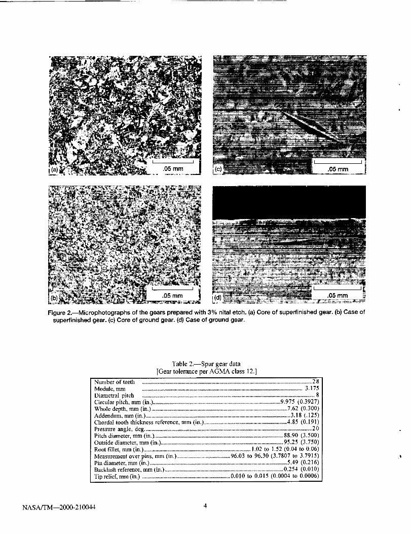
sitions of the gears are given in Table 1. Figures 2(a) to (d) are photomi-
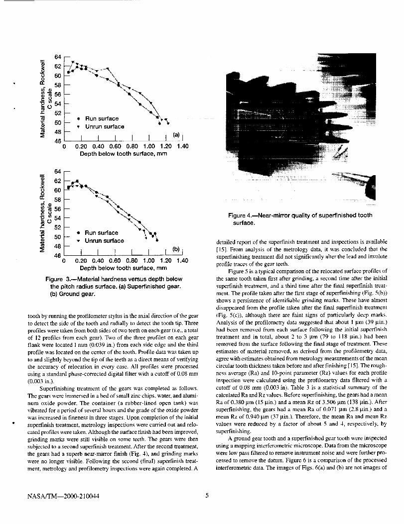
crographs showing the microstructure of the case and core. Figure 3 is a
plot of material hardness versus depth below the pitch radius surface.
The data of Fig. 3 are equivalent Rockwell C scale hardness values con-
verted from Knoop microhardness data. These data and metrology
inspections [15] veri_' that the gear materials and geometry are aero-
space quality.
The dimensions of the gears are given in Table 2. The gears are
3.175 mm module (8 diametral pitch) and have a standard 20 ° involute
pressure angle with tip relief of 0.013 mm (0.0005 in.) starting at the
highest point of single tooth contact. The gears have a nominal
0.13-mm- (0.005-in.-) radius edge break to avoid edge loading.
Fourteen AM-VAR gears were selected for finishing by a polishing
method described below. A subset of four AM-VAR gears was selected
at random for metrology inspections, both before and after superfmishing.
Parameters measured on each gear included lead and profile errors, adja-
cent pitch errors, and mean circular tooth thickness. In order to show the
detailed effects of superfinishing, it was decided to also take "relocated"
profiles from the gear teeth. This was achieved by use of a special step-
per-motor-driven profilometer with which it was possible to take a pro-
file or series of profiles at a precisely known location on a gear tooth.
The principle of relocation was based on detection of the edges of the
Table 1.--Nominal and certified chemical composition of _ear materials, AISI 93 t0
Nominal contents, wt %
Ground gear,certified contents, v,t %
Superfinished gear,certified contents, wt %
*Indicates not measured.
Element
C Mn P S Si Ni Mo Cr Cu Fe
0. I0 0.63 0.005 0.005 0.27 3.22 0.12 t.21 0.13 Balance
0.10 0.56 0.003 0.003 0.26 3.49 0.10 1.15 * *
0.11 0.55 0.006 0.018 '"0.26 3.42 0.10 1.30 * *
NASA/TM--2000-210044 2

Oil-seal gas flow -7t
Viewing port-
Test-gear cover 7
,- Slave-systemoil inlet
Drive
shaft 7I
Shaft!
I oil seal
(a)
Test-
lubricant. "inlet _./
Test-lubricant/
outlet temperature /measurement location -J
Load jpressure
Loading vane
Slave gear_- Oil seal
Nonactuating
r- Test slave gear
gears-7 _ Drive shaftFt .................. j_] _ _ / Belt pulley
>_ _: ___;_ _W-_ _:_:-_ .... _ ...........
....... Slave-geartorque
Loading van_-_
Shaft Load _,_':,',
pressure \_' _j seal - -__-_I Actuating _ A Shaft \_
Offset slave gear _ torqueView
(b) A-A
Figure 1.--NASA Glenn Research Center gear fatigue test apparatus. (a) Cutaway view.(Io)Schematic view.
NASA/TM--2000-210044 3
!i !
_!'___ I 05 mm
.05 mm
Figure 2._Microphotographs of the gears prepared with 3% nital etch. (a) Core of superfinished gear. (b) Case of
superflnished gear. (c) Core of ground gear. (d) Case of ground gear.
Table 2.--Spur gear data
[Gear tolerance per AGMA class 12.]
Number of teeth ............................................................................................................................. 2 8Module, mm ...................................................................................................................... 3.175
Diametral pitch ............................................................................................................................... 8
Circular pitch, mm (in.) .............................................................................................. 9.975 (0.3927)
Whole depth, mm (in.) .................................................................................................... 7.62 (0.300)Addendum, mm (in.) .......................................................................................................... 3.18 (.125)
Chordal tooth thickness reference, mm (in.) ............................................................. 4.85 (0.191)
Pressure angle, deg ........................................................................................................................... 2 0Pitch diameter, mm (in.) ............................................................................................... 88.90 (3.500)
Outside diameter, mm (in.) .......................................................................................... 95.25 (3.750)
Root fillet, mm (in.) ............................................................................... 1.02 to 1.52 (0.04 to 0.06)
Measurement over pins, mm (in.) ....................................... 96.03 to 96,30 (3.7807 to 3.7915)
Pin diameter, mm (in.) ..................................................................................................... 5.49 (0.216)Backlash reference, mm (in.) ....................................................................................... 0.254 (0.010)
Tip relief, nun (in.) ................................................................. 0.010 to 0.015 (0.0004 to 0.0006)
NASA/TM--2000-210044 4
0_
¢DO
re
t'-
"E
64
62
60
58
0 54
52
50
48
48
m
/
• Unrun surface
I 1 I I I I0 0.20 0.40 0.60 0.80 1.00 1.20
Depth below tooth surface, mm
(a) I
1.40
64
6260
O
0: 58
_56
=__54
_" 52
"= 50a)
"_ 48
46
?
_ = Run surface,, Unrun surface
i I I l i L%0 0.20 0.40 0.60 0.80 1.00 1.20 1.40
Depth below tooth surface, mm
Figure 3.--Material hardness versus depth belowthe pitch radius surface. (a) Superfinished gear.
(b) Ground gear.
tooth by running the profilometer stylus in the axial direction of the gear
to detect the side of the tooth and radially to detect the tooth tip. Three
profiles were taken from both sides of two teeth on each gear (i.e., a total
of 12 profiles from each gear). Two of the three profiles on each gear
flank were located 1 mm (0.039 in.) from each side edge and the third
profile was located on the center of the tooth. Profile data was taken up
to and slightly beyond the tip of the teeth as a direct means of verifying
the accuracy of relocation in every case. All profiles were processed
using a standard phase-corrected digital filter with a cutoff of 0.08 mm
(0.003 in.).
Superfinishing treatment of the gears was completed as follows.
The gears were immersed in a bed of small zinc chips, water, and alumi-
num oxide powder. The container (a rubber-lined open tank) was
vibrated for a period of several hours and the grade of the oxide powder
was increased in fineness in three stages. Upon completion of the initial
superfinish treatment, metrology inspections were carried out and relo-
cated profiles were taken. Although the surface f'mish had been improved,
grinding marks were still visible on some teeth. The gears were then
subjected to a second superfinish treatment. After the second treatment,
the gears had a superb near-mirror finish (Fig. 4), and grinding marks
were no longer visible. Following the second (final) superfinish treat-
ment, metrology and profilometry inspections were again completed. A
Figure 4.--Near-mirror quality of superfinished toothsurface.
detailed report of the superfinish treatment and inspections is available
[15]. From analysis of the metrology data, it was concluded that the
superfinishing treatment did not significantly alter the lead and involute
profile traces of the gear teeth.
Figure 5 is a typical comparison of the relocated surface profiles of
the same tooth taken first after grinding, a second time after the initial
superfinish treatment, and a third time after the final superfinish treat-
ment. The profile taken after the first stage of superfinishing (Fig. 5(b))
shows a persistence of identifiable grinding marks. These have almost
disappeared from the profile taken after the final superfinish treatment
(Fig. 5(c)), although there are faint signs of particularly deep marks.
Analysis of the profilometr), data suggested that about I lam (39 lain.)
had been removed from each surface following the initial superfinish
treatment and in total, about 2 to 3 pm (79 to 118 lain.) had been
removed from the surface following the final stage of treatment. These
estimates of material removed, as derived from the profilometry data,
agree with estimates obtained from metrology measurements of the mean
circular tooth thickness taken before and after finishing [15]. The rough-
ness average (Ra) and 10-point parameter (Rz) values for each profile
inspection were calculated using the profilometry data filtered with a
cutoff of 0.08 mm (0.003 in). Table 3 is a statistical summary of the
calculated Ra and Rz values. Before superfinishing, the gears had a mean
Ra of 0.380 lam (15 lain.) and a mean Rz of 3.506 pm (138 lain.). After
superfinishing, the gears had a mean Ra of 0.071 lam (2.8 lain.) and a
mean Rz of 0.940 lam (37 lain.). Therefore, the mean Ra and mean Rz
values were reduced by a factor of about 5 and 4, respectively, by
superfinishing.
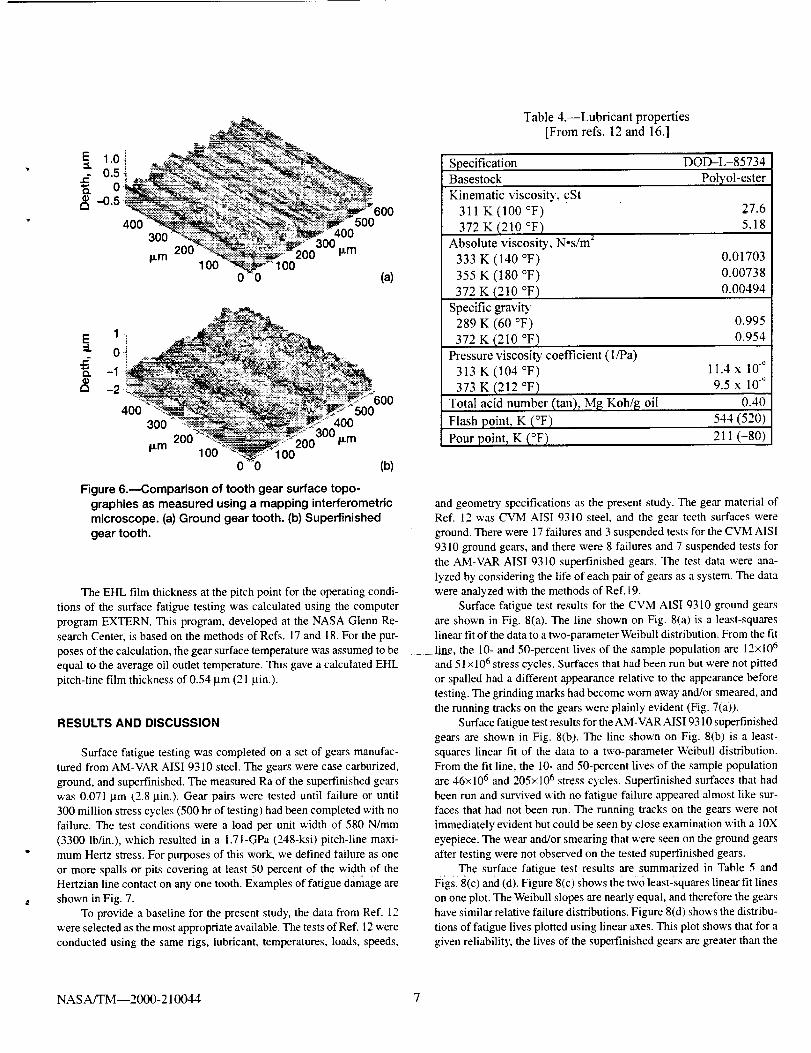
A ground gear tooth and a superfinished gear tooth were inspected
using a mapping interferometric microscope. Data from the microscope
were low pass filtered to remove instrument noise and were further pro-
cessed to remove the datum. Figure 6 is a comparison of the processed
interferometric data. The images of Figs. 6(a) and (b) are not images of
NASA/TM--2000-210044 5

A,& A(a)
AA_(b)
_'_'_'*__ _'_'_v'_*_*'_'_v_=_'_'_''_-_. _ .:i_1 i_m
A A
(c) 100 Fm
Figure 5.--Typical relocated surface features measured using a profilometer
followed by filtering of the data using a 0.08-mm (o.o03-in.) cutoff. Evidence of
persistence of the deepest grinding marks are indicated by arrows. (a) Ground
tooth surface, Ra = 0.434 i.tm (17 _in.). (b) Same tooth surface after the first
stage of superfinishing, Ra = 0.083 p.m (3.3 _in.). (c) Same tooth after second
(final) stage of superfinishing, Ra = 0.056 Ixm (2.2 ixin.).
Table 3.--Summary of statistical analysis of profilometry data
Parameter Surface condition
Roughness average
(Ra)
10-point parameter
Before superf'm!shin_;
After superfinished
Before superfinishin_
Mean value, Standard deviation.
Bm (Bin.) Bm (Bin.)
0.380 (15.0) 0.068 42.7)
0.070 (2.8) 0.016 (0.6)
3.506 Q38.0) 0.610 424.0)
0.298 411.7)(Rz) After supertinished 0.940 (37.0)
_Data are based on relocated and filtered profile measurements of the same teeth, both
before and after superfmishing.
the same gear before and after superfinishing but are images from two
separate gears. These images provide examples of features of typical
ground and superfinished surfaces. Figure 6(b) shows that traces of the
original grinding marks are still evident after superfinishing, but the depths
of the marks are greatly reduced.
Test Procedure
The lubricant used was developed for helicopter gearboxes under
the specification DOD-L-85734. This is a 5-cSt lubricant of a synthetic
polyol-ester base stock with an antiwear additive package. Lubricant prop-
erties gathered from references [12] and [16] are provided in
Table 4.
The test gears were run with the tooth faces offset by 3.3 mm
(0.130 in.) to give a surface load width on the gear face of 2.8 mm
(0.110 in.) allowing for an edge radius on the gear teeth. All tests were
run-in at a load (normal to the pitch circle) per unit width of 123 N/mm
(700 lblin.) for 1 hour. The load was then increased to 580 N/mm
(3300 lb/in.), which resulted in a 1.71-GPa (248-ksi) pitch-line maxi-
mum Hertz stress. At the pitch-line load, the tooth bending stress was
0.21 GPa (30 ksi) if plain bending was assumed. However, because there
was an offset load, there was an additional stress imposed on the tooth
bending stress. The combined effects of the bending and torsional mo-
ments yield a maximum stress of 0.26 GPa (37 ksi). The effects of tip
relief and dynamic load were not considered for the calculation of the
bending stress.
The gears were tested at 10 000 rpm, which gave a pitch-line veloc-
ity of 46.5 m/s (9154 ft/min). Inlet and outlet oil temperatures were con-
tinuously monitored. Lubricant was supplied to the inlet of the gear mesh
at 0.8 liter/min (49 in.3/min) and 320-2_7 K (116+13 °F). The lubricant
outlet temperature was recorded and observed to have been maintained
at 348+4.5 K (166_+8 °FJ. The tests ran continuously (24 hr/day) until a
vibration detection transducer automatically stopped the rig. The trans-
ducer is located on the gearbox adjacent to the test gears. If the gears
operated for 500 hours (corresponding to 300 million stress cycles) with-
out failure, the test was suspended. The lubricant was circulated through
a 5-pro- (200-Bin.-) nominal fiberglass filter to remove wear particles.
For each test, 3.8 liter (1 gal) of lubricant was used.
NASA/TM--2000-210044 6
E
e.-
0)El
1.0 i0.5
0-0.5
4006OO
5OO
300 400
1300 I_mI_m
1O0 1O0
c o (a)
600500
300 400
300 Fm_m 100 100
C (b)
Figure 6.---Comparison of tooth gear surface topo-
graphies as measured using a mapping interferometricmicroscope. (a) Ground gear tooth. (b) Superfinished
gear tooth.
The EHL film thickness at the pitch point for the operating condi-
tions of the surface fatigue testing was calculated using the computer
program EXTERN. This program, developed at the NASA Glenn Re-
search Center, is based on the methods of Refs. 17 and 18. For the pur-
poses of the calculation, the gear surface temperature was assumed to be
equal to the average oil outlet temperature. This gave a calculated EHL
pitch-line film thickness of 0.54 _tm (21 lain.).
RESULTS AND DISCUSSION
Surface fatigue testing was completed on a set of gears manufac-
tured from AM-VAR AISI 9310 steel. The gears were case carburized,
ground, and superfinished. The measured Ra of the superfinished gears
was 0.071 lam (2.8 lain.). Gear pairs were tested until failure or until
300 million stress cycles (500 hr of testing) had been completed with no
failure. The test conditions were a load per unit width of 580 N/mm
(3300 lb/in.), which resulted in a 1.71-GPa (248-ksi) pitch-line maxi-
mum Hertz stress. For purposes of this work, we defined failure as one
or more spalls or pits covering at least 50 percent of the width of the
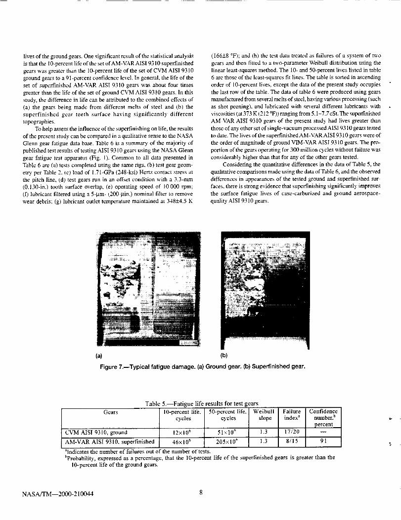
Hertzian line contact on any one tooth. Examples of fatigue damage are
shown in Fig. 7.
To provide a baseline for the present study, the data from Ref. 12
were selected as the most appropriate available. The tests of Ref. 12 were
conducted using the same rigs, lubricant, temperatures, loads, speeds,
Table 4.--Lubricant properties
[From refs. 12 and 16.]
Specification DOD-L-85734
Basestock Polyol-ester
Kinematic viscositT, cSt
311 K (100 °F) 27.6
372 K (210 °F) 5.18
Absolute viscosity, N-s/m 2
333 K (140 °F) 0.01703
355 K (180 °F) 0.00738
372 K (210 °F) 0.00494
Specific gravity
289 K (60 OF) 0.995
372 K (210 °F) 0.954
Pressure viscosib' coefficient (1/Pa)
313 K (104 °F) 11.4 x 10 -°
373 K (212 °F) 9.5 x 10 _
Total acid number (tan), MI_ Koh/g oil 0.40
Flash point, K (°F) 544 (520)
Pour point_ K (°F) 211 (-80)
and geometry specifications as the present study. The gear material of
Ref. 12 was CVM AISI 9310 steel, and the gear teeth surfaceg were
ground. There were 17 failures and 3 suspended tests for the CVM AISI
93 l0 ground gears, and there were 8 failures and 7 suspended tests for
the AM-VAR AISI 9310 superfinished gears. The test data were ana-
lyzed by considering the life of each pair of gears as a system. The data
were analyzed With the methods of Ref. 19.
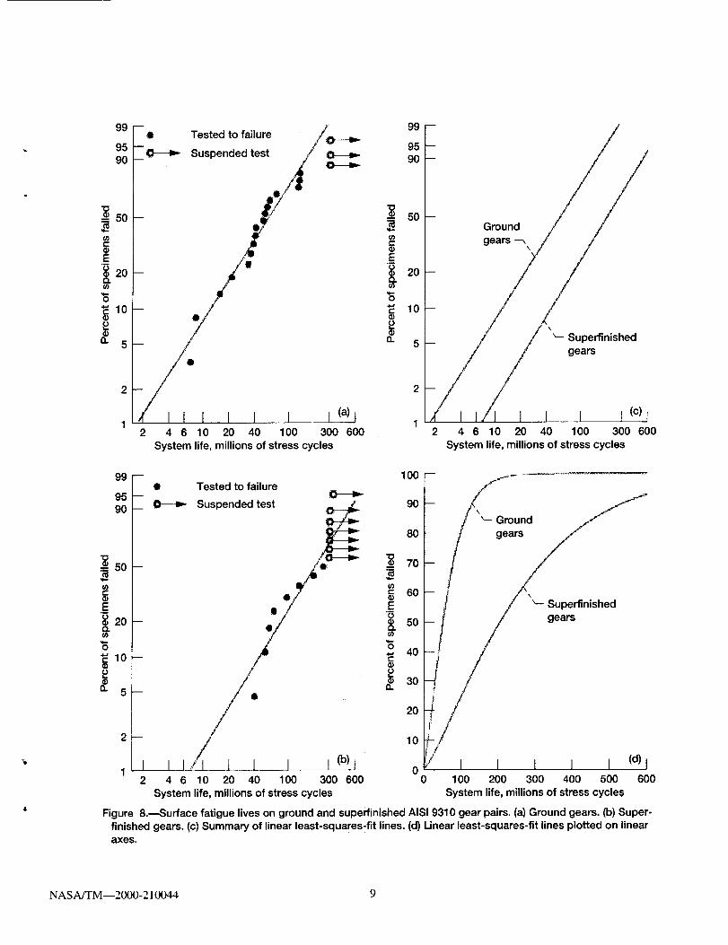
Surface fatigue test results for the CVM AISI 9310 ground gears
are shown in Fig. 8(a). The line shown on Fig. 8(a) is a least-squares
linear fit of the data to a two-parameter Weibull distribution. From the fit
line, the 10- and 50-percent lives of the sample population are 12×106
and 51 ×106 stress cycles. Surfaces that had been run but were not pitted
or spalled had a different appearance relative to the appearance before
testing. The grinding marks had become worn away and/or smeared, and
the running tracks on the gears were plainly evident (Fig. 7(a)).
Surface fatigue test results for the AM-VAR AIS193 l0 superfinished
gears are shown in Fig. 8(b). The line shown on Fig. 8(b) is a least-
squares linear fit of the data to a two-parameter Weibull distribution.
From the fit line, the 10- and 50-percent lives of the sample population
are 46× 106 and 205×106 stress cycles. Superfinished surfaces that had
been run and survived with no fatigue failure appeared almost like sur-
faces that had not been run. The running tracks on the gears were not
immediately evident but could be seen by close examination with a 10X
eyepiece. The wear and/or smearing that were seen on the ground gears
after testing were not observed on the tested superfinished gears.
The surface fatigue test results are summarized in Table 5 and
Figs. 8(c) and (d). Figure 8(c) shows the two least-squares linear fit lines
on one plot. The Weibull slopes are nearly equal, and therefore the gears
have similar relative failure distributions. Figure 8(d) shows the distribu-
tions of fatigue lives plotted using linear axes. This plot shows that for a
given reliability, the lives of the superfinished gears are greater than the
NASA/TM--2000-210044 7
livesofthegroundgears.Onesignificantresultofthestatisticalanalysisisthatthe10-percentlifeofthesetofAM-VARAIS19310superfinishedgearswasgreaterthanthe10-percentlifeofthesetofCVMAISI9310groundgearstoa91-percentconfidencelevel.Ingeneral,thelifeofthesetof superfinishedAM-VARAISI 9310 gears wa_s about four times
greater than the life of the set of ground CVM AISI 9310 gears. In this
study, the difference in life can be attributed to the combined effects of
(a) the gears being made from different melts of steel and (b) the
superfinished gear teeth surface having significantly different
topographies.
To help assess the influence of the superfinishing on life, the results
of the present study can be compared in a qualitative sense to the NASA
Glenn gear fatigue data base. Table 6 is a summary of the majority of
published test results of testing AISI 9310 gears using the NASA Glenn
gear fatigue test apparatus (Fig. 1). Common to all data presented in
Table 6 are (a) tests completed using the same rigs, (b) test gear geom-
etry per Table 2, (c) load of 1,71-GPa (248-ksi) Hertz contact stress at
the pitch line, (d) test gears run in an offset condition with a 3.3-mm
(0,130-in.) tooth surface overlap, (e) operating speed of l0 000 rpm;
(f) lubricant filtered using a 5-_tm- (200-Bin.) nominal filter to remove
wear debris; (g) lubricant outlet temperature maintained at 348+_4.5 K
(166+_8 °F); and (h) the test data treated as failures of a system of two
gears and then fitted to a two-parameter Weibull distribution using the
linear least-squares method. The i0- and 50-percent lives listed in table
6 are those of the least-squares fit lines. The table is sorted in ascending
order of 10-percent lives, except the data of the present study occupies
the last row of the table. The data of table 6 were produced using gears
manufactured from several melts of steel, having various processing (such
as shot peening), and lubricated with several different lubricants with
viscosities (at 373 K (212 °F)) ranging from 5.1-7.7 cSt. The superfmished
AM-VAR AISI 9310 gears of the present study had lives greater than
those of any other set of single-vacuum processed AIS19310 gears tested
to date. The lives of the superfinished AM-VAR AIS19310 gears were of
the order of magnitude of ground VIM-VAR AISI 9310 gears. The pro-
portion of the gears operating for 300 million cycles without failure was
considerably higher than that for any of the other gears tested.
Considering the quantitative differences in the data of Table 5, the
qualitative comparisons made using the data of Table 6, and the observed
differences in appearances of the tested ground and superfinished sur-
faces, there is strong evidence that superfinishing significantly improves
the surface fatigue lives of case-carburized and ground aerospace-
quality AISI 9310 gears.
(a) (b)
Figure 7.--Typical fatigue damage. (a)Ground gear. (b)Superfinished gear.
Table 5.--Fatigue life results for test gears
Gears 10-percent life. 50-percent life.
cycles cycles
CVM AISI 9310, ground 12x106 51x106
AM-VAR AISI 9310. superfinished 46x106 205x106
alndicates the number of failures out of the number of tests.
Weibull Failure Confidence
slope index a number, b
percent
1.3 17/20 m
1.3 8/15 91
bProbability, expressed as a percentage, that the 10-percent life of the superfinished gears is greater than the10-percent life of the ground gears.
NASA/'TM--2000-210044 8
99
9590
= 50
o3e-
E"_ 20O.O3
a. 5
99
9590
"_ 50
o3
E.m
20CLo3
0
a. 5
--• Tested to failure //F,_---b. v
__--_ Suspended test /
_ 0/_ '/_
2 4 6 10 20 40 100 300 600
System life, millions of stress cycles
99
9590
50
03e"
_EO 20O.01
O
Q.
10
: /
- e OaU: /_ /)/
t
__'i_,_ Superfinishedgears
I I I (c) t2 4 6 10 20 40 100 300 600
System life, millions of stress cycles
2--
1 I2
• Tested to failure
Suspended test y/ .__,
i I/t/// t 1 I I i) t
4 6 10 20 40 100 300 600
System life, millions of stress cycles
o3c-Q)
.E¢.)
r-
=u
o.
loo90
80
70
60
50
40
30
20
10
00
\
_-- Superfinishedgears
I I 1 I I (d) l100 200 300 400 500 600
System life, millions of stress cycles
Figure 8._Surface fatigue lives on ground and superfinished AISI 9310 gear pairs. (a) Ground gears. (b) Super-
finished gears. (c) Summary of linear least-squares'fit lines. (d) Linear least-squares-fit lines plotted on linearaxes,
NASA/TM--2000-210044 9

+++,_
E"+ ¸,i,.,,3
,- +eo
,-+_
,,& :>. ,._
.._ =-
+-.-P.
+..
t->.-,
B_
_=_+
t"q --
r'q _ I'-.| -- ¢".,I
2d u
0
t,-,
= _ _'_o.= ._> .>_ ,_
-- f-,|
• ..-, _ _
"_ ,'u _ ++"+r_.._-_ ©
_>>>>_ >>_
J _ t"q t"q t'_lt"_ t"-I _ t-q -- --
e- +,_
't".+ -- _ _ p,,.r++ 't''l t_+ _
>,> _,.+++> >._=_
_ x__ x xx x
X X X X X X X X X X,r,"h _ ,_s _ -- r'*"+ <+..r, _ _ t'_
r_l I'_1 t"',l <"+ _-+ +++"+
I-
:+.2_-_ :E K
- z z _ _ Z z
_ _ I_ _':_ r._, c._ _'_ _"_ _: 2_< >.
>+ > > +_ :;> _> ;;> ;> :> _
--_--_,__
0
?.
C_+...
X X "Xc..)
OC, "d"
i,',%
!.._ ,--- ,,+= <__ <._ It+
Z z _
>,> > __> > <
NASA/TM--2000-210044 10

CONCLUSIONS
A set of air-melt-vacuum arc-rerfielted (AM-VAR) AIS19310 steel
gears were ground and then provided with a near-mirror quality tooth
surface by superfinishing. The gear teeth surface qualities were evalu-
ated using metrology inspections, profilometry, and a mapping interfero-
metric microscope. The gears were tested for surface fatigue in the
NASA Glenn gear fatigue test apparatus at a load of 1.71 GPa (248 ksi)
and at an operating speed of 10 000 rpm until failure or until survival of
300 million stress cycles. The lubricant used was a polyol-ester base
stock meeting the specification DOD-L-85734. The failures were con-
sidered as failures of a two-gear system, and the data were fitted to a
two-parameter Weibull distribution. The results of the present study were
compared with the NASA Glenn gear fatigue data base. The following
results were obtained.
1. The superfinishing treatment removed about 2 to 3 /am (79 to
118 lain.) of material from the tooth surfaces.
2. The superfinishing treatment reduced the mean roughness average
(Ra) by a factor of about 5 and the mean 10-point parameter (Rz)
value by a factor of about 4.
3. The 10-percent life of the set of AM-VAR AISI 9310 superfinished
gears of the present study was greater than the 10-percent life of the
set of CVM AIS19310 ground gears of the baseline study to a 9 l-per-
cent confidence level.
4. In general, the life of the set of AM-VAR AISI 9310 superfinished
gears of the present study was about 4 times greater than the life of
the set of CVM AISI 9310 ground gears of the baseline study.
5. The set of AM-VAR AISI 9310 superfinished gears of the present
study had lives greater than those of any other set of single-vacuum
processed AIS19310 gears tested to date using the NASA Glenn gear
fatigue test apparatus.
6. The lives of the AM-VAR AIS19310 superfinished gears of the present
study were of the order of magnitude of VIM-VAR AIS19310 ground
gears when tested using the NASA Glenn gear fatigue test apparatus.
7. There is strong evidence that superfinishing significantly improves
the surface fatigue lives of case-carburized, ground, aerospace-qual-
ity AISI 9310 gears.
REFERENCES
I. Anderson, _\J., Parker, R.J., and Zaretsk2¢, E.V., 1962, "Effect of Nine
Lubricants on Rolling-Contact Fatigue Life," NASA TN D-1404.
2. Anderson, W.J., Sibley, L.B., and Zaretsky, E.V., 1963, "The Role of
Elastohydrodynamic Lubrication in Rolling-Contact Fatigue," Journal
of Basic Engineering. Vol. 85, pp. 439-450.
3. Townsend, D.P. and Shimski, J., 1991, "Evaluation of Advanced Lubri-
cants for Aircraft Applications Using Gear Surface Fatigue Tests," NASA
TM-104336.
4. Tanaka, S., lshibashi, A., and Ezoe, S., 1984, "Appreciable Increases in
Surface Durability of Gear Pairs With Mirror-Like Finish," ASME
Publication 84-DET-223, ASME, New York, NY..
5. Ishibashi, A., Ezoe, S., and Tanaka, S., 1984, "Mirror Finishing of
Tooth Surfaces Using a Trial Gear Grinder With Cubic-Bom-NitrideWheel," ASME Publication 84-DET-153, ASME, New York, NY.
6. Nakatsuji. T., Mort, A., and Shimotsuma, Y., 1995, "Pitting Durability of
Electrolytically Polished Medium Carbon Steel Gears," Tribology Trans-
actions, Vol. 38, No. 2, pp. 223-232.
7. Nakatsuji, T. and Moil, A., 1999, "Pitting Durability of Electrolytically
Polished Medium Carbon Steel Gears--Succeeding Report," Tribology
Transactions, Vol. 42, No. 2. pp. 393-400.
8. Hoyashita, S., Hashimoto, M., and Seto, K., 1998, "Basic Studies on
Fatigue Strength of Case-Hardened Gear Steel--Effects of Shot Peen-
ing and/or Barrelling Processes," AGMA Publication 98FTM3.
9. Hashimoto, M., Hoyashita, S., and Iwata, J., 1998, "Studies on Improve-
ment of Surface Durability of Case-Carburized Steel Gear--Effects of
Surface Finish Processes upon Oil Film Formation," AGMA Publica-tion 98FTM9.
10. Patching, M.J., Kweh, C.C., Evans, H.E, and Snidle, R.W., 1995, "Con-
ditions for Scuffing Failure of Ground and Superfinished Steel Disks at
High Sliding Speeds Using a Gas Turbine Engine Oil,"
Tribology Transactions, Vol. 117, No. 3. pp. 482-489
11. Townsend, D.E, Chevalier, J.L., and Zaretsky, E.V., 1973, "Pitting
Fatigue Characteristics of AISI M-50 and Super Nitralloy Spur Gears,"NASA TN D-7261.
12. Townsend, D.E, and Shimski, J., 1994, "Evaluation of the EHL Film
Thickness and Extreme Pressure Additives on Gear Surface Fatigue Life,"
NASA TM- 106663.
13. Zaretsky, E.V.,1997, TJ4bologyfor Aerospace Applications, STLE SP-37.
14. Henry, Z.S., 1995, "Bell Helicopter Advanced Rotorcraft Transmission
(ART) Program," NASA CR-195479.
15. Snidle, R.V_\, Evans, H.E, and Alanou, M.E, 1997, "The Effect of
Superfinishing on Gear Tooth Profile,'" AD-A327916, Defense Techni-
cal Information Center, Ft. Belvoir, VA.
16. Present, D.L.; Newman, F.M.; Tyler, J.C.; and Cuellar, J.E, 1983,
"Advanced Chenfical Characterization and Physical Properties of Eleven
Lubricants," NASA CR-168187.
17. Anderson, N.E.; Lowenthal, S.H.; and Black, J.D., 1984, "An Analytical
Method to Predict Efficiency of Aircraft Gearboxes," NASA TM-83716
(AIAA Paper 84-1500).
18. Anderson, N.E. and Lowenthal, S.H., 1980, "Spur-Gear-System at Part
and Full Load," NASA TP-1622.
19. Johnson, L.G., 1964, The Statistical Treannent of Fatigue Experiments,
Elsevier Publishing Co., New York, NY.
20. Townsend, D.P. and Zaretsky, E.V., 1985, "Effect of Five Lubricants on
Life of AIS19310 Spur Gears," NASA TP-2419.21. Scibbe, H.W., Townsend, D.P., and Aron, P.R., 1984, "Effect of
Lubricant Extreme-Pressure Additives on Surface Fatigue Life of AISI
9310 Spur Gears," NASA TP-2408. _,
22. Coy, J.J., Townsend, D.E, and Zaretsky, E.V., 1975, "Analysis of
Dynamic Capacity of Low-Contact-Ratio Spur Gears Using Lundberg-
Palmgren Theory," NASA TN D-8029.
23. Townsend, D.E, 1982, "Effect of Shot Peening on Surface Fatigue Life
of Carburized and Hardened AISI 9310 Spur Gears," NASA TP-2047.
24. Townsend, D.E, Turza, A., and Chaplin. M., 1995, "The Surface Fatigue
Life of Contour Induction Hardened AISI 1552 Gears," NASA
TM-107017.
25. Townsend, D.E and Zaretsky, E.V., 1980, "Comparisons of Modified
Vasco X-2 and AISI 9310 Gear Steels," NASA TP-1731.
26. Townsend, D.E, 1992, "Improvements in Surface Fatigue Life of
Hardened Gears by High-Intensity Shot Peening," NASATM-105678.
27. Townsend, D.P and Bamberger, E.N., 1989, "Surface Fatigue Life of
Carburized and Hardened M50NiL and AIS19310 Spur Gears and Roll-
ing-Contact Test Bars," NASA TM-101979.
NASA/TM--2000-210044 11
REPORT DOCUMENTATION PAGE FormApprovedOMB No. 0704-0188
Public reporting burden for this collection of information is estimated to average 1 hour per response, including the time for reviewing instructions, searching existing data sources,
gathering and maintaining the data needed, and completing and reviewing the collection of information. Send comments regarding this burden estimate or any other aspect of this
collection of information, including suggestions for reducing this burden, to Washington Headquarters Services, Directorate for Information Operations and Reports, 1215 Jefferson
Davis Highway, Suite 1204, Arlington, VA 22202-4302, and to the Office of Management and Budget, Paperwork Reduction Project (0704-0188), Washington, DC 20503.
1. AGENCY USE ONLY (Leave blank) 2. REPORT DATE
April 2000
4. TITLE AND SUBTITLE
Surface Fatigue Lives of Case-Carburized Gears With
an Improved Surface Finish
6. AUTHOR(S)
T.L. Krantz, M.R Alanou, H.R Evans, and R.W. Snidle
7. PERFORMING ORGANIZATION NAME(S) AND ADDRESS(ES)
NASA Glenn Research Center
Cleveland, Ohio 44135-319 land
U.S. Army Research Laborato_'Cleveland, Ohio 44135-319l
9. SPONSORING/MONFFORING AGENCY NAME(S) AND ADDRESS(ES)
National Aeronautics and Space Administration
Washington, DC 20546_)001and
U.S. Arm 3,Research Laboratory
Adelphi, Maryland 20783-1145
3. REPORT TYPE AND DATES COVERED
Technical Memorandum
5. FUNDING NUMBERS
WU-581-30-13-00
1LI62211A47A
8. PERFORMING ORGANIZATIONREPORT NUMBER
E-12087
lO, SPONSORING/MONITORINGAGENCY REPORT NUMBER
NASA TM--2000-210044
ARL-TR-2170
DETC2000/PTG-14373
11. SUPPLEMENTARY NOTES
Prepared for the 2000 Design Engineering Technical Conferences and Computers and Information in Engineering Conference
sponsored by the American Society of Mechanical Engineers, Baltimore, Maryland, September 10-13, 2000. T.L. Krantz, U.S.
Arm 3, Research Laboratory, Glenn Research Center; M.P. Alanou, H.P. Evans, and R.W. Snidle, Cardiff University, P.O. Box 685,
Cardiff CF24 3TA, Wales, United Kingdom. Responsible person, T.L. Krantz, organization code 5950, (216) 433-3580.
12a. DISTRIBUTION/AVAILABILITY STATEMENT
Unclassified - Unlinfited
Subject Categories: 07 and 37 Distribution: Nonstandard
This publication is available from the NASA Center for AeroSpace Information. (301) 621-0390.
12b. DISTRIBUTION CODE
13. ABSTRACT (Maximum 200 words)
Previous research provides qualitative evidence that an improved surface finish can increase the surface fatigue fives of
gears. To quantify the influence of surface roughness on life, a set of AISI 9310 steel gears was provided with a near-
mirror finish by superfinishing. The effects of the superfinishing on the quality of the gear tooth surfaces were deter-
mined using data from metrology, profilometry, and interferometric microscope inspections. The superfinishing reduced
the roughness average by about a factor of 5. The superfinished gears were subjected to surface fatigue testing at
1.71-GPa (248-ksi) Hertz contact stress, and the data were compared with the NASA Glenn gear fatigue data base. The
lives of gears with superfinished teeth were about four times greater compared with the fives of gears with ground teeth
but with otherwise similar quality.
14. SUBJECT TERMS
Gears; Fatigue tests; Fatigue life; Pitting; Weibull density functions; Surface roughness
17. SECURITY CLASSIFICATIONOF REPORT
Unclassified
NSN 7540-01-280-5500
18. SECURITY CLASSIFICATIONOF THIS PAGE
Unclassified
19. SECURITY CLASSIFICATIONOF ABSTRACT
Unclassified
15. NUMBER OF PAGES
1716. PRICE CODE
A0320. LIMITATION OF ABSTRACT
Standard Form 298 (Rev. 2-89)Prescribed by ANSI Std. Z39-18
298-102