research in visible light communication systems with openvlc1
TRANSCRIPT
Research in Visible Light Communication Systemswith OpenVLC1.3
Ander GalisteoIMDEA Networks Institute &
Universidad Carlos III de MadridMadrid, Spain
Diego JuaraIMDEA Networks Institute
Madrid, [email protected]
Domenico GiustinianoIMDEA Networks Institute
Madrid, [email protected]
Abstract—In this paper, we present the design and implemen-tation of our latest OpenVLC1.3 platform to perform research inVisible Light Communication Systems. We retain the advantagesof the previous versions such as TCP/IP layers support, soft-ware programmability and low-cost front-end. We re-design thetransceiver to support higher modulation rates and sensitivity.This allows us to reach a throughput of 400 kb/s (a factor of 4with respect to the previous version) and increase the distanceby a factor of 3.5. We further improve the software robustnessof the system and reduce the form factor at similar hardwarecost.
I. INTRODUCTION
Visible Light Communication is gaining significant interestas a medium to connect to the Internet [1]–[3]. In the last fewyears, a range of applications have been developed with low-end Visible Light Communication (VLC) platforms: humansensing [4], communication with toys [5], mobile interac-tion [6], indoor localization [7], [8] and passive VLC [9], [10].Industry interest is also resulting in the establishment of theIEEE 802.11bb task group, where the objective is to amend theMedium Access Control (MAC) and Physical Layer (PHY) ofIEEE 802.11 with Light Communications [11].
To solve the lack of an open-source and flexible platformfor low-end VLC research, we introduced OpenVLC at theVLCS’14 workshop [12], that allowed for quick and flex-ible testing of new VLC protocols and applications. Morerecently, we introduced OpenVLC1.2 [13] with the attempt ofincreasing the data rate. However, the board was still workingonly at relative short range and was largely affected by lightinterference.
In this paper, we introduce the latest version of our platform,OpenVLC1.3, that increases the data rate and the communica-tion range without adding any hardware cost to the platform.Our contributions are as follows:• We make a design that occupies a smaller physical space,
improve the hardware of OpenVLC1.3 and add high-passand low-pass filters to minimize the effect of noise inthe system, including the Direct Current (DC) from other
The project that gave rise to these results received the support of afellowship from ”la Caixa” Foundation (ID 100010434). The fellowship codeis LCF/BQ/ES16/11570019.
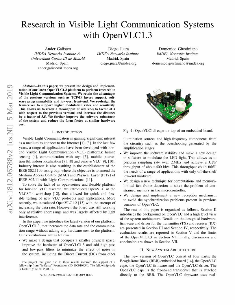
Fig. 1: OpenVLC1.3 cape on top of an embedded board.
illumination sources and high-frequency components fromthe circuitry such as the overshooting generated by theamplification stages.
• We improve the software stability and make a new designin software to modulate the LED light. This allows us toperform sampling rate over 2 MHz and achieve a UDPthroughput of about 400 kb/s. This throughput could fulfillthe needs of a range of applications with only off-the-shelflow-end hardware.
• We design a new technique for computation- and memory-limited fast frame detection to solve the problem of con-strained memory in the microcontroller.
• We design and implement a new reception mechanismto avoid the synchronization problems present in previousversions of OpenVLC.The rest of this paper is organized as follows. Section II
introduces the background on OpenVLC and a high level viewof the system architecture. Details on the design of hardware,firmware and driver for the transmitter (TX) and receiver (RX)are presented in Section III and Section IV, respectively. Theevaluation results are reported in Section V and the limitsof the OpenVLC1.3 in Section VI. Finally, discussions andconclusion are drawn in Section VII.
II. NEW SYSTEM ARCHITECTURE
The new version of OpenVLC consist of four parts: theBeagleBone Black (BBB) embedded board [14], the OpenVLCcape, the OpenVLC firmware and the OpenVLC driver. TheOpenVLC cape is the front-end transceiver that is attacheddirectly to the BBB. The OpenVLC firmware uses real-978-1-5386-4980-0/19/$31.00 2019 IEEE
arX
iv:1
812.
0678
8v2
[cs
.NI]
5 M
ar 2
019

TABLE I: Comparison between OpenVLC versions.
TX HW TX SW RX HW RX SW Data rateOpenVLC1.0 High Power LED Kernel software Basic components Running in Kernel 18kb/s
OpenVLC1.2 Support for higher powerLED and faster modulation
Firmware with user spaceconnection
Faster PD andexternal amplifier
New frame detection andfaster reception in firmware 100kb/s
OpenVLC1.3 More powerful LEDand external power
Faster firmware anddirect connection to Kernel
Filters to remove interferencesand reduced cape size
New frame andsymbol detection 400kb/s
Application layer
Transport layer
Network layer
VLC MAC
Non-time sensitive VLC PHY
TCA
TIATime sensitiveVLC PHY
Kernel Space
User Space
HardwareSoftware
OpenVLC Driver
PRU
LED
PD
Fig. 2: The diagram of OpenVLC1.3.
time processing in the BBB’s Processing Real-time Units(PRUs), that work as microprocessors. The OpenVLC driveris a module in the Linux kernel. Both the firmware and thekernel module implement the VLC MAC and PHY layersand implement primitives such as sampling, symbol detection,coding/decoding and Internet protocol interoperability. Also,OpenVLC1.3 retains the best characteristics of previous ver-sions, being flexible and open-source and communicating witha low-cost front-end.
With respect to its predecessor, the architecture of Open-VLC1.3 has been re-designed in order to increase the networkperformance. The new hardware (HW), called OpenVLC1.3cape, is shown in Fig. 1. The OpenVLC1.3 cape has beenmodified, reducing its surface by more than 50%. This alsoallows to use the remaining pins to connect sensors, forinstance for Internet of Things applications.
The system architecture of OpenVLC1.3 is shown in Fig. 2.The hardware runs on external power to allow higher powerconsumptions and harnesses the new LED and Photodiode(PD), together with ancillary circuits, to transmit and receivevisible light signals, respectively. The software is responsiblefor modulating the LED light in order to transmit and samplethe incoming signals to receive, both implemented in theOpenVLC1.3 firmware. The software also implements theMAC layer and part of PHY layer in the OpenVLC1.3 driver.
There are three main differences in the design comparingOpenVLC1.3 to its predecessors:• A new design of the OpenVLC cape (hardware).• A new system architecture (both in software and hardware).• A firmware implemented in the PRUs for data transmission
as well as frame and symbol detection (software).To boost the date rate in OpenVLC1.3, we exploit the
PRUs of the BBB. Time-sensitive operations are implementedin the 2 PRUs that control the General Purpose Input-Output (GPIO) to modulate LED light and perform samplingof incoming signals. This separation was also proposed inOpenVLC1.2, but resulted in overall lower performance and
required some module in user space. Communication betweenthe driver and the firmware is now performed using a sharedmemory. A new technique for computation- and memory-limited frame detection also resides in the firmware (the detailsare presented in Sec. IV). The OpenVLC driver implementsthe MAC protocol and non-time sensitive PHY operations.This maintains the advantages of software-based flexibility andprogrammability while increasing its performance.
OpenVLC1.3 is already available to the research commu-nity1. A summary of the improvements of each version canbe found in Tab. I.
A. Data exchange
The data stream is received in the driver from upper layers.The VLC frame is prepared and then the symbol stream is sentto the shared memory from where it is read by the firmware inthe PRU, as seen in Fig. 2. The PRU then controls the GPIOsto modulate the LED light for data transmission.
At the receiver, light signals are detected by the PD andsampled by the firmware in the PRUs. Once a valid preambleand Start-Frame-Delimiter (SFD) are detected, received datais sent to the shared memory, and then received and processedby the OpenVLC driver. Finally, the received data is sent tothe network layer, where it is handled using the TPC/IP Linuxkernel.
B. Firmware
The firmware of OpenVLC runs in the PRUs of the BBB,which operates at 200 MHz, meaning that each instructiontakes 5 ns. Each PRU has its own memory and a shared onebetween the two. The size of each memory of the PRUs is 8KBand the shared memory is 12KB. The reason behind adoptingthe PRUs in OpenVLC is to increase the data rate and handle ahigher sampling frequency of the Analog-to-Digital Converter(ADC). Nevertheless, this effort also requires a tight timingprecision in both the modulation and sampling processes. Forthis reason, assembly is used to program the PRU. In this way,the code of the PRU has been designed to know the exactnumber of instructions executed and, subsequently, the timerequired to execute them. In addition, the memory space inthe PRU is very limited and this requires careful optimizationof all instructions. Finally, there is no enough memory toimplement queues, and as such, the communication betweenthe PRU and upper layers must be handled carefully.
C. Kernel Driver
The main objective of OpenVLC is to have a flexible,low-cost and reconfigurable system for communication using
1www.openvlc.org

TABLE II: Frame format and sizes (in bytes).
Preamble SFD Frame Length Dst. Address Src. address Payload Reed-Solomon3 1 2 2 2 0-MAX 16
visible light. In order to do so, OpenVLC1.3 has been designedto be as versatile and easy to use as possible. For this reason,we have taken two design decisions:• OpenVLC is mostly code-based and the use of VLC hard-
ware is as small as possible. This makes easy to modifythe behavior of the platform just by modifying the softwarecode, such as introducing new MAC protocols.
• OpenVLC should be easy to use and adaptable to mostuse case scenarios. Taking this into account, OpenVLC’sinterface has been designed as a Linux kernel module.The OpenVLC kernel module allows us to create a network
interface. This means that any user will see the OpenVLCmodule as if it is just another network device such as Wi-Fi or Ethernet and any application that we would like to runwould be connected through the VLC network interface. Asthe kernel runs in the processor of the BBB, its processingpower is much higher than the one of the PRU microcontroller.For this reason, the most computationally demanding tasks areleft in the kernel.
III. TRANSMITTER
In this section we present all the different parts that allowOpenVLC to perform a VLC transmission.
A. Kernel module for transmissionWhen a user space application transmits data, first the packet
is received from the IP layer of the kernel. After unwrappingthe frame, the driver prepares the header for the VLC MAClayer. The frame structure is presented in Table II. Each framestarts with a frame header that contains the following fields:preamble, SFD, frame length, destination address and sourceaddress. Each field in the MAC header (starting from the framelength) can be freely modified, for instance to adapt it to theIEEE 802.15.7-2011 standard for VLC [15] and upcoming802.11bb standard for integration with Wi-Fi [11].
The preamble consists of 24 alternating HIGH and LOWsymbols. After that, the SFD is appended to avoid falsepositives. The next field denotes the length of frame in bytes,followed by the destination and source addresses.
We use Reed-Solomon code to correct errors in the datafield during the transmission. The bits for Reed-Solomon areappended to the frame. We use Reed-Solomon (216,200) errorcorrection code in our default configuration. Subsequently, weuse Manchester line encoding, which encodes one bit into twosymbols with On-Off-Keying (OOK) modulation (a symbol iseither a HIGH or a LOW) and it ensures that the averagesignal power remains constant. In particular, Manchester linecoding converts a 1 bit into a LOW-HIGH symbol pair and a0 into a HIGH-LOW. This is done to avoid flickering. BothReed-Solomon code and Manchester encoding are also usedin the 802.15.7-2011 standard [15]. Finally, the driver placesthe VLC frame in a shared memory, so that the OpenVLCfirmware in the PRU can access it.
PRU 0
OpenVLCdriver
# 0 1 2 3 … n
Size: 8KB
(a) Memory sharingbetween the Open-VLC driver and thePRU0 at the trans-mitter.
PRU 0 PRU 1
OpenVLC driver
# 0 1 2 3 … nVLC Channel
# 0 1 2 3 … n
Size: 8KB
Size: 12KB
(b) Memory sharing between the PRUs andbetween PRU1 and the OpenVLC driver at thereceiver.
Fig. 3: Memory interface of OpenVLC1.3 (‘#’ stores thephysical address of the latest updated data).
B. Shared memory
In Fig. 3(a) we show how the shared memory is used inOpenVLC. The kernel driver transmit data to the PRU using ashared memory. The first 32-bits (referred as the first ‘register’in the rest of this paper) of the shared memory are the onlyspace where the PRU can write data. This register is used toexchange status flags between the kernel and the PRU.
The communication works as follows: the PRU constantlyreads the value of the first register. If it is zero, it reads it againin a loop, waiting for its value to change. If the kernel receivesdata from upper layers, it will modulate it and put it the sharedmemory. When it finishes, it writes in the first memory addressthe number of registers that the PRU should read. The kernelwill not be able to write into the shared memory again until thePRU finishes the transmission. The PRU will then transmit thedata and once it finishes, it changes the flag in the first memoryregister to zero so that the kernel knows that the memory isavailable again.
C. Firmware for signal transmission
For the transmission, the PRU is used for the sole purposeof emitting the visible light signal according to the pattern ofHIGH and LOW symbols stored in the shared memory. TwoPRUs are available in the BBB, and only one PRU is used fortransmitting the signal. We implement a counter to track thetime between symbols. When it reaches zero, a new symbolis transmitted. In order to transmit each symbol, a HIGH orLOW signal is sent through one of the pins of the BBB. Inthe current implementation, HIGH corresponds to emitting thevisible light signal and LOW to not emitting any signal.
D. Hardware improvement
The main purpose of the TX circuit is to take the signalgiven by the BBB and amplify it to turn the LED on/off.As mentioned above, the HW is controlled using the firmwareimplemented in the BBB’s PRUs. The HW used for the Open-VLC transmitter can be seen in Tab. III. We have improved the

TABLE III: Main components of OpenVLC1.3.
Component NameADC ADS7883
OP-AMP LTC6269MOSFET FQPF30N06L
LED XHP35A-01-0000-0D0HC40E7CTLens TINA FA10645PD SFH206K
DC-DC LM2585SX-ADJ
TX circuit compared with previous versions mainly to supporta higher transmission rate and a larger communication range.• Increase the transmission rate: we use a PRU at the TX
to modulate the LED light at higher speeds. Moreover, weuse a MOSFET gate driver transistor to control the currentflowing to the LED and support a faster switch.
• To expand the communication range: a LED that maximizesthe power supported by the transmission circuit, workingat 2.8 W with a luminous flux of 400 lm. A lens hasbeen attached on top of the LED to better concentrate theoptical power and thus, reach further distance. A heat-sinkis attached to better dissipate the heat generated by the high-power LED.
IV. RECEIVER
In this section we explain the design and behavior of the RX.
A. Hardware for reception
In the previous versions of OpenVLC, the bottleneck forthe throughput was the RX’s sampling rate. In OpenVLC1.3,this is solved partly by introducing a new faster photodiode(PD). This PD does not have its own amplifying circuit. Thus,we add an external amplifier to the RX. The PD’s position inthe cape is also adjusted for a better detection of visible light.The most important components are shown in Tab. III.
The bottleneck of the system for the transmission distanceon the reception circuit was the high sensitivity to noise onthe receiver circuit. For this reason, a reception chain has beenadded between the PD and the ADC. In previous versions therewas only an amplification stage between the PD and the ADC.In this version, as seen in Fig. 4, the first amplification stageis a low-noise Trans-Impedance-Amplifier (TIA) that convertsthe current of the PD into voltage.
Subsequently, a high-pass filter is used in order to removethe low frequency components (specially the DC componentfrom other illumination sources). The cut-off frequency of thisfilter is 10 KHz. This filter allows us to remove the DC lightcomponent and other sources of interference. Although non-visible for the human eye, a light flickering at this frequencywould distort the VLC signals. After this, a DC component of2.5 V is added to the signal so that the signal is centered athalf the span of the ADC. Then, the second amplification stageprepares the signal for the dynamic range of the ADC. Finally,before the ADC, a low-pass filter with cut-off frequencyof 1.1 MHz removes the higher frequency noise componentsmainly due to overshooting of the amplifiers.
Photodiode
1st Amplification stage 2nd Amplification stage
High pass filter Low pass filter
Fig. 4: Reception chain.
B. Firmware for signal reception
The configuration of the RX is more complex than of theTX. It requires two PRUs. One for handling the HW in a veryprecise manner and another for processing the received signal.
One of them, PRU0, performs signal sampling from theADC and obtains the Received Signal Strength (RSS) andsends it to the other PRU, PRU1, that handles signal detectionand the process of converting the raw signal into bits. PRU0
reads the RSSs from the ADC at a frequency higher than twicethe symbol rate.
Then, the raw value from the channel is shared with PRU1.PRU1 interprets the RSSs into symbols for frame detection.PRU1 continuously checks if a new RSS has been read byPRU0. If yes, PRU1 processes it immediately.
1) The bit slip problem: One of the most sensitive stages ina communication system is the correct reception of transmittedsymbols. One of the main problems with low-cost systemsis that TX and RX get easily desynchronized over time.Their clocks are not exactly the same and the frequenciesat which they run are slightly different. This could makethe system sample a symbol twice or miss a symbol. Thisproblem is known as “bit slip” [16]. In the older OpenVLC1.2,the TX and RX frequency were adjusted to the instructionlevel. This meant that there are exactly the same number ofinstructions between two symbols transmission and betweentwo symbols reading. However, the clocks in the TX and RXalways run at slightly differently frequency, and thus, part ofthe synchronization problems was still present.
In order to solve this problem, we need to make sure that:• All the symbols are sampled at least twice.• The system should detect if a symbol has been sampled
more than twice.OpenVLC1.3 over-samples the signal to assure that all the
symbols are sampled at least twice. The higher the oversam-pling rate, the more information the system is going to have todetect the symbol correctly. Nevertheless, a high oversamplingrate requires a fast processing. In our case, in order to fulfillthe requirements mentioned above, the sampling frequencyfsampling should be:
2fsymbol < fsampling < 3fsymbol (1)
With this configuration, OpenVLC1.3 makes sure that wealways receive at least 2 sample per symbol and a maximumof 3. It is not possible to receive 4 samples per symbol,which is necessary to assure the second condition. In theimplementation, we modulate at 1 MHz and sample at thereceiver at a rate of 2.1 MHz.
The symbol detection in OpenVLC1.2 was just a threshold-ing algorithm with one sample per symbol with the consequent

(a) 1 sample per symbol (sym-bol lost).
(b) 2 sample per symbol (nosymbol lost).
Fig. 5: Bit sleep problem. The red circles represent the idealsampling time. The grey stars represent the real sampling timegiven by the drift.
bit sleep problem. In OpenVLC1.3, we avoid this by usinga pseudo-edge detection algorithm. Manchester modulationconverts a 1 bit into a LOW-HIGH symbol pair and a 0into a HIGH-LOW. This means that the maximum numberof symbols with the same value is 2. There cannot be morethan 2 consecutive HIGHs or LOWs. With two samples persymbol, the system makes sure to read at least each symboltwice, at it can be seen in Fig. 5.
OpenVLC1.3 can count the number of samples with thesame value. If the number of samples is 2 or 3, only 1 symbolhas been received. If the number of samples is 4 or 5, 2symbols have been received. This method can be thought asa very simple and rudimentary edge detection system, as itlooks for changes in the signal to see when a new symbol (orpair of symbols with the same value, depending on how longago was the last change in the signal) has been received.
2) Frame detection: The system assumes that a new frameis being detected when the last samples received correspondto the preamble + SFD. The frame detection technique is theone used in OpenVLC1.2 [13] as it showed to be both low-complexity in processing (required by our application) andvery effective. This technique works as follows: First, the RSSvalues read are compared with their previous values. Becauseat the beginning of a frame in the preamble (0xAAAAAA)every HIGH is between two LOWs and every LOWs betweentwo HIGHs, every symbol is different from the previous one.If the value of the last 24 bits received is not the same as thepreamble, the system continues to collect samples. If it does,continues receiving data.
Once the preamble is detected it continues receiving the restof the frame. Once received and demodulated, the data is sentto the OpenVLC driver for further processing.
3) Communication between PRUs: The signal receptionstarts with the PRU0 reading values from the ADC and puttingthem in a memory shared by both PRUs. This memory is usedas a circular memory. When it reaches the end, it continuesfilling the beginning of the shared memory. In the first register,the address of the latest memory where data has been writtenis stored as illustrated in Fig. 3(b). In this way, PRU1 is able tokeep track of the RSS obtained by PRU0 in real time. Then, thePRU1 processes the samples taking two symbols at a time, todetermine if the encoded Manchester bit is a 1 or a 0. If theycontain valid data, it is decoded and shared with the kernelusing the same process as for the transmitter.
C. Kernel for reception
The frame is received by the kernel after being convertedfrom symbols to bits in the PRU. The Reed-Solomon code ischecked with three possible outputs:• The Reed-Solomon reports no errors, so the packet is
forwarded.• The Reed-Solomon shows some errors that is able to correct,
so corrects them and forwards the packet.• The Reed-Solomon code shows that there are too many
errors, so discards the packet.If the packet is forwarded, the kernel encapsulates the packet
so that upper layers can manage it.Both in the transmission and in the reception of packets,
OpenVLC considers that, although more powerful, the kernelcannot run in real time. For this reason, two driver queuesare implemented, one for transmission and one for reception.Every incoming packet that arrives to the kernel is queuedand transmitted to the PRU or to upper layers as soon asthe resources are available. In this way, we minimize thelikelihood of losing a frame because the CPU is occupied.
V. EVALUATION
In this section we evaluate the performance of OpenVLC1.3.
A. Reception chain
In order to understand the behavior of the reception chainwe have measured the raw signal with an oscilloscope. As itcan be seen in Fig. 6, the signal is noisy and small after thefirst amplifier. Then, the signal is filtered and centered aroundthe center of the ADC’s span. Finally, the signal is amplifiedand cleaned, to improve the reception.
B. Throughput vs. payload
1) Setup: We use two OpenVLC1.3 nodes, one as TXand the other as a RX. Since OpenVLC1.3 provides a newnetwork interface that can be easily accessed by upper layerapplications, we use the tool iperf to evaluate the UDPperformance of OpenVLC1.3.
2) Results: The first test performed is to see how the systemworks depending on its payload. In previous versions ofOpenVLC, the payload had a huge impact in the system. If thepayload was too short, the overhead due to the physical layerheaders was too big, decreasing the throughput. Nevertheless,if the payload was too big, the reception was desynchronizedand the frame lost. As we modify the symbol detectiontechnique, now no frames are lost due to the size of thepayload. For this reason, the bigger the payload, the better.All the following tests are done with payloads of 800 bytes.
Throughput vs. distance. This test contains the two mostimportant parameters regarding VLC. The first one is thedistance at which the VLC communication takes place. Thesecond one is the maximum throughput achievable by thesystem. OpenVLC has been tested over distance under 3different scenarios. In the first one, the system has beendeployed in a realistic scenario with no artificial lights on (hereOpenVLC is seen as the primary illumination source), but with

0 1 2 3 4 5Time (s) 10-6
0.2
0.4
0.6
0.8
1
Vol
tage
(V
)
0 1 2 3 4 5Time (s) 10-6
2.3
2.4
2.5
2.6
2.7
2.8
Vol
tage
(V
)
0 1 2 3 4 5Time (s) 10-6
1
2
3
4
Vol
tage
(V
)
Fig. 6: Received signal after the first amplifier (left), after the high-pass filter (center) and at the entrance of the ADC (right).
0 2000 4000 6000 8000Distance (mm)
0
100
200
300
400
Thr
ough
put (
kb/s
) W. openW. closedInterference
Fig. 7: UDP throughput as a function of the distance.
the windows open during the day (“W. open”). In the secondone, OpenVLC is tested without any external light interferenceand the window shutter closed (“W. closed”). In the last one,we open the windows, and we add an artificial fluorescent lightsource with frequency components that enter in the frequencyband of the OpenVLC receiver (“Interference”).
As it can be seen in Fig. 7, the maximum throughput thatOpenVLC achieves is 400 kb/s. Until 3.5 meters, the differencebetween being in a completely dark environment (“W. closed”)and with external light (“W. open”) is negligible, which did nothappen in previous versions. This is due to the filters addedin the reception chain. Then, at 3.5 meters the intensity ofthe external light level becomes similar to transmitted light,making it more difficult for the ADC to differentiate betweenHIGH and LOW symbols, so the throughput starts to drop.When the windows are closed, the communication is possibleat longer range, reaching 6 meters.
In summary, the maximum achievable distance is more thanthree times better than the previous version and 6 times betterthan the original one. Also, the throughput is 4 times betterthan the previous version and more than 22 times better thanthe first version [12] [13].
VI. LIMITATIONS OF THE SYSTEM
The OpenVLC1.3 platform has several limitations, as anyreal system. The first one is that the throughput can notbe improved without major changes in both software andhardware. Changing the ADC would increase the cost ofthe board and the processing power required to perform thereception. Also, although technically possible to use OpenVLCas a transceiver, in the current version, the throughput ismaximized using one board as transmitter and one as receiver.
In addition, the communication is UDP, as there is no returnVLC link in the system. This design decision has been takenafter realizing that:
• The processing power of the BBB’s PRUs is limited, andhaving a bidirectional system requires at least twice asprocessing power as an one-way link.
• The current trend in networking is that VLC will operate inhybrid systems, where the downlink is VLC and the uplinkis RF. By using the USB interface in the BBB, users may,for instance, use Wi-Fi to send uplink data as well as ACKsfor downlink VLC.
VII. CONCLUSION
In this paper, we have presented our latest OpenVLC versionand we have evaluated its performance improvements. Tothe best of our knowledge, OpenVLC1.3 is the first low-cost research platform that achieves a UDP throughput of400 kb/s using only low-end off-the-shelf hardware. Apartfrom being used for research and teaching as its predecessors,OpenVLC1.3 can enable real-world applications.
REFERENCES
[1] “pureLiFi,” https://purelifi.com/, 2018.[2] J. Zhang, X. Zhang, and G. Wu, “Dancing with light: Predictive in-frame
rate selection,” in Proc. IEEE INFOCOM, 2015, pp. 1–9.[3] C. B. Liu, B. Sadeghi, and E. W. Knightly, “Enabling vehicular visible
light communication (V2LC) networks,” in Proc. VANET, 2011.[4] T. Li, C. An, Z. Tian, A. T. Campbell, and X. Zhou, “Human sensing
using visible light communication,” in ACM MobiCom, 2015.[5] N. O. Tippenhauer, D. Giustiniano, and S. Mangold, “Toys communi-
cating with leds: Enabling toy cars interaction,” in IEEE CCNC, 2012.[6] C. Zhang, J. Tabor, J. Zhang, and X. Zhang, “Extending mobile
interaction through near-field visible light sensing,” in Proc. MobiCom.ACM, 2015, pp. 345–357.
[7] Y.-S. Kuo, P. Pannuto, K.-J. Hsiao, and P. Dutta, “Luxapose: Indoorpositioning with mobile phones and visible light,” in Proc. MobiCom.ACM, 2014, pp. 447–458.
[8] C. Zhang and X. Zhang, “Litell: robust indoor localization using un-modified light fixtures,” in Proc. 22nd Annual International Conferenceon Mobile Computing and Networking. ACM, 2016, pp. 230–242.
[9] Q. Wang, M. Zuniga, and D. Giustiniano, “Passive communication withambient light,” in ACM CoNEXT, 2016.
[10] X. Xu, Y. Shen, J. Yang, C. Xu, G. Shen, G. Chen, and Y. Ni, “Pas-siveVLC: Enabling Practical Visible Light Backscatter Communicationfor Battery-free IoT Applications,” in ACM MobiCom, 2017.
[11] “802.11bb,” https://standards.ieee.org/develop/project/802.11bb.html,2018.
[12] Q. Wang, D. Giustiniano, and D. Puccinelli, “OpenVLC: Software-Defined Visible Light Embedded Networks,” in ACM VLCS, 2014.
[13] A. Galisteo, D. Juara, Q. Wang, and D. Giustiniano, “Openvlc1.2:Achieving higher throughput in low-end visible light communicationnetworks,” in 2018 14th Annual Conference on Wireless On-demandNetwork Systems and Services (WONS), Feb 2018, pp. 117–120.
[14] “BeagleBone Black,” http://beagleboard.org/Products/BeagleBone+Black,2018.
[15] “IEEE 802.15.7-2011 - IEEE Standard for Local and Metropolitan AreaNetworks–Part 15.7: Short-Range Wireless Optical Communication Us-ing Visible Light,” https:// standards.ieee.org/standard/802 15 7-2011.html, 2011.
[16] O. Jung and C. Ruland, “Analysis of the statistical self-synchronizationmode of operation,” ITG FACHBERICHT, pp. 119–126, 2004.