research designs and standards …rdso.indianrailways.gov.in/works/uploads/file/drawings.pdf · 4...
TRANSCRIPT

Page 1 of 57
Effective from Feb, 2010 Master List No. TIM 0003 Revision 7
RESEARCH DESIGNS AND STANDARDS ORGANISATION
TRACTION INSTALLATION DIRECTORATE
1.0 TITLE : MASTER LIST OF DRAWINGS OF EQUIPMENTS AND MATERIALS FOR TRACTION INSTALLATION .
PREPARED BY
SE/DOC.
APPROVED BY
DTI-P&S

Page 2 of 57 Effective from Feb, 2010 Master List No. TIM 0003 Revision 7 SIZE
Sl. No.
DRAWING NO.
REV
DESCRIPTION
DATE OF
ISSUE
I N D E X Sl No
DESCRIPTION PAGE NO.
CHAPTER - I - OVERHEAD EQUIPMENT 1 GENERAL ARRANGEMENT FOR CONVENTIONAL OHE 03 2 ATD series 09 3 COMPONENTS , FITTINGS, EQUIPMENTS AND SMALL PART STEEL WORKS 10 4 GENERAL ARRANGEMENT AND FITTINGS FOR COMPOSITE OHE
(ALUMINIUM ALLOY CATENARY AND COPPER CONTACT WIRE) 21
CHAPTER - II - POWER SUPPLY INSTALLATION 1 GENERAL ARRANGEMENT OF SUB STATION LAYOUT ,SWITCHING
STATION, BT, REMOTE CONTROL AND EARTHING ARRANGEMENT. 23
2 GENERAL ARRANGEMENT OF SUB STATION LAYOUT ,SWITCHING STATION, BT, REMOTE CONTROL AND EARTHING ARRANGEMENT FOR 2 X 25 kV ‘AT’ SYSTEM.
28
3
SHUNT CAPACITORS AND PROTECTION FOR 25 kV ac TRACTION SYSTEM 29
4 PROTECTION FOR 2 X 25 kV ac ‘AT’ SYSTEM 30 5 COMPONENTS AND FITTINGS 31 6 HIGHER CAPACITY CONNECTORS FOR 220 kV AND 25 kV (50 mm O/D
ALUMINIUM BUS BAR) SYSTEM 33
CHAPTER - III - CIVIL 1 OHE MAST (STEEL) 35 2 OHE PORTALS, TTC, DROPARMS AND SPS 36 3 STRUCTURAL LAYOUT, STRUCTURES AND FOUNDATION FOR TRACTION
SUB STATION 39
4 STRUCTURES, FENCING AND SPS FOR SWS AND BT 41 5 OHE SUPERMAST AND SPS 43 6 EMPLOYMENT SCHEDULE OF OHE MAST 45 7 OHE FOUNDATIONS 53 8 MISCELLANEOUS 54 9 SPUN PRESTRESS CEMENT CONCRETE (PSC) OHE MAST 54
Page 3 of 57 Effective from Feb, 2010 Master List No. TIM 0003 Revision 7 S Sl. No.
DRAWING NO. REV
DESCRIPTION DATE OF
ISSUE
IZE
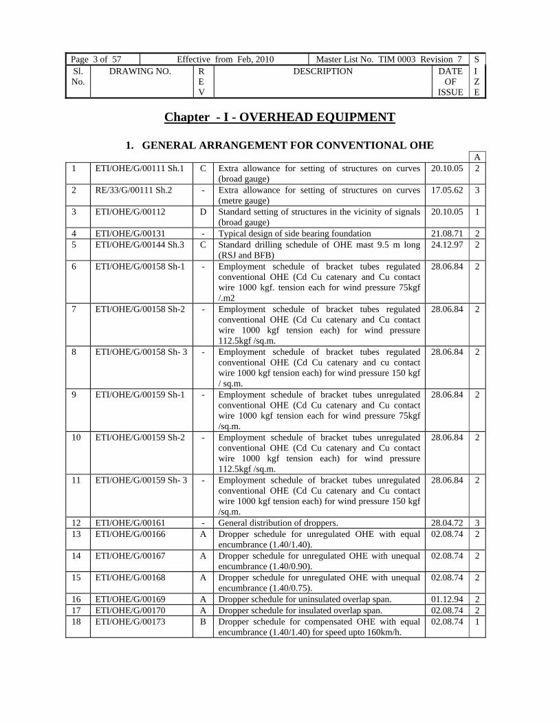
Chapter - I - OVERHEAD EQUIPMENT
1. GENERAL ARRANGEMENT FOR CONVENTIONAL OHE A
1 ETI/OHE/G/00111 Sh.1 C Extra allowance for setting of structures on curves (broad gauge)
20.10.05 2
2 RE/33/G/00111 Sh.2 - Extra allowance for setting of structures on curves (metre gauge)
17.05.62 3
3 ETI/OHE/G/00112 D Standard setting of structures in the vicinity of signals (broad gauge)
20.10.05 1
4 ETI/OHE/G/00131 - Typical design of side bearing foundation 21.08.71 2 5 ETI/OHE/G/00144 Sh.3 C Standard drilling schedule of OHE mast 9.5 m long
(RSJ and BFB) 24.12.97 2
6 ETI/OHE/G/00158 Sh-1 - Employment schedule of bracket tubes regulated conventional OHE (Cd Cu catenary and Cu contact wire 1000 kgf. tension each for wind pressure 75kgf /.m2
28.06.84 2
7 ETI/OHE/G/00158 Sh-2 - Employment schedule of bracket tubes regulated conventional OHE (Cd Cu catenary and Cu contact wire 1000 kgf tension each) for wind pressure 112.5kgf /sq.m.
28.06.84 2
8 ETI/OHE/G/00158 Sh- 3 - Employment schedule of bracket tubes regulated conventional OHE (Cd Cu catenary and cu contact wire 1000 kgf tension each) for wind pressure 150 kgf / sq.m.
28.06.84 2
9 ETI/OHE/G/00159 Sh-1 - Employment schedule of bracket tubes unregulated conventional OHE (Cd Cu catenary and Cu contact wire 1000 kgf tension each for wind pressure 75kgf /sq.m.
28.06.84 2
10 ETI/OHE/G/00159 Sh-2 - Employment schedule of bracket tubes unregulated conventional OHE (Cd Cu catenary and Cu contact wire 1000 kgf tension each) for wind pressure 112.5kgf /sq.m.
28.06.84 2
11 ETI/OHE/G/00159 Sh- 3 - Employment schedule of bracket tubes unregulated conventional OHE (Cd Cu catenary and Cu contact wire 1000 kgf tension each) for wind pressure 150 kgf /sq.m.
28.06.84 2
12 ETI/OHE/G/00161 - General distribution of droppers. 28.04.72 3 13 ETI/OHE/G/00166 A Dropper schedule for unregulated OHE with equal
encumbrance (1.40/1.40). 02.08.74 2
14 ETI/OHE/G/00167 A Dropper schedule for unregulated OHE with unequal encumbrance (1.40/0.90).
02.08.74 2
15 ETI/OHE/G/00168 A Dropper schedule for unregulated OHE with unequal encumbrance (1.40/0.75).
02.08.74 2
16 ETI/OHE/G/00169 A Dropper schedule for uninsulated overlap span. 01.12.94 2 17 ETI/OHE/G/00170 A Dropper schedule for insulated overlap span. 02.08.74 2 18 ETI/OHE/G/00173 B Dropper schedule for compensated OHE with equal
encumbrance (1.40/1.40) for speed upto 160km/h. 02.08.74 1

Page 4 of 57 Effective from Feb, 2010 Master List No. TIM 0003 Revision 7 SIZE
Sl. No.
DRAWING NO.
REV
DESCRIPTION
DATE OF
ISSUE
A 19 ETI/OHE/G/00173-1 - Dropper schedule for regulated OHE in worn out
condition of 107 sqmm contact wire (9.75mm thickness) 09.10.95 1
20 ETI/OHE/G/00174 B Dropper schedule for compensated OHE with unequal encumbrance (1.40/0.90) for speed upto 160km/h
03.04.80 2
21 ETI/OHE/G/00175 A Dropper schedule for compensated OHE with unequal encumbrance (1.40/0.75) for speed upto 160km/h
02.08.74 2
22 ETI/OHE/G/00176 D Dropper schedule for compensated OHE with unequal encumbrance (1.75/1.40) for speed upto 160km/h
02.08.74 2
23 ETI/OHE/G/00177 A Dropper schedule for conventional regulated OHE with zero presage (1400/1400)
05.09.94 2
24 RE/33/G/00181 A Outline of pantograph (BG & MG) 05.03.62 3 25 RE/33/G/00182 C Arrangement of pantograph multiple headed train BG 04.08.66 2 26 RE/33/G/00183 Sh. 1 B General clearance diagram on BG tracks (tangent and flat
curves ) 09.08.67 2
27 RE/33/G/00183 Sh. 2 - General clearance diagram on MG tracks (tangent and flat curves )
06.06.62 2
28 RE/33/G/00184 Sh. 1 A General clearance diagram on BG tracks (sharp curves ) 10.04.62 3 29 RE/33/G/00184 Sh. 2 - General clearance diagram on MG tracks (sharp curves ) 06.06.62 2 30 RE/33/G/00185 Sh. 1 A Restricted clearance diagram on tangent tracks BG 16.04.64 2 31 RE/33/G/00185 Sh. 2 - Restricted clearance diagram on MG tracks (tangent and
flat curves) 06.06.62 2
32 ETI/OHE/G/00186 Sh. 1
- Restricted clearance diagram on curved track on BG 14.01.83 2
33 RE/33/G/00186 Sh. 2 - Restricted clearance diagram on MG tracks (sharp curves)
06.06.82 2
34 ETI/OHE/G/00187 A Chart showing the blow off, push up and oscillations of the standard a.c. OHE
25.08.76 2
35 RE/33/G/00193 - Adjustment chart of regulating equipment winch type & pulley block type
27.01.67 1
36 ETI/OHE/G/00195 A Adjustment chart of regulating equipment three pulley type 3:1 ratio
28.06.94 2
37 RE/33/G/00197 A Cantilever adjustment chart at mean temperature 35 0C 31.01.61 1 38 ETI/OHE/G/00202 - Span and stagger chart (conventional OHE Cd copper
catenary and Cu contact wire) for wind pressure 75,112.5 & 150 kgf/sq. m
27.03.85 1
39 ETI/OHE/G/00222 Sh. 1
- Sag and tension chart for loaded catenary 11.09.72 1
40 RE/33/G/01101 Sh. 1 A General formation of single track in embankments and cuttings BG
07.09.62 3
41 RE/33/G/01101 Sh. 2 - General formation of single track in embankments and cuttings MG
06.04.62 3
42 RE/33/G/01102 Sh. 1 A General formation of double track in embankments and cuttings BG
07.04.62 2
43 RE/33/G/01102 Sh. 2 - General formation of double track in embankments and cuttings MG
06.04.62 2
44 RE/33/G/01103 Sh. 1 A General formation of multiple tracks BG 07.04.60 2 45 RE/33/G/01103 Sh. 2 - General formation of multiple tracks MG 06.04.62 2 46 RE/33/G/01104 Sh. 1 - Leading dimensions of turnouts BG 20.04.62 3 47 RE/33/G/01104 Sh. 2 - Leading dimensions of turnouts MG 17.05.62 2

Page 5 of 57 Effective from 31.12.2008 Master List No. TIM 0003 Revision 6 SIZE
Sl. No.
DRAWING NO. REV
DESCRIPTION DATE OF
ISSUE
A 48 RE/33/G/01105 Sh. 1 A Leading dimensions of crossing BG 20.04.62 3 49 RE/33/G/01105 Sh. 2 - Leading dimensions of diamond crossing MG 17.05.62 3 50 RE/33/G/01112 Sh. 2 - Normal profile of maximum moving dimensions MG 23.05.62 3 51 RE/33/G/01401 E Standard anchor arrangement 06.08.82 1 52 ETI/OHE/G/01402 B Anchor arrangement with dwarf mast 25.09.72 1 53 ETI/OHE/G/01403
Sh-1 D
Schedule of anchor block for BG. Tracks 13.08.99 2
54 ETI/OHE/G/01403 Sh-2
C Double guy rod arrangement with anchor block BG track 13.08.99 2
55 ETI/OHE/G/01403 Sh-3
B Schedule of anchor blocks for BG tracks (black cotton soil)
29.05.79 2
56 ETI/OHE/G/01502 - Trapezoidal counter weight arrangement on OHE structures
04.02.72 1
57 ETI/OHE/G/01503 Sh-1
B Cement concrete counter weight arrangements on OHE structures for winch type regulating equipment
30.04.91 1
58 ETI/OHE/G/01503 Sh-2
A Cement concrete counter weight arrangement on N, O & R type portal upright
30.04.91 2
59 ETI/OHE/G/01505 - Standard guide tube arrangement on a mast and structures 19.11.87 1 60 ETI/OHE/G/01601 - Arrangement of 3kV and 25kV pedestal insulator
supports on OHE masts and portals 03.02.72 1
61 ETI/OHE/G/01701 A Standard arrangements for mounting of number plate on OHE structures
23.03.85 0
62 ETI/OHE/G/01702 - Standard arrangement for mounting of number plate (Retro-reflective type) on OHE structures
23.02.98 0
63 ETI/OHE/G/02101 A Schematic arrangement of regulated OHE 04.07.94 64 ETI/OHE/G/02102 - Typical arrangement of OHE on cantilever mast for
double track section 22.06.81 2
65 ETI/OHE/G/02102 Sh-3 - Typical arrangement for fixing of bracket assembly on 9.5 m mast and structure to suit raising of track in future
05.01.77 2
66 ETI/OHE/G/02103 - General arrangement of OHE with stitch wire on catenary 06.05.72 2 67 ETI/OHE/G/02104 Sh-1 A Mast on platforms BG 20.01.73 2 68 RE/33/G/02104 Sh-2 A Mast on platforms MG 25.06.62 2 69 ETI/OHE/G/02106 Sh-1 A Details of bracket arrangement on tangent and curved
tracks 25.08.72 0
70 ETI/OHE/G/02106 Sh-3 C Details of bracket arrangement for OHE high speed 04.07.94 2 71 RE/33/G/02107 D Single bracket assembly on structures and dropped arms. 25.07.84 0 72 ETI/OHE/G/02108 A Box type cantilever arrangement 09.01.97 2 73 ETI/OHE/G/02111 A Arrangement of anticreep 04.07.94 2 74 ETI/OHE/G/02113 - Standard cantilever arrangement for boom anchor
anticreep location 27.01.69 1
75 ETI/OHE/G/02121 Sh-1 F Schematic arrangement of uninsulated overlap (Type I)
(3 and 4 span overlaps) 20.05.74 2
76 ETI/OHE/G/02121 Sh-4 A Schematic arrangement of uninsulated overlap (3 & 4
span overlaps) 04.07.94 1
77 ETI/OHE/G/02131 Sh-1 - Schematic arrangement of insulated overlap 25.09.87
1
78 ETI/OHE/G/02131 Sh-3 A Schematic arrangement of insulated overlap 04.07.94 1 79 ETI/OHE/G/02141 C General arrangement of regulated OHE at turn outs
(overlap and crossed type) 25.09.87 2

Page 6 of 57 Effective from Feb, 2010 Master List No. TIM 0003 Revision 7 SIZE
Sl. No.
DRAWING NO.
REV
DESCRIPTION
DATE OF
ISSUE
A 80 ETI/OHE/G/02151 - General arrangement of regulated OHE at cross over
(Overlap and crossed type) 13.02.98 1
81 ETI/OHE/G/02161 Sh-1 C Arrangement of neutral section 14.06.85 1 82 ETI/OHE/G/02161 Sh-2 - Arrangement of short neutral section 15.11.84 2 83 ETI/OHE/G/02162 - Arrangement of neutral section assembly (PTFE type ) at
switching station 01.12.88 2
84 ETI/OHE/G/03101 - Schematic arrangement of unregulated OHE 22.06.81 2 85 ETI/OHE/G/03121 E Standard termination of OHE (regulated and
unregulated) 11.03.03 1
86 ETI/OHE/G/03151 - General arrangement of unregulated OHE at turnout (crossed and overlap type)
16.10.82 2
87 ETI/OHE/G/03152 Sh-1 - General arrangement of unregulated OHE at cross over and diamond crossings (crossed and overlap type)
16.10.82 2
88 ETI/OHE/G/03152 Sh-2 - General arrangement of unregulated OHE at diamond crossings
16.10.82 2
89 ETI/OHE/G/03201 - General arrangement of head span 03.02.72 2 90 ETI/OHE/G/03301 A General arrangement of pull off 06.08.74 1 91 ETI/OHE/G/04201 - Span and stagger chart for tramway type OHE (regulated) 18.06.81 3 92 ETI/OHE/G/04202 Sh-1 C Drilling schedule of OHE mast 8.5m long RSJ and BFB
for tramway type OHE (regulated ) 22.01.98 2
93 ETI/OHE/G/04202 Sh-2 C Drilling schedule of OHE mast 9.0m long RSJ and BFB for tramway type OHE (regulated )
22.01.98 2
94 ETI/OHE/G/04203 C Schematic arrangement of tramway type OHE (regulated) 04.07.94 2 95 ETI/OHE/G/04204 B Arrangement of bracket assembly for tramway type OHE
(regulated) 21.06.85 3
96 ETI/OHE/G/04205 B Arrangement of anticreep for tramway type OHE (regulated)
04.07.94 3
97 ETI/OHE/G/04206 B Arrangement of anticreep for tramway type OHE (regulated) (alternative arrangement)
04.07.94 3
98 ETI/OHE/G/04207 Sh-1 B Arrangement of section insulator for tramway type OHE (regulated)
21.06.85 2
99 ETI/OHE/G/04207 Sh-2 B Small parts steel for supporting section insulator assembly. (for regulated tramway type OHE)
26.08.96 2
100 ETI/OHE/G/04208 - General arrangement of turnout for tramway type OHE (regulated)
18.06.81 3
101 ETI/OHE/G/04209 - Adjustment chart for tramway type OHE (regulated) 25.09.81 3 102 ETI/OHE/G/04212 B Standard termination of tramway type OHE (regulated
with pulley type regulating equipment) (3:1 ratio) 22.04.94
3
103 ETI/OHE/G/04213 - General arrangement of connections at switching stations
and BT locations for tramway type OHE. 22.04.94 3
104 ETI/OHE/G/05101 - In span jumper connection between catenary and contact wire.
15.01.72 3
105 ETI/OHE/G/05102 C Continuity jumper connection at un-insulated overlap. 10.07.01 1 106 ETI/OHE/G/05103 B Connection at turnouts. 25.07.84 2 107 ETI/OHE/G/05104 - Potential equalizer connection at insulated overlap and
neutral section. 15.01.72 2
108 ETI/OHE/G/05106 A Connection at diamond crossing. 12.01.83 3 109 ETI/OHE/G/05107 A Antitheft jumper. 28.10.94 2

Page 7 of 57 Effective from 31.12.2008 Master List No. TIM 0003 Revision 6 SIZE
Sl. No.
DRAWING NO. REV
DESCRIPTION DATE OF
ISSUE
A 110 ETI/OHE/G/05121 Sh-1 C General arrangement of connection to OHE by copper
cross feeder (150) 30.09.93
3
111 ETI/OHE/G/05122 Sh-1 C General arrangement of connection at switching station on double track section by copper cross feeder (150)
30.09.93 2
112 ETI/OHE/G/05123 Sh-1 C General arrangement of connection at switching station on multiple track section by copper cross feeder (150)
30.09.93 3
113 ETI/OHE/G/05143 B Suspension of 25 kV feeders (spider) on OHE masts. 14.06.85 1 114 RE/33/G/05145-1 A Termination of feeder, return conductor and return feeder
(copper and aluminium ) 04.04.03 1
115 RE/33/G/05152 C Arrangement of suspension of double spider 25 kV feeder and return feeder between sub-station and feeding station
13.05.86 2
116 RE/33/G/05181 C Assembly of section insulator 24.05.94 2 117 ETI/OHE/G/05201 A General arrangement of earth wire on OHE mast. 31.03.79 2 118 ETI/OHE/G/05201-1 - General arrangement of earth wire on OHE mast. 04.07.94 2 119 ETI/OHE/G/05251 A Arrangement of transverse bonds. 14.01.83 1 120 ETI/OHE/G/05306 F Connection of RC to track. 14.09.94 0 121 ETI/OHE/G/05307 B Suspension arrangement of aluminium return conductor
(spider) on traction structures. 30.10.92 2
122 ETI/OHE/G/05311 D Suspension of RC (spider) from boom of structures. 02.11.92 2 123 ETI/OHE/G/05312 A Suspension of RC (spider) from boom of structures with
clevis type disc insulator. 02.11.92 2
124 ETI/OHE/G/05413 B Connection between OHE and aluminium RC at booster station.
14.06.85 2
125 ETI/OHE/G/05513 Sh-1 A Mounting of 25 kV Isolators on OHE structures (general arrangement).
07.02.72 0
126 ETI/OHE/G/05513 Sh-2 A Details of small parts steel work for supporting 25 kV Isolators on new TTC boom.
07.02.72 0
127 ETI/OHE/G/05516 A Connection from Isolator to OHE. 30.09.93 1 128 ETI/OHE/G/05600 A Characteristics of conductor/bus bar for 25 kV ac
traction. 04.02.77 0
129 ETI/OHE/G/06000 B Suspension arrangement of AT feeder on traction mast
(for 2x25 kV). 03.01.92 2
130 ETI/OHE/G/06001 A Suspension arrangement of AT feeder on portals (For 2x25 kV).
03.01.92 1
131 ETI/OHE/G/06002 - Suspension arrangement of 25kv feeder at Switching station/Feeding post (for 2x25 kV).
23.10.89 2
132 ETI/OHE/G/06003 - Termination arrangement for AT feeder. 23.10.89 3 133 ETI/OHE/G/06004 B Arrangement of sectioning of AT feeder (for 2x25kV) 17.02.92 1 134 ETI/OHE/G/06005 Sh-1 - General arrangement of connections at an elementary
sectioning point on double track section (for 2x25kV) 28.11.91 3
135 ETI/OHE/G/06005 Sh-2 - Mounting details of double pole Isolator on mast(for 2x25kV)
28.11.91 1
136 ETI/OHE/G/06006
- Suspension of AT feeder (spider) from boom of portals (for 2x25kV AT system)
28.09.93
2
137 ETI/OHE/G/06008 - Mounting details of double pole Isolator on portals (for 2x25kV)
13.10.92
2
138 ETI/OHE/SK/124 B Span and stagger chart. 01.12.94 2

Page 8 of 57 Effective from Feb, 2010 Master List No. TIM 0003 Revision 7 SIZE
Sl. No.
DRAWING NO.
REV
DESCRIPTION
DATE OF
ISSUE
A 139 ETI/OHE/SK/148 - Dropper schedule for insulated overlap span (for higher
section of OHE). 22.11.94 3
140 ETI/OHE/SK/149 A Dropper schedule for uninsulated overlap span (for higher section of OHE).
01.12.94 3
141 ETI/OHE/SK/467 Arrangement for endurance and proof load test of regulating equipment (winch type )
06-08-84 2
142 ETI/OHE/SK/473 Sh.1 - Bracket arrangement on tangent track inside tunnel. 05.09.85 1 143 ETI/OHE/SK/473 Sh.2 - Bracket arrangement on curved track inside tunnel. 05.09.85 1 144 ETI/OHE/SK/473 Sh.3 - Detail of bracket arrangement inside tunnel. 05.09.85 1 145 ETI/OHE/SK/481 A Insulated Tee junction 26-09-96 2 146 ETI/OHE/SK/482 A Earthing clamp assembly 26-09-96 1 147 ETI/OHE/SK/521-1 Dropper schedule for regulated OHE in worn out
condition of 107 mm2 contact wire (10 mm thickness) 25.09.95 1
148 ETI/OHE/SK/522 - Dropper schedule for over lap’s spans. 05.02.88 1 149 ETI/OHE/SK/523 - Dropper schedule for anchor spans. 05.02.88 2 150 ETI/OHE/SK/524 A Counter weight assembly (1200/1200) 26.08.96 3 151 RE/33/531 A Bracket arrangement in tunnels with soft soil
(For DBK Rly projects) 28.04.65 3
152 ETI/OHE/SK/544 - Typical Sectioning diagram at station with Isolators. (For 2x25 kV).
26.09.89 3
153 ETI/OHE/SK/551 - Arrangement of neutral section for conversion with short neutral section.
24.01.90 1
154 ETI/OHE/SK/552 - Arrangement of short neutral section at existing feeding post.
24.01.90 2
155 ETI/OHE/SK/581 - Sag and tension chart for catenary (65mm2) and contact wire (107mm2) for 1200kgf/1200kgf tension.
02.02.94 2
156 ETI/OHE/SK/582 - Schematic arrangement of unined overlap. 02.02.94 2 157 ETI/OHE/SK/583 - Schematic arrangement of insulated overlap 02.02.94 2 158 ETI/OHE/SK/584 - Dropper schedule for regulated OHE (1200 kgf/1200 kgf
tension) 02.02.94 1
159 ETI/OHE/SK/585 - Dropper schedule for uninsulated overlap spans (1200kgf
/ 1200kgf tension) 02.02.94 2
160 ETI/OHE/SK/586 A Dropper schedule for insulated overlap spans (1200kgf / 1200kgf tension)
26.06.95 2
161 ETI/OHE/SK/587 A Counter weight assembly. 26.08.96 3 162 ETI/OHE/SK/588 - Counter weight eye rod. 02.02.94 2 163 ETI/OHE/SK/597 - Typical pneumatic circuit for raising/lowering of
pantograph from cab of OHE recording cum test car. 11.02.94 4
164 ETI/OHE/SK/603 - Schematic arrangement of uninsulated overlap (Three
spans and four spans). 15.12.94 2
165 ETI/OHE/SK/604 - Schematic arrangement of insulated overlap (Three spans
and four spans). 15.12.94 2
166 ETI/OHE/ SK/605 - Sag and tension chart ( higher section of OHE) 01.12.94 2 167 ETI/OHE/ SK/606 - Dropper schedule for regulated OHE (for higher section
of OHE) 01.12.94 2
168 ETI/OHE/ SK/607 - Schematic arrangement of uninsulated over lap (Three spans and four spans ) for higher section of OHE
01.12.94 2
169 ETI/OHE/ SK/608 - Schematic arrangement of insulated over lap (Three spans and four spans ) for higher section of OHE
01.12.94 2

Page 9 of 57 Effective from 31.12.2008 Master List No. TIM 0003 Revision 6 SIZE
Sl. No.
DRAWING NO. REV
DESCRIPTION DATE OF
ISSUE
A 170 ETI/OHE/ SK/609 - Schematic arrangement of uninsulated over lap (Three
spans and four spans) 01.12.94 2
171 ETI/OHE/ SK/610 - Schematic arrangement of insulated over lap (Three spans and four spans)
01.12.94 2
Chapter - I - OVERHEAD EQUIPMENT
2. ATD Series A
1. TI/DRG/OHE/ATD/ RDSO/00001/99/2
- Regulating equipment (three pulley type) 3:1 ratio (Modified)
29.08.06 1
2. TI/DRG/OHE/ATD/ RDSO/00002/99/3
- Part Details of Regulating equipment (three pulley type) 3:1 ratio (Modified)
15.05.07 0
3. TI/DRG/OHE/ATD/ RDSO/00003/99/0
- Adjustment chart of Regulating equipment (three pulley type) 3:1 ratio (Modified)
00-09-99 2
4. TI/DRG/OHE/ATD/ RDSO/00004/00/0
- Trapezoidal counter weight assembly 3:1 ratio. 19.06.01 1
5. TI/DRG/OHE/ATD/ RDSO/00005/02/1
- Clevis & Eye (Forged). 11.02.03 3
6. TI/DRG/OHE/ATD/ RDSO/00006/04/0
- Adjustment chart of Regulating equipment three pulley types (3:1 Ratio) old for composite OHE.
14.10.06 4
7. TI/DRG/OHE/ATD/ RDSO/00007/04/0
Adjustment chart of Regulating equipment three pulley type (3:1 Ratio) modified for composite OHE.
14.10.06 4
8. TI/DRG/OHE/ATD/ RDSO/00008/05/0
- Bolt M-18with castle nut. 30.06.05 4
9. TI/DRG/OHE/ATD/ RDSO/00009/05/0
Fixing arrangement of mast Anchor fitting for Anti falling device in three pulley (Mod) ATD
27.09.06 2

Page 10 of 57 Effective from Feb, 2010 Master List No. TIM 0003 Revision 7 SIZE
Sl. No.
DRAWING NO.
REV
DESCRIPTION
DATE OF
ISSUE
Chapter - I - OVERHEAD EQUIPMENT
3. COMPONENTS, FITTINGS, EQUIPMENTS AND SMALL PART STEEL WORKS (SPS)
A 1 ETI/OHE/P/150 - High tensile rustles ‘U’ bolt 10 mm dia. 19.09.74 3 2 RE/33/P/160 A High tensile rustles pin bolt 10 mm dia. 01.06.65 3 3 RE/33/P/250 B Steel ‘U’ bolt and nuts dia 14 mm 03.08.74 3 4 RE/33/P/260 C Snap head pin dia 20 mm 30.06.95 3 5 RE/33/P/500 - Rail jumper assembly 01.09.59 2 6 RE/33/P/501 B Rail jumper clamp body grip screw and ferrule nut 14.02.61 2 7 RE/33/P/504 A Rail jumper ferrule 14.02.61 3 8 RE/33/P/509 - Rail jumper extension 06.05.60 2 9 RE/33/P/510 A Earthing rods 11.01.61 3 10 RE/33/P/511 - Earthing rods 06.05.60 1 11 RE/33/P/520 A Earthing rod hook assembly 24.01.61 3 12 RE/33/P/521 - Earthing rod head 24.01.61 3 13 RE/33/P/522 - Earthing rod tongue 24.01.61 3 14 RE/33/P/523 - Earthing rod hook pin and other small parts 24.01.61 3 15 RE/33/P/530 - Insulated Tee junction 22.03.60 1 16 RE/33/P/550 - Automatic come-along clamp (for contact wire) 22.01.62 1 17 RE/33/P/560 - Automatic come- along clamp 25.06.65 1 18 ETI/OHE/P/580 - Contact wire straightener assembly. 11.03.70 2 19 ETI/OHE/P/581-599 - Details of contact wire straightener. 11.03.70 0 20 ETI/OHE/P/1009 A Terminal connector (19mm) multiple holes
(bolted type) 10.03.05 3
21 ETI/OHE/P/1010 A Terminal connector (15mm) multiple holes (bolted type) 10.03.05 2 22 ETI/OHE/P/1030-2 D Contact wire parallel clamp large 17.07.91 3 23 ETI/OHE/P/1030-3 A Parallel Clamp (157-65/ 107/150 ) for WKRE 23.08.91 2 24 ETI/OHE/P/1031-2 C Contact wire parallel clamp part large 24.01.01 3 25 ETI/OHE/P/1040-2 E Contact wire parallel clamp part small 17.07.91 3 26 ETI/OHE/P/1040-3 B Parallel Clamp (90/50) 19.06.01 3 27 ETI/OHE/P/1041-2 C Contact wire parallel clamp part small 19.06.01 2 28 ETI/OHE/P/1050-2 D Parallel Clamp (150/105-150) for WKRE 23.08.91 3 29 ETI/OHE/P/1050-3 A Parallel Clamp (150/160) for WKRE 19.06.01 2 30 ETI/OHE/P/1051-2 C Parallel Clamp part (150/105-150) 19.06.01 3 31 ETI/OHE/P/1070-1 B Bridle wire Clamp (6mm) with two bolts 09.06.95 2 32 ETI/OHE/P/1080 A Contact wire splice (107) 01.06.88 2 33 ETI/OHE/P/1080-1 B Contact wire splice (toothed type) 01.06.88 2 34 ETI/OHE/P/1081-1 C Contact wire splice part 17.11.87 2 35 ETI/OHE/P/1081-2 A Contact wire splice part 19.03.87 2 36 ETI/OHE/P/1090 - Catenary splice (65) 29.06.71 3 37 ETI/OHE/P/1091 - Catenary splice sleeve 29.06.71 3 38 ETI/OHE/P/1092 - Catenary joint socket 29.06.71 3 39 ETI/OHE/P/1093 - Catenary joint socket left 29.06.71 3 40 ETI/OHE/P/1094 A Catenary joint cone 08.10.84 3 41 ETI/OHE/P/1102 - Feeder joint socket 03.10.72 3

Page 11 of 57 Effective from 31.12.2008 Master List No. TIM 0003 Revision 6 SIZE
Sl. No.
DRAWING NO. REV
DESCRIPTION DATE OF
ISSUE
A42 ETI/OHE/P/1104 - Feeder joint cone 02.08.96 3 43 ETI/OHE/P/1110-2 D Contact wire ending clamp (107) 01.06.88 2 44 ETI/OHE/P/1120 B Catenary ending clamp (65) 01.06.88 3 45 ETI/OHE/P/1120-1 A Catenary ending clamp (65) wedge type 07.12.93 1 46 ETI/OHE/P/1121 - Catenary ending clamp body 20.08.71 3 47 ETI/OHE/P/1130 - Feeder ending clamp (150) 25.09.87 3 48 ETI/OHE/P/1131 - Feeder ending clamp body 19.08.71 3 49 ETI/OHE/P/1140 B Large span wire ending clamp (130) 01.06.88 3 50 ETI/OHE/P/1143 B Large span wire joint cone. 20.10.00 3 51 RE/33/P/1160 J Suspension clamp 01.06.88 2 52 RE/33/P/1161 E Suspension clamp body 03.09.84 2 53 RE/33/P/1163 D Suspension clamp lock plate 13.09.65 3 54 RE/33/P/1170 K Double suspension clamp 01.06.88 2 55 RE/33/P/1171 F Double suspension clamp body 03.09.84 2 56 RE/33/P/1172 C Double suspension lock plate 04.02.78 3 57 RE/33/P/1174 B Packing saddle 08.01.87 3 58 RE/33/P/1180 F Contact wire dropper clip (107) 18.01.94 3 59 RE/33/P/1181 G Contact wire dropper clip part 18.01.94 3 60 RE/33/P/1182 C Locking wire 06.11.69 3 61 ETI/OHE/P/1190 B Catenary dropper assembly. 01.06.88 3 62 ETI/OHE/P/1191 - Catenary dropper link. 08.11.85 3 63 ETI/OHE/P/1192 C Catenary dropper clip. 01.06.88 3 64 ETI/OHE/P/1193 - Dropper. 08.11.85 3 65 ETI/OHE/P/1194 A Bridle wire dropper clip. 01.06.88 3 66 ETI/OHE/P/1210-2 C Knuckle assembly. 03.06.88 2 67 ETI/OHE/P/1216 D Knuckle tube clamp. 03.06 88 3 68 RE/33/P/1220 E Contact wire swivel clip 06.11.69 3 69 RE/33/P/1221 D Contact wire swivel clip part 27.04.74 2 70 RE/33/P/1222 C Contact wire swivel clip pin 06.11.69 3 71 ETI/OHE/P/1230 - Standard contact wire crossing assembly. 01.1174 3 72 ETI/OHE/P/1233 - Contact wire crossing bar. 01.11.74 3 73 RE/33/P/1250 D Double contact wire swivel clip 06.11.69 3 74 RE/33/P/1251 A Double contact wire swivel clip part 16.07.65 1 75 ETI/OHE/P/1260-1 A Strain clamp link assembly 11.03.96 3 76 ETI/OHE/P/1263 - Strain clamp link. 09.08.74 3 77 RE/33/P/1270-1 F Suspension clevis assembly (18 mm) 03.06.88 3 78 RE/33/P/1280 C Double contact wire splice 03.06.88 2 79 ETI/OHE/P/1310 - Pull off Clamp assembly. 12.12.72 3 80 ETI/OHE/P/1320 B ‘U Clamp (50/50) 03.06.88 3 81 ETI/OHE/P/1330 B ‘U Clamp (50) 03.06.88 3 82 ETI/OHE/P/1350 - Thimble (10mm) 01.01.73 3 83 ETI/OHE/P/1360 B Steel wire Ending Clamp (90) 03.06.88 3 84 ETI/OHE/P/1361 A Steel wire joint socket. 18.02.74 3 85 ETI/OHE/P/1362 B Steel wire joint cone. 09.10.84 3 86 ETI/OHE/P/1370-1 F Raised register arm clamp. 08.05.00 2 87 ETI/OHE/P/1370-2 - Raised register arm Clamp (150 FB). 01.12.94 2 88 ETI/OHE/P/1390-1 D Crossing clamp. 26.09.88 3 89 ETI/OHE/P/1391-1 B Crossing clamp piece. 01.05.79 3

Page 12 of 57 Effective from Feb, 2010 Master List No. TIM 0003 Revision 7 SIZE
Sl. No.
DRAWING NO.
REV
DESCRIPTION
DATE OF
ISSUE
A90 ETI/OHE/P/1400 C Short dropper assembly. 10.01.89 2 91 ETI/OHE/P/1410 B Special dropper assembly. 25.05.88 3 92 ETI/OHE/P/1530-1 C Parallel clamp (105/240) for dc OHE. 19.06.01 2 93 ETI/OHE/P/1540 D Bimetallic parallel clamp (10/20). 10.01.89 2 94 ETI/OHE/P/1550 E Parallel clamp (20/20). 10.01.89 2 95 ETI/OHE/P/1560 D Bimetallic parallel clamp (15/20). 10.01.89 2 96 ETI/OHE/P/1580 Sh.1 F Large suspension clamp 20mm. 10.03.92 2 97 ETI/OHE/P/1580 Sh.2 - Large suspension clamp 20mm (with armour rod). 02.11.92 2 98 ETI/OHE/P/1600 C Strain clamp 20 mm. 07.07.88 2 99 ETI/OHE/P/1610-1 - Compression joint. 06.08.82 3 100 ETI/OHE/P/1611 B Compression joint (spider). 01.11.74 2 101 ETI/OHE/P/1640 - Repair sleeves (compression type). 01.11.74 3 102 ETI/OHE/P/1790 C Contact wire ending clamp (150) (for WKRE/dc OHE). 01.12.94 2 103 RE/33/P/2041 D Standard bracket tube Dia. 30/38 22.02.84 3 104 ETI/OHE/P/2060 - Tube cap. 21.11.85 3 105 ETI/OHE/P/2064-1 A Tube cap 30mm. 10.01.89 3 106 RE/33/P/2081 E Large bracket tube Dia 40/49 mm 25.02.84 3 107 RE/33/P/2086 C Large bracket sleeve 25.02.84 3 108 ETI/OHE/P/2104-1 A Tube cap 40mm. 10.01.89 3 109 ETI/OHE/P/2110 B Standard catenary suspension bracket. 03.06.88 3 110 ETI/OHE/P/2110-1 D Standard catenary suspension bracket. 03.06.88 1 111 ETI/OHE/P/2111 B Standard catenary suspension bracket bottom. 22.11.85 2 112 ETI/OHE/P/2112 A Standard catenary suspension bracket top 05.09.84 3 113 ETI/OHE/P/2120 B Standard catenary direct clamp 03.06.88 2 114 ETI/OHE/P/2121 A Standard catenary direct clamp top 04.09.84 3 115 ETI/OHE/P/2122 A Standard catenary direct clamp bottom 04.09.84 3 116 ETI/OHE/P/2123 C Direct catenary clamp grip. 22.11.85 3 117 ETI/OHE/P/2124 B Direct catenary clamp stud 03.06.88 3 118 ETI/OHE/P/2125 B Bridle wire sleeve. 01.12.88 3 119 ETI/OHE/P/2130 B Large catenary suspension bracket. 03.06.88 3 120 ETI/OHE/P/2130-1 C Large catenary suspension bracket. 03.06.88 1 121 ETI/OHE/P/2131 B Large catenary suspension bracket top. 22.11.85 3 122 ETI/OHE/P/2132 B Large catenary suspension bracket bottom. 22.11.85 2 123 ETI/OHE/P/2140 C Catenary direct clamp (large) 03.06.88 2 124 ETI/OHE/P/2141 B Large catenary direct clamp top. 05.09.84 3 125 ETI/OHE/P/2142 B Large catenary direct clamp bottom 22.11.85 3 126 ETI/OHE/P/2150-1 E Standard register arm hook 03.06.88 3 127 ETI/OHE/P/2151-1 C Register arm hook top 02.05.79 3 128 ETI/OHE/P/2152-1 C Register arm hook bottom 02.05.79 3 129 ETI/OHE/P/2160-1 E Large register arm hook 03.06.88 3 130 ETI/OHE/P/2161-1 C Large register arm hook top 02.05.79 3 131 ETI/OHE/P/2162-1 C Large register arm hook bottom 02.05.79 3 132 ETI/OHE/P/2270-4 E 38mm register arm dropper assembly 07.07.88 3 133 ETI/OHE/P/2270-5 E 49mm register arm dropper assembly 07.07.88 3 134 ETI/OHE/P/2274-1 D Dropper clip (38mm) for standard bracket tube 07.07.88 3 135 ETI/OHE/P/2277 D Dropper clip (49mm) for large bracket tube 07.07.88 3 136 ETI/OHE/P/2340 C Steady rod 11.03.96 2 137 ETI/OHE/P/2341 B Steady rod piece 11.03.96 2

Page 13 of 57 Effective from 31.12.2008 Master List No. TIM 0003 Revision 6 SIZE
Sl. No.
DRAWING NO. REV
DESCRIPTION DATE OF
ISSUE
A138 ETI/OHE/P/2345 - Steady rod eye piece 03.10.72 3 139 ETI/OHE/P/2345-1 - Double Vee suspension top eye piece 18.02.66 3 140 ETI/OHE/P/2352 A Bent steady arm swivel 11.03.96 3 141 ETI/OHE/P/2360 L 25mm drop bracket assembly 19.07.88 3 142 ETI/OHE/P/2380 C Hook bracket 19.07.88 2 143 ETI/OHE/P/2390 B BFB steady arm assembly. 09.05.79 2 144 ETI/OHE/P/2391 G Steady arm hook (BFB) 19.11.99 2 145 TI/DRG/OHE/FTGFE/
RDSO/00003/00/0 - Steady arm hook BFB (Forged) 29.09.00 3
146 ETI/OHE/P/2392 C BFB steady arm swivel. 04.04.90 1 147 RE/33/P/2400 E Tubular stay arm 19.08.66 3 148 RE/33/P/2401 C Stay tube (25 mm) 18.06.66 2 149 ETI/OHE/P/2402 A Tubular stay adjuster. 25.09.72 2 150 ETI/OHE/P/2402-1 B Tubular stay adjuster (large) 04.04.90 3 151 ETI/OHE/P/2403-1 C Tubular stay sleeve. 04.03.05 3 152 TI/DRG/OHE/FTGFE/
RDSO/00004/03/0 - Tubular stay sleeve (Forged). 17.11.03 2
153 ETI/OHE/P/2404 C Stud bolt (10mm) 08.02.77 2 154 ETI/OHE/P/2410 - 25mm register arm dropper assembly. 04.07.94 3 155 ETI/OHE/P/2420-1 A Register arm assembly for mast on platforms. 14.06.85 3 156 RE/33/P/2421 C Register arm tube 25mm 25.02.84 3 157 RE/33/P/2422-1 B Register arm eye piece 25mm 26.08.88 3 158 TI/DRG/OHE/FTGFE/
RDSO/00002/00/0 - Register arm eye piece 25mm(Forged) 27.07.00
159 ETI/OHE/P/2423-1 A Tube cap 25mm. 10.01.89 3 160 RE/33/P/2431 D Raised register arm tube 25 mm 25.02.84 3 161 RE/33/P/2432 E Raised register arm adjuster 25 mm 11.03.96 2 162 ETI/OHE/P/2440 - 38mm register arm dropper assembly 04.07.94 3 163 ETI/OHE/P/2450 - 49mm register arm dropper assembly 04.07.94 2 164 ETI/OHE/P/2460 E 25mm register arm dropper assembly. 07.07.88 3 165 ETI/OHE/P/2461-1 F Dropper clip (34mm ) for register arm tube. 07.07.88 3 166 ETI/OHE/P/2462-1 A Register arm dropper 19.09.85 3 167 ETI/OHE/P/2463 A Register arm dropper loop. 19.09.85 3 168 ETI/OHE/P/2464 - Register arm dropper loop (short) 18.03.71 3 169 ETI/OHE/P/2465 B Register arm dropper loop. 19.09.85 3 170 ETI/OHE/P/2470 E Raised register arm dropper assembly. 07.07.88 3 171 ETI/OHE/P/2471-1 E Dropper clip (25) for raised register arm. 07.07.88 3 172 ETI/OHE/P/2472-1 B Raised register arm dropper 19.09.85 3 173 ETI/OHE/P/2480 - Raised register arm dropper assembly 04.07.94 2 174 ETI/OHE/P/2490-2 E 25mm steady arm clamp 07.07.88 3 175 ETI/OHE/P/2520 B Normal bent steady arm. 11.03.96 1 176 ETI/OHE/P/2522 B Normal bent steady arm eye piece. 06.05.86 3 177 ETI/OHE/P/2523 B Normal bent steady arm hook. 14.10.92 3 178 ETI/OHE/P/2540 B BFB steady arm assembly. 19.08.70 2 179 ETI/OHE/P/2540-1 - BFB steady arm assembly for tramway OHE (regulated). 09.06.81 2 180 ETI/OHE/P/2541 E BFB steady arm eye piece. 14.10.92 3 181 ETI/OHE/P/2542 C BFB steady arm swivel 04.04.90 3 182 ETI/OHE/P/2550-1/2 L Standard antiwind clamp. 11.03.96 3
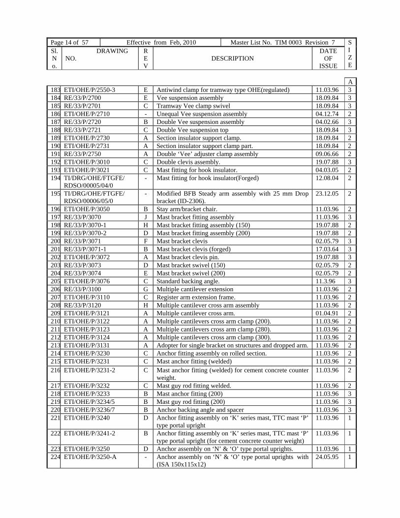
Page 14 of 57 Effective from Feb, 2010 Master List No. TIM 0003 Revision 7 SIZE
Sl. No.
DRAWING NO.
REV
DESCRIPTION
DATE OF
ISSUE
A183 ETI/OHE/P/2550-3 E Antiwind clamp for tramway type OHE(regulated) 11.03.96 3 184 RE/33/P/2700 E Vee suspension assembly 18.09.84 3 185 RE/33/P/2701 C Tramway Vee clamp swivel 18.09.84 3 186 ETI/OHE/P/2710 - Unequal Vee suspension assembly 04.12.74 2 187 RE/33/P/2720 B Double Vee suspension assembly 04.02.66 3 188 RE/33/P/2721 C Double Vee suspension top 18.09.84 3 189 ETI/OHE/P/2730 A Section insulator support clamp. 18.09.84 2 190 ETI/OHE/P/2731 A Section insulator support clamp part. 18.09.84 2 191 RE/33/P/2750 A Double ‘Vee’ adjuster clamp assembly 09.06.66 2 192 ETI/OHE/P/3010 C Double clevis assembly. 19.07.88 3 193 ETI/OHE/P/3021 C Mast fitting for hook insulator. 04.03.05 2 194 TI/DRG/OHE/FTGFE/
RDSO/00005/04/0 - Mast fitting for hook insulator(Forged) 12.08.04 2
195 TI/DRG/OHE/FTGFE/ RDSO/00006/05/0
- Modified BFB Steady arm assembly with 25 mm Drop bracket (ID-2306).
23.12.05 2
196 ETI/OHE/P/3050 B Stay arm/bracket chair. 11.03.96 2 197 RE/33/P/3070 J Mast bracket fitting assembly 11.03.96 3 198 RE/33/P/3070-1 H Mast bracket fitting assembly (150) 19.07.88 2 199 RE/33/P/3070-2 D Mast bracket fitting assembly (200) 19.07.88 2 200 RE/33/P/3071 F Mast bracket clevis 02.05.79 3 201 RE/33/P/3071-1 B Mast bracket clevis (forged) 17.03.64 3 202 ETI/OHE/P/3072 A Mast bracket clevis pin. 19.07.88 3 203 RE/33/P/3073 D Mast bracket swivel (150) 02.05.79 2 204 RE/33/P/3074 E Mast bracket swivel (200) 02.05.79 2 205 ETI/OHE/P/3076 C Standard backing angle. 11.3.96 3 206 RE/33/P/3100 G Multiple cantilever extension 11.03.96 2 207 ETI/OHE/P/3110 C Register arm extension frame. 11.03.96 2 208 RE/33/P/3120 H Multiple cantilever cross arm assembly 11.03.96 2 209 ETI/OHE/P/3121 A Multiple cantilever cross arm. 01.04.91 2 210 ETI/OHE/P/3122 A Multiple cantilevers cross arm clamp (200). 11.03.96 2 211 ETI/OHE/P/3123 A Multiple cantilevers cross arm clamp (280). 11.03.96 2 212 ETI/OHE/P/3124 A Multiple cantilevers cross arm clamp (300). 11.03.96 2 213 ETI/OHE/P/3131 A Adopter for single bracket on structures and dropped arm. 11.03.96 2 214 ETI/OHE/P/3230 C Anchor fitting assembly on rolled section. 11.03.96 2 215 ETI/OHE/P/3231 C Mast anchor fitting (welded) 11.03.96 2 216 ETI/OHE/P/3231-2 C Mast anchor fitting (welded) for cement concrete counter
weight. 11.03.96 2
217 ETI/OHE/P/3232 C Mast guy rod fitting welded. 11.03.96 2 218 ETI/OHE/P/3233 B Mast anchor fitting (200) 11.03.96 3 219 ETI/OHE/P/3234/5 B Mast guy rod fitting (200) 11.03.96 3 220 ETI/OHE/P/3236/7 B Anchor backing angle and spacer 11.03.96 3 221 ETI/OHE/P/3240 D Anchor fitting assembly on ‘K’ series mast, TTC mast ‘P’
type portal upright 11.03.96 1
222 ETI/OHE/P/3241-2 B Anchor fitting assembly on ‘K’ series mast, TTC mast ‘P’ type portal upright (for cement concrete counter weight)
11.03.96 1
223 ETI/OHE/P/3250 D Anchor assembly on ‘N’ & ‘O’ type portal uprights. 11.03.96 1 224 ETI/OHE/P/3250-A - Anchor assembly on ‘N’ & ‘O’ type portal uprights with
(ISA 150x115x12) 24.05.95 1

Page 15 of 57 Effective from 31.12.2008 Master List No. TIM 0003 Revision 6 SIZE
Sl. No.
DRAWING NO. REV
DESCRIPTION DATE OF
ISSUE
A225 ETI/OHE/P/3260 G Boom anchor assembly on ‘N’ & ‘O type portals 11.03.96 2 226 ETI/OHE/P/3270 A Anchor assembly on BFB portal upright 28.09.88 1 227 ETI/OHE/P/3280 A Anchor assembly on G Type portal upright 28.09.88 1 228 ETI/OHE/P/3290 A Anchor assembly on R Type portal upright 28.09.88 1 229 ETI/OHE/P/3300 A Clamps and plates for mounting of number plate on OHE
structures. 18.03.86 1
230 ETI/OHE/P/3310 - Anchor fitting assembly on K series, TTC masts & P type portal uprights (with ISA 150x115x12).
24.09.93 1
231 ETI/OHE/P/3320 - Anchor fitting assembly on TM series masts (with ISA 150x115x12)
10.11.94 1
232 ETI/OHE/P/3330 - Clamp and plates for Mounting of number plates (retro- reflective type) on OHE structures.
10.03.98 1
233 TI/DRG/OHE/FTGNF/ RDSO/00001/02/1
- Terminal clamp (15 mm) compression type. 04.03.05 3
234 TI/DRG/OHE/FTGNF/ RDSO/00002/02/1
- Terminal clamp (19 mm) compression type. 04.03.05 3
235 TI/DRG/OHE/FTGNF/ RDSO/00003/03/0
- Feeder splice (150) 25.03.03 3
236 TI/DRG/OHE/FTGNF/ RDSO/00004/03/0
- Feeder splice sleeve. 25.03.03 3
237 TI/DRG/OHE/FTGNF/ RDSO/00005/03/0
- Feeder joint socket left. 25.03.03 3
238 TI/DRG/OHE/FTGNF/ RDSO/00006/03/0
- 18mm Bus terminal clamp (Compression type). 27.11.03 3
239 TI/DRG/OHE/FTGNF/ RDSO/00007/06/0
- Parallel clamp (Dia 20 mm/18.75mm). 01.02.06 2
240 ETI/OHE/P/4001 A Span wire clip (65) 10.03.92 3 241 ETI/OHE/P/4002 A Span wire clip (130) 10.03.92 3 242 RE/33/P/4010-1 H Cross span suspension clamp 28.09.98 3 243 RE/33/P/4011-1 E Cross span suspension clamp clevis 01.05.79 3 244 RE/33/P/4012-1 D Cross span suspension clamp part 01.05.79 3 245 RE/33/P/4013-1 C Cross span suspension clamp crank 16.08.74 3 246 RE/33/P/4030 E Steady wire clamp 28.09.88 3 247 RE/33/P/4031 C Steady wire clamp part 19.09.84 3 248 ETI/OHE/P/4036 - ‘U’ bolt saddle. 30.01.73 3 249 RE/33/P/4080 D Head span mast fitting assembly (200 mm) 13.08.74 2 250 RE/33/P/4090 C Head span mast fitting assembly (250 mm) 13.08.74 2 251 RE/33/P/4100 E Head span mast fitting assembly (300 mm) 28.09.88 2 252 ETI/OHE/P/4110 C Head span mast fitting assembly (450 mm) 28.09.88 2 253 ETI/OHE/P/5000 B Guy rod assembly 17.05.96 2 254 ETI/OHE/P/5001/5001-1 D Anchor bolt 17.05.96 2 255 ETI/OHE/P/5001-3 C Anchor bolt 17.05.96 3 256 ETI/OHE/P/5002 B Guy rod stirrup. 4.04.90 2 257 ETI/OHE/P/5004/5/6-1 G Guy rod dia 25mm. 17.05.96 3 258 ETI/OHE/P/5007-1 B Anchor ‘V’ bolt. 17.05.96 3 259 ETI/OHE/P/5008 B Anchor loop. 17.05.96 3 260 ETI/OHE/P/5011 A 5 tonne buckle 19.09.85 2 261 ETI/OHE/P/5012 B 5 tonne eye bolt right. 11.04.89 3

Page 16 of 57 Effective from Feb, 2010 Master List No. TIM 0003 Revision 7 SIZE
Sl. No.
DRAWING NO.
REV
DESCRIPTION
DATE OF
ISSUE
A262 ETI/OHE/P/5013 B 5 tonne eye bolt left. 11.04.89 2 263 ETI/OHE/P/5020 B 9 tonne adjuster 11.04.89 2 264 ETI/OHE/P/5020-1 - 9 tonne adjuster (eye and clevis type) 09.04.92 2 265 ETI/OHE/P/5020-2 - 9 tonne adjuster (double clevis type) 24.08.92 2 266 ETI/OHE/P/5021 A 9 tonne turn buckle. 19.09.85 2 267 ETI/OHE/P/5022 B 9 tonne eye bolt left 11.04.89 3 268 ETI/OHE/P/5023 B 9 tonne eye bolt right. 11.04.89 3 269 ETI/OHE/P/5024 - 9 tonne clevis bolt – Left. 09.04.92 3 270 ETI/OHE/P/5025 - 9 tonne clevis bolt – Right 24.08.92 3 271 ETI/OHE/P/5030 C Anchor double strap assembly. 11.04.89 3 272 ETI/OHE/P/5040 B 18mm single clevis assembly 11.04.89 3 273 TI/DRG/OHE/FTGFE/
RDSO/00001/00/0 - 18mm single clevis assembly modified 20.07.00 2
274 ETI/OHE/P/5060-2 C Standard guide tube assembly. 17.05.96 3 275 ETI/OHE/P/5064/65/66 B Details of guide tube attachment for trapezoidal counter
weight. 17.05.96 3
276 ETI/OHE/P/5064-1/64-2 A Guide tube bracket angle (welded) for attachment on BFB mast and portal (for trapezoidal counter weight).
17.05.96 3
277 ETI/OHE/P/5090 C Counter weight assembly. 24.08.00 3 278 ETI/OHE/P/5090-1 D Trapezoidal counter weight assembly. 24.08.00 3 279 ETI/OHE/P/5090-3 F Counter weight assembly (light). 24.08.00 2 280 ETI/OHE/P/5090-4 F Cement concrete counter weight assembly. 17.05.96 1 281 ETI/OHE/P/5090-5 B Counter weight assembly for regulating equipment (3:1) 24.08.00 2 282 ETI/OHE/P/5090-6 B Counter weight assembly (for tramway type OHE) ( 1250
kgf) 24.08.00 3
283 ETI/OHE/P/5091 B Cast iron base weight. 24.08.00 3 284 ETI/OHE/P/5092/93 B Counter weight piece. 24.08.00 3 285 ETI/OHE/P/5094/95 F Counter weight piece eye rod 04.04.90 2 286 ETI/OHE/P/5128 A Regulating rope and fitting. 10.04.89 2 287 ETI/OHE/P/5183 C Double eye distance rod (dia 20mm) 04.04.90 3 288 ETI/OHE/P/5190-1 C Compensating plate assembly. 22.07.96 3 289 ETI/OHE/P/5190-2 C Equalizing plate assembly. 22.07.96 3 290 ETI/OHE/P/5191 B Compensating plate. 22.07.96 3 291 ETI/OHE/P/5191-1/2 D Compensating plate. 01.12.94 3 292 ETI/OHE/P/5192 B Equalizing plate. 22.07.96 3 293 ETI/OHE/P/5192-1/2 C Equalizing plate ( for WKRE) 01.12.94 3 294 ETI/OHE/P/5193 B Short equalizing plate. 22.07.96 3 295 ETI/OHE/P/5194-1 - Compensating plate assembly 01.12.94 3 296 ETI/OHE/P/5195-2 A Equalizing plate assembly 26.08.96 3 297 ETI/OHE/P/5220 F Guy rod double strap assembly. 04.04.90 3 298 ETI/OHE/P/5221/2 D Guy rod double strap 04.04.90 3 299 ETI/OHE/P/5300 H Regulating equipment (winch type) 5:1 ratio. 26.06.98 1 300 ETI/OHE/P/5311 B Drum 25.08.87 0 301 ETI/OHE/P/5312/15/21/31 D Part detail of regulating equipment (winch type). 22.07.96 1
302 ETI/OHE/P/5314/16-1/17-
1/23/24/33-36 B Part detail of regulating equipment (winch type.) 22.07.96 2
303 ETI/OHE/P/5313/32 A Axles 05.11.84 3
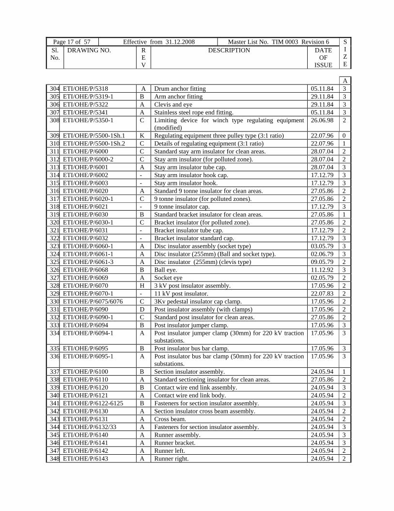
Page 17 of 57 Effective from 31.12.2008 Master List No. TIM 0003 Revision 6 SIZE
Sl. No.
DRAWING NO. REV
DESCRIPTION DATE OF
ISSUE
A304 ETI/OHE/P/5318 A Drum anchor fitting 05.11.84 3 305 ETI/OHE/P/5319-1 B Arm anchor fitting 29.11.84 3 306 ETI/OHE/P/5322 A Clevis and eye 29.11.84 3 307 ETI/OHE/P/5341 A Stainless steel rope end fitting. 05.11.84 3 308 ETI/OHE/P/5350-1 C Limiting device for winch type regulating equipment
(modified) 26.06.98 2
309 ETI/OHE/P/5500-1Sh.1 K Regulating equipment three pulley type (3:1 ratio) 22.07.96 0 310 ETI/OHE/P/5500-1Sh.2 C Details of regulating equipment (3:1 ratio) 22.07.96 1 311 ETI/OHE/P/6000 C Standard stay arm insulator for clean areas. 28.07.04 2 312 ETI/OHE/P/6000-2 C Stay arm insulator (for polluted zone). 28.07.04 2 313 ETI/OHE/P/6001 A Stay arm insulator tube cap. 28.07.04 3 314 ETI/OHE/P/6002 - Stay arm insulator hook cap. 17.12.79 3 315 ETI/OHE/P/6003 - Stay arm insulator hook. 17.12.79 3 316 ETI/OHE/P/6020 A Standard 9 tonne insulator for clean areas. 27.05.86 2 317 ETI/OHE/P/6020-1 C 9 tonne insulator (for polluted zones). 27.05.86 2 318 ETI/OHE/P/6021 - 9 tonne insulator cap. 17.12.79 3 319 ETI/OHE/P/6030 B Standard bracket insulator for clean areas. 27.05.86 1 320 ETI/OHE/P/6030-1 C Bracket insulator (for polluted zone). 27.05.86 2 321 ETI/OHE/P/6031 - Bracket insulator tube cap. 17.12.79 2 322 ETI/OHE/P/6032 - Bracket insulator standard cap. 17.12.79 3 323 ETI/OHE/P/6060-1 A Disc insulator assembly (socket type) 03.05.79 3 324 ETI/OHE/P/6061-1 A Disc insulator (255mm) (Ball and socket type). 02.06.79 3 325 ETI/OHE/P/6061-3 A Disc insulator (255mm) (clevis type) 09.05.79 2 326 ETI/OHE/P/6068 B Ball eye. 11.12.92 3 327 ETI/OHE/P/6069 A Socket eye 02.05.79 2 328 ETI/OHE/P/6070 H 3 kV post insulator assembly. 17.05.96 2 329 ETI/OHE/P/6070-1 - 11 kV post insulator. 22.07.83 2 330 ETI/OHE/P/6075/6076 C 3Kv pedestal insulator cap clamp. 17.05.96 2 331 ETI/OHE/P/6090 D Post insulator assembly (with clamps) 17.05.96 2 332 ETI/OHE/P/6090-1 C Standard post insulator for clean areas. 27.05.86 2 333 ETI/OHE/P/6094 B Post insulator jumper clamp. 17.05.96 3 334 ETI/OHE/P/6094-1 A Post insulator jumper clamp (30mm) for 220 kV traction
substations. 17.05.96 3
335 ETI/OHE/P/6095 B Post insulator bus bar clamp. 17.05.96 3 336 ETI/OHE/P/6095-1 A Post insulator bus bar clamp (50mm) for 220 kV traction
substations. 17.05.96 3
337 ETI/OHE/P/6100 B Section insulator assembly. 24.05.94 1 338 ETI/OHE/P/6110 A Standard sectioning insulator for clean areas. 27.05.86 2 339 ETI/OHE/P/6120 B Contact wire end link assembly. 24.05.94 3 340 ETI/OHE/P/6121 A Contact wire end link body. 24.05.94 2 341 ETI/OHE/P/6122-6125 B Fasteners for section insulator assembly. 24.05.94 3 342 ETI/OHE/P/6130 A Section insulator cross beam assembly. 24.05.94 2 343 ETI/OHE/P/6131 A Cross beam. 24.05.94 2 344 ETI/OHE/P/6132/33 A Fasteners for section insulator assembly. 24.05.94 3 345 ETI/OHE/P/6140 A Runner assembly. 24.05.94 3 346 ETI/OHE/P/6141 A Runner bracket. 24.05.94 3 347 ETI/OHE/P/6142 A Runner left. 24.05.94 2 348 ETI/OHE/P/6143 A Runner right. 24.05.94 2

Page 18 of 57 Effective from Feb, 2010 Master List No. TIM 0003 Revision 7 SIZE
Sl. No.
DRAWING NO.
REV
DESCRIPTION
DATE OF
ISSUE
A 349 ETI/OHE/P/6150 A Runner end contact wire ending clamp. 24.05.94 350 ETI/OHE/P/6151 A Runner end contact wire ending clamp part. 24.05.94 2 351 ETI/OHE/P/6160 A Insulator end contact wire ending clamp part. 24.05.94 2 352 ETI/OHE/P/6161 A Ending clamp part left (107). 24.05.94 3 353 ETI/OHE/P/6162 A Ending clamp part right (107) 24.05.94 3 354 ETI/OHE/P/6170 C Parallel clamp double contact wire. 24.05.94 3 355 ETI/OHE/P/6180-1 A Section insulator dropper assembly (without double
strap). 24.05.94 3
356 ETI/OHE/P/6180-2 A Section insulator dropper assembly (with double strap). 24.05.94 3 357 ETI/OHE/P/6181-1 D Section insulator double strap assembly. 24.05.94 3 358 ETI/OHE/P/6260 A Standard operating rod insulator for clean areas. 27.05.86 2 359 ETI/OHE/P/6310-1 B (18mm) bus terminal (multiple bolt) 04.03.05 3 360 ETI/OHE/P/6311-1 B Bus terminal piece (multiple holes). 23.01.87 3 361 ETI/OHE/P/6313 - Bus terminal cone. 18.05.77 3 362 ETI/OHE/P/6312/6314 A Bus terminal cone socket and check nut. 23.01.87 3 363 ETI/OHE/P/6320 A 18mm bus splice. 19.09.84 3 364 ETI/OHE/P/6321 B Bus splices body. 23.01.87 2 365 RE/33/P/6330 C 18 mm bus tee joint 23.01.87 3 366 RE/33/P/6331 D Bus tee body 23.01.87 3 367 RE/33/P/6350 B 18 mm bus terminating tee 24.08.74 3 368 RE/33/P/6351 B Bus terminating tee body 26.03.74 1 369 RE/33/P/6600 B Double wire section insulator 27.02.74 2 370 ETI/OHE/P/7000 E Structure bonds. 04.10.91 1 371 ETI/OHE/P/7011 - Copper rivet dia 20x30. 04.01.71 3 372 ETI/OHE/P/7020 B Earthing station. 06.01.76 2 373 ETI/OHE/P/7021 A Earth electrode. 17.05.96 3 374 ETI/OHE/P/7030 F Longitudinal rail bond. 25.10.89 1 375 RE/33/P/7040 E Earth wire mast clamp 17.05.96 2 376 RE/33/P/7050 D Earth wire strain clamp 17.04.89 3 377 RE/33/P/7501 F Typical structure number plate (100 mm size) 19.04.89 2 378 RE/33/P/7502 C Typical structure number plate (75 mm size) 19.04.89 2 379 ETI/OHE/P/7503 E Typical structure number plate (retro reflective type) 125
mm sizes. 02.03.06 2
380 ETI/OHE/P/7504 - Typical structure number plate (125mm size). 3 381 RE/33/P/7511 B Typical isolator number plate 01.06.79 2 382 ETI/OHE/P/7531 C Caution plate 25000 volts ac. 25.05.88 2 383 ETI/OHE/P/7541 A Warning board (caution live wire) 27.02.84 2 384 RE/33/P/7551 C General caution notice at entrance to Railway station
(Hindi and English) 10.12.84 2
385 RE/33/P/7561 B General caution notice for staff (Hindi and English) 27.02.84 2 386 ETI/OHE/P/7572 B Dead section caution board (electric engine stop). 17.04.89 1 387 ETI/OHE/P/7573 A Dead section caution board (caution unwired turnouts) 27.02.84 0 388 ETI/OHE/P/7574 B Dead section caution board (power block working limit). 10.12.84 2 389 ETI/OHE/P/7575 A Dead section caution board (danger). 27.02.84 1 390 ETI/OHE/P/7581 A Caution for running staff (lowering panto) 27.02.84 1 391 ETI/OHE/P/7582 A Caution board for running staff (raising panto) 27.02.84 0 392 ETI/OHE/P/8060 C Medium super mast assembly. 20.04.79 0 393 ETI/OHE/P/8061 C Medium super mast channel. 22.07.96 3
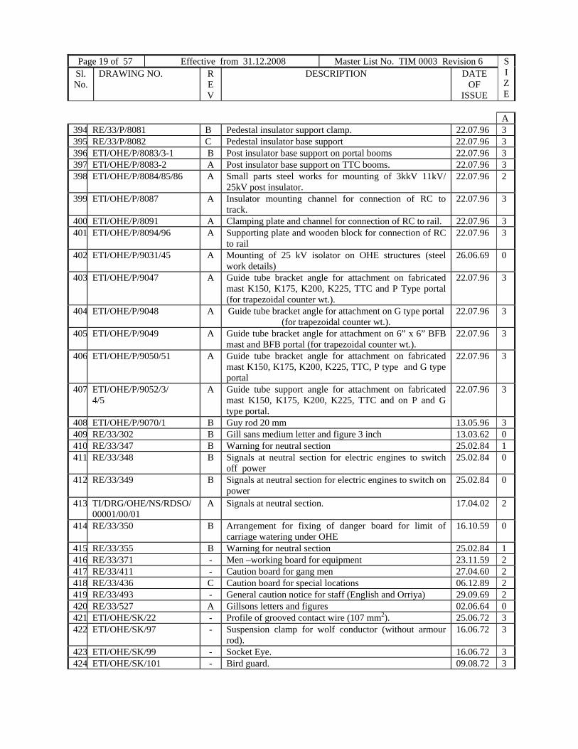
Page 19 of 57 Effective from 31.12.2008 Master List No. TIM 0003 Revision 6 SIZE
Sl. No.
DRAWING NO. REV
DESCRIPTION DATE OF
ISSUE
A 394 RE/33/P/8081 B Pedestal insulator support clamp. 22.07.96 3 395 RE/33/P/8082 C Pedestal insulator base support 22.07.96 3 396 ETI/OHE/P/8083/3-1 B Post insulator base support on portal booms 22.07.96 3 397 ETI/OHE/P/8083-2 A Post insulator base support on TTC booms. 22.07.96 3 398 ETI/OHE/P/8084/85/86 A Small parts steel works for mounting of 3kkV 11kV/
25kV post insulator. 22.07.96 2
399 ETI/OHE/P/8087 A Insulator mounting channel for connection of RC to track.
22.07.96 3
400 ETI/OHE/P/8091 A Clamping plate and channel for connection of RC to rail. 22.07.96 3 401 ETI/OHE/P/8094/96 A Supporting plate and wooden block for connection of RC
to rail 22.07.96 3
402 ETI/OHE/P/9031/45 A Mounting of 25 kV isolator on OHE structures (steel work details)
26.06.69 0
403 ETI/OHE/P/9047 A Guide tube bracket angle for attachment on fabricated mast K150, K175, K200, K225, TTC and P Type portal (for trapezoidal counter wt.).
22.07.96 3
404 ETI/OHE/P/9048 A Guide tube bracket angle for attachment on G type portal (for trapezoidal counter wt.).
22.07.96 3
405 ETI/OHE/P/9049 A Guide tube bracket angle for attachment on 6” x 6” BFB mast and BFB portal (for trapezoidal counter wt.).
22.07.96 3
406 ETI/OHE/P/9050/51 A Guide tube bracket angle for attachment on fabricated mast K150, K175, K200, K225, TTC, P type and G type portal
22.07.96 3
407 ETI/OHE/P/9052/3/ 4/5
A Guide tube support angle for attachment on fabricated mast K150, K175, K200, K225, TTC and on P and G type portal.
22.07.96 3
408 ETI/OHE/P/9070/1 B Guy rod 20 mm 13.05.96 3 409 RE/33/302 B Gill sans medium letter and figure 3 inch 13.03.62 0 410 RE/33/347 B Warning for neutral section 25.02.84 1 411 RE/33/348 B Signals at neutral section for electric engines to switch
off power 25.02.84 0
412 RE/33/349 B Signals at neutral section for electric engines to switch on power
25.02.84 0
413 TI/DRG/OHE/NS/RDSO/00001/00/01
A Signals at neutral section. 17.04.02 2
414 RE/33/350 B Arrangement for fixing of danger board for limit of carriage watering under OHE
16.10.59 0
415 RE/33/355 B Warning for neutral section 25.02.84 1 416 RE/33/371 - Men –working board for equipment 23.11.59 2 417 RE/33/411 - Caution board for gang men 27.04.60 2 418 RE/33/436 C Caution board for special locations 06.12.89 2 419 RE/33/493 - General caution notice for staff (English and Orriya) 29.09.69 2 420 RE/33/527 A Gillsons letters and figures 02.06.64 0 421 ETI/OHE/SK/22 - Profile of grooved contact wire (107 mm2). 25.06.72 3 422 ETI/OHE/SK/97 - Suspension clamp for wolf conductor (without armour
rod). 16.06.72 3
423 ETI/OHE/SK/99 - Socket Eye. 16.06.72 3 424 ETI/OHE/SK/101 - Bird guard. 09.08.72 3
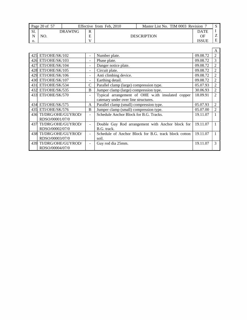
Page 20 of 57 Effective from Feb, 2010 Master List No. TIM 0003 Revision 7 SIZE
Sl. No.
DRAWING NO.
REV
DESCRIPTION
DATE OF
ISSUE
A 425 ETI/OHE/SK/102 - Number plate. 09.08.72 2 426 ETI/OHE/SK/103 - Phase plate. 09.08.72 3 427 ETI/OHE/SK/104 - Danger notice plate. 09.08.72 2 428 ETI/OHE/SK/105 - Circuit plate. 09.08.72 2 429 ETI/OHE/SK/106 - Anti climbing device. 09.08.72 2 430 ETI/OHE/SK/107 - Earthing detail. 09.08.72 2 431 ETI/OHE/SK/534 C Parallel clamp (large) compression type. 05.07.93 2 432 ETI/OHE/SK/535 B Jumper clamp (large) compression type. 30.06.93 2 433 ETI/OHE/SK/570 - Typical arrangement of OHE w.ith insulated copper
catenary under over line structures. 18.09.91 2
434 ETI/OHE/SK/575 A Parallel clamp (small) compression type. 05.07.93 2 435 ETI/OHE/SK/576 B Jumper clamp (small) compression type. 05.07.00 2 436 TI/DRG/OHE/GUYROD/
RDSO/00001/07/0 - Schedule Anchor Block for B.G. Tracks. 19.11.07 1
437 TI/DRG/OHE/GUYROD/RDSO/00002/07/0
- Double Guy Rod arrangement with Anchor block for B.G. track.
19.11.07 1
438 TI/DRG/OHE/GUYROD/RDSO/00003/07/0
- Schedule of Anchor Block for B.G. track block cotton soil.
19.11.07 1
439 TI/DRG/OHE/GUYROD/RDSO/00004/07/0
- Guy rod dia 25mm. 19.11.07 3
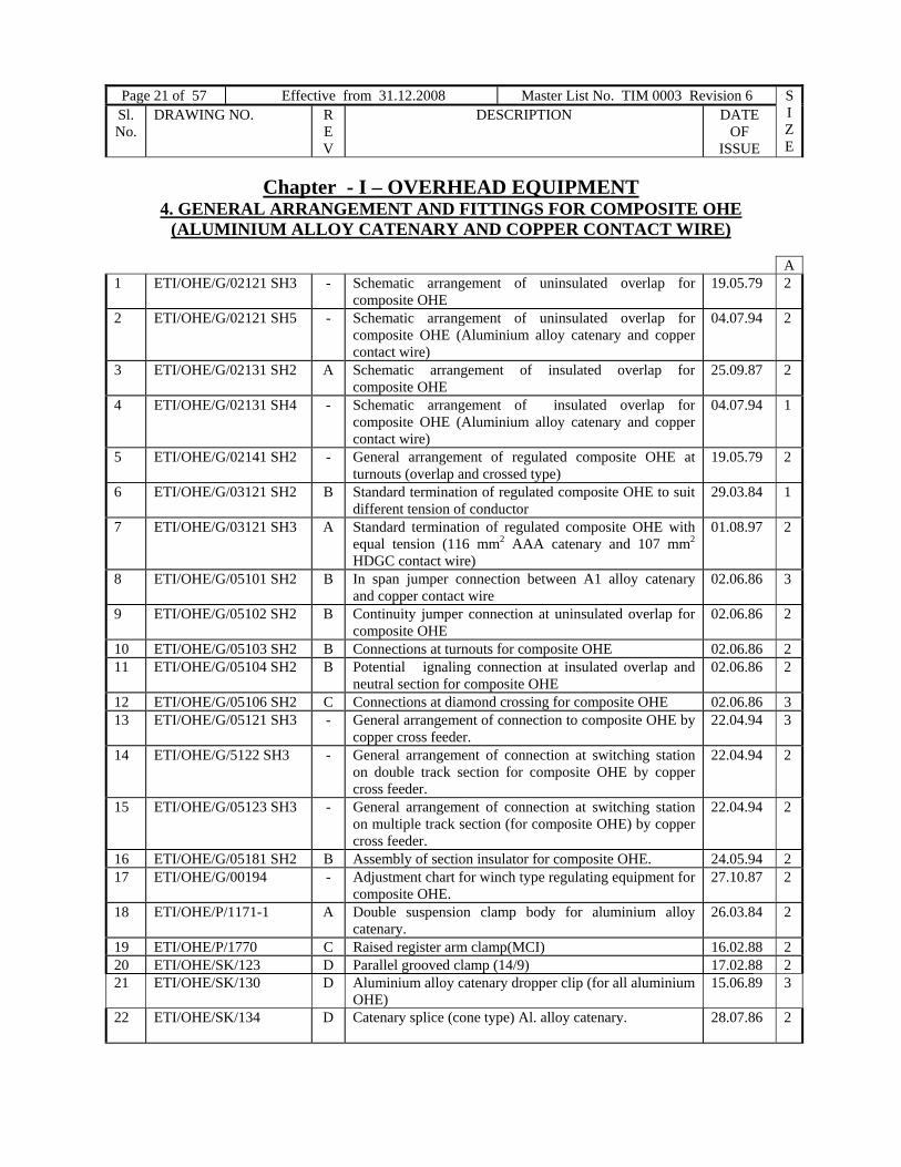
Page 21 of 57 Effective from 31.12.2008 Master List No. TIM 0003 Revision 6 SIZE
Sl. No.
DRAWING NO. REV
DESCRIPTION DATE OF
ISSUE
Chapter - I – OVERHEAD EQUIPMENT 4. GENERAL ARRANGEMENT AND FITTINGS FOR COMPOSITE OHE
(ALUMINIUM ALLOY CATENARY AND COPPER CONTACT WIRE)
A 1 ETI/OHE/G/02121 SH3 - Schematic arrangement of uninsulated overlap for
composite OHE 19.05.79 2
2 ETI/OHE/G/02121 SH5 - Schematic arrangement of uninsulated overlap for composite OHE (Aluminium alloy catenary and copper contact wire)
04.07.94 2
3 ETI/OHE/G/02131 SH2 A Schematic arrangement of insulated overlap for composite OHE
25.09.87 2
4 ETI/OHE/G/02131 SH4 - Schematic arrangement of insulated overlap for composite OHE (Aluminium alloy catenary and copper contact wire)
04.07.94 1
5 ETI/OHE/G/02141 SH2 - General arrangement of regulated composite OHE at turnouts (overlap and crossed type)
19.05.79 2
6 ETI/OHE/G/03121 SH2 B Standard termination of regulated composite OHE to suit different tension of conductor
29.03.84 1
7 ETI/OHE/G/03121 SH3 A Standard termination of regulated composite OHE with equal tension (116 mm2 AAA catenary and 107 mm2 HDGC contact wire)
01.08.97 2
8 ETI/OHE/G/05101 SH2 B In span jumper connection between A1 alloy catenary and copper contact wire
02.06.86 3
9 ETI/OHE/G/05102 SH2 B Continuity jumper connection at uninsulated overlap for composite OHE
02.06.86 2
10 ETI/OHE/G/05103 SH2 B Connections at turnouts for composite OHE 02.06.86 2 11 ETI/OHE/G/05104 SH2 B Potential ignaling connection at insulated overlap and
neutral section for composite OHE 02.06.86 2
12 ETI/OHE/G/05106 SH2 C Connections at diamond crossing for composite OHE 02.06.86 3 13 ETI/OHE/G/05121 SH3 - General arrangement of connection to composite OHE by
copper cross feeder. 22.04.94 3
14 ETI/OHE/G/5122 SH3 - General arrangement of connection at switching station on double track section for composite OHE by copper cross feeder.
22.04.94 2
15 ETI/OHE/G/05123 SH3 - General arrangement of connection at switching station on multiple track section (for composite OHE) by copper cross feeder.
22.04.94 2
16 ETI/OHE/G/05181 SH2 B Assembly of section insulator for composite OHE. 24.05.94 2 17 ETI/OHE/G/00194 - Adjustment chart for winch type regulating equipment for
composite OHE. 27.10.87 2
18 ETI/OHE/P/1171-1 A Double suspension clamp body for aluminium alloy catenary.
26.03.84 2
19 ETI/OHE/P/1770 C Raised register arm clamp(MCI) 16.02.88 2 20 ETI/OHE/SK/123 D Parallel grooved clamp (14/9) 17.02.88 2 21 ETI/OHE/SK/130 D Aluminium alloy catenary dropper clip (for all aluminium
OHE) 15.06.89 3
22 ETI/OHE/SK/134 D Catenary splice (cone type) Al. alloy catenary. 28.07.86 2
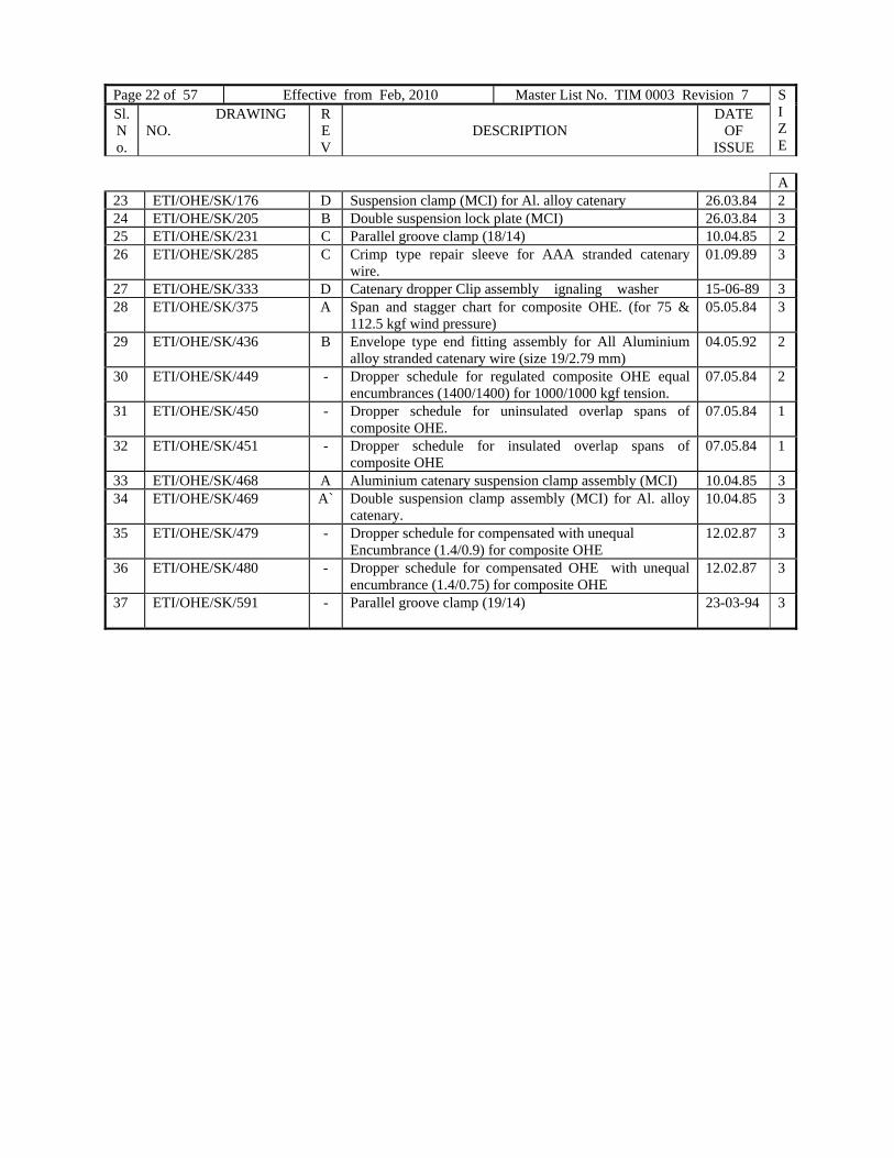
Page 22 of 57 Effective from Feb, 2010 Master List No. TIM 0003 Revision 7 SIZE
Sl. No.
DRAWING NO.
REV
DESCRIPTION
DATE OF
ISSUE
A23 ETI/OHE/SK/176 D Suspension clamp (MCI) for Al. alloy catenary 26.03.84 2 24 ETI/OHE/SK/205 B Double suspension lock plate (MCI) 26.03.84 3 25 ETI/OHE/SK/231 C Parallel groove clamp (18/14) 10.04.85 2 26 ETI/OHE/SK/285 C Crimp type repair sleeve for AAA stranded catenary
wire. 01.09.89 3
27 ETI/OHE/SK/333 D Catenary dropper Clip assembly ignaling washer 15-06-89 3 28 ETI/OHE/SK/375 A Span and stagger chart for composite OHE. (for 75 &
112.5 kgf wind pressure) 05.05.84 3
29 ETI/OHE/SK/436 B Envelope type end fitting assembly for All Aluminium alloy stranded catenary wire (size 19/2.79 mm)
04.05.92 2
30 ETI/OHE/SK/449 - Dropper schedule for regulated composite OHE equal encumbrances (1400/1400) for 1000/1000 kgf tension.
07.05.84 2
31 ETI/OHE/SK/450 - Dropper schedule for uninsulated overlap spans of composite OHE.
07.05.84 1
32 ETI/OHE/SK/451 - Dropper schedule for insulated overlap spans of composite OHE
07.05.84 1
33 ETI/OHE/SK/468 A Aluminium catenary suspension clamp assembly (MCI) 10.04.85 3 34 ETI/OHE/SK/469 A` Double suspension clamp assembly (MCI) for Al. alloy
catenary. 10.04.85 3
35 ETI/OHE/SK/479 - Dropper schedule for compensated with unequal Encumbrance (1.4/0.9) for composite OHE
12.02.87 3
36 ETI/OHE/SK/480 - Dropper schedule for compensated OHE with unequal encumbrance (1.4/0.75) for composite OHE
12.02.87 3
37 ETI/OHE/SK/591 - Parallel groove clamp (19/14) 23-03-94
3

Page 23 of 57 Effective from 31.12.2008 Master List No. TIM 0003 Revision 6 SIZE
Sl. No.
DRAWING NO. REV
DESCRIPTION DATE OF
ISSUE
5. GENERAL ARRANGEMENT FOR LOADING MECHANISM
A38 TI/DRG/OHE/COLLAP/
RDSO/0001/99/0 - Special bracket for collapsible OHE. 1999 2
39 TI/DRG/OHE/COLLAP/ RDSO/0002/99/0
- General arrangement of fixing the special bracket assembly & suspension of contact wire.
1999 1
40 TI/DRG/OHE/COLLAP/ RDSO/0003/99/0
- General arrangement of suspension of contact wire (S) from existing bracket assembly of tram-way OHE.
1999 0
41 TI/DRG/OHE/SWL/ RDSO/0004/08/0
- Motorised arrangement for collapsing the OHE. 2008 3
42 TI/DRG/OHE/COLLAP/ RDSO/0005/99/0
- General arrangement for collapsing the OHE. 1999 1
43 TI/DRG/OHE/COLLAP/ RDSO/0006/99/0
- General arrangement of fixing of conduit pipe on special bracket assembly & connection of wire rope.
1999 1
44 TI/DRG/OHE/SWL/ RDSO/0007/08/0
- General arrangement of Isolator connection to collapsible OHE.
2008 1
45 TI/DRG/OHE/COLLAP/ RDSO/0008/99/0
- Special stay arm insulator for collapsible OHE. 1999 3
46 TI/DRG/OHE/COLLAP/ RDSO/0009/99/0
- Special jumper clamp. 1999 3
47 TI/DRG/OHE/SWL/ RDSO/00010/08/0
- General arrangement (lay out plan) for the swiveling OHE.
2008 1

Page 24 of 57 Effective from Feb, 2010 Master List No. TIM 0003 Revision 7 SIZE
Sl. No.
DRAWING NO.
REV
DESCRIPTION
DATE OF
ISSUE
Chapter - II – POWER SUPPLY INSTALLATION
1. GENERAL ARRANGEMENT OF SUBSTATION, LAYOUT, SWITCHING STATION, BT, REMOTE CONTROL AND EARTHING ARRANGEMENT
A
1 ETI/PSI/003 C Typical location and schematic connection Diagram for a three interrupter switching station.
18.12. 84 0
2 ETI/PSI/004 F Typical General Arrangement of a three interrupter switching station
31.05.02 0
3 ETI/PSI/004-1 A Simplified typical general arrangement of a three interrupter switching station by eliminating double pole isolator.
16.03 98 0
4 ETI/PSI/OO5 F Typical location plan and general arrangement for sectioning and paralleling station.
31.05.02 0
5 ETI/PSI/005-1 A Simplified location plan and general arrangement for sectioning and paralleling station by eliminating DP isolator.
16.03.98 0
6 ETI/PSI/006 E Typical location plan and general arrangement for a feeding station
03.08.01 0
7 ETI/PSI/008 A Outrigger arrangement 08.02 80 1 8 ETI/PSI/009 A Typical location plan and general arrangement of a single
interrupter switching station. 27.02 75 1
9 ETI/PSI/009-1 - Simplified typical general arrangement of single interrupters switching station.
21.03. 94 1
10 ETI/PSI/0010 E Typical layout of remote control cubical at a switching station.
16.11. 88 2
11 ETI/PSI/0011 - Typical location plan and general arrangement of a single interrupter feeding station.
24.08.73 1
12 ETI/PSI/0012 - Layout and general arrangement of sectioning and paralleling station at Baranagar (Sealdah Divn E.Rly)
08.08.75 0
13 ETI/PSI/0016 A General arrangement and terminal connection of 25kv PT type-1 at switching station
10.07.81 2
14 ETI/PSI/0018 - Typical location plan and general arrangement for a feeding station.
19.03.84 0
15 ETI/PSI/0019 - Typical general arrangement of a four interrupter switching station.
21.03.84 0
16 ETI/PSI/011 C Typical general arrangement at a booster transformer station (without cross feeder), Type – I
07.09.80 1
17 ETI/PSI/011-I A Typical general arrangement at a booster transformer station (without cross feeder).
08.01.98 1
18 ETI/PSI/012 - Typical general arrangement at a booster transformer station (without cross feeder) Type-II
24.12.70 1
19 ETI/PSI/013 B Typical general arrangement at a booster transformer station (with 4- cross feeder), Type-III
30.05.81 1
20 ETI/PSI/013-I A Typical general arrangement at a booster transformer station (with cross feeder).
08.01.98 1
21 ETI/PSI/014 C Typical general arrangement at a booster transformer station (with SP isolator and 4- cross feeder). Type-IV
1

Page 25 of 57 Effective from 31.12.2008 Master List No. TIM 0003 Revision 6 SIZE
Sl. No.
DRAWING NO. REV
DESCRIPTION DATE OF
ISSUE
A 22 ETI/PSI/015 - Typical general arrangement at a booster transformer
station (with 4 cross feeder), Type-V 21.07.75 1
23 ETI./PSI/016 A Typical general arrangement at a booster transformer station (without cross feeder and 42 kV lightning arrester) – Type –VI
19.06.86 1
24 ETI/PSI/017 - 280 kVA Booster transformer station Type – VII 27.11.87 1 25 ETI/PSI/018 A General arrangement of 280 KVA Booster transformer
station (Type III) with four cross feeder. 18.03.88 1
26 ETI/PSI/019 - Typical general arrangement at a booster transformer station (for tramway type OHE)
12.04.94 1
27 TI/DRG/PSI/TSSLO/ RDSO/00001/01/0
- Typical layout of 132/27 kV traction substation (Type-I). 16.07.01 0
28 TI/DRG/PSI/TSSLO/ RDSO/00002/01/0
- Typical layout of 132/27 kV traction substation (Type – II).
16.01.02 0
29 TI/DRG/PSI/TSSLO/ RDSO/00003/02/0
- Typical layout of 132/27 kV traction substation (Type-III).
22.02.02 0
30 TI/DRG/PSI/TSSLO/ RDSO/00004/02/0
- Typical layout of 132/27 kV traction substation (Type-IV) with outgoing feeders and metering facilities.
17.05.02 0
31 TI/DRG/PSI/TSSLO/ RDSO/00005/02/0
- Typical layout of 132/27 kV traction substation (Type-V). 13.06.02 0
32 TI/DRG/PSI/TSSLO/ RDSO/00006/02/0
- Typical layout of 132/27 kV traction substation (Type-VI).
09.07.02 0
33 TI/DRG/PSI/TSSLO/ RDSO/00007/02/0
- Typical layout of 132/27 kV traction substation (Type – VII).
28.08.02 0
34 TI/DRG/PSI/TSSLO/ RDSO/00008/02/0
- Typical layout of 132/27 kV traction substation (Type-VIII).
27.11.02 0
35 TI/DRG/PSI/TSSLO/ RDSO/00009/02/0
A Typical layout of 132/27 kV traction substation with single transformer (Type IX).
16.12.02 0
36 TI/DRG/PSI/TSSLO/ RDSO/00010/02/0
G Typical layout of 132/25 kV traction substation with 132 kV switching station (Type – X).
30.12.02 0
37 ETI/PSI/022-I B Typical layout of 132/25 kV traction substation (Type-II).
23.03.94 0
38
TI/DRG/PSI/CPROOM/RDSO/00001/01/0
- Typical layout of control room at traction substation. 20.05.01 2
39 ETI/PSI/0212-1 - Typical return current connection to buried rail at 132/25 kV traction substation
26.10.98 1
40 ETI/PSI/0213 A General arrangement for 132 kV Railway switching station at Aligarh.
20.03.74 2
41
ETI/PSI/0215 B Schematic layouts for different types of 132/25 kV traction substation.
21.09.83 1
42 ETI/PSI/0216 B Arrangement for typical outdoor illumination of 132/25 kV traction substation.
12.08.83 1
43 ETI/PSI/0217 B Typical arrangement of connection for 25 kV potential transformer with 36 mm O/D aluminium Bus bar.
22.12.79 3
44 ETI/PSI/0225 C Typical general arrangement of earth screen wire termination at traction substation.
July 00 1

Page 26 of 57 Effective from Feb, 2010 Master List No. TIM 0003 Revision 7 SIZE
Sl. No.
DRAWING NO.
REV
DESCRIPTION
DATE OF
ISSUE
A
45 ETI/PSI/0226 B Typical terminal arrangement for strung bus ‘SPIDER’ (AAC) conductor at traction substation.
18.03.94 2
46 ETI/PSI/0226-I A Typical terminal arrangement for strung bus at traction substation with ZEBRA conductor.
18.03.94 3
47 ETI/PSI/0227 A General arrangement and terminal connection for 25 kV PT (Type-II) at traction substation.
10.07.81 2
48 ETI/PSI/0227-I - General arrangement and terminal connection for 25 kV PT type-II (protection type) at 220 kV traction substation.
10.06.87. 2
49 ETI/PSI/0233 - Typical layout of 132/25kv traction substation showing 25kv feeder for yard / electric loco shed supply.
21.03.84 0
50 ETI/PSI/0235 A Typical layout of 132/25kv Traction substation(with three transformer) Type-1
09.03.90
0
51 ETI/PSI/0237 - Typical layout of 132/25kv Traction substation (with three transformers) Type-111.
30.05.86 0
52 ETI/PSI/0239 - Typical layout of 132/25kv Traction substation (with three transformers) Type –v
05.06.86 0
53 ETI/PSI/0240 - Typical layout of 220/25 kV traction substation Type-I 10.06.87 0 54 ETI/PSI/0240-1 - Typical layout of 22o/27kV traction substation type-1 0 55 ETI/PSI/0242 A Typical return current connection to buried rail at
220/25Kv traction substation. 18.11.87 1
56 ETI/PSI/0243 A Typical termination arrangement for strung bus (ZEBRA,ACSR) conductor at 220 kV traction substation
18.03.94 3
57 ETI/PSI/0244 - Typical general arrangement of earth screen wire termination at 220Kv traction substation
10.06.87 2
58 ETI/PSI/032 D 25kv drop out fuse assembly. 28.01.86 3 59 ETI/PSI/035 B 4 Pole 5 way rotary switches for colour light signaling
and emergency load. 13.09.91
3
60 TI/DRG/PSI/AT/ RDSO/00001/02/1
- Arrangement of Mounting 25Kv/240V, 50 kV LT Supply transformer.
18.01.05 2
61 ETI/PSI/037 C Structural details for LT supply transformer T-150 30.09.86 0 62 ETI/PSI/038 C 25Kv dropout fuses switch details. 29.08.89 1 63 ETI/PSI/039 B Operating pole for 25Kv dropout fuse switch. 28.01.86 2 64 ETI/PSI/0310 - LV Box assembly for LT supplies transformer stations. 08.05.81 1 65 ETI/PSI/0312 B Mounting Arrangement of 100 KVA, 25 kV/240 V LT
supply transformer at traction substation. 22.09.89. 2
66 ETI/PSI/101 B Structural assembly for a feeding station. 15.02.85 1 67 ETI/PSI/102 B Structural assembly for a sectioning and paralleling
station. 15.02.85 1
68 ETI/PSI/103 B Structural assembly for a three interrupter switching station.
15.02.85 1
69 ETI/PSI/104 E Typical fencing and anticlimbing arrangement at switching station.
18.12.84 1
70 ETI/PSI/105 - Structural assembly for feeding station (for five cross feeders)
21.03.84 0
71 ETI/PSI/106 A Structural assembly for a four interrupter switching station
21.03.84 1
72 ETI/PSI/111 A Structural assembly for standard booster transformer station (without cross feeder – Type-I)
11.04.75 2
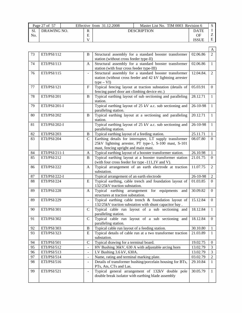
Page 27 of 57 Effective from 31.12.2008 Master List No. TIM 0003 Revision 6 SIZE
Sl. No.
DRAWING NO. REV
DESCRIPTION DATE OF
ISSUE
A 73 ETI/PSI/112 B Structural assembly for a standard booster transformer
station (without cross feeder type-II) 02.06.86 2
74 ETI/PSI/113 A Structural assembly for a standard booster transformer station (with four cross feeder type-III)
02.06.86 1
76 ETI/PSI/115 - Structural assembly for a standard booster transformer station (without cross feeder and 42 kV lightning arrester type – VI)
12.04.84. 2
77 ETI/PSI/121 F Typical fencing layout at traction substation (details of fencing panel door ant climbing device etc.)
05.03.91 0
78 ETI/PSI/201 B Typical earthing layout of sub sectioning and paralleling station.
28.12.71 1
79 ETI/PSI/201-I Typical earthing layout of 25 kV a.c. sub sectioning and paralleling station.
26-10-98 1
80 ETI/PSI/202 B Typical earthing layout at a sectioning and paralleling station.
20.12.71 1
81 ETI/PSI/202-I Typical earthing layout of 25 kV a.c. sub sectioning and paralleling station.
26-10-98 1
82 ETI/PSI/203 B Typical earthing layout of a feeding station. 25.11.71 1 83 ETI/PSI/204 C Earthing details for interrupter, LT supply transformer
25kV lightning arrester, PT type-1, S-100 mast, S-101 mast, fencing upright and main mast.
08.07.80 0
84 ETI/PSI/211-1 A Typical earthing layout of a booster transformer station. 26.10.98 1 85 ETI/PSI/212 B Typical earthing layout at a booster transformer station
(with four cross feeder for type -111,1V and V). 21.01.75 0
86 ETI/PSI/222 A Typical arrangement of an earth electrode at traction substation.
11.07.75 2
87 ETI/PSI/222-I Typical arrangement of an earth electrode 26-10-98 2 88 ETI/PSI/224 E Typical earthing, cable trench and foundation layout of
132/25kV traction substation. 01.03.85 0
89 ETI/PSI/228 A Typical earthing arrangement for equipments and structures at traction substation.
30.09.82 0
89 ETI/PSI/229 - Typical earthing cable trench & foundation layout of 132/25kV traction substation with shunt capacitor bay .
15.12.84 0
90 ETI/PSI/301 C Typical cable run layout of a sub sectioning and paralleling station.
18.12.84 1
91 ETI/PSI/302 C Typical cable run layout of a sub sectioning and paralleling station.
18.12.84 0
92 ETI/PSI/303 B Typical cable run layout of a feeding station. 30.10.80 1 93 ETI/PSI/323 E Typical details of cable run at a two transformer traction
substation. 21.03.89 1
94 ETI/PSI/501 C Typical drawing for a terminal board. 19.02.75 0 95 ETI/PSI/512 - HV Bushing 36kV, 630 A with adjustable arcing horn 13.02.79 3 96 ETI/PSI/513 - LV Bushing 3.6 kV, 630A. 13.02.79 3 97 ETI/PSI/514 - Name, rating and terminal marking plate. 03.02.79 2 98 ETI/PSI/516 - Details of transformer bushing/porcelain housing for BTs,
PTs, Ats, CTs and Las. 29.10.84 1
99 ETI/PSI/521 - Typical general arrangement of 132kV double pole
double break isolator with earthing blade assembly 30.05.79 1

Page 28 of 57 Effective from Feb, 2010 Master List No. TIM 0003 Revision 7 SIZE
Sl. No.
DRAWING NO.
REV
DESCRIPTION
DATE OF
ISSUE
A 100 ETI/PSI/5211 A Cast ell type mechanical integral / interlock for 132kV
isolator 09.07.81 3
101 ETI/PSI/5212 B Scheme of locking /interlocking arrangement of 132kV
isolator at traction substation. 17.03.87 0
102 ETI/PSI/5213 A General arrangement of 25Kv outdoor type CT. 04.02.81 2 103 ETI/PSI/5214 B Scheme of interlocking arrangement for 25 kV circuit
breakers at traction substations. 03.10.86 2
104 ETI/PSI/5215 - Scheme of interlocking arrangement for 25 kV circuit breaker at three transformer substation.
02.06.86 2
105 ETI/PSI/611 A Existing and proposed arrangement for provision of rail links between RC and rail.
11.12.85 2
106 ETI/PSI/623 B Typical control desk. 12.08.80 3 107 ETI/PSI/624 A Schematic diagram of 132/25 kV traction substation
showing scheme of interlocking of circuit breaker and isolators.
24.02.84 3
108 ETI/PSI/628 A Typical layout of zonal repair shop for PSI equipment. 17.06.87 0 109 ETI/PSI/642 A Miniature lamp 25V, 1W for use in discrepancy switch on
the mimic diagram board in remote control center. 16.05.85 3
110 ETI/PSI/651 - Layout of 25 kV/415V emergency power supply equipment.
21.04.82 0
111 ETI/PSI/704-I - Traction power supply arrangement for yard/electric loco shed
17.04.90 1
112 ETI/PSI/709 A General scheme of supply for 25 kV ac traction system in Mumbai area after conversion from dc to ac.
10.10.01 2
113 ETI/PSI/708 - Typical earthing arrangement of an auxiliary transformer. 31.01.94 3
114 ETI/PSI/SK/344 - Castel and bolted type lock with common key for 25 kV ac single pole CB/interrupters.
18.03.94 4
116 TI/GRG/PSI/MOTISO/ 00002/06/0
- Typical assembly of 25kV single and double pole Motorized Isolator.
18.08.06 1
117 TI/DRG/PSI/ INTERLOCK/RDSO/ 00001/06/0
- Scheme of interlocking arrangement of 25 kV circuit breaker at traction substation for MRVC.
07.08.06 3

Page 29 of 57 Effective from 31.12.2008 Master List No. TIM 0003 Revision 6 SIZE
Sl. No.
DRAWING NO. REV
DESCRIPTION DATE OF
ISSUE
Chapter - II – POWER SUPPLY INSTALLATION
2) GENERAL ARRANGE MENT OF SUBSTATION LAYOUT , SWITCHING
STATION , BT, REMOTE CONTROL AND EARTHING ARRANGEMENT FOR 2 X 25KV `AT’ SYSTEM.
A1 ETI/PSI/AT/0201 B Typical layout of 220/2x 25 kV traction substations with
scot-connected transformers (for double line section). 18.09.91 0
2 ETI/PSI/AT/0202 - Typical layout of 132/2x25 traction sub-station with three single phase transformers for single line section (V connection type).
27.10.89 0
3 ETI/PSI/AT/0203 - Typical layout of 132/2x25 kV traction sub-station with single phase transformer (for single line section)
27.10.89 0
4 ETI/PSI/AT/00101 A Typical layout for sub-sectioning and paralleling post (SSP) in 2x25 kV ‘AT’ system (on double track section).
18.09.91 1
5 ETI/PSI/AT/00102 C Typical layout for sectioning and paralleling post (SP) in 2x25 kV ‘AT’ system (on double traction section)
17.02.92 1
6 ETI/PSI/AT/00103 A Typical layout for sub-sectioning post in 2x25 kV ‘AT’ system (on single track section)
18.09.91 1
7 ETI/PSI/AT/00104 B Typical layout for sectioning post in 2x25 kV ‘AT’ system ( on single track section).
18.09.91 1
8 ETI/PSI/AT/00105 - Typical layout for a Auto transformer post (on double track section)
23.10.90. 1

Page 30 of 57 Effective from Feb, 2010 Master List No. TIM 0003 Revision 7 SIZE
Sl. No.
DRAWING NO.
REV
DESCRIPTION
DATE OF
ISSUE
Chapter - II – POWER SUPPLY INSTALLATION 3. SHUNT CAPACITORS AND PROTECTION FOR 25 Kv ac TRACTION
SYSTEM A
1
ETI/PSI/024-I - Typical schematic diagram of protection for double transformer traction sub-station.
22.04.94.
1
2 ETI/PSI/0223 E Typical layout for 25 kV shunt capacitor unit to be installed at 132/25kV traction substation type-I
23.12.97 1
3 ETI/PSI/0228-I - Typical schematic diagram of protection for single transformer traction substation
22.04.94 1
4 ETI/PSI/0231-I A High speed auto-reclosing scheme for feeder circuit breaker at 25 kV traction substation.
18.03.94. 3
5 ETI/PSI/0232 - Schematic diagram of remote controlled flasher arrangement at TSS and OHE masts opposite feeding post.
25.07.83. 1
6 ETI/PSI/034 A Schematic power supply diagram for colour light signaling and other loads from 10KVA, 25 kV/240 V LT supply transformer.
04.05.73. 3
7 ETI/PSI/035-4 - Out line general arrangement for control & distribution panel for colour light ignaling with automatic change over facility (3 sources) for 25 kV ac traction system.
21.03.07 3
8 ETI/PSI/325 - Typical details of cable run at a two transformer traction substation with shunt capacitor.
15.12.84 1
9 ETI/PSI/326 - Typical details of cable run at a two transformer traction substation with shunt capacitor.(220 kV)
10.06.87 1
10 ETI/PSI/642 A Miniature lamp 25 kV, 1W for use in discrepancy switch on the mimic diagram board in remote control centre.
16.05.85 3
11 ETI/PSI/644 C Schematic interconnection diagram for remote control of power gear and supervision of equipment at traction substation.
21.08.89. 1
12 ETI/PSI/645 C Schematic interconnection diagram for remote control of power gear and supervision of equipments at controlled station. (SP and SSP).
21.08.89. 2
13 ETI/PSI/646 A Miniature lamp 30 V, 40 Ma for use in discrepancy switch of telefonbau make on the mimic diagram board in remote control center.
16.05.81. 3
14 ETI/PSI/647 - Control and relay panel for ac traction substation. 20.07.84. 2 15 ETI/PSI/648 A Typical layout of remote control center. 30.04.85. 1 16 ETI/PSI/652 - Typical layout of remote control center for computer
based SCADA system. 06.09.90 1
17 ETI/PSI/SK/343 - Typical schematic protection arrangement of shunt capacitor bank at traction substation.
17.02.94. 4
18 ETI/PSI/702-1 D General Scheme of supply for 25 kV, 50 Hz, 1 phases traction system.
18.12.97 2
19 TI/DRG/PSI/RCC/ 00001/07/0
- Fixing arrangement of mast Anchor fitting for Antifouling device in three pulleys (MOD) ATD.

Page 31 of 57 Effective from 31.12.2008 Master List No. TIM 0003 Revision 6 SIZE
Sl. No.
DRAWING NO. REV
DESCRIPTION DATE OF
ISSUE
Chapter - II – POWER SUPPLY INSTALLATION
4. PROTECTION FOR 2 X 25 kV ‘ AT’ SYSTEM
A 1. ETI/PSI/AT/0204 SH-1/4 B Protection scheme for scot connected transformer
(2x 25 kV system). 29.09.93. 4
2. ETI/PSI/AT/0204 SH-2/4 B Differential protection for scot connected transformer (2 x 25 kV system).
29.09.93. 4
3. ETI/PSI/AT/0204 SH-3/4 B Protection scheme for single-phase transformer (2x 25 kV system).
29.09.93. 4
4. ETI/PSI/AT/0204 SH-4/4 B Protection scheme for 2x 25 kV OHE AT TSS. 29.09.93 4

Page 32 of 57 Effective from Feb, 2010 Master List No. TIM 0003 Revision 7 SIZE
Sl. No.
DRAWING NO.
REV
DESCRIPTION
DATE OF
ISSUE
Chapter - II – POWER SUPPLY INSTALLATION
5. COMPONENTS AND FITTINGS
A
1. ETI/PSI/P/6480 C 36 mm Aluminium bus terminal. 10.09.86. 3 2. ETI/PSI/P/6480-1 A Expansion type terminal connector suitable for 36 mm
aluminum tubular bus bar to suit 25 kV isolator terminal pad.
7.08.86. 3
3. ETI/PSI/P/6480-2 - 50 mm Aluminium bus terminal. 04.06.87 3 4. ETI/PSI/P/6480-3 A Expansion type terminal connector suitable for 50 mm
aluminum tubular bus bar to suit 25 kV isolator terminal pad.
26.04.88. 3
5. ETI/PSI/P/6481 C 36 mm Aluminium bus terminal. 10.09.86. 3 6. ETI/PSI/P/6482 C Clamping piece. 10.09.86 3 7. ETI/PSI/P/6482-1 C Clamping piece for 36 mm flexible bus splice. 14.11.86 3 8. ETI/PSI/P/6490 C 36 mm Aluminium bus splice. 10.09.86 3 9. ETI/PSI/P/6490-1. - 50 mm Aluminium bus splice. 04.06.87. 3 10. ETI/PSI/P/6491. B 36 mm Aluminium bus splice body. 07.08.86 3 11. ETI/PSI/P/6500. C 36 mm Aluminium bus Tee connector. 14.12.88 3 12. ETI/PSI/P.6500-1. - 50 mm Aluminium bus tee connector. 04.06.87 3 13. ETI/PSI/P/6501 B 36 mm Aluminium bus tee connector body. 10.09.86. 3 14. ETI/PSI/P/6510 D 36 mm Aluminium tee terminal. 10.09.86 3 15. ETI/PSI/P/6510-1 - 50 mm Aluminium tee terminal. 10.06.87 3 16. ETI/PSI/P/6511 C 36 mm Aluminium tee terminal body. 07.08.86 3 17. ETI/PSI/P/6520 B 36/15 mm taps connector. 07.08.86. 3 18. ETI/PSI/P/6521. B 36/15 mm taps connector body. 07.08.86. 3 19. ETI/PSI/P/6523 B Clamping piece (small). 10.09.86. 3 20. ETI/PSI/P/6530 C 36/20 mm terminal connector. 07.08.86. 3 21. ETI/PSI/P/6531 D 36/20 mm terminal connector body. 13.01.87 3 22. ETI/PSI/P/6540 A Terminal connector for 25 kV PT with 36 mm
Aluminium bus bar. 07.02.79 3
23. ETI/PSI/P/6541 B 36 mm Aluminium bus bar connector body. 3 24. ETI/PSI/P/6550 B 36 mm Aluminium flexible bus splice. 13.11.86 2 25. ETI/PSI/P/6550-1 - 50 mm Aluminium flexible bus splice. 22.05.87 2 26. ETI/PSI/P/6551 C 36 mm Aluminium bus junction connector body. 13.11.86 3 27. ETI/PSI/P/6552 C 36 mm Aluminium bus double sliding body. 13.11.86 2 28. ETI/PSI/P/6553 C Flexible joint. 13.11.86 2 29. ETI/PSI/P/6560 B 36 mm Aluminium bus splice cum tee connector. 10.09.86 3 30. ETI/PSI/P/6561 B 36 mm Aluminium bus splice cum tee connector body. 10.09.86. 2 31. ETI/PSI/P/6570 F Flexible connector for 25 kV circuit breaker, 25 kV
interrupter and 25 kV side of 13.5/20 MVA traction transformer.
18.11.86. 3
32. ETI/PSI/P/6580 B 36/20 mm taps connector. 07.08.86 3 33. ETI/PSI/P/6580-1 - 50/20 mm taps connector. 04.06.87. 3 34. ETI/PSI/P/6581 B 36/20 mm taps connector body. 07.08.86 3 35. ETI/PSI/P/6590 B 20 mm Aluminium bus bar tee connector 07.08.86 3
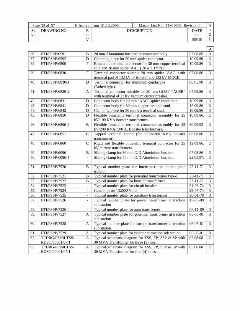
Page 33 of 57 Effective from 31.12.2008 Master List No. TIM 0003 Revision 6 SIZE
Sl. No.
DRAWING NO. REV
DESCRIPTION DATE OF
ISSUE
A 36. ETI/PSI/P/6591 B 20 mm Aluminium bus bar tee connector body. 07.08.86. 3 37. ETI/PSI/P/6592 D Clamping piece for 20 mm spider connector. 10.09.86. 3 38. ETI/PSI/P/6800 F Bimetallic terminal connector for 30 mm copper terminal
stud and 20 mm spider AAC (RIGID TYPE). 10.09.86 3
39. ETI/PSI/P/6830 F Terminal connector suitable 20 mm spider `AAC’ with terminal pad of 132 kV of isolator and 132 kV MOCB.
07.08.86 3
40. ETI/PSI/P/6830-1 D Terminal connector for aluminum conductors (Bolted type).
08.05.90 3
41. ETI/PSI/P/6830-2 A Terminal connector suitable for 20 mm GOAT “ACSR” with terminal of 22 kV vacuum circuit breaker.
07.08.86 3
42. ETI/PSI/P/6831 D Connector body for 20 mm “AAC” spider conductor. 10.09.86. 3 43. ETI/PSI/P/6841 D Connector body for 30 mm copper terminal stud. 12.09.86 3 44. ETI/PSI/P/6842 D Clamping piece for 30 mm dia terminal stud. 10.09.86 3 45. ETI/PSI/P/6850 D Flexible bimetallic terminal connector assembly for 25
kV/100 KVA booster transformer. 10.09.86. 2
46. ETI/PSI/P/6850-2 B Flexible bimetallic terminal connector assembly for 25 kV/280 KVA, 500 A. Booster transformers.
30.09.92 3
47. ETI/PSI/P/6851 C Tapped terminal clamp (for 25Kv/100 KVA booster transformer).
06.08.86 3
48. ETI/PSI/P/6860 C Rigid and flexible bimetallic terminal connector for 25 kV current transformers.
12.09.86. 2
49. ETI/PSI/P/6096 B Sliding clamp for 36 mm O/D Aluminium bus bar. 07.08.86 3 50. ETI/PSI/P/6096-1 - Sliding clamp for 50 mm O/D Aluminium bus bar. 22.05.87.
3
51. ETI/PSI/P/7520 B Typical number plate for interrupter and double pole isolator
23-11-71 3
52. ETI/PSI/P/7521 B Typical number plate for potential transformer type-I 23-11-71 3 53. ETI/PSI/P/7522 B Typical number plate for booster transformer 23-11-71 3 54. ETI/PSI/P/7523 - Typical number plate for circuit breaker 04-03-74 3 55. ETI/PSI/P/7524 - Caution plate 132000 Volts 29-05-74 3 56. ETI/PSI/P/7525 - Typical number plate for auxiliary transformer 20-01-78 3 57. ETI/PSI/P/7526 - Typical number plate for power transformer at traction
sub station 15-05-80 3
58. ETI/PSI/P/7526-I - Typical number plate for auto transformer 08-11-89 3 59. ETI/PSI/P/7527 A Typical number plate for potential transformer at traction
sub station 06-05-81 3
60. ETI/PSI/P/7528 A Typical number plate for current transformer at traction sub station
06-05-81 3
61. ETI/PSI/P/7529 A Typical number plate for isolator at traction sub station 06-05-81 3 62. TI/DRG/PSI/3LTSS/
RDSO/00001/07/1 A Typical schematic diagram for TSS, FP, SSP & SP with
30 MVA Transformer for three (3) line. 05.08.08 2
63. TI/DRG/PSI/4LTSS/ RDSO/00001/07/1
A Typical schematic diagram for TSS, FP, SSP & SP with 30 MVA Transformer for four (4) lines.
05.08.08 2

Page 34 of 57 Effective from Feb, 2010 Master List No. TIM 0003 Revision 7 SIZE
Sl. No.
DRAWING NO.
REV
DESCRIPTION
DATE OF
ISSUE
Chapter - II – POWER SUPPLY INSTALLATION
6. HIGHER CAPACITY CONNECTORS FOR 220 Kv AND 25 Kv (50 mm O/D ALUMINIUM BUS BAR) SYSTEM.
A1. ETI/PSI/P/11010 C Bimetallic terminal connector to suit ‘ZEBRA’ ACSR
conductor and 30 dia copper stud of CT/CB/traction power transformer.
12.09.91 2
2 ETI/PSI/P/11020 E Details of expansion bimetallic terminal connectors suitable for 50 dia Aluminum tubular bus bar to 60 dia copper copper stud of 25 kV CT.
04.10.90 2
3 ETI/PSI/P/11030 C Bimetallic terminal connector to suit “ZEBRA” (28.58 dia) ACSR conductor and aluminum/copper pad of isolator/CT/BT (for 220 kV system).
03.02.89 2
4 ETI/PSI/P/11040 C Tee connector to suit” ZEBRA” (28.58 dia) ACSR conductor on both ways for (220 kV system).
03.02.89 2
5 ETI/PSI/P/11050 C Rigid connector on S.I. to suit “ZEBRA” (28.58 Dia) ACSR conductor (for 220 kV system).
17.02.89 2
6 ETI/PSI/P/11060 E Details of expansion type terminal connector to suit 50 dia Aluminum tubular bus bar to terminal pad of 25 kV CT/isolator/CB and interrupter.
10.04.90 2
7 ETI/PSI/P/11070 B Details of rigid type bimetallic terminal connector suitable for 50 dia aluminum tubular bus bar to suit 30 dia copper stud of 25 kV current transformers.
03.02.89 2
8 ETI/PSI/P/11080 B Details of rigid type terminal connector suitable for 50 dia aluminum tubular bus bar to suit 60 dia copper stud of 25 kV current transformers.
03.02.89 2
9 ETI/PSI/P/11090 C
Rigid type bimetallic connector suitable for 50 dia aluminum tubular bus bar to terminal pad of 25 kV isolator/CT.
03.02.89 2
10 ETI/PSI/P/11100 E Details of expansion type bimetallic terminal connector suitable for 50 dia aluminum tubular bus bar to suit 30 dia copper studs of 25 kV CT/BT/Traction power transformer.
04.10.90 2
11 ETI/PSI/P/11110 C Rigid through connector to suit 50 dia aluminum tubular bus bar and “SPIDER” AAC conductor for 25 kV PT type II.
04.10.90 2
12 ETI/PSI/P/11120 C Detail of rigid terminal connector suitable for 20 dia aluminum conductor to terminal pad of 25 kV PT type-I and type-II.
03.02.89 2
13 ETI/PSI/P/11130 B Inter connector suitable for 50 O/D aluminum tube and “SPIDER” AAC conductor (for 25 kV PT type-I).
03.02.89 2
14 ETI/PSI/P/11140 B Tee connector to suit 50 O/D aluminum tube and “SPIDER” AAC conductor (for 25 kV systems).
03.02.89 2

Page 35 of 57 Effective from 31.12.2008 Master List No. TIM 0003 Revision 6 SIZE
Sl. No.
DRAWING NO. REV
DESCRIPTION DATE OF
ISSUE
A 16 ETI/PSI/P/11160 B Tee connector to suit 50 O/D aluminum tube to 36 O/D
aluminum tube (for 25 kV systems). 03.02.89 2
17 ETI/PSI/P/11170 C Tee connector to suit 50 O/D aluminum bus bar and 15 O/D cadmium catenary (for 25 kV systems).
03.02.89
2
18 ETI/PSI/P/11180 B Rigid bus splices connector to 50 O/D aluminum tube on both ways (for 25 kV systems).
03.02.89 2
19 ETI/PSI/P/11190 C Sliding clamp for 50 mm O/D aluminum bus bar (For 25 kV systems).
03.02.89 2
20 ETI/PSI/P/11200 C Rigid type connector on S.I. to suit 50 O/D aluminum bus bar (for 25 Kv systems).
17.02.89 2
21 ETI/PSI/P/11210 D Expansion bus coupler on S.I. to 50 O/D aluminum tube (for 25 kV systems).
04.10.90 2
22 ETI/PSI/P/11220 D Expansion type terminal connector for 25 kV, 60 mm dia. Terminal stud for traction power transformer.
12.09.91 2
23 ETI/PSI/P/11230 C Expansion type terminal connector for 25 kV, 30 mm dia. Terminal for traction power transformer.
04.10.90 2
24 ETI/PSI/P/11240 C Tee connector to suit 36 mm O/D aluminum bus bar to 50 mm O/D aluminum bus bar.
04.10.90 2

Page 36 of 57 Effective from Feb, 2010 Master List No. TIM 0003 Revision 7 SIZE
Sl. No.
DRAWING NO.
REV
DESCRIPTION
DATE OF
ISSUE
Chapter - III – CIVIL
1. OHE MAST (STEEL)
A
1. ETI/C/0018-2 D 9.5 m standard traction mast (fabricated ‘K’ series) 14.08.91 1 2. ETI/C/0071 E 9.5 m standard traction mast (fabricated with batten
plates) ‘B’ series. 14.08.91 1
3. ETI/C/0072 SH1 - Emergency OHE mast on sleeper General arrangement 23.11.82 2 4. ETI/C/0072 SH2 A Emergency OHE mast on sleeper Detail of top
middle and bottom parts 06.03.91 1
5. ETI/C/0072 SH3 B Emergency OHE mast on sleeper (details of base connection)
05.03.91
1
6. ETI/C/0073 A Dimension of bolts, nuts and lock nuts for 25kV ac traction.
08.04.93 2
7. ETI/C/0074 A 16 Dia J Bolts for 25 KVA ac traction 02.02.89 3 8. ETI/C/0075 - Washers and split pin for 25 kV ac traction 07.10.87 2 9. ETI/C/0078 SH1 - 9.5 m long standard traction masts (fabricated with
batten plate) ‘TM’ series. 29.09.93 2
10. ETI/C/0078 SH2 - 9.5 m long standard traction masts (fabricated with batten plate) ‘TM’ series (weight schedule)
29.09.93 1
11. Ti/DRG/CIV/B-MAST / RDSO/00001/08/0
- 10.850 m. long standard traction mast (Fabricated with batten plates) ``B” Series
08.04.08 1

Page 37 of 57 Effective from 31.12.2008 Master List No. TIM 0003 Revision 6 SIZE
Sl. No.
DRAWING NO. REV
DESCRIPTION DATE OF
ISSUE
Chapter - III - CIVIL
2) OHE PORTALS, TTC, DROP ARMS AND SPS
A 1. ETI /C/0004 SH 1 A ‘N’ type portal short upright. NUS1 -9.945 m long for RL
platform 04.03.91 1
2. ETI/C/0004 SH2 C ‘N’ type portal short upright. NUS2 –9.490 m long for LL platform
04.03.91 1
3. ETI/C/0004 SH3 A ‘N’ type portal short upright. NUS3 –9.185 m long for HL platform
04.03.91 1
4. ETI/C/0004 SH4 A ‘N’ type portal short upright. NUS4 –8.880 m long for Goods platform
04.03.91 1
5. ETI /C/0006/68 A Black weight of ‘G’ type portal 18.12.74 26. ETI/C/0008 SH1 A Standard ‘N’ type portal (rod laced), General arrangement 16.08.88 17. ETI/C/0008 SH2 B Standard ‘N’ type portal (rod laced) ,Details of upright 04.03.91 18. ETI/C/0008 SH3 C Standard ‘N’ type portal (rod laced), Details of end piece of
top boom (length 5380 mm) 04.03.91 1
9. ETI/C/0008 SH3A B Standard ‘N’ type portal (rod laced) , Details of end piece of top boom (length 5880 mm)
04.03.91 1
10.ETI/C/0008 SH4 B Standard ‘N’ type portal (rod laced), Details of central piece of top boom (length 1.5,3.0,4.5, 6.0,7.5&9.0m)
04.03.91 0
11.ETI/C/0008 SH5 C Standard ‘N’ type portal (rod laced) , Details of splicing and cover angles
04.03.91 2
12.ETI/C/0008 SH6 A Standard ‘N’ type portal (rod laced) , Details of knee bracing
04.03.91 2
13.ETI/C/0009/69 SH1 B Two track cantilever structure General arrangement 01.05.89 214.ETI/C/0009/69 SH2 C Two track cantilever structure Details of upright 04.03.91 115.ETI/C/0009/69 SH3 B Two track cantilever structure Details of knee plate 04.03.91 216.ETI/C/0009/69 SH4 C Two track cantilever structure Details of 5.5 m boom 04.03.91 117.ETI/C/0009/69 SH5 C Two track cantilever structure Details of 8.0 m boom 04.03.91 118.ETI/C/0011/69 SH1 C Standard ‘R’ type portal (rod laced).General arrangement 16.08.88 219.ETI/C/0011/69 SH2 C Standard `R’ type portal (rod laced).Details of upright 04.03.91 120.ETI/C/0011/69 SH3 D Standard `R’ type portal (rod laced).Details of end piece of
top boom (length 11.6 & 12.1 m) ‘ 04.03.91 1
21.ETI/C/0011/69 SH4 C Standard `R’ type portal (rod laced).Details of central piece of top boom (length 7.5,9.0,10.5,12.0&13.0 m)
04.03.91 0
22.ETI/C/0011/69 SH5 B Standard `R’ type portal (rod laced).Details of splicing and cover angle.
04.03.91 2
23.ETI/C/0011/69 SH6 C Standard `R’ type portal (rod laced).Details of knee bracing.
04.03.91 2
24.ETI/C/0013/69 SH1 E Standard arrangement of supporting cantilever on the boom of portals and TTC (general arrangement)
02.12.94 0
25.ETI/C/0013/69 SH2 D Standard arrangement of supporting cantilever on the boom of portals and TTC (SPS details for conventional OHE )
02.12.94 1
26.ETI/C/0013/69 SH3 - Standard arrangement of supporting cantilever on the boom of portals and TTC (for tramway type OHE)
02.12.94 1
27.ETI/C/0017 SH1 A General arrangement standard ‘O’ type portal (rod laced) 15.08.88 1

Page 38 of 57 Effective from Feb, 2010 Master List No. TIM 0003 Revision 7 SIZE
Sl. No.
DRAWING NO.
REV
DESCRIPTION
DATE OF
ISSUE
28.ETI/C/0017 SH2 B Details of upright standard ‘O’ type portal (rod laced) 04.03.91 0 A
29.ETI/C/0017 SH3 B Details of end piece of top boom (length 10548 & 11048 mm) standard ‘O’ type portal (rod laced)
04.03.91 0
30.ETI/C/0017 SH4 B Detail of central piece of top boom (length 1.5, 3.0,4.5, 6.0, 7.5 & 9.0 m) standard ‘O’ type portal (rod Laced)
04.03.91 0
31.ETI/C/0017 SH5 C Details of splicing and cover angles standard ‘O’ type Portal (rod laced)
04.03.91 2
32.ETI/C/0017 SH6 A Details of knee bracing standard ‘O’ type portal (rod laced)
04.03.91 2
33.ETI/C/0019/70 SH1 A Three legged ‘N’ type portal (rod laced), general arrangement
16.08.88 2
34.ETI/C/0019/70 SH2 A Details of central upright. Three legged `N’ type portal (rod laced).
04.03.91 0
35.ETI/C/0026 SH-1 C Special ` BFB ’ portal for 5 tracks. General arrangement..
15.08.88 2
36.ETI/C/0026 SH-2 B Special `BFB’ portal for 5 tracks. Details of upright. 14.08.98 137.ETI/C/0026 SH-3 A Special `BFB’ portal for 5 tracks. Details of end piece of
top boom (length 8.5 and 9.0 m) 04.03.91 1
38.ETI/C/0026 SH-4 A Special `BFB’ portal for 5 tracks. Details of knee bracing. 04.03.91 139.ETI/C/0027 SH-1 B Three legged `BFB’ portal, General arrangement 14.08.98 240.ETI/C/0027 SH-2 B Three legged `BFB’ portal. Details of central upright. 14.08.98 141.ETI/C/0048 B Standard `P’ type portal, general arrangement and details of
upright and end piece 04.03.91 0
42.ETI/C/0052 - Black weight of `N’ type portal 20.06.74 243.ETI/C/0053 - Black weight of `O’ type portal 22.07.74 244.ETI/C/0056 C Standard `G’ type portal upright and end piece 23.08.91 045..ETI/C/0064 - Standard portals (N,O,R,P,G, & double BFB type) 02.04.80 046.ETI/C/0076 C Standard arrangement of supporting cantilevers on the
boom of the portals and TTC (To avoid bird nesting). 02.12.94 1
47.ETI/C/0077 SH-1 - Two track cantilever structure (TTC-17) General arrangement
13.06.90 2
48.ETI/C/0077 SH-2 A Two track cantilever structure (TTC-17) ,Details of upright 04.03.91 149.ETI/C/0077 SH-3 A Two track cantilever structure (TTC-17), Details of boom 04.03.91 150.ETI/C/0077 SH-4 A Two track cantilever structure (TTC-17), Details of knee
plate 04.03.91 2
51.ETI/C/0077 SH-5 A Two track cantilever structure (TTC-17), SPS details. 04.03.91 052.ETI/C/0079 SH-1 - OUS1 `O’ type portal short upright of length 10.035 m (For
Rail level passenger platform only). 04.07.94
0
53. ETI/C/0079 SH-2 - OUS2 `O’ type portal short upright of length 9.58 m or low level passenger platform only).
0
54. ETI/C/0079 SH-3 - OUS3 `O’ type portal short upright of length 9.275 m (For high level passenger platform).
04.07.94
55. ETI/C/0079 SH-4 - OUS4 `O’ type portal short upright of length 8.97 m (For goods platform).
04.07.94 0
56. TI/DRG/CIV/PORTAL /RDSO/00001/05/0 Sh-1
- General arrangement for special portal for clear span of 40 m to 60 m for 3 Nos. DD line for Chitpur Terminal of Eastern Railway.
07.06.05
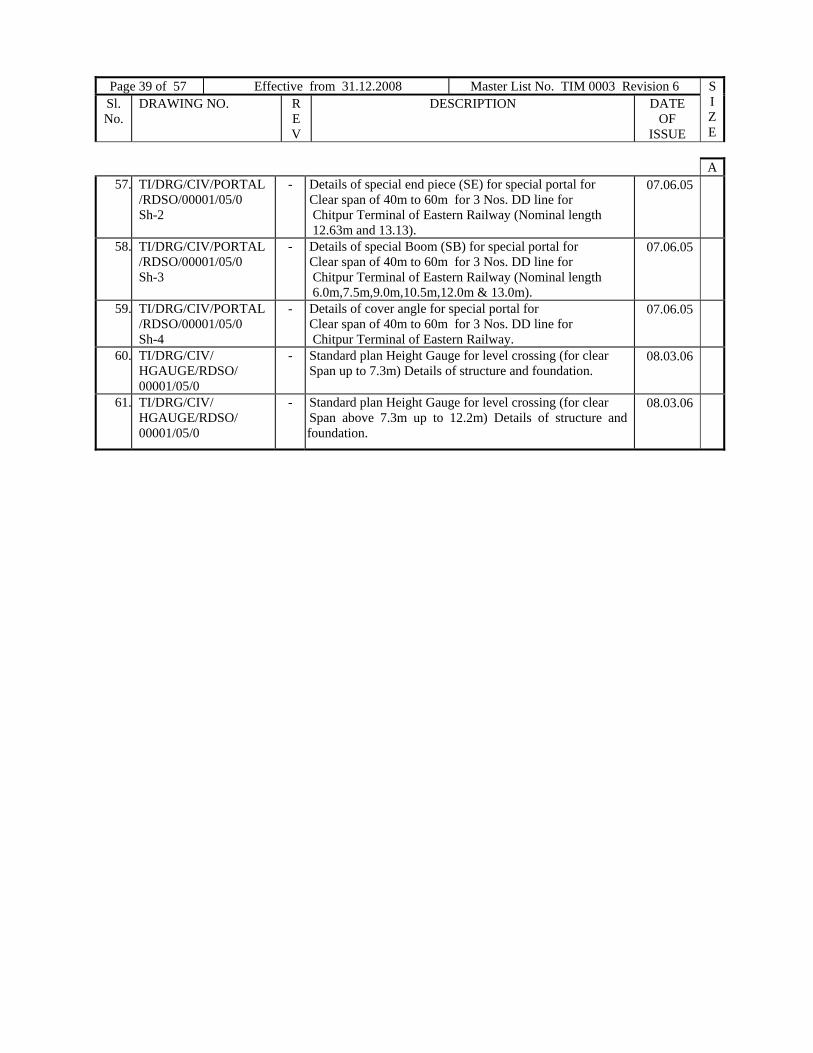
Page 39 of 57 Effective from 31.12.2008 Master List No. TIM 0003 Revision 6 SIZE
Sl. No.
DRAWING NO. REV
DESCRIPTION DATE OF
ISSUE
A57. TI/DRG/CIV/PORTAL
/RDSO/00001/05/0 Sh-2
- Details of special end piece (SE) for special portal for Clear span of 40m to 60m for 3 Nos. DD line for Chitpur Terminal of Eastern Railway (Nominal length 12.63m and 13.13).
07.06.05
58. TI/DRG/CIV/PORTAL /RDSO/00001/05/0 Sh-3
- Details of special Boom (SB) for special portal for Clear span of 40m to 60m for 3 Nos. DD line for Chitpur Terminal of Eastern Railway (Nominal length 6.0m,7.5m,9.0m,10.5m,12.0m & 13.0m).
07.06.05
59. TI/DRG/CIV/PORTAL /RDSO/00001/05/0 Sh-4
- Details of cover angle for special portal for Clear span of 40m to 60m for 3 Nos. DD line for Chitpur Terminal of Eastern Railway.
07.06.05
60. TI/DRG/CIV/ HGAUGE/RDSO/ 00001/05/0
- Standard plan Height Gauge for level crossing (for clear Span up to 7.3m) Details of structure and foundation.
08.03.06
61. TI/DRG/CIV/ HGAUGE/RDSO/ 00001/05/0
- Standard plan Height Gauge for level crossing (for clear Span above 7.3m up to 12.2m) Details of structure and foundation.
08.03.06

Page 40 of 57 Effective from Feb, 2010 Master List No. TIM 0003 Revision 7 SIZE
Sl. No.
DRAWING NO.
REV
DESCRIPTION
DATE OF
ISSUE
Chapter - III - CIVIL
3. STRUCTURAL LAYOUT, STRUCTURES AND FOUNDATIONS FOR TRACTION SUB STATION.
A
1.
ETI/C/0200 SH-1 H Structural layout 132/25 kV traction substation (Type I to VI).
15.05.01
0
2. ETI/C/0200 SH-2 D Structural layout 132/25 kV traction substation (Type VII to X).
15.05.01
0
3. ETI/C/0201 D Details of beam B/1. 15.05.01 1 4. ETI/C/0202 H Details of tower T1. 15.05.01 0 5. ETI/C/0203 G Details of tower T2. 06.03.91 0 6. ETI/C/0204 E Extension of tower T1. 06.03.91 1 7. ETI/C/0205 E Extension of tower T2. 05.03.91 1 8. ETI/C/0206 D Foundation and stub details for towers T1 & T1 extension. 05.03.91 2 9. ETI/C/0207 D Foundation and stub details for towers T2 & T2 extension. 04.03.91
1
10. ETI/C/0208 E Details of beam B/2 & column C/1 for 132/25 kV station. 05.03.91
1
11. ETI/C/0210 F Typical cable trench and foundation layout of 132/25 kV traction substation (Trench cover improved).
06.03.91
0
12. ETI/C/0211 B Foundation and stub details of towers T1 extension and T2 extension for 132/25 kV type VI substation only.
05.03.91
2
13. ETI/C/0213
D Details of baffle wall at traction substation in zones of wind pressure 112.5 and 75 kgf/m2.
03.09.84
1
14. ETI/C/0214
B Details of RCC Baffle wall at traction substations in zones of wind pressure 150 kgf/m2.
03.09.84 2
15. ETI/C/0216 B Transformer oil drainage arrangement at substation. 11.11.88 2 16. ETI/C/0217 SH-1
C Lifting frame for 13.5 MVA transformer core in traction
substation, General arrangement 06.03.91 1
17. ETI/C/0217 SH-2 C Lifting frame for 13.5 MVA transformer core in traction substation, Small part steel works.
06.03.91 1
18. ETI/C/0217 SH-3 B Lifting frame for 13.5 MVA transformer core in traction substation. Small part steel works& Lifting hook details.
05.03.91 1
19. ETI/C/0217 SH-4 A Lifting frame for 13.5 MVA transformer core in traction substation. Details of pavement and drains.
19.11.84 2
20. ETI/C/0219 - Part layout of foundation and cable trench for 25 kV feeder bay for yard/electric loco shed.
01.05.86 2
21. ETI/C/0220 - Part layout of foundation and cable trench for shunt capacitor bay.
29.04.86 1
22. ETI/C/0222
- Line diagram of structural layout of 220/25 kV traction substation.
18.06.87
1
23. ETI/C/0222-I - Structural layout of 220/27 kV traction substation (Type-I).
26.05.97 1
24. ETI/C/0223 A Typical cable trench layout of 220/25 kV traction substation.
01.07.88 1

Page 41 of 57 Effective from 31.12.2008 Master List No. TIM 0003 Revision 6 SIZE
Sl. No.
DRAWING NO. REV
DESCRIPTION DATE OF
ISSUE
A25. ETI/C/0223-I - Layout of typical cable trench 220/27 kV traction
substation (type-I). 26.05.97 1
26. ETI/C/0224 A Details of beam B/4 for 132/25 kV traction substation. 05.03.91 1 27. ETI/C/0225 SH-1/2 - Control room for traction substation. 17.08.88 1 28. ETI/C/0225 SH-2/2 - Control room for traction substation RCC Details. 04.08.88 1 29. ETI/C/0226 - Foundation for towers T1 and T1 Extension for 132/25 kV
traction substation (For ZEBRA conductor). 01.08.88
2
30. ETI/C/0227
- Foundation for towers T2 and T2 Extension for 132/25 kV traction substation (For ZEBRA conductor).
01.08.88
2
31. ETI/C/0228 - Foundation for towers T1 Extension and T2 Extension for 132/25 kV (type VI substation for ZEBRA conductor).
01.08.88
2
32. ETI/C/0300 E Details of structure for 132 kV potential transformers. 06.03.91 1 33. ETI/C/0310 G Details of structure for 132 kV double poles Isolator. 05.03.91 1 34. ETI/C/0320 E Details of structure for 132 kV support insulator. 05.03.91 1 35. ETI/C/0330 F Details of structure for 132 kV current transformers. 05.03.91 1 36. ETI/C/0340 F Details of structure for 120 kV lightning arrester. 06.03.91 1 37. ETI/C/0350 E Details of structure for 132 kV triple pole Isolator 06.03.91 1 38. ETI/C/0360 F Details Of structure for 25 kV current transformer 06.03.91 2 39. ETI/C/0370 SH-1. J Details of structure for 42 kV 10 kA lightning arrester and
25 kV support insulator. 05.03.91 1
40. ETI/C/0370 SH-2 - Black weight of structure for 42 kV 10 kA lightning arrester and 25 kV support insulator.
26.09.89 2
41. ETI/C/0380 F Details of structure for 25 kV single poles Isolator. 05.03.91 1 42. ETI/C/0390 E Details of structure for 25 kV potential transformers. 05.03.91 1 43. ETI/C/0400 G Details of structure for 132 kV double and triple poles
MOCB. 05.03.91
0
44. ETI/C/0410 B Details of structure for 3000 kVA shunt capacitors.
06.03.91 2
45. ETI/C/0420 B Details of mounting structure for 25 kV single phases MOCB type TRE 36.12.
06.03.91 2
46. ETI/C/0430
A Structural details for mounting of 7.5 kV/132 V double pole RVT.
06.03.91 1
47. ETI/C/0440
A Foundation and details of structure for mounting of 100 kVA, 25 kV/230 V LT supply transformer at traction substation
04.03.91 2
48. ETI/SK/C/179 A Details of structure for 66 kV DP Isolator. 05.12.88 1 49. ETI/SK/C/180 C Details of structure and foundation for 25 kV DP Isolator at
traction substation. 04.03.91 1
50. ETI/SK/C/183 A Details of structure strengthening for 132 kV CT ,LA and PT.
06.03.91 1
51. ETI/SK/C/188 A Strengthening of mounting structure for 132 kV CT, LA and PT.
05.03.91 2

Page 42 of 57 Effective from Feb, 2010 Master List No. TIM 0003 Revision 7 SIZE
Sl. No.
DRAWING NO.
REV
DESCRIPTION
DATE OF
ISSUE
Chapter - III - CIVIL
4. STRUCTURES, FENCING AND SPS FOR SWITCHING STATION AND BOOSTER
TRANSFORMER
A 1 ETI/C/0030 F Drilling schedule for S1 mast. 14.08.98 2 2 ETI/C/0031 D Drilling schedule for S2 mast. 14.08.98 2 3 ETI/C/0033 D Details of anchor beam for SP, SSP & FP. 05.03.91 1 4 ETI/C/0034 SH-1 K Details of SPS for switching station 04.03.91 0 5 ETI/C/0034 SH-2 B Details of bracing for switching and BT mast. 04.03.91 2 6 ETI/C/0034 SH-3 A Details of SPS for switching station. 04.03.91 1 7 ETI/C/0036
E Drilling schedule for 8’’x 6’’x 35 lbs RSJ masts 8.0 m
long for BT station type S4. 14.08.98 2
8 ETI/C/0037 C Details of SPS of outrigger for Switching station and BT stations.
05.03.91 1
9 ETI/C/0038 E Details of precast cable trench for SWS station. 04.08.88 1 10 ETI/C/0040 E Details of SPS for BT station. 04.03.91 0 11 ETI/C/0042 E Drilling schedule for S-5 mast (11.4 m long). 14.08.98 2 12 ETI/C/0043 B S-100 fabricated mast for Mounting LT supply
transformer and dropout fuse switch at Switching station 04.03.91 1
13 ETI/C/0044 A S-101 details of mast for Supporting Isolator inside Switching station.
04.03.91 2
14 ETI/C/0067 B Details of remote control cubical (foundation, RCC slab, building plan and steel door).
04.03.91 0
15 ETI/C/0180 C Drilling schedule for S-3 mast (11.4 m long). 14.08.98 2 16 ETI/C/0181 C Drilling schedule for S-6 mast (12.4 m long). 14.08.98 2 17 ETI/C/0182 C Drilling schedule for S-7 mast (12.4 m long). 14.08.98 2 18 ETI/C/0183 C Drilling schedule for S-8 mast (12.4 m long). 14.08.98 1 19 ETI/C/0184 C Drilling schedule for S-9 mast (9.4 m long). 14.08.98 2 20 ETI/C/0185 B Employment schedule for Switching and booster station
main mast 18.07.77 1
21 ETI/C/0186 SH-1 E General arrangement and details of Fencing panel and gate for Switching station.
04.03.91 1
22 ETI/C/0186 SH-2 E Details of Fencing upright and ant climbing device for switching station
10.06.94 1
23 ETI/C/0187
A Mounting arrangement for FLASHER on OHE mast. 05.03.91 1
24 ETI/C/0188-B
D General arrangement and SPS details for mounting DP Isolator on K-250/ B-250 mast at switching station.
04.03.91 1
25 ETI/C/0189 SH-1 A Structural assembly for 280 kVA booster transformer station (without cross feeder and 42 kV lightning arrester).
17.03.88
1
26 ETI/C/0189 SH-2 B Details of beam B-100-A for 280 kVA BT support (Span 3.2 m).
05.03.91 2

Page 43 of 57 Effective from 31.12.2008 Master List No. TIM 0003 Revision 6 SIZE
Sl. No.
DRAWING NO. REV
DESCRIPTION DATE OF
ISSUE
A27 ETI/C/0189 SH-3 B Details of top beam B-102/1-A for 280 kVA BT to
support insulator and lightning arrester (span 3.2 m). 05.03.91 3
28 ETI/C/0190 A Details of beam B-100-B for 280 kVA BT support (span 4.3 m).
06.03.91 2
29 ETI/C/0191 - SPS Details for mounting of A.T. on OHE mast (typical).
30.11.92 1
30 ETI/C/0192 SH-1 A Typical structural assembly for simplified switching station (3 interrupters)
01.03.94 1
31 ETI/C/0192 SH-2 - Typical structural assembly for simplified switching station (3 interrupters). SPS Details.
23.07.93 1
32 ETI/C/0192 SH-3
A Typical structural assembly for simplified switching station (3 interrupters).SPS Details.
01.03.94 1
33 ETI/C/0193 SH-1 - Typical structural assembly for simplified switching station (Single interrupter)
07.04.94 2
34 ETI/C/0193 SH-2 Typical structural assembly for simplified switching station (Single interrupter) SPS Details.
07.04.94 1
35 ETI/C/0194 SH-1 Typical structural assembly for simplified sectioning and paralleling station.
03.01.95 1
36 ETI/C/0194 SH-2 - Typical structural assembly for simplified sectioning and paralleling station.(SPS Details).
03.01.95 0
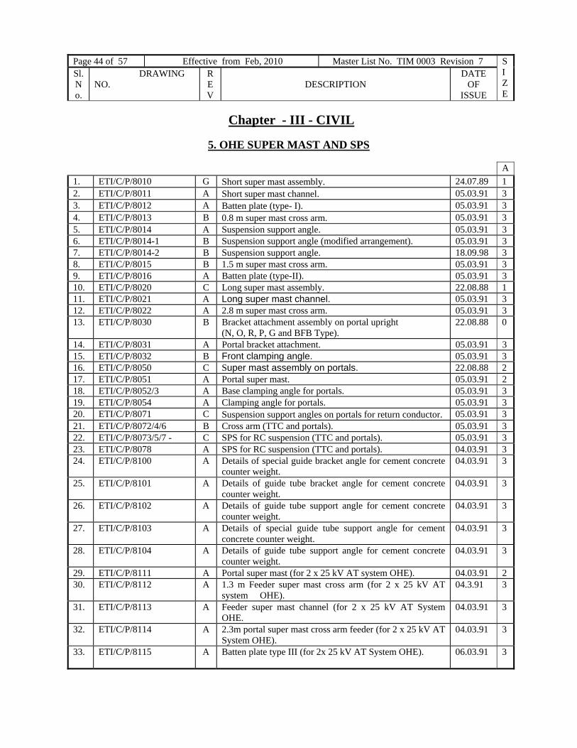
Page 44 of 57 Effective from Feb, 2010 Master List No. TIM 0003 Revision 7 SIZE
Sl. No.
DRAWING NO.
REV
DESCRIPTION
DATE OF
ISSUE
Chapter - III - CIVIL
5. OHE SUPER MAST AND SPS
A 1. ETI/C/P/8010 G Short super mast assembly. 24.07.89 1 2. ETI/C/P/8011 A Short super mast channel. 05.03.91 3 3. ETI/C/P/8012 A Batten plate (type- I). 05.03.91 3 4. ETI/C/P/8013 B 0.8 m super mast cross arm. 05.03.91 3 5. ETI/C/P/8014 A Suspension support angle. 05.03.91 3 6. ETI/C/P/8014-1 B Suspension support angle (modified arrangement). 05.03.91 3 7. ETI/C/P/8014-2 B Suspension support angle. 18.09.98 3 8. ETI/C/P/8015 B 1.5 m super mast cross arm. 05.03.91 3 9. ETI/C/P/8016 A Batten plate (type-II). 05.03.91 3 10. ETI/C/P/8020 C Long super mast assembly. 22.08.88 1 11. ETI/C/P/8021 A Long super mast channel. 05.03.91 3 12. ETI/C/P/8022 A 2.8 m super mast cross arm. 05.03.91 3 13. ETI/C/P/8030 B Bracket attachment assembly on portal upright
(N, O, R, P, G and BFB Type). 22.08.88 0
14. ETI/C/P/8031 A Portal bracket attachment. 05.03.91 3 15. ETI/C/P/8032 B Front clamping angle. 05.03.91 3 16. ETI/C/P/8050 C Super mast assembly on portals. 22.08.88 2 17. ETI/C/P/8051 A Portal super mast. 05.03.91 2 18. ETI/C/P/8052/3 A Base clamping angle for portals. 05.03.91 3 19. ETI/C/P/8054 A Clamping angle for portals. 05.03.91 3 20. ETI/C/P/8071 C Suspension support angles on portals for return conductor. 05.03.91 3 21. ETI/C/P/8072/4/6 B Cross arm (TTC and portals). 05.03.91 3 22. ETI/C/P/8073/5/7 - C SPS for RC suspension (TTC and portals). 05.03.91 3 23. ETI/C/P/8078 A SPS for RC suspension (TTC and portals). 04.03.91 3 24. ETI/C/P/8100 A Details of special guide bracket angle for cement concrete
counter weight. 04.03.91 3
25. ETI/C/P/8101 A Details of guide tube bracket angle for cement concrete counter weight.
04.03.91 3
26. ETI/C/P/8102 A Details of guide tube support angle for cement concrete counter weight.
04.03.91 3
27. ETI/C/P/8103 A Details of special guide tube support angle for cement concrete counter weight.
04.03.91 3
28. ETI/C/P/8104 A Details of guide tube support angle for cement concrete counter weight.
04.03.91 3
29. ETI/C/P/8111 A Portal super mast (for 2 x 25 kV AT system OHE). 04.03.91 2 30. ETI/C/P/8112 A 1.3 m Feeder super mast cross arm (for 2 x 25 kV AT
system OHE). 04.3.91 3
31. ETI/C/P/8113 A Feeder super mast channel (for 2 x 25 kV AT System OHE.
04.03.91 3
32. ETI/C/P/8114 A 2.3m portal super mast cross arm feeder (for 2 x 25 kV AT System OHE).
04.03.91 3
33. ETI/C/P/8115 A Batten plate type III (for 2x 25 kV AT System OHE). 06.03.91 3

Page 45 of 57 Effective from 31.12.2008 Master List No. TIM 0003 Revision 6 SIZE
Sl. No.
DRAWING NO. REV
DESCRIPTION DATE OF
ISSUE
A34. ETI/C/P/8116 A Cleat angle (for 2 X 25 kV AT System OHE 04.03.91 3 35. ETI/C/P/8117
A Suspension support angle (for 2 x25 kV AT system
OHE). 04.03.91 3
36. ETI/C/P/8118 A Feeder support clamp (for 2 X25 kV AT System OHE). 04.03.91 3 37. ETI/C/P/8119 SH-1
- SPS details for double pole Isolator on mast (for 2 x 25
kV). 20.12.91 1
38. ETI/C/P/8119 SH-2
- SPS details for double pole Isolator on `N’ & `O’ type portals (for 2 x 25 kV).
13.10.92 1
39. ETI/C/P/8120 SH-1
- General arrangement of short super mast assembly for TM series mast.
- 06.07.94
1
40. ETI/C/P/8120 SH-2
- Short super mast assembly for TM series mast (SPS details).
06.07.94 2

Page 46 of 57 Effective from Feb, 2010 Master List No. TIM 0003 Revision 7 SIZE
Sl. No.
DRAWING NO.
REV
DESCRIPTION
DATE OF
ISSUE
Chapter - III - CIVIL
6) EMPLOYMENT SCHEDULE OF OHE MASTS
A 1. ETI/OHE/G/00125 SH1 A Employment schedule for cantilever mast regulated OHE
Al caty-65and 107-cu cont wire. WP 112.5kgf/m2 -- OHE only.
20.09.05 2
2. ETI/OHE/G/00125 SH2 A Employment schedule for cantilever mast regulated OHE Al caty-65and 107-cu cont wire. WP 112.5kgf/m2 -- OHE + EW.
20.09.05 2
3. ETI/OHE/G/00125 SH3 A Employment schedule for cantilever mast regulated OHE Al caty-65and 107-cu cont wire. WP 112.5kgf/m2 -- OHE + RC.
20.09.05 2
4. ETI/OHE/G/00125 SH4 A Employment schedule for cantilever mast regulated OHE Al caty-65and 107-cu cont wire. WP 112.5kgf/m2 -- OHE + EW + RC.
20.09.05 2
5. ETI/OHE/G/00153 SH1 F Employment schedule for cantilever mast regulated OHE caty 65/cu and cont 107/cu, WP 112.5 kgf/m2 -- OHE only.
20.09.05 2
6. ETI/OHE/G/00153 SH2 F Employment schedule for cantilever mast regulated OHE caty 65/cu and cont 107/cu, WP 112.5 kgf/m2 -- OHE + EW.
20.09.05 2
7. ETI/OHE/G/00153 SH3 F Employment schedule for cantilever mast regulated OHE caty 65/cu and cont 107/cu, WP 112.5 kgf/m2 -- OHE + RC.
20.09.05 2
8. ETI/OHE/G/00153 SH4 E Employment schedule for cantilever mast regulated OHE caty 65/cu and cont 107/cu, WP 112.5 kgf/m2 --OHE + EW + RC.
20.09.05 2
9. ETI/OHE/G/00154 D Employment schedule for cantilever mast unregulated OHE caty 65/cu & cont 107/cu WP 112.5 kgf/m2 at 35 degree C and with 28 kgf/m2 at 4 degree C without (EW & RC).
09.08.85 2
10. ETI/OHE/G/00156 D Employment schedule for OHE masts unregulated OHE without RC and also without EW (WP = 150 kgf/m2 at 10 degree C.
31.03.77 2
11. ETI/C/0700 SH-1 - Employment schedule for cantilever masts regulated OHE in Gr.40 A for TARE section only (wind 150 kgf/m2) caty.65/cu, cont.107/cu. OHE only.
06.11.80 2
12. ETI/C/0700 SH-2 - Employment schedule for cantilever masts regulated OHE in Gr.40 A for TARE section only (wind 150 kgf/m2) caty.65/cu, cont.107/cu. OHE+EW.
06.11.80 2
13. ETI/C/0700 SH-3 - Employment schedule for cantilever masts regulated OHE in Gr.40 A for TARE section only (wind 150 kgf/m2) caty.65/cu, cont.107/cu. OHE+RC.
06.11.80 2
14. ETI/C/0700 SH-4 - Employment schedule for cantilever masts regulated OHE in Gr.40 A for TARE section only (wind 150 kgf/m2) caty.65/cu, cont.107/cu. OHE+RC+EW.
06.11.80 2

Page 47 of 57 Effective from 31.12.2008 Master List No. TIM 0003 Revision 6 SIZE
Sl. No.
DRAWING NO. REV
DESCRIPTION DATE OF
ISSUE
A 15. ETI/C/0700 SH-5 - Employment schedule for cantilever masts regulated
OHE in Gr.40 A for TARE section only (wind 150 kgf/m2) caty.65/cu, cont.107/cu. UNREGULATED OHE only.
06.11.79 2
16. ETI/C/0700 SH-6 B Employment schedule for cantilever masts regulated OHE in Gr.40 A for TARE section only (wind 150 kgf/m2) caty.65/cu, cont.107/cu. Notes. (General)
20.09.05 2
17. ETI/C/0701 SH-1 B Employment schedule for cantilever mast regulated OHE for TARE section, wind 150 kgf/m2 (Gr. 40A) only, caty.115/Al, cont. 107/cu. OHE only.
20.09.05 2
18. ETI/C/0701 SH-2 B Employment schedule for cantilever mast regulated OHE for TARE section, wind 150 kgf/m2 (Gr. 40A) only, caty.115/Al, cont. 107/cu. OHE +EW.
20.09.05 2
19. ETI/C/0701 SH-3 B Employment schedule for cantilever mast regulated OHE for TARE section, wind 150 kgf/m2 (Gr. 40A) only, caty.115/Al, cont. 107/cu. OHE +RC.
20.09.05 2
20. ETI/C/0701 SH-4 B Employment schedule for cantilever mast regulated OHE for TARE section, wind 150 kgf/m2 (Gr. 40A) only, caty.115/Al, cont. 107/cu. OHE +EW+ RC.
20.09.05 2
21. ETI/C/0702 SH-1 B Employment schedule for cantilever mast regulated OHE caty. 65/cu, cont.107/cu (WP 75 kgf/m2). OHE only.
20.09.05 2
22. ETI/C/0702 SH-2 B Employment schedule for cantilever mast regulated OHE caty. 65/cu, cont.107/cu (WP 75 kgf/m2). OHE +EW.
20.09.05 2
23. ETI/C/0702 SH-3 B Employment schedule for cantilever mast regulated OHE caty. 65/cu, cont.107/cu (WP 75 kgf/m2). EW+ RC.
20.09.05 2
24. ETI/C/0702 SH-4 B Employment schedule for cantilever mast regulated OHE caty. 65/cu, cont.107/cu (WP 75 kgf/m2). OHE + EW+ RC.
20.09.05 2
25. ETI/C/0702 SH-5 B Employment schedule for cantilever mast regulated OHE caty. 65/cu, cont.107/cu (WP 75 kgf/m2). Unregulated OHE.
20.09.05 2
26. ETI/C/0703 SH-1 A Employment schedule for cantilever mast regulated OHE caty.115/Al, cont.107/cu (WP 75 kgf/m2) OHE only.
20.09.05 2
27. ETI/C/0703 SH-2 A Employment schedule for cantilever mast regulated OHE caty.115/Al, cont.107/cu (WP 75 kgf/m2) OHE + EW.
20.09.05 2
28. ETI/C/0703 SH-3 A Employment schedule for cantilever mast regulated OHE caty.115/Al, cont.107/cu (WP 75 kgf/m2) OHE + RC.
20.09.05 2
29. ETI/C/0703 SH-4 A Employment schedule for cantilever mast regulated OHE caty.115/Al, cont.107/cu (WP 75 kgf/m2) OHE + EW + RC.
20.09.05 2
30. ETI/C/0704 B Employment schedule for Tramway type regulated OHE (WP 75kgf/m2) without EW and without RC.
20.09.05 2
31. ETI/C/0705 B Employment schedule for Tramway type regulated OHE (WP 112.5 kgf/m2) without EW and without RC.
20.09.05 2
32. ETI/C/0706 B Employment schedule for Tramway type regulated OHE (WP 150 kgf/m2) without EW and without RC.
20.09.05 2

Page 48 of 57 Effective from Feb, 2010 Master List No. TIM 0003 Revision 7 SIZE
Sl. No.
DRAWING NO.
REV
DESCRIPTION
DATE OF
ISSUE
A 33. ETI/C/0707 A Employment schedule for 8” X 8” X 35 lbs BFB (9.5m
long) (WP 150 kgf/m2) for TARE section Gr. 40A only.(Cu OHE)
20.09.05 2
34. ETI/C/0708 B Employment schedule for 8” X 8” X 35 lbs BFB (9.5 m long) (WP 112.5 kgf/m2) caty 65/cu and cont 107/cu.
20.09.05 2
35. ETI/C/0709 A Employment schedule for OHE mast overlap central location with 3.0m implantation .Caty 65/cu and Cont 107/cu. WP 75 Kgf/m2
08.08.85 2
36. ETI/C/0710 A Employment schedule for OHE mast (9.5m) overlap central location with 3.0m implantation. Caty 65/cu and Cont 107/cu WP 112.5 kgf/m2.
08.08.85 2
37. ETI/C/0711 A Employment schedule for OHE mast (9.5m) overlap inter location with 3.0m implantation. Caty 65/cu and Cont 107/cu. WP 75 kgf/m2.
08.08.85 2
38. ETI/C/0712 A Employment schedule for OHE mast (9.5m) overlap inter location with 3.0m implantation. Caty 65/cu and Cont 107/cu. WP 112.5 kgf/m2.
08.08.85 2
39. ETI/C/0713 B Employment schedule for 9.5m long 200X200X49.9 kg mast Caty 65/cu and Cont 107/cu, WP 75 kgf/m2.
20.09.05 2
40. ETI/C/0714 B Employment schedule for 9.5m long 200X200X49.9 kg mast Caty 65/cu and Cont 107/cu, WP 112.5 kgf/m2.
20.09.05 2
41. ETI/C/0715 A Employment schedule for OHE mast (9.5m) overlap anchor location with 3.0m implantation .Caty 65/cu and Cont 107/cu WP 75 kgf/m2.
08.08.85 2
42. ETI/C/0716 A Employment schedule for OHE mast (9.5m) overlap anchor location with 3.0m implantation. Caty 65/cu and Cont 107/cu.WP 112.5 kgf/m2.
08.08.85 2
43. ETI/C/0717 SH-1 A Employment schedule for OHE mast (9.5m) wind pressure 112.5 kgf/m2 for composite OHE (1000+1000) kgf tension. OHE only.
21.09.05 2
44. ETI/C/0717 SH-2 A Employment schedule for OHE mast (9.5m) wind pressure 112.5 kgf/m2 for composite OHE (1000+1000) kgf tension. OHE + EW.
21.09.05 2
45. ETI/C/0717 SH-3 A Employment schedule for OHE mast (9.5m) wind pressure 112.5 kgf/m2 for composite OHE (1000+1000) kgf tension. OHE + RC.
21.09.05 2
46. ETI/C/0717 SH-4 A Employment schedule for OHE mast (9.5m) wind pressure 112.5 kgf/m2 for composite OHE (1000+1000) kgf tension. OHE + EW+RC.
21.09.05 2
47. ETI/C/0718 B Employment schedule for OHE mast (9.5m) wind pressure 112.5kgf/m2 with 3.0m implantation composite OHE (1000+ 1000) kgf tension. Overlap anchor location.
19.10.05 2
48. ETI/C/0719 B Employment schedule for OHE mast (9.5m) wind pressure 112.5 kgf/m2 with 3.0m implantation composite OHE (1000 + 1000) kgf tension overlap central location.
19.10.05 2

Page 49 of 57 Effective from 31.12.2008 Master List No. TIM 0003 Revision 6 SIZE
Sl. No.
DRAWING NO. REV
DESCRIPTION DATE OF
ISSUE
A 49. ETI/C/0720 B Employment schedule for OHE mast (9.5m)wind
pressure 112.5kgf/m2 with 3.0m implantation composite OHE (1000 + 1000) kgf Tension . Overlaps inter location.
19.10.05 2
50. ETI/C/0721 SH-1 - Employment schedule for regulated OHE mast (9.5m) wind pressure 75kgf/m2 for composite OHE (1000+1000) kgf tension. OHE only.
26.08.86 2
51. ETI/C/0721 SH-2 - Employment schedule for regulated OHE mast (9.5m) wind pressure 75kgf/m2 for composite OHE (1000+1000) kgf tension. OHE + EW
26.08.86 2
52. ETI/C/0721 SH-3 - Employment schedule for regulated OHE mast (9.5m) wind pressure 75kgf/m2 for composite OHE (1000+1000) kgf tension. OHE + RC
26.08.86 2
53. ETI/C/0721 SH-4 - Employment schedule for regulated OHE mast (9.5m) wind pressure 75kgf/m2 for composite OHE (1000+1000) kgf tension. OHE+EW+RC
26.08.86 2
54. ETI/C/0722
- Employment schedule for regulated OHE mast (9.5m)wind pressure 75 kgf/m2 for composite OHE with extra setting distance. Overlap anchor location.
01.09.86 2
55. ETI/C/0723 - Employment schedule for regulated OHE mast (9.5m) wind pressure 75 kgf/m2 for composite OHE with extra setting distance. Overlap central location.
01.09.86 2
56. ETI/C/0725 A Employment schedule for prestressed spun concrete mast (PC 42) 9.5 m long. Conventional OHE, normal location WP 150, 112.5 and 75 kgf/m2.
14.12.89 2
57. ETI/C/0724 - Employment schedule for regulated OHE mast (9.5m) wind pressure 75 kgf/m2 for composite OHE with extra setting distance. Overlap inters location.
01.09.86 2
58. ETI/C/0726 SH-1 - Employment schedule for OHE mast (9.5m) for wind pressure 150kgf/m2 copper OHE. --OHE only
19.07.88 2
59. ETI/C/0726 SH-2 - Employment schedule for OHE mast (9.5m) for wind pressure 150kgf/m2 copper OHE. --OHE + EW
19.07.88 2
60. ETI/C/0726 SH-3 - Employment schedule for OHE mast (9.5m) for wind pressure 150kgf/m2 copper OHE. --OHE + RC
19.07.88 2
61. ETI/C/0726 SH-4 - Employment schedule for OHE mast (9.5m) for wind pressure 150 kgf/m2 copper OHE. -- OHE + EW + RC.
19.07.88 2
62. ETI/C/0727 - Employment schedule for OHE mast (9.5m) for wind pressure 150kgf/m2 copper OHE, with Higher Implantation. Overlap anchor location.
19.07.88 2
63. ETI/C/0728 - Employment schedule for OHE mast (9.5m) for wind pressure 150kgf/m2 copper OHE, with Higher Implantation. Overlap central location.
19.07.88 2
64. ETI/C/0729 - Employment schedule for OHE mast (9.5m) for wind pressure 150kgf/m2 copper OHE, with Higher Implantation. Overlap inter location
19.07.88 2
65. ETI/C/0730 SH-1 - Employment schedule for OHE mast (9.5m) Wind-112.5 kgf/m2 copper OHE, 1200 kg tensions for high speed 160 km/h. --OHE only.
23.12.88 2

Page 50 of 57 Effective from Feb, 2010 Master List No. TIM 0003 Revision 7 SIZE
Sl. No.
DRAWING NO.
REV
DESCRIPTION
DATE OF
ISSUE
A 66. ETI/C/0730 SH-2 - Employment schedule for OHE mast (9.5m) Wind-112.5
kgf/m2 copper OHE, 1200 kg tensions for high speed 160 km/h. -- OHE + EW.
23.12.88 2
67. ETI/C/0730 SH-3 - Employment schedule for OHE mast (9.5m) Wind-112.5 kgf/m2 copper OHE, 1200 kg tensions for high speed 160 km/h --OHE + RC.
23.12.88 2
68. ETI/C/0730 SH-4 - Employment schedule for OHE mast (9.5m) Wind-112.5 kgf/m2 copper OHE, 1200 kg tensions for high speed 160 km/h. --OHE + EW + RC.
23.12.88 2
69. ETI/C/0730-1 - Employment schedule for OHE mast (9.5 m) W.P. 112.5 Kgf/m2copper OHE (1200 + 1200) caty.65 mm2, cont.107mm2 (for high speed 160Kmph) overlap anchor location with 3:1 regulating equipment.
23.12.93 2
70. ETI/C/731 - Employment schedule for OHE mast (9.5m) Wind-112.5 kgf/m2, copper OHE, with 1200 kg tensions, with Higher Implantation for high speed 160 km/h. overlap inter location.
23.12.88 2
71. ETI/C/732 - Employment schedule for OHE mast (9.5m) Wind -112.5 kgf/m2, copper OHE, with 1200 kg tensions, with Higher Implantation for high speed 160 km/h. overlap central location.
23.12.88 2
72. ETI/C/733 - Employment schedule for OHE mast (9.5m) Wind -112.5 kgf/m2, copper OHE, with 1200 kg tensions, with Higher Implantation for high speed 160 km/h. overlap anchor location.
23.12.88 2
73. ETI/C/0733-1 - Employment schedule for OHE mast (9.5m) W.P.112.5 kgf/m2 Copper OHE (1200 + 1200) caty. 65 mm2 cont.107mm2 (For high speed 160 kmph) overlap anchor location with 3:1 regulating equipment (with higher setting).
23.12.93 2
74. ETI/C/0734 SH-1 - Employment Schedule for OHE Mast (9.5 m) wind 75 kgf/m2 AAAOHE, with 1000 kg tensions. OHE only.
08.09.89 2
75. ETI/C/0734 SH-2 - Employment Schedule for OHE Mast (9.5 m) wind 75 kgf/m2 AAA OHE, with 1000 kg tensions OHE+EW.
08.09.89 2
76. ETI/C/0734 SH-3 - Employment Schedule for OHE Mast (9.5 m) wind 75 kgf/m2 AAAOHE, with 1000 kg tensions OHE+RC
08.09.89 2
77. ETI/C/0734 SH-4 - Employment Schedule for OHE Mast (9.5 m) wind 75 kgf/m2 AAA OHE,with 1000 kg tensions OHE+EW+RC
08.09.89
2
78. ETI/C/0735 - Employment Schedule for OHE Mast (9.5 m) wind 75 kgf/m2 AAA OHE, with 1000 kg tension. Overlap central location with higher implantation.
08.09.89 2
79. ETI/C/0736 - Employment Schedule for OHE Mast (9.5 m) wind 75 kgf/m2 AAA OHE, with 1000 kg tension. Overlap inters location with higher implantation.
08.09.89 2
80. ETI/C/0737 - Employment Schedule for OHE Mast (9.5 m) wind 75kgf/m2AAA OHE, with 1000 kg tensions. Overlap anchor location with higher implantation.
08.09.89 2

Page 51 of 57 Effective from 31.12.2008 Master List No. TIM 0003 Revision 6 SIZE
Sl. No.
DRAWING NO. REV
DESCRIPTION DATE OF
ISSUE
A 81. ETI/C/0738 SH-1 - Employment Schedule for OHE Mast (9.5 m) wind 112.5
kgf/m 2 AAA OHE, with 1000 kg tensions OHE only. 08.09.89 2
82. ETI/C/0738 SH-2 - Employment Schedule for OHE Mast (9.5 m) wind 112.5 kgf/m 2 AAA OHE, with 1000 kg tensions OHE + EW
08.09.89 2
83. ETI/C/0738 SH-3 - Employment Schedule for OHE Mast (9.5 m) wind 112.5 kgf/m 2 AAA OHE, with 1000 kg tensions. OHE + RC
08.09.89 2
84. ETI/C/0738 SH-4 - Employment Schedule for OHE Mast (9.5 m) wind 112.5 kgf/m 2 AAA OHE, with 1000 kg tensions. OHE +EW +RC
08.09.89 2
85. ETI/C/0739 - Employment Schedule for OHE Mast (9.5 m) wind 112.5 kgf/m 2 AAA OHE, with 1000 kg tensions. Overlap central location with higher implantation
08.09.89
2
86. ETI/C/0740 - Employment Schedule for OHE Mast (9.5 m) wind 112.5 kgf/m 2 AAA OHE, with 1000 kg tensions. Overlap inter location with higher implantation
08.09.89 2
87. ETI/C/0741 - Employment Schedule for OHE Mast (9.5 m) wind 112.5 kgf/m 2 AAA OHE, with 1000 kg tensions. Overlap anchor location with higher implantation
08.09.89 2
88. ETI/C/0742 SH-1 - Employment schedule for OHE mast (9.5 m) for 2 X 25 kV with copper OHE with (1000+1000) tension, wind pressure 112.5 kgf/m 2. (OHE+AT feeder) and without EW.
23.10.89 2
89. ETI/C/0742 SH-2 - Employment schedule for OHE mast (9.5 m) for 2 X 25 kV with copper OHE with (1000+1000) tension, wind pressure 112.5 Kgf/m 2. (OHE+AT feeder), without EW and with extra setting.
23.10.89 2
90. ETI/C/0742 SH-3 - Employment schedule for OHE mast (9.5 m) for 2 X 25 kV with copper OHE with (1000+1000) tension, wind pressure 112.5 Kgf/m 2. (OHE+AT feeder) + EW.
23.10.89 2
91. ETI/C/0742 SH-4 - Employment schedule for OHE mast (9.5 m) for 2 X 25 kV with copper OHE with (1000+1000) tension, wind pressure 112.5 Kgf/m 2. (OHE+AT feeder) + EW and with extra setting.
23.10.89 2
92. ETI/C/0743 SH-1 - Employment schedule for OHE Mast (9.5 m) for 2 X 25 kV composite OHE with (1000+1000) tension, wind pressure 112.5 Kgf/m 2. (OHE+AT feeder) and without EW.
07.02.90 2
93. ETI/C/0743 SH-2 - Employment schedule for OHE Mast (9.5 m) for 2 X 25 kV composite OHE with (1000+1000) tension, wind pressure 112.5 Kgf/m 2. (OHE+AT feeder),without EW and with extra setting.
07.02.90 2
94. ETI/C/0743 SH-3 - Employment schedule for OHE Mast (9.5 m) for 2 X 25 kV composite OHE with (1000+1000) tension, wind pressure 112.5 Kgf/m 2. (OHE+AT feeder +EW).
07.02.90 2

Page 52 of 57 Effective from Feb, 2010 Master List No. TIM 0003 Revision 7 SIZE
Sl. No.
DRAWING NO.
REV
DESCRIPTION
DATE OF
ISSUE
A 95. ETI/C/0743 SH-4 - Employment schedule for OHE Mast (9.5 m) for 2 X 25
kV composite OHE with (1000+1000) tension, wind pressure 112.5 Kgf/m 2. (OHE+AT feeder +EW) and with extra setting.
07.02.90 2
96. ETI/C/0747 SH-1 - Employment schedule for OHE mast (9.5 m), W.P 112.5 kgf/m2 copper OHE (cat. 65 mm2. cont.150 mm2 F.B.) (1200 + 1200 with 3:1 regulating equipment). OHE only.
22.04.93 2
97. ETI/C/0747 SH-2 - Employment schedule for OHE mast (9.5 m), W.P 112.5 kgf/m2 copper OHE (cat. 65 mm2. cont.150 mm2 F.B.) (1200 + 1200 with 3:1 regulating equipment). OHE + EW.
22.04.93 2
98. ETI/C/0747 SH-3 - Employment schedule for OHE mast (9.5 m), W.P 112.5 kgf/m2 copper OHE (cat. 65 mm2. cont.150 mm2 F.B.) (1200 + 1200 with 3:1 regulating equipment). OHE + RC.
22.04.93 2
99. ETI/C/0747 SH-4 - Employment schedule for OHE mast (9.5 m), W.P 112.5 kgf/m2 copper OHE (cat. 65 mm2. cont.150 mm2 F.B.) (1200 + 1200 with 3:1 regulating equipment). OHE + EW + RC.
22.04.93 2
100. ETI/C/0748 - Employment schedule for OHE mast (9.5 m) WP 112.5 kgf/m2 copper OHE (caty. 65 mm2, cont.150 mm2 F.B).with (1200 + 1200) (overlap central location with higher setting).
22.04.93 2
101. ETI/C/0749 - Employment schedule for OHE mast (9.5 m) WP 112.5 kgf/m2 copper OHE (caty. 65 mm2, cont.150 mm2 F.B. with 1200 + 1200) with 3:1 ATD (overlap anchor location with higher setting).
22.04.93 2
102. ETI/C/0750 - Employment schedule for OHE mast (9.5 m) WP 112.5 kgf/m2 copper OHE (caty. 65 mm2, cont.150 mm2 F.B. with 1200 + 1200) (overlap inter location with higher setting).
22.04.93 2
103. ETI/C/0755 SH-1 - Employment Schedule for OHE mast (9.5 m) wind – 150 kgf/m2 cat- 65cu, cont-150 cu (FB) with (800+1200) kgf tension. OHE only.
24.03.95 2
104. ETI/C/0755 SH-2 - Employment Schedule for OHE mast (9.5 m) wind - 150 kgf/m2 cat- 65cu, cont-150 cu (FB) with (800+1200) kgf tension. OHE + EW.
24.03.95 2
105. ETI/C/0755 SH-3 - Employment Schedule for OHE mast (9.5 m) wind – 150 kgf/m2cat- 65cu, cont-150 cu (FB) with (800+1200) kgf tension. OHE + RC.
24.03.95 2
106. ETI/C/0755 SH-4 - Employment Schedule for OHE mast (9.5 m) wind – 150 kgf/m2cat- 65cu, cont-150 cu (FB) with (800+1200) kgf tension. OHE + EW + RC.
24.03.95 2
107. ETI/C/0756 SH-1 Employment Schedule for OHE mast (9.5 m) wind - 75 kgf/m2 cat- 65cu, cont-150 cu FB with (800+1200) kgf tension. OHE only.
24.03.95 2

Page 53 of 57 Effective from 31.12.2008 Master List No. TIM 0003 Revision 6 SIZE
Sl. No.
DRAWING NO. REV
DESCRIPTION DATE OF
ISSUE
A 108. ETI/C/0756 SH-2 - Employment Schedule for OHE mast (9.5 m) wind - 75
kgf/m2 cat- 65cu, cont-150 cu FB with (800+1200) kgf tension. OHE + EW.
24.03.95 2
109. ETI/C/0756 SH-3 - Employment Schedule for OHE mast (9.5 m) wind - 75 kgf/m 2 cat- 65cu, cont-150 cu FB with (800+1200) kgf tension. OHE + RC.
24.03.95 2
110. ETI/C/0756 SH-4 - Employment Schedule for OHE mast (9.5 m) wind - 75 kgf/m2 cat- 65 cu, cont-150 cu FB with (800+1200) kgf tension. OHE + EW + RC.
24.03.95 2
111. ETI/C/0757 SH-1 - Employment Schedule for OHE mast (9.5 m) wind - 112.5kgf/m 2 cat- 65 cu, cont-150 cu FB with (800+1200) kgf tension. OHE only.
24.03.95 2
112. ETI/C/0757 SH-2 - Employment Schedule for OHE mast (9.5 m) wind - 112.5kgf/m 2 cat- 65 cu, cont-150 cu FB with (800+1200) kgf tension. OHE + EW.
24.03.95 2
113. ETI/C/0757 SH-3 - Employment Schedule for OHE mast (9.5 m) wind - 112.5kgf/m 2 cat- 65 cu, cont-150 cu FB with (800+1200) kgf tension. OHE + RC.
24.03.95 2
114. ETI/C/0757 SH-4 - Employment Schedule for OHE mast (9.5 m) wind - 112.5kgf/m 2 cat- 65 cu, cont-150 cu FB with (800+1200) kgf. Tension. OHE + EW + RC.
24.03.95 2
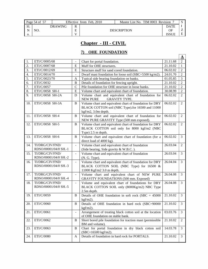
Page 54 of 57 Effective from Feb, 2010 Master List No. TIM 0003 Revision 7 SIZE
Sl. No.
DRAWING NO.
REV
DESCRIPTION
DATE OF
ISSUE
Chapter - III - CIVIL
7) OHE FOUNDATION A
1. ETI/C/0005/68 - Chart for portal foundation. 21.11.68 2 2. ETI/C/0007/68 E Muff for OHE structures. 21.10.02 1 3. ETI/C/0012/69 E Structure muff for sand cored foundation. 06.02.02 2 4. ETI/C/0014/70 - Dwarf mast foundation for loose soil (SBC=5500 kg/m2). 24.01.70 2 5. ETI/C/0023/70 A Typical side bearing foundation on banks. 01.05.85 3 6. ETI/C/0032 B Details of foundation for fencing upright. 21.10.02 2 7. ETI/C/0057 C Pile foundation for OHE structure in loose banks. 21.10.02 2 8. ETI/C/0058 SH-1 E Volume chart and equivalent chart of foundation. 30.08.99 2 9. ETI/C/0058 SH-2A D Volume chart and equivalent chart of foundation for
NEW PURE GRAVITY TYPE. 06.02.02 2
10. ETI/C/0058 SH-3A B Volume chart and equivalent chart of foundation for DRY BLACK COTTON soil (NBC Type).for 16500 and 11000 kgf/m2, 3.0m depth.
06.02.02 2
11. ETI/C/0058 SH-4 B Volume chart and equivalent chart of foundation for NEW PURE GRAVITY Type (500 mm exposed).
06.02.02 2
12. ETI/C/0058 SH-5 B Volume chart and equivalent chart of foundation for DRY BLACK COTTON soil only for 8000 kgf/m2 (NBC Type) 2.5 m depth.
06.02.02 2
13. ETI/C/0058 SH-6 B Volume chart and equivalent chart of foundation (for a direct load of 4000 kg).
06.02.02 3
14. TI/DRG/CIV/FND/ RDSO/00001/04/0 SH.-1
- Volume chart and equivalent chart of foundation (Side bearing, Side gravity & W.B.C. ).
26.03.04 2
15. TI/DRG/CIV/FND/ RDSO/00001/04/0 SH.-2
- Volume chart and equivalent chart of foundation (N. G. Type).
26.03.04 3
16. TI/DRG/CIV/FND/ RDSO/00001/04/0 SH.-3
- Volume chart and equivalent chart of foundation for DRY BLACK COTTON SOIL (NBC Type) for 16500 & 11000 Kgf/m2 3.0 m depth.
26.04.04 3
17. TI/DRG/CIV/FND/ RDSO/00001/04/0 SH.-4
- Volume chart and equivalent chart of NEW PURE GRAVITY FOUNDATIONS (500 mm. Exposed)
26.04.08 3
18. TI/DRG/CIV/FND/ RDSO/00001/04/0 SH.-5
- Volume and equivalent chart of foundations for DRY BLACK COTTON SOIL only (8000Kg/m2) NBC Type 2.5m depth.
26.04.08 3
19. ETI/C/0059 B Details of OHE foundation in soft rock (SBC = 45000 kgf/m2).
21.10.02 3
20. ETI/C/0060 B Details of OHE foundation in hard rock (SBC=90000 kgf/m2).
21.10.02 3
21. ETI/C/0061 - Arrangement of treating black cotton soil at the location of OHE foundation on stable bank.
03.03.76 3
22. ETI/C/0062 B Short bored pile foundation for traction mast (permissible BM and volume).
21.10.02 2
23. ETI/C/0063 B Chart for portal foundation in dry black cotton soil (SBC=16500 kgf/m2).
14.03.78 3
24. ETI/C/0080 A Details of foundation in hard rock for PORTALS. 21.10.02 3

Page 55 of 57 Effective from 31.12.2008 Master List No. TIM 0003 Revision 6 SIZE
Sl. No.
DRAWING NO. REV
DESCRIPTION DATE OF
ISSUE
25. ETI/C/0209
C Details of foundation for 132/25 kV traction substation structures.
21.10.02 0
26. ETI/SK/C/131 - Typical design of pure gravity foundation. 21.12.77 2 27. ETI/SK/C/142 - Typical design of side gravity foundation. 24.02.78 2
Chapter - III - CIVIL
8. MISCELLANEOUS A
1. ETI/C/0002 A Details of base plate for mast on drains in station yards 16.07.70 2 2. ETI/C/0010 C Bolted base connection for portals located in drains. 04.03.91 1 3. ETI/C/0045 SH-1 D 132 kV emergency tower (with RSJ ) outline diagram 18.03.86 2 4. ETI/C/0045 SH-2 E 132 kV emergency tower (with RSJ ) structural drawings 20.08.75 0 5. ETI/C/0068 F Protective screen at foot over and road over bridge. 28.10.99 1 6. ETI/C/0069 C Danger plate in level crossing gauge for electrified section 06.04.00 2
Chapter - III - CIVIL
9. SPUN PRESTRESSED CEMENT CONCRETE (PSC) OHE MAST
1. ETI/SK/C/214 SH-1 E MS Bracket fitting for PSC General arrangement and SPS details
09.02.90 1
2. .ETI/SK/C/214 SH-2 A SPS details for earth wire clamp on PSC mast 22.06.94 2 3. ETI/SK/C/242 A RC arrangement in PSC mast 22-09-95 2 4. ETI/OHE/SK/537 SH-1 D Earthing and bonding of PSC mast. 28.12.94 1 5.
ETI/OHE/SK/537 SH-2
B Typical earthing arrangement in spun PSC mast with 18 mm dia rod.
28.12.94 3
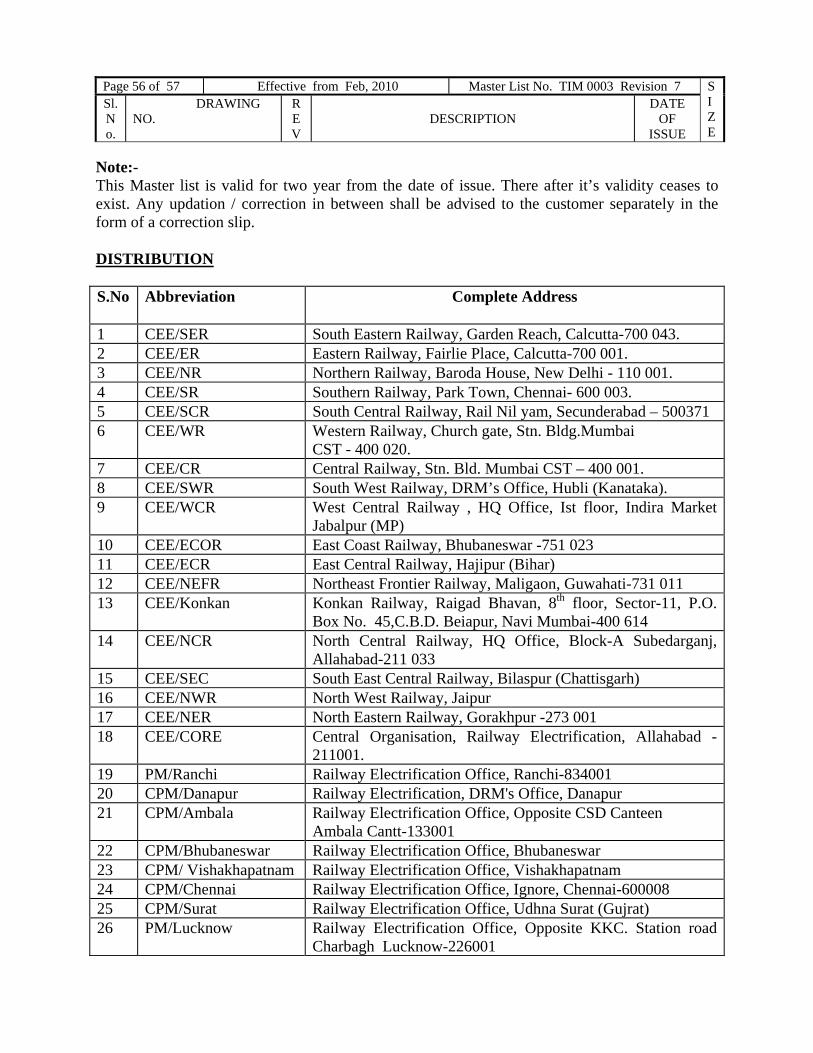
Page 56 of 57 Effective from Feb, 2010 Master List No. TIM 0003 Revision 7 SIZE
Sl. No.
DRAWING NO.
REV
DESCRIPTION
DATE OF
ISSUE
Note:- This Master list is valid for two year from the date of issue. There after it’s validity ceases to exist. Any updation / correction in between shall be advised to the customer separately in the form of a correction slip. DISTRIBUTION S.No Abbreviation Complete Address
1 CEE/SER South Eastern Railway, Garden Reach, Calcutta-700 043. 2 CEE/ER Eastern Railway, Fairlie Place, Calcutta-700 001. 3 CEE/NR Northern Railway, Baroda House, New Delhi - 110 001. 4 CEE/SR Southern Railway, Park Town, Chennai- 600 003. 5 CEE/SCR South Central Railway, Rail Nil yam, Secunderabad – 500371 6 CEE/WR Western Railway, Church gate, Stn. Bldg.Mumbai
CST - 400 020. 7 CEE/CR Central Railway, Stn. Bld. Mumbai CST – 400 001. 8 CEE/SWR South West Railway, DRM’s Office, Hubli (Kanataka). 9 CEE/WCR West Central Railway , HQ Office, Ist floor, Indira Market
Jabalpur (MP) 10 CEE/ECOR East Coast Railway, Bhubaneswar -751 023 11 CEE/ECR East Central Railway, Hajipur (Bihar) 12 CEE/NEFR Northeast Frontier Railway, Maligaon, Guwahati-731 011 13 CEE/Konkan Konkan Railway, Raigad Bhavan, 8th floor, Sector-11, P.O.
Box No. 45,C.B.D. Beiapur, Navi Mumbai-400 614 14 CEE/NCR North Central Railway, HQ Office, Block-A Subedarganj,
Allahabad-211 033 15 CEE/SEC South East Central Railway, Bilaspur (Chattisgarh) 16 CEE/NWR North West Railway, Jaipur 17 CEE/NER North Eastern Railway, Gorakhpur -273 001 18 CEE/CORE Central Organisation, Railway Electrification, Allahabad -
211001. 19 PM/Ranchi Railway Electrification Office, Ranchi-834001 20 CPM/Danapur Railway Electrification, DRM's Office, Danapur 21 CPM/Ambala Railway Electrification Office, Opposite CSD Canteen
Ambala Cantt-133001 22 CPM/Bhubaneswar Railway Electrification Office, Bhubaneswar 23 CPM/ Vishakhapatnam Railway Electrification Office, Vishakhapatnam 24 CPM/Chennai Railway Electrification Office, Ignore, Chennai-600008 25 CPM/Surat Railway Electrification Office, Udhna Surat (Gujrat) 26 PM/Lucknow Railway Electrification Office, Opposite KKC. Station road
Charbagh Lucknow-226001

Page 57 of 57 Effective from 31.12.2008 Master List No. TIM 0003 Revision 6 SIZE
Sl. No.
DRAWING NO. REV
DESCRIPTION DATE OF
ISSUE
27 CEE(Cons) CR Central Railway, 3rd, VT Traction Sub-station Building, D.N.Road, Mumbai CST-400001
28 CEE(Cons) WR Western Railway, Churchgate, Mumbai-400020 29 CEE(Cons) ER Eastern Railway, Fairlie Place, Calcutta-700001 30 CEE(Cons) NR N. Railway, Baroda House, New Delhi-110001 31 CEE(Cons) SR Southern Railway, Park Town, Chennai-600003 32 CEE(Cons) SER S.E.Railway, Garden Reach, Calcutta-700043 33 CEE(Cons) SCR S.C.Railway, Rail Nil yam, Secunderabad-500371 34 CEE ( Conv.) 2nd Floor , Parcel Office Building ,
Mumbai-4000 01 35 CPM ( Conv.) 3rd Floor, New Annexe. Building, New Administrative office.
Opposite Times Of India Bldg, Mumbai- 4000 01 36 Director/IRIEEN Director, Indian Railways Institute of Electrical Engineering,
Post Box No.233, Nasik Road-422101 37 SECY/Elec./Rly. Bd. Railway Board, Rail Bhavan, New Delhi - 110 001. 38 SECY/RE/RLY.Bd. Railway Board, Rail Bhavan, New Delhi - 110 001. 39 EDTI(Co-ord) For Record and reference 40 EDTI(OHE) For Record and reference 41 DTI-PSI For Record and reference 42 DTI-OHE For Record and reference 43 DTI-P&S For Record and reference 44 SE/DOC/TI 1 Copy for reference folder Cost of the drawings A0 = Rs1000/- A1 = Rs 800/- A2 = Rs 500/- A3 = Rs 300/- A4 = Rs 200/- Plus postal charges 15% Extra. SE/DOC/TI - Master copy for record

Page 58 of 57 Effective from Feb, 2010 Master List No. TIM 0003 Revision 7 SIZE
Sl. No.
DRAWING NO.
REV
DESCRIPTION
DATE OF
ISSUE