research collection7784/eth-7784-01.pdf · clamping device (weight of a human vs. a few grams)....
TRANSCRIPT
Research Collection
Conference Paper
Wheeled Pole-Climbing-Robot with High Payload Capability,Using a Clamping Mechanism which is Inspired by the Rope-Clamps in Human Climbing
Author(s): Fischer, Wolfgang; Siegwart, Roland Y.
Publication Date: 2010
Permanent Link: https://doi.org/10.3929/ethz-a-010034871
Rights / License: In Copyright - Non-Commercial Use Permitted
This page was generated automatically upon download from the ETH Zurich Research Collection. For moreinformation please consult the Terms of use.
ETH Library

1
WHEELED POLE-CLIMBING-ROBOT WITH HIGH PAYLOAD CAPABILITY, USING A CLAMPING MECHANISM WHICH IS
INSPIRED BY THE ROPE-CLAMPS IN HUMAN CLIMBING
WOLFGANG FISCHER, ROLAND SIEGWART Autonomous System Lab, ETH Zürich,
Tannenstrasse 3, 8092 Zürich, Switzerland
This paper describes the concept, design and prototype implementation of a wheeled pole-climbing-robot with high payload capability, which is planned for climbing palm trees, masts of telephone cables or lamp posts. It uses a new clamping mechanism which is mainly inspired by the rope-clamps that are used for human climbing (common name: “jumars”). By adapting this principle to the field of wheeled pole-climbing robots, a very high payload capability can be achieved – without any additional constraints concerning the stiffness of springs or the position of the robot’s center of mass. After an introduction chapter that points to the importance of the above-mentioned advantages in specific applications and the drawbacks of previous designs; the basic mechanical principle of the clamping mechanism is explained with a 2D calculation model. This analysis is followed by the description of the first prototype robots: A preliminary prototype at small size for proving the functionality of the concept; and the conceptual design of a pole-climbing robot for real industrial applications – planned for pole-diameters from Ø0.2 to Ø0.5m and a payload capability of up to 100kg. The paper concludes with successful experiments that have been performed with the prototype robot at small size, and a discussion of the most critical components for the planned design at big size.
1. Introduction and state of the art
This paper describes the design of a wheeled pole climbing robot with high payload capability. Such pole-climbing robots have been developed for several types of applications: Accessing wind turbines for inspection purposes [4], cleaning lamp posts [5], surveillance [6], fruit harvesting and several others.
1.1. Overview on the basic groups of pole-climbing robots
Regarding the mechanical structure of these robots, two main groups can be distinguished – inchworm-type robots [1-3] which usually consist of two grippers and an arm in between; and wheeled pole-climbing robots [4-6] which usually combine a passive clamping mechanisms for convex structures with motorized wheels at one or several contact points. Specific types of poles can also be climbed with other mechanisms such as penetration with spines

2
(Spinybot II [7], for trees) or magnetic adhesion (MagneBike [8], for steel towers). However, these mechanisms are not analyzed deeper in this work, which focuses on mechanical clamping principles for standard pole-climbing robots. Regarding these standard pole-climbing-robots; the inchworm-type shows advantages when difficult obstacles have to be passed – such as abrupt diameter changes, intersections or plates attached to the pole. However, robots of this type require a relatively high control complexity which usually leads to slow speed, only moderate reliability and high costs for manufacturing. Additionally, the payload capability of most robots in this group is very limited.
1.2. Wheeled pole-climbing robots
In order to solve these drawbacks and thus allow for faster, stronger and more robust climbing robots, recent designs combine pole-clamping mechanisms with wheeled locomotion. The most intuitive approach for clamping to a pole with a wheeled robot is to use several identical wheel modules; and to span them against each other and the pole by using springs or other elastic elements. This design is advantageous for clamping to poles with relatively big diameters compared to the robot size, but requires a large number of motors – (3x2 in the climbing ring robot for offshore wind turbines [4]). Additionally, the payload is mainly determined by the strength of the springs and can get decreased significantly if the pole diameter gets smaller at the top and the springs are not re-spanned by an extra motor. Driven by several goals such as passively adapting to different pole diameters, further decreasing the system complexity and/or increasing the payload capability – recent designs take advantage of the principle of rolling self-locking ([5, 6]).
1.3. Pole-climbing robots based on rolling self-locking
In contrast to the previously described design [4] where the normal force (FN) between robot and pole is generated by springs or other elastic elements, in robots based on rolling-self-locking, this force is mainly generated out of the gravity force (m*g) – by using a mechanism that transmits this force to the desired position and usually even amplifies it there. The limit condition for not slipping is reached as long as the real friction coefficient (µreal) between wheel and surface is higher than the minimum required friction coefficient (µmin), which can be calculated out of the normal force and the traction force (µmin=FN/FT). As it can be seen in Fig. 1-a, in the basic configuration of this principle this minimum friction coefficient does not depend on the mass of the robot, but only on two geometrical values: The horizontal distance between the

3
robot’s center of mass and the pole (C) and the vertical distance between the motorized wheel and the passive wheel (a), which can be calculated out of the pole diameter and the geometry of the robot (a=sqrt(L²-(D+2r)²)=f(D)). For keeping the normal force at a constant value also on poles with changing diameters, current designs use two different approaches (Fig. 1-b): In the robot designed by Fauroux and Morillon [5], a sophisticated mechanism of springs and joints is applied for adapting to different pole diameters by changing the distance between the motorized wheel and the passive wheels (L) – which allows for keeping “a” at an almost constant value. The human-inspired pole climbing robot by Sadeghi et al. [6] uses a second spring-loaded arm below the main one, which allows for increasing the normal force by pressing this arm against the pole and thus span the motorized wheel against two contact points.
Fig. 1: Previous designs that use rolling self-locking
(a) Basic configuration and derivation of the limit condition for slipping, (b) + dotted-lines in (a) Extensions for keeping the normal force high also on poles with changing
diameter: (1) by changing L using a sophisticated system of springs and joints [6], (2) by adding a second spring-loaded arm with another passive extra wheel [5].
The functionality of both robots has been demonstrated successfully. However, two drawbacks still remain – which are solved with the here presented design:
- For adapting to different pole diameters, both designs still rely on springs – increasing the mechanical complexity and not being “pure” self-locking-principles with unlimited payload capability any more.
- To fulfill the stability criterion against slipping, the position of the center of mass always needs to be far away from the pole (high value for C). If it is desired to climb poles with a relatively large diameter in comparison to the desired robot size (e.g. wind turbine towers) or if even human workers need to be safely transported on the climbing device, this constraint becomes a severe drawback.
4
For this reason, the here presented robot aims for implementing a clamp mechanism based on rolling self-locking which is independent of the center of mass and which can adapt to different pole diameters without using springs.
2. Basic concept inspired by the rope-clamps for technical climbing
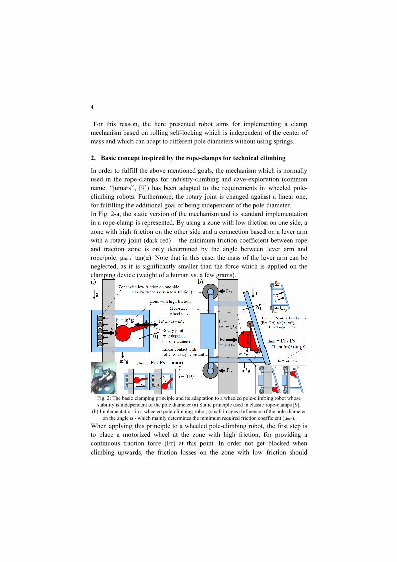
In order to fulfill the above mentioned goals, the mechanism which is normally used in the rope-clamps for industry-climbing and cave-exploration (common name: “jumars”, [9]) has been adapted to the requirements in wheeled pole-climbing robots. Furthermore, the rotary joint is changed against a linear one, for fulfilling the additional goal of being independent of the pole diameter. In Fig. 2-a, the static version of the mechanism and its standard implementation in a rope-clamp is represented. By using a zone with low friction on one side, a zone with high friction on the other side and a connection based on a lever arm with a rotary joint (dark red) – the minimum friction coefficient between rope and traction zone is only determined by the angle between lever arm and rope/pole: µmin=tan(α). Note that in this case, the mass of the lever arm can be neglected, as it is significantly smaller than the force which is applied on the clamping device (weight of a human vs. a few grams).
Fig. 2: The basic clamping principle and its adaptation to a wheeled pole-climbing robot whose stability is independent of the pole diameter (a) Static principle used in classic rope-clamps [9],
(b) Implementation in a wheeled pole-climbing-robot, (small images) Influence of the pole-diameter on the angle α - which mainly determines the minimum required friction coefficient (µmin).
When applying this principle to a wheeled pole-climbing robot, the first step is to place a motorized wheel at the zone with high friction, for providing a continuous traction force (FT) at this point. In order not get blocked when climbing upwards, the friction losses on the zone with low friction should

5
ideally be minimized by using non-motorized wheels there – similar as in other designs of wheeled pole climbing robots. For keeping α independent of the pole diameter, the here presented design uses a linear contact with rolls instead of the rotary joint in the rope clamps. The entire mechanical concept is represented in Fig. 2-b, with the adaptation to different pole diameters drawn in the small picture at the bottom. For calculating the stability against slipping, the mass of the motorized wheel unit (m2) also needs to be taken into account, as strong gear motors usually form a significant part of the robot’s mass – in the case of the designs presented in chapter 3 and 4, this mass is approximately 20% of the total robot mass (including payload). For adjusting the angle α to an optimal value, this additional influence should not be forgotten (µmin=tan(α)*(1+m2/m)).
3. Conceptual design for a pole-climbing robot with high payload
Based on this clamping mechanism, a concept for a pole-climbing robot with high payload capability has been developed – for climbing on palm trees for fruit-harvesting, accessing telephone masts for service tasks or climbing lamp-posts. Concerning its payload capability, it should ideally be strong and safe enough for carrying human workers. With these goals, the specifications were defined as follows: Payload capability 100kg regarding the motor power and 500kg against breaking or slipping; Adaptability to poles from Ø0.2m to Ø0.5m, estimated worst-case friction-coefficient µ=0.5 (rubber-tire on a wet tree), speed above 2m/s, mass without payload below 20kg, supply with 12V DC. Concerning the structure design (see Fig. 3-a), a framework out of rectangular aluminum tubes was chosen, mainly motivated by the easy changeability in case of later adaptations and the relatively small effort for manufacturing. For the passive wheels, standard rolls for pallet-trucks have been considered as a good option. The choice of an appropriate combination for motor, gear and main wheel resulted to be the most difficult part of this work, as the required values for torque and power are very high in this application: Assuming a wheel radius r of approximately 250mm and given the requirements for payload and speed (100kg respectively 1000N; 2m/s) – the motor-gear-combination needs to provide 2kW and 250Nm. When searching in the catalogues for standard gear motors in robotics, actuators in this power-class are already quite difficult to get. For example, at Maxon the upper end of the range is already reached with 400W and 120Nm. In the final prototype, it is planned to combine the motor of an electric car with a customized worm-gear transmission. The detailed design of the drive unit has not started yet because of the relatively high cost of these components.

6
For optimizing the structural design of the frame, FEM-simulations have been performed, using the worst-case-assumption with a total load on the robot of up to 500kg. After some iterations, the thicknesses of the Al-profiles could be optimized to values which assure enough security against breaking (S>2 everywhere) while still keeping the mass below 10kg for the entire frame.
Fig. 3: Detailed design of the robot (a) CAD-drawing of the main components, (b) Collision
analysis on several pole diameters, (c) FEM-analysis to optimize the mass of the frame.
4. Tests with a preliminary prototype at scaled size
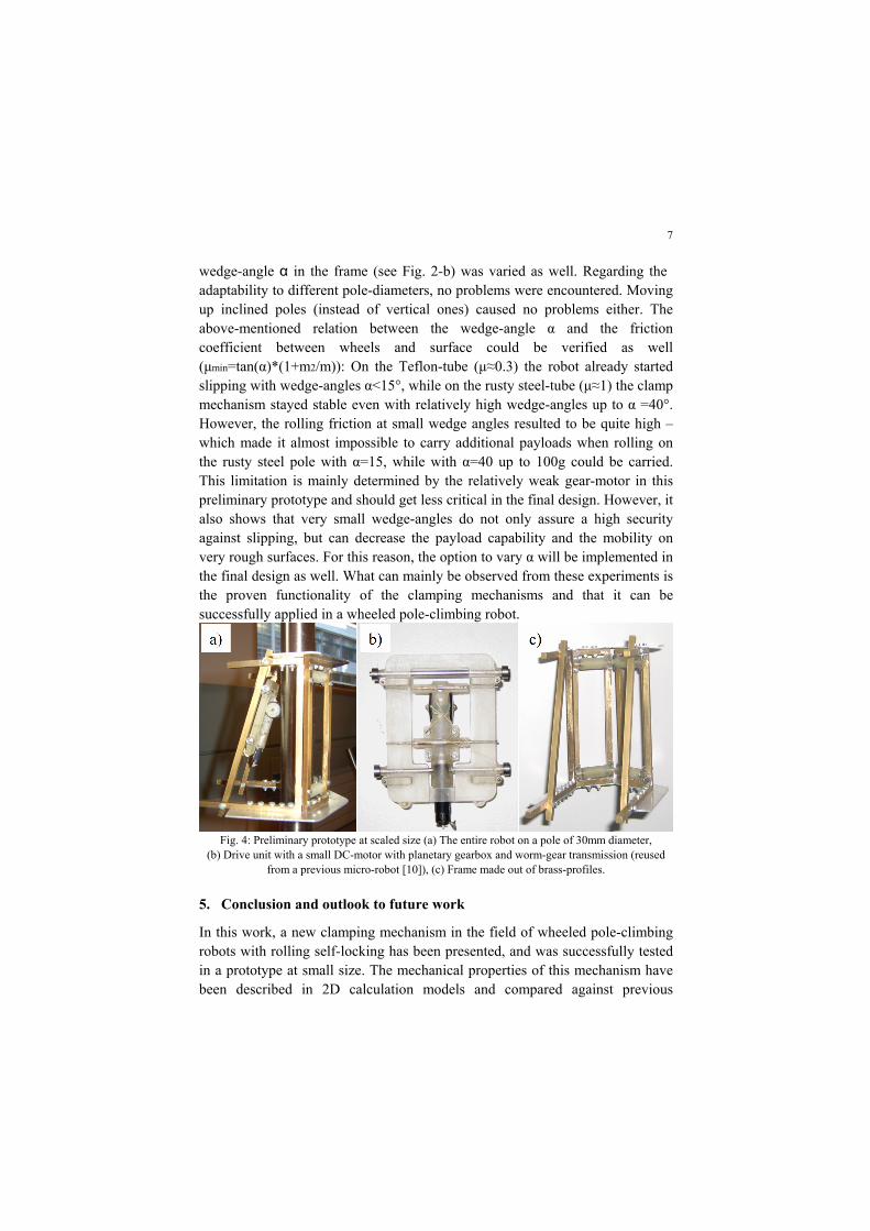
Given the difficulties to purchase the required gears and motors for the drive-unit at a reasonable price and engineering effort, the first tests have been performed with a preliminary prototype at scaled size (1:10). For the structure parts, rectangular solid-profiles out of brass have been used. Concerning the drive units, slightly modified units coming from a previously designed micro-robot for turbine inspection [10] could be reused. Photos of the entire prototype, the frame design and the drive units are shown in Fig. 4. The mass of the drive unit (Fig. 4-b) resulted in 18g, the mass of the frame (Fig. 4-c) in 180g. This prototype was tested on poles with different diameters (Ø20, Ø30, Ø40 and Ø50) and surfaces (Teflon, polished steel, rust-covered steel). Additionally, the
7
wedge-angle α in the frame (see Fig. 2-b) was varied as well. Regarding the adaptability to different pole-diameters, no problems were encountered. Moving up inclined poles (instead of vertical ones) caused no problems either. The above-mentioned relation between the wedge-angle α and the friction coefficient between wheels and surface could be verified as well (µmin=tan(α)*(1+m2/m)): On the Teflon-tube (µ≈0.3) the robot already started slipping with wedge-angles α<15°, while on the rusty steel-tube (µ≈1) the clamp mechanism stayed stable even with relatively high wedge-angles up to α =40°. However, the rolling friction at small wedge angles resulted to be quite high – which made it almost impossible to carry additional payloads when rolling on the rusty steel pole with α=15, while with α=40 up to 100g could be carried. This limitation is mainly determined by the relatively weak gear-motor in this preliminary prototype and should get less critical in the final design. However, it also shows that very small wedge-angles do not only assure a high security against slipping, but can decrease the payload capability and the mobility on very rough surfaces. For this reason, the option to vary α will be implemented in the final design as well. What can mainly be observed from these experiments is the proven functionality of the clamping mechanisms and that it can be successfully applied in a wheeled pole-climbing robot.
Fig. 4: Preliminary prototype at scaled size (a) The entire robot on a pole of 30mm diameter,
(b) Drive unit with a small DC-motor with planetary gearbox and worm-gear transmission (reused from a previous micro-robot [10]), (c) Frame made out of brass-profiles.
5. Conclusion and outlook to future work
In this work, a new clamping mechanism in the field of wheeled pole-climbing robots with rolling self-locking has been presented, and was successfully tested in a prototype at small size. The mechanical properties of this mechanism have been described in 2D calculation models and compared against previous
8
designs. Given the fact that this new clamping mechanism is not dependent on the robot’s center of mass, does not need additional springs, and has the ability for passively adapting to different pole diameters – it brings significant advantages for the design of wheeled pole climbing robots. Future work will focus on the final design of the prototype at big size, which is planned for pole diameters between Ø0.2m and Ø0.5m and high payloads up to 100kg. Concerning this robot, only the dimensioning of the frame has been done until now, while the design of the drive unit will be addressed in the next work packages of this project.
References
1. M. Abderrahim, C. Balaguer, A. Giménez, J. Pastor, V. Padrón, “ROMA: A Climbing Robot for Inspection Operations”, International Conference on Robotics & Automation, ICRA'99, Detroit, USA, May, 1999.
2. J. Maempel, E. Andrada, H. Witte, “INSPIRAT – towards a biologically inspired climbing robot for the inspection of linear structures”, Proc. of the 11th International Conference on Climbing and Walking Robots and the Support Technologies for Mobile Machines (CLAWAR), September 2008.
3. M. Tavakoli, L. Marques, A. de Almeida, "Self Calibration of Step-by-Step Based Climbing Robots”, The 2009 IEEE/RSJ International Conference on Intelligent Robots and Systems, Oc-tober 11-15, 2009.
4. T. Sattar, H.Rodriguez, B. Bridge, “Climbing ring robot for inspection of offshore wind turbines”, Ind. Robot, Vol. 36/4, 326-330, 2009.
5. A. Sadeghi, H. Moradi, M. Ahmadabadi, “Analysis, simulation and implementation of a human inspired pole climbing robot”, Proc. of The 11th International Conference on Climbing and Walking Robots and the Support Technologies for Mobile Machines (CLAWAR), Sept. 2008.
6. J. Fauroux, J. Morillon, “Design of a climbing robot for cylindro-conic poles based on rolling self-locking”, Ind. Robot, Vol. 37/3, 326-330, 2010.
7. S. Kim, A. Asbeck, M. Cutkosky, W. Provancher, “SpinybotII: Climbing Hard Walls with Compliant Microspines”, Int. Conf. On Advanced Robotics, 2005
8. F. Tache, W. Fischer, G. Caprari, R. Moser, F. Mondada, R. Siegwart, "Magnebike: A Magnetic Wheeled Robot with High Mobility for Inspecting Complex Shaped Structures", Journal of Field Robotics, Vol. 26-5, May 2009, 453-476.
9. PETZL, "Professional – rope clamps – rope ascension and hauling”, product information from company webpage, www.petzl.com/en/pro/rope-clamps
10. W. Fischer, G. Caprari, R. Siegwart, I. Thommen, W. Zesch, R. Moser, „Foldable magnetic wheeled climbing robot for the inspection of gas turbines and similar environments with very narrow access holes”, Ind. Robot, Vol. 37, Issue 3, 2010.