research article numerical simulation of interaction
TRANSCRIPT

Research ArticleNumerical Simulation of Interaction between HallThruster CEX Ions and SMART-1 Spacecraft
Kang Shan1 Yuchuan Chu1 Qingyu Li1 Liang Zheng2 and Yong Cao1
1Department of Mechanical Engineering and Automation Harbin Institute of Technology Shenzhen Graduate SchoolShenzhen Guangdong 518055 China2Department of Natural Sciences and Humanities (MathematicsMechanicsHumanities) Harbin Institute of TechnologyShenzhen Graduate School Shenzhen Guangdong 518055 China
Correspondence should be addressed to Yong Cao yongchitszeducn
Received 11 June 2014 Accepted 13 September 2014
Academic Editor Junuthula N Reddy
Copyright copy 2015 Kang Shan et al This is an open access article distributed under the Creative Commons Attribution Licensewhich permits unrestricted use distribution and reproduction in any medium provided the original work is properly cited
The interaction between the plume of Hall thruster and the surface of the SMART-1 spacecraft is investigated by developing a three-dimensional IFE-PIC-MCC code with the emphasis on the effect of the disturbance force and thermal loading caused by chargeexchange ions (CEX) impingement on the surface of the spacecraftThe parameters such as heat flux and forces of CEX ions whichimpinge on SMART-1 and solar arrays are obtained The disturbance force of CEX ions to the spacecraft is calculated for differentdivergence angles and different solar array rotation cases The simulation results show that the disturbance force and heat flux onspacecraft change very little as the divergence angle changes The effect of maximum disturbance force can be neglected since it isso small comparing with the nominal value of the main thrust Solar arrays receive the least thermal heating from the CEX ionswhen the beam ions flow is perpendicular to the solar array plane
1 Introduction
Themotion of the satellite is usually controlled by the ejectionof the plume from the thruster into the space Then theinteraction between the plume and the spacecraft surfacemay cause undesirable effects such as causing the disturbanceforce and thermal loads and contaminating sensitive equip-ment and sensors The disturbance force can be a fractionof the total thrust while thermal loads on the surface ofspacecraft body result in the heating of the surface and affectthe working status of electronic components which can onlyfunction properly in a range of temperatures So the accuratemodeling and predictions of these effects are very crucial tothe design of a satellite [1ndash3]
The interaction between the exhausted plume of thrustersand the satellite components has been studied by someresearchers for both chemical thrusters and electric propul-sions thrusters [2 4] Park et al [2] used three-dimensionaldiscrete simulation Monte Carlo (DSMC) to investigatethe interaction of the chemical thruster (a 445N MRE-1
monopropellant hydrazine liquid rocket engine) plume withsatellite components in KOMPSAT-II The results showeda negligible disturbance forcetorque and thermal loadingcompared with its nominal thrusttorque and solar heatingXiao et al [5] analyzed molecules adsorption and transmis-sion on the surface of satellite by using numerical simulationand ground experiment method Also the motion of plumepollutantswhich leads to performance degradation of satellitekey functional surfaces (optical systems solar panels thermalcontrol object surface etc) is calculated Different fromthe plume of the chemical thrusters the plume of electricpropulsion is plasma which consists of a large number ofions and electrons except neutral atoms In addition chargeexchange collisions will occur between the high-speed ionsand neutral atoms which result in the generation of low-speed CEX ions that have significant impact on the plumecharacteristicsThese charged particles are affected heavily bytheir self-consistent electric fields Therefore compared withthe plume of the chemical thrusters the plume of the electricpropulsion thruster is different in not only the ingredients
Hindawi Publishing CorporationMathematical Problems in EngineeringVolume 2015 Article ID 418493 8 pageshttpdxdoiorg1011552015418493
2 Mathematical Problems in Engineering
of the plume but also the flow characteristics of the plumeA number of simulation models or numerical methods havebeen developed for the plume in the electric propulsionthruster to investigate the interaction with the spacecraftsurface and the results from these numerical models wereverified through the comparison with the experiment datain recent years [6ndash13] Yan et al [10] used particle in cell(PIC) code with DSMC techniques to model Hall thrusterplume and sputtering erosion on SPT-70 Kafafy and Cao[11] investigated plume effects from indirect plume impinge-ment on formation flying satellites using ion propulsionby developing an immersed-finite-element PIC (IFE-PIC)algorithm on parallel computers Tajmar et al [12] developeda hybrid PIC code with Monte Carlo collision (MCC) tostudy spacecraft-environment interaction Boyd [13] studiedthe ion current density profile and ion energy distributionby using a detailed particle-fluid PIC-DSMC model whichwas compared with the experimental measurements taken inspace However most of them were concerned about CEXions sputtering erosion or the accuracy of simulation modelbut few of them were concerned about the disturbance forceand thermal loading on the spacecraft which are caused bythe impinging of the backflow CEX ions on the surface of thespacecraft
Therefore in this paper the study of the force andthermal loads on the spacecraft caused by backflow CEXions is performed by using a three-dimensional IFE-PIC-MCC code The PIC-MCC [12] code is used to simulate thegeneration and movement of CEX ions The DSMC method[14] is applied to model neutral atoms Electric field in theplume is obtained by solving Poissonrsquos equation which iscalculated by IFE-PIC [15 16] method which is designedto handle complex boundary conditions accurately whilemaintaining the computational speed of the standard PICcode The code is then applied to the numerical simulationsof the SMART-1 spacecraft which had traveled to the moonusing a PPS-1350 Hall thruster with the maximum thrust of70mN [17]
Section 2 describes the interaction model between theplume of Hall thruster and the surface of the spacecraft Thenumerical method is presented in Section 3 The simulationresults are then shown in Section 4 and some discussionson these results are carried out Finally the summary andconclusions are presented at the end of this paper
2 SMART-1 Spacecraft-PlumeInteractions Model
The geometry and dimensions of SMART-1 spacecraft modelare illustrated in Figure 1 The main body of SMART-1 canbe considered as the cubic shape with the dimensions of 119897 times119908 times ℎ = 1100mm times 1100mm times 900mm In this model theHall thruster is simplified as a cylinder with the diameter of100mm and the height of 50mm two thin rectangles with5400mm length and 1000mmwidth are utilized to representthe solar arrays which can rotate around the satellite
The PPS-1350 Hall thruster emits an ion beam out ofa ring-shaped anode with a divergence angle 120579 = 45
∘Typical operating parameters of PPS-1350 Hall thruster are
D100
1100
1100
100
900
5400
1000
D100
100
100
990000
Figure 1 The geometry and dimensions of SMART-1 (in mm)
Table 1 Operating parameters of PPS-1350 Hall thruster
Parameter ValueThrust 70mNVoltage 119880acc 350VIon current 119868
119894
38 AMass flow rate 42mgsSpecific impulse 164 sTotal efficiency 120578 51Outer insulator diameter 119903
119900
100mmInner insulator diameter 119903
119894
56mmNeutral temperature 750KElectron temperature 119879
119890
2 eV
summarized in Table 1 [13] At the exit of the thrusterthe densities and temperatures are assumed to be radicallyuniform and the velocity vectors vary uniformly from minus45
∘
at the lower edge of the channel exit to +45∘ at the upper
edge The temperatures of the electrons and neutrals areassumed to be 2 eV and 750K respectivelyThe heavy particledensities and velocities are subsequently obtained from themass flow rate and integrated ion current The plume in thePPS-1350 Hall thruster assumingly consists of the followingcomponents
(i) propellant beam ions(ii) unionized propellant neutrals(iii) slow propellant ions created by CEX reaction colli-
sions(iv) neutralising electrons
The plasma in the beam of the Hall thruster typicallyhas a number density of more than 10
15mminus3 The widelyused PIC approach is applied in this research The so-calledsuper particle representing a number of 109 real particles isintroduced here As a result the total number of simulatedentities of Xe and Xe+ is kept below 10
7 therefore thesimulations can be carried out on standard workstations [17]
Xe+ particles are given a constant velocity at the thrusterexit as
V119894= radic
2119890119880acc119898119894
(1)
Mathematical Problems in Engineering 3
where 119880acc is accelerating voltage 119898119894 is xenon ion mass andV119894denotes the ion velocityInitially the ions are uniformly distributed across the
thruster opening between the inner radius 119903119894and the outer
radius 119903119900 The direction of the velocity v
119894is determined in
spherical coordinates (V119894 1205721 1205722) [17] where 120572
1is randomly
chosen in 0 lt 1205721lt 2120587 and 120572
2is varied in accordance with the
radial position between the inner and outer beam-spreadingangles 120572
119894and 120572
119900by
1205722(119903) =
120572119900minus 120572119894
119903119900minus 119903119894
(119903 minus 119903119894) + 120572119894 (2)
where 119903119900and 119903119894are the outer and inner radii at the exit of the
thruster respectivelyDuring the simulations the number of ejected Xe+ beam
ions by the Hall thruster at each time-step is obtained by theion current
Δ119899119894= 119868119894Δ119905 (3)
where 119868119894denotes ion currentΔ119899
119894is number of ions generated
at each time step and Δ119905 represents the time of each stepThe electrons are assumed to be collisionless currentless
isothermal and unmagnetized The plasma is quasineutraland electrons satisfy the Boltzmann [12] relation as
119899119890= 1198991198900exp[
119890 (120601 minus 1206010)
1198961198791198900
] (4)
where 119899119890is electron number density 120601 is potential and 119899
1198900
1206010represent the reference parametersThe electric field surrounding the spacecraft is solved
from Poisson equation
minusnabla sdot 120576nabla120601 = 119890 (119899119894minus 119899119890) (5)
where 120576 denotes permittivity of vacuum 119899119890is electron
number density 119899119894represents ion number density and 120601 is
the potentialCharged particles in the simulation area are accelerated
due to the electric field Their movement can be determinedby the integration of the equation of motion which can bedescribed with Newtonrsquos second law
dd119905
(119898v) = F = 119902E v =dxd119905
(6)
Neutral Xe propellant atoms are introduced with no driftvelocity but the thermal velocity related to the temperatureof the neutral Xe propellant atom As neutral Xe atomsmove the DSMC method is applied to simulate collisions ofneutral Xe propellant atoms since neutral propellant can beconsidered as a rarefied gas flow In this method each unitcell containing many particles has the dimensions on theorder of a mean free path Pairs of these particles are thenrandomly selected and a collision probability is evaluatedwhich is proportional to the product of the relative velocityand cross section of the collision for each pairThe probabilityis compared with a random number to determine if thatcollision occurs
Let us consider a single simulation cell containing anumber of simulation macroparticles Bird [14] gives theprobability of a collision for a macroparticle in this cell
119875 = 119865119873120590119879119888119903
Δ119905
119881119888
(7)
where 119865119873is the macroparticle weight 120590
119879is the total collision
cross section 119888119903is the relative velocity Δ119905 is the simulation
time step and 119881119888is the cell volume
One order to check for collisions would be to iterate overall 119873 particles and compute probability with all remainingparticlesThis would result in119873(119873minus1)2 sim (119873
2
)2 pairs Fora large number of particles this method clearly becomes verycomputationally inefficient Birdrsquos no time counter (NTC)methodwas designed to provide help with this issue It allowsus to estimate ahead of time the maximum number of pairsthat need to be checked The maximum collision probabilityis
119875max = 119865119873
(120590119879119888119903)max
Δ119905
119881119888
(8)
where (120590119879119888119903)max is a parameter chosen ahead of time using
approximate predictions of cross section and velocity AsBird points out in his book the actual value is not all thatimportant since it ends up getting cancelled outThe numberof pairs to check is then
(1
2)119873119873119865
119873(120590119879119888119903)max
Δ119905
119881119888
(9)
Here the second 119873 is the average particle count The aver-age is used to reduce the statistical time-step to time-steposcillations For each pair we then compute the probabilityas follows
119875 =120590119879119888119903
(120590119879119888119903)max
(10)
This value is compared to a random number and the collisionoccurs if 119875 gt 119877
For atom-atom elastic collisions the variable hard spherecollision model is employed For xenon the collision crosssection is
120590EL (XeXe) =212 times 10
minus18
1198922120596m2 (11)
where 119892 is the relative velocity and 120596 denotes the viscositytemperature exponent for xenon which has the value of 012[14]
Charge-exchange collisions occur between the fast beamXe+ ions and the slow neutral Xe atoms After these collisionsthe fast beam Xe+ ions turn to be neutral and keep the fastspeed and the slow neutral Xe atoms change into ions whichare accelerated due to the effect of the electric field Thesechanges can be expressed as follows
Xeslow + Xe+fast 997888rarr Xe+slow + Xefast (12)
4 Mathematical Problems in Engineering
To model the CEX process we use the MCC methodFor each Xe+ ion we calculate the collision probability Thisprobability is then compared to a random number If theprobability is larger than the random number the collisionoccurs and a process-specific collision handler is called Thecollision probability is given by Birdsall [18] as
119875 = 1 minus exp (minus]Δ119905) = 1 minus exp (minus119899119899120590119892Δ119905) (13)
119899119899is the density of the target gas at the location of the particle
120590 is the collision cross section 119892 is the relative velocity andΔ119905 is the time difference between collision checks This time-step may correspond to the time-step used to move the ionsin the PIC method
In this research the transfer of only one electron betweenan atom and an ion is considered during the charge-exchangeprocess For singly charged ions the following cross sectionmeasured by Pullins et al and Miller et al [19 20] is used
120590CEX (XeXe+) = [minus2330log10
(119892) + 14221] times 08423
times 10minus20m2
(14)
where 119892 is the relative velocity between the beam ion andneutral atom
Boundary conditions for computing of the Hall thrusterplume are presented as follows Both field and particleboundary conditions are required at the outer boundary ofthe computational domain The field condition is simply setas the electric field normal to the boundary edges equal tozero The particle boundary condition is set to be that anyparticle crossing the boundary is simply removed and will nolonger be calculated in the model The solid surfaces of theHall thruster and the satellite are also considered during thesimulations Along these surfaces the potential of surfaces isset to be at a certain given value (minus2V) Any ions collidingonto the surfaces are absorbed by the surfaces
3 Numerical Method
A particle simulation code using the IFE-PIC-MCC algo-rithm is developed to solve the plume interaction problemThe IFE-PIC-MCC code solves the generating of CEX ionsand their trajectories and the electric field surrounding thespacecraft
The simulation is run in three phases modeling beamXe+ ions neutral Xe and CEX ions respectively The reasonthat these different species particles can be simulated asyn-chronously is as follows
(1) Beam Xe+ ions have so high energy that they arehardly affected by self-consistent electric field
(2) Neutral Xe atoms do not get charged so that they arenot affected by electric field
(3) CEX ions are in small numbers in plasma plume andtheir generation affects the plume character very little
In the first phase we run the PIC code to generateand trace beam Xe+ ions and neutral Xe until steady-state
Z
Y
X
4m
1m
O4m
75m
Figure 2 The dimensions of the simulation region
trajectories are obtained In this phase we use a simplifiedapproach to model beam Xe+ ions Those beam Xe+ ions areaccelerated in the Hall thruster channel with the velocities onthe order of 10 kms So most high-energy beam Xe+ ions areunaffected by self-consistent electric field and follow straighttrajectories The DSMC method is used in the computationof Xe-Xe collisions After this phase the distribution of beamXe+ ions and neutral Xe is gotten in the computation regionrespectively
In the second phase the IFE-PIC-MCC code is used totrace CEX ions until steady-state trajectories are obtainedCEX ions are generated from the collision of steady-statebeam Xe+ ions and neutral Xe by MCC at each time stepThe initial velocity of CEX ions is given a uniform velocitydistribution with a temperature corresponding to that of theneutral propellant That is to say initial CEX ions only havethermal velocity with no drift velocity which is relativelysmall and is affected heavily by electric field Using IFE-PICthe electric field is calculated which pushes the movement ofCEX ions at each time step Those processes are cycled untilsteady-state CEX ions trajectories are obtained
In the final phase CEX ions are collected which impingeon SAMRT-1 and solar arrays then all those CEX ions areused to calculate the flux density of CEX ions the energydistribution and pressure distribution on SMART-1 and solararrays
4 Simulations Results
Due to the symmetry of SMART-1 (as illustrated in Figure 1) ahalf-symmetrymodel is employed to simulate the interactionbetween the plume and the surface of SMART-1 as shown inFigure 2 The position of SMART-1 in the simulation regionis also shown in Figure 2The simulation domain has a size of40m times 75m times 40mwith 81 times 151 times 81 grid points Duringthe simulations approximately 8 million simulation particlesare employed The time-step is on the order of 10
minus6 s Thesimulation reaches a steady state for CEX ions after about 800iterations and solutions are then averaged over further 200
Mathematical Problems in Engineering 5
20 40 60 800
20
40
60
805000
4222
3444
2667
1889
1111
333
(V)
z
x
minus2000
minus1222
minus444
(a)
y
0 50 100 1500
20
40
60
80
z (V)
500042223444266718891111333
minus2000minus1222minus444
(b)
Figure 3 Plasma potential distribution (at 120579 = 45∘ 120574 = 0
∘)
iterationsThe total computation time is about 24 h on an HPcomputer server
Figure 3 illustrates the distribution of the potential underthe conditions of 120579 = 45
∘ and 120574 = 0∘ (here 120574 is the angle
between the normal of the solar array plane and the centerline of the beam flow) As shown in Figure 3 the backflowof the CEX ions results in the fact that the isopotentialsurface expands toward a direction opposite to the ion beammovement It makes the pattern of the distribution look likea mushroom
Figures 4 and 5 present the pressure and energy distribu-tion of CEX ions on solar arrays respectively As solar arrayscan rotate around the axis to change their direction the effectof the angle between the normal of solar array plane and thebeam flow c enter line is investigated As illustrated in Figures4 and 5 three different angles are chosen as 120574 = 0
∘ 45∘and 90
∘ and their effects are presented It is clear to see thatthe solar arrays receive more CEX ions and bear much morepressure at 120574 = 0
∘ than at 120574 = 90∘
Figures 6 and 7 present the energy and pressure distribu-tion about CEX ions impinging on the surface of SMART-1 main body CEX impingement on main body and CEXions distribution on main body are almost the same fordifferent solar array rotation angles since different solar arraypositions can hardly affect the electric field distribution in
Table 2 Parameter values on main body for different solar arrayrotation angle cases (at 120579 = 45
∘)
Solar array rotationangle 120574 (in deg)
Average energy(in Wm2)
Disturbance normalforce (in mN)
0 246513 0565245 246513 0565290 246513 05652
the vicinity of the main body Also it can be observed thatthe less backflowCEX ions on themain body can be obtainedalong with the increasing of the distance to the location oftheHall thrusterThemaximum energy of CEX ions reachingonto the main body of the spacecraft is 17056Wm2
Tables 2 and 3 list the values of the disturbance normalforce and thermal loading on the SMART-1 spacecraft fordifferent solar array rotation angle cases which are calculatedbased on the backflow CEX ions energy and pressure distri-bution It can be seen that the values of the average energyand disturbance force on the main body of the spacecraft arethe same under different solar array rotation angle while thevalues of the average energy and disturbance force on solararrays decrease as the solar array rotation angle 120574 increasesThe maximum value of disturbance force onto spacecraft canreach 07mN when 120574 = 0
∘ The tangential force acting on themain body is symmetric due to the symmetric distributionof the pressure on the main body (as shown in Figure 7)Although tangential force on the half main body can reacha value of 01512mN the total tangential force on mainbody is counteracted and can be neglected As the rotationangle of the solar array increases the tangential force in thedirection of array plane length direction decreases due to lessCEX impingement on solar arrays But the total effect of thetangential force on the solar arrays is limited since the totaltangential force on both solar arrays is mostly counteractedwith each other
Figure 8 presents the distribution of the plasma potentialfor different divergence angle It can be seen in Figure 8 thatthe distributions of the plasma potential are quite differentunder the condition of the same rotating angle but differentdivergence angle The divergence angle also affects the CEXions impinging on the spacecraftThe effects of three differentdivergence angles are studied for the same mass flow rate(42mgs) The solar arrays are set in the position that solararrays are perpendicular to ion beam (120574 = 0
∘) and theparameters of CEX ions impingement are recorded for thethree divergence angles 120579 = 15
∘ 30∘ and 45∘
As listed in Table 4 the average energy on both themain body and solar arrays does not change much when thedivergence angle changes As divergence angle increases thedisturbance force on the main body increases very little Thedisturbance force to solar arrays is relatively small comparingto the disturbance force on the main body since solar arraysare far from the flux beam flow and receive less CEX ionsThemaximum disturbance force is less than 01 of the nominalvalue of the main thrustThus the disturbance force has littleinfluence on the dynamic system of the satellite as well as thepropellant budget
6 Mathematical Problems in Engineering
(a) 120574 = 0∘ (b) 120574 = 45∘
116 times 10minus04
625 times 10minus05
336 times 10minus05
181 times 10minus05
975 times 10minus06
525 times 10minus06
283 times 10minus06
820 times 10minus07
442 times 10minus07
238 times 10minus07
128 times 10minus07
690 times 10minus08
371 times 10minus08
200 times 10minus08
152 times 10minus06
(c) 120574 = 90∘
Figure 4 Pressure distribution of CEX ions on the solar array of SMART-1 (at 120579 = 45∘) (in Nm2)
(a) 120574 = 0∘ (b) 120574 = 45∘
148 times 10+00
744 times 10minus01
375 times 10minus01
189 times 10minus01
950 times 10minus02
479 times 10minus02
241 times 10minus02
121 times 10minus02
612 times 10minus03
308 times 10minus03
155 times 10minus03
782 times 10minus04
394 times 10minus04
199 times 10minus04
100 times 10minus04
(c) 120574 = 90∘
Figure 5 Energy distribution of CEX ions on the solar array of SMART-1 (at 120579 = 45∘) (in Wm2)
30 35 40 45 500
2
4
6
8
10
x
y
764 times 10+00
153 times 10+00
308 times 10minus01
617 times 10minus02
124 times 10minus02
248 times 10minus03
498 times 10minus04
100 times 10minus04
Figure 6 CEX ions energy distribution on the surface of SMART-1 main body (at 120579 = 45∘) (in Wm2)
Mathematical Problems in Engineering 7
Table 3 Parameter values on one of solar arrays for different solar array rotation angle cases (at 120579 = 45∘)
Solar array rotationangle 120574 (in deg)
Average energy(in Wm2)
Disturbance normalforce (in mN)
Tangential force in arraywidth direction (in mN)
Tangential force in arraylength direction (in mN)
0 016692 009449 0 0207145 012463 005512 00354 0156290 002903 001105 000732 00748
Table 4 Parameter values for different divergence angle cases (at 120574 = 0∘)
Divergenceangle 120579 (in deg)
Average energy onmain body (in Wm2)
Average energy on solararrays (in Wm2)
Disturbance force tomain body (in mN)
Disturbance force tosolar arrays (in mN)
15 243187 018829 054366 01731730 242073 019279 054532 01948345 246513 016692 056523 018897
30 35 40 45 500
2
4
6
8
10
y
x
100 times 10minus02
213 times 10minus03
454 times 10minus04
969 times 10minus05
206 times 10minus05
440 times 10minus06
938 times 10minus07
200 times 10minus07
Figure 7 CEX ions pressure distribution on the surface of SMART-1main body (at 120579 = 45
∘) (in Nm2)
0 50 100 1500
20
40
60
80
y
z
333111118892667344442225000
(V)
minus444minus1222minus2000
(a) At 120579 = 15∘ 120574 = 0∘
y
z
0 50 100 1500
20
40
60
80
333111118892667344442225000
(V)
minus444minus1222minus2000
(b) At 120579 = 45∘ 120574 = 0∘
Figure 8 Distribution of plasma potential for different divergenceangles
5 Summary and Conclusion
In summary the interaction between the plume of theHall thruster and the SMART-1 spacecraft has been inves-tigated using a three-dimensional IFE-PIC-MCC code Inthis research the backflow CEX ions impingement on theSMART-1 is investigated and the effects of the disturbanceforce and the thermal loading due to the impingement arestudied The effects of different divergence angles and solararray rotation angles on the disturbance force are consideredSimulation results revealed that the maximum disturbancenormal force can only reach a value of 07mN which isrelatively small comparing with the main thrust (70mN) Asthe solar array rotation angle increases both the disturbanceforce on the spacecraft and the average energy on solar arraysdecrease substantially With the increment of the divergenceangle both the disturbance force and the average energy onthe surface of spacecraft are slightly changed under the samesolar array rotation angle conditions whereas the disturbanceforce in the main body has a slight rise But the maximumdisturbance force is less than 01 of the nominal value of themain thrust which means the effect of the disturbance forcecan be ignored
Conflict of Interests
The authors declare that there is no conflict of interestsregarding the publication of this paper
Acknowledgment
This work was supported by the National Natural ScienceFoundation of China under Contract nos 10875034 11175052and 11275034
References
[1] I D Boyd and J P W Stark ldquoModeling of a small hydrazinethruster plume in the transition flow regimerdquo Journal of Propul-sion and Power vol 6 no 2 pp 121ndash126 1990
8 Mathematical Problems in Engineering
[2] J H Park S W Back and J S Kim ldquoDirect simulation MonteCarlo analysis of thruster plumessatellite base region interac-tionrdquo AIAA Journal vol 42 no 8 pp 1622ndash1632 2004
[3] I D Boyd and A Ketsdever ldquoInteractions between spacecraftand thruster plumesrdquo Journal of Spacecraft and Rockets vol 38no 3 p 380 2001
[4] F E Lumpkin III J Marichalar and B D Stewart ldquoHigh fidelitysimulations of plume impingement to the international spacestationrdquo in Proceedings of the 33rd JANNAF Exhaust Plumeand Signatures Subcommittee Meeting Monterey Calif USADecember 2012
[5] Z-J Xiao H-E Cheng and H-L Zhou ldquoPlume interactionin parallel multi-thrusters propulsion system and the effecton backflowrdquo in Proceedings of the 9th AIAAASME JointThermophysics andHeat Transfer Conference pp 1963ndash1972 SanFrancisco Calif USA June 2006
[6] G Markelov and E Gengembre ldquoModeling of plasma flowaround SMART-1 spacecraftrdquo IEEE Transactions on PlasmaScience vol 34 no 5 pp 2166ndash2175 2006
[7] I D Boyd and J T Yim ldquoModeling of the near field plume of aHall thrusterrdquo Journal of Applied Physics vol 95 no 9 pp 4575ndash4584 2004
[8] A Passaro A Vicini F Nania and L Biagioni ldquoNumericalrebuilding of smart-1 plasma plumespacecraft interactionrdquoIEPC Paper IEPC-2005-174 2005
[9] V A S Y A Bondar ldquoModeling of plume of stationary plasmathruster by particle methodrdquo Thermophysics and Aeromechan-ics vol 38 no 3 pp 373ndash392 2001
[10] L Yan P-Y Wang Y-H Ou and X-L Kang ldquoNumericalstudy of hall thruster plume and sputtering erosionrdquo Journalof Applied Mathematics vol 2012 Article ID 327021 16 pages2012
[11] R Kafafy and Y Cao ldquoModelling ion propulsion plume interac-tions with spacecraft in formation flightrdquo Aeronautical Journalvol 114 no 1157 pp 417ndash426 2010
[12] M Tajmar J Gonzalez andAHilgers ldquoModeling of spacecraft-environment interactions on SMART-1rdquo Journal of Spacecraftand Rockets vol 38 no 3 pp 393ndash399 2001
[13] I D Boyd ldquoNumerical simulation of hall thruster plasmaplumes in spacerdquo IEEE Transactions on Plasma Science vol 34no 5 pp 2140ndash2147 2006
[14] G A Bird Molecular Gas Dynamics and the Direct Simulationof Gas Flows Oxford University Press Oxford UK 1994
[15] R Kafafy T Lin Y Lin and J Wang ldquoThree-dimensionalimmersed finite element methods for electric field simulationin composite materialsrdquo International Journal for NumericalMethods in Engineering vol 64 no 7 pp 940ndash972 2005
[16] J Wang Y Cao R Kafafy J Pierru and V K Decyk ldquoSimula-tions of ion thruster plume-spacecraft interactions on parallelsupercomputerrdquo IEEE Transactions on Plasma Science vol 34no 5 pp 2148ndash2158 2006
[17] M Tajmar R Sedmik and C Scharlemann ldquoNumerical simu-lation of SMART-1 Hall-thruster plasma interactionsrdquo Journalof Propulsion and Power vol 25 no 6 pp 1178ndash1188 2009
[18] C K Birdsall ldquoParticle-in-cell charged-particle simulationsplus Monte Carlo collisions with neutral atoms PIC-MCCrdquoIEEE Transactions on Plasma Science vol 19 no 2 pp 65ndash851991
[19] S Pullins R Dressler Y Chiu and D Levandier ldquoThrustersXe+ + Xe symmetric charge transferrdquo in Proceedings of the 38thAIAA Aerospace Sciences Meeting and Exhibit Reno Nev USAJanuary 2000
[20] J S Miller S H Pullins D J Levandier Y-H Chiu and R ADressler ldquoXenon charge exchange cross sections for electro-static thruster modelsrdquo Journal of Applied Physics vol 91 no3 pp 984ndash991 2002
Submit your manuscripts athttpwwwhindawicom
Hindawi Publishing Corporationhttpwwwhindawicom Volume 2014
MathematicsJournal of
Hindawi Publishing Corporationhttpwwwhindawicom Volume 2014
Mathematical Problems in Engineering
Hindawi Publishing Corporationhttpwwwhindawicom
Differential EquationsInternational Journal of
Volume 2014
Applied MathematicsJournal of
Hindawi Publishing Corporationhttpwwwhindawicom Volume 2014
Probability and StatisticsHindawi Publishing Corporationhttpwwwhindawicom Volume 2014
Journal of
Hindawi Publishing Corporationhttpwwwhindawicom Volume 2014
Mathematical PhysicsAdvances in
Complex AnalysisJournal of
Hindawi Publishing Corporationhttpwwwhindawicom Volume 2014
OptimizationJournal of
Hindawi Publishing Corporationhttpwwwhindawicom Volume 2014
CombinatoricsHindawi Publishing Corporationhttpwwwhindawicom Volume 2014
International Journal of
Hindawi Publishing Corporationhttpwwwhindawicom Volume 2014
Operations ResearchAdvances in
Journal of
Hindawi Publishing Corporationhttpwwwhindawicom Volume 2014
Function Spaces
Abstract and Applied AnalysisHindawi Publishing Corporationhttpwwwhindawicom Volume 2014
International Journal of Mathematics and Mathematical Sciences
Hindawi Publishing Corporationhttpwwwhindawicom Volume 2014
The Scientific World JournalHindawi Publishing Corporation httpwwwhindawicom Volume 2014
Hindawi Publishing Corporationhttpwwwhindawicom Volume 2014
Algebra
Discrete Dynamics in Nature and Society
Hindawi Publishing Corporationhttpwwwhindawicom Volume 2014
Hindawi Publishing Corporationhttpwwwhindawicom Volume 2014
Decision SciencesAdvances in
Discrete MathematicsJournal of
Hindawi Publishing Corporationhttpwwwhindawicom
Volume 2014 Hindawi Publishing Corporationhttpwwwhindawicom Volume 2014
Stochastic AnalysisInternational Journal of
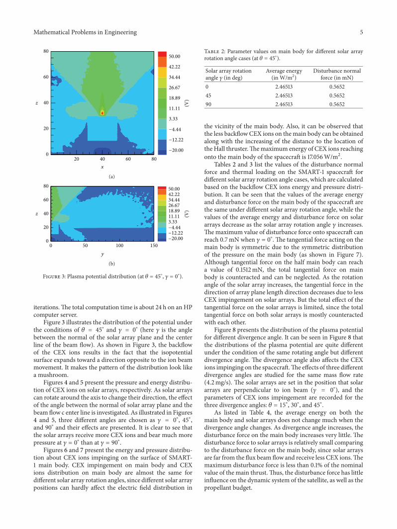
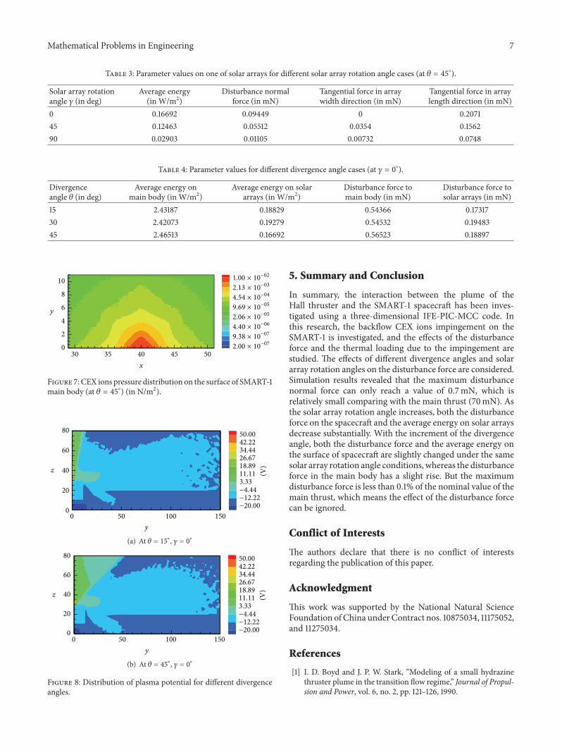