research article nlos path loss model for low-height
TRANSCRIPT

Research ArticleNLOS Path Loss Model for Low-Height Antenna Links inHigh-Rise Urban Street Grid Environments
Juyul Lee Myung-Don Kim Hyun Kyu Chung and Jinup Kim
Wireless Research Department Electronics and Telecommunications Research Institute (ETRI) Daejeon 305-350 Republic of Korea
Correspondence should be addressed to Juyul Lee juyuletrirekr
Received 12 October 2014 Revised 21 January 2015 Accepted 28 January 2015
Academic Editor Alexei Ashikhmin
Copyright copy 2015 Juyul Lee et alThis is an open access article distributed under the Creative CommonsAttribution License whichpermits unrestricted use distribution and reproduction in any medium provided the original work is properly cited
This paper presents a NLOS (non-line-of-sight) path loss model for low-height antenna links in rectangular street grids to accountfor typical D2D (device-to-device) communication link situations in high-rise urban outdoor environments From widebandpropagation channel measurements collected in Seoul City at 37 GHz we observed distinctive power delay profile behaviorsbetween 1-Turn and 2-Turn NLOS links the 2-Turn NLOS has a wider delay spread This can be explained by employing the ideathat the 2-Turn NLOS has multiple propagation paths along the various street roads from TX to RX whereas the 1-Turn NLOShas a single dominant propagation path from TX to RX Considering this we develop a path loss model encompassing 1-Turn and2-Turn NLOS links with separate scattering and diffraction parameters for the first and the second corners based on the UniformGeometricalTheory ofDiffraction In addition we consider the effect of building heights on path loss by incorporating an adjustableldquowaveguide effectrdquo parameter that is higher building alleys provide better propagation environments When compared with fieldmeasurements the predictions are in agreement
1 Introduction
Device-to-device (D2D) communication is increasinglybeing discussed as an emerging mobile technology and itsimportance is expanding as a solution to the challengeof increasing areal capacity as well as supporting disastersituation communications [1 2] From the perspective ofradiowave propagation this technology involves new propa-gation behaviors for mobile communications since the heightof transmitters (eg base stations) is transitioning to nearground levels for typical outdoor D2D uses in urban areasThis leads to more interaction with objects in the closeneighbor surroundings [3] Specifically in high-rise buildingenvironments radiowaves from low-antenna terminals rarelypropagate over-rooftop paths via diffraction but do propa-gate along the street roads [4] Consequently propagationbetween low-antenna terminals in high-rise urban streetinvolves different NLOS (non-line-of-sight) behaviors withldquocornersrdquo in street grids acting as the shadowing objects forNLOS conditions Furthermore the number of corner turnsin propagation paths is an important parameter for NLOSpropagation behaviors
In this paper we develop a NLOS path loss model forlow-height terminals in high-rise urban street environmentsin which corner-turning propagation paths along the streetgrids involve the NLOS situations We will focus on the pathloss prediction model for 1-Turn and 2-Turn NLOS linksAny two locations in regular grids can be reached via upto two corner turns Thus considering 1-Turn NLOS and 2-Turn NLOS are enough to describe the path loss propagationin street grids which will be later clarified Based on theUniform Geometrical Theory of Diffraction (UTD) [5] wederive the path loss predictions with the corner-turningeffects which include LOS-like propagation (eg free spacepath loss) behaviors along the entire propagation path fromTX to RX
By investigating the power delay profile from widebandchannel measurements collected in high-rise urban streetswe observed pronounced differences in the characteristicsof 1-Turn and 2-Turn NLOS links In particular the 2-TurnNLOS has a wider delay spread To explain this phenomenonwe develop a path loss model for 2-Turn NLOS linksseparately from that for 1-Turn NLOS links Building upon
Hindawi Publishing CorporationInternational Journal of Antennas and PropagationVolume 2015 Article ID 651438 9 pageshttpdxdoiorg1011552015651438
2 International Journal of Antennas and Propagation
Lu et alrsquos corner-turning path loss models [6] we derivea path loss model considering separate behaviors of 1-Turnand 2-Turn NLOS links Additionally we refine the freespace path loss model not only for LOS propagation butalso for NLOS propagation with an adjustable parameterfor waveguide effects Note that depending on the sky-lineof cities propagation behaviors vary due to the waveguideeffects for example higher buildings in Street Canyonsprovide better propagation environments [7]
To validate the path loss model we conducted measure-ment campaigns in Seoul City at 37 GHz with a 20MHzbandwidth The predictions with the path loss model are inagreement with the measured data Although the proposedpath loss model has a relatively simple form it does providereasonably accurate predictions for propagation behaviorbetween low-height terminals in high-rise environmentsFrom the perspective of the wireless system design andevaluation process for D2D communications we expect thatthis new model will expedite by simplification the ability toestimate radiowave coverage amount of interference radioresource management and so on
Prior Work There has been a considerable amount of priorwork on path loss characteristics for urban street environ-ments Xia et al [8] investigated the dependency of path losson base station antenna height for urban NLOS propagationsituations Nagata et al [9] found out that reflection by build-ing walls is one of the dominant propagation mechanismsWith a ray tracing technique assuming that reflection bybuilding walls is dominant Erceg et al [10] developed a pathloss model in which the corner loss is characterized witha sudden drop and a steep slope change By adding effectsof diffraction Erceg et al [11] elaborated the path loss atcorners with the UniformGeometricalTheory of DiffractionMolisch et al [12] also considered a geometrical approach byintroducing a local scatter model around mobile terminalsThis approach was further investigated by Sun et al [13]to combine both geometrical ray reflection and diffractiontheories whichwas then extended to consider a 2-turn cornerloss as well Similarly S Y Tan andH S Tan [14] investigatedthe path loss behaviors at corners with diffraction and reflec-tion mechanisms with an image concept Berg [15] deviseda recursive method to calculate path loss due to multiplediffractions at corners Andersen et al [16] analyzed thatreflection scattering and diffraction are street propagationmechanism in urban building environments All of theseeffects on radio propagation in urban street environmentshave been summarized in ITU-R (International Telecommu-nication Union Radiocommunication Sector) standards [17]which have been successful for planning and evaluations inldquoconventionalrdquo mobile communication system designs
As an example Figure 1 illustrates a path loss measure-ment data in which both LOS and NLOS path loss dataare in well agreement with the ITU-R P1411 Street Canyonpath loss model The measurement was collected in an urbanstreet grid area as shown in Figure 1(a) where TX was heldat a stationary position (998779) while RX was moving along the998779 rarr ⃝ rarr ◻ route Note that a LOS link is estab-lished from TX to RX when RX is the measurement interval
998779 rarr ⃝ while a NLOS link is established when RX isin ⃝ rarr ◻ (a LOS link can be also established for someinterval right after ⃝ due to wide corner areas) Duringthe measurements both the antennas of the transmitterand the receiver were held 19 meters above the groundDetails about the measurement conditions are referred to inSection 2 except that the average surrounding building heightis about 11ndash14 meters Since the surrounding building heightscompared to the antenna heights are not so high the ITU-Rpath lossmodel (as a representative of conventional ones) canbe applied successfully
For D2D communication scenarios however Nurmelaet al [18] claimed the necessity of new model consider-ing that both the transmitter and the receiver have low-height antennas (especially in high-rise urban areas) In thisregard Molisch and Tufvesson [3] also pointed out thatD2D channels have fundamentally different nature comparedto conventional cellular channels Note also that ITU-Rrecognized different propagation behaviors between low-height antenna links so that its standards were revised inSeptember 2013 to include concepts of antenna height levelssuch as ldquobelow roof-top but above head levelrdquo and ldquoat or belowhead levelrdquo [17]
Considering the low-height propagation characteristicsLu et al [6] recently developed a path loss model for 1-Turn and 2-Turn NLOS links based on the two-ray ground-reflection model taking diffraction and scattering effects atcorners into account However the applicability of theirmodel is limited due to the assumptions that (1) the surround-ing buildings are infinitely high and (2) diffractionscatteringfactors for 1-Turn NLOS and 2-Turn NLOS are the sameThe path loss model in this paper is developed with aseparate scatteringdiffraction parameter for 2-Turn NLOSthat can capture multiple propagation paths Sasaki et al[4] also considered a different nature of propagation fora different number of corner turns However their modelis developed only for residential areas where the averagebuilding height is less than 10 meters In contrast to thisour model is developed for high-rise urban areas specificallyfor rectilinear grid environments in Street Canyons whereaverage building height is far greater than 10 meters andthe gap between buildings is narrower According to thepropagation path classification in [4] our model considersonly ldquopath along roadsrdquo (and not ldquopaths between housesrdquoor ldquoover-roof propagation pathsrdquo) since the antenna heightof transmitters and receivers for D2D communications ismuch lower than the surrounding building height in high-rise urban areas Consequently our model is simpler butis quite adequate for predicting propagation behaviors inurban areas Considering the fact that D2D links are mostlikely established in urban areas developing propagationmodels for low-height terminals in high-rise street gridenvironments is important
In a similar vein many path loss measurement resultshave been reported in V2V (vehicle-to-vehicle) literatureas summarized in [19] However most of them do notinvestigate the environmental situations but rather focus ondriving and traffic conditions
International Journal of Antennas and Propagation 3
TXRX measurement route
Corner
(a) Measurement environment and route
0 20 40 60 80 100 120 140 160 180
5060708090
100110120
Travel distance (m)
Path
loss
(dB)
Measurement data along the routeITU-R P1411 street canyon path loss model
LOS
1-Turn NLOS
(b) Measurement results
Figure 1 Comparison with measurement data with the ITU-R P1411 Street Canyon path loss model [17]
Table 1 Measurement system parameters
Parameters UnitsFrequency 37GHzBandwidth 20MHzChip rate 80McpsPN length 4095 chipsTX power 35 dBmRX level minus100 dBm (min)
2 Measurement Overview
21 Measurement Equipment Setup The Channel Soundersystem developed at ETRI [20 21] can measure 20MHzwideband multiantenna propagation characteristics at a car-rier frequency 37GHz The transmitter part (TX) of thesounder transmits pseudonoise (PN) sequences in a 20MHzbandwidth and then the receiver part (RX) samples MIMOchannels in a TD (time division) snapshot fashion thatis multiple receiver antennas sequentially receive soundingPN signals from multiple transmit antennas The ChannelSounder system parameters are provided in Table 1
Oversampling by a factor of 4 RX calculates the channelimpulse response at a rate of 80MHz while storing theGPS location information for distance measures Path lossis then calculated by using the sampled received powercompensating for AGC (Automatic Gain Control) levels inRX cable loss antenna gain and so forth
To measure the path loss between low-height antennaterminals in street grid environments we equipped TX andRX in vehicles as illustrated in Figure 2 where the antennaswere installed on the rooftop of the vehicles (19 metersabove the ground) To improve measurement data qualitywe installed four antennas in RX in which the antennaseparations were 10 wavelengths to achieve independentfadingThe received power is calculated by averaging receivedpowers from the four antennas
22 Measurement Environments The measurement cam-paigns were conducted at Yeouido district in Seoul City
TX
RX
1 antenna4 antennas
Figure 2 Equipment installation on vehicles where 1 omni-direc-tional antenna in TX and 4 omni-directional antennas (separatedby 10 wavelengths) in RX are installed on the rooftop
Figure 3 Measurement environments urban street with 35ndash45mhigh buildings and 30m wide street
which is a commercial area with 10ndash15 story buildings (35ndash45m height) and 30m wide streets (distance measuredbetween buildings included the sidewalks) as illustrated inFigure 3 Note that this area has regular street grids and canbe categorized with an urban high-rise environment per ITU-R standard [17]
We carried out the measurement campaigns with theroute scenarios as shown in Figure 4 which are designedto include LOS 1-Turn NLOS and 2-Turn NLOS situationsScenario 1 in Figure 4(a) is a case that the straight linedistance from TX to RX increases monotonically as the RXmovement travel distance increases Scenario 2 is a casethat RX is circularly traveled so that the 2-Turn NLOS
4 International Journal of Antennas and Propagation
TX
RX measurement route
Corner 1
RX position A
Corner 2
RX position B
(a) Scenario 1
TX
RX measurement route
Corner 1
Corner 2
Corner 3
RX position C
Corner 4
(b) Scenario 2
Figure 4 Measurement route in Seoul City TX was held at a stationary position while RX moved along the dotted route path
Delay (120583s)0 2 4 6 8 10 12 14 16 18 20Re
lativ
e pow
er (d
B)
minus80
minus60
minus40
minus20
0
(a) Normalized PDP measured at Position A (1-Turn NLoS)
Delay (120583s)0 2 4 6 8 10 12 14 16 18 20Re
lativ
e pow
er (d
B)minus80
minus60
minus40
minus20
0
(b) Normalized PDP measured at Position B (2-Turn NLoS)
Delay (120583s)0 2 4 6 8 10 12 14 16 18 20Re
lativ
e pow
er (d
B)
minus40
minus30
minus20
minus10
0
(c) Normalized PDP measured at Position C (2-Turn NLoS)
Figure 5 Power delay profile (PDP) measurements between TX and RX positions in Figure 4
interval (from corner 2 to corner 3 in Figure 4(b)) canhave stationary path loss behaviors because the backwardpropagation distance decreases as the RX travel distanceincreases The forward and the backward propagation pathsmean that the former is the propagation path from TX to RXalong the RXmovement path and the latter is along the otherside path Tomeasure path loss characteristics we fixed TX ata stationary location marked 998779 in Figures 4(a) and 4(b) andmoved RX (under 10 kmh) along the dotted measurementroutes marked 998779 rarr rarr sdot sdot sdot rarr rarr ◻ in Figures4(a) and 4(b)The campaignswere conducted during daytime(outside of rushlunch hours) when few people were onsidewalks and vehicle traffic was running at under 30 kmh
3 1-Turn NLOS versus 2-Turn NLOS
This section investigates radiowave propagation characteris-tics of 1-Turn NLOS and 2-Turn NLOS in street grids withwideband channel measurements In terms of propagation2-Turn NLOS is different from 1-Turn NLOS not only dueto the number of corner turns but also due to the number
of propagation routes when the PDP measurements areobserved We also point out the importance of 2-Turn NLOSsituations in street grid environments by examining theoccurrences of 1-Turn NLOS and 2-Turn NLOS
31 Power Delay Profiles of 1-Turn NLOS and 2-Turn NLOSBased on measurement data we examine power delay profilecharacteristics of 1-Turn NLOS and 2-Turn NLOS situationsin Figure 4 Figure 5 shows normalized power delay profiles(PDP) relative to the peak power measured at RX positionsA and Bmarked in Figure 4(a) and position C in Figure 4(b)From the PDP of the 1-Turn NLOS in Figure 5(a) we canobserve that the delay spread is relatively short (peak delayis spread between 05 120583s and 1 120583s) For the 2-Turn NLOS ofScenario 1 in Figure 5(b) power delay is more widely spread(between 08 120583s and 23 120583s) Similar phenomenon is observedfor Scenario 2 in Figure 5(c) Moreover the 2-Turn NLOSof Scenario 2 has an additional multipath components inPDP between 4 120583s and 45 120583s which is due to the backwardpropagation route In the power calculation of path loss allthe received power should be added togetherNotice that such
International Journal of Antennas and Propagation 5
TX
RX1
x1
x2
RX2
x(1)1
x(1)2 = x(2)2 = x(3)2
x(1)3
x(2)1
x(2)3
x(3)1
x(3)3
Figure 6 1-Turn (between TX and RX1) and 2-Turn (between TX
andRX2)NLOS examples the 1-TurnNLOShas a single propagation
path while the 2-Turn NLOS has 3 comparable propagation paths
multiple 2-Turn NLOS components have been overlooked inthe literature
As explained the delay spread difference is due to thenumber of propagation paths from TX to RX To illustratedifferent number of propagation paths Figure 6 shows atypical situation for 1-Turn NLOS (from TX to RX
1) and
2-Turn NLOS (from TX to RX2) For the 1-Turn NLOS
link from TX to RX1 only one single propagation path
from the perspective of propagation is dominant amongmany possible propagation paths The contribution of theradiowaves through other paths is relatively minuscule andcan be ignored in the received power calculation For the 2-Turn NLOS link from TX to RX
2 however there are three
dominant propagation paths that is radiowaves propagationthrough the three paths has comparable attenuation levelsThus when characterizing these NLOS path losses in streetgrids an additional corner turn does not simply mean anadditional propagation loss at a corner but should also beconsidered with the changes of propagation paths includingthe number of paths as well as the number of corners
32 Occurrences of 1-Turn NLOS and 2-Turn NLOS Inrectangular street grids we now investigate the occurrencesof 1-Turn NLOS and 2-Turn NLOS situations depending onlocations of TX and RX to emphasize the importance of 2-Turn NLOS situations Without loss of generality we fix thelocation of TX and consider link types with respect to thelocation of RXWhen TX is at a corner no 2-Turn NLOS linkis established that is all the links can be described with eitherLOS or 1-Turn NLOS no matter where RX is located In thisrespect 2-TurnNLOS situations do not need to be consideredfor conventional cellular networks in very high-rise urban
TX
b
a
N
M
1-Turn NLOS
LOS
2-TurnNLOS
Figure 7 LOS 1-TurnNLOS and 2-TurnNLOS situations in an119872times
119873 rectangular street grid black dots and edges denote corners andstreets in the street grid
areas if base stations are located at corner areas In veryhigh-rise areas (eg Manhattan in New York) base stationantennas are installed below rooftops since the rooftops aretoo high When TX is not in a corner area however 2-TurnNLOS situations exist Since TX is a mobile terminal in D2Dlinks TX can be placed at any location along the street (andmore likely not placed at a corner)
To illustrate the situations of 1-Turn and 2-Turn NLOSwhen TX is not at a corner let us consider an 119872 times 119873
rectangular grid as shown in Figure 7 where 119872(ge2) and119873(ge2) are the number of corner points in horizontal andvertical axis respectively In the figure black dots and edgesdenote corners and streets in the street grid respectively LOSsituations occur when RX is located on the same street asTX 1-Turn NLOS situations occur when RX is located in theblue-dotted areas in Figure 7 and 2-Turn NLOS situationsoccur when RX is located in the red-line areas If we assumethat corners in the grid are equally spaced by distances 119886 (inhorizontal axis) and 119887 (in vertical axis) the total length of LOSintervals is 119897LOS = 119887(119873 minus 1) The total length of the streets inthe category of 1-Turn NLOS is 119897
1-Turn = 119886(119872 minus 1)119873 whilethat in the 2-Turn NLOS category is 119897
2-Turn = 119887(119872minus1)(119873minus1)The fraction of the total street length 119897total in the 2-TurnNLOScategory is given by
1198972-Turn119897total
=119887 (119872 minus 1) (119873 minus 1)
119886 (119872 minus 1)119873 + 119887119872 (119873 minus 1)
(1)
where 119897total is the total length of the119872times119873 grid If we furtherassume that119872 = 119873 and 119886 = 119887 then almost 50 of the gridcorresponds to 2-Turn NLOS at large 119872 since 119897
2-Turn119897total =05 minus 1(2119872) Consequently developing a separate path lossmodel for 2-Turn NLOS links is important Additionallyconsidering more than two corner turns is not required forregular street grids
6 International Journal of Antennas and Propagation
4 Path Loss Model
In this section we develop a path loss model for 1-TurnNLOS and 2-Turn NLOS situations involving low-heightantenna terminals in rectangular street grid environmentsBased on the Uniform Geometrical Theory of Diffraction[5] we quantify the path loss ratio relative to the LOS pathloss due to corner turns In doing so we exploit the ITU-R path loss model [17] for the LOS propagation which isactually a de facto standard when the model is applicable (sofar the ITU-R model does not include a site-specific NLOSpath loss prediction model between low-height terminals inurban street environments [17]) Helpfully the ITU-R LOSpath loss model has some inherent adjustability since themodel is given by an upper and a lower bound which weexploit to parameterize waveguide effects In this way wecan incorporate both corner-turning effects and waveguideeffects on the path loss model To verify the proposed pathloss model we compare the resulting calculation to fieldmeasurement data
41 Path Loss Model Derivation We begin the path lossmodel derivation with 1-Turn NLOS situations As illustratedin Figure 6 one corner is located in the propagation pathfrom TX to RX
1 The distance from TX to the corner and
the distance from the corner to RX1are denoted by 119909
1and
1199092 respectively From the Uniform Geometrical Theory of
Diffraction [22 Chapter 5] (originally in [5]) the path lossdue to diffraction at an edge of a corner is given by [22 Eq(5-62)]
PLedge1-Turn = (
4120587
120582)
2 cos21205951198632
1
11990911199092(1199091+ 1199092) (2)
where 120582 is the wavelength of the operating center frequency1198631is the diffraction factor at the associated edge and120595 is the
viewing angle from the transmiting antenna to the receiverantenna which is dependent on the heights of antennasThisviewing angle factor is to account for the oblique incidenceto the corner edges due to the antenna height differencesAccording to [22] (2) is valid when the antennas are isotropicin both azimuthal and elevation planes Although we usedomnidirectional dipole antennas that is isotropic in theazimuthal plane but nonisotropic in the elevation directionwe assume that (2) is approximately valid with the dipoleantennas Considering that similar phenomena happen atthe other edges and that 119909
1and 119909
2for all four edges are
approximately the same the path loss for 1-Turn NLOS canbe written as
PL1-Turn = (
4120587
120582)
2 cos21205951198782
1
11990911199092(1199091+ 1199092) (3)
where 1198781is an integrating factor combining diffraction and
scattering phenomena at all the four edges in the associatedcorner
By dividing the free space path loss at 1199091+ 1199092(the travel
distance between the transmitter and the receiver is 1199091+ 1199092)
the relative path loss of 1-Turn to the free space path loss isgiven by
PL1-Turn
PLfree-space=cos21205951198782
1
11990911199092
1199091+ 1199092
(4)
Here we exploit the ITU-R LOS path loss model for the freespace loss which is given by [17]
PLLOS =
10120572dB10 (
1205822
8120587ℎTXℎRX)
2
(119889
119877bp)
25
if 119889 le 119877bp
10120572dB10 (
1205822
8120587ℎTXℎRX)
2
(119889
119877bp)
4
if 119889 gt 119877bp
(5)
where119877bp is the break point distance calculated by 4ℎTXℎRX120582and ℎTX and ℎRX are the antenna heights of TX and RXrespectively Distance 119889 should be calculated with the traveldistance between the transmitter and the receiver that is119889 = 119909
1+ 1199092 Parameter 120572dB is used to adjust the path loss
level (in dB scale) to account for waveguide effects attributedby deep alleys in Street Canyons In the ITU-R LOS model[17] 120572dB = 0 corresponds to the lower bound of the pathloss and 120572dB = 20 corresponds to the upper bound that is0 le 120572dB le 20 As reported in [7] since higher buildingalleys provide better propagation environments 120572dB will besmaller for higher building environments Consequently thepath loss for the 1-Turn NLOS situation is given by
PL1-Turn = PLLOS
cos21205951198782
1
11990911199092
1199091+ 1199092
(6)
Since this path loss formula has a relatively simple formwith few input environmental parameters the computationtime will be short enough to permit real-time applicationsMoreover note that the formula is symmetric with respectto 1199091and 119909
2 and therefore channel reciprocity holds The
channel reciprocitymeans that the propagation characteristicfrom a transmitter to a receiver is identical to that from thereceiver to the transmitter that is the channel propagationcharacteristic is invariant when swapping the location of thetransmitter and the location of the receiver Note also that thisformula is identical to the 1-Turn NLOS path loss model in[6] if 120595 = 0 and PLLOS is replaced by the two-ray groundreflection model In outdoor urban environments 120595 = 0
may be typical for D2D links since the heights of TX andRX are likely to be the same However PLLOS term will besignificantly varied due to different amount of waveguideeffects depending on the relative building heights to theantenna heights which are not considered in [6]
We now develop a path loss model for 2-Turn NLOSsituations As illustrated in Figure 6 at least two corner turnsare required to reach from TX to RX
2regardless of propa-
gation routes As discussed in the previous section 2-TurnNLOS links can have various propagation routes dependingon the locations of the transmitter and the receiver whereas1-Turn NLOS links have for the most part a single dominantpropagation path For example the 2-Turn NLOS link in
International Journal of Antennas and Propagation 7
Figure 6 (ie from TX to RX2shown in the figure) has
3 propagation route paths in which the 3 paths are likelyto have similar attenuation levels In this case of multiplepropagation travel paths radio waves from all the paths areindependently added at the receiver and thus the receivedpower is calculated by summing all the received powers fromall the travel paths Therefore the received power gain interms of path loss is calculated by
1
PL2-Turn
= sum
119899
1
PL(119899th path)2-Turn (119909
(119899th path)1
119909(119899th path)2
119909(119899th path)3
)
(7)
where PL(119899th path)2-Turn is the path loss of the 119899th 2-Turn travel
route path The 119899th 2-Turn travel route path comprises thefollowing the distance from the transmitter to the first cornerthe first corner to the second corner and the second corner tothe receiver are denoted by 119909(119899th path)
1 119909(119899th path)2
and 119909(119899th path)3
respectively and are illustrated in Figure 6
As was done for the 1-Turn NLOS situations the path lossof the 119899th 2-Turn travel route path can be also obtained withthe Uniform Geometrical Theory of Diffraction as [22 Eq(5-67)]
PL(119899th path)2-Turn = (
4120587
120582)
2 cos41205951198782
11198782
2
119909(119899th path)1
119909(119899th path)2
119909(119899th path)3
sdot (119909(119899th path)1
+ 119909(119899th path)2
+ 119909(119899th path)3
)
(8)
where 1198781and 1198782are the integrated scattering and diffraction
parameters for the first corner turns and the second cornerturns respectively We can reuse 119878
1obtained from the 1-Turn
NLOS situation as in (6) For 1198782 care should be taken in
that this parameter is concerned with all the second cornerturns for all possible traveling paths between the transmitterand the receiver (not for a single propagation path) forexample all the three propagation paths in Figure 6 shouldbe considered together to determine 119878
2 Consequently 119878
1
is determined by a single corner in a single traveling pathwhereas 119878
2is determined by all the second corners inmultiple
comparable traveling route paths To reiterate this is becausethe shortest single traveling route path is the dominantpropagation path for 1-TurnNLOSwhilemultiple comparabletraveling route paths are dominant together for 2-TurnNLOSIn this way we determine corner effect parameters 119878
1and 1198782
separately (Lu et al assumed that 1198781= 1198782in their derivation
[6])By replacing the free space path loss in (8) at 119889 =
119909(119899th path)1
+ 119909(119899th path)2
+ 119909(119899th path)3
with the ITU-R LOS pathloss we have
PL(119899th path)2-Turn
= PLLOScos41205951198782
11198782
2
119909(119899th path)1
119909(119899th path)2
119909(119899th path)3
119909(119899th path)1
+ 119909(119899th path)2
+ 119909(119899th path)3
(9)
where PLLOS is defined in (5) and plays a role of compensatingfor waveguide effects due to the deep alleys in Street Canyons
0 50 100 150 200 250
405060708090
100110120130
Travel distance (m)
Path
loss
(dB)
Measurement data from scenario 1Proposed path loss modelLu et al path loss modelITU-R P1411 street canyon path loss model
LOS
1-Turn NLOS2-Turn NLOS
Figure 8 Comparison of the proposed path loss model (fitting tothe measurement data) Lu et al model in [6] and the ITU-R StreetCanyon model [17] for Scenario 1 in Figure 4(a)
Notice that both (6) for 1-Turn NLOS and (9) for 2-TurnNLOS include PLLOS calculated with the total travel distancefrom the transmitter and the receiverThis can be understoodby employing the idea that the entire propagation pathhas LOS-like propagation behaviors since the radio wavespropagate street roads from a low-height TX to a low-heightRX in high-rise building alleys Then corner-turning effectsare considered by the other terms in (6) and (9)
Although the path loss calculations for 2-Turn NLOS in(7) and (9) seem to be complicated compared to those for1-Turn NLOS they are actually relatively simple arithmeticcomputations As a result together with the 1-Turn modelthis path lossmodel can be implementedwith low complexityNote that PL(119899th path)
2-Turn in (9) is symmetric with respect to119909(119899th path)1
119909(119899th path)2
and 119909(119899th path)3
and therefore interchang-ing the locations of the transmitter and the receiver does notaffect PL
2-Turn in (7) Consequently the path loss model forboth 1-Turn NLOS and 2-Turn NLOS has channel reciprocity
42 Verification with Measurement Data To validate theproposed path loss model we compare it with the fieldmeasurement data as well as the conventional path lossmodels Since the proposed path loss model considers onlyNLOS situations we use the formula in (5) to predict thepath loss for LOS component parts Details about the fieldmeasurement data such as measurement equipment setupand measurement campaigns are referred to in Section 2As a representative of conventional path loss model ITU-R P1411 Street Canyon standard model [17] is chosen forcomparison As discussed in Figure 1 the ITU-R model isin well agreement with relatively mid-rise (compared to theantenna heights) urban street grid environments
Figure 8 shows the comparison of the proposed pathloss model with measurement data which were collectedfollowing Scenario 1 in Figure 4(a) Scenario 1 includes linksituations for LOS (the travel distance from0 to 60mmarked998779 rarr (corner 1) in Figure 4(a)) 1-Turn NLOS (thetravel distance from 85m to 190m marked (corner 1) rarr
(corner 2)) and 2-Turn NLOS (the travel distance from
8 International Journal of Antennas and Propagation
0 50 100 150 200 250 300 350 400 450 500
405060708090
100110120130
Travel distance (m)
Path
loss
(dB)
LOS
1-Turn NLOS
2-Turn NLOS1-Turn NLOS
LOS
Measurement data from scenario 1Proposed path loss modelLu et al path loss modelITU-R P1411 street canyon path loss model
Figure 9 Comparison of the proposed path loss model (fitting tothe measurement data) Lu et al model in [6] and the ITU-R StreetCanyon model [17] for Scenario 2 in Figure 4(b)
220m to 270m marked (corner 2) rarr ◻) The traveldistance denotes the RX movement distance along the mea-surement route Since the initial RX position is the samewith the TX position TX is located at zero travel distanceRecall that Scenario 1 is designed such that the distancebetween TX and RX increases as the travel distance increasesAs can be seen in Figure 8 the path loss predictions are inwell agreement with the measurement data Compared withLu et alrsquos model the proposed model has better fitting Tobe specific RMSE (root-mean-square-error) for the proposedmodel and Lu et alrsquos model are calculated by 244 dB and420 dB respectively where the RMSE is calculated by
RMSE = radic1
119871
119871
sum
119897=1
(PLmeasurement(119897) minus PLfit(119897))2
(10)
where 119897 is the measurement sample index and 119871 is thetotal number of samples Since GPS receivers are installedin the measurement equipment we are able to obtain thedistance information to calculate the path loss prediction atevery sample index Note that the conventional model (ITU-R P1411 Street Canyon model [17]) provides considerableoverestimation for both LOS and 1-Turn NLOS parts TheITU-R model has yet to consider 2-Turn NLOS situations
Figure 9 shows the comparison results for Scenario 2depicted in Figure 4(b)TheRX unit in Scenario 2 wasmovedalong a circulation route
998779LOS997888997888997888rarr (corner 1) 1-Turn997888997888997888997888997888rarr (corner 2)2-Turn997888997888997888997888997888rarr (corner 3) 1-Turn997888997888997888997888997888rarr (corner 4) LOS
997888997888997888rarr ◻
while TX was fixed at 998779 to include LOS 1-Turn NLOS and2-Turn NLOS situations as marked in the above diagramCompared with the measurement data shown in the figureboth the proposed path loss model and the Lu et alrsquos modelare are in well agreement In particular both models providerelatively accurate path loss predictions for the 2-Turn NLOSinterval (between corner 2 and corner 3) inwhich radiowavesfrom TX to RX propagate not only through the forward
direction (with respect to the RX movement direction) butalso through the backward direction In terms of the RMSEperformance measure the error of the proposed model is273 dB while that of Lu et alrsquos model is 365 dB Howeverthe conventional ITU-R Street Canyon model provides sig-nificant amount of overestimation for LOS and 1-Turn NLOS
Thus far we have compared path loss models with fieldmeasurement data We have seen that the conventional ITU-R Street Canyon model provides overestimated path losspredictions for LOS and 1-Turn NLOS situations owing tothe fact that low-height terminal link conditions in high-rise Street Canyons have yet to be considered properly Inaddition the ITU-R model does not provide predictionsfor 2-Turn NLOS situation We have also shown that thepredictions with the proposed model have smaller RMSEthan those with the Lu et alrsquos model which is due to the factthat the proposedmodel has a waveguide effect considerationterm and individual corner effect factors for the first cornerturn and the second corner turn
5 Conclusion
For low-height antennas link terminals in outdoor urbanstreet environments we developed a path loss model withthe Uniform Geometrical Theory of Diffraction especiallyfor NLOS situations due to corner turns in street grids Theproposed model provides path loss predictions for 1-Turnand 2-Turn NLOS situations while accounting for waveguideeffects due to high-rise building alleys In particular weemployed a NLOS extension with the ITU-R LOS path lossmodel which eventually provides a reasonable explanationabout propagation along the street roads between low-heightantenna terminals in street grid environments Although theproposed path lossmodel is a simple formula with arithmeticcalculations and few environmental parameter inputs it canprovide reasonably accurate predictions
Conflict of Interests
The authors declare that there is no conflict of interestsregarding the publication of this paper
Acknowledgments
The authors would like to thank Professor Henry L Bertoniand Dr Jonathan S Lu for helpful discussions on 1-Turnand 2-Turn NLOS links as well as anonymous reviewersThis work was supported by the IT RampD programs of MSIP(Ministry of Science ICT and Future Planning) Korea[15ZI1110 Research on Advanced Technologies of AccessNetwork for Traffic Capacity Enhancement]
References
[1] 3GPP TR 22803 ldquoFeasibility study for Proximity Services(ProSe)rdquo March 2013
[2] M Tehrani M Uysal and H Yanikomeroglu ldquoDevice-to-device communication in 5G cellular networks challenges
International Journal of Antennas and Propagation 9
solutions and future directionsrdquo IEEE Communications Mag-azine vol 52 no 5 pp 86ndash92 2014
[3] A F Molisch and F Tufvesson ldquoPropagation channel modelsfor next-generation wireless communications systemsrdquo IEICETransactions on Communications vol E97B no 10 pp 2022ndash2034 2014
[4] M Sasaki W Yamada N Kita and T Sugiyama ldquoPath lossmodel with low antenna height for microwave bands in resi-dential areasrdquo IEICE Transactions on Communications vol 96no 7 pp 1930ndash1944 2013
[5] D A McNamara C W Pistorius and J A Malherbe Introduc-tion to the Uniform Geometrical Theory of Diffraction ArtechHouse Boston Mass USA 1990
[6] J S Lu H L Bertoni K A Remley W F Young and JLadbury ldquoSite-specific models of the received power for radiocommunication in urban street canyonsrdquo IEEE Transactions onAntennas and Propagation vol 62 no 4 pp 2192ndash2200 2014
[7] J Lee M D Kim J Kim and H K Chung ldquoPath loss mea-surements for low-antenna links in urban street environmentsrdquoin Proceedings of the IEEE Antennas and Propagation SocietyInternational Symposium (APSURSI rsquo14) pp 957ndash958MemphisTenn USA July 2014
[8] HHXiaH L Bertoni L RMaciel A Lindsay-Stewart andRRowe ldquoMicrocellular propagation characteristics for personalcommunications in urban and suburban environmentsrdquo IEEETransactions onVehicular Technology vol 43 no 3 pp 743ndash7521994
[9] Y Nagata Y Furuya E Moriyama M Mizuno I Kamiya andS Hattori ldquoMeasurement and modeling of 2GHz band out-of-sight radio propagation characteristics under microcellularenvironmentsrdquo in Proceedings of the IEEE International Sympo-sium on Personal Indoor and Mobile Radio Communicationspp 341ndash346 1991
[10] V Erceg S Ghassemzadeh M Taylor D Li and D L SchillingldquoUrbansuburban out-of-sight propagation modelingrdquo IEEECommunications Magazine vol 30 no 6 pp 56ndash61 1992
[11] V Erceg A J Rustako Jr and R S Roman ldquoDiffraction aroundcorners and its effects on the microcell coverage area in urbanand suburban environments at 900MHz 2GHz and 6GHzrdquoIEEE Transactions on Vehicular Technology vol 43 no 3 pp762ndash766 1994
[12] A F Molisch A Kuchar J Laurila K Hugl and E BonekldquoEfficient implementation of a Geometry-based directionalmodel for mobile radio channelsrdquo in Proceedings of the FallIEEE VTS 50th Vehicular Technology Conference (VTC 99) vol3 pp 1449ndash1453 September 1999
[13] Q Sun S Y Tan and K C Teh ldquoAnalytical formulae forpath loss prediction in urban street grid microcellular environ-mentsrdquo IEEE Transactions on Vehicular Technology vol 54 no4 pp 1251ndash1258 2005
[14] S Y Tan and H S Tan ldquoTheory for propagation path-losscharacteristics in a city-street gridrdquo IEEE Transactions onElectromagnetic Compatibility vol 37 no 3 pp 333ndash342 1995
[15] J-E Berg ldquoA recursive method for street microcell path losscalculationsrdquo in Proceedings of the 6th IEEE International Sym-posium on Personal Indoor and Mobile Radio Communications(PIMRC rsquo95) pp 140ndash143 September 1995
[16] J B Andersen T S Rappaport and S Yoshida ldquoPropagationmeasurements and models for wireless communications chan-nelsrdquo IEEE Communications Magazine vol 33 no 1 pp 42ndash491995
[17] ITU ldquoPropagation data and prediction methods for the plan-ning of short-range outdoor radiocommunication systems andradio local area networks in the frequency range 300 MHz to100 GHzrdquo Recommendation ITU-R P1411-7 2013
[18] V Nurmela T Jamsa P Kyosti V Hovinen and J MedboldquoChannel modelling for device-to-device scenariosrdquo Tech RepCOST IC1004 2013
[19] A F Molisch F Tufvesson J Karedal and C F Meck-lenbrauker ldquoA survey on vehicle-to-vehicle propagation chan-nelsrdquo IEEE Wireless Communications vol 16 no 6 pp 12ndash222009
[20] J-J Park M-D Kim H-K Kwon H K Chung X Yinand Y Fu ldquoModels of a multilink channel in cooperativecommunication environmentsrdquo ETRI Journal vol 34 no 6 pp858ndash868 2012
[21] M D Kim J J Park H K Kwon and H K Chung ldquoPerfor-mance evaluation of wideband MIMO relay channel sounderfor 37 GHzrdquo in Proceedings of the IEEE Vehicular Technol-ogy Society Asia Pacific Wireless Communications Symposium(APWCS rsquo11) August 2011
[22] H L Bertoni Radio Propagation for Modern Wireless SystemsPrentice Hall Upper Saddle River NJ USA 2000
International Journal of
AerospaceEngineeringHindawi Publishing Corporationhttpwwwhindawicom Volume 2014
RoboticsJournal of
Hindawi Publishing Corporationhttpwwwhindawicom Volume 2014
Hindawi Publishing Corporationhttpwwwhindawicom Volume 2014
Active and Passive Electronic Components
Control Scienceand Engineering
Journal of
Hindawi Publishing Corporationhttpwwwhindawicom Volume 2014
International Journal of
RotatingMachinery
Hindawi Publishing Corporationhttpwwwhindawicom Volume 2014
Hindawi Publishing Corporation httpwwwhindawicom
Journal ofEngineeringVolume 2014
Submit your manuscripts athttpwwwhindawicom
VLSI Design
Hindawi Publishing Corporationhttpwwwhindawicom Volume 2014
Hindawi Publishing Corporationhttpwwwhindawicom Volume 2014
Shock and Vibration
Hindawi Publishing Corporationhttpwwwhindawicom Volume 2014
Civil EngineeringAdvances in
Acoustics and VibrationAdvances in
Hindawi Publishing Corporationhttpwwwhindawicom Volume 2014
Hindawi Publishing Corporationhttpwwwhindawicom Volume 2014
Electrical and Computer Engineering
Journal of
Advances inOptoElectronics
Hindawi Publishing Corporation httpwwwhindawicom
Volume 2014
The Scientific World JournalHindawi Publishing Corporation httpwwwhindawicom Volume 2014
SensorsJournal of
Hindawi Publishing Corporationhttpwwwhindawicom Volume 2014
Modelling amp Simulation in EngineeringHindawi Publishing Corporation httpwwwhindawicom Volume 2014
Hindawi Publishing Corporationhttpwwwhindawicom Volume 2014
Chemical EngineeringInternational Journal of Antennas and
Propagation
International Journal of
Hindawi Publishing Corporationhttpwwwhindawicom Volume 2014
Hindawi Publishing Corporationhttpwwwhindawicom Volume 2014
Navigation and Observation
International Journal of
Hindawi Publishing Corporationhttpwwwhindawicom Volume 2014
DistributedSensor Networks
International Journal of
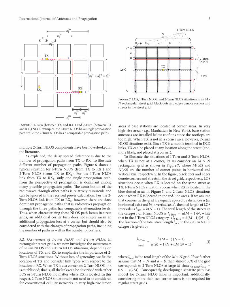

International Journal of
AerospaceEngineeringHindawi Publishing Corporationhttpwwwhindawicom Volume 2014
RoboticsJournal of
Hindawi Publishing Corporationhttpwwwhindawicom Volume 2014
Hindawi Publishing Corporationhttpwwwhindawicom Volume 2014
Active and Passive Electronic Components
Control Scienceand Engineering
Journal of
Hindawi Publishing Corporationhttpwwwhindawicom Volume 2014
International Journal of
RotatingMachinery
Hindawi Publishing Corporationhttpwwwhindawicom Volume 2014
Hindawi Publishing Corporation httpwwwhindawicom
Journal ofEngineeringVolume 2014
Submit your manuscripts athttpwwwhindawicom
VLSI Design
Hindawi Publishing Corporationhttpwwwhindawicom Volume 2014
Hindawi Publishing Corporationhttpwwwhindawicom Volume 2014
Shock and Vibration
Hindawi Publishing Corporationhttpwwwhindawicom Volume 2014
Civil EngineeringAdvances in
Acoustics and VibrationAdvances in
Hindawi Publishing Corporationhttpwwwhindawicom Volume 2014
Hindawi Publishing Corporationhttpwwwhindawicom Volume 2014
Electrical and Computer Engineering
Journal of
Advances inOptoElectronics
Hindawi Publishing Corporation httpwwwhindawicom
Volume 2014
The Scientific World JournalHindawi Publishing Corporation httpwwwhindawicom Volume 2014
SensorsJournal of
Hindawi Publishing Corporationhttpwwwhindawicom Volume 2014
Modelling amp Simulation in EngineeringHindawi Publishing Corporation httpwwwhindawicom Volume 2014
Hindawi Publishing Corporationhttpwwwhindawicom Volume 2014
Chemical EngineeringInternational Journal of Antennas and
Propagation
International Journal of
Hindawi Publishing Corporationhttpwwwhindawicom Volume 2014
Hindawi Publishing Corporationhttpwwwhindawicom Volume 2014
Navigation and Observation
International Journal of
Hindawi Publishing Corporationhttpwwwhindawicom Volume 2014
DistributedSensor Networks
International Journal of