research article modelling framework to support decision ... · pdf filemodelling framework to...
TRANSCRIPT
Hindawi Publishing CorporationAdvances in Decision SciencesVolume 2013, Article ID 234939, 23 pageshttp://dx.doi.org/10.1155/2013/234939
Research ArticleModelling Framework to Support Decision-Making inManufacturing Enterprises
Tariq Masood1,2 and Richard H. Weston1
1 Manufacturing and Materials Department, School of Applied Sciences, Cranfield University, Cranfield, Bedfordshire MK43 0AL, UK2 Rolls-Royce plc, P.O. Box 31, Derby DE24 8BJ, UK
Correspondence should be addressed to Tariq Masood; [email protected]
Received 29 January 2012; Revised 10 October 2012; Accepted 15 October 2012
Academic Editor: Albert Jones
Copyright © 2013 T. Masood and R. H. Weston.This is an open access article distributed under the Creative Commons AttributionLicense, which permits unrestricted use, distribution, and reproduction in anymedium, provided the originalwork is properly cited.
Systematicmodel-driven decision-making is crucial to design, engineer, and transformmanufacturing enterprises (MEs). Choosingand applying the best philosophies and techniques is challenging asmostMEsdeploy complex andunique configurations of process-resource systems and seek economies of scope and scale in respect of changing and distinctive product flows. This paper presentsa novel systematic enhanced integrated modelling framework to facilitate transformation of MEs, which is centred on CIMOSA.Application of the new framework in an automotive industrial case study is also presented. The following new contributions toknowledge aremade: (1) an innovative structured framework that can support various decisions in design, optimisation, and controlto reconfigure MEs; (2) an enriched and generic process modelling approach with capability to represent both static and dynamicaspects of MEs; and (3) an automotive industrial case application showing benefits in terms of reduced lead time and cost withimproved responsiveness of process-resource system with a special focus on PPC. It is anticipated that the new framework is notlimited to only automotive industry but has a wider scope of application.Therefore, it would be interesting to extend its testing withdifferent configurations and decision-making levels.
1. Need for ResponsiveManufacturing Enterprises
Makingwell-informed decisions that lead to timely responsesto change is vital to the long-term existence of many MEs[1–3]. Present day MEs cannot sustain if they concentrateonly on their current set of products and services and ontheir current operational procedures, processes, and systems.Over shortening life spans of products the profits that can begained from fixed production systems will vary significantlyover time. Hence the long-term success of a company liesnot only in the capabilities and attractiveness of its productsbut also in the product realising systems it uses to makeproducts and in the processes it uses to engineer change toits product realising systems [4]. According to a survey ofmanufacturers [5], it is evident that many companies needto continue to transform their systems (see Figure 1). Forinstance, in 2006, 57% of manufacturers thought that newproduct developmentwas a key priority in their business.Thiskind of enterprise transformation will often lead to needed
changes in production lines, raw materials, and/or supplychains, and this was reported to be another strategic areaof importance for 58% of manufacturers in 2006. There aremany other challenges to present day MEs like continuing tosucceed despite growing business competition, finding betterways of coping with increased complexity of products andprocesses, and an increasing need to make rapid responsesto changing requirements of customers. Although MEs aretypically supported by a variety of suitably engineered humanand machine resources, information systems and organi-sation structures, nonresponsiveness may mean an end toany given business. The next generation of manufacturingsystems therefore, need to be suitably reconfigured on anongoing basis by effective processes of change engineering,which generally will require complex processes involvingmany types of decision-making [1–3].
The present day customer typically imposes significantproblems to and constraints on MEs. For example, they mayrequest change in product qualities, quantities, cost, delivery,and service performance. Implications of a customer focus

2 Advances in Decision Sciences
Cost reduction
Improving quality
Staff skills training
Optimising materials flow around the factory
Supply chain management
New product development
Reducing time to market
Improving maintenance
Investment in new production equipment
Optimising existing IT systems
Investment in new IT systems
91%
71%
68%
63%
58%
57%
54%
42%
33%
25%
17%
5%Investment in new comms/telecomms systems
Figure 1: Key priorities in business strategy [5].
are time to market is shortening, products need to be tailoredto meet a breadth of customer needs, and demand is variable[6–8]. However, normally MEs cannot simply respond byrapidly deploying new processes and resources. Generallythey need to redeploy (i.e., reconfigure and reintegrate) theirexisting processes and resources such that they can respondcompetitively on an ongoing basis.
The manufacturing world is continually changing. It ismoving focus from economy of scale to an economy ofscope and is becoming a global economy for mass customi-sation [9]. For many companies around the world, stayingin business means to meet customer requirements and beinnovative, reduce the time-to-market of products, andman-ufacture quality products at competitive cost. In the wake ofthis rapidly changing business environment, new generationsof reconfigurable manufacturing systems have emerged andnewME organising structural patterns and systems are beingdeployed. To complement these advances, however, alsoneeded is better enabled ME decision-making; both withrespect to supporting individual decision-making roles andwith respect to realising better integrated decision-making.Industrially advanced countries have initiated research anddevelopment programs, namely, Manufacturing-2020 (UK),Next Generation Manufacturing (National Science Founda-tion, USA), and Intelligent Manufacturing Systems (Industryled R&D initiative from EU countries, Japan, Korea, Switzer-land, and USA).
2. Model-Driven ME Design
In general, current approaches to ME design do not enableprocesses, and their under pinning resource systems andsupport services, to be readily implemented and transformed[10]. Therefore, achieving effective levels of agility, flexibility,postponement, systems and departmental integration, andglobalisation have posed real challenges for present day MEs.
Hence commonly organisations face the challenge of trans-forming their operations to match dynamic not static busi-ness environments [11]. Significant transformation is ongoingin environments in which modern MEs must operate com-petitively. Pontrandolfo and Okogbaa [12] presented a reviewof global manufacturing and identified two problem levels:(1) a configuration level related to strategic decision-makingand (2) a coordination level related to operational issues [12].Quick and timely responses of various production systemtypes are vital for MEs to remain competitive [1–3]. One keycommon response is for MEs to have a broadened productportfolio. But to compete on such a basis they must deployan effective and change-capable set of human and technicalresource systems. Also because of falling product lifetimesand growing customisation requirements, the deployment ofthese resource systems will increasingly need to give rise toeconomies of scope and mass customisation [9]. For manycompanies around the world, staying in business necessitates(1)meeting specific customer requirements innovatively andeffectively, (2) reducing the time-to-market of products, and(3)manufacturing quality products at competitive cost.
Enterprise modelling and integration (EMI) techniqueshave been developed based on decomposition and configura-tion concepts, with modelling methods provided to analyseand engineer business processes (BPs). The application ofthese techniques has potential to reduce risks arising fromuncertainty; thereby increasing chances of realising success-ful BP operation and interoperation. These innovations alsohave potential to enable organisations to capitalise knowledgeand react to change effectively and efficiently. Systematicdecomposition and analysis of complex systems is possiblewith the aid of supporting EMI architectures, approaches,and tools. However, realising the potential of EMI tech-nologies gives rise to far from trivial problems. The skillwith which EMI technologies are used in conjunction withother modelling technologies, such as simulation modelling(SM) and information technology (IT) systems engineering

Advances in Decision Sciences 3
technologies, will determine the extent to which benefitsof improved ME systems design and interoperation can inpractice be realised. For example, themodels developed usingthese various technologies need themselves to be reconfig-urable and interoperable to synchronise their developmentand deployment of specific and targeted change-capableenvironments [13–15].
There is a wide scope of adopting modelling methodsto enhance reconfigurability during the design and redesignphases of manufacturing processes/systems. The models forsuch systems also need to be reconfigurable and interoperablein order to synchronise with the change-capable environ-ments. There have been recent advancements to extend thecoverage of public domain open systems architectures and tobridge the gap between enterprise and simulation modelling.Some important developments include a component-basedapproach for the design and construction of change-capablemanufacturing cell control [16–18] and its applications inthe automotive industry [19] and electronics SMEs [20]; amultiprocess modelling (MPM) approach [10]; the enrichedMPM approach [21]; and an enhanced use of enterprise andsimulation modelling techniques to support factory change-ability [22]. It is noted that use of the Computer-IntegratedManufacturing Open Systems Architecture (CIMOSA) hasbeen central to these developments. Current approaches tomodelling complex MEs adopt the use of multiperspectiveviews of present day problems. However, there is a needfor integration of different manufacturing system modellingviews and technologies in order to make the models andhence manufacturing systems reconfigurable and responsiveto upcoming change [1–3, 15, 23–25].
3. Need to Improve the Design andEngineering of Future MEs
The identification of methods by which manufacturingimprovements can be achieved is ongoing and has led toa range of approaches in recent years including lean, agile,changeable and reconfigurable manufacturing [2, 26–30].Progressive improvements in information system capabilitiescontinues to offer support for improved decision-making[31, 32]. It also follows that ME personnel must have (indi-vidual and collective) in-depth understandings about specificprocesses and resource systems and that these processesmust be flexible enough to change whenever the need arises.The complexity of manufacturing systems is reaching thatof many natural (e.g., economic and political) systems, thusongoing redesign and reengineering of future responsive andreconfigurable MEs (RMEs) requires the use of systematicapproaches, which deploy various types of system models tounderstand current and possible future behaviours and toinform systems engineering decision-making [25] .
Technological innovation has induced very significantchange in industry during recent times. This has impactedsignificantly on the way MEs operate and compete with eachother. But in general MEs are complex entities: designed,managed, and changed by people and the supporting systems
that people design; to realise customer and stakeholder (peo-ple) requirements; by deploying operational (technologicaland people) resources in innovative, systematic, and timelyways that generate competitive behaviours. Because typicallyMEs have multipurposes and stakeholders, it is difficult todecide howbest (and therefore near optimal) to design, select,and develop the technological systems (such as ERP andCAD/CAM systems) they deploy. Also for many reasons itis difficult to change them rapidly and in ways that enhancecompetitive ME behaviours. Whereas comparatively it willlikely be simpler, easier, and faster to design and realisechange to systems with a single well-defined purpose andsmall set of stakeholders. Evidently, therefore, there arisesa need to seek to deploy decomposition principles aimedat breaking down complex systems into readily understood,and reusable human and technical building blocks, whichcan be used as interoperating “components” (or modules) ofwider scope and complex MEs that can be reconfigured asrequirements change [25, 33]. Globalisation is one outcomefrom technological innovation within MEs, but this raisesfurther complication and a need to deploy decompositionprinciples.With sufficient resources, many entrepreneurs cannow physically or virtually relocate themselves and theirproducts (knowledge, experience, ideas and artefacts) tovarious locations around the globe. This has enabled knowl-edge sharing on a worldwide basis and technical systemsglobalisation.
The combination of global competition and customer-oriented manufacture implies that modern manufacturingsystems must be flexible, agile, reactive, integrated, andcost efficient [6]. It follows that designing or redesigningfuture RME requires the adoption of systematic approachesprovided that ME must have in-depth understanding of itsprocesses and that these processes must be reconfigurableenough to transform whenever the need arises.
4. Business Environment and Specific Need fora New Modelling Framework
Key research challenges identified in the literature reviewincluded the following: (1)how to copewith customer-relateduncertainties and complexities in a manufacturing business;and (2) lack of structured, explicit, and quantitative mod-elling methods to design and develop planning and controlsystems that can address research challenge 1 for differenttypes of manufacturing systems [2, 9, 10, 25, 34]. To addressthese research challenges, an innovative integratedmodellingframework (IMF) for designing and engineering responsiveand reconfigurable MEs is proposed and presented in thispaper. In a typical business environment, customers requesta manufacturer to produce a given quantity of a product(or products) in an agreed or required time frame. Oftenproducts requested by different customers vary from oneanother, and this variance forms a source of complexitywith which the production system must deal, commonlywhere customer orders are placed. The variance can alsotransform over time, for example, when new or customisedproducts come on stream. Another dimension of complexity

4 Advances in Decision Sciences
is volume or quantity in which a product is required to bemade. As the number of orders and/or numbers in eachorder increases it becomes more difficult for a productionsystem to cope with the demand. Therefore, the productdynamics (PD) includes product variance (delta 𝑃), volumevariance (delta 𝑉), and hence customer order (CO) variance(delta CO), which is composite of delta 𝑃 and delta 𝑉. Itfollows that to cope with customer-related transformationin any business environment; any production planning andcontrol (PPC) system is required to play an important role toattenuate unwanted dynamic impacts on available but limitedproduction resources. The PPC system can be viewed asgenerating a work dynamic (WD), which is an attenuatedform of PD and is used as input to processes (Pr) andresources (Re). The PPC system can use various controlalgorithms to seek to optimally deploy Pr and Re elements sothat product outputs can be achieved, responsively. Figure 2shows typical customer-related impacts in a conceptualisedcombined business, engineering andmanufacturing environ-ment.
The design of a production system is typically greatlyinfluenced by the nature of the product and work dynamicsas shown in Figure 2. Therefore, the PPC system aims toreduce impacts on production systems of the rate of changein product design and demand.The PPC systemmay be seenas a place where impacts arising from the rate of change inCOs, product types, and design are relatively fast (i.e., hasa significant dynamic). Most likely in comparison Re goesthrough medium changes while the Pr goes through slowchanges. Hence ideally, where possible there is a need todecouple Pr-Re couples from PPC system, so that it becomespossible to optimise workloads by flexibly distributing them.The need also arises to understand the dynamic impacts ofchanges in customer requirements, such as on (a) the designof production system decisions and (b) production engi-neering decision-making related to process plans, productionschedules, and the sequencing and control of work. Ideallyany future approach needs to consider such dynamics andtheir interrelationship. This mainly concerns understanding,representing, computer executing and virtually experiment-ing the relations between the WD, Pr, and Re while alsoconsidering the impacts of WD on Pr and Re [35]. Thechanges in WD come from the way in which the PPCSattenuates the PD.While the ability of any production systemto cope with a generated WD will depend on characteristicsof its Pr and Re subsystems and how these are configured andprogrammed into a production system.
Modelling approaches have a potentially significant roleto play in enabling decision-making and in supporting sys-tems composition.This can include PPC strategy selection tofacilitate responsivemanufacturing. BP analysis aided by EMIcan reduce risks and improve the chances of implementingsuccessful BPs. It also enables organisations to capitaliseknowledge so that they can react by changing operationsin an effective, efficient, and responsive manner. Systematicdecomposition and analysis of complex systems is possiblewith the aid of supporting architectures and by using comple-mentarymodelling techniques, which can include EM, CLM,SM, and Work Flow Modelling (WfM) [13]. The models of
ME processes, resource systems, and workflows so createdneed themselves to be reconfigurable and interoperable inorder to synchronise between virtual and real elementsof processes and systems that need to interoperate withindynamic (often uncertain) environments [14]. In principle,by achieving integration of different modelling approaches,new opportunities will arise to make the models live andresponsive to upcoming but “yet to be determined” rapidchanges [14].
5. The Proposed Integrated ModellingFramework (IMF)
In this section it is explained how PPC problems arisingin the context described in the foregoing section can besystematically addressed via the use of a stepwise IMF.The IMF is new process-based, modular approach, whichis proposed with a view to support explicit definition orconceptual design and virtual testing of alternative MEsystem compositions composed of reusable systemsmodules.The proposal is founded on the use of ME design andchange principles that include the following: (a) the modulescan be flexibly (re)configured or (re)composed into higher-level systems of modules or systems; (b) the modules arethemselves flexible configurations of human and technical(machine + IT) resources that possess abilities to realiseassigned processing activities which lead to defined goals;(c) the modules can be (re)programmable resources, that is,possess changeability enabling them to reach various statesconstrainedwithin their design envelope; (d) needed productrealising processes can be explicitly decomposed into feasibleroles that modules (of people and technical resources) canrealise; and (e) modules can be attributed to one or manyroles, therefore their actual assignments to roles need to bescheduled and controlled in order to achieve the desired typesand scenarios of responsiveness.
The primary modelling steps that constitute the IMF, andwere defined to support integrated decision-making aboutvarious aspects of ME systems, are illustrated by Figure 3.
Step 1. Use of a proven Enterprise Modelling (EM) method-ology and framework to create and validate visual processmaps that explicitly describe a “big picture” of the reality inthe subject organisation and its operating domains.
Step 2. Use of EM concepts and tables to populate processmaps with “resource” and “work” data. This data can beflexibly attributed to process elements forming the EM socurrent and possible future ME system configurations can beexplicitly described in terms of coupled process, resource, andwork types and work flow elements [34].
Step 3. Development of multilevel of abstraction “fit for pur-pose” Simulation Models (SMs) that are designed to modelthe behaviours of selected segments of ME systems. Herereuse is made of structural relationships connecting process,resource, and work flow elements of ME systems previouslydefined at various abstraction levels during modelling Steps1 and 2. By so doing the modeller can explicitly decompose

Advances in Decision Sciences 5
product
volume
customer
Controlalgorithms Responsiveness
Product type 1
Product type 2
Product type 3
Product dynamic(PD)
Productioncontrol
Workdynamic
(WD) Processes
Resources
Production system
The internal environment of a typical ME
Product type 1
Product type 2
Product type 3
Productoutputs
Customer
variance
required
orders
(Pr)
(Re)
Δ
Δ
Δ
Figure 2: A typical business environment.
the big picture of the ME into one or more specific seg-ments of ME systems, which need to be recoded using anappropriate choice of simulation technology to provide “fitfor purpose” support of particular needs of targeted MEdecision-makers, whilst ensuring that the integrity of thestructural design of the specific ME segments modelled viaSMs is maintained and conforms to the wider organisationalcontext defined by the EM of the subject ME. Any givenengineering project, focussed on realising a change to anME,will involve a distinctive set of decision-making roles, hencethe steps of the IMF are geared towards explicitly under-standing decision-making needs with respect to the scopeand focus of ME systems of concern to each decision-maker.Consequently, appropriately configured and focussed systemsegments can be computer executed using proven simulationtools to help decision-makers better understand behaviouralconstraints placed on the responsiveness of existing MEsystem configurations, by replicating known behaviours ofthe ME and by predicting potential future behaviours arisingfrom feasible changes made to the configuration of MEsystems. Here it is important to consider that it can takelong time to build and maintain simulation models, andreduced lead-time is critical in decision-making. Simulationmodelling can also prove costly in terms of time and money.
Step 4. Use of the coherent set of “fit for purpose” SMs topredict potential future behaviours arising from decision-making.
The proposed elements and elemental relationships of theIMF for designing future RME are explicitly documented
in this section by using modelling notations of the well-established Integration Definition for Function Modelling(IDEF0) standard [36]. The IDEF0 method is adopted herebecause (1) it can usefully model the design steps involvedin the IMF for future RME and (2) it is a well-establishedfunction modelling standard issued by National Institute ofStandards and Technology (NIST), USA. In this standardmethod, a square box is used to denote manufacturingfunctions along with arrows to show inputs (arrows fromleft), controls (arrows from top), and mechanisms (arrowsfrombottom) andoutputs (arrows stemming outwards right).An overview of the IDEF0 method is shown in Figure 4.
Changes in customer orders, products, and work-relateddynamics impact upon the need to redesign a responsivemanufacturing system. The proposed purpose for the IMFfor future RME is to systemise and facilitate the (re)designprocess by making use of the modelling concepts and tointegrate explicit descriptions of Pr-Re (Process-Resource)couples at needed levels of abstraction and thereby to visu-alise and document the way work types and flows related tothese Pr-Re couples, which can be viewed as being modularbuilding blocks of models of ME systems at a higher level ofabstraction.This is intended to result in identified systematicways of improving the responsiveness of a subject ME andits constituent business, engineering, and manufacturingsystems. Figure 5 shows the main IDEF0 diagram for theproposed IMF.
The following design steps are proposed to conform to theIMF: (a) create enterprise models and (b) create simulationmodels. While creating enterprise and simulation models, aspecific modelling formalism is followed, keeping in mind

6 Advances in Decision Sciences
Step 1:Enterprise
modelling (bigpicture)
Step 2:Enterprisemodelling
(process mapswith resource
and work data)
Stage 1: Enterprise modelling
Step 3:Simulation
modelling (As-Isconfigurations)
Step 4:Simulation
modelling (nextgeneration
configurations)
Stage 2: Simulation modelling
Figure 3: The IMF for RME (a simplified version).
Manufacturingfunction OutputsInputs
Controls
Mechanisms
Figure 4: The IDEF0 Method.
overall objectives of any given ME engineering project. Dif-ferent modelling blocks and identifiers are used to uniquelyrepresent models in terms of CIMOSA (and non-CIMOSA)domains, activities, events, information, physical and humanresources, flow of processes, resources or materials, alterna-tive flows, and finances. Key Performance Indicators (KPIs)are used to benchmark designedmanufacturing performancewith reference to overall objectives. Figure 6 shows the designsteps undertaken for the IMF.
5.1. Design Steps for Creating Enterprise Models (A1). Thefollowing steps are undertaken while creating enterprisemodels: (1) create context diagram(s); (2) create structurediagram(s); (3) create interaction diagram(s); and (4) createactivity diagram(s).While creating enterprisemodels, relatedEM formalisms are followed while keeping in mind overallobjectives of the exercise and CIMOSA and non-CIMOSAdomains. Different modelling blocks and identifiers are usedto uniquely document enterprise models. Figure 7 showsthe modelling sequence followed while creating enterprisemodels.
5.1.1. Design Steps for Creating Context Diagram (A11). Theoverall objective of creating a context diagram is to determinethe scope of involvement from a process-oriented point of
view. It is written in the manner “verb + noun,” meaning like“something is being done, or going to be done.” It representsa process as a central concern not a function.Things involvedin realising this objective are domains associated with thatobjective. CIMOSA domains are represented using oval-shaped modelling blocks, and non-CIMOSA domains withcrossed-out oval shaped modelling blocks. Domains arenamed as “nouns.” Identifiers are assigned to domains as(DM+ unique number). Figure 8 shows the steps undertakenfor creating context diagram(s) as follows: (1) identify anddocument relatedCIMOSADP(s); (2) identify anddocumentnon-CIMOSADP(s); and (3) identify and assign identifiers toDP(s).
5.1.2. Design Steps for Creating Structure Diagrams (A12).Generally, one top level structure diagram may be developedfor each domain under consideration. The DP is representedin the centre of the diagram while developing the structurediagram. The BPs involved in a DP are identified andassociated with the DP. Identifiers are given to BPs as (BP +domain identifier + uniqueBPnumber). Sub-BPs andEAs areidentified for each BP. The EAs are represented under eachBP. Identifiers are given to sub-BP as (BP + BP number +“-” + sub-BP number). Identifiers are given to EAs as (EA +BP or sub-BP or DP number + unique EA number). Figure 9shows the steps normally undertaken for creating structurediagram(s) as follows: (1) specify and document structurediagram(s); (2) identify BP(s) involved in this DP and assignidentifiers; (3) identify and assign identifiers to sub-BP(s);and (4) identify and assign identifiers to EAs.
5.1.3. Design Steps for Creating Interaction Diagrams (A13).One top level interaction diagram can be created for eachobjective under consideration. The top level interaction dia-gram is created by considering interactions between domainsinvolved in the context diagram(s). Those interactions areconsidered to occur between DP(s) owned by the interactingdomains. Identifiers are assigned to DP(s) as (DP + domainnumber). Between any two DPs, only information, humanresource(s), physical resource(s), event(s), and finance arerepresented in interaction diagram(s). One interaction dia-gram is created for each domain under study. In subsequentinteraction diagrams, DPs are decomposed and represented

Advances in Decision Sciences 7
Customer orderdynamics
Product dynamics
Work dynamics
Modellingconcepts IMF
Identified ways ofimproving
responsiveness
A0
control
design of aresponsive
manufacturingenterprise
(Re)
Pr-Re
∗IMF = integrated modelling framework, Pr = process, Re = resource
Figure 5: The IMF for RME: (Re)Design of a responsive manufacturing enterprise (Main).
Modellingblocks
Identifiers
Enterprisemodels
Modellingblocks
Identifiers
KPIs
Simulationmodels
Simulationmodelling
tools
Enterprisemodellingformalism
Businessrequirements
Processnetwork Create enterprise
models
A1Create simulation
models
A2
Identifiers: these are used to identify modelling blocks with theirunique alpha-numeric values, for example DM2 to identify domain 2.
Figure 6: Design steps for the IMF (A0).
as sub-DPs or BPs. A DP not under consideration is rep-resented as an external link. While creating subinteractiondiagrams, domains under consideration are represented interms of either their sub-DPs or BPs. Decisions are takenon the basis of ease in the modelling effort, understandingto be developed and subsequent need for development ofstructure diagrams. Identifiers are assigned to sub-DPs as(DP + parent DP number + unique number of this sub-DP),and to BPs as (BP + parent DP number + unique number
of this BP). Figure 10 shows steps undertaken for creatinginteraction diagram(s) as follows: (1) specify and documentinteraction diagram(s); (2) identify BP(s) involved in this DPand assign identifiers; (3) identify and assign identifiers tosub-DP(s); and (4) identify and assign identifiers to BP(s).
5.1.4. Design Steps for Creating Activity Diagrams (A14). Theactivity diagrams are normally developed from structure

8 Advances in Decision Sciences
Modellingblocks andidentifiers
Contextdiagram
Modellingblocks andidentifiers
Structurediagram(s)
Modellingblocks andidentifiers
Interactiondiagram(s)
Modellingblocks andidentifiers
Activitydiagram(s)
Activitydiagram
formalism
Interactiondiagram
formalism
Structurediagram
formalism
Contextdiagram
formalism
Businessrequirements
Process network Createcontext
diagram(s)
Createinteractiondiagram(s)
Createactivity
diagram(s)
Createstructure
diagram(s)
A11
A12
A13
A14
Identifiers: these are used to identify modelling blocks with their unique alpha-numericvalues, for example DM2 to identify domain 2.
Figure 7: Design steps for creating enterprise models (A1).
Oval-shapedmodellingblocks andidentifiers
DocumentedCIMOSAdomain
process(es)
Crossed-outoval-shaped
modelling blocksand identifiers
Documented non-CIMOSA domain
process(es)
Contextdiagram
Contextdiagram
formalism
Contextdiagram
formalism
Contextdiagram
formalism
Businessrequirements
Processnetwork
Identifiers: these are used to identify modelling blocks with their unique alpha-numeric values,for example DM2 to identify domain 2.
A111
Identify anddocument
non-CIMOSAdomain
process(es)
Identify anddocumentrelevant
CIMOSAdomain
process(es)
A112
Identify andassign
identifiers todomain
process(es)
A113
Identifier as“DM + unique
number”
Figure 8: Design steps for creating context diagram(s) (A11).
diagrams, so that their development remains positioned inthe context of their parent enterprise. The EAs, BPs, andsub-BPs, as identified in structure diagram, are sequencedtogether using the notations developed for activity diagrams.A complete end-to-end process is represented using activitydiagram formalisms with dependencies among EAs/BPs.Theflow of process, control, and resources is represented in
activity diagrams. If an end-to-end process cannot be accom-modated using one template, then further templates may beadded with dependencies shown between any two templates.It is important to place EAs/BPs on activity diagrams withrespect to a time line at the bottom of the activity dia-gram. Figure 11 shows steps undertaken for creating activitydiagram(s) as follows: (1) specify and document activity

Advances in Decision Sciences 9
Keep DP in thecentre of the
structurediagram
Relevantmodelling
blocks
Identifiers
Identifiers
Identifiers
Structurediagram(s)
Structurediagram
formalism
Structurediagram
formalism
Structurediagram
formalism
Structurediagram
formalism
Businessrequirements
Process network Specify anddocumentstructure
diagram(s) Identify businessprocess(es)
involved in thisDP and assign
identifiers
Identify andassign identifiers
to subbusinessprocess(es)
Identify andassign identifiers
to enterpriseactivities
A121
A122
A123
A124Identifiers: these are used to identify modelling blocks with their uniquealpha-numeric values, for example DM2 to identify domain 2.At A122: identifier as “BP + domain identifier + unique BP no.”At A123: identifier as “Sub-BP + BP no. + a dash sign (-) + sub-BP no.”At A124: identifier(s) as “EA+ BP no./sub-BP no./DP no. + unique number for each EA”
Figure 9: Procedural steps for creating structure diagram(s) (A12).
Relevantmodelling
blocksIdentifiers
Identifiers
Identifiers
Interactiondiagram(s)
Interactiondiagram
formalism
Interactiondiagram
formalism
Interactiondiagram
formalism
Interactiondiagram
formalism
Businessrequirements
Processnetwork
Specify anddocumentinteractiondiagram(s)
A131
Identify businessprocess(es)
involved in thisDP and assign
identifiers
A132Identify and
assign identifiersto subdomain
process(es)
A133 Identify andassign identifiers
to businessprocess(es)
A134Identifiers: these are used to identify modelling blocks with their uniquealpha-numeric values, for example DM2 to identify domain 2.At A132: identifier as “BP+ domain identifier + unique BP no.”At A133: identifier as “DP+ parent DP no.+ unique number of this Sub-DP”At A134: identifier as “BP+ parent DP no.+ unique number of this BP”
Figure 10: Design steps for creating interaction diagram(s) (A13).
diagram(s); (2) represent complete end-to-end process withdependencies among EAs/BPs; (3) represent the flow ofprocess, control and resources; and (4) carefully check thatthe EAs/BPs are appropriately placed with respect to the timeline.
5.1.5. Analysis of EM Tool Set. The EM templates facilitatethe process of IMF application in an enterprise. TheseEM templates basically provide a base for EM, followingwhich fit for purpose SMs can be conceptually designed andimplemented and simulation experiments can be conducted

10 Advances in Decision Sciences
Relevantmodelling
blocksActivity
precedence
Time line
Modelling blocksfor process,control andresources
Time line
Activitydiagram(s)
Activitydiagram
formalism
Activitydiagram
formalism
Activitydiagram
formalism
Activitydiagram
formalism
Businessrequirements
Process network Specify anddocument
activity digram(s)
A141
Representcomplete
end-to-end process with dependencies
among EAs/BPs
A142Represent the
flow of processcontrol andresources
A143
Carefully checkthat the EAs/BPs
are placed wrttime line at the bottom
A144
Identifier as“BP + domain
identifier + uniqueBP no.”
Figure 11: Design steps for creating activity diagram(s) (A14).
based upon the reuse of knowledge and data previously codedusing enterprise models. The EM templates make use of thefollowing formalisms:
(i) general blocks—which includes CIMOSA domain& non-CIMOSA domain activity, external link, andevent modelling constructs;
(ii) resources—which include information (resource),HR (human resources), physical (resources), andfinance (related resources);
(iii) flow control logic—which includes conditional(logic), OR (logic), AND (logic), sub-process,chained process, and delay;
(iv) flow types—which includes flow of resource, flow ofprocess, and alternative flow;
(v) operation types—which includes direct generation,direct supportive, and indirect supportive (operationtypes).
Figures 12, 13, 14, and 15 show example use of contextdiagrams, interaction diagrams, structure diagrams, andactivity diagrams, respectively.
5.2. Design Steps for Creating Simulation Models (A2-1 andA2-2). The design steps for creating simulation models arelisted in the following: (1) gather simulation requirements;(2) select SM tool; (3) create AS-IS simulation model(s); (4)verify and validate the AS-IS simulation model; (5) createTO-BE simulation models; (6) verify and validate the TO-BE simulation models; (7) analyse results; and (8) implementTO-BE simulation models (where applicable). Figures 16 and
17 show steps undertaken for creating simulationmodels (A2-1 and A2-2).
5.3. Analysis and Selection of SM Tool Set. It is assumed thata set of computer and manual technologies and systems willbe used to understand the problem scenarios, execute theIMF, and provide suitable interfaces to users and modellersfor decision-making.During this research,MSVisiowas usedto create static enterprise and causal loopmodels. Proprietarysoftware packages were used to create simulation models,namely, Simul8, Plant Simulation, Arena, and iThink. Theselection of these specific software tool set was based upon(1)model requirements; (2)model KPIs; (3)modeller’s capa-bility to successfully model the required configurations; (4)acceptance of results by the peers; and (5) availability. Table 1shows authors’ capability set for the selected simulation tools.Furthermore, other modelling methods and case studies bythe authors and their research colleagues have successfullyutilised these software tool sets. Such interfaces enabled theauthors to (1) capture requirements data; (2) input data intomodels; (3) reconfigure a simulation model to meet variousspecified needs; (4) conduct various experiments based upondifferent configurations; (5) collect results; and (6) conductanalysis of results.
There has been a weak impact of enterprise architectureresearch in industry and insufficient maturity of standards onenterprise architectures including CIMOSA and GERAM inthe past two decades [37]. Hence it is important to know howto apply the IMF in general. Even though significant work hasbeen done on enterprise application integration during pasttwo decades, there are still several issues that have not been

Advances in Decision Sciences 11
DM2 CIMOSA domain
DM1 CIMOSA domain DM3
CIMOSA domain
DM4non-CIMOSA domain
DM5non-CIMOSA domain
DM6non-CIMOSA domain
DM7non-CIMOSA domain
General blocks
xyz1overall project domain
ActivityExternal linkEvent
Resources
InformationHRPhysicalFinance
Flow control logic
ConditionalOrAndSub-processChained processDelay
Flow typeFlow of resourceFlow of processAlternative flow
Operation typeDirect generationDirect supportiveIndirect supportive
CIMOSA domainNon-CIMOSA domain
ctx/xyz1-overall project domain
Figure 12: Example use of EM template for “context diagram.”
Table 1: Authors’ capability set for selected simulation software tools.
Simulation software tool set
iThink Simul8 Plantsimulation Arena Matlab/simulink Petrinets
Selection parameters
(1) Model requirements Contextdependant
Contextdependant
Contextdependant
Contextdependant
Contextdependant
Contextdependant
(2) Model KPIs Contextdependant
Contextdependant
Contextdependant
Contextdependant
Contextdependant
Contextdependant
(3) Modeller’s capability Good Good Good Good Good Good(4) Peer acceptance Good Good Good Good Average Good(5) Availability Good Good Good Good Good Good
addressed and they need to be studied further. Predicting theevolution of a particular piece of modelling software is oneof such issues [38]. This issue is crucial to achieving a nearoptimal trade-off for a particular enterprise between short-term gain and long-term suitability. A company could investin an enterprise application software system today in orderto obtain better support to its existing business functions,but that software may become obsolete in say 2-3 years.Any new software choice may bring some constraints onintroducing other new software systems due to their inabilityto communicate with previously existing software. This issuecould also be viewed in another way, namely, how could
one make decisions under uncertain situations (includinguncertainty in the evolution of any selected software tool)?The proposed IMF intends to be generic in a sense thatit could (re)use existing organisational resource systems(hardware, software, human) and organisational structure inorder to achieve the benefits of “openness,” “standardisedview,” “low-cost of change,” and “easier adaptation by theorganisation and its stake holders,” to name a few.
5.4. Discussion. The proposed IMF for future RME is illus-trated and documented through IDEF0 diagrams in this

12 Advances in Decision Sciences
General blocks
ActivityExternal linkEvent
Resources
InformationHRPhysicalFinance
Flow control logic
ConditionalOrAndSub-processChained processDelay
Flow typeFlow of resourceFlow of processAlternative flow
Operation typeDirect generationDirect supportiveIndirect supportive
CIMOSA domainNon-CIMOSA domain
DP1.1 DP2.1
DP4
.1
DP5
.1
DP3.1
Information
Information
Information
Information
Information
Information
Information
Information
Event
Event
Physical resource
DP7.1
DP6.1
Finance
Finance
ctx/xyz1 interaction diagram
Figure 13: Example use of EM template for “interaction diagram.”
ctx/xyz1-structure diagram
General blocks
ActivityExternal linkEvent
Resources
InformationHRPhysicalFinance
Flow control logicConditionalOrAndSub-processChained processDelay
Flow typeFlow of resourceFlow of processAlternative flow
Operation typeDirect generationDirect supportiveIndirect supportive
CIMOSA domainNon-CIMOSA domain
BP1.1.1
EA1.1.1.1
EA1.1.1.2
EA.1.1.1.3
DP1.1
BP1.1.4
EA1.1.4.1
BP1.1.2
EA1.1.2.1
EA1.1.2.2
EA1.1.2.3
Figure 14: Example use of EM template for “structure diagram.”

Advances in Decision Sciences 13
General blocks
ActivityExternal linkEvent
Resources
InformationHRPhysicalFinance
Flow control logic
ConditionalOrAndSub-processChained processDelay
Flow typeFlow of resourceFlow of processAlternative flow
Operation type
Direct generationDirect supportiveIndirect supportive
CIMOSA domainNon-CIMOSA domain
Event
Event
Event
EA1.1.5.1
EA1.1.6.1
EA1.1.7.1
EA1.1.8.1
EA1.1.9.1
EA1.1.10.1
Information
Information
Time scale
ctx/xyz1-activity diagram
Figure 15: Example use of EM template for “activity diagram.”
Enterprisemodels
Stakeholders
Conceptualmodel
Collecteddata
Design ofexperiments
Fitness to therequirement
Ease of use
Availability
Simul8Plant
simulation
Arena
Simulationmodelling tool
selected Enterprisemodels KPIs
Stakeholders
Gathersimulation
requirementsA21
Select simulationmodelling tool
A22Create AS-ISsimulationmodel(s)
A23 Verify andvalidate AS-IS
simulationmodel(s)
A24
Figure 16: Design steps for creating simulation models (A2-1).

14 Advances in Decision Sciences
AS-ISsimulation
model
Systemdynamics
KPIs
TO-BEscenarios
TO-BE SMs
Researcher
KPIs Stakeholders
Simulationmodelling
tool
Verificationand
validationmethod
Verified andvalidated SMs
Stakeholders
Create TO-BEsimulation
models (SMs)A25 Verify and
validate theTO-BE
simulationmodels (SMs)
A26 Analyseresults
A27
Implementation
A28
Re(design)of responsivemanufacturing
system
Figure 17: Design steps for creating simulation models—continued (A2-2).
paper and is composed of an integrated use of EM and SM,which is described in this paper in detail. The developmentof the IMF also led onto the development of a Manufacturingsystem integration UNified Environment (MUNE). In anumber of industry-based case studies (e.g., in automotive,bearing manufacturing, furniture manufacturing), such anenvironment has since played a pivotal role that enablesresponsiveness and reconfigurability in future RME [34, 39–41]. The MUNE proposed in this study has three primarydimensions alongwhich complex systemdecompositions canbe instrumented via suitable software system choice(s).Thesedimensions correspond to (1)modelling levels, (2)modellingviews, and (3) productionmanagement levels.Themodellingviews consist of the following: (a) product dynamics (PD),(b) customer order decoupling point (CODP), (c) workdynamics (WD), (d) performance metrics (PM), (e) EM, and(f) SM.Themodelling views include generic, partial, and par-ticular views that are similar to previously proposedCIMOSAmodelling views. The MUNE is presented conceptually inFigure 18.
In theory, the IMF offers the following solutions to MEengineering research challenges (as identified in Section 4).
(1) It provides a decomposition of the complexity typicalwithin MEs: in terms of delta orders, delta volumerequired, delta product variance, and so forth. Henceit promises to provide a way to cope with customer-related uncertainties and complexities and to matchME system configurations and their behaviours tolong- and short-term responsiveness needs.
(2) It provides a structured modelling framework and asshown in the research thesis of the first author [34],it provides a structured, explicit, and quantitativemodelling approach that has been used to facilitatethe design and development of production planningand control systems.
Table 2 shows weaknesses of formal methods found inspecific literature review and how these are addressed in theIMF.
6. Effectiveness of Applying the IMF inan Automotive Industry Case
The IMF was applied in an automotive industrial case study(where the ME concerned will be referred to as FPD inthe following). Reduction in lead time, cost, and work loadon a preproduction management team were key issues forthe management of the FPD. While applying the IMF inthis case study, comparisons of AS-IS and future (TO-BE)situations of pre-production control were presented. Basedupon observations made during this case study, the IMFproved to be useful but some limitations were also identi-fied [34]. Such limitations demanded for an enhancementof the IMF. The original IMF was based upon previouslydiscussed general literature review, detailed literature review,and early exploratorymodelling and results. Lack of adequatestructured data capturing methods and gaps in informationand data when transforming between EMs and SMs wereamong some limitations of the IMF. Hence a need wasraised to enhance the IMF in order to improve its appli-cation and achieve better results. This paper will presentan enhanced integrated modelling framework (EIMF) aftertaking into consideration lessons learnt during the FPD casestudy.
During the FPD case the authors made the followingobservations. CIMOSA provides a coherent set of modellingconstructs to explicitly represent processes, resource systems,information flows, and organisational structures of MEs.Along the “derivation” dimension, it provides multiperspec-tive modelling constructs that enable decomposition of theenterprise so as to handle high levels of complexity such that

Advances in Decision Sciences 15
Modellinglevels
Productionmanagement
levels
CODP
PD WDPM
EM SM
Modellingviews
PD: Product dynamicsCODP: Customer order
PM: Performance metrics
EM: Enterprise modelling (static)SM: Simulation modelling
Generic
Partial
Particular
decoupling pointWD: Work dynamic (Pr-Re couple)
Figure 18: MSI UNified Environment (MUNE).
Table 2: Weaknesses of formal methods in the literature and how these are addressed in IMF.
Weaknesses of formal methods in the literature How weaknesses are addressed in IMF
Lack of structured ways of explicitly defining therelatively enduring structures of business, engineering,and production systems used by a given specificmanufacturing enterprise.
EM:(i) This stage provides a structured base to understandthe business in context by usefully modelling theenterprise.(ii) It provides a way of systematic reuse of enterprisemodel fragments in the form of modelling diagramtemplates.(iii) The context, structure, interaction, and activitydiagrams help in producing and reconfiguringenterprise models in a rapid and effective way.
Lack of structured ways of creating “fit for purpose”simulation models that can support decision makingabout ME systems and how changes in the ME systemdesign can result in needed reachable enterprisebehaviours.
SM:(i) This stage provides benefits in terms of a structureddynamic analysis tool for decision making in terms ofachieving reconfigurability and responsiveness.(ii) It provides a basis for a structured decision makingfor TO-BE models by creating reconfigured simulationmodels and making comparisons with As-Is or otherTO-BE models.(iii) It provides a way to analyse and predict aboutalternative TO-BE options available to the ME.

16 Advances in Decision Sciences
understandings gained about process segments can be under-stood in detail within the organisational context specifiedby the parent enterprise model. In this way understandingsabout relatively enduring structural aspects of processes canbe gained at various levels of abstraction. Thereby both“big picture understandings” can be developed that crossorganisational boundaries and in depth process analysis canbe enabled by “drilling into” the model at needed levelsof modelling abstraction. The “generation” dimension isconcerned with the life cycle of the ME and its processes,resources, information flows, and its organisational struc-tures. Here definitive separation is made between “modelsof requirements” (generally expressed as process models thatcan be treated as a backbone model and attributed with othermodelled entities) and “models of conceptual solutions,”“detailed models of specific solutions,” and “implementationdescriptions” used to document implemented systems capa-ble of meeting defined requirements. In general such solu-tions will be configurations of active resource components(including people, automatedmachines, and IT systems).Thethird CIMOSA cube dimension “instantiation” is concernedwith the extent to which “models” and “implemented solu-tions” are general or specific and is of prime concern laterin this research. The basic idea is that enterprise models maydescribeMEs or parts of them from a structural point of view,equally they may describe some industry sector or commonstructural aspects of many MEs, or may simply describe oneparticular ME, or even just one particular part of one par-ticular ME. Here in principle enterprise modellers and otherenterprise engineers and decision-makers can particularisea generic model through a partially generic modelling stageto an ME specific one. Alternatively generalisation of specificor semigeneric models can lead to models and solutions thatcan be generally applied. In this scheme of things therefore anERP package is a semigeneric solution technology, which canbe made specific by inputting specific product, and so forth,data related to a specific ME.
However, in general enterprise modelling (includingCIMOSA) is designed to represent and communicate pri-marily structural (i.e., relatively enduring) aspects of anyME. CIMOSA modelling constructs are not designed to becomputer executed to simulate ME state change; if theywere then EMs used to model a complex ME, they wouldthemselves become too complex to deploy for all possibleenterprise engineering decision-making purposes. Hencewhere simulation experiments are needed to predict futurebehaviours ofME processes configured in different ways, andwhen using alternative resource systems, it is necessary tocomplement the use of EM with SM technologies; as SMtechnologies are designed to model and predict changes insystem behaviours.This section reviews the basis of the IMF’ssystematic approach to creating coherent sets of integrated(EM and SM) models that can interoperate to replicate andpredict changing organisational behaviours and to place thegenerated behaviours within the specific case organisationalcontext of a parent ME as modelled by a parent EM.
As described earlier at a generic level, the IMF providesa framework that encompasses the followingmain modellingstages.
Stage 1. Development of enterprise models, to represent theorganising structure of a specificME and its product realisingprocesses.
Stage 2. Development of multiple simulation models ofrelevant process segments where, with reference to needsof particular enterprise engineering decision-makers, it isnecessary to consider and encode: (a) the nature of thework that flows through production systems, where thesesystems comprise both “process elements” and “resourcesystem elements” and (b) best ways of configuring theproduction system elements, such that required “values” canbe added to those work flows. Simulation models are runusing alternative responsiveness strategies by inputting datainto AS-IS and possible TO-BE configurations of productionsystems (for various organisational departments). Before (orduring) running the simulations, certain KPIs are chosen toenable comparison and choice to be made between differentcombinations of responsiveness strategy and productionsystems configuration (composition). As soon as a nearoptimal solution (and therefore a suitable configuration ofME systems) is defined, the modelling and decision-makingprocess is stopped; otherwise it is carried on to find additionalcombinations of future responsiveness strategies and produc-tion system configurations (compositions).TheKPIs used forthis specific case study included lead time, cost, and resourceload. Table 3 shows results of AS-IS and selected TO-BEmodel configurations considered during experimentation. Itshows a significant reduction in lead time of TO-BE modelconfiguration of FPD, that is, from 66 days to 56 days.
While reviewing the IMF with respect to its use in theFPD case certain limitations were identified, as presented inthe following section.
6.1. Limitations of the IMF and Need for Enhancement. Theapplication of the IMF in the FPD case proved useful invisualising alternative pre-production control managementmethods. But during the application process, limitations ofthe IMF were also identified, namely,
(i) lack of adequate structured data collection for enter-prise models,
(ii) lack of linking EMs with SMs effectively,(iii) lack of verification, validations, and accreditation of
developed models,(iv) lack of structured output of the modelling exercises.
The authors, therefore, found that it was necessary: (1) todefine and deploy structured data collection methods duringEM stages; (2) to deploy “systems thinking” (via causal loopmodelling) to help better understand impacts of parameterchange and causality amongst parameters in complex man-ufacturing systems and thereby to design better SMs andSM experiments; (3) to exercise verification, validation, andaccreditation of enterprise and simulation models after allmodelling stages; and (4) to tailor the generic IMF towardsPPCpolicy selection. It is important to explore how to address

Advances in Decision Sciences 17
Table 3: AS-IS and TO-BE model configurations.
Modelconfigurations Strategy Time
(days)Resource load(engineers)
Cost of engineers($)
AS-IS Random assignment of work withdedicated resource groups 66 16.75
(Total: 33.04)58960
(Total: 118094)
TO-BE First come first serve with introduction ofthree flexible resource sets 56 13.30
(Total: 27.61)53201
(Total: 111781)
Difference 10 3.45(Total: 5.43)
5759(Total: 6313)
Percent improvement (%) 15.15% 20.60% 9.77%(Total: 5.35%)
key aspects of these identified IMF limitations.The followingsection will discuss the way in which the authors adoptedsystems thinking as an integral part of an enhanced form ofthe IMF.
6.2. Systems Thinking via Causal Loop Modelling. Causalloop models can visually represent causal effects betweenactivities [42, 43]. This type of modelling helps identifyaspects of complex system dynamics. When used as a stan-dalone technique, however, Causal Loop Modelling (CLM)is limited in support of complex manufacturing systemsdesign [44]. When applied on its own, CLM may proveuseful for strategic decision-making but generally it does notadequately encode complex systems except at a high level ofabstraction. However, when combined with suitable processmodelling technique(s) focussed on structural design, it mayprove useful for complex systems design, due to its abilityto capture the causality of dynamics and provide a basisfor qualitative analysis of businesses. Causal loop modelsby themselves cannot readily be quantitively modelled butthey can be transformed into equivalent iThink models forsimulation purposes. Previous to work of the authors andtheir colleagues, the literature had not shown that causalloop models being used in support of CIM implementation[44]. Masood [34, 45], Rashid et al. [46] and Agyapong-Kodua et al. [44] have further detailed and applied CLMs.The following will discuss model verification, validation, andaccreditation.
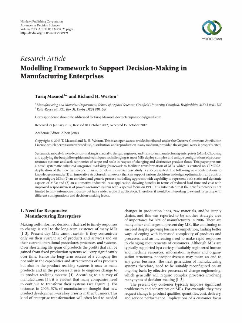
6.3. Verification, Validation, and Accreditation of Models.Verification, validation, and accreditation (VVA) of modelsis very important in establishing confidence and trust in amodel and its results. VVA terms are defined as follows.Verification is the process of determining that amodel imple-mentation accurately represents the developer’s conceptualdescription and specifications that the model was designedfor [47]. Validation is the process of determining the mannerand degree to which a model is an accurate representation ofthe real world from the perspective of the intended uses of themodel and of establishing the level of confidence that shouldbe placed on this assessment [47]. Validation is the processof establishing confidence in the usefulness of a model [48].Being “valid” means “well suited to a purpose and soundlyconstructed” but does not imply that a model somehowbecomes absolutely correct and true [49]. It is important to
validate the static models up to an acceptable level of accu-racy. The performance of the model needs to be comparedwith the operation of the real system to build confidence inthe results. It is important to note that the model may onlybe “valid for the purpose.” In reality, however, it may not bepossible to validate fully a model of a real system [20, 50–52]. Accreditation is the formal certification that a modelor simulation is acceptable for use for a specific purpose.The validation method adopted here generally follows themethod suggested by Robinson [50] (i.e., validation of staticmodel, data, codes, and black box approaches). Accreditationis conferred by theMEbest positioned tomake the judgementthat themodel or simulation in question is acceptable [47]. InMEs there may be many types of potential operational user,programme manager users, and contractor users, dependingupon the purposes intended. Figure 19 illustrates the basicdifferences between the VVA terms. Having explored thesystems thinking and model verification, validation, andaccreditation, the next section will propose the EIMF.
7. The Enhanced Integrated ModellingFramework (EIMF)
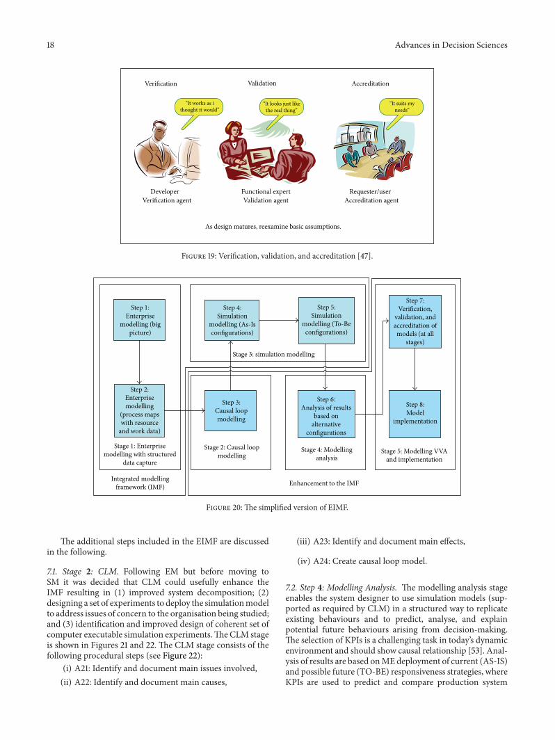
In this section an enhanced form of the IMF is proposed,which is based on observations made during the FPD casestudy.The EIMF is designed to engineer change/reconfigura-tionwithinMEs, and relative to the IMF it includes additionalsteps of (1) using structured data capturing methods duringmodelling Stage 1, (2) creating causal loop models if andwhere necessary, (3) using structured modelling analysisbased upon results of alternative configurations (e.g., pro-duction policy matrix within the IMF stages), (4) VVA ofmodels after modelling stages, and (5) model implemen-tation, which aims to enhance the framework resulting inmore logical models of any complex system under study. Thestepwise EIMF modelling approach is shown conceptually inFigure 20, while its relationship with respect to the IMF canbe expressed as follows:
EIMF = IMF
+ Stages of (CLM +Modelling Analysis
+VVA + Implementation) .
(1)
18 Advances in Decision Sciences
Verification Validation Accreditation
“It works as ithought it would”
“It looks just likethe real thing”
“It suits myneeds”
DeveloperVerification agent
Functional expertValidation agent
Requester/userAccreditation agent
As design matures, reexamine basic assumptions.
Figure 19: Verification, validation, and accreditation [47].
Step 1:Enterprise
modelling (bigpicture)
Step 2:Enterprisemodelling
(process mapswith resource
and work data)
Stage 1: Enterprisemodelling with structured
data capture
Integrated modellingframework (IMF)
Step 4:Simulation
modelling (As-Isconfigurations)
Stage 3: simulation modelling
Step 5:Simulation
modelling (To-Beconfigurations)
Step 3:Causal loopmodelling
Stage 2: Causal loopmodelling
Step 6:Analysis of results
based onalternative
configurations
Stage 4: Modellinganalysis
Step 7:Verification,
validation, andaccreditation ofmodels (at all
stages)
Step 8:Model
implementation
Stage 5: Modelling VVAand implementation
Enhancement to the IMF
Figure 20: The simplified version of EIMF.
The additional steps included in the EIMF are discussedin the following.
7.1. Stage 2: CLM. Following EM but before moving toSM it was decided that CLM could usefully enhance theIMF resulting in (1) improved system decomposition; (2)designing a set of experiments to deploy the simulationmodelto address issues of concern to the organisation being studied;and (3) identification and improved design of coherent set ofcomputer executable simulation experiments.TheCLM stageis shown in Figures 21 and 22. The CLM stage consists of thefollowing procedural steps (see Figure 22):
(i) A21: Identify and document main issues involved,(ii) A22: Identify and document main causes,
(iii) A23: Identify and document main effects,
(iv) A24: Create causal loop model.
7.2. Step 4: Modelling Analysis. The modelling analysis stageenables the system designer to use simulation models (sup-ported as required by CLM) in a structured way to replicateexisting behaviours and to predict, analyse, and explainpotential future behaviours arising from decision-making.The selection of KPIs is a challenging task in today’s dynamicenvironment and should show causal relationship [53]. Anal-ysis of results are based onMEdeployment of current (AS-IS)and possible future (TO-BE) responsiveness strategies, whereKPIs are used to predict and compare production system

Advances in Decision Sciences 19
ProcessnetworkBusiness
requirements
Enterprisemodellingformalism
Causal loopmodellingformalism
Simulationmodelling
tools
Simulationmodels
KPIs
IdentifiersModelling
blocks
Causal loopmodels
IdentifiersModellingblocks
Enterprisemodels
IdentifiersModellingblocks
Createenterprise
models
A1 Create casualloop models
A1
A2
Createsimulation
models
Identifiers: these are used to identify modelling blocks withtheir unique alpha-numeric values, for example DM2 to identify domain 2.
Figure 21: Design steps of EIMF to reconfiguring MEs.
Staticmodels
Stakeholders KPIs
Main issuesidentified
Researcher
Stakeholders
Researcher
KPIs
Main causesidentified
Stakeholders
KPIs
Researcher
Main effectsidentified
Modellingblocks
IdentifiersKPIs
Causal loopmodels
Causal loopmodellingformalism
Causal loopmodelling
tool (if used)
Identify anddocument
main issuesinvolved
A21 Identify anddocument
main causesA22
Identify anddocument
main effectsA23
Create causalloop models
A24
Figure 22: Procedural steps of CLM (A2).
behaviours under alternative strategies. The decision-makersmight be considering KPIs, for example, time (reduced leadtime or ramp up time), cost (reduced production cost or lifecycle cost), and so forth, but not limited to these only.
7.3. Step 5: Modelling VVA and Implementation. The AS-IS enterprise and simulation models generally need VVAbefore embarking on TO-BE model generation and testing.Also, upon reaching a near optimal model reconfigurationsolution, the results require VVA. In effect, this process iscarried out at all stages and formally acknowledged beforeimplementation. Hence before final selection of strategy and
production system configurations presentations are madeto relevant funders and managers. Upon successful VVA,the ME management may approve the finalised TO-BEreconfiguration solution to be implemented within the ME.Table 4 presents an overview of the methods and tools to beused in EIMF. It is anticipated that the EIMF will be tested inmore complex situations by going into further depth of MEproduction control.
7.4. Significance of the EIMF. The EIMF is an enhancedversion of the IMF and significance of its use is presentedin the following (and is in addition to the aforementionedsignificance of the IMF):

20 Advances in Decision Sciences
Table 4: Overview of the EIMF—the methods and tools to be used.
EIMF stages Details/stepsReference architectures,methods, or concepts (tobe) used
Tools or templates (to be)used to apply EIMF
Stage 1:EM
Capture industrial data andcreate big picture CIMOSA Structured data capturing
templates; MS Excel
Create detailed enterprisemodels using process maps,resource, and work data
CIMOSA
EM templates (i.e., contextdiagram, interactiondiagram, structurediagram, and activitydiagram) and MS Visio
Stage 2:CLM
Develop causal loop models(if and where required)
Systems thinking, CLMformalisms CLM formalisms, MS Visio
Stage 3:SM
Develop AS-IS simulationmodels for candidatestrategies
CIMOSA (generic level).For example, PPC methods(partial level).For example, push, pull,Kanban, ConWIP (specificlevel)
Plant simulation, Simul8,Arena, iThink/Stella, MSExcel
Develop TO-BE simulationmodels for candidatestrategies
CIMOSA (generic level).For example, PPC methods(partial level).For example, push, pull,Kanban, ConWIP (specificlevel)
Plant simulation, Simul8,Arena, iThink/Stella, MSExcel
Stage 4:Modelling analysis
Analysis of AS-IS andTO-BE modelconfiguration results basedupon KPIs
Specific analysing methods
Structured ways.Enterprise models.Causal loop models.Simulation models.
Stage 5:Modelling VVA andimplementation
VVA of enterprise modelsand As-Is simulationmodels
Specific VVA methods
Verification: By modellerValidation: By industrialpartnerAccreditation: By industrialpartner
Implementation ofenterprise and simulationmodels
Specific implementationmethods
Host ME tools (eitherowned or third party)
(i) structured data capturing during EM stage;(ii) introduction of CLM stage enable formal definition
of objectives, broader situational analysis, a morefocussed way of looking into global objectives whileconsidering side effects;
(iii) improved system decomposition;(iv) designing a set of experiments to deploy the sim-
ulation model to address issues of concern to theorganisation being studied;
(v) identification and improved design of coherent sets ofcomputer executable simulation experiments;
(vi) structured way of modelling analysis based upon AS-IS and TO-BE model reconfiguration KPI results;
(vii) structured use of VVA stages enhancing credibility ofmodels and hence their results;
(viii) providing structured modelling outputs via addi-tional optional stages to the initial IMF that will
facilitate a set of production policy mix for betterdecision-making.
Initially the IMF was proposed in this paper based upongeneral and specific literature analysis. Having applied theIMF in a Pre-Production Management System used in theautomotive industry, it was enhanced to form the EIMF.
8. Reflections and Conclusions
This paper reports on a model-driven decision-makingframework in support of ME transformation. The EIMF cansupport the coherent (“in context”) and systematic design ofmany types of (“fit for purpose”) discrete event and continu-ous SMs that (I) individually facilitate strategic, tactical, andoperational decision-making roles required in MEs and (II)collectively facilitate joined-up/collective decision-makingprocesses required to support the engineering of large- andsmall-scale ME change projects. Table 5 shows weaknesses ofIMF and how these are addressed in the EIMF.

Advances in Decision Sciences 21
Table 5: Weaknesses of IMF and how these are addressed in EIMF.
Weaknesses of IMF How these are addressed in EIMF
Lack of structured data capture for EM stage.EM:Data capturing during EM stage in a structured wayusing templates enhances the framework.
There was a lack of linking EMs with SMs effectivelywith following identified weaknesses:(i) Chances of incorrect definition of objectives;(ii) Too much concentration on local objectivesignoring the global objectives;(iii) Limited situational analysis;(iv) Ignoring side effects
CLM:(i) It provides rightful definition of objectives;(ii) It provides broader situational analysis;(iii) It provides more focussed way of looking intoglobal objectives;(iv) It also considers side effects.
There was a need to enhance modelling analysis stage topredict in more quantitative terms.
Modelling Analysis:It provides a more structured way of modelling analysisbased upon comparisons of AS-IS and TO-BE modelreconfiguration results which are based upon focussedKPIs chosen for specific cases.
There was a lack of VVA of developed models.VVA:It incorporates VVA of models enhancing theircredibility and hence results.
Lack of structured output of the modelling exercises(e.g., difficulties in production policy decision making).
It provides a structured modelling output by providingadditional stages to the initial IMF, which facilitates aset of production policy mix for better decision making.
Having formed the EIMF, it was required to be appliedand tested in industrial settings. It was, therefore, importantto see what types of industrial application would be suitablefor the purpose. The IMF was applied in a Make to Stockcase of “preproduction management” in the FPD automotiveindustrial case [34]. The EIMF was applied in respect of bothMake to Order (furniture manufacturing) and Engineer toOrder (bearing manufacturing) system configurations, andit was seen how alternative designed production controlconfigurations enable responsive business behaviours [34].
The research has resulted in new contribution to knowl-edge in terms of new understanding on modelling complexsystems of systems and has identified concepts and methodsthat collectively facilitate: (1) a structured model-drivenintegrated approach to the design, optimization, and controlof reconfigurable MEs; (2) an enriched modelling conceptframework to capture requirements of static and dynamicaspects of MEs, where the conceptual framework has thecapability to be extended and modified; (3) an enrichedand generic process modelling framework with capability torepresent both static and dynamic aspects of an organisation;and (4) example application cases showing benefits in termsof lead time and cost reductions and in terms of improvedresponsiveness of processes and resource systems with aspecial focus on alternative forms of PPC.
Acknowledgments
The research presented in this paper was carried out atMSI Research Institute, Wolfson School of Mechanical &Manufacturing Engineering, Loughborough University, UK.Loughborough University is thankfully acknowledged forfunding this research. Colleagues at MSI Research Instituteand UK Centre of Excellence in Customised Assembly
(CECA), industrial stakeholders, and EPSRC are thank-fully acknowledged for their continued support during thisresearch. The authors of this paper do not have any directfinancial relation with the commercial identities mentionedin the paper.
References
[1] M. G. Mehrabi, A. G. Ulsoy, and Y. Koren, “Reconfigurablemanufacturing systems: key to future manufacturing,” Journalof Intelligent Manufacturing, vol. 11, no. 4, pp. 403–419, 2000.
[2] H. A. El Maraghy, Changeable and Reconfigurable Manufactur-ing Systems, Springer, London, uk, 2009.
[3] R. H. Weston, A. Rahimifard, J. O. Ajaefobi, and Z. Cui, “Onmodelling reusable components of change-capable manufac-turing systems,” Proceedings of the Institution of MechanicalEngineers B, vol. 223, no. 3, pp. 313–336, 2009.
[4] M. Hammer and J. Champy, “Reengineering the corporation: amanifesto for business revolution,” Business Horizons, vol. 36,no. 5, pp. 90–91, 1993.
[5] The Manufacturer, Globalization Survey of US for year 2005,http://www.themanufacturer.com/, 2006.
[6] P. Ladet and F. Vernadat, “The dimension of integrated systemsengineering,” in Integrated Manufacturing Systems Engineering,P. Ladet and F. Vernadat, Eds., vol. 312, pp. 3–9, Chapman &Hall, London, UK, 1995.
[7] F. B. Vernadat, Enterprise Modelling and Integration: Principlesand Applications, Chapman & Hall, London, 1996.
[8] R. Suri, QRM And POLCA: a Winning Combination for Man-ufacturing Enterprises in the 21st Century, Centre for QuickResponse Manufacturing, University of Wisconsin-Madison,Madison, Wis, USA, 2003.
[9] F. B. Vernadat, “Enterprise modeling and integration (EMI):current status and research perspectives,” Annual Reviews inControl, vol. 26, pp. 15–25, 2002.
22 Advances in Decision Sciences
[10] K. A. Chatha, Multi-process modelling approach to complexorganisation design [Ph.D. thesis], Wolfson School of Mechani-cal andManufacturing Engineering, Loughborough University,Loughborough, UK, 2004.
[11] C. Chandra and J. Grabis, Supply ChainConfiguration: Concepts,Solutions, and Applications, Springer, New York, NY, USA, 2007.
[12] P. Pontrandolfo and O. G. Okogbaa, “Global manufacturing: areview and a framework for planning in a global corporation,”International Journal of Production Research, vol. 37, no. 1, pp.1–19, 1999.
[13] R. H.Weston,M. Zhen, A. Rahimifard et al., “Simulationmodelinteroperability in support of complex organisation designand change,” in Proceedings of the European Simulation andModelling Conference (ESM ’06), Toulouse, France, October2006.
[14] R. H.Weston, R. Zhen, J. O. Ajaefobi et al., “Simulating dynamicbehaviours in manufacturing organisations,” in Proceedingsof the International Conference on Industrial Engineering &Systems Management (IESM ’07), Beijing, China, 2007.
[15] M. Zhen, T. Masood, A. Rahimifard, and R. Weston, “A struc-tured modelling approach to simulating dynamic behaviours incomplex organisations,” Production Planning and Control, vol.20, no. 6, pp. 496–509, 2009.
[16] R. P. Monfared, A component-based approach to design andconstruction of change capablemanufacturing cell control systems[Ph.D. thesis],Manufacturing EngineeringDepartment, Lough-borough University, Loughborough, UK, 2000.
[17] R. P. Monfared and R. H. Weston, “Method to develop semi-generic information models of change-capable cell controlsystems,” Computers in Industry, vol. 41, no. 3, pp. 279–294,2000.
[18] R. P. Monfared, Enterprise Modelling: A Component-BasedApproach to Design and Construction of Change Capable Man-ufacturing Cell Control Systems, VDM Verlag, Saarbrucken,Germany, 2009.
[19] R. P. Monfared, A. A. West, R. Harrison, and R. H. Weston, “Animplementation of the business process modelling approachin the automotive industry,” Proceedings of the Institution ofMechanical Engineers B, vol. 216, no. 11, pp. 1413–1428, 2002.
[20] R. P. Monfared, A. A. West, D. A. Vera, and P. P. Conway,“Evaluating a new flexible soldering system for electronicssmall and medium enterprises,” Proceedings of the Institution ofMechanical Engineers B, vol. 222, no. 2, pp. 273–283, 2008.
[21] K. A. Chatha, J. O. Ajaefobi, and R. H. Weston, “Enrichedmulti-process modelling in support of the life cycle engineeringof Business Processes,” International Journal of ProductionResearch, vol. 45, no. 1, pp. 103–141, 2007.
[22] A. Rahimifard and R. Weston, “The enhanced use of enter-prise and simulation modellingtechniques to support factorychangeability,” International Journal of Computer IntegratedManufacturing, vol. 20, no. 4, pp. 307–328, 2007.
[23] US National Research Council, Visionary Manufacturing Chal-lenges For 2020, National Academy Press, Washington, DC,USA, 1998.
[24] US National Science and Technology Council, “Manufacturingthe future: federal priorities for manufacturing research anddevelopment, USA,” in Proceedings of the Interagency WorkingGroup on Manufacturing R&D Committee on Technology, 2008.
[25] R. Weston, “Model-driven, component-based approach to re-configuring manufacturing software systems,” InternationalJournal of Operations and Production Management, vol. 19, no.8, pp. 834–855, 1999.
[26] J. P. Womack, D. T. Jones, and D. Roos, The Machine ThatChanged the World, Maxwell Macmillan International, NewYork, NY, USA, 1990.
[27] C. J. Backhouse and N. D. Burns, “Agile value chains formanufacturing-implications for performance measures,” Inter-national Journal of Agile Management Systems, vol. 1, no. 2, pp.76–82, 1999.
[28] J. Ben Naylor, M. M. Naim, and D. Berry, “Leagility: integratingthe lean and agile manufacturing paradigms in the total supplychain,” International Journal of Production Economics, vol. 62,no. 1, pp. 107–118, 1999.
[29] A. Gunasekaran and Y. Y. Yusuf, “Agile manufacturing: a taxon-omy of strategic and technological imperatives,” InternationalJournal of Production Research, vol. 40, no. 6, pp. 1357–1385,2002.
[30] B. Davis, “Champions of Lean,”TheManufacturer, http://www.themanufacturer.com/, 2006.
[31] P. G. Maropoulos, “Digital enterprise technology-definingperspectives and research priorities,” International Journal ofComputer Integrated Manufacturing, vol. 16, no. 7-8, pp. 467–478, 2003.
[32] R. I. M. Young, “Informing decision-makers in product designand manufacture,” International Journal of Computer IntegratedManufacturing, vol. 16, no. 6, pp. 428–438, 2003.
[33] R. H. Weston, “Reconfigurable, component-based systems andthe role of enterprise engineering concepts,” Computers inIndustry, vol. 40, no. 2, pp. 321–343, 1999.
[34] T. Masood, Enhanced integrated modelling approach to reconfig-uring manufacturing enterprises [Ph.D. thesis], Wolfson SchoolofMechanical andManufacturing Engineering, LoughboroughUniversity, Loughborough, UK, 2009.
[35] Z. Cui and R. Weston, “Modelling the effect of productvariations on the design of Economy of Scope ManufacturingSystems,” International Journal of Computer Integrated Manu-facturing, vol. 23, no. 1, pp. 61–86, 2010.
[36] NIST, Integration Definition for Function Modelling (IDEF0),http://www.idef.com/, 2009.
[37] D. Chen, G. Doumeingts, and F. Vernadat, “Architectures forenterprise integration and interoperability: past, present andfuture,” Computers in Industry, vol. 59, no. 7, pp. 647–659, 2008.
[38] R. P. Radhakrishnan, Towards a new approach for enter-prise integration: the semantic modelling approach [M.S. the-sis], Department of Mechanical Engineering, University ofSaskatchewan, Saskatchewan, Canada, 2003.
[39] T. Masood, R. Weston, and A. Rahimifard, “A Computer inte-grated unified modelling approach to responsive manufactur-ing,” International Journal of Industrial and Systems Engineering,vol. 5, no. 3, pp. 287–312, 2010.
[40] T. Masood and R. Weston, “Enabling competitive design ofnext generation reconfigurable manufacturing enterprises,” inProceedings of the 4th International Conference on Changeable,Agile, Reconfigurable and Virtual production (CARV ’11), Mon-treal, Canada, 2011.
[41] T. Masood and R. Weston, “Enabling competitive design ofnext generation reconfigurable manufacturing enterprises,” inEnablingManufacturing Competitiveness and Economic Sustain-ability, H. A. El Maraghy, Ed., vol. 8, p. 664, Springer, Montreal,Canada, 2012.
[42] J. W. Forrester, Industrial Dynamics, MIT Press, Cambridge,Mass, USA, 1961.

Advances in Decision Sciences 23
[43] J. D. Sterman, Business Dynamics: Systems Thinking and Mod-elling for a Complex World, McGraw-Hill, New York, NY, USA,2000.
[44] K. Agyapong-Kodua, J. O. Ajaefobi, and R. H. Weston, “Mod-elling dynamic value streams in support of process designand evaluation,” International Journal of Computer IntegratedManufacturing, vol. 22, no. 5, pp. 411–427, 2009.
[45] T. Masood and R. H. Weston, “An integrated modellingapproach in support of next generation reconfigurable man-ufacturing systems,” International Journal of Computer AidedEngineering and Technology (IJCAET), vol. 3, no. 3-4, pp. 372–398, 2011.
[46] S. Rashid, T. Masood, and R. H. Weston, “Unified modelling insupport of organisation design and change,” Proceedings of theInstitution of Mechanical Engineers B, vol. 223, no. 8, pp. 1055–1079, 2009.
[47] US Department of Defense, Systems Engineering Fundamentals:Supplementary Text, Defense Acquisition University Press, Vir-ginia, Va, USA, 2001.
[48] G. Chryssochoidis, Rolling Out New Products Across Interna-tional Markets, Palgrave Macmillan, Hampshire, UK, 2004.
[49] R. G. Coyle, System Dynamics Modelling: A Practical Approach,Chapman & Hall/CRC Press, London, 1996.
[50] S. Robinson, “Simulation model verification and validation:increasing the users’ confidence,” in Proceedings of the IEEEWinter Simulation Conference, pp. 53–59, December 1997.
[51] R. G. Sargent, “Verification and validation of simulation mod-els,” in Proceedings of the IEEE Winter Simulation Conference,pp. 130–143, Orlando, Fla, USA, December 2005.
[52] R. G. Sargent, “Verification and validation of simulation mod-els,” in Proceedings of the 39th IEEE Winter Simulation Confer-ence (WSC ’07), pp. 124–137, Washington, DC, USA, December2007.
[53] K. K. B. Hon, “Performance and evaluation of manufacturingsystems,” CIRP Annals-Manufacturing Technology, vol. 54, no.2, pp. 675–690, 2005.

Submit your manuscripts athttp://www.hindawi.com
Hindawi Publishing Corporationhttp://www.hindawi.com Volume 2014
MathematicsJournal of
Hindawi Publishing Corporationhttp://www.hindawi.com Volume 2014
Mathematical Problems in Engineering
Hindawi Publishing Corporationhttp://www.hindawi.com
Differential EquationsInternational Journal of
Volume 2014
Applied MathematicsJournal of
Hindawi Publishing Corporationhttp://www.hindawi.com Volume 2014
Probability and StatisticsHindawi Publishing Corporationhttp://www.hindawi.com Volume 2014
Journal of
Hindawi Publishing Corporationhttp://www.hindawi.com Volume 2014
Mathematical PhysicsAdvances in
Complex AnalysisJournal of
Hindawi Publishing Corporationhttp://www.hindawi.com Volume 2014
OptimizationJournal of
Hindawi Publishing Corporationhttp://www.hindawi.com Volume 2014
CombinatoricsHindawi Publishing Corporationhttp://www.hindawi.com Volume 2014
International Journal of
Hindawi Publishing Corporationhttp://www.hindawi.com Volume 2014
Operations ResearchAdvances in
Journal of
Hindawi Publishing Corporationhttp://www.hindawi.com Volume 2014
Function Spaces
Abstract and Applied AnalysisHindawi Publishing Corporationhttp://www.hindawi.com Volume 2014
International Journal of Mathematics and Mathematical Sciences
Hindawi Publishing Corporationhttp://www.hindawi.com Volume 2014
The Scientific World JournalHindawi Publishing Corporation http://www.hindawi.com Volume 2014
Hindawi Publishing Corporationhttp://www.hindawi.com Volume 2014
Algebra
Discrete Dynamics in Nature and Society
Hindawi Publishing Corporationhttp://www.hindawi.com Volume 2014
Hindawi Publishing Corporationhttp://www.hindawi.com Volume 2014
Decision SciencesAdvances in
Discrete MathematicsJournal of
Hindawi Publishing Corporationhttp://www.hindawi.com
Volume 2014 Hindawi Publishing Corporationhttp://www.hindawi.com Volume 2014
Stochastic AnalysisInternational Journal of