research article bending-shear interaction domains for
TRANSCRIPT

Hindawi Publishing CorporationAdvances in Civil EngineeringVolume 2013 Article ID 580646 13 pageshttpdxdoiorg1011552013580646
Research ArticleBending-Shear Interaction Domains for Externally PrestressedConcrete Girders
Antonino Recupero1 and Michele Fabio Granata2
1 Universita di Messina DICIEAMA Cda Di Dio 98166 Messina Italy2 Universita di Palermo DICAM Viale delle Scienze 90128 Palermo Italy
Correspondence should be addressed to Michele Fabio Granata michelefabiogranataunipait
Received 4 July 2013 Revised 15 September 2013 Accepted 1 October 2013
Academic Editor Andreas Kappos
Copyright copy 2013 A Recupero and M F Granata This is an open access article distributed under the Creative CommonsAttribution License which permits unrestricted use distribution and reproduction in any medium provided the original work isproperly cited
In prestressed concrete structures the evaluation of the safety level is generally carried out by separating the bending momentstrength and the shear force capacity Actually interaction between bending moment (M) and shear force (V) can have significantconsequences on evaluations in service life especially when the ultimate limit state (ULS) is considered In this paper the M-Vinteraction is addressed for prestressed concrete girders in the cases of both bonded and unbonded prestressing tendons It canbe demonstrated by drawing the interaction domains (M-V) that a significant reduction of the safety level has to be consideredwhen shear force is evaluated together with bendingmoment on the ULS of the cross-section especially for external prestressing inconcrete T-shaped or box sections of bridge girders Interaction domains allow designers to evaluate and optimize reinforcementratios geometric properties of the beam and effects of shear on the ultimate state An analytical model based on the stress fieldtheory is developed and proposed in this paper Anumerical example is developed and interaction domains are given for an exampleof a box section with variation in reinforcement ratio and tendon slope A validation of the presented model is given by comparingexperimental data in the literature with results found using the proposed analytical approach
1 Introduction
In the last fewdecadesmany concrete structureswith externalprestressing have appeared especially in the field of smalland medium span bridge girders Unbonded prestressing is atechnology which is rapidly spreading for new constructionsand for the rehabilitation and retrofitting of existing ones [12] many interventions with external prestressing have beencarried out for strengthening existing deteriorated bridges [3]and this technique provides an efficient and cheap solutionfor a wide range of bridge typologies On the other handsuitable conceptual tools which clarify the behaviour ofthese structures have not been consolidated especially forultimate behaviour under shear and shear-bending momentinteraction although valuable contributions have been madein this direction [4] Moreover for reinforced concrete (RC)structures it is known that the actual behaviour near collapseis greatly influenced by the interaction between shear bend-ing moment and axial force [5 6] Bairan Garcia and Marı
Bernat [7ndash9] studied the shear-bending-torsion interactionin structural concrete members by a nonlinear approach anda coupled model for section analysis subjected to general3D loading while Rahal [10] studied the bending-torsioninteraction using a simplified method In the last fifty yearstheoretical and experimental investigations [11] have clarifiedthe principal aspects of shear failure In the literature valuablecontributions can be recognized for structures with ordinaryunprestressed reinforcing steel about the shear-bendingmoment-axial force interaction [12 13] Investigations andstudies are available for beams with rectangular T- I-shapedbox and circular cross-sections [5 14]
Models presented in the literature can be divided onthe basis of the two main philosophies established for thetechnical approach to this topic
(i) the first is strictly inspired by experimental evidenceand tests on reinforced concrete (RC) elements and ittries to give practical formulas directly derived fromexperimental data
2 Advances in Civil Engineering
(ii) the second provides a more general model that takesinto account the influence of internal force interac-tions on the base of the so-called ldquostress fieldsrdquo theoryas proposed by Braestrup et al [18] and now insertedin recent codes and recommendations [19 20]
Recent developments on shear strength evaluation of RCstructures with the ldquostress field theoryrdquo are available in theliterature [21ndash24]
The influence of the actual behaviour of prestressedconcrete girders is particularly important when evaluationson service and ultimate limit states of bridges have to becarried out both in construction stages and during servicelife
Bonded and unbonded prestressing are nowadays preva-lent in box concrete girders of segmental bridges built bycantilevering [25 26] or in incrementally launched bridges[27 28] For girder bridges the influence of the bending-shear interaction on the final safety level of these structurescan be significant added to the modifications of the stressstate given by time-dependent phenomena like creep andshrinkage [25 29] Moreover the strong interaction betweenbending shear and axial force always has to be evaluated inarch bridge structures especially when they are built withcomplex construction sequences by suspended cantilevers[30] or lattice cantilevers [31]
In this paper the bending-shear (M-V) interaction is con-sidered for prestressed concrete girders in the case of bothbonded and unbonded prestressing tendons The aim of thestudy is to supply a suitable tool for drawing the interactiondomains and for fast verification of the structural safety levelby considering the interaction between bending and shearMoreover the proposed approach allows designer to optimizethe amount of longitudinal and transverse reinforcement inbonded and unbonded prestressed girders
In common practice in fact the evaluation of the safetylevel is carried out separately and there is lack of knowledgeabout the actual behaviour of external unbonded prestress-ing especially regarding the influence of shear on the beamfailure It is difficult to find valuable experimental contribu-tions in this field because themajority of studies are generallyfocused on bending and the specimens used in experimentaltests are too slender to show a shear collapse A few interestinganalytical values and experimental tests on beams withunprestressed [15 16] and prestressed reinforcement [17] havebeen recognized in the literature which could be useful forthe validation of the present study
An analytical model based on the stress field theoryis developed and proposed here which can be helpful forunderstanding the actual behaviour of externally prestressedconcrete girders by comparing it to structures with bondedtendons A numerical example is developed and interactiondomains are given for an example of common box sectionsThe model provides a unified approach for RC and PCelements with bonded or unbonded tendons The model hasalready been validated for RC structures [14] In this studythe validation is given for prestressed sections by comparingexperimental data in the literature with the results foundusing the proposed model
The results show a significant reduction of the safety levelwhen shear force is evaluated together with bending momenton the ultimate limit state of the cross-section especially forexternal prestressing in concrete T-shaped or box sections ofbridge girders The fact is that unbonded tendons contributeto a marked decrease in ductility near collapse as shownby experimental tests By comparing literature data withanalytical theoretical results good agreement is found Inparticular the role of compressive strength value insertedin the model and suggested by international codes as wellas the effective shear-resistant web area is investigated andunderlined Outcomes of domains for bonded and unbondedprestressing are discussed with variation in reinforcementratio and tendon slope
Finally the use of interaction domains is encouraged as aconvenient graphic design-verification tool able to show theinteraction effects between internal forces
2 The Proposed Analytical Model
The proposed model is a generalization of a previous oneformulated for structural elements with unprestressed rein-forcement [14]
The actual distribution of stress fields in concrete mem-bers with high compressive stresses is strictly linked to thestate of deformations so compatibility equations would beimplemented in a more complete and complex model thatmay not be reliable from the computational point of viewA perfectly plastic approach instead introduces a suitablesimplification by considering a physical model in termsof equilibrium equations only An approach of this kindcould be more useful for designers than complex nonlinearanalyses with finite elements The perfectly plastic approachcan be implemented by assuming the hypothesis that differentportions of cross-section members are mainly required toface different values of stress due to internal forces some arerequired to carry axial stress and others shear stress
Nevertheless it is less difficult to evaluate the ultimatestrength of structural elements when the following hypothe-ses are considered
(1) Near failure the behaviour of the beam can beinterpreted through an extension of classical strutand tie models (as in the Ritter-Morsch truss) Inthis idealized complex multiple truss structure thestirrups longitudinal reinforcements tension chordand prestressing tendons constitute elements in ten-sion the compressed elements are instead given byconcrete of the opposite chord with the relativecompressed ordinary reinforcement and by the webconcrete stress fields
(2) The uniform web stress field is inclined by an angle 120579
with respect to the longitudinal direction which maydiffer from the classical value of 45 degrees
(3) Longitudinal and transverse reinforcements are sub-jected only to axial forces (the Dowel effect is negligi-ble) and their action can be described by distributedstress fields supposing them to be uniformly dis-tributed and densely spaced
Advances in Civil Engineering 3
(4) The constitutive laws of the materials used in theproposed model are based on the plasticity theory
As proposed in a previous study [14] the static theoremof the plasticity theory is applied which gives the so-calledldquolower bound solutionrdquo [32]
With reference to the generic beam segment in Figure 1assuming the beam section is T- I- or box shaped a cut ismade at the abscissa 119909 with the parallel direction to the fieldof the concrete web stress The related equilibrium equationsare
119881lowast
minus 119902 sdot 119909 minus120590119905119908
119891119904119910119889
120596119905119908
sdot 1198911198881198892
sdot 1199113sdot 119887119908(ctg120579 + ctg120572) sin2120572
minus sum(119860119901120590119901sin 120576)119894
= 0
(1)
119872lowast
+1199021199092
2minus 11986210158401015840
119911 +120590119905119908
119891119904119910119889
120596119905119908
sdot 1198911198881198892
sdot 1199113
sdot 119887119908(ctg120579 + ctg120572) sin2120572 sdot 119909 +
120590119905119908
119891119904119910119889
120596119905119908
sdot 1198911198881198892
sdot 1199113
sdot 119887119908(ctg120579 + ctg120572) sin120572 cos120572 sdot (119911
2+
1199113
2)
+120590119897119908
119891119904119910119889
120596119897119908
sdot 1198911198881198892
sdot 1199113
sdot 119887119908sdot (1199112+
1199113
2) + sum(119860
119901120590119901sin 120576)119894
sdot 119909
+ sum(119860119901120590119901cos 120576 (119911 + 119905
1minus 119910119901))119894
= 0
(2)
119872lowast
+1199021199092
2minus 1198791015840
sdot 119911 +120590119905119908
119891119904119910119889
120596119905119908
sdot 1198911198881198892
sdot 1199113
sdot 119887119908(ctg120579 + ctg120572) sin2120572 sdot 119909
minus120590119905119908
119891119904119910119889
120596119905119908
sdot 1198911198881198892
sdot 1199113
sdot 119887119908(ctg120579 + ctg120572) sin120572 cos120572 sdot (119911
1+
1199113
2)
minus120590119897119908
119891119904119910119889
120596119897119908
sdot 1198911198881198892
sdot 1199113sdot 119887119908sdot (1199111+
1199113
2)
+ sum(119860119901120590119901sin 120576)119894
sdot 119909
minus sum(119860119901120590119901cos 120576 (119910
119901minus 1199051))119894
= 0
(3)
In the previous equations themeanings of the symbols arethe following
120590119905119908is the stress of transverse reinforcement (ie the stress
field of stirrups inclined by the angle 120572 which is uniformlydistributed along the crack and is statically equivalent to thetensile resultant force of transverse reinforcements) 120590
119897119908is
the stress field related to longitudinal reinforcement 119891119904119910119889
isthe strength of the ordinary steel of the reinforcements 119891
1198881198892
is the reduced compressive strength of the concrete fortransverse loads 119887
119908is the web thickness 119860
119901119894 120590119901119894 and 120576i are
the area axial stress and slope of the 119894th prestressing tendonOther quantities are shown in Figure 1 119911
1is the distance from
the point of application of the compressive resultant to thelowest compression fibre 119911
2is the distance from the point of
application of the tensile resultant to the highest tension fibreand 1199113the depth of the web shear-resistant area 119911
1 1199112 1199113 120590119897119908
and 120590119905119908are all variables of the problem varying inside ranges
determined by geometric and mechanical conditions whichwill be explained in the following sections
Introducing the expression of shear at the abscissa x thefollowing relation can be obtained
119881119904119889
(119909) =120590119905119908
119891119904119910119889
120596119905119908
sdot 1198911198881198892
sdot 1199113sdot 119887119908
sdot (ctg120579 + ctg120572) sin2120572 + sum(119860119901sdot 120590119901sdot sin 120576)
119894
(4)
In (4) the contribution of prestressing to the shear forcecan be recognized in the last term of the equation Byintroducing this relation into (3) and (2) and recalling theexpression of the bending moment at the abscissa x thefollowing relations are obtained which give the resultantforces in the compression and tension chords of the beam
11986210158401015840
119911 = 119872119904119889
+ 119881119904119889ctg120572(119911
2+
1199113
2)
minus sum[119860119901120590119901sin 120576 sdot (ctg120572 sdot (119911
2+
1199113
2)
minusctg120576 sdot (119911 + 1199051minus 119910119901) )]119894
+120590119897119908
119891119904119910119889
120596119897119908
sdot 1198911198881198892
sdot 1199113sdot 119887119908sdot (1199112+
1199113
2)
1198791015840
sdot 119911 = 119872119904119889
minus 119881119904119889
sdot ctg120572 sdot (1199111+
1199113
2)
+ sum[119860119901120590119901sin 120576 (ctg120572 sdot (119911
1+
1199113
2)
minusctg120576 sdot (119910119901minus 1199051) )]119894
minus120590119897119908
119891119904119910119889
120596119897119908
sdot 1198911198881198892
sdot 1199113sdot 119887119908sdot (1199111+
1199113
2)
(5)
By operating on the same beam segment now with acut at the abscissa x that is parallel to the field of the web
4 Advances in Civil Engineering
q
x
Mlowast
Vlowast
120579
120576
120572
120590piApi
120590tw
T998400t2
t1
120590lw z3
C998400998400
z
z2
z1
ypi
Figure 1 Beam segment with a cut parallel to the stress field of the web concrete
stresses related to the transverse reinforcements (Figure 2)the following expressions can be obtained
119881lowast
minus 119902 sdot 119909 minus 120590119888119908
sdot 1199113sdot 119887119908
sdot (ctg120579 + ctg120572) sin2120579 minus sum(119860119901120590119901sin 120576)119894
= 0
(6)
119872lowast
+1199021199092
2minus 1198621015840
119911 + 120590119888119908
sdot 1199113sdot 119887119908(ctg120579 + ctg120572) sin2120579 sdot 119909
minus 120590119888119908
sdot 1199113sdot 119887119908(ctg120579 + ctg120572) sin 120579 cos 120579 sdot (119911
2+
1199113
2)
+120590119897119908
119891119904119910119889
120596119897119908
sdot 1198911198881198892
sdot 1199113sdot 119887119908sdot (1199112+
1199113
2)
+ sum(119860119901120590119901sin 120576)119894
sdot 119909
+ sum(119860119901120590119901cos 120576 (119911 + 119905
1minus 119910119901))119894
= 0
(7)
119872lowast
+1199021199092
2minus 11987910158401015840
sdot 119911 + 120590119888119908
sdot 1199113sdot 119887119908(ctg120579 + ctg120572) sin2120579 sdot 119909
+ 120590119888119908
sdot 1199113sdot 119887119908(ctg120579 + ctg120572) sin 120579 cos 120579 sdot (119911
1+
1199113
2)
minus120590119897119908
119891119904119910119889
120596119897119908
sdot 1198911198881198892
sdot 1199113sdot 119887119908sdot (1199111+
1199113
2)
+ sum(119860119901120590119901sin 120576)119894
sdot 119909 minus sum(119860119901120590119901cos 120576 (119910
119901minus 1199051))119894
= 0
(8)
120590119888119908
being the value of the compressive stress in the concrete(inclined by the angle 120579) while Vlowast and Mlowast are the values ofshear and bending moment at the initial beam section and120596119905119908
the mechanical percentage of transverse reinforcementIntroducing the expression of shear at the abscissa 119909 the
following relation can be obtained
119881119904119889
(119909) = 120590119888119908
sdot 1199113sdot 119887119908sdot (ctg120579 + ctg120572) sin2120579
+ sum(119860119901sdot 120590119901sdot sin 120576)
119894
(9)
In (9) the contribution that the prestressing steel makesto the shear force can be recognized in the last term of the
equation By introducing this relation into (8) and (7) andrecalling the expression of bending moment at the abscissax the following relations are obtained
1198621015840
119911 = 119872119904119889
minus 119881119904119889ctg120579 (119911
2+
1199113
2)
+ sum[119860119901120590119901sin 120576 sdot (ctg120579 sdot (119911
2+
1199113
2)
+ctg120576 sdot (119911 + 1199051minus 119910119901) )]119894
+120590119897119908
119891119904119910119889
120596119897119908
sdot 1198911198881198892
sdot 1199113sdot 119887119908sdot (1199112+
1199113
2)
11987910158401015840
sdot 119911 = 119872119904119889
+ 119881119904119889
sdot ctg120579 sdot (1199111+
1199113
2)
minus sum[119860119901120590119901sin 120576 sdot (ctg120579 sdot (119911
1+
1199113
2)
minusctg120576 sdot (119910119901minus 1199051) )]119894
minus120590119897119908
119891119904119910119889
120596119897119908
sdot 1198911198881198892
sdot 1199113sdot 119887119908sdot (1199111+
1199113
2)
(10)
In order to obtain expressions which give the resultantforce in the compression and tension chords of the beamthe values found in (5) (10) must be combined through thefollowing further relations
119862 (119909) =1198621015840ctg120579 + 119862
10158401015840ctg120572ctg120572 + ctg120579
119879 (119909) =1198791015840ctg120572 + 119879
10158401015840ctg120579ctg120572 + ctg120579
(11)
Advances in Civil Engineering 5
x
q
Mlowast
Vlowast
120572
120590pi Api
ypi
t2
120590cw
z3
t1
120590lw120579
T998400998400
C998400
z2
z
z1
Figure 2 Beam segment with a cut parallel to the stirrups
giving the fundamental expressions which supply the com-pression and tension resultants in the upper and lower chordsof the beam
119862 (119909) =
119872119904119889
+ sum [119860119901120590119901cos 120576 sdot (119911 + 119905
1minus 119910119901)]119894
119911
minus [ (119881119904119889
minus sum(119860119901120590119901sin 120576)119894
) sdot (ctg120579 minus ctg120572)
minus120590119897119908
119891119904119910119889
120596119897119908
sdot 1198911198881198892
sdot 1199113sdot 119887119908] sdot (
21199112+ 1199113
2119911)
119879 (119909) =
119872119904119889
+ sum [119860119901120590119901cos 120576 sdot (119905
1minus 119910119901)]119894
119911
+ [ (119881119904119889
minus sum(119860119901120590119901sin 120576)119894
) sdot (ctg120579 minus ctg120572)
minus120590119897119908
119891119904119910119889
120596119897119908
sdot 1198911198881198892
sdot 1199113sdot 119887119908] sdot (
21199111+ 1199113
2119911)
(12)
In the common case of prestressed beamwith vertical stirrups(120572 = 90∘) (4) and (9) can be simplified
119881119904119889
(119909) =120590119905119908
119891119904119910119889
120596119905119908
sdot 1198911198881198892
sdot 1199113sdot 119887119908sdot ctg120579
+ sum(119860119901sdot 120590119901sdot sin 120576)
119894
119881119904119889
(119909) = 120590119888119908
sdot 1199113sdot 119887119908sdot cos 120579 sin 120579 + sum(119860
119901sdot 120590119901sdot sin 120576)
119894
(13)
and consequently relations (12) become
119862 (119909) =
119872119904119889
+ sum [119860119901120590119901cos 120576 sdot (119911 + 119905
1minus 119910119901)]119894
119911
minus [ (119881119904119889
minus sum(119860119901120590119901sin 120576)119894
)
sdot ctg120579 minus120590119897119908
119891119904119910119889
120596119897119908
sdot 1198911198881198892
sdot 1199113sdot 119887119908] sdot (
21199112+ 1199113
2119911)
119879 (119909) =
119872119904119889
+ sum [119860119901120590119901cos 120576 sdot (119905
1minus 119910119901)]119894
119911
+ [ (119881119904119889
minus sum(119860119901120590119901sin 120576)119894
)
sdot ctg120579 minus120590119897119908
119891119904119910119889
120596119897119908
sdot 1198911198881198892
sdot 1199113sdot 119887119908] sdot (
21199111+ 1199113
2119911)
(14)
In order to evaluate the reinforcement of the upper andbottom flanges the equivalence of the two compressive andtensile stress systems is imposed (Figure 3) For this conditionthe moment computed with respect to point 119865
2allows one
to find the expression in terms of total force of the upperreinforcement 119878
1198911 while the moment computed with respect
to point 1198651allows one to find the expression in terms of total
force of the bottom reinforcement 1198781198912
1198781198911
= minus1198611sdot 1198891sdot 1205901198911
+119879 (119909) sdot (2119905
2minus 1198892) minus 119862 (119909) sdot (2119867 minus 119889
1minus 21199051)
2119867 minus 1198891minus 1198892
minus119887119908sdot [1205901199081
sdot 1199111sdot (2119867 minus 2119889
1minus 1198892minus 1199111) + 1205901199082
sdot 1199112sdot (1198892+ 1199112)]
2119867 minus 1198891minus 1198892
1198781198912
= minus1198612sdot 1198892sdot 1205901198912
+119879 (119909) sdot (2119867 minus 119889
1minus 21199052) minus 119862 (119909) sdot (2119905
1minus 1198891)
2119867 minus 1198891minus 1198892
minus119887119908sdot [1205901199081
sdot 1199111sdot (1198891+ 1199111) + 1205901199082
sdot 1199112sdot (2119867 minus 2119889
2minus 1198891minus 1199112)]
2119867 minus 1198891minus 1198892
(15)
6 Advances in Civil Engineering
where 1198611and 119861
2 1198891 and 119889
2are the width and height of
the flanges while the other geometric quantities are shown inFigure 3
The minimum values of the reinforcement in the upperand bottom flanges are
1198601198911
=
100381610038161003816100381610038161198781198911
10038161003816100381610038161003816
119891119904119910119889
1198601198912
=
100381610038161003816100381610038161198781198912
10038161003816100381610038161003816
119891119904119910119889
(16)
The reinforcement ratio 119903 = 1198601198911
1198601198912
= |1198781198911
||1198781198912
|
is assigned by the designer and remains unchanged so bycalculating the ratio between the forces in the top andbottom reinforcements the geometric reinforcement ratio iscalculated too and it can be compared with the design choice
In Figure 3 the sign of forces and stresses is conventionallyfixed by considering the tension as positive this assumptionis useful for implementing the described procedure in analgorithm for a computer program
The previous equations have physical meaning only ifseveral geometric andmechanical conditions are fulfilled Forthe inclined stress fields of the web the following inequalitieshave to be satisfied
120590119888119908
le 1198911198881198892
(17)
for the compressive stress field and
120590119897119908
le 119891119904119910119889
(18)
120590119905119908
le 119891119904119910119889
(19)
for the tensile stress field in longitudinal and transverse webreinforcements
For flanges the following relations must be satisfied
minus1198911198881198891
le 1205901198911
le 0
minus1198911198881198891
le 1205901198912
le 0
(20)
For concrete areas of the web near the flanges theequilibrium conditions can be written as follows
minus (1198911198881198891
+ 120588119897119908
sdot 119891119904119910119889
) le 1205901199081
le 120588119897119908
sdot 119891119904119910119889
minus (1198911198881198891
+ 120588119897119908
sdot 119891119904119910119889
) le 1205901199082
le 120588119897119908
sdot 119891119904119910119889
(21)
where 120588119897119908
= 119860119897119908(119887119908
sdot ℎ) is the geometric percentage ofreinforcement in the longitudinal direction h being the webheight excluding flanges
Another condition can be imposed on prestressing ten-dons by distinguishing the two following cases (a) bondedprestressing tendons (complete compatibility between con-crete section and prestressing tendon after jacking andduct injection) for which prestressing steel can achieve theyielding stress at the limit state (b) unbonded prestressingtendon (no compatibility of strains between concrete fibresand prestressing tendon apart from anchorage sections)
for which prestressing steel presents only small variationsin tensile stresses in this case the prestressing force beingconsidered constant after prestressing losses is exhausted
In the first case the prestressing steel presents values ofstress limited by the following inequality
120590119901119894
le 119891119901119910119889
(22)
while in the second case the prestressing steel maintains thestress level of service life
120590119901119894
= 120590119901(119905rarrinfin)119894
(23)
Different expressions have been proposed by researchers[2 17] to evaluate the prestressing steel stress variationfrom service life to ultimate limit state Actually all theexpressions demonstrate that this variation is very limited souncertainties in the determination of stress variation lead tothe common assumption of a constant stress also assumed bythe CEB Model Code 90 [33] while Eurocode 2 [34] gives asimplified fixed maximum variation of 100MPa
Values of layer depths z1 z2 and z
3can vary inside a pre-
scribed range due to geometric and mechanical conditions
1199111ge 0 119911
2ge 0 119911
3ge 1199113min 119911
1+ 1199112+ 1199113= ℎ (24)
1199113min being the minimum value for which the central partof the web can face the shear force acting in the section(mechanical condition)This value can be found by imposing(17) and (19) in (13)
1199113min =
119881119904119889
1198911198881198892
sdot 119887119908sdot radic120596119905119908
sdot (1 minus 120596119905119908)
when 120596119905119908
le 05
1199113min =
2119881119904119889
1198911198881198892
sdot 119887119908
when 120596119905119908
gt 05
(25)
When ℎ lt 1199113min it is not possible to proceed with the
reinforcement dimensioning because the web is not able tosupport the entire value of the shear force This conditioncorresponds to concrete crush in the web (web-crushingcriterion [32])
3 119872-119881 Interaction Domains
In engineering practice the use of so-called interactiondiagrams or strength domains is very useful and immediateMoreover the study of their shapes even though onlyqualitative in some cases supplies important indications inorder to make typological choices in the preliminary design
The use of interaction domains is also a powerful anduseful design tool for the final evaluation of the safety level inthe ultimate limit state (ULS) and it is helpful for optimizationof structural elements
In this study with the aim of drawingM-V limit domainsthe procedure was implemented for the problem of structuralsafety verification even though the same approach couldbe useful for design problems in which the target is thedetermination of longitudinal and transverse reinforcements
Advances in Civil Engineering 7
d1
z1
F1
d2
z2
F2
120590w1
120590f1
120590w2
120590f2
Sf2
Sf1
=
t1
C(x)
T(x)
t2
Figure 3 Stress equivalence in the beam section Compressive and tensile stress resultants
Table 1 Geometric properties of the reference samples
References Sample 119891cube 119891cyl 119887119908
ℎ 119889 1198891015840
119860 top 119860bottom StirrupsMPa MPa mm mm mm mm
[15]
Beam 1 5150 4275 80 450 415 35 512060112 612060120 + 212060116 21206016100Beam 2 4150 3445 80 450 415 35 512060112 612060120 + 212060116 21206016100Beam 3 6480 5378 80 450 415 35 512060112 612060120 + 212060116 21206016100Beam 4 7210 5984 80 450 415 35 512060112 612060120 + 212060116 21206016175Beam 5 3110 2581 80 450 415 35 512060112 612060120 + 212060116 21206016175Beam 6 7880 6540 80 450 415 35 512060112 612060120 + 212060116 21206016175Beam 7 4920 4084 80 450 415 35 512060112 612060120 + 212060116 2120601670Beam 8 3350 2781 80 450 415 35 512060112 612060120 + 212060116 2120601670Beam 9 7540 6258 80 450 415 35 512060112 612060120 + 212060116 2120601670
[16]
BQ6 3420 2839 59 500 470 30 512060110 1012060116 1120601104825BQ7 3280 2722 60 500 470 30 512060110 1012060116 1120601104825BQ12 1750 1453 60 500 470 30 512060110 1012060116 1120601104825BQ15 3920 3254 60 500 470 30 512060110 1012060116 11206018615BQ16 1790 1486 62 500 470 30 512060110 1012060116 11206016345BQ17 4950 4109 62 500 470 30 512060110 1012060116 + 212060110 11206016345BQ18 6040 5013 60 500 470 30 512060110 1012060116 + 212060110 11206016345BQ19 3210 2664 60 500 470 30 512060110 1012060116 11206016345
[17]
ST-1lowast 4157 3450 110 300 265 35 41206018 212060116 2120601875ST-2lowast 3602 2990 110 300 265 35 41206018 212060116 2120601875ST-2Clowast 3157 2620 110 300 265 35 41206018 212060116 2120601875ST-2C+lowast 2289 1900 110 300 265 35 41206018 212060120 2120601875ST-2Slowast 3747 3110 110 300 265 35 41206018 212060116 21206018200ST-2Plowast 4373 3630 110 300 265 35 41206018 212060116 2120601875ST-3lowast 4000 3320 110 300 265 35 41206018 212060116 2120601850
lowastSamples externally prestressed with prestressing steel area 119860119901= 2614mm2 and strength 119891pu = 1900MPa (see [17])
With this assumption let 120588119901be the prestressing reinforce-
ment ratio already defined together with the longitudinaland transverse web reinforcement ratios 120588
119908119897and 120588
119908119905 The
interaction domains in terms of bending moment and shearforce (119872
119877119889119881119877119889) can be plotted choosing as the design
parameter the flange reinforcement mechanical ratio 120596119904 The
generic (119872119877119889119881119877119889) pair can be chosen considering the link
119872119877119889
= 119886119881119877119889 a being the shear span of the beam and changing
the value of a within the range 0 lt arctg 119886 lt 90∘
The steps for the determination of the interactiondomains are the following
(1) Assign a pair (119872119877119889119881119877119889) through a value of 119881
119877119889 and
compute the minimum web depth 1199113min by (25) if
1199113min gt ℎ then it is not possible to proceed becausethe web is not able to face the shear stresses and in thiscase a lower value of 119881
119877119889has to be considered
8 Advances in Civil Engineering
(2) Assign trial values of 1199111 1199112 and 119911
3 respecting condi-
tions (24)(3) Choose the pair of arms t1 and t2 the values of the
additional flange reinforcements 1198601198911
and 1198601198912 and
the ratio r between them are calculated through (15)(16)
(4) Evaluate the longitudinal top and bottom flangereinforcement ratio r and the subsequent values of1198601198911
and 1198601198912 if necessary increase them to fulfill
other requirements (eg to obtain a given ratio ofthe longitudinal reinforcements of the top and bottomflange)
(5) Compute the total longitudinal flange reinforcementmechanical ratio 120596s
(6) Repeat steps (2) to (5) in order to minimize the totalflange reinforcements thus obtaining the value of 120596
119904
corresponding to the chosen pair (119872119877119889 119881119877119889)
(7) If the value120596119904does not correspond to the target value
a different pair (119872119877119889 119881119877119889) can be chosen and the
entire procedure is repeated from step (1) till thewhole 119872
119877119889-119881119877119889
interaction domain is obtained witha fixed value of parameter 120596s
The procedure here illustrated has to be managed accord-ing to nonlinear programming procedures allowing one toobtain the strength domains of the cross-section for givenweb and flange reinforcements The characteristics to beintroduced in the domains are the following
(i) transverse web reinforcement mechanical ratioand longitudinal web reinforcement ratio
120596119905119908
=119860119905119908
119887119908sdot 119904
sdot119891119904119910119889
1198911198881198892
120596119897119908
=119860119897
119887119908sdot ℎ
sdot119891119904119910119889
1198911198881198892
(26)
(ii) total longitudinal flange reinforcement mechani-cal ratio
120596119904=
1198601198911
+ 1198601198912
119860119888
sdot119891119904119910119889
1198911198881198891
(27)
where 119860119888is the total concrete area of cross-section
(iii) prestressing steel mechanical ratio
120596119901=
sum119860119901119894
119860119888
sdot119891119901119910119889
1198911198881198891
(28)
(iv) dimensionless bending moment and shear force
119898 =119872
1198911198881198891
sdot 119860119888sdot 119867
V =119881
1198911198881198892
sdot 119887119908sdot ℎ
(29)
where119867 is the total height of the cross-section
400
300
40
40
500
50
Ap
Figure 4 Geometric properties of the box section used in thenumerical example [cm]
(v) flange reinforcement ratio
119903 =1198601198911
1198601198912
(30)
(vi) design yield strength of unprestressed and pre-stressed reinforcement 119891
119904119910119889 119891119901119910119889
(vii) design strength of the concrete for axial load andtransverse load (MPa)
1198911198881198891
= 085 sdot (1 minus119891119888119896
250) sdot
119891119888119896
120574119888
1198911198881198892
= 060 sdot (1 minus119891119888119896
250) sdot
119891119888119896
120574119888
(31)
with 120574119888partial the safety factor of the concrete
A numerical example on the box cross-section of aprestressed railway girder bridge is shown (Figure 4) andthe related interaction domains are found by the previousprocedure
The value of the concrete compressive strength is 119891119888119896
=
45MPa with 120574119888
= 15 and the design yield strength of theprestressing steel is119891
119901119910119889= 1670MPawith a permanent stress
at the infinite time (service life value of prestressing) afterprestressing losses are exhausted 120590
119901infin= 900MPa
According to design practice the following parameterswere assumed 120596
119901= 030 120596
119905119908= 03 04 05 and tg 120576 =
000 010 Finally the numerical example presented being ona precast segmental structure with dry joints between seg-ments themechanical ratio of the longitudinal reinforcementpassing between the segments were assumed with null values120596s = 00 and 120596
119897119908= 00
Domains were plotted in two cases
(a) bonded prestressing tendons with perfect adherencewith the concrete fibres of the cross-section
(b) unbonded prestressing tendons totally placed outsidethe concrete cross-section
The diagrams in Figure 5 show that the interactionbetween the shear forceV and the bendingmomentM cannot
Advances in Civil Engineering 9
Bonded
Unbonded
v
000 005 010 015 020 025000
010
020
030
040
050
060
070120596tw = 050tg120576 = 010
000 005 010 015 020 025000
010
020
030
040
050
060
070
Bonded
Unbonded
v
120596tw = 040tg 120576 = 010
v
000 005 010 015 020 025000
010
020
030
040
050
060
070
Bonded
Unbonded
120596tw = 030tg 120576 = 010
Bonded
Unbonded
v
000 005 010 015 020 025000
010
020
030
040
050
060
070120596tw = 050tg 120576 = 000
Bonded
Bonded
Unbonded
v
000 005 010 015 020 025000
010
020
030
040
050
060
070120596tw = 040tg 120576 = 000
v
000 005 010 015 020 025000
010
020
030
040
050
060
070
Unbonded
120596tw = 030tg 120576 = 000
m m
mm
m m
Figure 5M-V interaction domains for different values of reinforcement ratios and prestressing tendon slope
be neglected in prestressed structures With an increasingvariation in bending moment a corresponding decrease inthe limit shear value occurs and with an increasing variationin shear the moment strength decreases Moreover thehealthful effect of the tendon slope that makes it possible toface a high value of shear force is evident as demonstratedby experimental evidence Indeed diagrams with tg 120576 = 010
show wider areas of domains In both cases a larger mechani-cal transverse web reinforcement ratio influences the bendingand shear capacity corresponding to an improvement of thestructure performancewith higher values of120596
119905119908 even though
a greater influence of120596119905119908is shown by unbonded prestressing
From Figure 5 the strength reduction in the case ofunbonded prestressing tendons with respect to the bondedones can be noted In all domains the strength of unbondedtendons is about half in terms of bending moments withrespect to bonded prestressingMoreover the diagrams of theunbonded tendons are lower than the bonded ones and lessflat this demonstrates that the capacity in terms of shear isalso strongly reduced
The plateau of each diagram corresponds to web concretecrushing and the section never has greater strength With anincreasing variation in the tendon slope web crushing canbe achieved for unbonded prestressing while for tg 120576 = 0
10 Advances in Civil Engineering
the plateau cannot be reached and the domain presents avertex For the maximum value of the transverse reinforce-ment (120596
119905119908= 05) and horizontal tendons unbonded and
bonded prestressing can achieve the same value of shearstrength for web crushing while in all other cases thevalue of unbonded prestressing is lower than the bondedone Moreover for horizontal cables the maximum valueof bending strength is achieved without shear (V = 0)while for inclined tendons the maximum value of bending iscombined with a finite shear value (V gt 0) For the sectioninvestigated the maximum capacity is achieved with themaximum value of transverse reinforcement and an inclinedtendon for bonded prestressing (120596
119905119908= 05 tg 120576 = 010)
Naturally all outcomes are strictly related to the cross-sectioncase examined By plotting interaction domains for differentsections the designer can evaluate the reduction in strengthdue to the unbonded prestressing and the influence of shearon beam failure
4 Experimental Comparison and Validation
The reliability of the proposed model is validated by compar-ing its numerical results to the strength values obtained bymeans of failure tests reported in the literature
In particular seven tests on unbonded prestressed beamsand seventeen on simple reinforced beams were found
The first ones are reported by Tan and Ng [17] onexternally prestressed concrete beams with T-shaped cross-sections nine other values are part of tests carried outby Robinson and Demorieux [16] finally eight values areobtained through the experimental work of Regan and Rezai-Jorabi [15]
Samples of tests presented by these authors were designedto fail in shear by crushing of web concrete after stirrupyielding Further details may be found in the original papers
The comparisonwasmade by evaluating the ultimate loadforce values (119865cal) as the ultimate capacity of each samplecalculated through the analytical model The results arereported in the diagrams as points of coordinates (119865test 119865cal)and compared to the straight line at 45∘ which represents thetheoretical case of test strength equal to the calculated one Innumerical analyses the uniaxial strength 119891
1198881198891was evaluated
neglecting the long-time reduction factor 120572119888119888
= 085 andassuming the partial safety factor 120574
119888= 1
Table 1 shows the geometric properties of the specimensused in the reference studies while Table 2 gives the values ofthe ratio 119865cal119865test for all the samples
In T-shaped beams for generation of the model flangereinforcement was concentrated at its centre For calibrationof the tension chord depth two hypotheses were made
(i) the depth is equal to the web height excluding theflanges (119860
1and 119861
1)
(ii) the depth is equal to the distance from the top flangeto the physical dimension of ordinary steel in thebottom flange which is a greater depth than in theprevious case (119860
2and 119861
2)
Table 2 Values of ratio 119865cal119865test for the reference samples
References Sample 1198601
1198602
1198611
1198612
[15]
Beam 1 0840 0935 0695 0775Beam 2 0835 0930 0685 0765Beam 3 0745 0830 0620 0690Beam 4 0665 0750 0600 0665Beam 5 0785 0870 0650 0720Beam 6 0705 0795 0655 0730Beam 7 0880 0980 0720 0800Beam 8 1045 1165 0845 0940Beam 9 0785 0790 0650 0725
[16]
BQ6 0980 1145 0695 0810BQ7 0965 1125 0680 0795BQ12 0725 0845 0605 0605BQ15 1020 1190 0720 0850BQ16 0730 0850 0605 0605BQ17 0775 0870 0605 0680BQ18 0695 0800 0615 0715BQ19 0945 1105 0665 0780
[17]
ST-1 0800 0810 0800 0810ST-2 0845 0855 0845 0855ST-2C 0855 0860 0855 0860ST-2C+ 1055 1060 0845 1010ST-2S 0655 0670 0655 0670ST-2P 0765 0770 0765 0770ST-3 0930 0930 0930 0930Mean 0834 0914 0709 0773
Variance 0120 0145 0097 0102
In cases 1198601and 119860
2the web concrete strength was
assumed equal to 1198911198881198891
as the concrete strength of the flangewhile in cases 119861
1and 119861
2a reduced strength 119891
1198881198892of the stress
fields was assumedAnalysis of the experimental results shows that themodel
reproduces the actual behaviour near failure accurately and itis very sensitive to the reduction in the web concrete strengthand to the reduction in the web height (h) which is strictlyrelated to the strength in terms of shear forces (Figure 6) Itis also evident that in cases 119861
1and 119861
2 for which a reduced
strength of the concrete stress field is assumed the valuesfound through the analytical model present a ldquolower boundsolutionrdquo consistently with the hypotheses on which it wasconstructed
It is worth noting that case 1198602(related to the maximum
web height and without reduction in concrete strength)shows the highest values with some specimens placed abovethe 45 degree line By contrast case 119861
1(related to the
web height excluding flanges and to the reduced concretestrength) shows the lowest values with higher variance withrespect to the theoretical value The latter condition clearlyunderestimates the beam strength while condition 119860
2could
overestimate it
Advances in Civil Engineering 11
50
100
150
200
250
300
350
400
450
500
00
100 200 300 400 500
Fca
l(k
N)
50
100
150
200
250
300
350
400
450
500
0
Fca
l(k
N)
Ref [29]Ref [30]Ref [31]
Ftest (kN)
50
100
150
200
250
300
350
400
450
500
0
Fca
l(k
N)
50
100
150
200
250
300
350
400
450
500
0
Fca
l(k
N)
Ref [29]Ref [30]Ref [31]
0 100 200 300 400 500Ftest (kN)
0 100 200 300 400 500Ftest (kN)
0 100 200 300 400 500Ftest (kN)
A1
A2
B1
B2
Figure 6 Comparison with experimental data in the four cases examined
5 Concluding Remarks
An analytical model for the study of bending-shear inter-action in prestressed concrete girders has been proposed inthe present paper for structural elements with T- I-shapedor box cross-sections The differences between bonded andunbonded prestressed elements have been underlined
Strength domains render evidently a very strong inter-action between bending moment and shear in the case ofboth bonded and unbonded prestressing In all domainsthe strength of unbonded tendons is about half in terms
of bending moments with respect to bonded prestressingMoreover the diagrams of unbonded tendons are lower thanbonded ones and less flat this demonstrates that the capacityin terms of shear is strongly reduced With an increasingvariation in bending moment a corresponding decrease inlimit shear value occurs and with an increasing variation inshear moment strength decreases
Moreover the proposed model allows designers to esti-mate the reduction in strength in terms of shear and bend-ing moments for structures with unbonded tendons withvariation in the amount of stirrups and tendon slope For
12 Advances in Civil Engineering
themaximumvalue of transverse reinforcement andhorizon-tal tendons unbonded and bonded prestressing can achievethe same value of shear strength for web crushing while in allother cases the value of unbonded prestressing is lower thanthe bonded one
For horizontal cables the maximum value of bendingstrength is achieved without shear (V = 0) while for inclinedtendons the maximum value of bending is combined with afinite shear value (V gt 0) this demonstrates the contributionof tendon slope to shear strength
The comparison between the proposed model and resultsof experimental tests found in the literature shows thatthe analytical model is consistent with experimental resultsThese results are in agreement with those found in previousstudies concerning structures with ordinary unprestressedreinforcements Values found through the analytical modelpresent a ldquolower bound solutionrdquo consistently with thehypotheses on which it was constructed The diagrams showthat the proposed model is very sensitive to the reduction inweb concrete strength and to the reduction in web heightwhich is strictly related to the strength in terms of shearforces
Finally the use of interaction domains is encouraged as aconvenient graphic design-verification tool able to show theinteraction effects between internal forces
Notation
120572 Inclination of the uniform web stress field120579 Inclination of the stress field related to
transverse reinforcement120590119888119908 Stress field related to concrete web
120590119905119908 Stress field related to transverse
reinforcement120590119897119908 Stress field related to longitudinal
reinforcement120596119897119908 Longitudinal web reinforcement
mechanical ratio120596119905119908 Transverse web reinforcement mechanical
ratio120596119901 Prestressing steel mechanical ratio
120596119904 Total longitudinal flange reinforcement
mechanical ratio119886 Shear span of the beam119860119901119894 120590119901119894 120576119894 Farea axial stress and slope of the 119894th
prestressing tendon119860 top 119860bottom Areas of top and bottom reinforcement
bars119887119908 Web thickness
119862 119879 Compressive and tensile resultants ofcross-section
119889 1198891015840 Height of cross-section referred to steel in
tension concrete cover depth119891119904119910119889
Strength of ordinary steel ofreinforcements
119891119901119910119889
Strength of prestressing steel1198911198881198891
Compressive strength of concrete
1198911198881198892
Reduced compressive strength of concretefor transverse loads
119891cube 119891cyl Cubic and cylinder compressive strengthof sample concrete
ℎ Height of cross-section119898 V Dimensionless bending moment and
shear force119872119877119889
119881119877119889 Limit values of bending moment and shear
119872119904119889 119881119904119889 Design values of bending moment andshear
119903 Flange reinforcement ratio1199051 1199052 Top and bottom flange depths
1198781198911
1198781198912 Axial forces in top and bottom
reinforcements119909 Generic beam section1199111 Distance from the point of application of
compressive force to the lowestcompression fibre
1199112 Distance from the point of application of
tensile force to the highest tension fibre1199113 Depth of web sheer-resistant area
References
[1] F T K Au and J S Du ldquoPrediction of ultimate stress inunbonded prestressed tendonsrdquoMagazine of Concrete Researchvol 56 no 1 pp 1ndash11 2004
[2] A E Naaman N Burns C French W L Gamble and AH Mattock ldquoStresses in unbonded prestressing tendons atultimate recommendationrdquo ACI Structural Journal vol 99 no4 pp 518ndash529 2002
[3] M Moravcik and I Dreveny ldquoStrengthening and verificationof the prestressed road bridge using external prestressingrdquoin Concrete Repair Rehabilitation and Retrofitting II M GAlexander H-D Beushausen F Dehn and P Moyo Eds pp1077ndash1080 Taylor amp Francis London UK 2009
[4] G Fanti and G Mancini ldquoShear-prestressing interaction inultimate limit state designrdquo in Developments in Short andMedium Span Bridge Engineering Halifax UK 1994
[5] P P Rossi and A Recupero ldquoUltimate strength of reinforcedconcrete circular members subjected to axial force bendingmoment and shear forcerdquo Journal of Structural EngineeringASCE vol 139 no 6 pp 915ndash928 2013
[6] A Recupero A DrsquoAveni and A Ghersi ldquoBending moment-shear force interaction domains for prestressed concretebeamsrdquo Journal of Structural Engineering vol 131 no 9 pp1413ndash1421 2005
[7] J M Bairan Garcia and A R Mari Bernat ldquoCoupled modelfor the non-linear analysis of anisotropic sections subjected togeneral 3D loading Part 1 theoretical formulationrdquo Computersand Structures vol 84 no 31-32 pp 2254ndash2263 2006
[8] J M Bairan Garcia and A R Mari ldquoCoupled model for thenonlinear analysis of sections made of anisotropic materialssubjected to general 3D loading Part 2 implementation andvalidationrdquo Computers and Structures vol 84 no 31-32 pp2264ndash2276 2006
[9] J M Bairan Garcia and A R Mari Bernat ldquoShear-bending-torsion interaction in structural concrete members a nonlinearcoupled sectional approachrdquo Archives of Computational Meth-ods in Engineering vol 14 no 3 pp 249ndash278 2007
Advances in Civil Engineering 13
[10] K N Rahal ldquoCombined torsion and bending in reinforcedand prestressed concrete beams using simplified method forcombined stress-resultantsrdquoACI Structural Journal vol 104 no4 pp 402ndash411 2007
[11] G Bertagnoli and G Mancini ldquoFailure analysis of hollow-coreslabs tested in shearrdquo Structural Concrete vol 10 no 3 pp 139ndash152 2009
[12] G Russo G Zingone and G Puleri ldquoFlexure-shear interactionmodel for longitudinally reinforced beamsrdquo ACI StructuralJournal vol 88 no 1 pp 60ndash68 1991
[13] G Russo andG Puleri ldquoStirrup effectiveness in reinforced con-crete beams under flexure and shearrdquo ACI Structural Journalvol 94 no 3 pp 227ndash238 1997
[14] A Recupero A DrsquoAveni and A Ghersi ldquoN-M-V interactiondomains for box and I-shaped reinforced concrete membersrdquoACI Structural Journal vol 100 no 1 pp 113ndash119 2003
[15] P E Regan and H Rezai-Jorabi ldquoThe Shear resistance ofreinforced concrete I-beamsrdquo in Studi e Ricerche Politecnico diMilano vol 9 pp 305ndash321 Milan Italy 1987
[16] J R Robinson and J M Demorieux ldquoEssais de Poutres endouble te en Beton Armerdquo Annales de lrsquoInstitut Technique duBatiment et des Travaux Publics vol 153 pp 66ndash91 1976
[17] K-H Tan and C-K Ng ldquoEffect of shear in externally pre-stressed beamsrdquo ACI Structural Journal vol 95 no 2 pp 116ndash128 1998
[18] M W Braestrup M P Nielsen and F Bach ldquoRational analysisof Shear in reinforced concrete beamsrdquo in Proceedings of theInternational Association for Bridge and Structural Engineering(IABSE rsquo78) 1978
[19] ldquoFib Bulletin drsquoInformation 65mdashModel Code 2010mdashFinaldraft Volumes 1 and 2 fib Lausanne Switzerland 2012rdquo
[20] ACI ldquoACI 445R-99 Recent Approaches to Shear Design ofStructural Concreterdquo Reported by Joint ACI-ASCE Committee445 Manual of concrete practice pp 1-55 1999
[21] P Colajanni A Recupero and N Spinella ldquoGeneralization ofshear truss model to the case of SFRC beams with stirrupsrdquoComputers amp Concrete vol 9 no 3 pp 227ndash244 2012
[22] N Spinella P Colajanni and A Recupero ldquoSimple plasticmodel for shear critical SFRC beamsrdquo Journal of StructuralEngineering vol 136 no 4 pp 390ndash400 2010
[23] G Bertagnoli G Mancini A Recupero and N SpinellaldquoRotating compression field model for reinforced concretebeams under prevalent shear actionsrdquo Structural Concrete vol12 no 3 pp 178ndash186 2011
[24] G Bertagnoli and V I Carbone ldquoA finite element formulationfor concrete structures in plane stressrdquo Structural Concrete vol9 no 2 pp 87ndash99 2008
[25] A Perez and H Corres ldquoInfluence of construction sequencein prestressed concrete bridgesrdquo in Proceedings of the 5thInternational RILEM Symposium on Creep and Shrinkage ofConcrete Barcelona Spain 1993
[26] M F Granata and M Arici ldquoServiceability of segmentalconcrete arch-frame bridges built by cantileveringrdquo BridgeStructures vol 9 no 1 pp 21ndash36 2013
[27] M Arici and M F Granata ldquoAnalysis of curved incrementallylaunched box concrete bridges using Transfer Matrix MethodrdquoBridge Structures vol 3 no 3-4 pp 165ndash181 2007
[28] M F Granata PMargiotta andMArici ldquoA parametric study ofcurved incrementally launched bridgesrdquoEngineering Structuresvol 49 pp 373ndash384 2013
[29] M F Granata P Margiotta and M Arici ldquoA simplifiedprocedure for evaluating the effects of creep and shrinkageon prestressed concrete girder bridges and the application ofEuropean and North American prediction modelsrdquo Journal ofBridge Engineering ASCE vol 18 no 12 pp 1281ndash1297 2013
[30] M F Granata P Margiotta A Recupero and M Arici ldquoPartialelastic scheme method in cantilever construction of concretearch bridgesrdquo Journal of Bridge Engineering ASCE vol 18 no7 pp 663ndash672 2013
[31] M F Granata P Margiotta A Recupero and M AricildquoConcrete arch bridges built by lattice cantileversrdquo StructuralEngineering and Mechanics vol 45 no 5 pp 703ndash722 2013
[32] M W Braestrup ldquoStructural concrete beam Shearmdashstill ariddlerdquo ACI Special Publication vol 15 pp 327ndash344 2009
[33] CEB Bulletin drsquoInformation n∘ 213214mdashCEB-FIP Model code1990 Thomas Telford London UK 1993
[34] CEN EN 1992-1-1 Eurocode 2mdashDesign of Concrete StructuresmdashPart 11 General Rules and Rules for Buildings 2005
International Journal of
AerospaceEngineeringHindawi Publishing Corporationhttpwwwhindawicom Volume 2014
RoboticsJournal of
Hindawi Publishing Corporationhttpwwwhindawicom Volume 2014
Hindawi Publishing Corporationhttpwwwhindawicom Volume 2014
Active and Passive Electronic Components
Control Scienceand Engineering
Journal of
Hindawi Publishing Corporationhttpwwwhindawicom Volume 2014
International Journal of
RotatingMachinery
Hindawi Publishing Corporationhttpwwwhindawicom Volume 2014
Hindawi Publishing Corporation httpwwwhindawicom
Journal ofEngineeringVolume 2014
Submit your manuscripts athttpwwwhindawicom
VLSI Design
Hindawi Publishing Corporationhttpwwwhindawicom Volume 2014
Hindawi Publishing Corporationhttpwwwhindawicom Volume 2014
Shock and Vibration
Hindawi Publishing Corporationhttpwwwhindawicom Volume 2014
Civil EngineeringAdvances in
Acoustics and VibrationAdvances in
Hindawi Publishing Corporationhttpwwwhindawicom Volume 2014
Hindawi Publishing Corporationhttpwwwhindawicom Volume 2014
Electrical and Computer Engineering
Journal of
Advances inOptoElectronics
Hindawi Publishing Corporation httpwwwhindawicom
Volume 2014
The Scientific World JournalHindawi Publishing Corporation httpwwwhindawicom Volume 2014
SensorsJournal of
Hindawi Publishing Corporationhttpwwwhindawicom Volume 2014
Modelling amp Simulation in EngineeringHindawi Publishing Corporation httpwwwhindawicom Volume 2014
Hindawi Publishing Corporationhttpwwwhindawicom Volume 2014
Chemical EngineeringInternational Journal of Antennas and
Propagation
International Journal of
Hindawi Publishing Corporationhttpwwwhindawicom Volume 2014
Hindawi Publishing Corporationhttpwwwhindawicom Volume 2014
Navigation and Observation
International Journal of
Hindawi Publishing Corporationhttpwwwhindawicom Volume 2014
DistributedSensor Networks
International Journal of
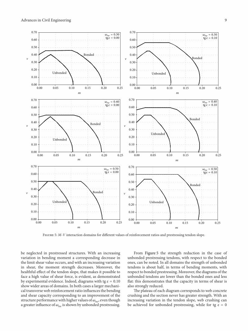

International Journal of
AerospaceEngineeringHindawi Publishing Corporationhttpwwwhindawicom Volume 2014
RoboticsJournal of
Hindawi Publishing Corporationhttpwwwhindawicom Volume 2014
Hindawi Publishing Corporationhttpwwwhindawicom Volume 2014
Active and Passive Electronic Components
Control Scienceand Engineering
Journal of
Hindawi Publishing Corporationhttpwwwhindawicom Volume 2014
International Journal of
RotatingMachinery
Hindawi Publishing Corporationhttpwwwhindawicom Volume 2014
Hindawi Publishing Corporation httpwwwhindawicom
Journal ofEngineeringVolume 2014
Submit your manuscripts athttpwwwhindawicom
VLSI Design
Hindawi Publishing Corporationhttpwwwhindawicom Volume 2014
Hindawi Publishing Corporationhttpwwwhindawicom Volume 2014
Shock and Vibration
Hindawi Publishing Corporationhttpwwwhindawicom Volume 2014
Civil EngineeringAdvances in
Acoustics and VibrationAdvances in
Hindawi Publishing Corporationhttpwwwhindawicom Volume 2014
Hindawi Publishing Corporationhttpwwwhindawicom Volume 2014
Electrical and Computer Engineering
Journal of
Advances inOptoElectronics
Hindawi Publishing Corporation httpwwwhindawicom
Volume 2014
The Scientific World JournalHindawi Publishing Corporation httpwwwhindawicom Volume 2014
SensorsJournal of
Hindawi Publishing Corporationhttpwwwhindawicom Volume 2014
Modelling amp Simulation in EngineeringHindawi Publishing Corporation httpwwwhindawicom Volume 2014
Hindawi Publishing Corporationhttpwwwhindawicom Volume 2014
Chemical EngineeringInternational Journal of Antennas and
Propagation
International Journal of
Hindawi Publishing Corporationhttpwwwhindawicom Volume 2014
Hindawi Publishing Corporationhttpwwwhindawicom Volume 2014
Navigation and Observation
International Journal of
Hindawi Publishing Corporationhttpwwwhindawicom Volume 2014
DistributedSensor Networks
International Journal of