research and exploration of stone settings
TRANSCRIPT

Rochester Institute of TechnologyRIT Scholar Works
Theses Thesis/Dissertation Collections
5-1-1972
Research and Exploration of Stone SettingsJonathan O. Parry
Follow this and additional works at: http://scholarworks.rit.edu/theses
This Thesis is brought to you for free and open access by the Thesis/Dissertation Collections at RIT Scholar Works. It has been accepted for inclusionin Theses by an authorized administrator of RIT Scholar Works. For more information, please contact [email protected].
Recommended CitationParry, Jonathan O., "Research and Exploration of Stone Settings" (1972). Thesis. Rochester Institute of Technology. Accessed from
RESEARCH AND EXPLORATION OF
STONE SETTINGS

RESEARCH AND EXPLORATION OP
STONE SETTINGS
BY
JONATHAN 0. PARRY
Submitted to the Faculty of the School for American
Craftsmen in partial fulfillment of the re
quirements for the degree of Master
of Pine Arts at Rochester
Institute of Technology
May 1972
111

Missing Page

PREFACE
The purpose in writing this thesis is to pre
sent a single source of information concerning the
construction of basic stone settings for the metals
student. Because each stone setting described may
have a great number of variations, its description
is technically oriented, primarily to the construc
tion of each setting.
Settings included are those that require a mi
nimal amount of specialized equipment and only basic
tools. Thus, although beaded and milgrain settings
are widely used by commercial stone setters, they
are not described, because beading and milgrain tools
are not always available to the student.
v

ACKNOWLEDGEMENTS
I wish to take this opportunity to express my
thanks to all who have helped me to reach this goal.
Many have contributed generously with their guidance
and friendly support, but most of all I wish to
thank Stanley Lechtzin for a sound foundation in my
basic understanding of stone setting, and Albert
Paley for help and guidance to advance with the use
of that understanding and knowledge.
VI
INTRODUCTION
The settings described in this thesis are not
geared to a beginning student, but to the advanced
student with a good understanding of working with
metals. Basic technical terms and concepts such as
fire scale, pickling, polishing, refining, scratch
brushing, solder crystallization and flowing quali
ties are not discussed; but it is assumed that the
serious student is aware of the importance of termi
nology and therefore will review if necessary.
The procedures outlined for these stone setting
methods are adaptable to personal working habits, and
are meant to be guides, not restrictions. The crafts
man is encouraged to use his own ingenuity in modify
ing the techniques to suit his own needs.
In constructing settings I myself prefer to re
fine each component before assembling in order to keep
fire scale at a minimum and to insure a strong soldered
seam, but the student is encouraged to develop his
own means of dealing with ithis and other such techni
cal problems.
VI L

FRONTISPIECE
Eight-Prong Cast Setting
vi-ii

LIST OF ILLUSTRATIONS
Page
Frontispiece: Cast Eight-Prong Setting vj_ii
Fig. 1. Straight Post Setting 7
Pig. 2. Cup and Post Setting9
Fig. 3. S-Post Setting u
Fig. 4. Threaded Post Setting*
13
Fig. -45. Split Post Setting -, g
Fig. 6. Wrapped Wire Setting _ 18
Fig. 7. Bezel for Mowabi Pearl20
Fig. 8. Tube Setting 22
Fig. 9. Simple Bezel27
Fig. 10. Simple Bezel with Bearing Strip 31
Fig. 11. Hammered Bezel Setting53
Fig. 12. Modified Bezel Setting 35
Fig. 1 3. Crown Bezel Setting
Fig. 14. Simple Double Bezel Setting 40
Fig. 15. Double Bezel of Preformed Tubing^3
Fig. 16. Cup Bezel Setting 47
Fig. 17. Half Sphere Bezel..... 49
Fig. 18. Simple Square Bezel55
Fig. 19. Triangular Bezel Setting 60
Fig. 20. Reverse Bezel Setting g^
Fig. 21. Round Fabricated Prong Setting 67
Fig. 22. Square Prong Setting 70
Fig. 23. Pattern for Making a Cone nA
IX

Fig. 24. Cone Prong Setting 75
Fig. 2 5. Two-Prong Setting 79
Fig. 26. Four-Prong Setting 82
Fig. 27. Fabricated Tension Setting 35
Fig. 28. Cast Gypsy Setting 95
TABLE OF CONTENTS
Page
Prefacev
Acknowledgements
Introduction vii
List of Illustrations j_x
BASIC INFORMATION
Stone Cutting Information 1
Commonly Used Tools 3
Common Stone Sizes and Shapes 4
POST AND WIRE-WRAPPED SETTINGS
Introduction c
Cements5
Straight Post Settings 6
Cup and Post Settingsg
S-Post Settings 10
Threaded Post Settings... 12
Split Post Settings 14
Wire-Wrapped Settings. 17
Bezel Settings for Pearls 19
Tubular Settings for Drilled Stones.... 21
Summary 23
BEZEL SETTINGS
Introduction 24

Page
Simple Bezel 25
Simple Bezel with Bearing Strip28
Hammered Bezel52
Modified Bezel 34
Crown Bezel 36
Double Bezel 38
Double Bezel of Preformed Tubing 41
Double Bezel of Fabricated Tubing ..44
Cup Bezel 4 5
Half Sphere Bezelaq
Octagon Bezel.50
Pear or Teardrop Bezel 51
Simple Square Bezel ,cn
Square Bezel with Bearing 56
Triangular Bezel 58
Keverse Bezelg-|
Summary g^
FABRICATED PRONG SETTINGS
Round Prong Settings 6 5
Square Prong Settings 68
Cone Prong Settings 71
Two-Prong Settings with Bearing 77,
Four-Prong Settings. 80
Tension Channel Settings g,
MECHANICAL SETTINGS
Reverse Riveted Settings 86
Tubular Riveted Settings 88
Page
CHEMICAL FUSION SETTINGS
Epoxy Settings 9
CAST SETTINGS
Simple Cast Settings 91
Cast Channel Settings... ?92
Cast Prong Settings...................... 93
Cast Gypsy Settings ,94
Soldered Collar Settings.. 96
INLAID SETTINGS
Terazzo Settings 98
Delrin Settings 98
Conclusion 100
References. 101

BASIC INFORMATION
Stone Cutting Information
Cut stones fall into the basic categories of
cabochons and faceted stones.
Cabochons generally have a domed top and a flat
or slightly domed back. Commonly they are round or
oval, but are occasionally of angular outline and may
be high or almost flat. Since the cut does nothing
to enhance the brilliance of a transparent stone ,it
is generally used for opaque or translucent stones,
and is excellent for displaying chatoyance as in cats-
eye mineral.
Faceted stones are usually transparent, since
the cut consists of covering parts of the surface
with tiny angled planes in a set pattern to show off
and increase the ability of the stone to refract light,
which gives it life and sparkle. The facets are ground
at predetermined angles to take the best advantage of
the refractive index of the mineral being cut; thus
certain cuts are traditional and the better the quali
ty of faceting, the more the brilliance of the stone
is displayed.
Each type of gem has a particular hardness by
nature of its mineral constitution, and these are for
convenience rated on a hardness scale of one to ten,
the softest materials at the low. end of the scale.
Moh's Hardness Scale
1. Talc 6. Orthoclase
2. Gypsum 7. Quartz
3. Calcite 8. Topaz
4 . Fluorite 9. Corundum
5. Apatite 10. Diamond
The majority of cut stones used in jewelry are of a
hardness of 5 or better byMoh'
s scale, since softer
stones like fluorite are usuallytod*
soft to with
stand wear unless given special consideration in the
design of the setting.

Commonly Used Tools
The following list is considered basic for pro
ducing the settings described in this thesis with
professional skill, although the student may be able
to circumvent the lack of a tool by ingenuity in some
instance.
Saw
Bench pin
Leather mallet
Chasing hammer
Snips or scissors for cutting solder
Ring mandrel
Soldering pick
Dapping block and tools
Rectangular chasing tool (Can be made from a
rectangular needle file by grinding off the
broken end and polishing a square end on the
file)
Binding wire
Assorted polishing and grinding papers, emory
paper
Assorted files
Jeweler's pliers
Asbestos pad
Coiled asbestos pad or charcoal block

??v|R ?0x1,18x13 18x9 16x9 16x8
?-1x10. 16x12 18x13 lSx14
11x9
9rv1 C'X1
25x18
25x19
24x14 14x10
7xCJ 16x8
30x22
1 2::10
40x30
12x10
1 5x1 1 1 4x1 2 1 4x1 0
4X12
16x12
16-1
16x1

POST AND WRAPPED SETTINGS
Introduction
Pearls and beads can be used as a central theme
for a piece of jewelry itself. Pearls are not very
durable and are easily damaged by heat and common
chemicals such as alcohol and ammonia. Thet are very
soft and are easily scratched if not well protected,
so the setting of pearls is always a last step in
finishing a piece of jewelry. Post and wrapped set
tings discussed in t; is section are adaptable to any
drilled or irregular stones, but are most commonly
used for setting pearls.
Cements
Over the years many types of stone cements have
been invented of natural, and more recently, of synthe
tic materials. The most reliable at present is epoxy,
generally bought as a hardener and a resin in separate
tubes. These are mixed according to instructions on
the tubes, and are then ready for use. An epoxy sol
vent which will not damage pearls is available. If
the slow setting type is used, hardening can be hastened
by placing the completed piece in an oven for about 20
minutes at 125 degrees Fahrenheit. A quick setting
(five minute) variety is also available.

Straight Post Setting; for Half Drilled or
Full Drilled Pearls or Other
Drilled Stones
1 . A wire is soldered with easy solder to the piece
of jewelry where the pearl is to be set. This wire
is the post, and it should be the same diameter as
the drilled hole in the pearl oi stone.
2. When the rest of the piece is completely finished,
the pearl or bead is then epoxied to*the post using
a small aiount of clear epoxy.
3. This setting can be used for full drilled pearls
or beads by addition of a beaded and polished wire
inserted at the opposite end of the hole, making a
polished dot of metal to plug the opening.

-b.
Fig. 1: Straight Post
Cross section before setting drilled pearl or stone
a. drilled pearl
b. post

8
Cup and Post Setting: for Half Drilled or
Full Drilled Pearls or Other Stones
This setting gives the pearl more protection
than the simple post setting, as the cup may be made
as deep as desired. See Figure 2.
1 . Dap a cup from 20-24 gauge metal to snugly fit
'the bottom of the pearl.
2. Solder a post of the correct diameter to fit the*
drilled hole to the middle of the inside of tye cup.
The setting is now ready to be incorporated into the
piece of jewelry.
3. When the rest of the piece is entirely finished
the pearl or bead is affixed to the post in the cup,
using a small ,amount of epoxy. If desired, a full
drilled hole may be finished by inserting a wire with
Polished bead into the exposed end.

4a.
TS C.
Fig. 2: Cup and Post
Gross section before setting pearl
a. pearl or stone
b. post
c . cup

10
S-Post: for Half Drilled Pearls or Beads
This is a stronger setting than the straight
post if the S curve is bent so the wire touches both
sides of the drilled hole. It is also useful when
the available wire is smaller in diameter than the
hole in the stone or pearl. Refer to Figure 3.
1. A wire smaller in gauge than the diameter of the
drilled hole is soldered with easy solder to the
piece of jewelry where the pearl is to be set.
2. The post is bent to have a slight double or S-
shaped curve in the wire.
3. When the piece of jewelry is otherwise completely
finished, the pearl or bead is affixed to the post
with a tiny amount of epoxy.

11
b.
Fig. 3: S-Post
Before setting half drilled pearl or stone
a, pearl
b. S-post

1 2
Threaded Post Setting: for Half Drilled Pearls
1 . Select wire the exact diameter as the drilled hole
in the pearl for snug fit, and using a tap and die set
thread the wire. See Figure 4.
2. Solder the threaded wire to the piece of jewelry
where the pearl is to be set.
3. When the piece of jewelry is finished, set the pearl
by introducing a tiny amount of epoxy into the drilled
hole and then screwing it firmly down the wire to its
base.

13
a.
b.
F ig . 4 : Threaded Post
Cross section before setting pearl
a. pearl shown in cross section
b. threaded post

14
Split Post Setting: for Half Drilled Pearls
This setting is usually reserved for large and
expensive pearls. Once the pearl is set, it cannot
be removed from the setting without risk of damage
to the pearl.
1. The hole drilled in the pearl should be 16 or 18
gauge.
2. Using a small burr, insert it in the drilled hole
and rotate it to grind out a space the shape of an
inverted cone with the widest part of the cone at the
center of the stone. See Figure 5.
3. Select for the post wire of the same gauge to fit
snugly in the mouth o'f the drilled hole. Measure the
radius of the pearl and use an 8/0 saw blade to split
the end of the wire lengthwise down to a distance from
the end not less than the radius of the pearl.
4. Using a scrap of the same wire the post is being
made from, file out a tiny wedge which should be shor
ter than the saw cut in the wire, and approximately
1/4 to 1/3 the thickness of the wire.
5. Solder the post to the proper position in the piece
of jewelry.
6. When the rest of the piece of jewelry is completely
finished, set the wedge into the slit in the post so
that the point of the wedge forces the two halves of
the post apart and a straight edge of the wedge is
uppermost. See Figure 5.

15
7. Introduce a tiny amount of epoxy into the drilled
hole and set the pearl in position on top of the
post and wedge.
8. Gently but firmly push the pearl down the post.
As it descends it will push the wedge into the saw
cut, forcing the halves of the post to spread apart.

16
Fig. 5: Split Post
Cross section before setting pearl
a. pearl
b. wedge
c. post

17
Wrapped Wire Setting for Baroque Double Pearls
This setting is most practical for double or
twinned baroque pearls, which need not be perfectly
symmetrical.
1. The wire used to wrap the pearl should be propor
tional to the size of the pearl, as it will fully show.
The tapered part of the wire should be long enough to
wrap twice around the waist of the pearl.
2. File the wire to gradually taper t3 the tip. This
portion will encircle the pearl.
3. The heavier stem of the wire is soldered, linked,
or otherwise attached to the piece of jewelry.
4. When the remainder of the piece of jewelry is com
pletely finished, the tapered end of the wire is
wrapped around the narrow center portion of the pearl.
This process can be started using pliers, but should
be finished by hand to avoid damage. Tightening the
wire by tools can cause the pearl to break. A tiny
amount of epoxy spread under the wire can be used to
keep the wire from slipping or turning on the pearl,
but excess should be avoided.

18
Fig. 6: Wrapped Wire Setting After Setting Stone
a. pearl
b0 tapered wire

19
Bezel Setting for Mowabi Pearl
Mowabi pearls are pearls that have grown at
tached to the side of the shell. Often they are
very large with flat backs and rounded tops. Due
to their large size and peculiar shape they are advan
tageously set in bezels of fine silver or thin ster
ling. If it is desirable to make a true bezel, fol
low the directions under Simple Bezel.
1. Use square wire of 16-20 gauge to make a circle
which fits snugly around the perimeter of the pearl
without pressure.
2. Solder the squared ends of the wire together
smoothly.
3. Solder the closed circle into position on the piece
of jewelry, and refine as necessary.
4. When the piece of jewelry is otherwise completely
finished, a thin coating of epoxy is spread on the
plate of the setting and the pearl pressed into posi
tion. For added protection, a post may be soldered
to the center of the setting and fitted to a drilled
hole in the pearl before epoxy is used.

20
&
F ig . 7 : Bezel for Mowabi Pearl
Cross section before setting
a. pearl
b. square wire bezel

21
Tube Setting: for Half Drilled Pearls
(Adaptable to Full Drilled Pearls)
This setting uses two similar pearls back with
a- short length of tubing separating them. Seamless
tubing is most satisfactory, but fabricated tubing
can be used as desired. See Figure 8.
1. Select or make tubing approximately 1/3 the dia
meter of the pearl.
2. The length of the piece of tubing determines the
distance between the two pearls. Using a tubing cut
ter or a saw and file ,cut the ends of the tubing
exactly at right angles to the length.
3. At each end of the tubing the lining is filed at
an angle toward the center so that a smooth flat
plane is adjacent to the pearl's convex surface.
4. The tubing is then soldered in place on the piece
of jewelry, allowing space for a pearl at each end.
5. When the remainder of the piece is completed, cut
a length of wire the same gauge as the drilled holes
in the pearls, to form a post. The length of the post
should be the length of the tubing plus the diameter
of one pearl.
6. Cement the post into one of the pearls using epoxy.
When the epoxy has set,run the wire through the tu
bing, and epoxy the other pearl to the other end of
the post. The pearls should be pushed on to fit snug
ly against the tubing.

22
b.
'c:
Fig. 8: Tube Setting
Side view after setting
a. pearl
b. tubing
c . post
23
Summary
In this section, eight methods of setting
pearls and beads have been described. Many varia
tions are possible , limited mainly by suitability
to the particular piece of jewelry. There can be no
arbitrary ruling as to what is a wrong way or a
right way to set a pearl. If the pearl is secure
ly protected and is set so as to most*
advantageously
fulfill its role as an integral part of the design,
it stands to reason that it has been set "right".

BEZEL SETTINGS
Introduction
Bezel settings can be used for both faceted
and cabochon stones. The setting usually completely
surrounds the stone, giving it maximum protection a-
gainst chipping along the edge. A bezel is usually
constructed from two separate pieces of metal, one
which froms the bearing on which the stone sits, and
another which holds the stone in place.
Bezel set stones can be used in many ways,
ranging from modular groupings down to single jeweled
accents. Generally they can be used in all forms of
jewelry because of the strength and protection af
forded by such a setting.
24

25
Simple Bezel Setting: for Basically Round or Oval
Cabochons (Adaptable to Other Shapes)
1 . Using 20-24 ga. metal, cut a strip of metal long
enough to go around the circumference of the stone
at its base and approximately 1/4 the height of the
stone.
2. Carefully form this strip of metal to the circum
ference of the stone at its base, being careful not
to mark the metal. Saw the strip where the ends over
lap in such a way that the stone fits snugly inside,
and the ends of the metal strip butt together per
fectly.
3. Solder the ends of the strip together smoothly,
using hard or medium solder.
4. If the bezel fits loosely, the seam must be sawed
open, and the strip trimmed to fit and resoldered.
If the bezel is too tight, it can be planished slight
ly on a ring mandrel until it will slip over the stone
base,without forcing.
5. Using a flat plate of metal 20 ga. or heavier, saw
out a piece slightly larger than the bezel, and solder
the bezel to its surface.
6. After soldering, remove the excess metal projecting
outside the bezel.
7. Polish the bezel and incorporate it into the piece
of jewelry as planned.
8. Use a burnisher to gently push and smooth the bezel
against the sides of the stone after it has been in-

26
serted in the setting. The piece of work should be
firmly supported so pressure on the stone is firm
and evenly distributed while working on it ; other
wise, sudden changes in pressure may crack or dislodge
the stone or make large dents or lumps in the bezel
which will be difficult to burnish smooth.

27
A.
-S~b,
B.
Fig. 9: Simple Bezel in Cross Section
A -n
B. Bezel after setting stone
a. stone
b. bezel
c. plate

28
Simple Bezel Setting With Bearing Strip:
for Round or Oval Stones
1. Select a strip of metal 22 gauge, approximately
the width of the bezel desired and slightly longer
than the circumference of the stone at its base. A
second strip the same length, of 19 gauge and about
2/3 as wide will also be needed for the bearing.
Both strips must be annealed and pickled.
2. The 22 gauge strip must now be made to fit as tight
ly as possible around the stone at its graatest girth.
This can be accomplished in many ways: only one way
is described here. Make a mock bezel from a strip of
paper the same size as the 22 gauge strip and cut it
to fit perfectly the girth of the stone, butting the
ends. Then using this paper strip as a template, add
twice the thickness of the metal and scribe a line oni
the metal strip being sure that the strip is marked
exactly at right angles to the axis of the strip.
Saw the 22 gauge strip at the scribed line to make a
square end.
3. Using half round pliers, gently form the strip in
to a circle or oval with the ends tightly butted to
gether. The plier jaws may be taped to reduce scratch
ing the bezel, but too much force will mark the bezel
in spite of padding.
4. Solder the bezel from either the inside or the
outside, using hard (#10) or medium (#30) solder.
Pickle and refine.

29
5. The bezel should now be shaped oyer a ring man
drel, using a leather mallet until it neatly and
snugly fits around the stone. If it is too small
it can be planished slightly; if it fits loosely the
seam should be opened, the excess removed, and the
joint resoldered.
6 . Steps 1-5 are now repeated in making the bearing
from the narrower strip, with a modification as fol
lows. Using a strip of paper as before, find the
exact length of the inside of the bezel, saw the
19 gauge strip slightly shorter than the paper, and
form it to fit tightly inside the bezel.
7. Solder and refine the bearing, using the same grade
of solder as previously used on the bezel.
8. If the stone being set has a flat bottom, the out
side edge of the bearing should now be filed at a
slight angle, so that when soldering in the next step
the solder will fill the gap without flowing up the
side of the bezel and thus creating a curved fillet.
See Figure 10A.
If the stone being set has a convex bottom or
is faceted, the bearing must be filed on the inside
as well as the outside so that a sharp edge does not
lie against the stone.
9. The bezel should be placed on a flat surface to be
soldered. The bearing is slipped inside, care being
taken that it is level with the bezel at the lower
edges. Tiny paillons of medium or easy solder are now

30
set in the groove between the bearing ahd the bezel.
Solder, taking care not to allow the solder to flow
up the side of the bezel. Pickle and refine.
10. The bezel is now ready to be incorporated into
a piece of jewelry. Setting the stone should not be
attempted until all other processes are completed.
11. When the piece of jewelry is completely finished
otherwise, then the stone should be set in the bezel
as follows.
The piece and bezel should be supported in some
way so that the pressure exerted during burnishing
will not distort the piece. using a curved burnisher,
begin to push the bezel over the stone, working even
ly and alternately on all sides. Do this slowly, a
little at a time, to avoid wrinkling the metal. When
the bezel is curved inward sufficiently to hold the
stone in place without play, burnish the bezel until
smooth and firmly in contact with the stone at all
points around the circumference. See Figure 10B.
12. Select or prepare a barrette file which has had
the edges ground smooth to prevent scratching the
stone, and file the top edge of the bezel. The rest
of the bezel may be left burnished or it may be po
lished if polishing compound will not mar the stone.
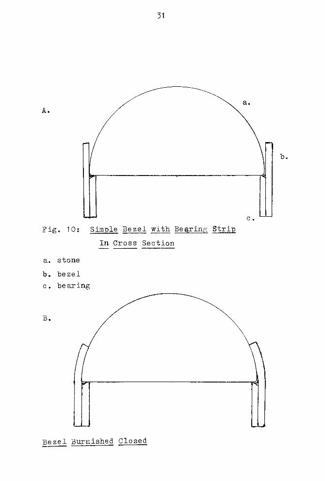
31
A.
F ig . 10: Simple Bezel with Bearing Strip
In Cross Section
a. stone
b. bezel
c. bearing
B.
Bezel Burnished Closed
32
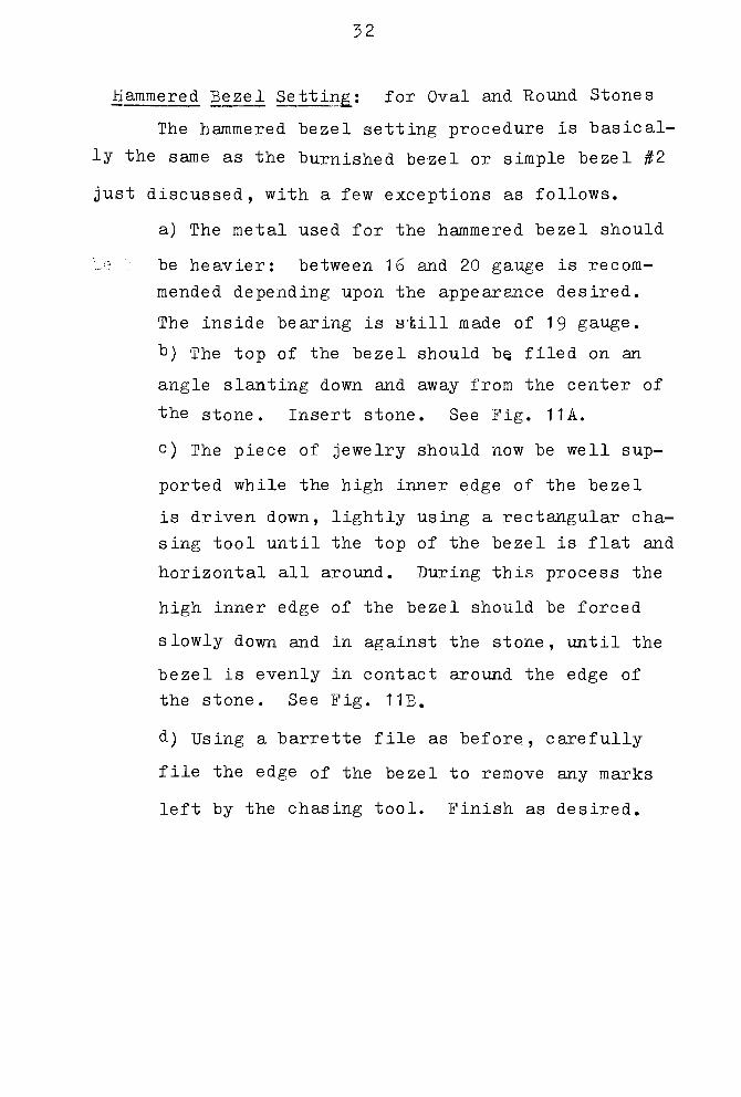
Hammered Bezel Setting: for Oval and Round Stones
The hammered bezel setting procedure is basical
ly the same as the burnished bezel or simple bezel #2
just discussed, with a few exceptions as follows.
a) The metal used for the hammered bezel should
Eq .4 be heavier: between 16 and 20 gauge is recom
mended depending upon the appearance desired.
The inside bearing is still made of 19 gauge.
b) The top of the bezel should be, filed on an
angle slanting down and away from the center of
the stone. Insert stone. See Fig. 11 A.
c) The piece of jewelry should now be well sup
ported while the high inner edge of the bezel
is driven down, lightly using a rectangular cha
sing tool until the top of the bezel is flat and
horizontal all around. During this process the
high inner edge of the bezel should be forced
slowly down and in against the stone, until the
bezel is evenly in contact around the edge of
the stone. See Fig. 11B.
d) Using a barrette file as before, carefully
file the edge of the bezel to remove any marks
left by the chasing tool. Finish as desired.

33
A.
^- b,
Fig- 11: Hammered Bezel Setting In Cross Section
a. stone
b. bezel
c. bearing
B.
Bezel After Being Set

34
Modified Bezel Setting: for Oval and Round
Stones, Adaptable to Other Shapes
The procedures in making this setting are the
same as for making the burnished setting (simple
bezel type #2) up to the point of soldering the
bezel to the piece. Before incorporating the bezel
into the design, parts of the bezel are removed by
filing or sawing down to just above the bearing level.
See Fig. 12. Care should be taken to cut into
the bearing or expose the lower edge of the stone
unless this has been given previous careful consi
deration. Hardness and durability of the stone as
well as the usage of the piece should be given
thought, since by removing part of the bezel and
bearing, the risk of damage to !;the stone from wear is
greatly increased.

35
1
'E^^
' \^*-^V.
t
1
!-4" "
* ,
i t
i
i_iii-
i
i
p-\
*
i
Fig. 12: Modified Bezel Setting;
After Setting
a. stone
b. bezel
c. bearing
Side View

36
Crown Bezel Setting: for Round or
Oval Faceted Stones
The procedure in making a crown bezel is the
same as making a simple bezel with bearing as pre
viously discussed, up to the point where the bezel
is incorporated into the piece of jewelry. Before
soldering the bezel to the piece, prongs are made by
filing or sawing away parts of the bezel and bearing
to allow light to come up through the ^faceted stone.

37
d.
<-
k.a.
tb.
Fig. 13: Crown Setting
Side view
a. bezel
b. bearing
c. bearing
d. prong
38
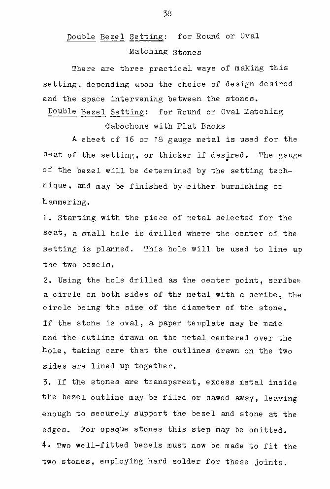
Double Bezel Setting: for Round or Oval
Matching stones
There are three practical ways of making this
setting, depending upon the choice of design desired
and the space intervening between the stones.
Double Bezel Setting: for Round or Oval Matching
Cabochons with Flat Backs
A sheet of 16 or 18 gauge metal is used for the
seat of the setting, or thicker if desired. The gauge
of the bezel will be determined by the setting tech
nique, and may be finished by either burnishing or
hammering.
1 . Starting with the piece of metal selected for the
seat, a small hole is drilled where the center of the
setting is planned. This hole will be used to line up
the two bezels.
2. Using the hole drilled as the center point, scribes
a circle on both sides of the metal with a scribe, the
circle being the size of the diameter of the stone.
If the stone is oval, a paper template may be made
and the outline drawn on the metal centered over the
hole , taking care that the outlines drawn on the two
sides are lined up together.
3. If the stones are transparent, excess metal inside
the bezel outline may be filed or sawed away, leaving
enough to securely support the bezel and stone at the
edges. For opaque stones this step may be omitted.
4. Two well-fitted bezels must now be made to fit the
two stones, employing hard solder for these joints.

39
5. Using medium solder, affix the bezels to the seat
one at a time, lining them up with the inscribed out
lines previously made. The beael can be held in place
with binding wire or stitches to keep it from shifting
during soldering. Pickle and remove fire scale on one
bezel as co lpleted before starting the one on the re
verse side.
6. Excess metal of the plate outside the bezels should
now be removed and the double bezel is ready to be sol
dered with easy solder to the piece of jewelry.
1. Set the stones using the burnished or hammered tech
nique as described, earlier.

40
Kb.
Fig. 14: Simple Double Bezel Setting in Side View
a. stone
b. bezel before setting stone
c. bearing
d. bezel after setting stone.
41
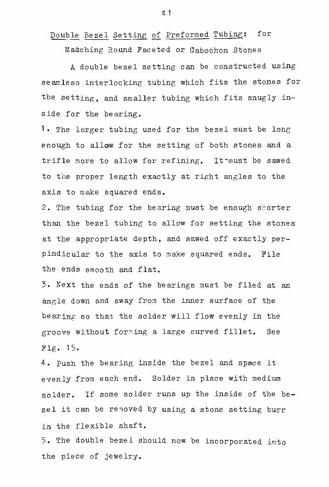
Double Bezel Setting of Preformed Tubing: for
Matching Round Faceted or Cabochon Stones
A double bezel setting can be constructed using
seamless interlocking tubing which fits the stones for
the setting, and smaller tubing which fits snugly in
side for the bearing.
1 The larger tubing used for the bezel must be long
enough to allow for the setting of both stones and a
trifle more to allow for refining. It "must be sawed
to the proper length exactly at right angles to the
axis to make squared ends.
2. The tubing for the bearing must be enough shorter
than the bezel tubing to allow for setting the stones
at the appropriate depth, and sawed off exactlyper-
pindicular to the axis to make squared ends. File
the ends smooth and flat.
3. Next the ends of the bearings must be filed at an
angle down and away from the inner surface of the
bearing so that the solder will flow evenly in the
groove without forming a large curved fillet. See
Fig. 15.
4. Push the bearing inside the bezel and space it
evenly from each end. Solder in place with medium
solder. If some solder runs up the inside of the be
zel it can be removed by using a stone setting burr
in the flexible shaft.
5. The double bezel should now be incorporated into
the piece of jewelry.

42
6. When all other operations have been completed, the
stones may be set by gently working the metal over
the stone with a burnisher. if the bezel tubing proves
too heavy to burnish, remove the stone, emory the
outer rim of the bezel until it is thinner, polish it,
replace the stone and burnish the setting over the
stone.

43
a.
F ig . 15: Double Bezel Setting ,Preformed Tubing Type
Cross Section before Setting Stone
a. stone
b. tubing bezel
c. tubing bearing

44
Double Bezel Setting Fabricated Tubing
Type : for Round or Oval Matching
Cabochons or Faceted Stones
This method is the same as the previous one
described except that a long seamed bezel and a
shorter seamed bearing are made into tubing. This
method may be necessary for larger stones when pre
formed tubing is unavailable. Hard solder should be
used to seam the bezel and thecollar,*
and medium
solder is used to solder them together. Suitable
gauges are 22 gauge for the bezel and 19 gauge for
the bearing.

45
Cup Bezel: for Round or Oval Cabochons
This setting is decorative as well as functional
and may be chosen when th side as well as the top of
the stone and setting is in prominent view.
1 A dapped cup slightly larger than the base of the
stone is formed from 20 gauge metal. The depth of the
cup should be decided in relation to the appearance
desired, as it will not affect the security of the
stone.
2. A bearing is made from 18 gauge square wire the
exact size of the base of the stone and soldered to
gether with hard solder.
3. The bearing should now be fitted to the inside of
the dapped cup. It will not reach to bottom, but
must be filed as necessary to make ample good contact
with the cup lining to allow for strong solder join
ing.
4. Using medium solder, the bearing is soldered to
the cup. Care should be taken to have it evenly cen
tered and to prevent it from slipping during the pro
cess.
5. The excess metal of the cup should now be removed
by filing or sawing even with the outer surface of the
bearing. The seam between the bearing and cup is now
exposed but will be covered in the next step. The
cut edge of the cup should be filed smooth with the
bearing so the bezel will fit tightly. See Figure 16.
6. A bezel is now made using about a 22 gauge strip

46
if a burnished setting is planned, or about 18 gauge
if a hammered setting is planned. Hard solder is used
to seam the bezel, which must fit against the bearing
and down over the cup to slightly below the level of
the cup surface .
7. The bezel is now positioned and soldered to the
cup from the bottom side of the setting. Soldering
from the top is possible, but there is more risk of
making a curved fillet which will ha"s to be removed.
8. The setting may now be incorporated into the piece
of jewelry.
9. Set the stone by the burnishing or hammering method
previously described.

47
-b.
Fig. 16: Cup Bezel Setting: Cross Section
before Setting
a. stone
b. beael
c . be ar ing
d. cup

48
Half Sphere Bezel Setting: for Round Cabochons
This setting is similar to the dapped cup set
ting with a few changes as noted here.
1 . Dap a hamisphere of 20 gauge metal, using a dap
ping block. The opening of the hemisphere should be
the correct size to admit the stone which must sit low
enough in the hemisphere to allow sufficient metal to
form a bezel to hold the stone.
2. A bearing to support the stone is ma^e of 18 gauge
square wire. It should be the exact size as the base
of the stone and soldered together with hard solder.
See Figure 17.
3. The outer edge of the bearing must fit tightly
against the inside of the hemisphere, so the bearing
will have to be filed at an angle around its outer
lower border. When filing is completed, the bearing
wire will 'be practically triangular in cross section
and it will sit level in the cup.
4. The bearing is next soldered into position with
easy solder, care being taken to present its shifting
position.
5. The half-sphere setting is now incorporated into
the piece of jewelry.
6 If necessary, the outer rim of the bezel may be
filed at an angle down and away from the center of the
stone in order to make the edge thinner for burnishing.
This step would be unnecessary for a hammered setting.
Complete the setting of the stone as in earlier dis-

49
Fig. 17: Half Sphere Bezel Setting
Cross section before setting stone
a. stone
b. dapped half sphere
c . be ar ing

50
cussion.
Octagon Bezel Setting: for Faceted or
Cabochon Octagon Stones
This setting is a modification of the round be
zel setting, except that the bezel and the bearing are
made slightly smaller than the stone and then shaped
on an octagon bezel mandrel. During the shaping, they
are stretched sufficiently to fit the stone properly.
1 Use a metal strip of 20 gauge to mak a soldered
bezel slightly smaller than the circumference of the
stone. The bezel is worked over an octagon bezel man
drel until it fits the stone perfectly.
2. In a similar fashion, a bearing of 18 gauge sol
dered to fit the bezel before stretching is now also
stretched over the octagon bezel mandrel, until it
fits snugly inside the shaped bezel.
3. Solder the bearing inside the bezel.
4. Refine the setting as needed and set the stone by
the standard burnishing or hammering methods already
discussed.
51
Pear Shaped Bezel Setting; for Faceted or
Cabochon Pear or Teardrop Shaped Stone
The pear bezel is another modification of the
round bezel, and is constructed following the same
directions. The bezel is shaped by jeweler's pliers
which may have the jaws taped to avoid marking the
rnetal. The site for soldering may be at the pointed
end for narrow stones or on one side for wider stones,
Setting the stone and completing the setting is the
same as for the round bezel.

52
Simple Square or Rectangular Bezel
getting; for Cabochons
The simple bezel described here is for square
or rectangular cabochons only. A more complex proce
dure suitable for either cabochons or faceted stones
follows.
1. Select a piece of 18 gauge sheet as large as the
stone plus a margin the thickness of the bezel. This
sheet will serve as the bearing.
2. To make the bezel, two strips of 20 gauge metal
are sawed, each slightly longer than one half the pe
rimeter of the stone, measured from one corner around
to the opposite corner. These strips should either
have been sawed from annealed metal, or must now be
annealed before proceeding further. File all four ends
at right angles to the axis of the strip to make square
ends.
3. Take one of the strips, lay it against one side of
the stone and mark the exact length of the stone from
one end of the strip, as precisely as possible. Using
the edge of a square file,file a groove across the
width of the metal strip at the marked length of the
stone. If there is any question about the accuracy
of the measurement, better too long than too short, as
the excess can be filed away. The groove should be
made at exactly right angles to the axis of the strip,
and parallel to each end so all intersections are 90
degree angles, and should be filed almost thrdlaghrthe

53
metal. Stop filing when a raised line can be seen on
the reverse side of the strip. Repeat the measuring
and filing step just described, using the second me
tal strip. See Figure 18.
4. Each strip is now bent along the groove to make a
right angle with the groove on the inside of the an
gle -
5. A single paillon of solder should be sufficient to
reinforce the inside of each angle and hold it at 90
degrees.
6. If necessary, saw or file one end of one strip so
that that side of the bezel exactly fits one side of
the stone. Repeat the fitting of the other strip,
making the adjustment to the side of the bezel which
will lie parallel to the other side already adjusted.
Thus, if the stone is rectangular, both of the short
sides have been adjusted to the stone.
7. Lay the stone flat on the working space and assem
ble the two strips to frame it, letting the two unad
justed sides project out past the corners. With all
four sides at point marked c on accompanying diagram.
"Remove the stone, realign the bezel pieces and solder
at scribed joints, using medium solder.
8. Saw off protruding ends and refine bezel.
9. Solder bezel to 18 gauge sheet bearing. Excess
metal both inside and outside the bezel may be left,
removed, pierced or treated as desired according to
54
the planned design.
10. The problems of setting the stone are greatly in
creased if the sides of the bezel are any higher than
necessary to hold the stone ; so file or grind down the
upper rim of the bezel to the lowest practical height.
1 1 . Incorporate the setting into the piece of jewelry.
12. Using a 6/0 saw blade, cut open the corners of
the bezel 2/3 of the way down to the bearing plate.
1 3. Insert the stone in the setting and burnish the
setting closed. The saw cuts should close during this
process. The setting may be left burnished or polished.

55
a.
A.
B. 1 d.
Fig. 18: Simple Square Bezel
a. bezel with filed notch
b. bezel being lined up for second soldering
c . point where line is scribed
d. cross section before setting stone

56
Square Bezel Setting with Bearing: for
Square or Rectangular Faceted or
Cabochon Stones
This bezel setting is more complex than the pre
vious simple square bezel setting because the bearing
is made like the bezel, only smaller to fit inside the
bezel. In this style the bezel must be made high
enough so that the culet of the stone is hidden from
the side view. The bezel is made from 20 gauge metal
and the bearing from slightly thicker metal.
1 . Construct the bezel following steps 2-8 under di
rections for the simple square bezel previously given.
2. Make the bearing using 18 gauge metal strip and re
peating the same procedure as in making the bezel,
keeping in mind that the bearing must fit snugly in
side the bezel when completed.
3. Chamfer the bearing to keep the solder from form
ing a curved fillet.
4. if the stone to be used is faceted, the inside edge
of the bearing also must be chamfered to make a seat
for the stone.
5. If necessary, grind or file down the upper rim of
the bezel so that the bezel will be only as high as
necessary to secure the stone.
6. The bearing and the bezel are soldered together with
easy solder, with care to keep the tops level.
7. The setting may now be incorporated into the piece
of jewelry.
8. Using a 6/0 saw blade, cut open the corners of the

57
bezel almost down to the bearing.
9. Insert the stone in the setting and burnish the
setting closed, closing the saw cuts in the process,
Leave bezel burnished or finish by polished.

58
Triangular Bezel Setting: For Faceted or
Cabochon Triangular Stone
This setting is best constructed in one piece,
making the bearing part of the bezel.
1 . Start with a strip of metal that is the approxi-
mate width of the bezel planned, and longer than the
perimeter of the stone. The gauge of this metal
should be heavier if a hammered setting is planned,
or lighter if a burnished setting is planned.
2. Solder a strip of 19 gauge metal narrower than the
bezel strip to it, using medium solder and leaving e-
nough of the bezel exposed to hold the stone in place
when it is set. It is better to leave too much bezel
exposed than not enough, because the excess can be
filed off after the setting is constructed. Be sure
the edges of the bezel and the bearing are parallel
while soldering.
3. Measuring Inxfroaa, the fend of the strip slightly
more than the length of one side of the stone, scribe
a line across the width of the bezel on the inside.
4 . Using a triangular file ,file a groove on this
scribed line which must be perfectly perpindicular . to
the length of the bezel. Continue filing through the
bearing and almost through the bezel, until a raised
line can be seen on the reverse side of the strip.
5. Scribe another line the exact length of one side
of the stone measured from the intersection of the in
ner edge of the bezel with the filed groove (point c

59
on pig. 19).
6. Using the triangular file, file another groove on
the inside of the setting and exactly perpindicular
to its axis. This second groove should not be star^
ted on the scribed line measured in the last step, but
at a point the thickness of the bezel past the scribed
line. Again, file until a raised line is visible on
the outside of the setting.
7. The section of the metal between the two grooves
will make one side of the setting. In a similar way
measure off an identical section on either side of the
finished section. These two grooves will be close to
the ends of the strip and should be filed all the way
through the setting, thus forming one half a groove
at each end, which will be joined together.
8. The strip is now formed into a triangle with the
filed grooves on the inside of the setting.
9. All three corners are now soldered on the inside
with easy solder. One paillon of solder for each
corner should be sufficient.
1 0. Incorporate the setting into the piece of jewelry.
1 1 . Insert the stone in the setting and finish setting
by the hammering method, or saw open the corners of
the setting and burnish the setting over the stone as
in doing a square bezel.

a.
>n
60
B.-n p<
Fig. 19: Triangular Bezel Setting
a. end view of bezel
b. length of one side of the stone ot be set
c.intersection of bezel and groove
d. cross section

61
Reverse Bezel Setting: for Any Shape of Cabochon
This setting can only be used when the back of
the setting is accessible, and is especially suitable
for stones on a large flat surface.
1. Select a sheet of metal 16 gauge or heavier for
the bezel. A hole is sawed in this piece which is the
shape of the base of the stone but smaller.
2. The hole is filed on an angle from the side which
will be the back toward the center of the hole. The
angle is determined by the angle of the sides of the
cabochon at its base, since the stone must fit into
the opening from the back and be flush with the back
surface, as well as fitting snugly against the sides
of the opening on the front surface. See Figure 20.
3. When the mounting is finished so that the stone
fits it well, tabs of metal are soldered to the back
of the mounting. These should be of 22 gauge so the
c an be easily worked, and three are sufficient to hold
the stone in the setting, but more may be used to make
the back of the setting decorative if this is appro
priate to the design. For the average stone each tab
should be 2 or 3 mm. in width, and they are spaced to
project far enough toward the center setting so that
they will hold and support the stone. Using medium
solder, attach the tabs flat against the back of the
plate. (For a variation see section on Rivets) .
4. The setting may now be incorporated into the piece
for which it was designed.

62
5. To set the stone, carefully bend the tabs back
using parallel jaw pliers. Bend them only enough to
allow the stone to be slipped into the setting from
the back. Once the stone is set straight, the tabs
are burnished back into place against the back of the
stone.
6 . Aivariation in setting the stone is to put a bear
ing which just fits the bottom of the stone behind or
below the stone before burnishing the tabs closed.

63
Fig. 20: Reverse Bezel Setting
Cross section
a. stone
b. setting
c . prong
d. stone after being set

6"A
Summary
There are sixteen bezel settings described in
this section. Their explanations have been kept as
simple and direct as possible,and no implication is
intended that these are absolute answers to bezel set
ting problems. Each of these settings may be varied
both in construction and design, and the craftsman
should feel free to modify according to his own work
habits. Although the designs have heert kept very
simple to avoid confusion in following the directions,
it is assumed that the craftsman may wish to elaborate
on the basic structure employing techniques of inlay,
woodgraining ,marriage of metals and other means to
enhance the design or express his individuality. Since
more elaborate techniques naturally increase the dif
ficulties, it is suggested that the basic methods des
cribed here be mastered before adding new technical
problems to the task.

FABRICATED PRONG SETTINGS
Round Fabricated Prong Settings : for Cabochons,
Round, Oval, or Pear Shapes
This setting is sturdy and easy to construct,
but does not offer much protection to the stone a-
gainst the setting itself.
1. Using 18 gauge square wire, make a bearing the
exact size of the base of the stone, making sure the
stone does not project past the edge of the bearing
at any point.
2. The ends of the square wire bearing should butt
against each other tightly, and the joint soldered
with hard solder.
3. A coiled asbestos soldering pad or a charcoal
block is needed for the next step of construction.
Saw four lengths of 18 gauge square wire, each about
2 1/2 times the length of the prongs desired.
4. With the bearing centered on the pad or block,
space the prongs as desired around the outside of the
bearing, pushing the end of each prong down into the
pad or block so it stands vertically and tight against
the bearing.
5. With each prong squarely in contact with the bear
ing use medium or easy solder to fasten them to the
bearing.
65

66
6. Remove the setting from the block and saw off the
extra length that was imbedded. Emory the bottom of
each prong and its joint to finish the bottom of the
setting.
7. The top of the prongs should now be cut to the
same length, as desired.
8. The outer side of the tip of each prong is tapered
as shown in part $ of the accompanying diagram, so
that the part to be burnished over the. stone will be
thinner.
9. The setting is now ready for use in a piece of
jewelry and may be incorporated.
10. When all else is completed, insert tne stone in
the setting, and push the prongs over the stone with
approved burnishing technique.
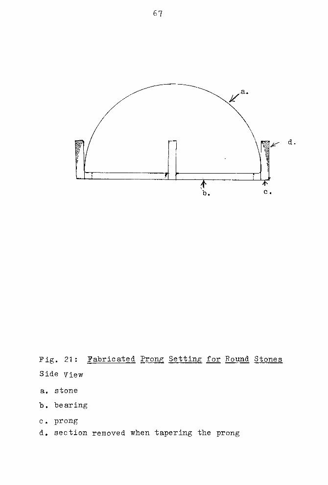
67
m*-
Fig. 21 : Fabricated Prong Setting for Round Stones
Side view
a. stone
b. bearing
c . prong
d. section removed when tapering the prong

68
Square Fabricated Prong Settings : for Square,
Rectangular, Triangular Shapes,
Adaptable to Other Shapes
Stones with corners used in this type of set
ting should be supported by a prong on each side of
any corner.
1 The bearing should be made out of annealed 18
gauge wire cut long enough to easily encompass the
perimeter of the stone.
2. Scribe a line straight across one side of the wire
very near one end of it. From this line measure in
exactly the length of one side of the stone and scribe
a second line. Repeat this procedure until each side
of the stone has been marked on the wire , working in
successive order around the stone if it has sides of
different lengths.
3. Using one corner of a triangular file, file a
groove at each scribed line deep enough so that a
raised line is detectible on the reverse side. Grooves
at each end are filed all the way through to make an
gular ends.
4. The wire is now shaped into a bearing the shape of
the stone, being careful not to break it at any of the
corners. The filed grooves are now on the inside of
the bearing.
5. Use a paillon of solder to fasten each corner on
the inside of the angle.
6. Cut two prongs of 18 gauge wire for each corner of

69
the stone of the length desired. Complete the set
ting the same wayaas for a round stone, following
steps 3-10 under that description.

70
D-^-b.
.^r a.
a.
b.
j
<-c.
Fig. 22: Prong Setting for Square or Angular Stone s
. a, bearing
b . prong
c . side view section that is removed when tapering
the prong

71
Cone Prong Setting: for Round Faceted
or Cabochon Stones
This setting is similar to the commercial crown
setting.
1 A cone is fabricated out of 20 gauge sheet metal.
This cone should be slightly smaller at its wider end
than the diameter of the stone ; that ie ,the stone
will be too large to fit into it. The angle of the
sides of the cone depend on height and visual effect
desired, since a narrow cone will form a higher set
ting than a wide cone. See Fig. 23 for making a cone.
2. The cone should be soldered closed and refined be
fore the prongs are soldered to it.
3. Depending upon the size of the stone, 18 gauge or
heavier square wire is used to make the prongs, which
are made long enough to extend from the point of the
cone out past the wide end of the cone far enough to
form a setting into which the stone will fit. See
diagram of cone setting.
4. As in the previous two descriptions, a coiled as
bestos pad or charcoal block is used to support the
cone and prongs while soldering. Stand the cone on
the block and space the prongs evenly around it, each
prong touching the cone throughout its entire length,
and one end firmly implanted in the block to hold it
in position while soldering.
5. Using medium or easy solder, solder each prong in
place.
72
6. Remove the setting from the block, saw off any
excess of each prong projecting beyond the small end
of the cone and emory smooth this end of the cone, the
prongs, and their joints.
7. Insert the stone so it sits level in the prongs
and scribe a line on the inside of each prong slight
ly below the point where the circumference of the
stone touches the prong. The stone should rest just
febove these marks.
8. Set aside the stone and file a groove straight
across each prong on the scribed line, using a trian
gular needle file. The filed groove should be about
1/3 of the thickness of the prong.
9. When all grooves are completed, the stone should
pop into the setting and rest securely, using only
gentle pressure on the stone. If the grooves are too
deep and the stone seems at all loose,remove the stone
,
squeeze the prongs slightly together and refit the
stone.
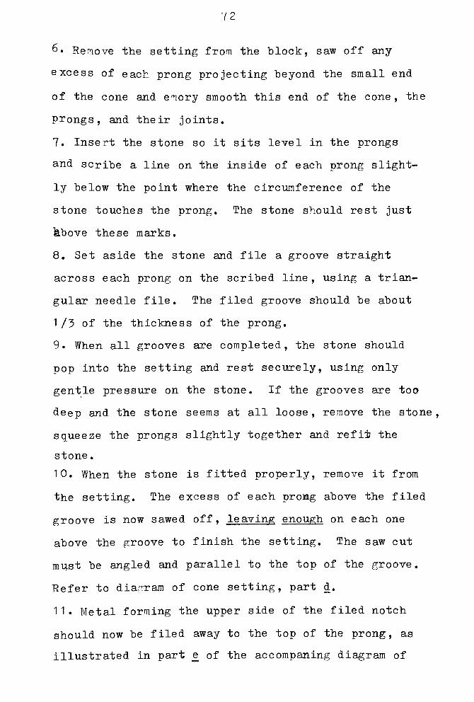
10. When the stone is fitted properly, remove it from
the setting. The excess of each prong above the filed
groove is now sawed off, leaving enough on each one
above the groove to finish the setting. The saw cut
must be angled and parallel to the top of the groove.
Refer to diagram of cone setting, part d.
11. Metal forming the upper side of the filed notch
should now be filed away to the top of the prong, as
illustrated in part e of the accompaning diagram of

73
a cone setting, to allow for pushing the prong over
the stone.
12. The setting is now ready to be incorporated into
the piece of jewelry.
13. After the stone is securely seated in the notches
without undue strain on the stone, a chasing tool
c an be used to start the prong over, and a burnisher
to finish tightening the prongs.

74
i.
-*jb. *l
Fig. 23: Pattern for Cone
a. size of desired cone
b. size of pattern
c .center of cone

75
A.
b.
d.
B.
Fig. 24: Cone Prong Setting
A. side view
a. cone
b. prong
c. bearing
B# cl. angle at which excess is removed
0. e. final shape of prong

76
Two-Prong Setting with Bearing: for Round or
Oval Faceted Stones, Adaptable
to Other Shapes
Only two prongs are needed to hold the stone in
place, and the bearing keeps the stone from moving.
This setting is not recommended for rings because of
the wear to which they are subjected.
1. A bearing is made to support the stone, from 14-16
gauge sheet metal, using heavier metal for a larger
stone. The piece of sheet metal should be large
enough to permit handling while sawing it to the size
of the stone. At the point which marks the center of
the projected setting, a hole is drilled or pierced.
The diameter of the hole should be the diameter of
the stone minus twice the thickness of the sheet metal.
2. If the stone is round, using a stone setting burr
the exact size of the stone girdle,cut open the
drilled hole until the girdle of the stone will sit
flush with the surface.
3. Saw around the outside of the opening, staying as
close as possible to the edge of the burred portion
without cutting into it. This should result in pro
duction of a metal ring which is triangular in cross
section, whose outside diameter is the same as the
stone, and whose inside border is slightly smaller
and angled to fit the sides of the stone supporting
the girdle.
4. File and refine the outside edge of the bearing.

77
When the stone is placed in the bearing, no part of
the metal should project outside the circumference
of the stone.
5. Note: If the stone is any other shape than round,
the inner border of the bearing cannot be formed by
use of the stone setting burr, but will have to be
filed at the proper angle by hand in a bearing fabri
cated out of square wire.
6. Use 14-16 gauge sheet metal to make the prongs and
decorative part of the setting. The inside opening
formed by the prongs must be exact so that the bear
ing will just fit within the opening supported by a
shelf, and fit snugly against the parts that will be
come the prongs. Refer to the illustration of two
prong setting.
7. The bearing is now soldered in place in the setting
with medium solder and the setting is refined.
8. The setting is now ready to be incorporated into
a piece of jewelry.
9. After all other operations are completed, the prongs
are cut. Using a 6/0 saw blade, two prongs are cut by
sawing straight down from the top of the bezel to a
Point just above the bearing. The thickness of the
prong should be the same as the thickness of the metal.
Refer to diagram of two-prong setting, part d.
10. Insert the stone in the setting and start the
prongs over using a knife blade. Finish working the

78
prongs down with a burnisher. The prongs should not
extend past the first row of facets. If the stone is
still a little loose in the setting after the prongs
are down, the bearing may be burnished up slightly
to tighten it.

79
A.
B.
b.
Fig. 25: Two-Prong Setting with Bearing
A. side view B. end view
a. bearing
b. sheet prong
c . bearing seat
d. saw cut for prong
e.stone

80
Four-Prong Setting: for Round, Oval, Square or
Emeraldshapes, Adaptable to Other Shapes
This setting should be fabricated from heavy
sheet metal, such as 12-16 gauge. This procedure is
adaptable to a six, eight, ten-prong setting, or lar
ger.
1 Cut a paper pattern the size and shape of the set
ting desired. The inside diameter of the opening of
the setting must be the size of the stone minus twice
tne thickness of the sheet metal employed. See the
accompanying diagram.
2. Cement together two sheets of metal the same gauge.
These pieces should be large enough to allow for hand
ling while sawing out the setting. Cement the paper
pattern to the center of the double thickness of
sheet metal.
3. Before separating the two sheets, file the edges
of the prongs and refine the setting. Using a rectan
gular needle file, at this time start the seat for the
stone. Using a triangular file, continue filing the
seat for the stone. See illustration of four-prong
setting. The opening between the prongs must be just
large enough for the stone to fit between the prongs.
5. Separate the two sheets of metal and on each piece
scribe a line which divides the setting into mirror
halves.
b. On one of the pieces saw a rectangular notch the
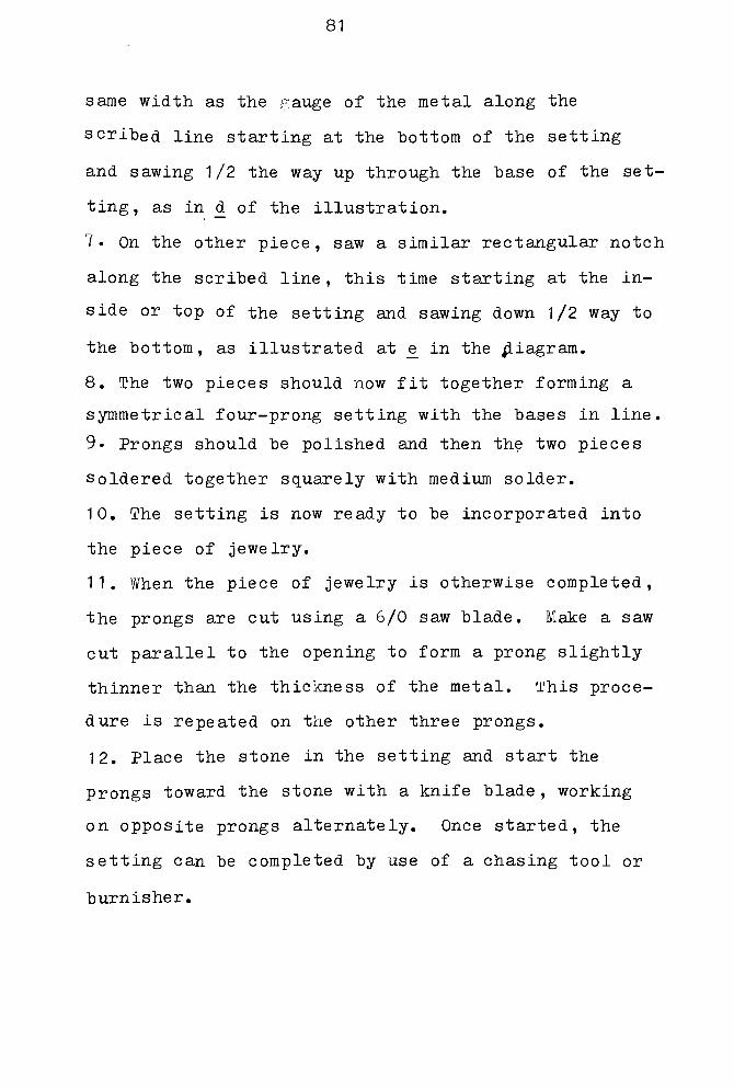
81
same width as the gauge of the metal along the
scribed line starting at the bottom of the setting
and sawing 1/2 the way up through the base of the set
ting, as in d of the illustration.
7. On the other piece, saw a similar rectangular notch
along the scribed line , this time starting at the in
side or top of the setting and sawing down 1/2 way to
the bottom, as illustrated at e_ in the diagram.
8. The two pieces should now fit together forming a
symmetrical four-prong setting with the bases in line.
9. Prongs should be polished and then the two pieces
soldered together squarely with medium solder.
10. The setting is now ready to be incorporated into
the piece of jewelry.
11. When the piece of jewelry is otherwise completed,
the prongs are cut using a 6/0 saw blade. Make a saw
cut parallel to the opening to form a prong slightly
thinner than the thickness of the metal. This proce
dure is repeated on the other three prongs.
12. Place the stone in the setting and start the
prongs toward the stone with a knife blade , working
on opposite prongs alternately. Once started, the
setting can be completed by use of a chasing tool or
burnisher.

82
a.
Fig. 26: Fabricated Four-Prong Setting
Side view before assembling
a. stone c. bearing
b. prong d. & <fc. notch for assembling

83
Fabricated Tension Setting: for Square or
Rectangular Stones, Adaptable to
Other Shapes.
This settings is adaptable to almost any type
of jewelry. The basic principle is that the stone is
held between two sheets of metal which form the setting,
and the stone is kept in place by pressure and notches
or grooves in the metal setting. Spheres etc. can be
set by utilizing pierced holes instead of filed grooves.
1 Select 16 gauge or heavier sheet metal to cut two
matching pieces of metal for the sides of the setting.
They must be wide enough so that when stood up on edge
they will allow for the depth of the stone plus the
depth of the connecting spacer ber between them, with
out the bottom of the stone touching the metal spacer
bar. See accompanying diagram.
2. A spacer bar 1/3 narrower than the width of the
stone is soldered between the two sheets forming the
setting.
3. Allowing sufficient space for the bottom of the
stone to clear the spacer bar, a groove is filed ho
rizontally along the inside of each side of the setting
deep enough to support the edge of the stone. Care
must be taken that the two grooves are exactly oppo
site and parallel to each other. The grooves must be
the length of the opposite sides of the stone. Refine
the setting.
4. The setting is now ready to be incorporated into

84
the piece for which it was designed.
5. After completion of all other steps, the stone can
be set. It should fit into the grooves with slight
pressure. if the setting is too tight to accept the
stone, the sides of the setting can be worked open
slightly with a burnisher. Epoxy can be used as a
reinforcing agent along the groove.

8 5
Fig. 27: Fabricated Tension Setting
End view
a. sheet prong
b. spacer
c. filed bearing

MECHANICAL SETTINGS
Rivets, screws and decorative nuts and bolts
are used in conjunction with stone settings when
soldering is contraindicated. In some cases they
can be used to hold the stone directly. The two
following settings utilize rivets, but screws or
decorative nuts and bolts would do as well, depen
ding upon the effect desired. Many of the fabri
cated settings in the previous discussion can be
assembled in this manner.
Reverse Bezel Setting with Rivets: Adaptable to
Any Shape of Cabochon with Flat Back
1. The setting is constructed of sheet metal 16
gauge or heavier. An opening the shape of the base
of the stone but smaller than the base of the stone
is sawed in the plate.
2. File the margins of the opening at an angle from
the back of the plate toward the center of the set
ting. The angle of the file cut is determined by
the angle of the sides of the cabochon near its
base. The cabochon must be able to fit into the
opening from the back of the plate so that the base
of the stone is flush with the back of the metal
plate, and the sides of the stone are in good con
tact with the margins of the opening all around.
3. Cement a plate of 18-20 gauge metal to the back
of the setting just made. This will temporarily
86

87
keep the two sheets lined up without slipping when
the rivet holes are being drilled.
4. Drill holes for the rivets all the way through
both sheets. The holes may be countersunk if de
sired, using a cone burr.
5. Separate the two sheets of metal. The piece with
the stone opening is now ready to be incorporated in
to the piece of jewelry, baring in mind that the
stone must be able to be inserted from the back of
the setting, and the rivet holes must also be acces
sible .
6. Kivets are made of round wire the size of the
drilled holes, slightly longer than the thickness of
both plates together, and beaded at one end. in cut
ting the lengths of wire, they should be sawed, not
snipped, to avoid distortion.
7. Insert the stone in the setting and line up the
front and back plates. Rivets may now be inserted
through both paltes. The beaded end must be supported
so the sawed end can be worked down with a rivet
hammer or chasing tool. Each rivet must be so tigh
tened.
Note: Rivets can be made from tubing instead of wire.
These are worked down with dapping tools, one suppor
ting the back while one is used to work down the rivet.

88
Tubular Riveted Settings: for Durable Stone
Slabs, Adaptable to Holloware
1. Holes are drilled through a slab of stone, using
a diamond drill or a diamond core drill for large
rivets, or a carborundum drill. Water-soluble oil is
used as a coolant during drilling.
2. The tubing used for the rivets should be the same
diameter as the holes.
3. Lay the pierced stone slab over the piece of metal
plate to which it is to be riveted, and mark the metal
through the holes, being sure the slab doesn't shift
during the process.
4. Saw some short lengths of tubing, long enough to
extend through the slab, and file perfectly square
ends on them. Solder each one perpindicular to the
metal plate at a marked spot, being sure each one is
perfectly vertical to the plate and will fit through
the hole without strain or bending. Use hard or me
dium solder. If the slab does not fit perfectly on
these posts, the stone will crack during setting.
5. The top end of each rivet is filed if necessary to
be smooth and square , and to be just slightly protru-
dingfrom the face of the slab, when it is pressed down.
6. When the stone is otherwise completed, the stone
can be set. The metal plate must be firmly supported
as any distortion of the back plate may cause the slab
to crack.

89
7 Put the stone in place and start to flare the tu
bing rivets, using a dapping punch that is larger than
the opening in the rivet. This will cause the tubing
to flare outward. Work on opposite rivets alternate
ly without completing one at a time, until the stone
is tightly held in place. As soon as the stone is se
cured stop any further working on the rivets, as un
necessary additional stress may cause the slab to
crack.
CHEMICAL FUSION SETTINGS
Epoxy is the best method of setting by chemi
cal fusion which is afforded by today's technology.
Epoxy is nearly always used with pearl settings as a
major factor, but in other settings it should be se
condary to the craftsmanship, if it is used at all.
'90

CAST SETTINGS
Cast settings are suitable for cabochon or
faceted stones and may be designed to be cast with
the stone already in place, or the setting may be
finished after casting and the stone set later, as
indicated in the following examples.
Simple Cast Setting: for Cabochon or E
Faceted Stones
This method can only be used for setting ,
stones which will withstand high temperatures from
the burnout. Stones recommended for this purpose
are diamond, ruby, sapphire, synthetic corundums and
spinal.
1 A wax model of the setting is carved and the stone
is mounted in the carved model. Some type of prong
setting is most suitable for this method so that the
stone will not shift or come loose in the flask during
burnout.
2. The flask is burned out using standard burnout pro
cedures.
3. Cast the metal and allow the flask to cool complete
ly before quenching. If the interior is till hot,
the stone may crack during quenching.
4. The piece is now refined and finished through nor
mal procedures.
91

92
Cast Channel Setting: for Square or Rectangular
Stones, Adaptable to Cabochons
This setting is carved or filed out of wax and
then cast in metal. The mounting is started in the
wax completed after casting. A channel setting is
designed to hold the stone by pressure along the op
posite sides of the stone and thus is similar to the
fabricated tension channel setting already discussed.
1 . In preparing the wax model, an opening is filed to
make the cavity where the stone is to be set. This
cavity must be deeper but narrower than the stone as
it is to be oriented.
2. The wax model is then cast in metal and the casting
refined.
3. USe a triangular file to start filing a groove the
length f the setting close below the top of one side
of the channel, which will support one side of the
stone. File a matching groove on the opposite wall
of the channel to support the other side of the stone.
These grooves must be perfectly parallel to avoid strain
on the stone.
4. The grooves should now be tapered slightly in
depth so that both grooves are slightly deeper at the
same end 0f the setting than they are at the other end.
This will allow the stone to be slid in from the deeper
end.
5. Always fitting from the same end of the setting,
keep attempting to slide the stone in from the end with

93
the deeper grooves, and continue filing adjustments
until the stone will slide all the way into the set
ting. Avoid unnecessary filing, as the stone is held
by a pressure fit and should not slide out easily.
6. A tiny bit of epoxy can be used to insure the se
curity 0f the stone, especially at the end where the
grooves are deeper.
Cast Prong Setting: for Faceted or Cabochon
Stones, Adaptable to Any Cut Sttfne
This setting is perhaps the most versatile of
all stone settings. It can be purely symmetrical or
totally assymetrical, and will serve to hold any shape
of stone. Therefore, instead of describing any par
ticular setting, some fundamental important points to
be kept in mind are outlined.
1. If the stone is transparent or translucent, the
setting should be high enough to allow light under
neath the stone and up through it.
2. Any metal beneath or behind a transparent stone
should be highly polished to reflect light and en
hance the brilliance of the stone or its luminous
quality.
3. The support of a faceted stone in the setting
should always be planned to be high enough so that
the cutlet of the stone never touches the metal.
4. The bearing supporting the stone must be perfectly
level and_..smooth so the stone will not rock in the
setting or crack from uneven strain.

94
Gypsy Setting: for Round or Oval Cabochon or
Faceted Stones, Adaptable to Other Shapes
This setting can be used in fabricated and cast
work, and is most applicable to rings. The following
description is for cast work done in wax. The block
of wax should be large enough to. nhave the entire cast
portion of the piece carved out in one piece. In the
case of a ring, probably the whole ring will be cast
in one piece including the setting.
1 . A hole 2/3 the size of the stone should be drilled
into the wax where the center of the stone will be
located, to allow light into the stone from the back,
and to lighten the setting. Refer to b on the accom
panying diagram, Fig. 28.
2. Using a stone setting burr the exact size of the
stone redrill the previously drilled hole until the
girdle of the stone sits below the surface.. of the wax
as in c of the diagram.
3. The surface of the wax around the setting must be
carefully filed away leaving a ridge around the setting
as indicated at d of the diagram. This ridge will
eventually be chased down to set the stone.
4. The wax is now sprued up, burnt out, and cast.
5. Refine the setting to its finished state.
6. To set the stone, support the setting or piece firm
ly, insert the stone in the setting, and carefully
chase down the ridge that was formed by filing in
step 3 above, until it is level with the surface.

9~5
a.
Fig. 28: Gypsy Setting
Cross section before setting
a. stone
b. drilled hole
c. bearing
d. section to be removed by filing

96
7. The area surrounding the stone may be filed smooth
with a barrette file and then polished.
Soldered Collar Settings: for Cabochons or Faceted
Round Stones, Adaptable to,Other Shapes
This setting can be used only on stones which
are capable of withstanding direct application of heat
without damage, as torch will be used to set the
Recommended stones are: diamond, ruby, sapphire, and
synthetic corundum or spinel. A soldered collar is a
most secure setting and is adaptable to almost any
kind of cast setting design.
1. Using triangular wire 18-20 gauge, make a wire ring
the dimension of the stone. When slipped over the top
of the stone, the metal should not project out past
the base of athe stone. This is the collar referred to.
2. The previously made cast setting and bearing should
be polished before soldering the stone in place, espe
cially if it is a prong setting.
3. Place the stone in its setting so that it sits even
ly on the bearing, and place the collar of triangular
wire over the stone. If a prong setting is used, the
collar fits inside the prongs and firmly in contact
with both the sides of the stone and the inside of each
prong.
4. Make a concentrated solution of boric acid dissolved
in alcohol. Support the setting so nothing moves and
coat the entire setting, stone, and collar with the
solution. Ignite the flammable mixture with the torch
and let the flame fie out, leaving a white powderyde-
97-
posit.
5. Slowly start heating the stone and setting with a
gentle flame which can be increased after the initial
temperature change. Use a soldering pick during the
heating process to prevent the stone and collar from
shifting position due to the bubbling effect of the
solution as it boils.
6. When the solution becomes transparent, stop heating
it and allow the setting and stone to cool to room
temperature.
7. Place a tiny paillon of easy solder where the col
lar touches each prong. Solder and allow to cool to
room temperature to avoid cracking the stone,before
pickling.
8, Saw away the excess parts of the collar, leaving
only the parts where the collar touches the prongs.
Refine the saw cuts if necessary, being careful of the
stone edge.

INLAY SETTINGS
Inlay is used to fill in a groove, depression,
or enclosed section. When finished, it should be
flush with the surface unless it is surrounded by a
metal ring to protect the edges of the inlay. The
stone generally used for inlay work is turquoise be
cause it is soft and can be easily crushed by hand,
using a carborundum stone.
Terrazzo Inlay
1 . The stone to be used for making the inlay should
be wrapped in a clean smooth cloth and then hammered
to break it into small chunks the appropriate size to
fill the opening to be inlaid.
2. The crushed stone is mixed with epoxy and smoothed
into the depression to be filled. Epoxy can be dyed
by admixture with dry pigment so that it will match
the turquoise or other stone being used.
3. After the epoxy and stone mixture has completely
hardened, the inaly should be stoned down with a car
borundum stone under water until the surface is flush
with the surrounding metal. After stoning, the inlay
surface will be dull. If desired, it can be polished
with tin or cerium oxide on a soft buff.
Delrin Inlay
Delrin is a very durable synthetic material
very suitable for inlay work. It is used as a sub-
98
99
stitute for ivory or ebony which it resembles, and
can be filed and refined the same as metal in making
Or decorating handles, insulators and other such
parts. It is especially suitable for making inlay
for large areas of jewelry, where it should be inlaid
into a depression or surrounded by a metal edge if
raised above the metal surface.
1 The delrin is sawed and filed to a shape slightly
larger than the area to be filled and slightly thick
er than the depth of the recess.
2. The rest of the piece should be refined and po
lished to a tripoli finish before inlaying the delrii.
3. The piece must be strongly supported because force
may be needed to press the delrin into the heated set
ting.
4. Using the torch, heat the area to be inlaid to a-
bout 400 degrees which is the melting temperature for
delrin. When the metal is hot enough, set the shaped
piece of delrin squarely over the recess and push it
down into the depression. On contact with the metal,
the edges of the delrin should soften and melt, al
lowing it to be forced in. The excess around the
edges should be filed away and the piece finished as i
with any metal piece.
Note: If it is desired to inlay into the delrin,
the metal which has been left roughly filed for good
grip Is heated above 400 degrees and pressed into the
delrin.

100
CONCLUSION
The settings that have been described in this
thesis are only a few of the most basic settings. These
descriptions should, for the most part, function only
as a guide when making the setting. The descriptions
have also been oriented to the technical aspect rather
than the aesthetic view point. The aesthetic quality of
a stone setting should be determined by the student in
relation to the stone being set and the piece of jewelry.

101
REFERENCES
Carducci, Carlo. 1963. Gold and Silver of Ancient Italy.
Greenwich, Conn.: New York Graphic Society.
Choate, Sharr. 1966. Creative Casting. New York:Crown Publishers, Inc.
Davidson, Peter Wylie, D.A. Applied Design in thePrecious Metals. London, New York, Toronto:
Longmans, Green and Co.
The Design and Creation of Jewelry. 196I. New York:Chilton Company, Book Division..
Franke, Lois E. 1962. Handwrought Jewelry. Bloomington,111.: McKnight and McKnight Publishing Co.
Flower, Margaret. 1951. Victorian Jewelry. New York:Sloan and Pearce.
Hardy, R. Allen. The Jewelry Repair Manual. Van
Nostrand Reinhold Company.
Hughes, Graham. 1964. Modern Jewelry. London:
Studio Books.
Kennard, Beulah Elfreth, M.A. 1922. Jewelry and Silver
ware. New York: The Ronald Press Company.
Mar ton, Philip. 1970. Contemporary Jewelry. Holt,Rinehart and Winston, Inc.
Silverwork and Jewelry. 1903. New York: D. Appleton
and Company.
Sinkarkas, J. Gem Cutting, A Lapidary's Manual. Princeton,N. J.: D. Van Nostrand Co., Inc.
Treatises on Goldsmithing and Sculpture. 1898.
Translated by C. R. Ashbee.
Untracht, Oppi. 1968. Metal Techniques for Craftsmen.
Doubleday and Company, Inc.