research and development roadmaps for liquid metal … · nuclear engineering division . ... 1...
TRANSCRIPT

ANL/ART-88
Nuclear Engineering Division
Research and Development Roadmaps for Liquid Metal Cooled Fast Reactors

About Argonne National Laboratory Argonne is a U.S. Department of Energy laboratory managed by UChicago Argonne, LLC under contract DE-AC02-06CH11357. The Laboratory’s main facility is outside Chicago, at 9700 South Cass Avenue, Argonne, Illinois 60439. For information about Argonne and its pioneering science and technology programs, see www.anl.gov.
DOCUMENT AVAILABILITY
Online Access: U.S. Department of Energy (DOE) reports produced after 1991 and a growing number of pre-1991 documents are available free via DOE’s SciTech Connect (http://www.osti.gov/scitech/)
Reports not in digital format may be purchased by the public from the National Technical Information Service (NTIS):
U.S. Department of Commerce National Technical Information Service 5301 Shawnee Rd Alexandria, VA 22312 www.ntis.gov Phone: (800) 553-NTIS (6847) or (703) 605-6000 Fax: (703) 605-6900 Email: [email protected]
Reports not in digital format are available to DOE and DOE contractors from the Office of Scientific and Technical Information (OSTI):
U.S. Department of Energy Office of Scientific and Technical Information P.O. Box 62 Oak Ridge, TN 37831-0062 www.osti.gov Phone: (865) 576-8401 Fax: (865) 576-5728 Email: [email protected]
Disclaimer This report was prepared as an account of work sponsored by an agency of the United States Government. Neither the United States Government nor any agency thereof, nor UChicago Argonne, LLC, nor any of their employees or officers, makes any warranty, express or implied, or assumes any legal liability or responsibility for the accuracy, completeness, or usefulness of any information, apparatus, product, or process disclosed, or represents that its use would not infringe privately owned rights. Reference herein to any specific commercial product, process, or service by trade name, trademark, manufacturer, or otherwise, does not necessarily constitute or imply its endorsement, recommendation, or favoring by the United States Government or any agency thereof. The views and opinions of document authors expressed herein do not necessarily state or reflect those of the United States Government or any agency thereof, Argonne National Laboratory, or UChicago Argonne, LLC.

ANL/ART-88
Research and Development Roadmaps for Liquid Metal Cooled Fast Reactors
prepared by T. K. Kim, C. Grandy, K. Natesan, J. Sienicki, R. Hill Nuclear Engineering Division, Argonne National Laboratory April 20, 2017

Research and Development Roadmaps for Liquid Metal Cooled Fast Reactors
1
Executive Summary
The United States Department of Energy (DOE) commissioned the development of technology roadmaps for advanced (non-light water reactor) reactor concepts to help focus research and development funding over the next five years. The roadmaps show the research and development needed to support demonstration of an advanced (non-LWR) concept by the early 2030s, consistent with DOE’s Vision and Strategy for the Development and Deployment of Advanced Reactors. The intent is only to convey the technical steps that would be required to achieve such a goal; the means by which DOE will determine whether to invest in specific tasks will be treated separately.
The starting point for the roadmaps is the Technical Readiness Assessment performed as part of an Advanced Test and Demonstration Reactor study released in 2016. The roadmaps were developed based upon a review of technical reports and vendor literature summarizing the technical maturity of each concept and the outstanding research and development needs. Critical path tasks for specific systems were highlighted on the basis of time and resources needed to complete the tasks and the importance of the system to the performance of the reactor concept.
The roadmaps are generic, i.e. not specific to a particular vendor’s design but vendor design information may have been used as representative of the concept family. In the event that both near-term and more advanced versions of a concept are being developed, either a single roadmap with multiple branches or separate roadmaps for each version were developed. In each case, roadmaps point to a demonstration reactor (engineering or commercial) and show the activities that must be completed in parallel to support that demonstration in the 2030-2035 window.
This report provides the roadmaps for two fast reactor concepts, the Sodium-cooled Fast Reactor (SFR) and the Lead-cooled Fast Reactor (LFR). The SFR technology is mature enough for commercial demonstration by the early 2030s, and the remaining critical paths and R&D needs are generally related to the completion of qualification of fuel and structural materials, validation of reactor design codes and methods, and support of the licensing frameworks. The LFR’s technology is instead less-mature compared to the SFR’s, and will be at the engineering demonstration stage by the early 2030s. Key LFR technology development activities will focus on resolving remaining design challenges and demonstrating the viability of systems and components in the integral system, which will be done in parallel with addressing the gaps shared with SFR technology. The approach and timeline presented here assume that, for the first module demonstration, vendors would pursue a two-step licensing process based on 10CFR Part 50.

Research and Development Roadmaps for Liquid Metal Cooled Fast Reactors
2
Acknowledgements and Disclaimer
The authors would like to thank A. Caponiti, W. Corwin, R. Onuschak, and T. Sowinski of the U.S. DOE, Office of Nuclear Energy, H. Khalil, S Sham, T. Sofu, R. Vilim, T. A. Taiwo, and A. Yacout of Argonne National Laboratory, P. Hejzlar of TerraPower, LLC., S. Rasmussen of GE-Hitachi, and P. Ferroni of Westinghouse Electric Company. This report represents the consensus views of the author and selected experts and is based upon the information obtained from openly available technical reports and papers.

Research and Development Roadmaps for Liquid Metal Cooled Fast Reactors
3
Table of Contents
Executive Summary ...................................................................................................................................... 1
Acknowledgements and Disclaimer.............................................................................................................. 2
1 Introduction ........................................................................................................................................... 6
2 Concept Description and Technology Maturity .................................................................................... 8
2.1 Concept Description of Sodium-cooled Fast Reactor ....................................................................... 8
2.2 Technology Maturity of Sodium-cooled Fast Reactor .................................................................... 11
2.3 Concept Description of Lead-cooled Fast Reactor ......................................................................... 15
2.4 Technology Maturity of Lead-cooled Fast Reactor ........................................................................ 18
3 R&D Needs ......................................................................................................................................... 22
3.1 Common R&D Needs for Advanced Reactors ............................................................................... 22
3.2 Sodium-cooled Reactor R&D Needs .............................................................................................. 22
3.3 Lead-cooled Reactor R&D Needs ................................................................................................... 34
4 Conclusions ......................................................................................................................................... 42
References ................................................................................................................................................... 44
Appendix A. Comparison of R&D Needs for SFR Development .............................................................. 48
Appendix B. Comparison of R&D Needs for LFR Development .............................................................. 50
Appendix C. Summary of DOE Technology Readiness Levels ................................................................. 51

Research and Development Roadmaps for Liquid Metal Cooled Fast Reactors
4
TABLES
Table 2.1.1 France-Japan-US Comparison among SFR, GFR, and LFR ...................................................... 8 Table 2.1.2 United States Sodium-cooled Fast Reactors .............................................................................. 9 Table 2.1.3 U.S. SFRs Deployable by 2030s .............................................................................................. 10 Table 2.2.1 TRLs for Commercial Demonstration of SFR by the Early 2030s .......................................... 11 Table 2.2.2 Reactor Materials for Sodium-cooled Fast Reactors ............................................................... 13 Table 2.3.1 Comparison of Generation IV Reference LFRs and DLFR ..................................................... 17 Table 2.4.1 TRLs for Engineering Demonstration of LFR by the Early 2030s .......................................... 21 Table 3.2.1 SFR Technologies for Demonstration by Early 2030s and Commercialization by 2050 ........ 23 Table 3.2.2 Notional Schedule for Commercial Demonstration of SFR .................................................... 24 Table 3.2.3 Notional Schedule for Commercial Demonstration of SFR by the Early 2030s ..................... 25 Table 3.3.1 Notional Schedule of Engineering Demonstration of LFR by the Early 2030s ....................... 36

Research and Development Roadmaps for Liquid Metal Cooled Fast Reactors
5
FIGURES
Figure 1.1 Notional schedule for implementing key strategic steps for advanced reactor deployment ........ 6 Figure 2.4.1 Operating temperatures of ELFR............................................................................................ 19 Figure 3.3.1 Development and deployment pathways for different advanced reactors .............................. 35

Research and Development Roadmaps for Liquid Metal Cooled Fast Reactors
6
Research and Development Roadmap for Sodium cooled Fast Reactor
1 Introduction The U.S Department of Energy (DOE) has developed a vision and strategies document for the development and deployment of advanced reactors [DOE 2017], which indicates that by 2050, advanced reactors will provide a significant and growing component of the nuclear energy mix both domestically and globally, owing to their advantages in terms of improved safety, cost, performance, and sustainability, and reduced proliferation risks. In order to support the vision, the DOE has a near-term goal that by the early 2030s, at least two non-light-water advanced reactor concepts will have reached technical maturity, demonstrated safety and economic benefits through their operations, and completed licensing reviews by the U.S. Nuclear Regulatory Commission (NRC) sufficient to allow their construction and operation of commercial units to go forward. The notional schedule for implementation of key strategic steps is shown in Figure 1.1.
Figure 1.1 Notional schedule for implementing key strategic steps for advanced reactor deployment
Six advanced reactor concepts - high-temperature gas-cooled reactor (HTGR), gas-cooled fast reactor (GFR), sodium-cooled fast reactor (SFR), lead-cooled fast reactor (LFR), molten-salt reactor (MSR), and high-temperature fluoride salt reactor (FHR) - are identified as non-light-water advanced reactors by the DOE. Depending on the technology maturity achieved so far, the demonstration targets by the early 2030s can be divided into commercial demonstration and engineering demonstration. For the advanced reactor concepts that have been demonstrated on the engineering or proto-commercial scale, the target should be a commercial demonstration. For concepts that have not demonstrated power production on the engineering scale, the target should be an engineering demonstration. The SFR and HTGR are targeted for commercial demonstration by the early 2030s, while the other reactor concepts are targeted for engineering demonstration at that time.
In this report, the critical paths and R&D needs of two fast reactor concepts, SFR and LFR, are described, focusing on the near-term goal of a commercial or engineering demonstration by the early 2030s. However, since the DOE’s vision is for these advanced reactors to present a significant component of the nuclear energy mix by 2050, the R&D needs beyond the commercial or engineering demonstrations are also discussed. It is noted that the critical paths and R&D needs were developed to support the reactor concepts that are of interest to or under development by United States industry without specifying vendor-specific design attributes or preferences. The R&D needs also capture the previous R&D roadmap and technology development plans developed by the Generation IV International Forum (GIF), the Global

Research and Development Roadmaps for Liquid Metal Cooled Fast Reactors
7
Nuclear Energy Partnership (GNEP), the technology program campaigns of the DOE Office of Nuclear Energy (NE), and the Fast Reactor Technology Working Group (FRTWG). Industry teams developing fast reactor systems formed the FRTWG recently, and provided the R&D guidance. The R&D needs defined by the GIF, GNEP, FRTWG, and DOE program campaigns (Advanced Fuel Campaign [AFC] and Advanced Reactor Technology [ART]) are compared in Appendices A and B.
In Section 2, the high-level features of the SFR and LFR are described, including the technology readiness levels (TRLs) of major components of both reactors. There are various TRL scale definitions, but the scale definitions developed by the DOE [DOE 2011] were used for assessment of the SFR and LFR technologies in this report. The DOE TRL scales are summarized in Appendix C. The TRL definitions If both high-TRL and low-TRL technologies are under development, the technical maturity of both are summarized and the high-TRL technologies are selected for the commercial or engineering demonstration reactors. The critical paths and R&D needs for demonstration of both fast reactors are provided in Section 3, including the timelines, funding requirements, and priorities. Finally, the conclusions are provided in Section 4.

Research and Development Roadmaps for Liquid Metal Cooled Fast Reactors
8
2 Concept Description and Technology Maturity 2.1 Concept Description of Sodium-cooled Fast Reactor The selection of coolant materials for fast reactor has been studied since Fermi demonstrated the nuclear chain reaction in CP-1 in 1942. International experts from the major fast reactor development countries of France, Japan, and the United States have reviewed the fast reactor concepts with different coolants, and the merit and demerit the sodium-cooled fast reactor (SFR), lead-cooled fast reactor (LFR), and gas-cooled fast reactor (GFR) are summarized in Table 2.1.1 [Sakamoto 2013]. The trilateral study confirms that SFR, LFR, and GFR have potential to meet the nuclear fuel cycle sustainability goals, and the trilateral countries agrees that SFR has significant pre-existing base technology development and a clear understanding of the remaining challenges to be addressed before industrial deployment.
Table 2.1.1 France-Japan-US Comparison among SFR, GFR, and LFR
Reactor Item France(CEA) Japan (JAEA) U.S. (ANL)
SFR
Merit
- Pre-existing background (oxide fuel and fuel cycle)
- Potential for progress - Clear understanding of
remaining challenges before industrial deployment
- Pre-existing background - Higher potential for
economics - Clear understanding of
remaining challenges before industrial deployment
- Technical maturity (reactor and fuel cycle)
- Inherent safety - Better fuel utilization
Demerit
- Economics (high investment cost and too long unavailability, feedback of SPhénix)
- Technologies for inspection and repair to be developed
- Perception of higher capital costs than LWR technology
GFR
Merit - High temperature potential - Inspection and repair
- High temperature potential
- High temperature potential - Inspection and repair
Demerit
- Pressurization (fast depressurization in design basis events)
- Fuel feasibility and performances (ceramics cladding) not yet proved
- Safety issues (material behavior in case of severe accidents)
- Larger Pu inventory than SFR and LFR
- TiN coated Nitride fuel and SiC subassembly are not proved
- Larger fuel inventory than SFR and LFR
- Development of new fuel forms and structural materials
- Safety issues (decay heat removal may be a prohibitive safety challenge)
LFR
Merit - Potential for design simplification
- Potential for design simplification
- Potential for design simplification
Demerit
- Coolant properties (high melting point of Pb, scarcity and activation of Bi)
- Corrosion control - Unknown safety behavior
(subassembly/control rod ejection)
- Technologies for inspection and repair
- Plant size limited by seismic design requirements
- Corrosion control - Nitride fuel development -
Unknown CDA behavior
- Coolant properties such as density impact on size and mass of piping and vessel
- Corrosion of structural materials

Research and Development Roadmaps for Liquid Metal Cooled Fast Reactors
9
Since the liquid-metal-cooled (Na-K) fast reactor Experimental Breeder Reactor I (EBR-I) was used to generate electricity in 1951, sodium-cooled fast reactors have been built, operated, and/or designed. Table 2.1.2 shows the SFRs that have been built, operated, or submitted for pre-application review in the United States.
Table 2.1.2 United States Sodium-cooled Fast Reactors
Design parameter EBR-II Fermi-I FFTF CRBR SAFR PRISM/ Mod-A
Power, MWt/MWe 62.5/20 200/69 400/- 975/380 900/350 471/165 Primary system type Pool Loop Loop Loop Pool Pool Fuel form Metal Metal Oxide Oxide Metal Metal Fuel composition U-Zr U-Mo (U,Pu)O2 (U,Pu)O2 U-Pu-Zr U-Pu-Zr Coolant outlet temp., oC 473 427 565 535 510 499 Power conversion Steam Steam n/a Steam Steam Steam Ave. burnup, GWd/t 66 ~3 a) 70 50 102 90 Cladding material SS-316 Zr SS-316 SS-316 HT-9 HT-9
Primary sodium pump Mechanical Mechanical Mechanical Mechanical Mechanical Electro-magnetic (EM)
Intermediate heat exchanger (IHX) Shell & tube Shell & tube Shell & tube Shell & tube Shell & tube Shell & tube;
Kidney
Operation b) 1963–1998 1963–1975 1980–1996 - - Proposed in 2028
a) Achieved burnup. b) From the first criticality to the final shutdown [IAEA 2006].
The first power-generating SFR in the United States was the Experimental Breeder Reactor-II (EBR-II), which was designed to produce 62.5 MWt (20 MWe) with metal fuels and operated from 1963 to 1994, and shut down completely in 1998. The initial mission of the EBR-II was to demonstrate the breeding capability in a fast reactor, but its mission was changed to test fuels and materials and to demonstrate the closed fuel cycle and inherent safety features during transients. The inherent safety performance of EBR-II was demonstrated in 1986 through a series of unprotected transient experiments, which included the disconnection of electricity supply to the primary reactor coolant pumps without reactor scram, thereby disabling the emergency shutdown system and the primary coolant pumps. The subsequent temperature increase led to expansion of the core and sub-criticality via neutron leakages. Decay heat was removed through natural heat transfer mechanisms through the Direct Reactor Auxiliary Coolant Systems (DRACS), and the plant shut itself down safely.
A prototype sodium-cooled fast reactor, Fermi-I, was constructed on the shore of Lake Erie, Michigan. The reactor was designed to have a maximum power of 430 MWt, but the first core was loaded with U-Mo metal fuels and designed to have a power of 200 MWt (69 MWe). The first criticality was achieved in 1963, but the reactor was shut down for a while because of a partial fuel meltdown accident in 1966. The Fermi-I reactor restarted and reached full power in 1970, but it was permanently shut down in 1975, owing to lack of funds and aging equipment. The 400-MWt Fast Flux Test Facility (FFTF) was completed in 1980. It was operated with MOX fuels for 10 years in full power and was used for fuels, materials and components testing. The FFTF was shut down in 1996.
The 970-MWth Clinch River Breeder Reactor (CRBR) project was authorized in 1970 and its Preliminary Safety Analysis Report (PSAR) was reviewed by the NRC, but the project was canceled in 1983 without further activities. A series of PRISM module concepts with core power in the range 471–1000 MWt have

Research and Development Roadmaps for Liquid Metal Cooled Fast Reactors
10
been developed by General Electric, and the 471-MWt (165-MWe) PRISM/Mod-A design was submitted for a pre-application review between 1987 and 1994 [NRC 1994].
Development and deployment of reactor power plants have followed four steps [INL 2017]: An R&D step to prove the scientific feasibility, an engineering demonstration step at reduced scale for proof of concept, a performance demonstration step to prove performance in a scaled-up system, and finally commercial demonstration for subsequent commercial offerings. The EBR-II is considered an engineering demonstration reactor, while the FFTF and Fermi-I are considered as performance demonstration reactors. FFTF was fully demonstrated as a material test reactor without an energy conversion system. The CRBR and PRISM/Mod-A would be considered commercial demonstrations.
Various SFR concepts either were developed or are under development by the DOE, industry, and universities. The key design objectives of the advanced SFRs are to enhance reactor performance substantially using a very-high-burnup fuel, advanced cladding and structural materials, and cost-saving reactor systems such as a compact power conversion system. Among them, the SFRs that could be deployable by the early 2030s are compared in Table 2.1.3; these include the PRISMs, the 250-MWt Advanced Reactor Concept (ARC-100) [Wolf 2017], the prototype Traveling Wave Reactor (TWR-P) [Hejzlar 2013], and the 1000-MWt Advanced Burner Reactor (ABR). It is noted that all SFRs in Table 2.1.3 are the successors of the EBR-II technology platform, and are characterized by metal fuel, a pool-type primary system, and passive-decay heat removal systems. Among the listed reactors, some reactors will combine the engineering and performance demonstration stages together. For instance, ABR will start with a high TRL fuel (U-Zr fuel), test the advanced fuel concepts (U-TRU-ZR) in the reactor, and ultimately be loaded with the advanced fuels.
Table 2.1.3 U.S. SFRs Deployable by 2030s
Design parameter PRISM a) ARC-100 TWR-P ABR Developer GE-H ARC, LLC TerraPower DOE
Power, MWt/MWe 471/165 840/311 250/100 1475/600 1000/380
Primary system type Pool Pool Pool Pool Fuel form Metal Metal Metal Metal Fuel composition
- Start-up core - Eq. core
U-Zr
U-TRU-Zr b)
U-Zr U-Zr
U-Zr U-Zr
U-Zr
U-TRU-Zr Coolant outlet temp., oC ~500 550 510 510
Power conversion Steam Steam or c) SCO2 Brayton Steam Steam
Ave. driver burnup, GWd/t 66 TBD < 15% 100 Cladding material HT-9 HT-9 HT-9 HT-9 Primary sodium pump EM Mechanical Mechanical Mechanical
a) General Electric has different variants of PRISM: PRISM/Mod A (471 MWt), PRISM/Mod B (840 MWt), and S-PRISM (1000 MWt).
b) TRU = transuranic. c) SCO2 = supercritical CO2.
In addition to SFR projects in the U.S., significant SFR programs [IAEA 2006, Aoto 2014] have been conducted in Russia, Japan, France, India, and the United Kingdom. Recently, China and South Korea have launched national programs to develop and deploy SFRs in the near future. The Russian BN-600 is the only commercial SFR currently in operation. This reactor has operated reliably since 1980. Test reactors that are currently operating include JOYO (Japan, not currently operational but potentially

Research and Development Roadmaps for Liquid Metal Cooled Fast Reactors
11
restarting after licensing review), BOR-60 (Russia, will be shut down within the next few years), FBTR (India), and CEFR (China). The 1250-MWt (500-MWe) PFBR is a SFR that is almost ready to start commercial power generation in India. The PFBR is planned to be critical in 2017. The BN-800 achieved full power for the first time in 2016, and was put into commercial power production on November 1, 2016. In addition, the Korea Atomic Energy Research Institute (KAERI) and Argonne National Laboratory (ANL) are jointly developing a 400-MWt (150-MWe) Prototype Generation IV Sodium-cooled Fast Reactor (PGSFR). The PSAR for the PGSFR will be completed in 2017, and the reactor construction is planned to be completed by 2028.
2.2 Technology Maturity of Sodium-cooled Fast Reactor The sodium-cooled fast reactors are the most technologically developed among the six advanced reactor systems considered under the Generation IV program [GIF 2002]. The accumulated operational experience with SFRs worldwide is more than 400 years, which includes about 50 operating years in the United States. The technology maturity of the demonstration reactors is dependent on the technologies adopted for the various plant’s systems and components. For instance, the overall TRL could be high when a demonstration reactor adopts proven or demonstrated technologies from previously operating reactors such as FFTF and EBR-II, and technologies developed during DOE’s base technology programs for CRBR, the commercial demonstration plant, and the Advanced Liquid Metal Reactor (ALMR) program. However, the TRL could be lower if the demonstration reactor adopts advanced or new technologies that are under development to improve reactor performance and commercialization. One of the critical requirements to meet DOE’s demonstration goal is to complete construction by the early 2030s. Thus, it is expected that the first commercial demonstration reactor would adopt technologies that can be developed in sufficient time for deployment in the reactor and also for supporting licensing review.
The TRLs of major reactor components have been assessed [INL 2017] by limiting the highest TRL to 6, reflecting the fact that the TRL of the technologies developed in the test reactors were defined to be 6 or lower [DOE 2011]. In the present work, the TRLs were revisited and revised to accommodate the recommendation from industry experts and the progress achieved after the EBR-II and FFTF era, such as technology development work that was accomplished during the CRBR technology development program, the ALMR program, and the AFC and ART programs. If a technology was mainly developed and used in EBR-II or FFTF, the TRL was still 6 or below. However, if a technology was developed continuously beyond the test reactor experience, the TRL was elevated to higher than 6. The current TRLs for commercial demonstration of the SFR by the early 2030s are provided in Table 2.2.1, and the rationales are described in this section.
Table 2.2.1 TRLs for Commercial Demonstration of SFR by the Early 2030s
Key Component System TRL
Nuclear Heat Supply
Fuel Element 7–8 *) Reactor Core Internals 7 *) Reactivity Control Mechanism 7 *) Reactor Enclosure (vessels, overhead) 7 *) Operations/Inspection/Maintenance 6*) Core Instrumentation 6*)
Heat Transport
Coolant Chemistry Control/Purification 6 Primary Heat Transport System 6 IHX 7 *) Pumps/Valves/Piping 6 *)

Research and Development Roadmaps for Liquid Metal Cooled Fast Reactors
12
Key Component System TRL
Residual Heat Removal 6 *)
Power Conversion Turbine 8 *) Steam Generator 7 Pumps/Valves/Piping 7
Balance of Plant Fuel Handling & Interim Storage 5–7 *) Instrumentation & Control (I&C) 6 Radioactive Waste Management 6
Safety Inherent (Passive) Safety Features 6 Active Safety System 6
Licensing Safety Design Criteria and Regulations 4 *) Licensing Experience 3 Safety & Analysis Tools 7 *)
*) TRL were changed from the values assessed in Ref. [INL 2017]
Fuels
Both metal and oxide fuels have been used in United States SFRs and are mature enough to support the commercial demonstration of the SFR by the early 2030s. As explained in the previous section, however, most SFRs that are currently under development in the United States adopt metal fuels, and the AFC made a decision to concentrate its domestic fast reactor fuel development efforts on metal fuels because of reactor performance and safety benefits. Therefore, the technology maturity was only revisited for the metal fuels in the present work.
Metal fuel was originally selected for the early fast reactors EBR-I, EBR-II, and Fermi-I because of ease of fabrication, high thermal conductivity, and high breeding capability with high-density. The burnup limitation observed in early reactor operation was resolved by allowing sufficient space for swelling (i.e., a lower smeared density). Various alloy elements, such as Mo, Al, Zr, and fissium (a group of fission product elements) added to U or U-Pu metal, were tested to improve performance. More than 130,000 metal rods were irradiated in the EBR-II and FFTF, and U-Zr binary and U-Pu-Zr ternary fuels were qualified to average burnup of 10% and demonstrated to 20% burnup with D9 or HT-9 cladding [Crawford 2007]. Run-Beyond-Cladding-Breach (RBCB) experiments revealed that the metal fuel was compatible with sodium coolant, and there was no evidence of the propagation of the breached fuel during normal operation. The remaining R&D needed for commercial demonstration involves documenting the irradiation data and previous analyses of the U-Zr and U-Pu-Zr fuels.
Advanced metal fuels for SFRs are under development by the AFC. The overall goal for the advanced metal fuels is to demonstrate the technologies necessary to allow commercial deployment for the sustainable management of used nuclear fuel, based on a closed fuel cycle option that is safe, economical, secure, and widely acceptable as part of the nuclear energy mix both domestically and globally by 2050. The advanced fuels can accommodate TRU elements in the fuel form, in addition to uranium. Evolutionary development is focused on advancing technology associated with Zr-based metal fuel alloys in ferritic-martensitic (F/M) stainless steel cladding. Revolutionary concepts include metal fuels based on other alloy systems, sodium-free annular fuels, fuels with minor alloy additions to immobilize fission products known to contribute to fuel-cladding chemical interaction, and advanced steels both with and without coatings/liners. Samples of various advanced-concept fuels have been made using stockpile materials and irradiated at bench-scale.
Research and Development Roadmaps for Liquid Metal Cooled Fast Reactors
13
Reactor Structural Materials
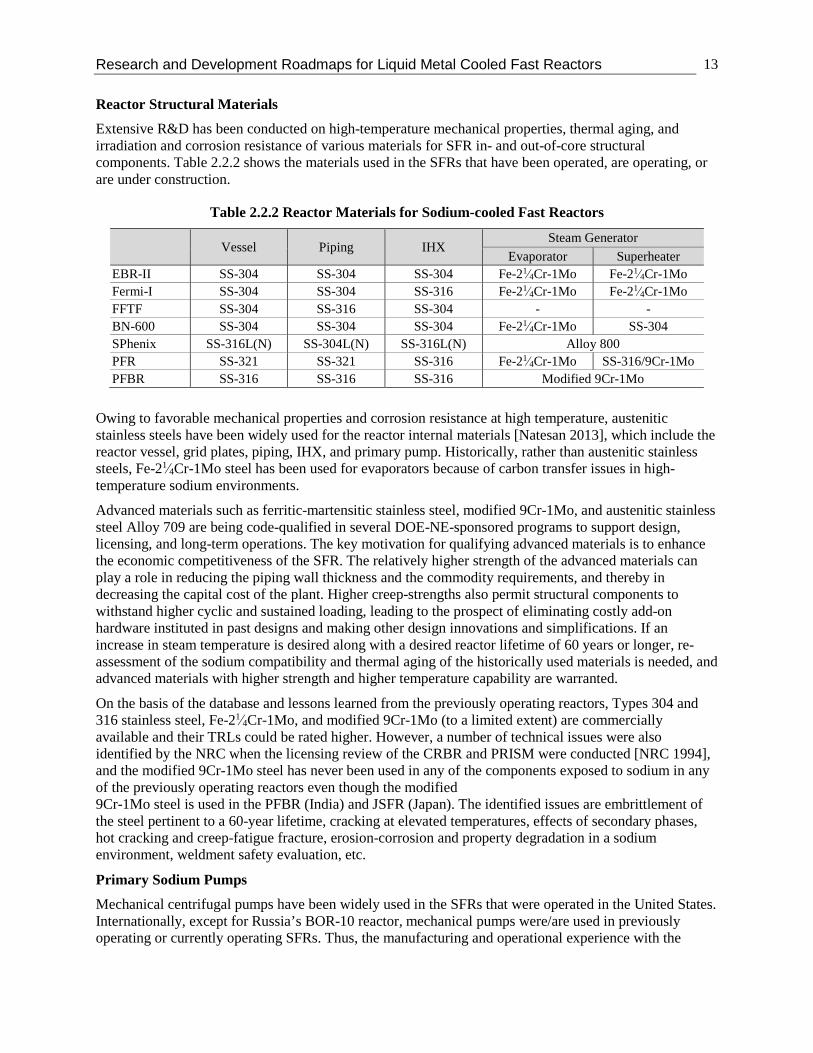
Extensive R&D has been conducted on high-temperature mechanical properties, thermal aging, and irradiation and corrosion resistance of various materials for SFR in- and out-of-core structural components. Table 2.2.2 shows the materials used in the SFRs that have been operated, are operating, or are under construction.
Table 2.2.2 Reactor Materials for Sodium-cooled Fast Reactors
Vessel Piping IHX Steam Generator
Evaporator Superheater EBR-II SS-304 SS-304 SS-304 Fe-21⁄4Cr-1Mo Fe-21⁄4Cr-1Mo Fermi-I SS-304 SS-304 SS-316 Fe-21⁄4Cr-1Mo Fe-21⁄4Cr-1Mo FFTF SS-304 SS-316 SS-304 - - BN-600 SS-304 SS-304 SS-304 Fe-21⁄4Cr-1Mo SS-304 SPhenix SS-316L(N) SS-304L(N) SS-316L(N) Alloy 800 PFR SS-321 SS-321 SS-316 Fe-21⁄4Cr-1Mo SS-316/9Cr-1Mo PFBR SS-316 SS-316 SS-316 Modified 9Cr-1Mo
Owing to favorable mechanical properties and corrosion resistance at high temperature, austenitic stainless steels have been widely used for the reactor internal materials [Natesan 2013], which include the reactor vessel, grid plates, piping, IHX, and primary pump. Historically, rather than austenitic stainless steels, Fe-21⁄4Cr-1Mo steel has been used for evaporators because of carbon transfer issues in high-temperature sodium environments.
Advanced materials such as ferritic-martensitic stainless steel, modified 9Cr-1Mo, and austenitic stainless steel Alloy 709 are being code-qualified in several DOE-NE-sponsored programs to support design, licensing, and long-term operations. The key motivation for qualifying advanced materials is to enhance the economic competitiveness of the SFR. The relatively higher strength of the advanced materials can play a role in reducing the piping wall thickness and the commodity requirements, and thereby in decreasing the capital cost of the plant. Higher creep-strengths also permit structural components to withstand higher cyclic and sustained loading, leading to the prospect of eliminating costly add-on hardware instituted in past designs and making other design innovations and simplifications. If an increase in steam temperature is desired along with a desired reactor lifetime of 60 years or longer, re-assessment of the sodium compatibility and thermal aging of the historically used materials is needed, and advanced materials with higher strength and higher temperature capability are warranted. On the basis of the database and lessons learned from the previously operating reactors, Types 304 and 316 stainless steel, Fe-21⁄4Cr-1Mo, and modified 9Cr-1Mo (to a limited extent) are commercially available and their TRLs could be rated higher. However, a number of technical issues were also identified by the NRC when the licensing review of the CRBR and PRISM were conducted [NRC 1994], and the modified 9Cr-1Mo steel has never been used in any of the components exposed to sodium in any of the previously operating reactors even though the modified 9Cr-1Mo steel is used in the PFBR (India) and JSFR (Japan). The identified issues are embrittlement of the steel pertinent to a 60-year lifetime, cracking at elevated temperatures, effects of secondary phases, hot cracking and creep-fatigue fracture, erosion-corrosion and property degradation in a sodium environment, weldment safety evaluation, etc.
Primary Sodium Pumps
Mechanical centrifugal pumps have been widely used in the SFRs that were operated in the United States. Internationally, except for Russia’s BOR-10 reactor, mechanical pumps were/are used in previously operating or currently operating SFRs. Thus, the manufacturing and operational experience with the

Research and Development Roadmaps for Liquid Metal Cooled Fast Reactors
14
mechanical pumps should be sufficient for commercial demonstration, although testing of the pump would be important. In the United States, the operational experience was limited to a mechanical pump for a small pool-type SFR (the 62.5-MWt EBR-II) and a relative large mechanical pump that had been built for the loop-type FFTF and CRBR.
Owing to the recognized benefits of the EM pump, which include ease of maintenance, lower cost, and longer insulator lifetime, some advanced SFR concepts have proposed using an EM pump for primary sodium flow. A submersible EM pump has been tested at full scale [GEH 2016] and developed for a 4S reactor by Toshiba [Aizawa 2010], but none have been used in the previously operating SFRs in the United States. Internationally, the BOR-10 (Russia) has used the EM pump. The manufacturing and operational experience is limited and additional R&D is needed for endurance testing and radiation-hardened insulation/shielding development.
Intermediate Heat Exchanger
The operational experience in EBR-II and FFTF, and extensive analysis, design, laboratory testing, and in-pile operations, have shown that shell-and-tube, counter-current flow heat exchangers function very reliably as intermediate heat transfer devices for SFRs so long as care is taken in designing the heat exchanger for sodium applications. Austenitic stainless steels were used for IHXs in the EBR-II, Fermi-I and FFTF.
The IHX occupies a substantial amount of space within the reactor vessel for pool-type plants, and similarly, a substantial amount of floor space on the reactor deck for loop-type plants. Thus, R&D efforts that focus on minimizing the size of these units with advanced materials are underway. One example is the use of advanced high-chrome ferritic steels that minimizes the heat transfer area required to transfer heat from the primary coolant to the steam generator. In addition, the use of kidney-shaped IHXs was proposed in the PRISM; also suggested was the use of twisted-tube IHXs to minimize the size of the IHX and its impact upon the reactor vessel size. These innovative IHX concepts have not been demonstrated in prototype or test reactors, and the cost reduction impact in future SFRs may be substantial.
For more advanced sodium cooled systems, the use of a supercritical CO2 (SCO2) turbine-based power conversion system is being considered. It would be significantly more efficient to use a compact heat exchanger (CHE) to couple the sodium to the SCO2. Examples of CHEs currently in widespread use in the fossil and petrochemical industry include printed circuit heat exchanger and plate-fin designs that may be appropriate for nuclear applications, but there are no design or inspections rules approved by ASME for such CHEs for nuclear systems at this time. DOE-NE is currently funding R&D to develop both the technology for such nuclear-grade CHE’s and the development of their Code design and inspection rules.
Decay Heat Removal System
Various decay heat removal systems have been used in previously operating SFRs and those that are under development; these include DRACS, SGACS, RVACS, IRACS, Primary System Auxiliary Cooling System (PSACS), etc. The operational experience in the EBR-II and in-pile and out-of-pile testing and analysis show that the decay heat removal systems readily maintain temperatures below design limits under both steady-state and transient natural convection flow conditions when the system is designed with flow paths that allow natural convection to develop.
Power Conversion System
The Rankine/steam cycle is a popular power conversion system in various nuclear plants, including the SFRs which operated in the United States in the past and commercially operating Light Water Reactors (LWRs). The steam generator technology for the SFR is similar to the technologies adopted in LWRs, except that SFRs have higher temperature and higher pressure on the steam side and higher temperature and lower pressure on the sodium side, and materials of construction must be compatible with both the sodium and water environments. Owing to the potential for sodium-steam interaction, a double-walled

Research and Development Roadmaps for Liquid Metal Cooled Fast Reactors
15
tube steam generator was used in the EBR-II (actually, two different types were used), but further study is needed to access the applicability of this technology to larger reactors. The reliability of the steam generator is an important factor when determining the overall plant performance as the failure of a single steam generator tube will cause a sodium-water reaction (if not caught early) and thereby requiring accident management and reactor shutdown. In order to improve the reliability and save capital cost, advanced materials such as high-chrome ferritic steel have been proposed for use in the steam generator.
The SCO2 Brayton cycle is under development as an advanced power conversion system. The key motivations for using the SCO2 Brayton cycle include elimination of the potential sodium-water reactions and substantial savings on capital costs from remarkably small turbomachinery and potentially higher thermal efficiency. However, extensive R&D is required to demonstrate the SCO2 Brayton cycle in a high-temperature sodium environment representative of an interface with an SFR, including studies of material compatibility, reactions between carbon dioxide and sodium, and CO2 effects on turbomachinery and sealing materials.
Other Systems (Instrumentation and Control, In-Service Inspection, Maintenance, Monitoring, and Balance of Plant)
Through the previously operating SFRs, the technologies for the I&C system, In-Service Inspection (ISI) system, reactor maintenance monitoring system, and balance-of-plant (BOP) were developed and operational experience was accumulated. For instance, failed-fuel detection technologies based on gamma spectroscopy and the fission tag gas technique were developed at EBR-II and applied to FFTF [McCormick 1974]; there have been significant technological advances over the last 20 years in robotics and imaging systems for sensor packaging (actuators, sensors, and miniaturization); and generally, BOP technologies are similar to the technologies adopted in LWRs, except that the systems run at a higher temperature.
Reactor Licensing
As DOE facilities, EBR-II and FFTF did not receive a license from the NRC. However, FFTF had undergone a full-scale regulatory review to make sure it adhered to the strictest independent regulatory review process [FFTF 1997], and to bring the NRC up to speed for licensing SFRs. Fermi-I received a license from the Atomic Energy Commission before the NRC was established. Historically, the NRC has conducted pre-construction reviews for CRBR and pre-application reviews for SAFR and PRISM, but the licensing reviews were pending or terminated before a final decision was made. The PSAR for the CRBR was prepared for licensing review, but the CRBR program was canceled in 1983, days before the NRC was planning to issue the CRBR project a construction license. The NRC conducted pre-application activities and provided feedback in the form of Pre-Application Safety Evaluation Reports for SAFR in 1991 [NRC 1991] and for the PRISM/Mod-A in 1994 [NRC 1994]. Except for these activities, there was a limited submission for licensing review. Recently, anticipating potential licensing applications, the NRC unveiled its vision and strategy for non-LWR review [NRC 2016], and there were DOE-NRC joint activities and workshops for developing licensing requirements [INL 2014]. Moreover, the GIF recommended consolidating safety design criteria and validating/qualifying the computer codes that are related to the SFR licensing review [GIF 2014].
2.3 Concept Description of Lead-cooled Fast Reactor Research and development efforts on heavy liquid metal (lead or lead-bismuth eutectic [LBE])-cooled fast reactors was initiated in the 1950s in the Soviet Union (Russia) strictly for military purposes, i.e., for submarines propulsion. Owing to its lower melting temperature, LBE was preferred over pure lead. Eight nuclear submarines, of which one was powered by two 73-MWt LBE-cooled reactors and seven were powered by a 155-MWt LBE-cooled reactor [Cinotti 2010], were operated in the Soviet Union and the Russian Federation, providing 40 years of reactor operational experience; together with 70- and 155-MWt land prototypes, a total of approximately 80 years of reactor operational experience has been gained. The

Research and Development Roadmaps for Liquid Metal Cooled Fast Reactors
16
Russians did first construct and operate a smaller-scale demonstration of a LBE-cooled reactor (e.g., a technology pilot plant) to demonstrate and prove the technology, owing to the military urgency of deployment. The submarine reactors were pressed into service and filled the role of test reactors as well as operational systems. Technical difficulties and accidents occurred during reactor operation, and lessons were learned as experience was gained in LBE coolant technology, material corrosion performance, mass-transfer in LBE systems, and polonium-210 handling. Limited descriptions of the reactors and accidents have been presented in the open literature. Also, because of its sensitive nature as technology applied to military use, detailed design information on the LBE-cooled submarine reactors has never been provided. Three notable accidents [Zrodnikov 2000] included a core partial meltdown in 1968 in one of the two reactors of the first reactor-equipped submarine, resulting from the early lack of experience with LBE coolant; the corrosion cracking of coolant pipelines in 1971; and the global corrosion damage of a steam generator (S/G) in 1982. The latter two accidents were unrelated to the use of LBE coolant or a fast neutron spectrum.
Even though reactor operational experience with heavy liquid metals has been gained so far with LBE coolant only, a large fraction of the civil reactor development projects over the past 15 years have focused on pure lead as a coolant. The reason for this is to be found in some unfavorable features perceived by some designers for LBE vs. pure lead [Smith 2016]. The most relevant is the production of highly radioactive polonium-210 (a 5.3-MeV alpha emitter with a half-life of about 138 days) from the neutron capture reaction by bismuth [Tarantino 2012]. This isotope, in addition to being a hazard in case of leakage, constrains access, inspection and maintenance of reactor components and represents a non-negligible heat load that would add to the decay heat normally generated by the fuel. It is noted that the pure lead is not exempt from generation of polonium-210, but the rate of polonium-210 generation rate in the pure lead is approximately four orders of magnitude lower than in LBE. Another drawback of LBE is the low bismuth content in the Earth’s crust, which is perceived to be insufficient to support a large commercial fleet of LBE-cooled fast reactors. Consistent with this approach, the coolant selected by the Generation IV International Forum is pure lead rather than LBE.
The R&D efforts on LFR technologies in the United States have been relatively limited as the domestic fast reactor program has been historically focused on SFR technologies. This was mainly because of the more corrosive nature of lead and LBE vs. sodium, and because of the significantly shorter fissile doubling time in the SFRs compared to LFRs as a result of higher power density, which was an important reactor performance characteristics when the U.S. fast program stated [Loewen 2003]. Recently, however, several LFR designs began development in the United States, owing to some advantages as an alternate fast reactor option [Sakamoto 2013].
Unlike sodium, the lead and lead alloys are relatively inert and do not chemically react with water and air. This may allow for some simplification of the reactor safety systems. This has favorable implications on safety and allows for some simplification of the reactor safety systems. Moreover, the very high boiling point of lead (~1740°C) results in a significant margin to coolant boiling, potentially allowing for an increase in plant’s thermal efficiency through operation at temperatures (above 550°C and up to 750°C) higher than those at which structural materials have been demonstrated so far (~500°C). This however requires the development and/or demonstration of adequate corrosion-resistant cladding and structural materials, which is being pursued in recent years both domestically and internationally [Short, 2012, 2013], [Ejenstam 2015], [Garcia Ferre 2013, 2015]. In addition, lead alloys behave as a superior neutron reflector, which improves the neutron economy and reduces the coolant void worth. The combination of low void worth and high boiling temperature should improve safety margins for loss of flow events, as compared to conventional SFR designs. The development of LFRs in the United States includes the 125-MWt (50-MWe) Encapsulated Nuclear Heat Source under development by the University of California at Berkeley [Hong 2005]; the 75-MWt (25-MWe) Gen4Module (a.k.a. Hyperion) by Gen4 Energy; a series of Secure Transportable Autonomous lead-cooled fast Reactor (STAR) modules, such as SSTAR [Sienicki 2007], STAR-LM, SUPERSTAR

Research and Development Roadmaps for Liquid Metal Cooled Fast Reactors
17
[Sienicki 2011], and LakeChime-Evolutionary-STAR, by the DOE National Laboratories and industry; the 500-MWt (210-MWe) Demonstration Lead-cooled Fast Reactor (DLFR) developed by Westinghouse within the Advanced Demonstration and Test Reactor (ADTR) Study [Westinghouse 2016]; and the 450-MWt (200-MWe) LFR-AS-200 by Hydromine [Cinotti 2016].
Recognizing the same motivations, the European Atomic Energy Community (Euratom), Japan, South Korea, and the Russian Federation are interested in LFR development and are members of the LFR Provisional System Steering Committee of Generation IV International Forum (GIF), where the United States and China are participating as observers. Although there does not yet exist a GIF LFR Framework Agreement, Euratom, Japan, the Russian Federation, and South Korea have signed a Memorandum of Understanding (MOU), and China has recently started a large LFR program and is expected to sign the MOU soon.
The LFRs which have been developed internationally are the ~100-MWt accelerator-driven LBE-cooled fast reactor MYRRHA being developed by SCK.CEN (Belgium) [Jaluvka 2012, De Bruyn 2015]; the 1500-MWt (600-MWe) European Lead-cooled System (ELSY) and its evolutionary version of the European Lead Fast Reactor (ELFR) by Euratom [Alemberti 2011]; the 300-MWt (125-MWe) Advanced Lead-cooled Fast Reactor European Demonstrator by the FALCON consortium, formed by Ansaldo Nucleare (Italy), ENEA (Italy), the Nuclear Research Institute (Romania), and the Nuclear Research Institute Řež (Czech Republic); the 700-MWt (300-MWe) BREST-OD-300 by NIKIET (Russia); the 280-MWt (100-MWe) SVBR (the Russian acronym for lead-bismuth fast reactor) by AKME (Russia) [Antysheva 2011]; the 3- to 10-MWe Swedish Advanced Lead Fast Reactor by LeadCold (Sweden) [LeadCold 2017]; and the 10 MWt China Lead-based Reactor (CLEAR-I) for accelerator-driven system research by China [Wu 2016].
The ELFR, BREST-OD-300, and SSTAR were selected as the reference LFRs by the Generation IV LFR Provisional System Steering Committee, and their key design parameters are compared in Table 2.3.1, along with those of the design that Westinghouse developed within the ADTR study (DLFR).
Table 2.3.1 Comparison of Generation IV Reference LFRs and DLFR
Design parameter SSTAR ELFR (ELSY) BREST-OD-300 DLFR
Developer DOE National Laboratories EURATOM NIKIET (Russia) Westinghouse
Coolant Pb Pb Pb Pb Power, MWt/MWe 45/20 1500/600 700/300 500/210 Primary system type Pool Pool Pool Pool Fuel form Nitride a) Oxide Nitride Oxide b) Fuel composition (TRU)N (U,Pu)O2 (U,Pu)N UO2
Coolant outlet temp., oC 567 480 540 510 Power conversion SCO2 Brayton Steam Steam Steam Ave. driver burnup, GWd/t 81 < 100 5.5% 100
Cladding material Si-enhanced
ferritic/martensitic stainless steel
T91 (Fe-Al coated) Ferritic-martensitic
stainless steel D9 coated with Al2O3
Primary sodium pump Nat. circulation Mechanical Mechanical Mechanical a) Metal fuel is an alternative option. b) To be followed by an advanced fuel such as nitride or advanced metal fuel such as that discussed in [Waltars 2010].
All LFRs in Table 2.3.1 have adopted a pool-type primary configuration and ceramic fuels, and the coolant outlet temperature is in the range of 480–567oC, depending on the cladding materials and on the coating technology used. The SSTAR has proposed the use of a SCO2 Brayton cycle, while other LFRs have adopted a steam cycle. The deployment is planned in the mid-2020s to mid-2030s time frame, which

Research and Development Roadmaps for Liquid Metal Cooled Fast Reactors
18
seems an aggressive schedule compared to the TRLs of the LFR technologies. A long-term goal to further increase economic performance is to increase the coolant temperature to values higher than those permitted by currently proven materials, e.g., up to 750oC, which would drastically increase plant’s thermal efficiency.
2.4 Technology Maturity of Lead-cooled Fast Reactor LFRs have not been built or operated in the United States. The LFR technology gaps, which have been discussed in the Generation IV program context [Tarantino 2012, GIF 2002], are mainly related to ensure reliable operation of materials in high-temperature flowing lead and, when applicable, under neutron irradiation. It should be noted, however, that the readiness of the materials to be used for LFR components exposed to liquid lead is very dependent on the temperature at which such components are designed to operate. Because of this, the technology roadmap envisioned by some LFR developers, for example Westinghouse, consists of a more near-term prototype reactor operating at or below 550°C, followed by units whose operation at higher temperature will be conditional to the successful demonstration of materials at such temperatures.
There have been nearly 20 years of research on LBE and lead coolant corrosion control with over a dozen test loops in Europe, Japan, South Korea, and the United States [OCED 2015, Sakamoto 2013]. LFR corrosion, as well as Liquid Metal Embrittlement (LME), is now better understood and means to self-generate and maintain, or directly apply, a protective layer/coating against corrosion have been demonstrated at the laboratory-scale, but not with alloys approved for nuclear construction by the ASME Code. Moreover, it has been observed that austenitic steels such as SS-316 tend not to be susceptible to LME, unlike ferritic-martensitic steels such as T91, thereby making them preferred candidates for lead-cooled fast reactors by some designers, especially at temperatures below 500°C [Cinotti 2012].
Regardless of the corrosion protection strategy adopted, the oxygen content in the primary coolant must be controlled within specified limits. The upper limit, analogously with SFRs, is to avoid precipitation of oxides while the lower limit is to ensure an effective self-passivation of the components that are not protected from corrosion in some other way, such as through coatings. The challenge to ensure corrosion protection for the whole primary system, through oxygen control, is very dependent on the operating temperatures and on the corrosion protection strategy adopted. In fact, while the performance of an effective and robust oxygen control system for power reactor utilization must still be demonstrated at engineering scale over extended cycle lengths on alloys suitable for nuclear construction, oxygen control can be simplified significantly if, instead of relying on self-passivation of materials only (which necessitate of different oxygen concentrations depending on their temperature), coatings are instead applied to the primary system components operating at the highest temperatures (e.g. fuel rod cladding). This would in fact allow decoupling corrosion protection of the high- from the low-temperature components [Smith 2016], thereby permitting oxygen control to target protection of the latter only.
The interplay between temperature and oxygen control can be seen in Figure 2.4.1 which shows how the coolant inlet and outlet temperatures of the ELSY (ELFR) reactor concept were determined [Tarantino 2012]. The ELSY reactor concept adopted an austenitic stainless steel (AISI 316L) for the majority of the primary system components and the reactor vessel. Below approximately 500°C adequate oxygen control can ensure protection of these materials through self-passivation, with a required oxygen concentration that increases with the component’s operating temperature. However, if such temperature exceeds approximately 500°C, which is often the case for the fuel rod cladding, the oxide layer formed on austenitic steels is no longer protective and alternative measures must be taken for corrosion protection. Hence, the coolant inlet and outlet temperatures were determined such that the inlet (400°C) is higher than the lead melting temperature and the outlet (480°C) is lower than the corrosion design limit for oxygen control of austenitic steels, with some margin.
As shown in Figure 2.4.1, a technology gap exists when a conventional austenitic stainless steel is used for the fuel cladding as the peak temperature for this component is as high as 560oC. Coatings, alumina-

Research and Development Roadmaps for Liquid Metal Cooled Fast Reactors
19
forming austenitic steels and Functionally Graded Composites have been investigated in recent years to fill such gap, showing promising results [Garcia Ferre 2013, 2015], [Ejenstam 2015], [Short 2012].
It is important to note that use of coatings for safety related structures in nuclear reactors must be rigorously assessed to ensure the coatings provide adequate protection for the lifetime of the structure. It is critical they do not form non-protective openings allowing access to the underlying material, spall or otherwise separate from the structure causing debris in the coolant, and are not adversely affected by mass transport from either the coolant or the underlying substrate during the lifetime in which they must provide protection.
Questions about the efficacy of oxygen level control in the coolant for corrosion prevention in lead and lead-bismuth cooled reactors remain open. The window of oxygen concentration between which liquid metal embrittlement (LME) from significant alloy content dissolution into the coolant and oxidation of most structural alloys occurs is quite narrow. While it has been shown to be obtainable at laboratory scale, it must be demonstrated that this level of control can be obtained and maintained globally throughout the entire primary circuit for it to be effective in a reactor system.
Figure 2.4.1 Operating temperatures of ELFR
The high coolant density of lead alloys (roughly a factor of thirteen greater than sodium) requires special consideration as it challenges components mechanical design and practically constraints the size of the LFR, especially if seismic events are to be accommodated without the use of seismic isolators.
If no primary system design modifications were made relative to an SFR, simply replacing sodium with lead would result in a far from optimal LFR, with a very significant mass of lead and a high pumping power. This is because, in addition to the high density of lead, erosion/corrosion considerations tend to limit the coolant velocity in the core below 2-3 m/s (vs ~6 m/s for SFRs) which, in the heat balance across the core, cannot be entirely compensated by lead’s “only” 40% higher volumetric heat capacity relative to sodium [Smith 2016]. At low power density, natural circulation cooling can be exploited, possibly to
Research and Development Roadmaps for Liquid Metal Cooled Fast Reactors
20
eliminate the need for primary coolant pumps. Low power density also results in extended fuel lifetime to reach a fuel burnup limit; this is exploited in many LFR designs to limit fuel handling and on-site storage with associated proliferation advantages [Yang 2005]. On the other hand, low power density implies larger core volumes with associated economic penalties. Possible solutions being investigated to increase the LFR power density are the use of gas injection above the core to enhance the circulation rate without the use of costly mechanical pumps [Sienicki 2001].
Proper design of an LFR requires departing from typical SFR configurations, which is often facilitated by exploiting some of lead’s favorable properties. For example, lead’s excellent neutronic characteristics for fast spectrum applications combined with its good heat transfer properties allow to open the fuel lattice with a smaller penalty on neutron spectrum/flux than if the coolant was sodium. This helps to reduce core pressure drop, ultimately favoring removal of a significant fraction of power through natural circulation of primary coolant [Smith 2016]. Analogously, the high coolant density of lead alloys also enables axial flow mechanical pumps to be installed in the hot leg of a pool reactor configuration by virtue of the lower submerged height required for a net positive suction head [Cinotti 2007]. In spite of the generally lower core power density of LFRs relative to SFRs, if properly implemented these design modifications can result in a compact primary system and therefore in an increased primary system power density.
Regarding fuel forms, nitride or oxide fuel is preferred because of its compatibility with the lead coolant and, especially for nitride, high temperature potential which in an LFR would not be limited by coolant boiling concerns but rather by materials’ corrosion performance in high-temperature lead. A significant R&D program is however required for demonstration of the fabrication and irradiation performance of nitride fuels. Alternate designs with metal fuel are possible, although with lower temperature capabilities than nitride fuel; an attractive option is to use a metal fuel design that does not need for an internal sodium bond between the metal fuel slug and surrounding cladding, such that proposed in [Walters 2010]. The most significant challenges result from the corrosion and liquid-metal embrittlement (LME) of cladding and structural materials when in contact with the lead coolant at high temperature. This tendency, which is accelerated at higher temperatures, requires careful material selection and monitoring during plant operations. In addition, erosion of the structural materials in the high-temperature lead environment can increase as coolant velocity increases above a certain threshold. Thus, the major thermal-hydraulic design parameters of the LFR (for instance, coolant inlet and outlet temperatures and coolant velocity) are limited to avoid the corrosion, embrittlement, and erosion of the cladding and structural materials.
Since the heat transfer characteristics of the two liquid metals (lead and sodium) are similar, the LFR may leverage the favorable features and rationales associated with SFR passive safety features (the large margin to coolant boiling, large thermal inertia based on pool-type configuration, and favorable reactivity feedbacks with metallic or nitride fuel forms). However, a major effort is needed to actually demonstrate passive safety performance under both normal and transient conditions using lead as a coolant.
The TRLs of major reactor components of the LFR have been assessed [INL 2017], but those were also revisited and revised to accommodate the recommendations from industry experts and the progress achieved through domestic and international LFR programs. The current TRLs of key LFR components are summarized in Table 2.4.1.

Research and Development Roadmaps for Liquid Metal Cooled Fast Reactors
21
Table 2.4.1 TRLs for Engineering Demonstration of LFR by the Early 2030s
Key Component System TRL
Nuclear Heat Supply
Fuel Element 4 – 8 *) Reactor Internals 4 – 6 *) Reactivity Control 4 *) Reactor Enclosure (vessel, overhead, etc.) 6 *) Operations/Inspection/Maintenance 4 *) Core Instrumentation 4 *)
Heat Transport
Coolant Chemistry Control/Purification 5 *) Primary Heat Transport System 5 *) IHX a) n/a Pumps/Valves/Piping 4 *) Residual Heat Removal 5 *)
Power Conversion
Turbine 7 Steam Generator 6 *) Pumps/Valves/Piping 7
Balance of Plant
Fuel Handling & Interim Storage 5 *) I&C 6 Radioactive Waste Management 6
Safety Inherent (Passive) Safety Features 6 *) Active Safety System b) 4 *)
Licensing Safety Design Criteria and Regulations 3 Licensing Experience 1 *) Safety & Analysis Tools 4 *)
*) TRL were changed from the values assessed in Ref. [INL 2017] a) Lead’s compatibility with water allows considerations for the reactor design without
intermediate heat transport system. b) Active safety systems may or may not be needed in an LFR.

Research and Development Roadmaps for Liquid Metal Cooled Fast Reactors
22
3 R&D Needs 3.1 Common R&D Needs for Advanced Reactors In the advanced demonstration and test reactor options study [INL 2017], key subsystems that must be matured for demonstrations are summarized. Any roadmap must include the impact of development on those subsystems that are on the reactor’s critical paths to near-term deployment. Other systems and subsystems must be developed and/or adopted in order to provide nominal operational readiness and longer-term performance goals. Several advanced reactor concepts may possess common systems and subsystems. Items common to multiple systems include the following:
- Advanced materials and high temperature design methods for reactor structures, piping, heat exchangers, and power conversion system (SFR, LFR)
- Refueling systems (SFR, LFR) - System and components that contribute to inherent safety (all advanced reactors) - Auxiliary systems (all advanced reactors) - Reactivity (SFR, LFR) - Seismic isolation (all advanced reactors) - SCO2 power conversion system (SFR, LFR) - ISI system in high-temperature liquid metal environment (SFR, LFR) - Decay heat removal technology through reactor vessel auxiliary cooling system (SFR, LFR,
HTGR) - Advanced reactor licensing requirements and frameworks (SFR, LFR) - Advanced modeling and simulation capability (all advanced reactors)
The NRC has not endorsed the design rules in the ASME Boiler and Pressure Vessel Code, Section III, Division 5, for advanced reactors. R&D support to develop an ASME roadmap and to address any recommended actions in assisting the endorsement of Division 5 by the NRC is a common need for all six advanced reactor concepts identified by DOE.
3.2 Sodium-cooled Reactor R&D Needs DOE’s liquid metal-cooled fast reactor program was conducted for decades and produced the system and technologies that went into FERMI-I, EBR-II, FFTF, CRBR, and the reactor concepts for the ALMR program. In addition, the Liquid Metal Fast Breeder Reactor (LMFBR) program contained programs on large-component technology development for the commercial plant that would be built after the CRBR, called LDP/LSPB.
Table 3.2.1 shows the technologies that will potentially be implemented in commercial demonstration reactors by the early 2030s and in commercial reactors by 2050. Because there is about a 20-year time-lag, TRL implementations for the demonstration and commercial reactors are different. One of the critical requirements to meet DOE’s demonstration goal is to complete construction by the early 2030s, which requires high-TRL technologies and qualification of fuels and materials. However, the commercial reactors may employ advanced technologies (even though TRLs are currently low) to enhance reactor performance characteristics substantially.

Research and Development Roadmaps for Liquid Metal Cooled Fast Reactors
23
Table 3.2.1 SFR Technologies for Demonstration by Early 2030s and Commercialization by 2050
Demonstration by the Early 2030s Commercialization by 2050
Objective - Commercial demonstration reactor - High-performing commercial reactor based on closed fuel cycle
Fuel - U-Zr (or U-Pu-Zr) - HT-9 cladding
- U-TRU-Zr - Advanced cladding - High burnup based on fission products
vented fuel
Reactor structural materials
- Use of existing ASME code-qualified austenitic stainless steels for 60-year lifetime components and low-chrome ferritic steel for replaceable steam generator design
- Advanced ferritic-martensitic stainless steel (modified 9Cr-1Mo) and advanced austenitic stainless steel (Alloy 709)
Primary pump
- Mechanical centrifugal pump (submersible self-cooled EM pump is potential alternative if further developed)
- Mechanical centrifugal pump or submersible EM pump
In-vessel Refueling System
- Dual plug system with straight pull and/or fixed arm
- Single rotatable plug system with pantograph in-vessel transfer machine
- Dual plug system with straight pull and/or fixed arm
- Single rotatable plug system with pantograph IVTM
Reactivity Control System
- Primary – segmented-arm control rod drive mechanism (CRDM) with gripper
- Secondary – Drive motors with gravity insertion and fast drive in
- 2030 technology with possibility of EM latch developed for 2050
Core Restraint System
- Engineered limited free bow core restraint design
- Engineered limited free bow core restraint design
Power Conversion - Rankine/steam cycle - Rankine/steam cycle or SCO2 Brayton
cycle
Steam generator - Separate evaporator and super-heater - Once-through design
- Once-through design of sodium-to-CO2 heat exchanger
I&C
- Analog-digital hybrid plant control system (PCS) and protection system or all-digital PCS and protection system depending on NRC approval
- Single sensor alarms
- Cyber security - Supervisory control system - System-level automated data
reconciliation
In-service inspection
- Under-sodium viewing (USV) system for in-vessel viewing at refueling temperature
- Inspection robot for reactor vessel and guard vessel
- USV system for on-line monitoring that can operate at reactor core outlet temperature
- Automated inspection technology for reactor vessel and guard vessel
- Under-sodium repair technology for fast reactor applications
Safety
- Active safety systems and inherent safety features with goal of demonstrating to the regulator (NRC) inherent safety as designed into the commercial demonstration plant
- Credit for inherent safety based on periodic measurement of feedbacks during normal operation of commercial demonstration plant(s) with simultaneous updating of plant

Research and Development Roadmaps for Liquid Metal Cooled Fast Reactors
24
Demonstration by the Early 2030s Commercialization by 2050 - Credit for inherent safety based on
previous reactor operational experience and calculations
Probabilistic Risk Assessment (PRA)
Licensing - Two-step licensing based on 10CFR Part 50
- Either two-step licensing based on 10CFR Part 50 or one-step licensing based on 10CFR Part 52
Fuel cycle - Once-through fuel cycle - Full closed fuel cycle
Table 3.2.2 shows the notional schedule for design, licensing, and construction for commercial demonstration from 2017 to the mid-2030s, which was developed by assuming a two-step licensing process based on 10CFR Part 50: 1) construction permit (CP) based on the PSAR and the environmental review document, and 2) operation license (OL) based on the final design report during the reactor construction. The Advanced Demonstration and Test Reactor Options (ADTR) study [INL 2017] estimated that it would take about 13–15 years to complete the commercial demonstration, which includes the technology development, reactor designs, licensing reviews, and construction for the reactors evaluated during the ADTR study.
Table 3.2.2 Notional Schedule for Commercial Demonstration of SFR
Critical Path Timeline
17 20 25 30 35 Design Conceptual Prelim. Final Licensing Pre-review 1st for CP 2nd for OL Construction Procurement and Const.
The critical paths for commercial demonstration of the SFR by the 2030s, based on the notional schedule, are identified below and the timelines are linked in Table 3.2.3. It is currently premature to determine which parts of the reactor design and development will be led by a commercial vendor and which will be led or supported by DOE National Laboratories. The color codes are provided below Table 3.2.3.
• Reactor designs and licensing reviews (by vendor and NRC) - Conduct conceptual design by 2020 and submit Preliminary Safety Information
Document (PSID) for pre-review. - Conduct preliminary design by 2023 and submit PSAR and environmental review
documents for CP. - Conduct final design by 2026 and submit Final Safety Analysis Report (FSAR) for OL
and core loading permit. - Complete licensing review by the early 2030s.
• Fuels - Reserve fissile stockpile for startup core loading and complete qualification of U-Zr fuel
with HT-9 cladding using the legacy data before fabrication starts (mid-2020s). - Fabricate fuels before startup core loading (2030). - Continue the development of advanced fuels for future commercial reactors.

Research and Development Roadmaps for Liquid Metal Cooled Fast Reactors
25
Table 3.2.3 Notional Schedule for Commercial Demonstration of SFR by the Early 2030s
Critical paths Time line 17 20 25 30 35
Design (by vendor) Conceptual Prelim. Final Licensing review (by NRC) Pre-review 1st for CP 2nd for OL Construction (by vender) Procurement and construction Fuel Qualify U-Zr fuel Reserve fissile stockpiles and fabricate startup fuel Develop advanced fuel Reactor structural materials Help NRC to endorse ASME Division 5 code rules Extend austenitic SS design lives based on existing DB Develop flaw evaluation methods for austenitic SS Qualify advanced materials (Mod 9Cr-1Mo, A709) Computation codes for M&S Document legacy data for licensing review V&V of M&S codes (neutronics, T/H, safety, etc.) Fuel transient tests and validation of tools High fidelity analysis Component testing Sodium pumps, IHX, and steam generator Decay heat removal systems Fuel handling machine Reactivity control system Purification and sensor technologies Licensing framework Develop licensing requirements Resolve issues identified in previous reviews Others SCO2 power conversion USV system Flux monitoring system Sodium leak detection system
Design/Licensing/Construction Cross cutting (applicable to SFR) SFR specific R&D

Research and Development Roadmaps for Liquid Metal Cooled Fast Reactors
26
• Reactor structural materials - Support NRC endorsement of ASME Boiler and Pressure Vessel Code, Section III,
Division 5 (mid-2020s). - Extend ASME code allowables and design parameters to support 60-year design life for
304 and 316 stainless steels and associated weldments based on existing databases (early 2020s).
- Assess existing databases to extend service lives of non-replaceable stainless steel components in sodium and irradiation environment to 60 years (early 2020s).
- Resolve relevant structural integrity issues for 304 and 316 stainless steels and Fe-21⁄4Cr-1Mo and associated weldments that were identified by the NRC from the licensing reviews of the CRBR and PRISM [NRC 1994] (early 2020s).
- Develop high-temperature flaw evaluation methods to support long-term operations (mid-2020s).
- Continue the development and qualification of advanced materials (modified 9Cr-1Mo and Alloy 709) to enhance the economic competitiveness of the future commercial SFRs through a substantial reduction in commodity use, a simplification of the structural designs, and an improvement of thermal efficiency (early 2030s).
• Computation codes for modeling and simulations (M&S) - Document legacy data to support licensing review before detailed design (2021). - Perform verification and validation (V&V) of design and analysis tools that are used in
reactor final design (2023). - Resolve challenging design issues using high-fidelity tools in final design stage (2026). - Conduct fuel transient tests for development and validation of fuel transient analysis
codes. • Reactor components
- Perform component testing to ensure the functionality of major reactor components (control rod drive systems, primary pumps, IHXs, secondary pumps, purification system and components, steam generators, fuel handling system, etc.) before procurement (2025).
- Continue the demonstration of refueling technology for future commercial reactors. - Continue the demonstration or test of decay heat removal systems for future commercial
reactors. - Demonstrate I&C and ISI systems (USV system, flux monitoring system, sodium leak
detection system) before procurement (2025). • Licensing framework
- Develop licensing requirements and resolve issues identified in previous reviews prior to final design (2025).
• Knowledge preservation - Continue DOE’s fast reactor knowledge preservation activities under the ART program
to establish solid information for fast reactor systems and components. - Organize the information to support reactor vendor design efforts, licensing efforts, and
reactor analysis code validation.
Reactor design and development of documents for licensing review
Vendors will lead the demonstration reactor design and development of documents for licensing review, and the DOE will support these activities by providing required technologies and information. In order to meet the schedules by the early 2030s, vendors should develop multiple design documents, which include the PSID for pre-review, the PSAR for the CP, and the FSAR for the OL and the core loading permit. In addition, the environment review document for the reactor site is required for the CP. Thus, the potential reactor site should be identified when developing the PSAR.

Research and Development Roadmaps for Liquid Metal Cooled Fast Reactors
27
Most activities related to reactor design belong to the vendors and no major DOE R&D is expected.
Fuel elements (fuel and cladding)
Owing to its high technology maturity, the commercial demonstration SFR will use U-Zr binary fuel with HT-9 cladding and duct, which has been qualified in the previously operating SFRs in the United States, for the initial start-up core. However, depending on the progress in advanced fuel development and associated fuel cycle technologies, the U-Zr fuel will be followed by U-Pu-Zr ternary fuel or advanced metal fuels bearing Minor Actinides (MAs) to support a closed fuel cycle, which was recognized as the most promising fuel cycle by the Fuel Cycle Options Campaign [Wigeland 2014]. For substantial improvement of the reactor performance, the advanced fuel could reflect revolutionary concepts such as alternative alloys systems, sodium-free annular fuels, and fuels with minor alloy additions to immobilize fission products known to contribute to fuel-cladding chemical interaction, and advanced steels both with and without coatings/liners.
The FRTWG recommended expanding and commercializing fuel fabrication facilities to enable faster and cheaper fabrication of the metal fuels, and to manage the legacy fuel irradiation data from the EBR-II and FFTF for fuel qualifications.
The R&D needs for the fuels to be used in the demonstration SFR by the early 2030s are as follows:
- Document legacy irradiation fuel data and complete qualification of U-Zr fuel with HT-9 cladding and duct for licensing review;
- Reserve uranium fissile stockpile (enrichment higher than 5%) for the start-up core load; and - Demonstrate industrial-scale U-Zr fuel fabrication.
The R&D needs for the development of advanced fuels, which are needed for sequential commercial reactors by 2050, are as follows:
- Develop advanced fabrication processes targeting minimum losses of actinides while enabling economical industrial-scale deployment, which may involve remote operation;
- Characterize advanced fresh fuels and cladding; - Perform irradiation testing of advanced TRU-bearing fuels at steady and transient states; - Develop post-irradiation examination capability; - Conduct out-of-pile testing; and - Assess performance using high-fidelity M&S tools (e.g., BISON).
To support the R&D needs, testing and analysis capabilities are needed. These include irradiation tests at steady state and transient state; out-of-pile and furnace tests; in situ measurements and control; advanced characterization and Post-Irradiation Examination (PIE) techniques; and predictive M&S methods.
Reactor structural materials
On the basis of the experience with the previously operating SFRs and the accumulated irradiation, sodium compatibility, and mechanical properties databases from extensive R&D, the Type 304 and 316 austenitic stainless steels can be used, with some additional R&D efforts on ASME code rule extension, as the reference materials for structural components such as internals, enclosures, supports, IHX, and primary and secondary piping, with a full 60-year design life, to support the commercial demonstration by the early 2030s. The low-chrome ferritic steel Fe-21⁄4Cr-1Mo has a less comprehensive sodium compatibility database and would be suitable for a replaceable steam generator design with a maximum nominal service life of 36 years for the demonstration reactor.
R&D needs for the reactor structural materials for commercial demonstration by the early 2030s are as follows:
- Support the development of an ASME roadmap and address any recommended actions to assist the endorsement of design rules in the ASME Boiler and Pressure Vessel Code, Section

Research and Development Roadmaps for Liquid Metal Cooled Fast Reactors
28
III, Division 5, by NRC (this is a cross-cutting effort for all six advanced reactor concepts identified by DOE);
- Extend ASME code allowables and design parameters to support a 60-year design life for 304 and 316 stainless steels and associated weldments, based on existing databases;
- Assess existing databases to extend service lives of non-replaceable stainless steel components in sodium and irradiation environments to 60 years;
- Develop high-temperature flaw evaluation methods to support long-term operations; and - Resolve relevant structural integrity issues for 304 and 316 stainless steels and Fe-21⁄4Cr-1Mo
and associated weldments that were identified by the NRC from the licensing reviews of CRBR and PRISM [NRC 1994].
The advanced austenitic stainless steel Alloy 709 has been under development for a number of years and is currently being code-qualified as a replacement material for the 300-series austenitic stainless steels. Alloy 709 is also being considered as a construction material for a compact heat exchanger that couples the SFR with a SCO2 Brayton cycle, instead of a steam generator, as an option for the energy conversion system. The advanced ferritic-martensitic stainless steel modified 9Cr-1Mo has a significant strength advantage over the low-chrome ferritic steel Fe-21⁄4Cr-1Mo and can be used, with some additional R&D, as a construction material for a 60-year, non-replaceable steam generator design, and it can also be considered as a candidate material for an IHX design with a full 60-year design life. The key motivation related to the advanced structural materials is to enhance the economic competitiveness of the SFRs by reducing commodity use substantially, simplifying the designs, and improving thermal efficiency. These advantages will be realized in the sequential commercial reactors by 2050.
The R&D needs for the advanced materials are as follows
- Resolve relevant structural integrity issues that were identified by the NRC from the licensing reviews of CRBR and PRISM [NRC 1994];
- Extend ASME code allowables and design parameters for modified 9Cr-1Mo to support a 60-year design life based on existing databases;
- Expand or generate thermal aging, sodium compatibility, and irradiation databases and develop high-temperature flaw evaluation methods to support licensing and long-term operations;
- For early insertion of Alloy 709 into the structural design, generate data and develop ASME code cases for 100,000-, 300,000-, and 500,000-hour design lives as code qualification data become available;
- Fabricate and scale up Alloy 709 in different product forms to support reactor component construction; and
- Generate SCO2 compatibility data and implement recommendations from ongoing DOE’s Nuclear Energy University Program (NEUP) and Integrated Resource Program (IRP) projects on ASME design rules and nuclear code-stamping procedures for the design of a sodium-SCO2 compact heat exchanger.
To support the R&D activities for reactor materials, testing and analysis capabilities are needed, which include creep, fatigue, and creep-fatigue tests; material compatibility tests in a high-temperature sodium environment; material compatibility tests in a high-pressure CO2 environment for supporting SCO2 Brayton cycle power conversion; and irradiation tests of materials for the reactor internals. The mechanical properties test facilities and analysis capabilities of ANL, INL, and ORNL can be used to support ASME code case development, and the material compatibility tests in high-temperature sodium environments can be conducted by exposures in the small sodium loops and the Mechanisms Engineering Test Loop (METL) at ANL. The facility for long-term SCO2 compatibility testing will need to be established. A fast neutron source for generating irradiation data needs to be identified, although the projected displacements per atom (dpa) levels for core support structures, reactor vessel, IHXs, and primary piping are modest, so it is not in the critical path in terms of deployment schedule. Research

Research and Development Roadmaps for Liquid Metal Cooled Fast Reactors
29
results from NEUP and IRP projects on the use of ion irradiation as a surrogate for fast neutron irradiation will be leveraged to gain an early read on the irradiation resistance of these two advanced structural materials.
Reactor Inherent Safety
The technologies built upon the EBR-II platform (metal fuel, pool-type primary system, and passive decay heat removal systems) are mature enough to provide favorable inherent safety features to the demonstration reactor. Passive safety responses to unprotected transient events were demonstrated in the EBR-II in 1986 [Fistedis 1987], and the extensive analyses showed that the inherent safety features are mainly due to the large margin of sodium to boiling from operating temperature, sufficient thermal inertia in a pool-type system, and favorable reactivity feedbacks from metal fuels. In order to increase the reliability of the reactor safety performance, however, the passive safety responses to bounding events should be ensured [GIF 2002], and V&V of the M&S tools for reactor transient analysis are needed through experiments and tests performed in the previously operating SFRs in the United States and internationally.
Various decay heat removal systems (DRACS, RVACS, et al.) have been developed and proposed for SFRs and other advanced reactors. The operational experience in the EBR-II and in- and out-of-pile testing and analysis show that DRACS has the capability to maintain temperatures below design limits under both steady-state and transient natural convection flow conditions. For other systems, demonstration at full scale is needed to confirm their residual heat removal capability under normal operation conditions and emergency situations.
Metal fuel transient testing is needed in order to determine mechanisms that lead to metal fuel failure, failure threshold conditions, and the behavior of molten fuel under bounding conditions beyond the design basis. M-series metal fuel transient tests were conducted in the Transient Reactor Test (TREAT) facility between 1984 and 1987 [Bauer 1990] under overpower conditions, and the results were used to develop the transient analysis code SAS4A. The TREAT facility was shut down in 1994 without further transient tests. Recently, the DOE has decided to restart the TREAT facility by 2018, as also recommended by the FRTWG. After the TREAT facility is fully operational, additional transient tests are needed under various transient conditions (in particular, loss of flow).
Radial expansion reactivity feedback plays an important role in introducing negative reactivity to the core in an unprotected transient condition. However, since the reactivity feedback is dependent on the core restraint system, the negative reactivity insertion from the radial expansion should be demonstrated. Validation of the core-restraint design/analysis tools is also needed.
The R&D needs for reliable inherent safety performance are as follows:
- Verify the passive safety mechanisms during bounding events; - Carry out V&V of M&S tools for reactor transient analysis using data from experiments
performed in EBR-II, FFTF, and international facilities; - Restart TREAT and perform metal fuel transient tests; - Demonstrate the decay heat removal system at full scale; and - Demonstrate negative reactivity feedback from core deformation and validation of core
restraint system design tools.
Licensing
For the first-of-a-kind demonstration SFR, vendors will likely pursue a two-step licensing process based on 10CFR Part 50, which requires both a construction permit and a separate operating license. Recently, the NRC has developed implementation action plans [NRC 2016] aligning with the DOE, which include establishment of a more flexible, risk-informed and performance-based review process, development of licensing requirements and safety design criteria, data acquisition, and validation of licensing codes.

Research and Development Roadmaps for Liquid Metal Cooled Fast Reactors
30
On the basis of NRC’s risk-informed and performance-based regulatory structure of future plant licensing [NRC2007, NRC 2012], the probabilistic risk assessment (PRA) process would be an important component in the overall reactor design process. Limitations associated with advanced reactor PRA experiences are anticipated with the application of system modeling approaches and associated underlying hypotheses, to the risk metrics that are used, to failure data, and perhaps most importantly, to the design, materials, systems, and safety approach. Both advanced reactor license applicants and NRC staff will need to determine the technical adequacy of the PRA and know if it is sufficient to justify the specific results and risk insights used in support of a license application.
The NRC will lead the review and regulation of the SFR licensing, aligning with the DOE’s vision and goals. The DOE R&D needs are as follows:
- Support NRC in the establishment of a more flexible, risk-informed and performance-based review process (for instance, Probabilistic Risk Assessment);
- Support NRC in the development of licensing requirements; - Support NRC in acquiring/developing computer codes and validation; - Develop security measures and establish material control and accountability safeguard; and - Resolve technology issues that were identified in the previous licensing reviews (for instance,
evaluation of radiation source terms [Moe 2015]).
Computer code for modeling and simulations
Argonne Computation Code (ARC) systems have been widely used for fast reactor design and analysis. The legacy ARC system consists of the neutronics code suite (MC2-3/DIF3D/REBUS-3/PERSENT), fuel performance analysis code (LIFE-METAL), core deformation analysis code (NUBOW-3D/ANSYS), steady-state thermal-hydraulic analysis code (SE2-ANL), and reactor transient analysis code (SAS4A/SASYS-1). The neutronics code suite has recently been upgraded to solve neutron transport equations without diffusion approximations, which is compatible with the FRTWG’s recommendation, the improvement of deterministic methods based on the neutron transport equations for small fast reactor designs.
There are multiple ongoing activities to improve and validate legacy design and analysis tools; these activities include the NUBOW-3D/ANSYS code benchmark study under the bilateral Civil Nuclear Energy Research and Development Working Group with Japan, updating the metal fuel models of the SAS4A code as part of the PGSFR project with South Korea, validation of the SAS4A/SASYS-1 code through the IAEA/CRP FFTF transient benchmark, and validation of the LIFE-METAL code using irradiation data from EBR-II and FFTF as part of the PGSFR project. In addition, the high-fidelity multi-physics codes PROTEUS (neutronics), NEK-5000 (thermal-hydraulics and computational fluid dynamics), Diablo (system structure), and BISON (fuel performance) are under development in the Nuclear Energy Advanced Method and Simulation (NEAMS) program. Through NEUP projects, universities are improving the capabilities of both legacy and high-fidelity codes.
As a benefit of previous investments and the ongoing activities, the remaining R&D needs are mainly related to the validation and documentation of the design tools for licensing review. The FRTWG has recommended the revisiting of evaluated nuclear data for sensitivity-driving nuclides (e.g., U-238), and has asked to access the design tools.
The R&D needs in the computer code area are as follows:
- Document legacy tool information for licensing applications (manuals, validation data, etc.); - Carry out V&V of legacy and high-fidelity codes where gaps exit, using the experiments
performed in the domestic and international programs; - Resolve technically challenging issues (e.g., hot channel factors) using high-fidelity tools; - Perform Software Quality Assurance (SQA) on the computer codes; and - Quantify the uncertainties that are involved in the nuclear data and M&S.

Research and Development Roadmaps for Liquid Metal Cooled Fast Reactors
31
Reactor plant systems and components
As a result of the operational experience gained from EBR-II and FFTF and extensive studies in recent decades, no technical “show-stoppers” are anticipated in the reactor components if technologies that were developed in the 1950s for EBR-II and 1960s for FFTF are adopted by the vendors for their designs. However, most vendors are not adopting 1950s technologies for their reactor systems and components. The R&D needed for a vendor’s reactor plant systems and components will depend upon the needs of its plant design for commercialization; neither EBR-II nor FFTF were intended to be commercial demonstration plants. R&D needs will range from sub-component to full-component testing and from sub-scale to full-scale testing, depending upon the component. The remaining R&D needs are generally related to the enhancement of performance rather than a viability check. The R&D needs for each reactor component are as follows:
Fuel Handling System
For fuel transportation, loading, unloading, storage, and cleaning, the fuel handling system consists of the rotational plug, in-vessel fuel handling machine, ex-vessel fuel transportation device, in-vessel storage or/and ex-vessel interim storage, fuel cleaning station, etc. Even though there has been significant fuel handling experience at the previously operating fast reactors both domestically and internationally, each fuel handling system is tailor-made for the specific geometry of the plant and there is no standard design for fuel handling systems. Therefore, it is expected that some R&D will be beneficial in developing reliable and compact fuel handling systems for both the commercial demonstration reactor and the commercial reactor. It is expected that the ex-vessel systems will be very similar in both plants and the in-vessel components will be similar in functionality, but may be smaller for the demonstration reactor, depending upon the power level of both plants. To select a suitable fuel handling system, trade-off studies and component testing in a high-temperature sodium environment are recommended, including component function tests in the METL facility once it is operational.
In-Service Inspection, Maintenance, and Monitoring
In the EBR-II and FFTF, failed fuels were successfully detected by monitoring fission products/gases and delayed neutrons in the cover gas and primary coolant, using gamma and neutron spectroscopy techniques. The locations of the failed fuel subassemblies were identified using a fission gas tagging system. Given the remarkable progress that has occurred in gamma spectroscopy technology, the failed-fuel detection systems used in the previously operating SFRs along with modern spectroscopy techniques are expected to be adequate for the demonstration reactor.
Owing to the radiation and high-temperature environment, a remotely operated robotic vehicle with various sensors is employed to perform ISI of the reactor vessel and guard vessel. Significant technological advances have been made recently regarding fabrication of robotic systems and sensors. High-performance actuators, mechanisms, and sensors are now commercially available, and miniaturized components are also available for small robotic systems. It is expected that for the demonstration plant, an inspection vehicle will be developed, deployed, and demonstrated to function correctly. In addition, R&D will need to be conducted on how to adequately repair the reactor vessel or guard vessel if the inspection finds issues.
A USV system is expected to be deployed for performing ISI of systems and components inside a reactor vessel. Although these systems were developed while EBR-II and FFTF were operating, they were never deployed in either reactor. Various promising techniques,

Research and Development Roadmaps for Liquid Metal Cooled Fast Reactors
32
such as ultrasonic imaging, waveguide, and beam-forming systems, have been developed. In order to fulfill the ISI requirements, however, R&D is still needed to demonstrate sustained performance in a high-temperature sodium environment. The developed USV system can be tested in the ANL USV facility and/or in the METL facility (once operational).
Radiation monitoring systems are critical for protecting the plant workers and environment from potential radiation exposure. The radiation monitoring system used in LWRs is adequate for the demonstration SFR, and no R&D is anticipated.
Other sensors will be developed, such as level-sensing technology, oxygen detectors, hydrogen detectors, carbon detectors, etc.
In EBR-II, the fission products (mostly Cs), tritium, and corrosion products were controlled using the primary coolant cleanup system, which consisted of a cold trap and a nuclide trap. It is expected that the demonstration reactor will adopt coolant purification technology that was developed during the United States base technology development program. If so, then minimal technology development efforts will be needed. The PGSFR will adopt an almost identical technology to that used in EBR-II.
Primary Heat Transport System (Pumps/Piping)
Given the manufacturing and operational experience with mechanical pumps, they are expected to be mature enough for commercial demonstration; mechanical pumps have been used in most SFRs, although information on past mechanical pump technology will need to be recovered. In addition, the mechanical pump developed for the demonstration reactor plant will need to be tested (most likely in water) before insertion in the demonstration reactor plant.
Self-cooled EM pump technology has also been proposed for use in the primary heat transport system. A large-scale pump was developed by General Electric and Toshiba and was tested at the ETEC facility in California. It will be important to resurrect this work and continue R&D on this technology, such as endurance testing, redevelopment of high-temperature and radiation-hardened insulation materials, performance testing of these materials, and controls for the self-cooled EM pump.
Intermediate Heat Exchanger
On the basis of the operational experience in the EBR-II and FFTF and extensive analyses, the shell-and-tube, counter-current flow IHX with austenitic stainless steels is reliable and adequate for the demonstration SFR. However, R&D is needed to develop a more compact IHX by using higher-thermal-conductivity materials (for instance, 9Cr-1Mo steel or high-creep-strength materials such as Alloy 709) and alternative geometric configurations such as printed circuit or plate-fin compact heat exchangers and kidney-shaped IHXs.
Power Conversion System
The power conversion system based on the Rankine/steam cycle for the commercial demonstration reactor is similar to the technologies developed during the LMFBR large-component development program, such as the steam generator developed for the CRBR, the helical-coil steam generator, and the double-walled tube steam generator. With over 30 years of operational experience on the double-walled tube steam generator in EBR-II, strategies to avoid the sodium-water (steam) reaction are well understood. Further study is needed for the demonstration reactor, to ensure reliability of the steam generator

Research and Development Roadmaps for Liquid Metal Cooled Fast Reactors
33
system and to support reductions in cost by using advanced materials such as modified 9Cr-1Mo (high-chrome) ferritic-martensitic stainless steel.
An advanced power conversion system, the SCO2 Brayton cycle, is under development in support of two key objectives: elimination of the potential sodium-water reaction and higher thermal efficiency with the higher core outlet temperatures seen with LFR plants. However, as shown in Table 3.2.1, the application of the advanced power conversion system based on the SCO2 Brayton cycle is expected in 2050 timeframe with further R&D: for instance, demonstration of the SCO2 power conversion system in a high-temperature sodium environment at a large scale; material compatibility tests for materials such as Alloy 709 that have shown good compatibility with both sodium and SCO2; design, fabrication and nuclear code qualification development of a compact heat exchanger; and studies of the reaction between CO2 and sodium and of CO2 effects on turbomachinery and sealing materials.
Instrumentation and Control Systems
A neutron flux monitoring system is required to provide measurements that aid in reactor start-up and enable efficient plant control, to monitor reactivity changes, and to detect reactor abnormal conditions. The overall neutron flux varies by 12–14 orders of magnitude from reactor shutdown to full-power operation conditions. Flux monitoring in the high-temperature sodium environment is a challenging issue. A high-temperature fission chamber has been developed by ORNL, but R&D is needed to reconstitute the neutron flux monitoring system and test it in a high-temperature sodium environment. Testing of this instrument could be performed in the METL facility.
Various sensing technologies have been used in the EBR-II to monitor sodium leaks, and those technologies were planned for use in the CRBR. The collection of sensor design and test data from previously operating SFRs is needed, and performance tests are needed. In order to increase the level of reactor protection beyond that of previously operating SFRs, R&D is needed to develop a new sodium leak detection system, including the reconstitution of the technology used in the previously operating SFRs.
The existing PCS and plant protection system (PPS) based on hybrid analog and digital technologies, used in the previously operating SFRs and commercial LWRs, are adequate for the demonstration reactor. However, for future commercial reactors, R&D is needed to develop fully digital PCS and PPS technologies.
Facilities and Capabilities
To support the R&D activities targeting commercial demonstration by the early 2030s and commercialization by 2050, facilities and capabilities are needed for fuel fabrication, materials testing, component tests in a high-temperature sodium environment, and M&S.
• Fuel fabrication facility – The fuel for the startup core can be fabricated at INL, and in parallel, industry can supply the fuels for the subsequent reactors.
• Reactor material test – ANL, INL, and ORNL have creep test facilities, which will enable creep testing for 100,000 hours at 650oC per the ASME code cases.
• Reactor components test – Both material compatibility testing and component function testing in high-temperature sodium environments can be carried out at ANL in several small-loop facilities, and in the METL once it is operational.
• Fuel Transient Test Facilities - Restart of the TREAT facility is planned by 2018.

Research and Development Roadmaps for Liquid Metal Cooled Fast Reactors
34
• Irradiation capabilities – The United States does not have an operating fast neutron irradiation facility. The test fast reactor (or the demonstration reactor itself) can be utilized for fuel and material irradiation. According to the DOE vision and strategy statement, a potential new test reactor would be operational by the late 2020s if needed [DOE 2017].
• High-performance modeling and simulation – High-fidelity multi-physics tools may be needed to support the science-based development of advanced fuels, materials, and reactor concepts to understand their performance beyond the testing database.
• Advanced fuel characterization, PIE, and in-pile instrumentation – Advanced fuel characterization capability, PIE techniques, and in-pile instrumentation are essential to support the science-based fuel development program by providing phenomenological understanding of the materials and accurate data on the early restructuring behavior and response of the fuel system to steep power and temperature gradients.
• Fuel cycle facilities (separation and reprocessing) – For commercial reactors based on a closed fuel cycle, used-fuel separation and reprocessing facilities, remote fabrication of transmutation fuels, and safeguards approaches and equipment for the recycling facilities are needed. However, these fuel cycle facilities are not urgent for commercial demonstration of the SFR.
• Out-of-pile facilities – these are essential for developing the fuel performance codes for normal operations as well as accident conditions.
3.3 Lead-cooled Reactor R&D Needs Figure 3.3.1 shows the development and deployment pathways of various advanced reactor concepts [INL 2017]. For mature reactor concepts such as HTGR and SFR, it will take 13–15 years to advance from the current technology status to the commercial demonstration of the first module in the early 2030s. For a relatively less-mature reactor concept like FHR or LFR, it will take approximately 10–15 years to reach engineering demonstration and a number of additional years to reach commercial demonstration. It should be noted that this additional time needed to reach the commercial demonstration depends on the commercialization roadmap adopted by each developer, which could be shorter (< 10 years) by combining the engineering and performance demonstration, or longer (> 10 years) by separate engineering and performance demonstrates [INL 2017].
On the basis of the reactor development steps, the TRL assessment, and the leveraging of other SFR technologies, it is expected that the LFR technology will be at the engineering and performance demonstration stage by the early 2030s, and most activities from now to the late 2020s are focusing on the technology development to resolve design challenges and to demonstrate the viability of technologies in integral system. The R&D needs for engineering and performance demonstration of the LFR by the early 2030s are described in this section, and the timelines are linked in Table 3.3.1. Since it is expected that the commercial demonstration of a first LFR module will occur in the 2035–2040 timeframe, it was assumed that the preliminary design would start at the 2020s, after the preliminary reactor concept development stage.

Research and Development Roadmaps for Liquid Metal Cooled Fast Reactors
35
Engineering demonstration is for proof of concept, for concepts that have never been built. The goal of the demonstration at this level is the viability of the integrated system. Performance demonstration is to establish that scale-up of the system works and to gain operational experience to validate the integral behavior of the system, resulting in proof of performance.
Figure 3.3.1 Development and deployment pathways for different advanced reactors

Research and Development Roadmaps for Liquid Metal Cooled Fast Reactors
36
Table 3.3.1 Notional Schedule of Engineering Demonstration of LFR by the Early 2030s
Critical paths Time line
17 20 25 30 35 40 Design (by vendor) Prelim. Pre-concept. Conceptual Final Licensing review Pre-review 1st for CP 2nd for OL Construction Procurement and const. Fuel Qualify nitride fuel with reference cladding Develop/qualify advanced fuel w/ ref. cladding Develop/demonstrate advanced cladding materials Reactor structural materials Qualify reference structural materials Develop/demonstrate advanced structural materials Computational codes for M&S Update legacy tools for LFR design and analysis Validate LFR design codes Reactor components Coolant chemistry control technology Reactor coolant pump Decay heat removal systems Fuel handling system Seismic Licensing framework Update licensing requirements for LFR Others SCO2 power conversion Under lead viewing system Core monitoring system at high temperature in lead
Design/Licensing/
Construction Cross cutting (applicable to LFR) LFR specific R&D

Research and Development Roadmaps for Liquid Metal Cooled Fast Reactors
37
Reactor design and development of documents for licensing review
Vendors will lead the engineering demonstration reactor design and development of documents for licensing review targeting the operation in the 2035–2040 timeframe. By assuming the two-step licensing procedure based on the 10CFR Part 50, Vendors will develop multiple design documents, which include the PSID for pre-review, the PSAR for the CP, and the FSAR for the OL and the core loading permit. In addition, the environment review document for the reactor site is required for the CP. Thus, the potential reactor site should be identified when developing the PSAR.
Most activities related to reactor design belong to the vendors and no major DOE R&D is expected.
Fuel elements (fuel and fuel assembly materials)
As shown in Table 2.3.1, the most common fuel forms for the LFR are oxide and nitride, with advanced metal fuel also as a potential candidate especially for LFRs operating at relatively low temperature. Unlike oxide fuel, for which the irradiation database is adequate to predict fuel’s performance with confidence, information on the irradiation behavior (creep, swelling, etc.) of nitride fuel in a fast neutron environment is limited, thus requiring additional testing. Advanced metal fuel, on the other hand, could leverage some of the irradiation data and experience gained with conventional metal fuel, especially if the microstructure of this fuel, after limited irradiation to no more than 1-1.5 at%, can be demonstrated to be similar to that of typical metal fuel [Walters, 2010].
From the standpoint of irradiation behavior, the selection of the cladding material for LFRs can rely on the requirements and operational experience of SFRs. However, some critical requirements are related to the compatibility with lead coolant, particularly corrosion and liquid metal embrittlement. On this regard, the level of development and demonstration depends on the target temperature selected for this component, as an LFR can be designed to operate either at temperature levels for which corrosion resistance has been extensively tested (≤500°C) or at higher temperatures for which promising results have been obtained but further demonstration is needed. In the former conditions, 15/15Ti austenitic steels and double-stabilized austenitic steels, such as DS4, are promising candidates. Examples of candidate cladding materials at higher temperature conditions are certain alumina-forming steels, oxide dispersion-strengthened ferritic-martensitic stainless steel, Functionally Graded Composites and SiC composite, which however have a low TRL because of the limited irradiation experience and only preliminary corrosion testing under high-temperature LFR operation conditions.
Coatings on the cladding surface, such as Al2O3 through Pulsed Laser Deposition, can be an alternative solution to mitigate corrosion problems, especially in consideration of the excellent behavior demonstrated under irradiation, although with ions, up to 150 dpa [Garcia Ferre 2016]. However, it must be demonstrated that such a coating would be adherent to and protective for the clad or duct on which it applied. Otherwise, premature failure cannot be ruled out and issues related to debris from spalled or de-bonded coatings in the coolant would need to be addressed. Additionally, any changes to the composition of the coating and its resulting effectiveness due to species migration to or from the coolant or underlying substrate caused by thermal and/or irradiation-assisted diffusion would need to be addressed.
R&D needs for the fuel elements are as follows:
- Confirm corrosion resistance of the reference cladding materials selected for operation at or below 550°C under neutron irradiation, as to validate results obtained through ion irradiation;
- Develop and/or demonstrate advanced cladding materials that are corrosion-resistant in environments with high neutron flux and high-temperature lead (above 500-550°C, up to ~750°C);
- Perform irradiation testing of nitride fuels at steady and transient states; - Assess viability and irradiation performance of advanced metal fuel; and - Demonstrate fuel fabrication for both nitride and advanced metal fuels at industrial scale.
Research and Development Roadmaps for Liquid Metal Cooled Fast Reactors
38
To support the R&D needs, testing and analysis capabilities are needed. These include irradiation tests at steady state and transient state; in situ measurements and controls; advanced characterization and PIE techniques; and predictive M&S methods.
Reactor structural materials and coolant chemistry control
Corrosion (and LME when applicable) is the critical factors in selecting the structural materials for the reactor vessel and internals. Austenitic stainless steels and ferritic-martensitic stainless steels have been commonly considered as the structural materials for LFRs, with the former preferred by some designers as typical austenitic steels, such as SS316, have demonstrated not to be susceptible to LME [OECD 2015].
Experiments have confirmed that corrosion of the austenitic and ferritic-martensitic stainless steels strongly depends on the operating temperature and amount of dissolved oxygen in the lead coolant. As noted previously, the dissolved oxygen promotes the formation of oxide layers on the surface of metal structures, which acts as a barrier against corrosion by preventing leaching of alloying elements into the coolant. It has been demonstrated that generally, at temperatures below approximately 500°C and with a properly bounded dissolved oxygen activity, austenitic and suitable ferritic-martensitic stainless steels build up a stable protective oxide layer. However, at temperatures above 500-550°C, the formation and quality of the oxide layers are uncertain, with the potential for loss of protectiveness after short exposure times. Self-healing alumina-forming steels, as well as alumina-coated steels and Functionally Graded Composites, are potential candidates for structural materials operating above 550°C, but additional testing is needed. Moreover, at low oxygen concentrations, significant dissolution of some alloying elements into the salt coolant occurs (especially nickel), therefore, the acceptable, limited range of dissolved oxygen content in the coolant is a critical parameter that must be maintained precisely over the entire primary system.
Using a substantive dissimilar metallic layer to protect the structural materials of the component is an alternative approach. Possible candidates include weld overlay cladding or roll bonding of nickel or a high-nickel alloy that is resistant to corrosion in molten salt. However, current ASME design methodology does not include approved methods to account for potential thermal-expansion-induced creep or creep fatigue in such dissimilar metallic nuclear construction and this would need to be developed and approved. Ensuring the protective properties of the clad layer does not deteriorate due to thermal and/or irradiation-induced diffusion from the substrate or coolant would also need to be determined.
An alumina-forming coating could be an effective way to protect the structural materials from corrosion and LME, and might increase the allowable coolant temperature to 600°C, but this is still considerably below the target temperature of ~750oC that is expected in the ultimate commercial LFR.
R&D needs for the structural materials are as follows:
- Develop and/or demonstrate material(s) for construction/protection of the reactor coolant pump impeller, to ensure reliable operation consistent with the operating life selected for this component;
- Demonstrate reference structural materials and oxygen control strategies for corrosion control under the operational conditions of an engineering-scale demonstration LFR;
- Develop and/or demonstrate advanced structural materials, and associated oxygen control strategy, for operation in high-temperature lead (above 500-550°C, up to ~700°C) and under irradiation conditions representative of the neutron flux and cumulative damage expected for the specific components that the materials refer to; and
- Develop required ASME code cases for corrosion resistant materials and/or materials cladding/overlay protection design methods needed for reactor construction and licensing.
To support the R&D activities for reactor materials, testing and analysis capabilities are needed, to include creep tests; material corrosion and LME tests in a high-temperature lead environment; and

Research and Development Roadmaps for Liquid Metal Cooled Fast Reactors
39
irradiation tests of the reactor internals. The material creep tests can be performed using the creep test facilities in National Laboratories. For corrosion and LME testing, a high-temperature lead loop (or pool) facility is needed, and the engineering demonstration reactor can be used for material irradiation testing.
Reactor Safety
Inherent safety features of the LFR consist of the high boiling temperature of the lead coolant (~1740°C), the absence of exothermic chemical reactions with water and air, and favorable reactivity feedback from very unlikely void formation. In addition, owing to the similarity between the heat transfer characteristics of liquid sodium and liquid lead, LFRs can leverage the technical principals associated with the passive safety features of the SFRs (large margin of lead to coolant boiling from operating temperature, thermal inertia based on pool-type reactor configuration, and negative feedbacks from nitride and metal fuels). In order to remove the decay heat during normal-shutdown and emergency situations, various decay heat removal systems are proposed for the LFR, such as RVACS, DRACS, and condensers connected to the steam generators. In addition, due to the excellent neutronic properties of lead coolant in fast reactor spectrum, the fuel lattice can be opened relative to typical SFR configurations thereby reducing core pressure drop and enhancing decay heat removal through natural circulation of lead within the primary system. Moreover, since the lead does not chemically react with water, direct cooling of the primary pool by injecting water is a plausible although extreme cooling option that could be envisioned in the extremely unlikely scenario in which the other means to remove decay heat are unavailable. The potential for steam explosions should however be examined as water will rapidly come in contact with high temperature lead. This assessment is also relevant when applied to Steam Generator Tube Rupture, as the lack of exothermic chemical reaction between lead and water allows elimination of the intermediate heat transport system with subsequent placement of the steam generators directly into the primary coolant pool.
The viability of the passive safety features should be demonstrated under bounding transient conditions. The R&D needs for reliable inherent safety performance, to be demonstrated under bounding transient conditions, are as follows:
- Verify the inherent safety mechanisms under various transient conditions; - Investigate the effects of lead-water interaction, when applied to steam generator tube rupture
and as ultimate means of primary system cooling; - Investigate lead freezing, especially its rate of propagation and effects on adjacent structures; - Develop and validate M&S methods and codes for reactor transient analysis, leveraging tools
used for SFRs by extending and validating their application to LFRs; and - Demonstrate the decay heat removal systems at full scale.
Licensing
Licensing activities related to the LFR will be conducted consistent with the reactor development and commercialization strategy envisioned by each vendor. This will include, for the reactor developers targeting prototype operation in 2035 – 2040 timeframe, pre-licensing and licensing activities to be performed already in the early 2020s.
Modeling and Simulations
The legacy ARC neutronics code suite (MC2-3/DIF3D/REBUS-3/PERSENT) can be used for LFR core design and analysis. However, owing to the different materials and properties, significant effort is needed to update the other code systems, which include fuel performance analysis code (LIFE-METAL), core deformation analysis code (NUBOW-3D/ANSYS), steady-state thermal-hydraulic analysis code (SE2-ANL), and reactor transient analysis code (SAS4A/SASYS-1). Similarly, the high neutronics code (PROTEUS) is able to analysis the LFR, but thermal-hydraulics and computational fluid dynamics code (NEK-5000), system structure analysis code (Diablo), and fuel performance code (BISON) should be updated.

Research and Development Roadmaps for Liquid Metal Cooled Fast Reactors
40
The R&D needs in the M&S area are as follows:
- Update legacy and high-fidelity codes for the full scope of the LFR design; - Perform V&V of legacy and high-fidelity codes using the experiments performed in the
domestic and international programs; and - Perform SQA on the computation codes.
Reactor Components
An LFR has not been built and operated in the United States. The operational experience with the reactor components in SFRs can be leveraged to design the LFR, but the viability should be tested and demonstrated because the coolant properties are different. The key reactor components that should be demonstrated are the fuel handling system, ISI system, coolant chemistry control system, primary pump, steam generator, and various I&C systems.
Facilities and Capabilities
To support the R&D activities targeting engineering demonstration by the early 2030s, the facilities and capabilities discussed below are needed for LFR development (listed by priority from high to low). International cooperation, which is a common theme for accelerating the development of GenIV technologies, is envisaged and recommended especially for LFRs in light of the significant developments and testing capabilities existing abroad, especially in Europe.
• Material corrosion test facility for corrosion testing of cladding and structural materials in a high-temperature lead environment. Material corrosion tests in LBE environment have been performed in the past using the DELTA Loop facility at LANL, which is currently in cold-standby conditions. Corrosion test facilities at the University of New Mexico and University of California Berkeley are being assembled, but further enhancement of the US testing capabilities on corrosion in lead systems is needed.
• Fuel fabrication facility. The United States does not have industrial-scale capability to manufacture fuel at the enrichment levels required by most advanced reactors, including fast reactors. This includes UO2 as modifications to the fuel fabrication facilities currently supporting the LWR fleet are likely unfeasible/uneconomical, and new facilities are needed. Since the reference fuel for the prototype LFR is UO2, an adequate plan for procurement and fabrication of UO2 enriched close to 20% is needed.
• Update of legacy tools. Legacy codes should be updated and validated for the full scope of LFR design, and validation documents are needed for licensing review.
• Material coating facility for ensuring corrosion resistance of cladding and structural materials at prototypical scale. In addition to simplifying oxygen control, coatings allow an increase in coolant temperature by protecting fuel cladding and structures from corrosion and, when applicable, LME.
• Reactor components and instrument test facility for component function test and for development of instruments in a high-temperature lead environment. Adequate infrastructure, which would include large-size lead pool facilities, is needed to conduct performance and reliability testing of LFR components in lead.
• Advanced fuel fabrication and irradiation capabilities. The United States does not have the capability for large-scale nitride fuel fabrication, and limited capability for large-scale metal fuel fabrication. Moreover, there is no fast neutron irradiation facility. The test fast reactor (or the engineering demonstration reactor itself) can be utilized for fuel irradiation testing in support of LFR units which are envisioned to follow the prototype LFR.
Research and Development Roadmaps for Liquid Metal Cooled Fast Reactors
41
• High-performance M&S. High-fidelity multi-physics tools are needed to support the science-based development of advanced fuels, materials, and reactor concepts. The codes under development in the NEAMS program should be updated for LFR applications.
• Advanced fuel characterization, PIE, and in-pile instrumentation. Advanced fuel characterization capability, PIE techniques, and in-pile instrumentation are essential to support the science-based fuel development program by enabling phenomenological understanding of the materials, and providing accurate data on the early restructuring behavior and response of the fuel system to steep power and temperature gradients.
• Fuel cycle facilities (separation and reprocessing). For commercial reactors based on a closed fuel cycle, a used-fuel separations and reprocessing facility, remote fabrication of transmutation fuels, and safeguards approaches and equipment for recycling facilities are needed, particularly for nitride fuels. However, these fuel cycle facilities are not urgently needed for commercial demonstration of the LFR.

Research and Development Roadmaps for Liquid Metal Cooled Fast Reactors
42
4 Conclusions An R&D roadmap has been developed to support commercial and engineering demonstrations of a Sodium-cooled Fast Reactor (SFR) and a Lead-cooled Fast Reactor (LFR), respectively, by the early 2030s. The roadmaps are generic, not specific to a particular vendor’s design attributes or preferences. By assessment of the current technology readiness levels (TRLs) of the SFR and LFR technologies, the critical paths and R&D needs for the demonstrations of SFR and LFR were developed. In addition, this roadmap captured the R&D needs identified by various domestic and international advanced reactor development programs, which include the Generation IV system program, the Global Nuclear Energy Partnership (GENP) program, DOE’s nuclear program campaigns (ART and AFC), and the Fast Reactor Technology Working Group (FRTWG) that was formed by the industrial teams that are developing fast reactors.
It is premature to specify which parts of the reactor design, licensing support, and technology development will be led by vendors and which by the DOE. However, it is expected that the reactor design and development of the licensing documents will be led by vendors along with DOE teams, and for the first module demonstration, the vendor is expected to pursue a two-step licensing process based on 10CFR Part 50.
Judging from the benefits of experience with the previously operating SFRs and the investments in technology development through DOE’s liquid metal fast reactor programs, most SFR technologies are mature enough for commercial demonstration. Thus, the remaining SFR R&D is generally related to the qualification of the fuel and structural materials for licensing review, improvement of economic competitiveness by cost reductions, validation of computation codes and inherent safety features, and scale-up. Instead, the LFR technologies are comparatively less mature, resulting in the LFR being at the engineering demonstration stage by the early 2030s. Thus, in parallel to reactor design, a broad range of technology development activities needs to be conducted to support design and to assess the technical feasibility of LFRs operating at enhanced conditions (temperature and/or fuel burnup) relative to the prototype LFR. Moreover, for both prototype and follow-on units, demonstration of the viability of technologies in integral systems is needed.
The critical paths for commercial demonstration of a SFR by the early 2030s are as follows:
• Complete qualification of U-Zr binary fuels and structural materials, including ASME code case development;
• Reserve fissile stockpile and fabricate fuels for start-up core; • Document and validate M&S methods and codes for licensing review; • Demonstrate reactor components, instrumentation, and ISI systems; and • Support the licensing framework.
The research, development and demonstration needs for engineering demonstration of the LFR by the early 2030s (listed by priority from high to low) are as follows:
• Qualify reference cladding and structural materials for engineering demonstration reactor; • Develop compact reactor concept (short vessel, no IHX, etc.) and seismic technology; • Develop computer codes for LFR M&S, including the adaptation and subsequent validation of
tools currently being used for SFRs; • Demonstrate coolant chemistry control at industrial-scale, under the requirements specific to the
corrosion protection strategy adopted; • Demonstrate decay heat removal systems and inherent safety features; • Demonstrate material coating technologies at industrial-scale; • Continue development of advanced cladding and structural materials that are able to withstand a
lead environment at high flux and high temperature (above 550°C and up to ~750oC); Develop

Research and Development Roadmaps for Liquid Metal Cooled Fast Reactors
43
advanced fuels, such as nitride or advanced metal fuel, for high-performance LFRs, including fuel irradiation test; and
• Continue development of SCO2 Brayton cycle technology.

Research and Development Roadmaps for Liquid Metal Cooled Fast Reactors
44
References [Aizawa 2010] R. Aizawa, et al., “Development of a Large Diameter Electromagnetic Pump for 4S,” 18th
International Conference on Nuclear Engineering, ICONE18-30374, 387-392, Xi’an, China (May 2010).
[Alemberti 2011] A. Alemberti, et al., “ELSY – European LFR Activities,” Journal of Nuclear Science and Technology 48, 479–482 (2011).
[Antysheva 2011] T. Antysheva, “SVBR-100: New Generation Power Plants for Small and Medium-sized Power Applications,” Interregional Workshop on Advanced Nuclear Reactor Technology, IAEA (2011).
[Aoto, 2014] K. Aoto, et al, “A Summary of Sodium-cooled Fast Reactor Development,” Progress in Nuclear Energy 77, 247-265 (2014).
[Bauer 1990] T. H. Bauer, et al., “Behavior of Modern Metallic Fuel in TREAT Transient Overpower Tests,” Nuclear Technology 92(3), 325–352 (1990).
[Braase 2011] L. Braase, “Advanced Fuels Campaign Execution Plan,” INL/EXT-10-18954, Rev. 1, Idaho National Laboratory (2011).
[Carmack 2016] J. Carmack, “Fuel Development for Advanced Reactors,” Presentation at the 2nd DOE-NRC Workshop on Non-LWR Reactors, Bethesda, MD (2016).
[Carmack 2017] J. Carmack, private communication (2017).
[Cinotti 2007] L. Cinotti, et al, “Conceptual Design of the LFR and the ELSY Project,” Proceedings of ICAPP 2007, Nice (2007).
[Cinotti 2010] L. Cinotti, C.F. Smith, C. Artioli, G. Grasso, G. Corsini, “Lead-cooled Fast Reactor Design: Safety, Neutronics, Thermal-hydraulics, Structural Mechanics, Fuel, Core, and Plant Design”. In Handbook of Nuclear Engineering, Chapter 23, Springer Science + Business Media LLC, Dan Gabriel Cacuci (ed) (2010).
[Cinotti 2012] L. Cinotti, L., LFR: Materials. IAEA Education and Training Seminar/Workshop on Fast Reactor Science and Technology. CNEA Bariloche, Argentina, October 1 – 5, 2012.
[Cinotti 2016] L. Cinotti, “The Innovations of the LFR-AS-200 Project,” Presentation at Imperial College London (2016).
[Crawford 2007] D. C. Crawford, D. L. Porter, and S. L. Hayes, “Fuels for Sodium-cooled Fast Reactors: US Perspective,” Journal of Nuclear Materials 381, 202–231 (2007).
[De Bruyn 2015] D. De Bruyn, H. Aït Abderrahim, P. Baeten, P. Leysen, “The MYRRHA Project in Belgium: Status after the Two First Years of Basic Engineering Work”, Proceedings of ICAPP 2015, Nice, France, May 3-6, 2016.
[DOE 2011] “Technology Readiness Assessment Guide,” DOE G 413.3-4A (2011).
[DOE 2017] “Vision and Strategy for the Development and Deployment of Advanced Reactors,” DOE/NE-0147, The United States Department of Energy, Office of Nuclear Energy, January 2017.
[Ejenstam 2015] J. Ejenstam, P. Szakalos, “Long Term Corrosion Resistance of Alumina Forming Austenitic Stainless Steels in Liquid Lead,” Journal of Nuclear Materials, 461 (2015).
[FFTF 1997] “Fast Flux Test Facility (FFTF) Briefing Book 3 – Technical and Economic Viability of Future FFTF Operation,” PNNL-SA-29502, December 1997.

Research and Development Roadmaps for Liquid Metal Cooled Fast Reactors
45
[Fistedis 1987] S. H. Fistedis, “The Experimental Breeder Reactor–II Inherent Safety Demonstration,” North-Holland (1987).
[Garcia Ferre 2013] F. García Ferré, et al, “Advanced Al2O3 Coatings for High Temperature Operation of Steels in Heavy Liquid Metals: a Preliminary Study,” Corrosion Science 77, 375–378 (2013).
[Garcia Ferre 2016] F. Garcia Ferre, et al., “Radiation Endurance in Al2O3 Nanoceramics,” Sci. Rep. 6, 33478; doi: 10.1038/srep33478 (2016).
[GE 1986] “PRISM – Preliminary Safety Information Document,” GEFR-00793, General Electric (1986).
[GEH 2016] “Demonstration Sodium-cooled Fast Reactor GE-PRISM,” GE Hitachi Nuclear Energy (Jan 28, 2016).
[GIF 2002] “A Technology Roadmap for Generation IV Nuclear Energy Systems,” U.S. DOE Nuclear Energy Research Advisory Committee and Generation IV International Forum (2002).
[GIF 2014] “Technology Roadmap Update for Generation IV Nuclear Energy Systems,” OECD Nuclear Energy Agency for Generation IV International Forum (2014).
[GNEP 2007] “Global Nuclear Energy Partnership Technology Development Plan,” GNEP-TECH-TR-PP-2007-00020 (2007).
[Hejzlar 2013] P. Hejzlar, et al., “TerraPower, LLC Traveling Wave Reactor Development Program Overview,” Nuclear Engineering and Technology 45(6), 731–744 (2013).
[Hong 2005] S. G. Hong, E. Greenspan, and Y. I. Kim, “The Encapsulated Nuclear Heat Source (ENHS) Reactor Core Design,” Nuclear Technology 149, 22–48 (2005).
[IAEA 2006] “Fast Reactor Database: 2006 Update,” IAEA-TECDOC-1531 (2006).
[INL 2014] “Guidance for Developing Principal Design Criteria for Advanced (Non-Light Water) Reactors,” INL/EXT-14-31179, Idaho National Laboratory (2014).
[INL 2017] “Advanced Demonstration and Test Reactor Options Study,” INL/EXT-16-37867, Rev. 3, Idaho National Laboratory (2017).
[Jaluvka 2012] D. Jaluvka, et al., “Development of a Core Management Tool for MYRRHA: Work in Progress,” The 20th International Conference on Nuclear Engineering, Anaheim, CA (July 30–August 2, 2012).
[LeadCold 2017] www.leadcold.com/sealer.html (2017).
[Loewen 2003] E. Loewen, A.T. Tokuhiro, “Status of Research and Development of the Lead-Alloy-Cooled Fast Reactor”. Journal of Nuclear Science and Technology, Vol. 40, No 8, 614-627 (2003).
[Loewen 2004] E. Loewen, R. Ballinger, and J. Lim, “Corrosion Studies in Support of Medium Power Lead-alloy-cooled Reactor,” Nuclear Technology 147(3), 436–456 (2004).
[McCormick 1974] N. J. McCormick and R. E. Schenter, “Gas Tag Identification of Failed Fuel – I. Synergistic Use of Inert Gases,” Nuclear Technology 24(2), 149–155 (1974).
[Moe 2015] W. L. Moe. “Advanced Reactor Technology – Regulatory Technology Development Plan (RTDP),” INL/EXT-14-32837, Idaho National Laboratory, May 2015.

Research and Development Roadmaps for Liquid Metal Cooled Fast Reactors
46
[Natesan 2009] K. Natesan, M. Li, O. K. Chopra, and S. Majumdar, “Sodium Effects on Mechanical Performance and Consideration in High Temperature Structural Design for Advanced Reactors,” Journal of Nuclear Materials 392(2), 243–248 (2009).
[Natesan 2013] K. Natesan and M. Li “Material Performance in Sodium-cooled Fast Reactors: Past, Present, and Future,” International Conference on Fast Reactors and Related Fuel Cycles: Safe Technologies and Sustainable Scenarios, Paris, France (March 2013).
[NRC 1991] “Pre-application Safety Evaluation Report for the Sodium Advanced Fast Reactor (SAFR) Liquid-Metal Reactor,” NUREG-1369, U.S. Nuclear Regulatory Commission (1991).
[NRC 1994] “Pre-application Safety Evaluation Report for the Power Reactor Innovative Small Modular (PRISM) Liquid-Metal Reactor,” NUREG-1368, U.S. Nuclear Regulatory Commission (1994).
[NRC 2007] “Feasibility Study for a Risk-Informed and Performance-Based Regulatory Structure for Future Plant Licensing,” NUREG-1860, U.S. Nuclear Regulatory Commission (2007).
[NRC 2012] “Report to Congress: Advanced Reactor Licensing,” U.S. Nuclear Regulatory Commission, August 2012.
[NRC 2016] “NRC Vision and Strategy: Safely Achieving Effective and Efficient Non-Light Water Reactor Mission Readiness,” ML16356A670, U.S. Nuclear Regulatory Commission (2016).
[OECD 2015] Handbook on Lead-bismuth Eutectic Alloy and Lead Properties, Materials Compatibility, Thermal-hydraulics and Technologies. OECD-NEA 7268, 2015.
[Sakamoto 2013] Y. Sakamoto, et al, “Selection of Sodium Coolant for Fast Reactors in US, France, and Japan,” Nuclear Engineering and Design 254, 194-217 (2013).
[Short 2012] M. P. Short, R. G. Ballinger, “A Functionally Graded Composite for Service in High Temperature Lead and Lead-Bismuth Cooled Nuclear Reactors-I: Design,” Nuclear Technology, 177(3) (2012) 366-381.
[Short 2013] M. P. Short, R. G. Ballinger, H. E. Hanninen, “Corrosion Resistance of Alloys F91 and Fe-12Cr-2Si in Lead-Bismuth Eutectic up to 715°C,” Journal of Nuclear Materials 424 (2013) 259-281.
[Sienicki 2001] J. Sienicki, “Feasibility of Natural Circulation Heat Transport in the ENHS,” ANS Transactions, Reno (2001).
[Sienicki 2007] J. Sienicki, D. Wade, A. Moisseytsev, and A Nikiforova, “Status of Development of the Small Secure Transportable A utonom ous R eactor (SSTA R ) for W orldw ide Sustainable Nuclear Energy Supply,” Paper 7218, ICAPP 2007, International Congress on Advances in Nuclear Power Plants, Nice, France (May 2007).
[Sienicki 2011] J. Sienicki, A. Moisseytsev, S. Bortot, Q. Lu, and G. Aliberti; “SUPERSTAR: An Improved Natural C irculation, Lead -cooled, Small Modular Fast Reactor for International Deployment,” Paper 11380, ICAPP 2011, Performance and Flexibility: The Power of Innovation, Nice, France (May 2011).
[Smith 2008] C. F. Smith, et al., “SSTAR: The US Lead-cooled Fast Reactor (LFR),” Journal of Nuclear Materials 376(3), 255–259 (2008).
[Smith 2016] C. F. Smith, L. Cinotti, “Lead cooled Fast Reactor”. Handbook of Generation IV Nuclear Reactors. Elsevier Ltd. (2016).

Research and Development Roadmaps for Liquid Metal Cooled Fast Reactors
47
[Tarantino 2012] M. Tarantino, L. Cinotti, and R. Rozzia, “Lead-cooled Fast Reactor (LFR) Development Gaps,” Technical Meeting to Identify Innovative Fast Neutron Systems Development Gaps, IAEA (Feb. 2012).
[Tzanos 1991] C. P. Tzanos and D. R. Pedersen, “Analysis of DRACS and DRACS-RVACS Decay Hear Removal Experiments,” Nuclear Technology 95(3), 253–265 (1991).
[Walters 2010] L. Walters, et al, “An Innovative Particulate Metallic Fuel for Next Generation Nuclear Energy,” Proceedings of ICAPP 2010, San Diego (2010).
[Westinghouse 2016] “Demonstration Lead-cooled Fast Reactor,” RT-TR-15-30, rev. 1, Westinghouse (March 8, 2016).
[Wigeland 2014] R. Wigeland, et al., “Nuclear Fuel Cycle Evaluation and Screening – Final Report,” FCRD-FCO-2014-000106, Idaho National Laboratory (2014).
[Wolf 2017] D. Wolf, “ARC-100: Advanced Small Modular Reactor (aSMR),” Advanced Reactors Technical Summit IV, U.S. Nuclear Infrastructure Council (Feb. 2017).
[Wu 2016] Y. Wu, “Design and R&D Progress of China Lead-Based Reactor for ADS Research Facility,” Journal of Engineering 2 (2016).
[Yang 2005] W. Yang, et al, “Lead-cooled, Long-life Fast Reactor Concept for Remote Deployment,” Proceedings of ICAPP 2005, Seoul (2005).
[Zrodnikov 2000] A. V. Zrodnikov, et al., “Use of Russian Technology of Ship Reactors with Lead-Bismuth Coolant in Nuclear Power,” XA0056274, Russian Federation (2000).

Research and Development Roadmaps for Liquid Metal Cooled Fast Reactors
48
Appendix A. Comparison of R&D Needs for SFR Development GenIV-2002 GenIV-2014 GNEP a) GAIN-FRWG AFC/ART
General
- Ensure passive safety response
- Capital cost reduction - Proof by test of ability
to accommodate bounding events
- Design work (beyond pre-conceptual stage)
- M&S tools
- Need baseline concept - Economics evaluation
- Advanced M&S and validations
- Expand NSUF program to support early-stage exploratory fuel design and irradiation
- Fissile stock (reserve bank of >5% LEU) for early initial core loads
- Analyses of capital, operations and fuel costs
- Utilize international collaborations to leverage and expand R&D investments
- Knowledge preservation and assembly of validation databases
Fuel
- Characterize MA- bearing fuel
- Fuel fabrication technology (small loss, remote)
- Mitigate Fuel-cladding chemical interaction (FCCI) advanced fuel development
- Advanced cladding out-of-pile test
- Irradiation testing of MA-bearing fuel
- Evaluation and selection of advanced fuels (oxide, metal, carbide, nitride)
- Evaluation of MA-bearing fuel
- High-burnup fuel
- Fabricate transmutation fuel
- Qualify start-up fuel - Mitigate FCCI for
20% burnup with MA and impurities
- Study MA-bearing fuel behavior under run-beyond-design conditions, over-power transients, and RBCB
- Expand experimental fuel fabrication facilities to enable faster and cheaper prototyping of fabrication methods and materials
- Fabrication process development (minimize loss and select economical option)
- Characterize fresh (MA-bearing) fuel and cladding
- Irradiation testing - PIE - Out-of-pile testing - Performance
assessment using M&S tools
Materials
- Develop advanced structural materials (high-Cr ferritic)
- - Advanced reactor materials
- Qualification of advanced materials (Alloy 709, G91)
- ASME code case development
- 60-year extension - Materials in Sodium-
SCO2 environment

Research and Development Roadmaps for Liquid Metal Cooled Fast Reactors
49
GenIV-2002 GenIV-2014 GNEP a) GAIN-FRWG AFC/ART
Reactor Systems
- Improve ISI and repair technologies
- Develop early detection of Na leaks
- Develop advanced ISI - Fuel handling and inspection, and heat transport equipment
- Establish domestic infrastructure
- Simplified configuration for cost reduction
- Component tests in sodium environment (scaled or full-scale)
- Development and testing of USV techniques
BOP
- - Fuel handling scheme - Develop high-
reliability steam generator
- - -
Conversion - Investigate SCO2
Brayton cycle - Develop advanced
conversion system - Advanced conversion
system for cost reduction
- - SCO2 Brayton cycle
Safety
- Verify predictability and effectiveness of mechanisms for passive safety response. (Need in-pile experiments.)
- Ensure coolability during bounding events
- Transient fuel test - Severe accident
behavior testing - Molten fuel dispersal
- Demonstrate enhancement of safety assurance
- Study innovation and safety systems
- Assurance of passive safety response and evaluation of bounding events
- Identifying bounding events and investigating phenomena to prevent and mitigate severe accidents
- Restart of TREAT operations
- Coordinated knowledge preservation and management effort
- Improvements to computer codes for reactor design and safety analyses
Licensing
- - Consolidation of safety design criteria
- - - Development of licensing requirements
- Validation and qualification of SFR Codes/Methods
a) Selected only for reactor technologies related to commercial demonstration by the early 2030s

Research and Development Roadmaps for Liquid Metal Cooled Fast Reactors
50
Appendix B. Comparison of R&D Needs for LFR Development GenIV-2002 GenIV-2014
General - Environmental issues with lead - Innovative heat transport methods
- Need baseline concept - Economics evaluation - Advanced M&S
Fuel
- Develop and qualify nitride fuel - Develop corrosion- and radiation-
resistant cladding materials (SiC or ZrN composites for up to 800oC and ferritic steel for 550oC)
- Development of advanced nitride fuels bearing Pu and MA
- Fuel reprocessing and fabrication
Materials
- Develop structural materials that are corrosion-resistant at high temperature
- Screen heat exchanger materials that are potentially compatible with SCO2
- Material corrosion
Reactor Systems
- Coolant chemistry control (both oxygen and polonium-210)
- Heat removal mechanism and properties through open lattice
- Core instrumentation - Fuel handling technologies and operation
BOP - Develop and demonstrate systems related
to I&C, ISI, etc. - ISI techniques for opaque medium - Seismic impact
Conversion - Develop SCO2 Brayton cycle
Safety - M&S of reactivity - Demonstrate inherent safety features
with nitride fuels

Research and Development Roadmaps for Liquid Metal Cooled Fast Reactors
51
Appendix C. Summary of DOE Technology Readiness Levels
State TRL Description of Technology Maturity
Basic Research and Development
1 Basic principles observed and reported 2 Technology concept and/or application formulated
3 Analytical and experimental critical function and/or characteristic proof of concept
Engineering-scale development and demonstration
4 Component and/or system validation in laboratory environment
5 Laboratory scale – similar system validation in relevant environment
6 Engineering/pilot-scale – prototypical system validation in relevant environment
Commercial demonstration and deployment
7 Full-scale, prototypical system demonstrated in relevant environment
8 Actual system completed and qualified through test and demonstration
9 Actual system operated over the full range of expected conditions

Nuclear Engineering Davison Argonne National Laboratory 9700 South Cass Avenue Argonne, IL 60439 www.anl.gov
Argonne National Laboratory is a U.S. Department of Energy laboratory managed by UChicago Argonne, LLC