research and development of high-power electrothermal...
TRANSCRIPT

Joint Conference of 30th ISTS, 34th IEPC and 6th NSAT, Kobe-Hyogo, Japan
July 4 – 10, 2015
1
Research and Development of High-Power Electrothermal Pulsed Plasma Thruster Systems for Osaka Institute of
Technology 2nd PROITERES Nano-Satellite
IEPC-2015-22 /ISTS-2015-b-22
Presented at Joint Conference of 30th International Symposium on Space Technology and Science 34th International Electric Propulsion Conference and 6th Nano-satellite Symposium,
Hyogo-Kobe, Japan July 4 – 10, 2015
Keita Kanaoka1, Ryota Fujita2, Rikio Muraoka3 and Hirokazu Tahara4
Osaka Institute of Technology, Asahi-Ku, Osaka 535-8585, Japan
and
Takashi Wakizono5 High-Serve Inc., Akiruno, Tokyo 190-0152, Japan
Abstract: The Project of Osaka Institute of Technology Electric-Rocket-Engine onboard Small Space Ship (PROITERES) was started at Osaka Institute of Technology in 2007. In the 1st PROITERES, a nano-satellite with electrothermal pulsed plasma thrusters (PPTs) was launched on September 9th, 2012. Furthermore, we started development of the 2nd PROITERES satellite in 2010. The main mission of the satellite is to achieve a long distance powered flight for changing 200-400 km in altitude on near-earth by a high-power electrothermal PPT. In this study, a high-power PPT and long-time operation system with Multi-Discharge-Room PPT (MDR-PPT) was developed. The high-power PPT achieved a maximum impulse bit of 2,600 μNs with a specific impulse of 352 s and a total impulse of 19.4 Ns with a repetitive 10,000 shot operation at an input energy of 31.59 J.
I. Introduction HE Project of Osaka Institute of Technology Electric-Rocket-Engine onboard Small Space Ship (PROITERES), as shown in Fig. 1, was started at Osaka Institute of Technology (OIT) in 20071-8. The 1st PROITERES nano-
satellite with electrothermal pulsed plasma thrusters (PPTs) was launched on September 9th, 2012 by Indian PSLV launcher C-21. The photograph of the satellite flight-model (FM) is shown in Fig. 2. The main mission was to achieve a powered flight for 1 km by an electrothermal PPT system and to observe Kansai district in Japan with a high-resolution camera. The PPT system has achieved a total impulse of 5.0 Ns with a repetitive 43,000 shot at an input energy of 2.43 J and an operation frequency of 1.0 Hz. The photograph of the PPT head FM is shown in Fig. 3 and the specification is shown in Table 1. Furthermore, the development of the 2nd PROITERES satellite was started in 20109-15. The image of the satellite is shown in Fig. 4, and the specification is shown in Table 2. The main mission is to achieve a long-distance powered flight for 200-400 km by a high-power electrothermal PPT system. The PPT system is required to achieve higher total impulse than that for the 1st PROITERES. Therefore, a high-power PPT and a longtime operation system with Multi-Discharge-Room PPT (MDR-PPT) were developed at OIT.
1 Graduate Student, Major in Mechanical Engineering, Graduate School of Engineering, and [email protected]. 2 Graduate Student, Major in Mechanical Engineering, Graduate School of Engineering, and [email protected]. 3 Graduate Student, Major in Mechanical Engineering, Graduate School of Engineering, and [email protected]. 4 Professor, Department of Mechanical Engineering, Faculty of Engineering, and [email protected]. 5 Researcher, Electric Propulsion R&D Section, and [email protected].
T

Joint Conference of 30th ISTS, 34th IEPC and 6th NSAT, Kobe-Hyogo, Japan
July 4 – 10, 2015
2
Anode
Cathode
PTFEBody
(a) Thruster overview (b) Operation
Figure 3. PPT head FM of 1st PROITERES satellite.
Figure 2. Flight-Model of 1st PROITERES satellite.
Figure 1. 1st PROITERES on orbit.

Joint Conference of 30th ISTS, 34th IEPC and 6th NSAT, Kobe-Hyogo, Japan
July 4 – 10, 2015
3
Table 2. Specification of 2nd PROITERES satellite. Mass, kg 50
Outside dimension Cube, 500 mm on a side (Without extension paddle)
Electrical power, W 62 Altitude, km 600-800
Lifetime, year 1-2
Figure 4. Image of 2nd PROITERES satellite.
Table 1. Specification of PPT head FM. Mass, g 142
Size, mm 30x50x40 Cavity length, mm 10
Cavity diameter, mm 1.0 Ignitor hole diameter, mm 2.0
Nozzle length, mm 7.0 Nozzle diameter, mm 2.2 Nozzle half angle, deg 0
Propellant PTFE Material of anode Copper
Material of cathode SUS304 Material of body Polycarbonate

Joint Conference of 30th ISTS, 34th IEPC and 6th NSAT, Kobe-Hyogo, Japan
July 4 – 10, 2015
4
II. Pulsed Plasma Thrusters Pulsed Plasma Thrusters (PPTs), as shown in Figs. 5 and 6, are expected to be used for small/nano-satellite. The
greatest characteristic of the PPTs is to use the solid propellant, mainly Teflon® (poly-tetrafluoroethylene: PTFE). Therefore, the structure of the PPTs is simple and lightweight because it has no propellant tank and valve. In addition, PPTs can control the total impulse by easily changing an optional time interval and operate low power consumption. The PPTs are suited to the electric thruster for small/nano-satellites.
At Osaka Institute of Technology, the PPTs have been studied in order to understand the physical phenomena and the improvement of thrust performances with both the ground experiments and the numerical simulations since 200316. We mainly study the electrothermal-acceleration-type PPTs which generally had higher thrust-to-power ratios (impulse bit per unit initial energy stored in capacitors) and higher thrust efficiencies than the electromagnetic-acceleration-type PPTs. Although the electrothermal PPT has lower specific impulse than the electromagnetic PPT, the low specific impulse is not a significant problem as long as the PPT uses solid propellant, because there is no need to mount tank and valve which would be a large weight proportion of a thruster system.
Figure 6. Electromagnetic pulsed plasma thruster.
Figure 5. Electrothermal pulsed plasma thruster.

Joint Conference of 30th ISTS, 34th IEPC and 6th NSAT, Kobe-Hyogo, Japan
July 4 – 10, 2015
5
III. Experimental Apparatus The experimental facility mainly consists of a vacuum chamber 0.6 m in diameter and 1.2 m in length, two
rotary pumps, a turbo molecular pump, a DC power supply system and a thrust measurement system. The vacuum chamber pressure is kept at approximately 6.2x10⁻³ Pa under operations. The vacuum chamber shown in Fig. 7. The impulse bit is measured by a pendulum method, as shown in Figs. 8 and 9. The PPT head and capacitors are mounted on the pendulum, which rotates around fulcrums of two needles without friction. Sensitiveness of the pendulum is variable by changing the weight mounted on the top of the pendulum as shown in Fig. 10. The displacement of the pendulum is detected by an eddy-current-type gap sensor (non-contacting micro-displacement meter). The electromagnetic damper is used to suppress mechanical noises and to decrease quickly the amplitude for the next measurement after operating PPTs. The damper consists of a permanent magnet fixed to the pendulum and two coils fixed to the supporting stand. The control circuit differentiates the output voltage of the displacement sensor and supplies the current proportional to the differentiated voltage to the coil. Thrust calibration is conducted with collisions of various steel balls to pendulum from various distances. The calibration line is shown in Fig. 11. It has a high sensitivity and a good linearity.
Figure 7. Vacuum chamber.
Figure 8. Schematic view of measurement system.

Joint Conference of 30th ISTS, 34th IEPC and 6th NSAT, Kobe-Hyogo, Japan
July 4 – 10, 2015
6
IV. PPT System for the 2nd PROITERES Satellite
A. Thrust performance of high-power PPT The 2nd PROITERES satellite is a practical satellite with 50 kg and 500 mm cube; 62 W for earth observation.
The 2nd PROITERES satellite is to perform a powered flight with longer distance, i.e. changing 200-400 km in altitude on near-earth. In order to achieve the main mission of the 2nd PROITERES satellite, a total impulse of 5,000-10,000 Ns is required although the total impulse of the 1st PROITERES PPT system was 5 Ns. For the reason, we cannot use the PPT system for the 1st PROITERES satellite. Therefore, an input energy of the PPT system was enlarged from 2.43 to 31.59 J for improvement of thrust performance. The changes are shown in Table 3. Thirteen mica capacitors developed by Soshin Electric Ltd. are used for the high-power PPT system. The mica capacitor is shown in Fig. 12. The thirteen mica capacitorss are connected to parallel, as shown in Fig. 13.
0 500 1000 15000
50
100
150
Am
plitu
de,
m
Impulse, Ns
y=0.0902x
Figure 11. Calibration line.
2 4 6 8 10 12 140
0.1
0.2
0.3
0.4
0.5
0.6
0.7
0.8
Counter weight, kg
Am
plitu
de /
Impu
lse,
m/
Ns
Figure 10. Sensitiveness of the pendulum.
Figure 9. Measurement system.
Electromagnetic damper
Gap sensor
Capacitors

Joint Conference of 30th ISTS, 34th IEPC and 6th NSAT, Kobe-Hyogo, Japan
July 4 – 10, 2015
7
We measured initial performances of the high-power PPT system with 350 shot. The experimental PPT is shown in Figs. 14. Experimental condition is shown in Table 4. We measured performance characteristics by changing discharge room length from 20 to 50 mm in order to determine an optimum discharge room configuration.
Figure 12. Mica capacitor (CMP92B202155K-02).
Figure 13. Capacitors for high-power PPT.
Table 3. Changes of PPT system. 1st PROITERES 2nd PROITERES
Capacitance, μF 1.5 19.5 Charging voltage, kV 1.8
Input energy, J 2.43 31.59
Capacitors
PPT head

Joint Conference of 30th ISTS, 34th IEPC and 6th NSAT, Kobe-Hyogo, Japan
July 4 – 10, 2015
8
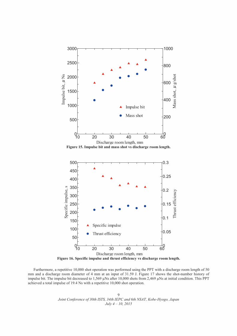
Figures 15 and 16 show experimental results. The impulse bit increased with increasing discharge room length. This is because the mass shot increased when the discharge room length became longer. On the other hand, the specific impulse decreased. It is shown that the performance approaches that of electromagnetic PPT with decreasing discharge room length. This high-power PPT achieved initial performances of impulse bits of 1,794-2,600 μNs, specific impulses of 352-464 s and thrust efficiencies of 12-14 % at 31.59 J with discharge room lengths between 20 mm and 50 mm.
(c)Schematic view
Figure 14. Experimental PPT.
Table 4. Experimental conditions. Discharge room diameter mm 4 Discharge room length mm 20/25/30/35/40/45/50
Nozzle(Cathode) diameter mm 20 Nozzle(Cathode) length mm 18
Capacitance μF 19.5 Charging voltage kV 1.8
Input energy J 31.59
(a) Thruster overview
(b) Operation (Discharge room length: 40mm)
Joint Conference of 30th ISTS, 34th IEPC and 6th NSAT, Kobe-Hyogo, Japan
July 4 – 10, 2015
9
Furthermore, a repetitive 10,000 shot operation was performed using the PPT with a discharge room length of 50 mm and a discharge room diameter of 4 mm at an input of 31.59 J. Figure 17 shows the shot-number history of impulse bit. The impulse bit decreased to 1,569 μNs after 10,000 shots from 2,469 μNs at initial condition. This PPT achieved a total impulse of 19.4 Ns with a repetitive 10,000 shot operation.
10 20 30 40 50 600
50
100
150
200
250
300
350
400
450
500
0
0.05
0.1
0.15
0.2
0.25
0.3
Discharge room length, mm
Spec
ific
impu
lse,
s
Thru
st e
ffic
ienc
y
Specific impulse
Thrust efficiency
Figure 16. Specific impulse and thrust efficiency vs discharge room length.
10 20 30 40 50 600
500
1000
1500
2000
2500
3000
0
200
400
600
800
1000
Discharge room length, mm
Impu
lse
bit,
Ns
Mas
s sho
t, g/
shot
Impulse bit
Mass shot
Figure 15. Impulse bit and mass shot vs discharge room length.

Joint Conference of 30th ISTS, 34th IEPC and 6th NSAT, Kobe-Hyogo, Japan
July 4 – 10, 2015
10
B. Multi-discharge-room electrothermal PPT As the PPT system for the 2nd PROITERES satellite, a longtime operation system is required for changing 200-400 km in altitude on near-earth 200-400 km. Therefore, a new PPT system with Multi-Discharge-Room electrothermal PPT (MDR-PPT) was developed. The MDR-PPT has the plural discharge rooms. An ignitor is mounted in each discharge room. The MDR-PPT can change a firing discharge room by selecting the igniter. The 1st MDR-PPT has eight discharge rooms, as shown in Fig. 18. A repetitive 1,000 shot operation test was performed using the 1st MDR-PPT at an input energy of 31.59 J. Table 5 shows experimental conditions of the test.
Figure 18. 1st MDR-PPT.
0 2000 4000 6000 8000 100000
500
1000
1500
2000
2500
3000
Shot number
Impu
lse
bit,
Ns
Figure 17. Results of repetitive 10,000 shot operation.

Joint Conference of 30th ISTS, 34th IEPC and 6th NSAT, Kobe-Hyogo, Japan
July 4 – 10, 2015
11
Figure 19 shows the photograph of the 1st MDR-PPT after the test. It is shown that unexpected discharges were induced in some discharge rooms in which firing was not selected. The following three causes were inferred. 1) The plasma which was generated in the 1st MDR-PPT was leaked from a gap between the propellant and the nozzle or the anode. 2) Around plasma plume, unexpected multi-ignitions occurred because of short distance between discharge rooms. 3) Excessive ablation of propellant occurred by high-temperature with a repetitive operation, resulting in short circuit between discharge rooms.
The 2nd MDR-PPT was developed under consideration of those causes to prevent the unexpected discharge. The
structure and the firing of the 2nd MDR-PPT are shown in Figs. 20 and 21. The 2nd MDR-PPT has seven discharge rooms and a PTFE body. A nozzle, a propellant and an anode respectively are mounted in the PTFE body and are sealed with two pressing boards. With this structure, airtightness of the 2nd MDR-PPT was improved. In addition, an improvement of cooling performance is expected with two pressing boards. A repetitive 1,000 shot operation test was performed using the 2nd MDR-PPT at an input energy of 31.59 J and a frequency of 0.5 Hz. Table 6 shows experimental conditions.
Table 5. Experimental conditions. Discharge room diameter mm 5 Discharge room length mm 10
Nozzle(Cathode) diameter mm 7 Nozzle(Cathode) length mm 19
Capacitance μF 19.5 Charging voltage kV 1.8
Input energy J 31.59
Figure 19. 1st MDR-PPT after a repetitive operation test.
Discharge room (select firing)
Discharge rooms (not select firing)

Joint Conference of 30th ISTS, 34th IEPC and 6th NSAT, Kobe-Hyogo, Japan
July 4 – 10, 2015
12
Pressing board : Brass
Nozzle : Brass
Propellant: PTFE
Anode : Copper
Body: PTFE
Pressing board : Copper
(a) Component view
(b) Thruster overview
Figure 20. Structure of 2nd MDR-PPT.
Figure 21. Operation of 2nd MDR-PPT.
Joint Conference of 30th ISTS, 34th IEPC and 6th NSAT, Kobe-Hyogo, Japan
July 4 – 10, 2015
13
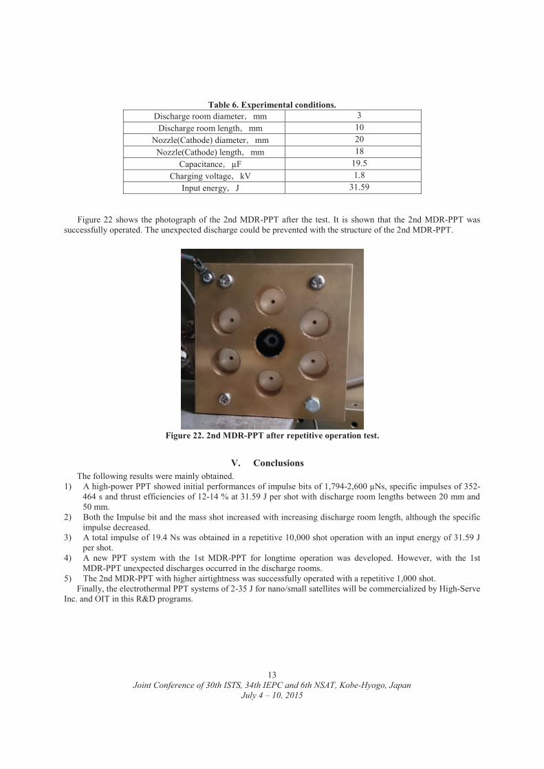
Figure 22 shows the photograph of the 2nd MDR-PPT after the test. It is shown that the 2nd MDR-PPT was successfully operated. The unexpected discharge could be prevented with the structure of the 2nd MDR-PPT.
V. Conclusions The following results were mainly obtained.
1) A high-power PPT showed initial performances of impulse bits of 1,794-2,600 μNs, specific impulses of 352-464 s and thrust efficiencies of 12-14 % at 31.59 J per shot with discharge room lengths between 20 mm and 50 mm.
2) Both the Impulse bit and the mass shot increased with increasing discharge room length, although the specific impulse decreased.
3) A total impulse of 19.4 Ns was obtained in a repetitive 10,000 shot operation with an input energy of 31.59 J per shot.
4) A new PPT system with the 1st MDR-PPT for longtime operation was developed. However, with the 1st MDR-PPT unexpected discharges occurred in the discharge rooms.
5) The 2nd MDR-PPT with higher airtightness was successfully operated with a repetitive 1,000 shot. Finally, the electrothermal PPT systems of 2-35 J for nano/small satellites will be commercialized by High-Serve
Inc. and OIT in this R&D programs.
Figure 22. 2nd MDR-PPT after repetitive operation test.
Table 6. Experimental conditions. Discharge room diameter mm 3
Discharge room length mm 10 Nozzle(Cathode) diameter mm 20
Nozzle(Cathode) length mm 18 Capacitance μF 19.5
Charging voltage kV 1.8 Input energy J 31.59

Joint Conference of 30th ISTS, 34th IEPC and 6th NSAT, Kobe-Hyogo, Japan
July 4 – 10, 2015
14
References 1Ikeda, T., Yamada, M., Shimizu, M., Fujiwara, T., Tahara, H., and Satellite R&D Team of Students and Faculty Members of OIT, “Research and Development of an Attitude Control System for Osaka Institute of Technology Electric-Rocket-Engine onboard Small Space Ship,” 27th International Symposium on Space Technology and Science, Tsukuba, Japan, Paper No. ISTS 2009-s-02f, 2009. 2Yamada, M., Ikeda, T., Shimizu, M., Fujiwara, T., Tahara, H., and Satellite R&D Team of Students and Faculty Members of OIT, “Progress of Project of Osaka Institute of Technology Electric-Rocket-Engine onboard Small Space Ship,” 27th International Symposium on Space Technology and Science, Tsukuba, Japan, Paper No. ISTS 2009-s-05f, 2009. 3Yamada, M., Ikeda, T., Fujiwara, T., and Tahara, H., “Project of Osaka Institute of Technology Electric-Rocket-Engine onboard Small Space Ship,” 31st International Electric Propulsion Conference, University of Michigan, Ann Arbor, Michigan, USA, Paper No. IEPC-2009-051, 2009. 4Tahara, H., Ishii, Y., Tanaka, M., Naka, M., and Watanabe, Y., “Flowfield Calculation of Electrothermal Pulsed Plasma Thrusters for the PROITERES Satellite,” 32nd International Electric Propulsion Conference, Kurhaus, Wiesbaden, Germany, Paper No. IEPC-2011-037, 2011. 5Araki, S., Ikeda, T., Ozaki, J., Nishizawa, M., Inoue, Y., Iguchi, T., and Tahara, H., “Development of an Attitude Control System for Nano-Satellite PROITERES,” 28th International Symposium on Space Technology and Science, Okinawa Convention Center, Ginowan-City, Okinawa, Japan, Paper No. ISTS 2011-j-21s, 2011. 6Nishizawa, M., Ikeda, T., Ozaki, J., Tahara, H., Watanabe, Y., Enoguchi, A., and Takryama, N., “Development of a High-Resolution Camera System onboard Nano-Satellite PROITERES,” 28th International Symposium on Space Technology and Science, Okinawa Convention Center, Ginowan-City, Okinawa. Japan, Paper No. ISTS 2011-n-08, 2011. 7Takagi, H., Yamamoto, T., Ishii, Y., and Tahara, H., “Performance Enhancement of Electrothermal Pulsed Plasma Thrusters for Osaka Institute of Technology Electric-Rocket-Engine onboard Small Space Ship,” 27th International Electric Propulsion Conference, Tsukuba, Japan, Paper No. ISTS 2009-b-16, 2009. 8Takagi, H., Yamamoto, T., Ishii, Y., and Tahara, H., “Performance Enhancement of Electrothermal Pulsed Plasma Thrusters for Osaka Institute of Technology Electric-Rocket-Engine onboard Small Space Ship,” 31th International Electric Propulsion Conference, University of Michigan, Ann Arbor, Michigan, USA, Paper No. IEPC-2009-254, 2009.
9Kisaki, S., Ikeda T., Inoue, Y., Egami, N., and Tahara, H., “Development of Highly-Functional Nano/Small Satellites with Pulsed Plasma Engines,” Int. Conf. on Renewable Energy Research and Applications (ICRERA), Best Western Premier Hotel Nagasaki (Nagasaki-City, Nagasaki), Japan, 2012.
10Egami, N., Matsuoka, T., Sakamoto, M., Inoue, Y., Ikeda T., “R&D,Launch and Initial Operation of the Osaka Institute of Technology 1st PROITERES Nano-Satellite with Electorothermal Pulsed Plasma Thrusters and Development of the 2nd satellite” 33nd International Electric Propulsion Conference, The George Washington University, 2013, Paper No. IEPC-2013-100, 2013.
11Naka, M., Hosotani, R., Tahara, H., and Watanabe, Y., “Development of Electrothermal Pulsed Plasma Thruster System Flight-Model for the PROITERES Satellite” 32nd International Electric Propulsion Conference (32nd IEPC), Kurhaus, Wiesbaden, Germany, Paper No. IEPC-2011-034, 2011. 12Muraoka, R., Kisaki, S., Tanaka, M., Tahara, H., and Wakizono, T., “Research and Development of Osaka Institute of Technology PROITERES Nano-Satellite Series with Electric Rocket Engines,” 33nd International Electric Propulsion Conference, George Washington University, USA, Paper No. IEPC-2013-103, 2013. 13Kisaki, S., Muraoka, R., Huanjun, C., Tanaka, M., Tahara, H., and Wakizono, T., “Research and Development of Electrothermal Pulsed Plasma Thruster Systems onboard Osaka Institute of Technology PROITERES Nano-Satellites,” 33nd International Electric Propulsion Conference, George Washington University, USA, Paper No. IEPC-2013-97, 2013. 14Kamimura, T., Tahara, H., “R&D, Launch and Initial Operation of the Osaka Institute of Technology 1st PROITERES Nano-Satellite with Electrothermal Pulsed Plasma Thrusters and Development of the 2nd and 3rd Satellites,” AIAA Propulsion and Energy Forum and Exposition 2014, Cleveland Convention Center, USA, Paper No. AIAA-2014-3609, 2014. 15Fujita, R., Muraoka, R., Hunnjun, C., Kisaki, S., Tanaka, T., and Tahara, H., and Wakizono, T., “Development of Electrothermal Pulsed Plasma Thruster Systems onboard Osaka Institute of Technology PROITERES Nano-Satellites,” AIAA Propulsion and Energy Forum and Exposition 2014, Cleveland Convention Center, USA, Paper No. AIAA-2014-3610, 2014.
16Fujita, R., Muraoka, R., Kanaoka, K., Hunnjun, C., Kisaki, S., Tanaka, T., and Tahara, H., and Wakizono, T., “Flowfield Simulation and Performance Prediction of Electrothermal Pulsed Plasma Thrusters onboard Osaka Institute of Technology PROITERES Nano-Satellite Series,” 30th International Symposium on Space Technology and Science 34th International Electric Propulsion Conference and 6th Nano-satellite Symposium, Hyogo-Kobe, Japan, Paper No. IEPC-2015-207/ISTS-2015-b-207, 2015.