research and development of materiel · amc pamphlet itm c-i47 amcp 706-341 ... research and...
TRANSCRIPT
AMC PAMPHLET itM C-I47 AMCP 706-341 THIS EA REPRINTWITHOUTCHANGE OF ORDP 20-341
RESEARCH AND DEVELOPMENT OF MATERIEL
ENGINEERING DESIGN HANDBOOK
CARRIAGES AND MOUNTS SERIES CRADLES
REDSTOME SCIENTIFIC INFORMATIONCENTER
5 05 0 00 97074 5
HEADQUARTERS, U. S.ARMY MATERIEL COMMAND SEPTEMBER 1963
HEADQUARTERS UNITED STATES ARMY MATERIEL COMMAND
WASHINGTON 25, D. C.
30 September 1963
AMCP 706-341, Cradles, forming part of the Carriages and i
Mounts Series of the Army Materiel Command Engineering Design Handbook Series, is published for the information and guidance of all concerned.
(AMCRD)
FOR THE COMMANDER:
SELWYN D. SMITH, JR. Major General, USA Chief af Staff
OFFICIAL:
^^L R. O. DAVIDSON Colonel, GS Chief, Admillustrative Office
DISTRIBUTION: Special
PREFACE
This handbook on Cradles has been prepared as one of a series on Car- riages and Mounts. It presents information on the fundamental operating principles and design of cradles.
This handbook was prepared under the direction of the Ordnance Engi- neering Handbook Office, Duke University, under contract to the Office of Ordnance Research. Text and line illustrations were prepared by The Franklin Institute, Philadelphia, Pennsylvania, under subcontract to the Ordnance Engineering Handbook Office. Technical assistance was rendered by the Ordnance Weapons Command.
TABLE CF CONTENTS
Page
PREFACE i
LIST OF ILLUSTRATIONS v
LIST OF SYMBOLS vi
I. INTRODUCTION
A. General 1 B. Purpose 1 C. Functions 1
II. EQUIPMENT ASSOCIATED WITH CRADLES
A. Recoil Mechanism 1 B. Trunnions 2 C. Elevating Mechanism 2 D . Equilibrator 2
III. TYPES OF CRADLE
A. The U-Type Cradle 2 B. The O-Type Cradle 3 C. Other O-Type Cradles 4
IV. DESIGN PROCEDURES
A. Structure to Carry the Various Forces 5 1. Recoil Attachment to the Cradle 5 2. Equilibrator Attachment 7 3. Elevating Arc 7 4. Attachment for Transmitting Rifling Torque 10
B. Sliding Surfaces of U-Type Cradle 11 1. Load Analysis 11 2. Construction 12
C. Sliding Surface of O-Type Cradle 15 D. Effect of Friction on Sliding Surfaces 15 E. Effect of Temperature Variation on Sliding Surfaces 15 F. Location and Design of Trunnions 16 G. Strength Requirements 17
1. Trunnion Hubs 18 2. Recoil Mechanism Attachment Bracket 20

TABLE OF CONTENTS (Concluded)
Page V. DESIGN PRACTICE
A. Structure 21 B. Suggested Materials for Cradle 22 C. Manufacturing Procedures 22 D. Maintenance 22
VI. SAMPLE PROBLEM. O-TYPERADLE
A. Load Analysis 23 B. Elevating Arc 24 C. Recoil Mechanism Attachment Bracket 25 D. Cradle Body 25 E. Trunnion Analysis 31
VIE SAMPLE PROBLEM. U-TYPECRADLE
A. Load Analysis 34 1. Rails and Slides 34 2. Equilibrator Load 35 3. Elevating Gear Load 36 4. Trunnion Loads., 37
B. Cradle Body 38 1. Shear and Moment Chart 38 2. Stress and Deflection 38
GLOSSARY 40
REFERENCES 42
INDEX 43
IV

LIST OF ILLUSTRATIONS
Figure Page 1 Weapon Showing Typical Components 1 2 U-Type Cradle With Attached Recoil Mechanism 3 3 U-Type Cradle With Integral Recoil Mechanism 3 4 O-Type Cradles 4 5 Forces on Recoiling Parts 6 6 Equilibrator Attachments, Cantilever Type 7 7 Equilibrator Attachment, Simple Beam Type 7 8 External Loads on Cradle, Single Recoil System 8 9 External Loads on Cradle. Double Recoil System 9
10 Elevating Arc 10 11 Forces Due to Rifling Torque 10 12 Load Distribution on Rails, U-Type Cradle 12 13 End View of Sliding Structure Showing Bearing Liner 13 14 Tube Assembly Showing Rails 13 15 Sleigh With Attached Recoil Cylinders, Gun Tube Secured With
Yokes 13 16 Sleigh With Integral Recoil Cylinders 14 17 Slide and Guide Showing Assumed Deflections 14 18 Trunnion Location With Respect to Recoil Forces 16 19 Load Distribution on Trunnion Structure 18 20 Gusset Reinforced Trunnion Housings 19 21 Equivalent Ring Loading Conditions 20 22 Loads on Elevating Arc 25 23 Recoil Bracket and Loading Diagram 26 24 Cradle Body Showing Applied Loads and Reactions 27 25 Shear and Moment Diagram, Cradle Body 28 26 Isolated Ring Section of Cradle 28 27 Recoil Bracket With Gusset Reinforcement 29 28 Trunnion Loads and Reactions 31 29 Gusset Load Diagram 32 30 Trunnion Housing With Gusset Reinforcement 32 31 Trunnion Housing and Cross Section of Cradle 35 32 Applied Loads on Cradle 36 33 Loads on Elevating Arc 36 34 M/I Diagram 39

LIST OF SYMBOLS
A 6 bore area a linear acceleration of projectile at peripheral acceleration of projectile a2 acceleration of the secondary recoiling
mass in a double recoil system c distance from vertical axis to outermost
fiber CG center of gravity d distance of neutral axis from base of
section E modulus of elasticity FA trunnion force parallel to axis of bore Fa inertia force of recoiling parts in a single
recoil system or of the primary recoiling parts in a double recoil system
Fc inertia force of cradle Fg equilibrator force Fg propellant gas force Fa trunnion force normal to axis of bore FT resultant trunnion force Fi inertia force of primary recoiling parts
due to secondary recoil Fi inertia force of secondary recoiling parts A frictional resistance of front bearing f2 frictional resistance of rear bearing H horizontal force of load / moment of inertia of section /, mass moment of inertia of projectile K total resistance to recoil KR force provided by the recoil mechanism K, slenderness factor k radius of gyration of projectile L length or distance M moment MT moment about trunnion Me moment at the load mp mass of projectile mi mass of primary recoiling parts
m2 mass of secondary recoiling parts Nr twist of rifling in calibers per turn P0 propellant gas pressure p induced pressure of shrink fit R secondary recoil force; radius Ri radius of bore Rg elevating gear load RP pitch radius of elevating arc R^ normal reaction of front bearing fi2 normal reaction of rear bearing r equilibrator moment arm; radius Sf factor of safety Tr rifling torque V vertical force or load W weight, recoiling parts, singlerecoil system;
induced ring load weight of cradle weight of recoiling parts in a single re- coil system or of the primary recoiling parts in a double recoil system weight of secondary recoiling parts in a double recoil system unit load section modulus angular acceleration of projectile deflection; radial interference
AD diametral deflection e angle of elevation;
location of ring load Qr helix angle of rifling p co effi ci ent of fr i cti on v Poisson's ratio <J stress, general
bearing stress compressive stress
at tensile stress T shear stress
w Z a A
angular deflection;
a,-.
VI
CARRIAGES AND MOUNTS SERIES
CRADLES*
I. INTRODUCTION
A. GENERAL
1. This is one of a series of handbooks on Carriages and Mounts. This handbook deals with the design of cradles.
B. PURPOSE
2. The cradle was first introduced in Ordnance Corps Pamphlet ORDP 20-340f where it was discussed as one of the elements that make up a carriage or mount. This handbook deals specifically with the cradle. The various types are discussed along with their components and pertinent design data.
it Prepared by Martin Regina, Laboratories for
Research and Development of The Franklin Institute. t Reference 1. References are found at the end of
this handbook.
C. FUNCTIONS
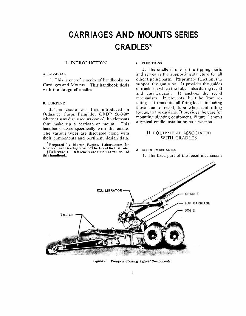
3. The cradle is one of the tipping parts and serves as the supporting structure for all other tipping parts. Its primary function is to support the gun tube. It provides the guides or tracks on which the tube slides during recoil and counterrecoil. It anchors the recoil mechanism. It prevents the tube from ro- tating. It transmits all firing loads, including those due to recoil, tube whip, and rifling torque, to the carriage. It provides the base for mounting sighting equipment. Figure 1 shows a typical cradle installation on a weapon.
11. EQUIPMENT ASSOCIATED WITH CRADLES
A. RECOIL MECHANISM
4. The fixed part of the recoil mechanism
EQUILIBRATOR
TRAILS
Figure 7. Weapon Showing Typical Components
is attached to the cradle and the movable por- tions are attached to the recoiling parts. There are, in general, two basic arrangements for the recoil mechanism. One has the recoil cylinder and recuperator fixed to the cradle and the piston rod fixed to the gun lug or breechblock. The other arrangement fixes the recoil cylinder and recuperator to the gun and the rod to the cradle. In the former case, the cylinder and recuperator are either integral parts of the cradle or separate parts rigidly attached to it. It is well to have the recoil mechanism in- stalled as near as possible to the tube, not only for compactness but also for lower bending moments on the cradle which are axiomatic to lower stresses and, therefore, lighter structure.
D, EQUILIBRATOR
7. One end of the equilibrator is attached to the top carriage and the other to the cradle. A large turning radius about the trunnion is desirable for the equilibrator as it lowers the forces. Hence, a more efficient design results. The attachment on the cradle may be at any convenient location on the structure or on the elevating arc, provided that clearances and strength requirements are met. Equilibrator design is discussed in Ordnance Corps Pamph- let ORDP 20-345.*
III. TYPES OF CRADLE
B. TRUNNIONS
5. The trunnions are considered to be com- ponents of the cradle whether the trunnion bearings are located on the side frames or in the cradle itself. The trunnions, through which the firing loads are transmitted, are the main attachment to the top carriage and also serve as the pivot about which the tipping parts rotate during elevation. In the plan view, their axis should lie normal to the direction of recoil. In the side view, the trunnion axis should be located on or near the line parallel to the bore and passing through the center of gravity of the recoiling parts. This reduces tipping moments during firing and relieves the elevating arc of large loads.
C. ELEVATING MECHANISM
6. The elevating mechanism terminates at the elevating arc which is a gear segment rigidly attached to the cradle. It is here that the torque required to elevate is applied to the tipping parts. The pitch radius of the ele- vating arc is centered at the trunnions and should be as large as possible and still remain compatible with the size of the rest of the structure. A large radius results in small gear tooth loads and less effort to elevate the gun. Also, if the arc is large, the attachments to the cradle can be located farther apart and, al- though the torque transmitted to the tipping parts remains unaffected, the corresponding loads at the attachment points are decreased.
8. There are two basic types of cradle, designated according to the general form of cross section as the U-type and the 0-type. Each has its own method of seating the gun tube. The U-type seats the tube on top and retains it by guides. The 0-type holds the tube in a hollow cylinder whose inner wall con- forms to the mating portion of the tube.
A. THE U-TYPE CRADLE
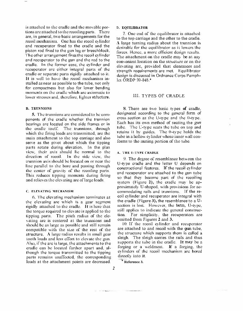
9. The degree of resemblance between the U-type cradle and the letter U depends on constructional features. If the recoil cylinder and recuperator are attached to the gun tube so that they become part of the recoiling system (Figure 2), the cradle may be ap- proximately U-shaped, with provisions for ac- commodating rails and trunnions. If the re- coil cylinder and recuperator are integral with the cradle (Figure 3), the resemblance to a U- section is lost. However, the term, U-type, still applies to indicate the general construc- tion. For simplicity, the recuperators are omitted from Figures 2 and 3.
10. If the recoil cylinder and recuperator are attached to and recoil with the gun tube, the structure which supports them is called a sleigh. The sleigh carries the rails and thus supports the tube in the cradle. It may be a forging or a weldment. If a forging, the cylinders of the recoil mechanism are bored directly into it.
Reference 3.
~22L
LE yi3s
löösH BREECH BLOCK
» i -
- RFCOIL
CYLINDER SECTION A-A
Figure 2. U-Type Cradle With Attached Recoil Mechanism
RECOIL CYLINDER
GUN TUBE I \ '. ', WW W\ WWW \^ ?v^v
BREECH- BLOCK
W.W.'W .'.''^^SSN-JW ^TW
^ RECOIL ROD SECTION A-A
Figure 3. U-Type Cradle With Integral Recoil Mechanism
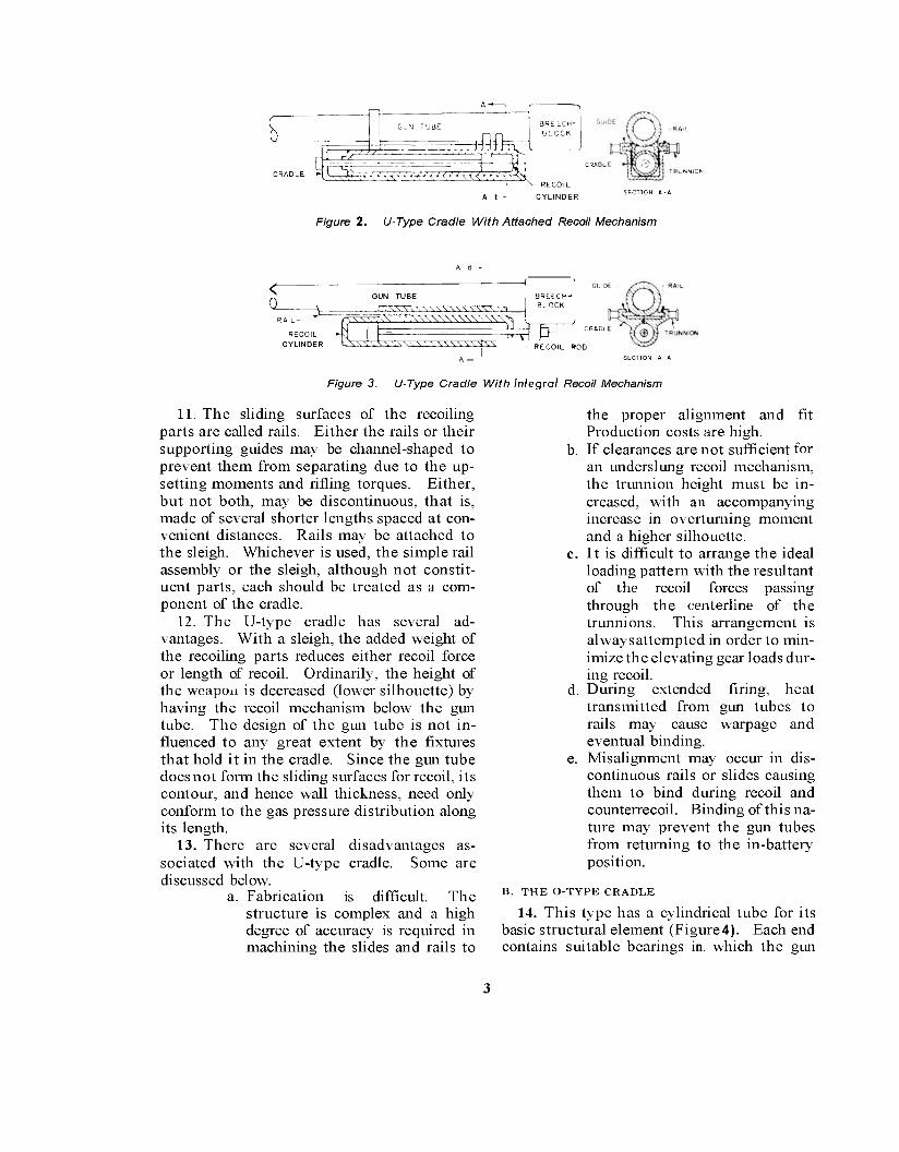
11. The sliding surfaces of the recoiling parts are called rails. Either the rails or their supporting guides may be channel-shaped to prevent them from separating due to the up- setting moments and rifling torques. Either, but not both, may be discontinuous, that is, made of several shorter lengths spaced at con- venient distances. Rails may be attached to the sleigh. Whichever is used, the simple rail assembly or the sleigh, although not constit- uent parts, each should be treated as a com- ponent of the cradle.
12. The U-type cradle has several ad- vantages. With a sleigh, the added weight of the recoiling parts reduces either recoil force or length of recoil. Ordinarily, the height of the weapon is decreased (lower silhouette) by having the recoil mechanism below the gun tube. The design of the gun tube is not in- fluenced to any great extent by the fixtures that hold it in the cradle. Since the gun tube does not form the sliding surfaces for recoil, its contour, and hence wall thickness, need only conform to the gas pressure distribution along its length.
13. There are several disadvantages as- sociated with the U-type cradle. Some are discussed below.
a. Fabrication is difficult. The structure is complex and a high degree of accuracy is required in machining the slides and rails to
the proper alignment and fit Production costs are high.
b. If clearances are not sufficient tor an underslung recoil mechanism, the trunnion height must be in- creased, with an accompanying increase in overturning moment and a higher silhouette.
c. It is difficult to arrange the ideal loading pattern with the resultant of the recoil forces passing through the centerline of the trunnions. This arrangement is alwaysattempted in order to min- imize the elevating gear loads dur- ing recoil.
d. During extended firing, heat transmitted from gun tubes to rails may cause warpage and eventual binding.
e. Misalignment may occur in dis- continuous rails or slides causing them to bind during recoil and counterrecoil. Binding of this na- ture may prevent the gun tubes from returning to the in-battery position.
B. THE O-TYPE CRADLE
14. This type has a cylindrical tube for its basic structural element (Figure4). Each end contains suitable bearings in. which the gun

CRADLE WALL
SSHXg 3: GUN TUBE
SLIDING SURFACES
313:
RECOIL PISTON
AV\\\\\\X\
^ %\ ^ ^ v ^ ^^-
BREECH- BLOCK
LTJ TRUNNION
RECOIL CYLINDER —' A-
(a) EXTERNAL RECOIL MECHANISM TYPE
SECTION A-A
CRADLE - RECOIL CYLINDER COMBINATION
KEY—x A-*-,
dt /////////////// YK ^,KVft ft ft ft a ftB
/-SLIDING SURFACES
GUN TUBE
RECOIL PISTON-
y V) y y u •»/////SS//////// a
BREECH- BLOCK
At-' TRUNNION SECTION A-A
(b) CONCENTRIC RECOIL MECHANISM TYPE
Figure 4. O-Type Cradles
tube slides. The outside surface of the tube is cylindrical for a considerable length forward of the breech. This surface is machined smooth and the tube itself serves as its own slide, the bearings functioning as guides during recoil and counterrecoil. A key transmits the rifling torque to the cradle to prevent rotation of the tube. Brackets or some similar structure are provided on the cylindrical portion of the cradle to attach the recoil mechanism, the trunnions, and the elevating arc.
15. The use of an 0-type cradle offers sev- eral advantages. It is convenient to locate the trunnions on the line of action of the recoiling parts to relieve the elevating gear of firing loads. The structure is comparatively light which helps to increase mobility. Use of the 0-type cradle does not require the sliding surfaces to be attached to the gun tube, thus eliminating this fabrication problem. The cylindrical surfaces reduce machining prob- lems and provide more accurate alignment. A choice of a favorable location is available for the recoil mechanism. When the recoil mech- anism is on the top of the tube, it does not pre- sent clearance problems while the tipping parts are being elevated.
16. There are several disadvantages inherent to the 0-type cradle. The sliding surface of the gun tube is exposed to the weather, al- though this can be eliminated by the installa- tion of a shield. It dictates, to some extent, the diameter of the tube forward of the chamber because it cannot be tapered along the sliding surface. If the forward portion of the sliding surface is made smaller in diameter, then two sleeve bearings of different diameters are necessary. The effects of heating the gun tube can be serious if the expansion exceeds the clearances in the bearings. The clearances which must be provided to avoid binding may result in sloppy fits while the gun is cold. An- other clearance problem stems from the trans- port condition, where road clearances may be critical with the recoil mechanism attached to the top of the gun tube,
C. OTHER 0-TYPE CRADLES
17. Another form of 0-type cradle is the con- centric recoil mechanism type (see Figure 4b). In outward appearance, it resembles the con- ventional type but, unlike the conventional type, the cradle forms the outer recoil cylinder

and fits concentrically around the gun lube. The internal elements of the recoil mechanism fit between outer diameter of the gun tube and inner diameter of the cradle. Due to the com- pactness of the assembly, this type cradle is usually found in tanks where space is at a premium. A big advantage offered by this type is that the recoil mechanism is on the axis of the gun bore which is also the line of action of the recoiling parts and can readily be made the location of the trunnions. Consequently, reactions to the moments at the trunnion bearings are negligible. Frictional forces are minimal, produced only by the normal com- ponent of the weight of the recoiling parts.
IV. DESIGN PROCEDURES
A. STRUCTURETO CARRY THE VARIOUS FORCES
18. In its role of supporting structure for the other tipping parts, the cradle is subjected to a number of forces which it must transmit to the carriage. The predominant one is the recoil force. Others include the equilibrator force, the elevating gear reaction due to tipping moments, and the reaction on the key or guides due to the rifling torque. During the early stages of design, approximate loads are adequate and are readily available. When the design is in its final stages, the loads should be accurate. However, first approximations, in all likelihood, will be close enough to the final values so that only minor revisions in the struc- ture will be necessary.
1. Recoil Attachment to the Cradle
19. When the recoil mechanism housing is integral with the cradle, the recoil forces are applied through it and no additional support- ing structure is necessary. If it is merely at- tached to the cradle, appropriate yokes or sim- ilar structures are needed to carry its force to the cradle. If the recoil mechanism is at- tached to and moves with the recoiling parts, the recoil rod is fixed to the cradle, sometimes by an adapter or sometimes by a nut threaded to the end of the rod. The rod, in this case, is attached to the front of the cradle where local
reinforcement of the structure may be neces- sary to carry the load.
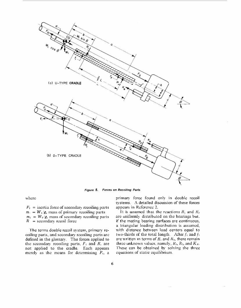
20. The method for calculating the approx- imate recoil force is found in Reference 2. This force comprises the sliding frictional resistance of the recoiling parts and the resist- ance provided by the recoil mechanism. Sketches in Figure 5 show how the applied loads and corresponding recoil force are dis- tributed on the U-type and 0-type cradles. Figure 5a has those of a single recoil system and Figure 5b has those of a double recoil system. The definitions of the symbols in Figure 5 follow.
CG = the center of gravity of the recoiling parts
F„ -- inertia force of the recoiling parts in a single recoil system, or of the primary recoiling parts in a double recoil system
F„ = propellant gas force Fi = inertia force of primary recoiling parts
due to secondary recoil acceleration U = frictional resistance of front bearing f-i = frictional resistance of rear bearing Kit = force provided by recoil mechanism R\ = normal reaction of front bearing R> = normal reaction of rear bearing Wi = weight of recoiling parts in a single re-
coil system or of the primary recoiling parts in a double recoil system
6 = angle of elevation K = total resistance to recoil (recoil force) ß = coefficient of friction
f, = iiR, (la) /., = MR2 (lb>
K = Ku +A +/, (2) Fa = F„+ W, sin 8 - K - F, cos 8 (3)
The force f\ occurs in double recoil systems where
Wi Ft = a« = midi (4)
g
and the acceleration of the secondary recoiling mass is
F, a, =
m.
K cos e 1
R Wi cos 0_sin 8 (mi/m2) siii-6
Obtained from Reference 2, Equation 88.
W
(6)"
(b) O-TYPE CRADLE
Figure 5. Forces on Recoiling Parts
where
F2 = inertia force of secondary recoiling parts m, = Wi/g, mass of primary recoiling parts m2 = W2/g, mass of secondary recoiling parts R = secondary recoil force
The terms double recoil system, primary re- coiling parts, and secondary recoiling parts are defined in the glossary. The forces applied to the secondary recoiling parts, F2 and R, are not applied to the cradle. Each appears merely as the means for determining Fu a
primary force found only in double recoil systems. A detailed discussion of these forces appears in Reference 2.
It is assumed that the reactions Rt and fi2
are uniformly distributed on the bearings but, if the mating bearing surfaces are continuous, a triangular loading distribution is assumed, with distance between load centers equal to two-thirds of the total length. After /[ and /2
are written in terms of fii and R2, there remain three unknown values, namely, Ru R2, and KR. These can be obtained by solving the three equations of static equilibrium.

— EQUtLBRATOR-
EQUILIBRATOR SHAFT
(o) EQUILIBRATOR ATTACHMENT ON CRADLE STRUCTURE
- EQUILIBRATOR -7 SHAFT
EQUILI8RAT0R
ELEVATING ARC
(b) EQUILIBRATOR ATTACHMENT ON ELEVATING ARC
Figure 6. Equilibrator Attachments, Cantilever Type
ZV = 0 (7a) ZH = 0 (7b) ZM = 0 (7c)
Assume that the axis of the bore is hori- zontal and take the moments at a convenient point such as the intersection of/- and R-.
2. Equilibrator Attachment
21. Each equilibrator, whether one or two to the weapon, pivots on a shaft attached to the cradle. If two are used, the shafts are usually cantilevered from each side of the structure
(Figure 6a) or the elevating arc (Figure 6b). If one is used, each end of the shaft is supported by the structure (Figure 1).
22. For any given angle of elevation, the equilibrator force is the one required to pro- duce the moment which balances the weight moment of the tipping parts. Although actual equilibrator forces do not always equal the theoretically required ones, differences are small enough that the structure is not affected. Hence, for design purposes, the theoretical value will be used to simplify the load analysis. From Figures 8 or 9 the equilibrator force is
„ Wlr1cos(9 + 0,) + W>, cos (0 + <M b v = r
{ii>
where W\ = weight of recoiling parts W, = weight of cradle.
In Figure 8, 4>2 is negative It is apparent that, before the preliminary
design of the cradle is completed, the equilibra- tor geometry, at least a preliminary one, must be determined in order to compute its force (see Reference 3).
3. Elevating Arc
23. The attachment of the elevating arc to the cradle should be through a well-fitting, rigid joint because the meshing of gear teeth is involved. Improper meshing of the gears will prove detrimental in one or all of three ways; poor load distribution may overstress the teeth, excessive wear may occur, and gear efficiency may decrease, thus requiring an in- creased torque at the handwheel. The attach-
SLIDE
ATTACHMENT BRACKET
EQUILIBRATOR SHAFT EQUILIBRATOR
Figure 7. Equilibrator Attachment, Simple Beam Type

RESOLUTION OF FORCES
Fg =
FA =
FN =
Fg =
RP =
W, =
wc = wt = 0 -- e = Figure
INERTIA FORCE OF RECOILING PARTS
EQUILIBRATOR FORCE
PROPELLANT GAS FORCE
TRUNNION REACTION PARALLEL TO BORE
TRUNNION REACTION NORMAL TO BORE
ELEVATING GEAR LOAD
PITCH RADIUS OF ELEVATING GEAR
WEIGHT OF RECOILING PARTS
WEIGHT OF CRADLE
WEIGHT OF TIPPING PARTS
PRESSURE ANGLE OF GEAR
ANGLE OF ELEVATION
8. External loads on Cradle, Single Recoil System
CG RECOILING PARTS
FQ = INERTIA FORCE OF PRIMARY RECOILING PARTS
F| = INERTIA FORCE DUE TO SECONDARY RECOIL
FA = TRUNNION REACTION PARALLEL TO BORE
Fc = INERTIA FORCE OF CRADLE
EQUILIBRATOR FORCE
PROPELLANT GAS FORCE
TRUNNION REACTION NORMAL TO BORE
FORCE IN RECOIL ROD
ELEVATING GEAR LOAD
= PITCH RADIUS OF ELEVATING GEAR
= WEIGHT OF PRIMARY RECOILING PARTS
- WEIGHT OF CRADLE
- PRESSURE ANGLE OF GEAR
= ANGLE OF ELEVATION
rE "
Fg =
FN =
KR =
Rg =
Rp =
W, =
w = ß -- e
Figure 9. External loads on Cradle, Double Recoil System
In > r-1 n t n,
Rq
EQUILIBRATOR FORCE
ELEVATING GEAR LOAD
RRH = SHEAR REACTION ON KEY
R = LEFT BOLT REACTION RL
RRR= RIGHT BOLT REACTION
Figure 10. Elevating Arc
ment then must be secured in a manner which will preclude objectionable misalignment under load. This requires close fitting machined surfaces held together by shear connections such as body-bound bolts, keys, pins, or shafts. Figure 10 illustrates the use of a key and bolts. It also shows the loads on the attachments between arc and cradle.
24. The action of equilibrators practically eliminates the gear load except during eleva- tion and recoil. The largest load usually oc- curs during recoil. Only if the trunnions and the center of gravity of the recoiling parts lie on the bore axis will no additional gear load be applied during recoil. Figure 8 illustrates the applied external loads on the cradle for a single recoil system. In a double recoil system, the additional inertia loads i*\ and F, are produced by the secondary recoil acceleration* and are applied horizontally at the centers of gravity of the primary recoiling parts and the cradle (Figure 9). The reaction on the gear, R,„ is computed by taking moments about the trun- nions. The trunnion reactions, parallel and normal'to the bore axis, are found by bringing the force system into equilibrium.
4. Attachment for Transmitting Rifting Torque
25. In addition to supporting the tube, the
* Reference 2, Chapter XI.
(a) U-TYPE CRADLE
(b) 0-TYPE CRADLE
Figure 77. Forces Due to Rifling Torque
cradle must also transmit the rifling torque to the top carriage. Figure 11 shows the torque reactions on the cradle and the distances be- tween load centers.
The approximate rifling torque equation
0.67r2fli!P„ Tr =
Nr (9)
is derived from the basic torque equation
Tr = Iva (9a)
The derivation includes the following sym- bols
Ah = bore area (less rifling groove area) a = linear acceleration of projectile ai = peripheral acceleration of projectile
at the bore F„ = propellant gas force /, = mass moment of inertia of projectile k = radius of gyration of projectile
10
m,, = mass of projectile Nr = twist of rifling, calibers per turn P„ = propellant gas pressure Ri, - radius of bore o 7 - angular acceleration of projectile Or = helix angle of the rifling
A,, = 7r/if, (9b,i F„ = A„P„ (9c i
From the general expression, F„ - m,,a
a = '<<
tan <?r = ^ (9e)
(9d,.
a,
N,
a tan 0r (9f)
Substituting the appropriate terms of Equa- tions 9b, 9c, 9d, and 9e into Equation 9f and collecting terms, we have
Ogi
a. (9h)
mpNr
_ TC-RbPg
rripNr
The value, k- = 0.6Rb is generally accepted as an approximate value. Then
/„ = m„k2 = 0.6m „Ri (9i)
Equation 9 is obtained by substituting the terms of Equations 9h and 9i into Equation 9a. From Figures 11a and lib, the load on the trunnions due to rifling torque is
d, (10)
and, correspondingly, the load on the rails (Figure 11 a) or on the key (Figurellb is
F' dr
Note that the maximum torque occurs when the propellant gas pressure is maximum. For the U-type cradle, the torque is trans- mitted directly to the guides through the rails or the sleigh in the form of vertical forces hav- ing a moment arm equal to the distance from their lines of action to the bore axis (Figure 11a). For the 0-type cradle, the tube is keyed to the cylindrical portion of the cradle. The torque is transmitted through the key and the contacting surface between tube and cradle (Figure 1 lb). The moment arm extends
from the key to the center of the assumed tri- angular distributed load on the projected diameter. For either type cradle, the loads induced by the rifling torque are eventually transmitted to the top carriage by the trun- nion.
B. SLIDING SURFACES OF U-TYPE CRADLE
1. Load Analysis
26. There are two types of force on the slides: the normal forces and the frictiona I forces derived from the normal forces. The normal forces are obtained as reactions to the rifling toryue, to the couple created by the re- coil forces and the inertia of the recoiling parts, and to the weight of the recoiling parts. Thus, the shorter the distances between the forces parallel to the bore axis and the closer the center of gravity is to the midspan of the slides, the smaller will be the forces on the slides. Actually, in single recoil systems, the weight contributes little to the maximum forces; therefore, the center of gravity may fall outside the slides without deleterious ef- fects. However, in double recoil systems, the inertia force due to secondary recoil may pro- duce appreciable loads on the slides, and it be- comes desirable riot to have the center of gravity overhang the sliding surfaces.
27. When calculating the loads on rails and guides, the distribution of bearing pressure should be considered. If the two mating sliding surfaces are continuous, a triangular load distribution is assumed. Triangular load dip tribut ion implies zero clearaw e and linear com- pliance of rails and guides. The assumption of triangular load distribution is subject to change for unusual constructions. If the sliding surfaces arediscontinuous, a trapezoidal distribution is assumed or, if the pads are spaced sufficiently far apart, uniform load dis- tribution is assumed. Figure 12 illustrates these effects. The diagrams represent the re- actions to the couple, M,:, of the recoiling parts. The reactions R\ and R- are calculated by assuming that they are concentrated at the center of the area that represents the dis- tributed load. After the reactions to the couple are found, those resulting from the rifling torque and the normal component of the
V, 2 (8040A) O - n

(a) CONTINUOUS .RAIL
L, S THE DISTANCE TO THE CEHTROID OF THE DISTRIBUTED Uno
(b) DISCONTINUOUS RAIL
Figure 72. load Distribution on Rails, U-Type Cradle
weight are added algebraically as uniformly distributed loads.
28. The maximum bearing pressure is then determined from the completed load diagram. A bearing pressure of 200 to 300 lb in2 is recommended for continuous motion but since motion is not continuous, bearing pressures as high as 500 lb/in2 are permissible. If pres- sures exceed this limit, there is danger of se-
vere wear on the sliding surfaces, requiring early replacement. This condition must be tolerated if no other design resource is avail- able but it usually means added maintenance and should be avoided if at all possible.
2. Construction
29. The sliding structure which supports
12
the recoiling parts consists of male and female members. The male members are called rails or slides and the female members are called guides. These latter are similar to channels in cross section, so that bearing surfaces will
GUIDE
SLEIGH SLIDE
Figure 13. End View of Sliding Structure Showing Bearing Liner
support the rails against either upward > downward loads. Bronze liners with surf.3 : finishes between 32 and 63 microinch rr.ci cover the rails and slides to provide the bears;: surface Figure 13). The guides are unlink but their surfaces are machined to the sam finish as the rails and slides.
30. Rails are usually secured to the tub* The front attachment is to a sleeve or fla ring, either clamped or shrunk on the tal The rear attachment is to a similar ring 01 may be the breech nng. Figure 14 shows typical installation. The rails or guides ma be continuous or discontinuous, if the guid< are discontinuous they are sometimes call - clips. Discontinuity in the sliding surf a ■< is not recommended if contact between the- is broken during the recoil stroke because the difficulty in re-entering the guides dur counterrecoil. The present t rend in design to have continuous rails on the gun tube
31. When a sleigh is used, the gun tube held securely to it by collars or yokes as she - in Figure 15. Figure 16 shows another 1 . sleigh. This one has the recoil cylino
m<rtm^^*^^!!SiK^^
Figure 14. Tube Assembly Showing Rails
J j
CENTER YOKE RONT YOKE
±7 i
L
[*■■- RECUPERATOR
GUIDE
i -—RECOIL-
CYLINDER
Figure 15. Sleigh With Attached Recoil Cylinders, Gun Tube Secured With Yokes
13
LOCKDB WEDGES
IN LOCKING POSITION
WEDGE SCREWS
GUIDE
RECUPERATOR
'-WEDGE
LOCKING BOLT
CYLINDERS
Figure 16. Sleigh With Infegral Recoil Cylinders
integral with the sleigh body. Close fitting mating lugs on tube and sleigh preclude tipping while locking wedges preclude relative longi- tudinal motion. The wedges move laterally and fit into recesses machined in the tube structure. The structure forming the sliding surfaces may be bolted or welded to the sleigh. Sometimes they form an integral part, being machined from the sleigh or cradle structure.
32. The strength of the rail, slide, or guide is determined by the following conservative method of analysis. Assume that the maxi- mum distributed load is constant for a distance of one inch. Isolate a one-inch length of structure with this load and investigate its strength. Thus at Section A-A of Figure 17a, which is one inch deep,
w = lb/in, unit load, maximum intensity F = 1 X w, lb, total load M = Fd, lb-in, bending moment A = 1 X a, in-, area of section in tension
Mc j. F <r, = —j— T -j, lb in2, tensile stress in section
(ID
33. In addition to strength requirements, the sliding members must have ample contact- ing surfaces to insure a reasonable bearing pressure (Paragraph 28). Rut large areas alone may not achieve a reasonable pressure if ensuing deflections cause a reduction in
(a) LOADING DIAGRAM
(b) CANTILEVER BEAM ANALOGY
Figure 77. Slide and Guide Showing Assumed Deflections
contact area, thereby intensifying the pressure. Two types of deflection may occur. One in- volves bending of the vertical members which causes the contacting areas to rotate and thus overload the edges of the bearing. This is il- lustrated by the phantom member in Figure 17a. However, if both members are identically constructed, angular deflections will be equal and the whole contact area remains intact. The other deflection concerns the equivalent cantilever beam of the bearing members as illustrated by the section: 1 view in Figure 17b. This deflection poses a difficult problem for, as the beam deflects, the load immediately becomes redistributed over a smaller space with accompanying higher pressures. Since the mating parts are of similar construction, they deflect similarly with the result that the contact area becomes progressively smaller, theoretically approaching a line. Actually, line contact never materializes but pressure
14
will peak excessively because of the deflections. A means of circumventing peak pressures em- ploys the practice of providing enough flexi- bility in the structure to enable the deflection of one mating surface to conform to the deflec- tion of the other, thus maintaining the original contact area. But this type of structure is not always feasible and may not be applicable to cradle design. If not, one must resort to ap- proximation methods that are available for determining the required bearing area. One such method assumes a uniform load distribu- tion with the maximum design pressure limited to 500 psi (see Paragraph 28).
C. SLIDING SURFACE OF O-TYPE CRADLE
34. The general discussions on the sliding surfaces of the U-type cradle apply as well to those of the O-type cradle. It is advan- tageous to have the center of gravity of the recoiling parts located as near as possible to the bearings. For the load analysis, the bear- ings are usually far enough apart to assume a uniform load distribution. The tipping mo- ment during recoil produces the largest loads on the bearings. A bearing pressure of 200 to 300 lb/m2 is desirable but pressure should not exceed 500 lb/in2 (see Paragraph 28). The O-type differs in that the gun tube is keyed to the cradle and in that the reaction to the rifling torque is transmitted by the key, not by the sliding surfaces (see Figure 11). Because the structure must be held to reasonable pro- portions, and the sliding surface offered by the key is limited in area, the bearing pressures here may be much higher than on other sliding surfaces. However, due to the extremely short duration of the rifling torque, allowable bear- ing pressures may be high. After incorporating the factor of safety, they may approach the bearing strength of the material.
35. The construction of the sliding surfaces of the O-type cradle is relatively simple. The primary structure is a cylinder in which the gun tube slides during recoil. A bronze bearing at each end and a straight portion of the gun tube, machined to a 32 rms finish, provide the sliding surfaces. Thus, the gun tube serves as its own slide and the bearings serve as guides. The key is usually secured to the gun tube and
slides in the keyways of each bearing. Al- though the rifling torque is applied for only a short recoil distance, the key should be long enough to maintain contact with the bearings at all positions of the recoil stroke so that no difficulty in alignment develops during coun- terrecoil.
D. EFFECT OF FRICTION ON SLIDING SURFACES
36. Frictional forces, as such, are not a serious design criterion with respect to the structural strength. In other aspects, they present serious problems. For design analysis, the present practice is to use a coefficient of friction of 0.15*. Friction resists recoil and thus forms part of the recoil force. Theoret- ically, it does not matter whether the recoil force is generated by friction or by the recoil mechanism. However, it is desirable to keep friction to a minimum by proper lubrication because wear and eventual damage to the sliding surfaces are less likely to occur. Also, frictional forces are somewhat, of an unknown value on exposed surfaces and may vary con- siderably. If their maximum value is small, it will constitute only a small part of the total recoil force and will have only a slight effect on the functioning of the recoil mechanism.
E. EFFECT OF TEMPERATURE VARIATION ON SLIDING SURFACES
37. Artillery is (mployed in both desert and arctic climates. Changes in the ambient temperature will shrink or expand the struc- ture. If made of like material, all components will be affected equally, causing no relative displacement among them. However, if the structural members are of unlike material, their rates of expansion will differ and this may prove deleterious simply by reducing clear- ances between moving parts to the extent where binding impends. The sliding surfaces of cradles must be of different materials be- cause two mating surface of like material seldom provide compatible sliding properties. Bronze makes an excellent sliding surface for steel. Its coefficient of 1 near expansion is
* Reference 4.
15

3.5 X 10~6 in/in, °F larger than that for steel. This value is computed from the coefficients in the centigrade scale of 16.8 X 10~6 for phos- phor bronze and 10.5 X 10~6 for 1.2% carbon steel.* Based on an ambient temperature of 70°F, the extreme ranges will show a difference m dimensions for bronze and steel of 0.00033 in/in at 165°F and of -0.00047 in/in at
— 65°F. The lower limit of the temperature extremes because of climatic conditions has the greater effect. However, neither extreme re- quires excessively loose fits to compensate for the thermal activity.
F LOCATION AND DESIGN OF TRUNNIONS
38. The location of the trunnions in the vertical plane directly influences the reaction on the elevating gear during the recoil cycle. In single recoil systems, the reaction is due solely to the moment about the trunnions pro- duced by the propellant gas force and the in- ertia force of the recoiling parts. Figure 18 shows these forces and the perpendicular distance from their lines of action to the trunnions. The position of the trunnions with
CG RECOILING PARTS
Fa = INERTIA FORCE OF RECOILING PARTS
Fg = PROPELLANT GAS FORCE
K = RECOIL FORCE
MT = MOMENT ABOUT TRUNNIONS
Figure 18. Trunnion Location With Respect to Recoil Forces
respect to these lines of action determines the moment. Thus, from Figure 18,
MT = bF„ - aFa (12)
where a,b Fa
F0
K MT
= moment arms = Fs — K, inertia force at CG = propellant gas force = recoil force = trunnionmoment
If F'a and F'„ represent the maximum inertia and propellant gas forces respectively, the ideal trunnion location lies within the limits of b Z a 4, {F'JF'a)b although it is not always feasible to have this arrangement, if a ex- tends beyond these limits, or if a and b lie on opposite sides of the trunnion, then the mo- ment will increase, varying as the distances. When a = {F'g/F'a)b, the moment becomes zero when the gas force becomes maximum. It gradually increases as the gas force diminishes and reaches the maximum of
MT = -aFa = -aK (12a)
Reference 5, page 2239.
when the gas force becomes zero. 39. In double recoil systems, the inertia
force of the tipping parts caused by the accel- eration of the secondary recoiling parts be- comes a factor when determining the trunnion moment and, subsequently, the elevating gear reaction (see Figure 9)4 The trunnion loca- tion with respect to the center of the bore has little influence with this additional moment be- cause the component of force perpendicular to the bore center line has a moment arm consid- erably larger than that for the parallel com- ponent.
40. The trunnion loads are composed of five components which are derived from the weight of tipping parts, recoil force, equilibrator force, force due to the rifling torque, and elevating gear reaction. The first four do not vary with trunnion location but form the bulk of the maximum trunnion loads; consequently, any change in the elevating gear reaction will not materially affect the trunnions but small shifts in trunnion location may greatly in- fluence elevating gear reactions.
41. Sometimes the location of the trunnion in the vertical plane is adjusted to satisfy
t Reference 2, Chapter XI.
16

some structural requirement. For example, when located below the bore center line, more space will be provided for an underslung recoil mechanism. Or, if they are located on the center line, structural symmetry is preserved. Also, if the trunnions are on the center line, the sighting equipment will not have to be corrected for discrepancies due to an off-center location.
42. In the horizontal plane, it is advantage- ous to have the trunnions located equidistant from the center line of the gun bore. Here, the object is mainly one of symmetry. If sym- metry cannot be achieved, the cradle will be subjected to a direct load and a couple equal to the recoil force times the offset. Its vertical component tends to turn the weapon on its side. Its horizontal component tends to rotate the cradle and top carriage. However, the base supporting the top carriage is symmetrical with respect to the bore and the loads revert to a symmetrical condition at this point. If any residual horizontal moment persists, it is resisted at the traversing gear. This dis- cussion does not include the rifling torque which is transmitted through the structure while the projectile travels in the bore.
43. When the distances from the bore to the trunnions are unequal, the cradle must be made larger to offset the effects of the un- symmetrical loads and this eventually leads to a heavier structure. In considering deflections, symmetry becomes definitely desirable. If both sides of the cradle deflect equally, com- pensation for misalignment during firing pre- sents lesser problems in fire control than if the two sides of the cradle deflected unequally. In the first case, the gun tube would remain essentially in line, while in the latter, it would turn slightly askew.
44. The size of the trunnion is usually dic- tated by required bearing dimensions. How- ever, it should be investigated to determine its strength in bending and shear. As a rule, the trunnion may be considered a short beam and the stresses calculated according to the formu- las below, which can be found in any text on strength of materials. The bending stress is
and the shear stress, r, at any line q either on, or at a distance from, the neutral axis of the total section, is
FTAJ. ft (14)
where A,, = area above the line q t = thickness of section at q d = distance between the neutral
axis of the section and the neu- tral axis of A,,
FT = VfJ -f Fl, resultant shear at the section (seeFigures 8 and 9)
/ = moment of inertia of the section L = moment arm of trunnion meas-
ured to center of bearing M = FTL, bending moment
G. STRENGTH REQUIREMENTS
45. Stresses are calculated for a cradle which is assumed to be completely isolated from all other components of the gun. This approach is conservative because the stiffness associated with gun tube and structural members which ordinarily would lend strength to the cradle is ignored.
46. The general stresses of the main cradle structure are due to bending and direct shear. However, at each point of load application, local stresses are present which may be v.reatei than or may augment the general stress The local areas are loaded by the recoil mechanism, the trunnion, and the elevating mechanism through their attachments to the cradle. After the principal stresses have been found, usually by conventional methods of "tress analysis, the equivalent stress is determined. An accepted method for computing the equivalent stress comes from the maxmium- shear-stress theory of Tresca and Saint Venant* which states that yielding begins *'bei\ the largest difference of two principal ^ esses equals the yield strength of the material, oi
1\ — (Jo = Uu (15)
Mc I (13)
To be compatible with otheir components of the gun carriage, a factor of safety of 1.5 is EX-
Reference 6, Page 39.
17

ommended for the cradle. Now, if <n = <r, and <r2 = ac the equivalent stress is
ae = at — <TC (15a)
The factor of safety is
S, = (15b)
1. Trunnion Hubs
47. The hubs or sockets holding the trun- nions are either welded or bolted to the cradle. Reinforcements at the hub are sometimes nec- essary to distribute the loads and prevent local failure. If the trunnion shank fits the hub freely, the latter is stressed in shear and bend- ing. But, if the joint is a shrink fit, the inter- face pressure produces hoop stresses in the trunnion shank and the hub. This pressure is found by equating the interference to the total deflection of the concentric cylinders at their interface. Thus
where E = modulus of elasticity p = pressure at interface due to
shrink fit r = radius at contact surfaces of con-
centric cylinders r, = inner radius of inner cylinder r2 = outer radius of outer cylinder A = radial interference
48. The strength of the gussets supporting the hub is based on the loading arrangement shown in Figure 19, the hub being assumed to be supported by the gussets only. The load distribution of the reactions RG and Rv is as- sumed triangular and is based on the load parallel to the cannon bore.
Each structural member, whether gusset or hub, must be statically balanced. Therefore, by isolating the hub
KG = — n
rhRh + = cRG = n
(17)
(17a)
EA r /OHMS-f^i) <-, where FA = trunnion load parallel to bore
n = number of gussets parallel to FA
TRUNNION
LOAD CENTER OF Rv
FA = TRUNNION LOAD PARALLEL TO <£_ BORE
Rc - SHEAR BETWEEN GUSSET AND CRADLE BODY
RG - HORIZONTAL REACTION OF GUSSET, DISTRIBUTED
Rh = SHEAR BETWEEN GUSSET AND HUB
Rv • VERTICAL REACTION OF GUSSET, DISTRIBUTED
figure 79. load Distribution on Trunnion Structure
18

When a gusset is isolated
R, = R, (17b) R, = RG (17C)
bRv = cRG (17d) Substitute the value of Ro of Equation 17
into Equation 17a and solve for Rh
a - §c FA
rh n
-CRADLE BOOT-
Rh (17e)
Since R„ = R*, substitute the expressions in Equations 17 and 17efor RG and Ä. in Equa- tion 17d and solve for b
b = sJl^c c (17f)
This is the gusset length required to sub- stantiate the assumption of the triangular load distribution. If R(; represents the area of a triangle, then
op w= ) maximum unit load on the gusset (18)
and the maximum direct tensile or compressive stress becomes
w ° = 7 (19)
The elastic stability is checked by assuming that the gusset is a rectangular plate loaded in compression on the two opposite edges. This assumption, although approximate; is con- servative. The critical compressive stress is*
*-K'ih> (ff (20)
where b = width of loaded edge t = thickness of gusset Ks = fixity factor determined from
the width to length ratio E = modulus of elasticity v = Poisson's ratio
49. Gussets should be arranged so that the transmitted loads will not unduly aggravate the stresses and deflections of the cradle wall. For example, those gussets that are tangent to the cradle generally produce less stress and deflection than those that are not tangent. This characteristic often leads to appreciable
* Reference 7, Page 312, Conditional A, Case 4. Reprinted by permission from Formulas for Stress and Strain, 3rd Ed., by R. J. Roark, Copyright 1954, McGraw-Hill Hook Co., Inc.
to) LONGITUDINAL GUSSETS TANGENT TO CRADLE
-CRADLE BODY
(b) LONGITUDINAL GUSSETS IN CHORDAL DIRECTION
Figure 20. Gusset Reinforced Trunnion Housings
savings in weight as the cradle wall is less able to sustain the induced radial load of the latter. Figure 20 shows two types of construction, both having the same origin on the trunnion housing. Since the gusset of tangential direc- tion is essentially larger than the one of chordal direction, its moment arm to the weld seam is also larger, thereby inducing a larger load perpendicular to the weld. However, the low stress and deflection affected by the tangential component may more than compen- sate for the larger load. If both types of con- struction are feasible, each should be investi- gated to determine which is preferable.
50. One method for determining the in- fluence of the gusset load involves isolating a section of the cradle wall and treating it as a ring. Its width is assumed equivalent to the length of the gusset at the weld. This ap- proach is conservative as the analysis does not utilize the stiffness provided by the adjacent cradle wall, thus yielding bending moments and deflections somewhat larger than their true values. The gussets of the trunnion housings provide loads equivalent to those on the diagrams shown as Conditions (a) and (b) of Figure 21. The equations that follow are specific applications of Case 8 from Reference 7, Table VIII, and define the bending moment and deflection at critical points on the ring.
19

CONDITION (a)
CONDITION (b)
CONDITION (c)
CONDITION (d)
w w
w w Figure 21. Equivalent Ring loading Conditions
When loads are tangent, equations are ob- tained by superimposing the expressions for their horizontal and vertical components.
Mx = moment at the x-axis My = moment at the y-axis Me = moment at the load AD, = diametral deflection on x-axis AD, = diametral deflection on y-axis I = moment of inertia of ring cross section E = modulus of elasticity R,„ = mean radius of ring W = concentrated ring load
Positive deflections indicate increase in di- ameter.
Condition (a): four equal tangential loads symmetrical about the x- and y- axes.
'26 M, = WR
My = WR 2d
AH WR™ 48 IT
AD„ = WRl El
sine] (21)
+ (cos e - 1) (22)
+ e cos e - 2 sin e] (23)
^-2) + 2cos0+(ö -|)sm0
(24)
Condition (b): four equal and parallel chordal loads symmetrical about the x- and y-axes.
M, = WRm [I ^ sin e + cos 0) - !j (25>
My =WRm [^ (e sin e + cos e) - sin e] (26)
Me = M.v (27)
" I 4 (0 sin 6 + cos 6) - sin2e - 1 ADX WR* El
WR3 r'A j.
ADy = ~Y (6 sin 6 + cos 6)
+ (cose - 2) sin e + (e - 2)
(21
(29)
2. Recoil Mechanism Attachment Bracket
51. The recoil mechanism cylinder may be integral with the sleigh or it may be at- tached to the sleigh or cradle by brackets, one at the rear near the trunnions, tbe other farther
20

toward the front. One bracket, usually the front, serves merely as a stabilizing structure while the other transmits the recoil rod force to the cradle. These forces produce shear and bending stresses at the joint between bracket and cradle body. One method for calculating the stresses and converting these stresses to applied loads on the cradle body is demon- strated in the sample problem in Section VI. Local bending moments and deflections are present at the attachments. These are found according to the methods of Paragraph 50 but, in this case, only two loads are involved. Cases 2 and 25 of Reference 7, Table VIII, and Case 25 were used to derive the equations for Conditions (c) and (d) of Figure 21 respective-
ly. Condition (c): two equal tangential loads
symmetrical about the y-axis.
M„= WR
ADX =
sin (30)
1 Jcos0 + ^sin0
(31) sin 8 "•" 8 cos 6
2 (32)
^.=^[(?-i)+(H)*i'+co-! 1 (33) Condition (d): two equal and parallel chordal
loads symmetrical about the y-axis.
M, = WR»
Mu = WR„
1 T (8 sin e + cos
=- + - (e sin e + cos e)
(34)
sin e COS"6
Me WRm U~ - - cos-(A cos
-0 ' '' 2e\ . — 1 sin 6
sDz =
1
WRj El
- 2 (sin2e + 1)
[I (6 sin cos 8)
(35)
(36)
(37)
\D„ =
/2 1 . \ -+- I h ö sin 8 1 cos
sin 8
52. Pressure is created by the deflection of the cradle wall and the resistance to it provided by the inner sliding member. When excessive, this pressure causes galling of the bearing. The object is to maintain this pressure within the acceptable limits defined in Paragraph 28. Equation 39 provides an approximate pressure*
ADy = -0.467 Sg£ El
where / = moment of inertia of ring cross section Rm = mean radius of ring w = load per linear inch on the periphery
The bearing pressure induced by the deflec- tion can be solved by setting Equation 39 equal to either Equation 33 or 38, whichever is appropriate, and solving for w. The bearing pressure becomes
(40) w
Pb = t psi
(38)
where b = length over which the gusset load is applied.
V. DESIGN PRACTICE A. STRUCTURE
53. The structure should be simple and sym- metrical. Simplicity and symmetry offer sev- eral advantages. Fabrication is easier. They tend to keep weight down. A stronger, more compact, and efficient unit is the ultimate result. If a material of large strength-to- weight ratio is needed, high strength is indi- cated but if rigidity is also essential, low weight must be sacrificed and the necessary strength derived from a bulkier structure. Cradles must be rigid to insure an accurate weapon, therefore the overall design should be directed toward this end.
54. The choice of whether forgings, cast- ings, or weldments should be used is usually determined by the nature of the structure. If high strength-weight ratios are needed, forg- ings are used. However, forgings are costly. If weight is not important, castings may be applicable. They provide large fillets, thus decreasing stress concentrations at re-en-
*Reference 7, Page 142, Case 18. Reprinted by permission from Formulas for Stress and Strain, 3rd Ed., by R. J. Roark, Copyright 1954, McGraw-Hill Book Co., Inc.
21

trant angles. Forgings and castings are less susceptible to warpage than weldments al- though all should.be stress relieved to insure dimensional stability. The main disadvan- tages of castings include bulkiness and a lengthy manufacturing process. Welded as- semblies should be used where applicable. The built-up structure is relatively simple and light. Joints are permanent, providing a more rigid structure than if bolted or riveted. Weldments can be made from available stock material permitting construction at low cost in a relatively short time. Although weld- ments are prone to warp, this tendency is over- come by stress relieving through heat treat- ment.
B. SUGGESTED MATERIALS FOR CRADLE
55. The predominant requirements for the cradle are strength and rigidity. For its main structure, an inherently strong material with a high modulus of elasticity is preferred. This suggests steel although it does not exclude other materials having the required physical properties. For the sliding surfaces,hardness and compatibility are necessary, hardness to preclude scoring and compatibility to preclude galling of the contacting surfaces. Steel slides, rails, and guides, as components of the main structure, provide strength and rigidity and, as sliding members, provide a hardened surface. Hard bearing bronze, covering one member, also provides a hardened surface and, in con- junction with the bare steel of the other mem- ber, constitute two adjacent materials which can provide the compatibility requirement. Bronze is preferred to brass because of the tendency of the latter to form zinc oxide, a substance that promotes galling.
C. MANUFACTURING PROCEDURES
56. Standard production practices are fol- lowed in constructing cradles regardless of whether castings, forgings, or weldments form the basic structure. If this practice deviates, it is only in handling. Basic fabrication activi- ties remain undisturbed. If necessary, ma- chines are adapted for convenient operation. Warpage is corrected by stress relieving
tlirough heat treatment. Those members of the cradle which require finished surfaces are made oversize so that residual irregularities may be removed when the part is machined to size.
D. MAINTENANCE
57. A well designed structure embodies good maintenance features; hence ease of main- tenance, both preventive and corrective, begins on the drawing board.* Inspecting, cleaning, and lubricating are activities usually associated with preventive maintenance, with lubrication being the most important because it not only reduces friction and the accompanying wear or galling but it also protects the sliding sur- faces from corrosion. A good lubricant for sliding surfaces is Spec MIL-G-10924A grease which lubricates effectively through the tem- perature range of —65° to 125°F. Lubrication should be a simple task requiring only a short time to perform. Therefore, fittings must be readily accessible on the assembled weapon but should not be located in highly stressed re- gions of the cradle because small holes cause stress concentrations. If this is unavoidable, then the lubrication holes should be heavily bossed for reinforcement.
58. A cradle functions best when clean. Any dirt or other foreign substance on slides or trunnions will impede recoil and elevation. Maintenance here means continuous effort in keeping the cradle and its attachments clean. Sand, mud, water, snow, or ice must not ac- cumulate in it. Pockets created by structural members should have drain holes or should be easily reached for cleaning, otherwise water, from rain or melting snow, accumulating in these pockets may later freeze and damage even otherwise well designed equipment. Dirt must be kept off sliding surfaces. Cover plates are effective seals at the trunnion. Wipers, located where the initial contact begins be- tween sliding surfaces, remove dirt and grit from the exposed portions of the slides.
59. Corrective maintenance is a repair or re- placement activity which may require the dis- assembly of the cradle. In many instances this
*The subject of maintenance is covered in detail in Reference 8.
22
work must be performed in the field where regular handling equipment is normally not available, thus increasing the burden of main- tenance crews. If feasible, each subassembly should be designed so that it will not interfere with the dismantling of other components. When this practice is followed, only those parts requiring attention need be removed, leaving the undamaged ones undisturbed. This will expedite maintenance in the field particularly from the handling viewpoint.
60. Failure of the primary structure can often be repaired by welding. Hence, the selection of a weldable material while the cradle is in the design stage may prove to be an asset. Other repairs involve sliding sur- faces. Scored or galled surfaces can be scraped and hand polished until smooth. If damage is too extensive, they must be replaced which is relatively easy if bronze liners are used. But if the damage is on the steel surface of a slide integral with the main structure, the entire cradle may have to be scrapped. This empha- sizes the need for good design practice with re- spect to maintenance. Those members of a structure which have a critical function and which are prone to damage should be made detachable.
VI. SAMPLE PROBLEM, CRADLE
A. LOAD ANALYSIS
0-TYPE
61. An 0-type cradle is selected for the sample problem involving a double recoil gun carriage. Figure 5b represents the load- ing diagram for the analysis. Except for the center of gravity, all forces and their respective locations are as shown. The center of gravity lies on the line of action of Ri.
a = 80 in b = 0 c = 16 in
d = 0.10 in e = 7 in h = 7in
W) = 10,0001b, primary recoil weight W2 = 14,0001b, secondary recoil weight F„ = 1,810,0001b, propellant gas force K = 150,0001b, primary recoil resistance R = 40,0001b, secondary recoil resistance M =0.15, coefficient of friction 0 = 60°, angle of elevation
62. There are five unknown quantities: the vertical reactions Ri and R2, the frictional forces f\ and f2, and the recoil rod force KR. These are found by balancing the loads and moments; but first, the inertia, forces Fa and Fi must be calculated. From Equation 6
K cos 8 - Wx cos 0 sin 8 - R F; =
1 + ^i sin^fl
30 700 F2 = y^T = 20,000 lb
From Equation 5
F2 F, 20,000 02 = m2
= WJg = 14^00* = 1A3g
From Equation 4
Fl = W, ü2 = 10'000 1.43* = 14,3001b
From Equation 3
Fa = F0 + Wt sin e - K - F, cos e = 1,810,000 + 8700 - 150,000 - 7200 = 1,661,5001b
All information is now available to solve for the five unknowns.
SV = 0 Ä, - R2 - Fi sin e - W, cos e = 0
R2 = Ri - 17,400
ZH = 0 From Equation 2
KM +fi +f. -K = 0 but fi = nRx = 0.15Ä1 and U = A*Ä2 = 0.15Ä, - 2600
therefore
KR = K - (/, + f2) = 152,600 - 0.30Ä,
2M„2 = 0
(c - e)KR + a(Fi sin e + Wt cos e) + eFa
- (e - d)(Fa + Fi cos fl - Wl sin e) _ (a - b) Ri - (e + h)fi = 0
9KR + 80 X 17,400 + 7 X 1,810,000 - 6.9 X 1,660,000 - 80 fi, - 14 X 0.15 fi, = 0
Substituting for KR and solving for fi ,
84.8 R, = 3,981,000 fi, = 46,9001b fi2 = 29,5001b
23
/, = 7,0001b ft = 4,400 lb KR= 138,6001b
The cradle liners have a diameter of 14 inches and are 10 inches long
Abr = 10 X 14 = 140 in2, bearing area
Or AbT = 366 lb/in-, bearing pressure
This pressure is acceptable according to Para- graph 28.
63. Calculate the equilibrator force, FE, by balancing the weight moment of the tipping parts about the trunnions. Referring to Figure 9,
Mw = i-iWi cos (0 + 4>i) + rcWc cos (0 + 02) = 424,000 lb-in
where n = 75 in e = 60° rc = 25 in fo = 0°04' W, = 10,000 lb $2 = 0" Wc = 4000 lb
The equilibrator force at elevation e = 60" is found by equating the equilibrator moment to the weight moment.
rFB = Mw = 424,000 lb-in whenr = 12in
Fa = 35,300 lb, equilibrator force
64. The reaction on the elevating gear arc, R,, is found by balancing the moments about the trunnions. Before continuing, the forces at the center of gravity of the cradle should be resolved into components parallel and perpen- dicular to the bore. Again referring to Figure 9, the inertia force caused by secondary accel- eration is
„ Wc 4000 ,7ml, t, = — a2 = 1-43/? = 57001b g g
H, = W, sin e - F, cos e = 600 lb, parallel to bore
V, = W, cos e + Fc sin 9 = 6900 lb, perpendicular to bore
Additional dimensions for Figure 9 are
X = 20" y = 25° ß = 20°, pressure angle of gear tooth R, =36 in, pitch radius of elevating arc
The aj'DÜeü !-:■ ,-* >id dimensions are those med in 'I'-.I- ..•!!'.. c;u sample problem. With
reference to Figure 5b, the trunnions are located 5.0 inches to the left of fi2.
2Mr = 0
RpR,, cos ß "■" rFß — r, cos faV, - d(Fa + Fi cos e - W, sin 6) - r, sin 4>zHc
-r{ cos 0i(Fi sin 6 + Wi cos 6) = 0
fiPR, cos /8 = 36 X .940Rä = 33.8Ä, rF,; = 12 X 35,300 = 424,000
r, cos 02V, = 25 X 6900 = 172,000 r, sin 0oH, = 0
d(F„ + F, cos 8 - Wx sin e) = 0.10 X 1,660,000 = 166,000
n cos 0i (JPI sin e "•" W, cos e) = 75 X 17,400 = 1,305,000
33.8fi„ = 1,219,000 lb-in R, = 36,100 lb
65. The trunnion reactions FA and FN are found through the summation of forces parallel and perpendicular to the center line of the bore
Fy = (F, sin e + Wt cos 6) + V, + FB sin (6 + X) - R, cos (e + y - ß)
= 17,400 + 6900 + 0.985 X 35,300 - 0.423 X 36,100 = 43,800 lb
FA = F„ - (Fa + Fx cos e - Wx sin e) + Hc
- FE cos (Ö + X) - R„ sin (e + y - ß)
= 1,810,000 - 1,660,000 + 600 - 0.174 X 35,300 - 0.906 X 36,100
= 111,8001b
B. ELEVATING ARC
66. With reference to Figure 22, the loads at the attachments of elevating arc to cradle are calculated by resolving the equilibrator and gear tooth loads about these attachments. The key provides the shear resistance for the resultant horizontal load. Take moments about the intersection of RRR and Run and solve for RnL-
32RUL = 25.85R, cos 25" + 13.14Ä, sin 25" - 1.15FiSin80" + 9.0FB cos 80" = 1,061,000
25.85Ä„ cos 25" = 25.85 X 32,700 = 845,000 13.14ß„sin25° = 13.14 X 15,300 = 201,000
1.15FK sin 80" = 1.15 X 34,800 = 40,000 9.0F* cos 80" = 9.0 X 6100 = 55,000
RRL = 33,2001b RRK = RJIL
+FK sin80°- fi„sin25° = 52,7001b
24
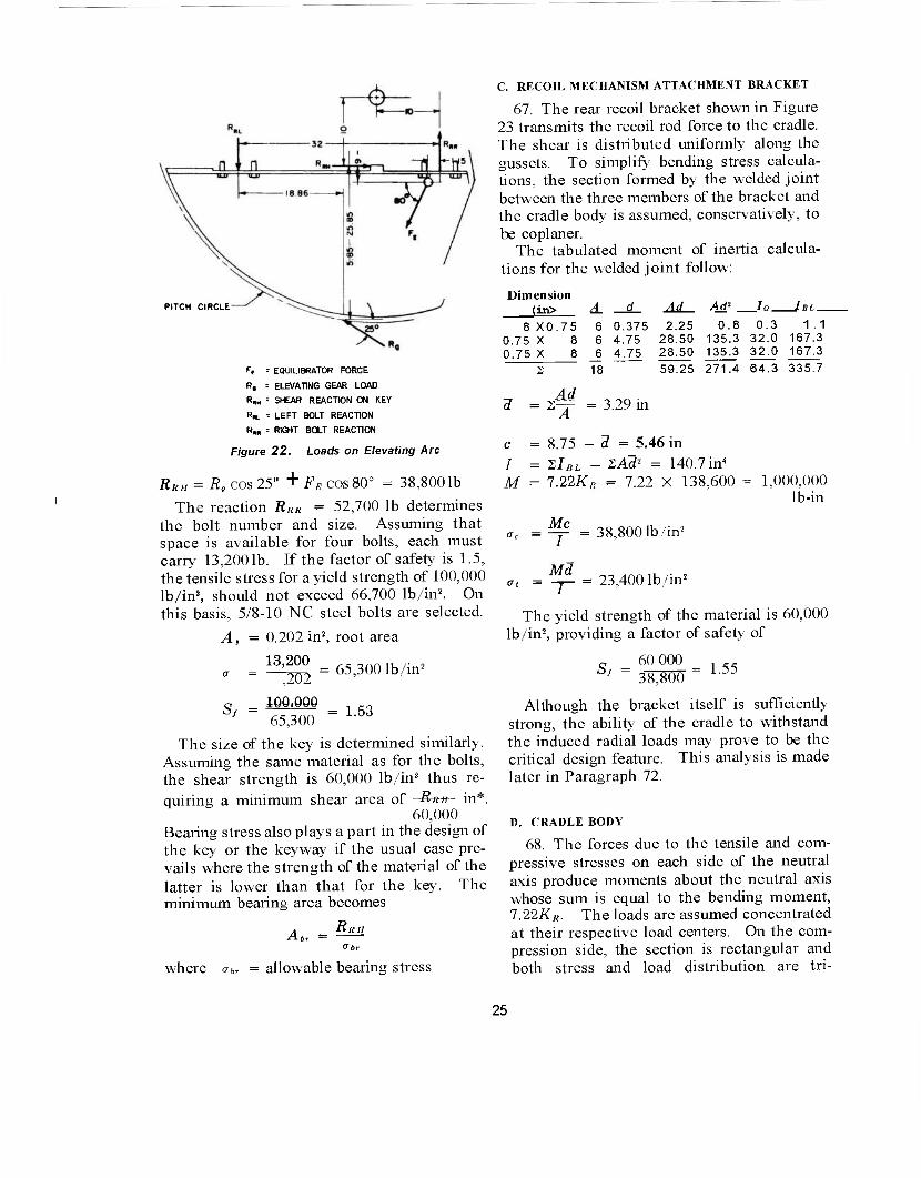
C. RECOIL MECHANISM ATTACHMENT BRACKET
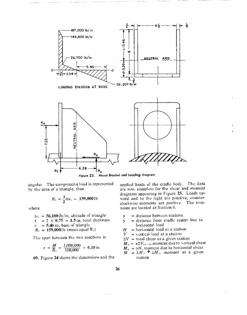
67. The rear recoil bracket shown in Figure 23 transmits the recoil rod force to the cradle. The shear is distributed uniformly along the gussets. To simplify bending stress calcula- tions, the section formed by the welded joint between the three members of the bracket and the cradle body is assumed, conservatively, to be coplaner.
The tabulated moment of inertia calcula- tions for the welded joint follow:
PITCH CIRCLE
Ff = EQUILIBRATOR FORCE
R, = ELEVATING GEAR LOAD
R„„ = SHEAR REACTION ON KEY
R«L = LEFT BOLT REACTION
Rw = RIGHT BOLT REACTION
Figure 22. Loads on Elevating Arc
RRlI = Rs cos 25" + FR cos 80° = 38,8001b
The reaction RiiH = 52,700 lb determines the bolt number and size. Assuming that space is available for four bolts, each must carry 13,2001b. If the factor of safety is 1.5, the tensile stress for a yield strength of 100,000 lb/in2, should not exceed 66,700 lb/in2. On this basis, 5/8-10 NC steel bolts are selected.
A, = 0.202 in2, root area
„ = ll^2 = 65,300 lb/in2
Sf - 65,300 = L53
The size of the key is determined similarly. Assuming the same material as for the bolts, the shear strength is 60,000 lb/in2 thus re-
quiring a minimum shear area of Run in*. 60,000
Bearing stress also plays a part in the design of the key or the keyway if the usual case pre- vails where the strength of the material of the latter is lower than that for the key. The minimum bearing area becomes
Run AbT =
Dimension (in> A d
8 X0.75 6 0.375 0.75 X 8 6 4.75 0.75 X 8 6 4.75
Ad Ad' In IRT
2.25 28.50 28.50
0.8 135.3 135.3
0.3 1.1 32.0 167.3 32.0 167.3
2 18 59.25 271.4 64.3 335.7
Ad 1 = 2~ = 3.29 in
A
c = 8.75 - d = 5.46 in
/ = XlBL - ZAd2 = = 140.7 in4
M = 1.22KR = 7.22 X 138,600 = = 1,000,000 lb-in
Mc ac =^Y = 38,800 It /in2
Md <jt = = 23,400 lb/in2
The yield strength of the material is 60,000 lb/in2, providing a factor of safety of
Sr = 60 000 38,800
= 1.55
Cjr
where abr = allowable bearing stress
Although the bracket itself is sufficiently strong, the ability of the cradle to withstand the induced radial loads may prove to be the critical design feature. This analysis is made later in Paragraph 72.
D. CRADLE BODY
68. The forces due to the tensile and com- pressive stresses on each side of the neutral axis produce moments about the neutral axis whose sum is equal to the bending moment, 7.22-K"«. The loads are assumed concentrated at their respective load centers. On the com- pression side, the section is rectangular and both stress and load distribution are tri-
25
fi / / / /
/
187,000 lb/in
H44.600 lb/in
26,700 lb/in
5.46
i-[-2.54-
J] 10
0> CM IO II T3
LOADING DIAGRAM AT BASE 58,200 lb/in
_UE1HRAL AXIS
3
F/gure 23. Reco/7 Bracket and Loading Diagram
angular. The compressive load is represented by the area of a triangle, thus,
Re = ~ct<rc 159,0001b
where
U, = 56,100 lb/in, altitude of triangle t = 2 X 0.75 = 1.5 in, total thickness c = 5.46 in, base of triangle Rt = 159,0001b (must equal R,)
The span between the two reactions is
M 1,000,000 c OQ. s = R, = 159,000 = 6-28in
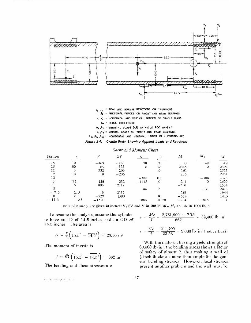
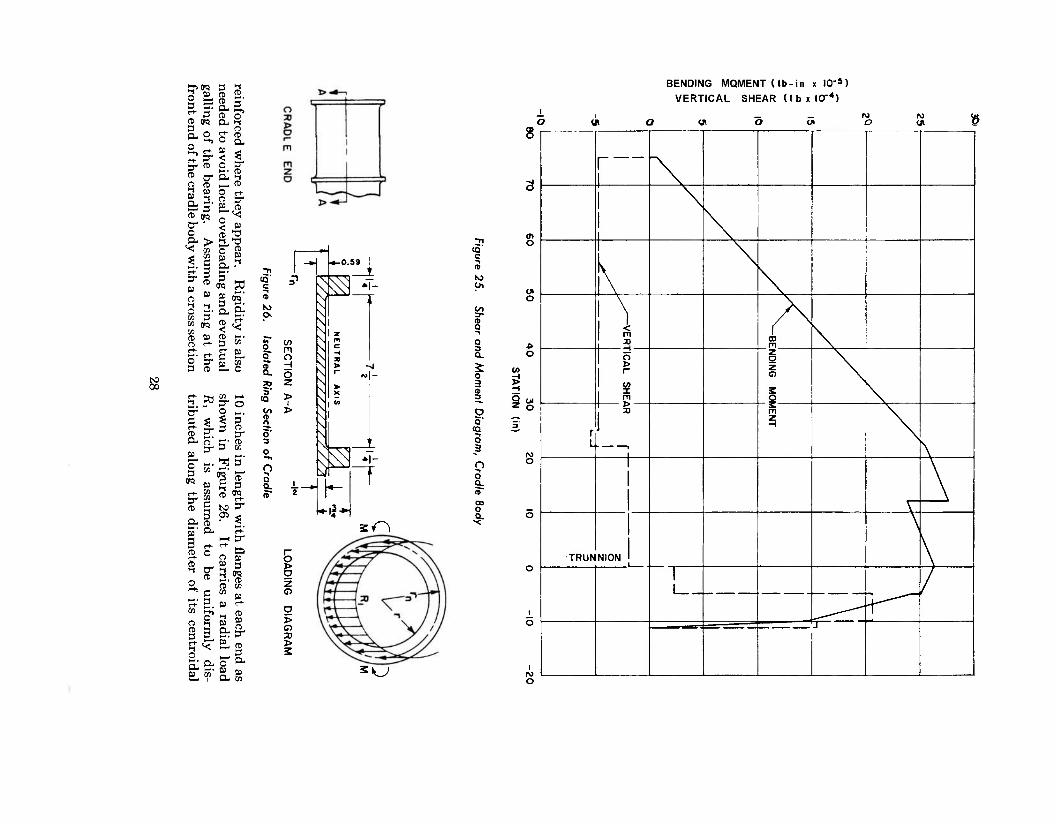
69. Figure 24 shows the dimensions and the
applied loads of the cradle body. The data are now complete for the shear and moment diagrams appearing in Figure 25. Loads up- ward and to the right are positive; counter- clockwise moments are positive. The trun- nions are located at Station 0.
x = distance between stations y = distance from cradle center line to
horizontal load H = horizontal load at a station V = vertical load at a station SV = total shear at a given station M, = *SV(,_i), moment due to vertical shear My = yH, moment due to horizontal shear M = 2M, + 2M„ moment at a given
station
26
\*sa--i- a.za-H
-&Z&Z&7777777J ¥ZZZZZZZZZZZZZZZZZZZZZZZZZZZZZZZZX££SäSäE&&
.J_L_
V7/A/A V////77777777/////^/////77T7T77M N.H
%L 52.0-
U»—lo.o-
Station
K F. AXIAL AND NORMAL REACTIONS ON TRUNNIONS
fi .Ji = FRCTIONAL FORCES ON FRONT AND REAR BEARINGS
H, ,VC = HORIZONTAL AND VERTICAL FORCES OF CRADLE MASS
K« = RECOIL ROD FORCE
Rc ,RT = VERTICAL LOADS DUE TO RECOIL ROD OFFSET
R, ,R2 = NORMAL LOADS ON FRONT AND REAR BEARINGS
RRH.R«..RS» " HORIZONTAL AND VERTICAL IjOAOS OF ELEVATING ARC
Figure 24. Cradle Body Showing Applied Loads and Reactions
Shear and Moment Chart
V 2V H Mr M»
Units of x andj' are given in inches; V, SV and H in 100 lb; Mx, Af„ and M in 1000 Ib-in
Mc 2,761,000 X 7.75 To resume the analysis, assume tho cylinder to have an ID of 14.5 inches and an OD a£ 15.5 inches. The area is
M
75 0 -469 -469 70 ? 0 49 49 25 50 -69 -538 6 0 2345 0 2394 22 3 332 -206 0 161 2555 12 10 0 -206 206 2961 12 -388 10 -388 2373 0 12 438 232 -1118 0 247 0 2620
— o 5 1885 2117 -116 2504 -5 44 7 -31 2473 - 7.5 2 5 0 2117 -529 1944 - 10 2 5 -527 1590 0 -529 1415 — 11.3 1 28 -1590 0 1386 8 78 -204 -1218 -7
662 32,400 lb in2
J(l5.5s - 14.5':) = 23.56 in' A 211,700
23.56 9,0001b in'2 (not critical)
The moment of inertia is
I = <Si M5.54 - 14J54) = 662 in4
The bending and shear stresses are
With the material having a yield strength of 60,000 lb in% the bending stress shows a factor of safety of almost 2, thus making a wall of ?i-inch thickness more than ample for the gen- eral bending stresses. However, local stresses present another problem and the wall must be
27
to
3 2- 3 C. «* 3 2 w S.S.
8 g sä Cj
£5' o- ' o ex >
*s
5» 3 3- 50 3 03 (jq S? . ft) 50 ft r+ rt- *-. e-t-
2 ^ 3 (5
3 3 ® 2. CD i-< a- g, CD cr CX i-( _^ ft o p^
2 ^ ►-. (D Cc if »— fD O rt- ft JT » CD
< £
IP Oq 50 to crS' CL, Cc
?£' CD M. 3 co r*- ci: C C- SL S
3 £°
CD 3"
» 0" o 3 TO
CD
CO (—i 3- O 0 Si 3 -1 ft
3- m 3 CO
*i 3
r CD 3
CD TO
CL (D
S - CD O
CO O
3
o &&: to co
NO 05
HH cr
3 'S >-;. CD CD CO
* » CO r+-
& cr 2- n>
3
6! JO Q. CO
c
K5
5' tQ
CO en n
3' 3
□ to. 5"
o w
BENDING MOMENT (lb-in x 10"»)
VERTICAL SHEAR (I b x ICT4)
«i o 8
8- 5
1 .
1 ■* -»-0.59 |
=' c ̂ *l- N' \
\ \ 1 \ | z
w s m m ^ o ^ H s > ->J o > > r N|- 2 ^ \ ? S > ^ \ J \
\ V \ " \ >^ *l- J t i
2 K- H**
SO
Tl 0) o
<Q c -t n> ►o C*
tit O
to 3-
8 "I
Q
1 o
£ 05 o H 3 5 3
o is Q
CQ 3
-i
Q =1
M
n O -i
a a. <s DO 0 _ a. o x
o > 2 z G5
O > C5 TO > 3
2«CJ
1
\
\
m CD m
1 > | r-
1 (/> . X
m
z o z o
5 o
,1 ■ L ,
s m z
1 1
TRUNNION 1
1 L_

(a) CHORDAL GUSSETS (b) TANGENTIAL GUSSETS
= 35,000 lb in-
Figure 27. Recoil Bracket With Gusset Reinforcement
axis. According to Equation 209 of Refer- ence 9*
M =gR,rn = g X 46,900 X 8.09 = 47,400lb-in
where r„ = r + .59 = 7.5 + 0.59 = 8.09 in, the radius to the neutral axis of the section
Mc
where I = 1.58 in4 c = 1.164 in
70. The two types of gusset construction discussed in Paragraph 51 are illustrated in Figure 27. Sketch (a) shows the gussets par- allel to chords of the ring. From Paragraph 68, the total load on two gussets is
Rc = 159,0001b
W = j Re = 79,500 lb, load per gusset
This condition is represented by Condition (d) of Paragraph 51 and Figure 21. The dimensions from Figures 23 and 27 are
a = 3.625 in 8 = 0.440 radian h = 7.22 in sin 8 = 0.426
Rm = 8.5 in cosö = 0.905
From Equation 34 "1
Mx = WR = (8 sin 8 T cos 0) - :
= 79,500 X 8.5 X (-0.152) = -102,800 lb-in
Reprinted by permission from Advanced Mechanics of Materials by B. F. Seely and J. O. Smith, Copyright 1952, John Wiley & Sons, Inc.
From Equation 35
Mu = WR Q 1
Ö- + - (e sin 8 -f cos e) Z7T 7T
sin f
68§Ji
= 79,500 X 8.5 X 0.139 = 94,000 lb-in
From Equation 36
5 1 Me= WR, [G COS20 COS 6
(> ?) = 79,500 X 8.5 X 0.177
From Equation 37
sin
119,700 lb-in
ADZ WR* El
- (8 sin 8 w
cos 8)
- j (sin'0
79,500 X 614 _ OU77 29 X 106/ X U1U3 ^~
+ 1)
in
From Equation 38
AD„ = WR4 El G-i)-(T-)™8
(2 1 . \ + I (- 2 sin Ö 1 co
79,500 X 614 _ 0175 29 X 106/ X ( UJU4 " /
in
71. Lower bending moments and deflections become available by having the gussets tangent to the ring as shown in Sketch (b) of Figure 27. Then, according to Paragraph 51 and Con- dition (c) of Figure 21, the bending moments and deflections are relieved despite the larger gusset load which increases by the ratio of d h, the distance of the applied load to the points of attachment of the two types of gusset. Thus
where
W = d X B- = 112,8001b h '- 2
d = 10.23 in h = 7.22 in
Other dimensions of Sketch (b), Figure 27, are
a = 3.625 in sin 8 = 0.954 R,,, = 8.25 in cos 0 = 0.300 e = 1.268 radian
29

From Equation 30
From Equation 31
From Equation 32
M,
M,, =
WR„, ~0 1 . ' K sin 0
7T Z
112.800 X 8.25 X < -0.074) =-- -68,800 lb-in
WR„, [C - 0 - [ - _ 1 J cos 0 "■" — sin 0 \7T / zV
112,800 X 8.25 X 0.038 -- 35,400 lb-in
iD, E^3
£7 2ö • „ , 6 — - sin 0 + - cos 0 T z
112,800 X 562 29 X 106 "
X 0.044 0.096
in
From Equation 33
AD, = El [(? - 0
112,800 X 562 29 X 10«/ (- ■ 0.037)= - j
sin e "•" cos 0
0.081 in
72. A comparison of the required wall thick- ness for the two conditions shows that the tangential gussets are preferred. For the chordal gussets, the maximum equivalent stress is at 6 (see Sketch (a) of Figure 27). The dimensions of the cradle wall at this loca- tion are
b = 5.46 in, assumed ring width (Figure 23) c = 8.78 in, chordal distance to gusset Ri = 7.5 in, inside radius ß„ =9.5 in, outside radius t = 2.0 in, wall thickness Me = 119,700 lb-in (see Paragraph 70)
Z = -bt2 = 3.64 in3, section modulus
cr, = -Me/Z = -32,800 lb/in2
/ = I (R* _ R*) = 3910 in4
The general bending moment is taken from the Shear and Moment Chart (Paragraph 69). At Station 5
a, = 38,4001b, in2, equivalent stress
60,000
17, — a;
Sr = -» 38,400
1.56, factor of safety.
For the tangential gussets, the maximum equivalent stress is located on the x-axis where the general bending stress is zero. Thus
\bV- 2.05 in:!
-AT. _ 33,500 lb /in'2
M = 2,473,000 lb-in
Mc _ 2,473,000 x -8.78 1 1 3910
From Equations 15a and 15b
5,600 lb in2
where Mx = -68,800 lb-in (see Paragraph 63) b = 5.46 in, assumed ring width (Figure 23) t = 1.5 in, wall thickness R„ =9.0 in, outer radius of cradle wall
The wall thickness of 1.5 inches is preferred over that of 2.0 inches, thus demonstrating the advantage of tangential gussets.
73. The bearing pressure induced by the gusset load is found according to the method discussed in Paragraph 52. By equating the expressions for ADy in Equation 39 and Para- graph 71, we have
1 U40/; EI El (-0.037)
30
so that the peripheral load is
0.043W _ 0.037 X 112,800 w 1080 1b in
0A67Rm 0.467 X 8.25
and from Equation 40, the induced bearing pressure is
1080 . Ph = b=5M =198PS1
The pressure is less than the limit stated in Paragraph 28.
Similarly, according to AD, in Paragraph 70, the bearing pressure induced by the chordal gusset load is
0.104W _ 0.104 X 79,500 . r* 0A67R„,L 0.467 X 8.5 X 5.46 " pS1
Although this pressure is greater than that for the tangential gussets, it is also less than the maximum allowable.
E. TRUNNION ANALYSIS
74. The trunnions support the normal and axial forces during firing plus the couple intro- duced by the rifling torque. From Equation 9
Tr = Q.6ir2RlP
N - - = 545,000 lb-in, rifling torque
where
Nr = 25 cal/turn, twist of rifling P9 = 36,000 psi, maximum propellant gas
pressure Rb = 4.0 in, radius of bore
FT = Tr
dt = 19,500 lb, trunnion load due to
torque
where
d, = 28 in, span of trunnion bearings
The maximum load on a trunnion bearing is
,500 lb
(see Paragraph 65 for values of FA and FN.)
75. The trunnion in the hub is shown in Figure 28. Assume triangular distributions for the reactions in the housing cylinder. Then, according to the dimensions shown
I = X 2.76" = 2.85 in4
64
r •H
^£Ü nflii !^- CENTERS -
-1.666 *1 OF
i REACTIONS
ill
A ) I
3 RAO
Figure 28. Trunnion Loads and Reactions
56,300 lb-in2
M = 1.66F,- = 116,000 lb-in
Mc _ 116,000 X 1.38 " ~ I 2.85
The trunnion is made of steel with a yield strength of 90,000 lb in'
c 90,000 Sf = 56^00 = L6°
This is a short beam, therefore, the horizontal shear stress may be severe
_ FTAy It
14,5001b in"
Sf = 0.6 X 90,000
15,500 = 3.48 (not critical)
A | X J X 2.762 = 2.99 in"
t = 2.76 in y = 0.586 in
76. The trunnion housing shown ,n Figure 19 is a weldment. The principal stresses occur in the welds of the gussets and in the joint between hub and cradle body. Four gussets on each housing are parallel to the cradle axis and carry components of the axial force F,. Four other gussets on each housing are perpen- dicular to the axis and carry components of the normal forces FR and F„. The analysis cf the former will be shown. Figure 29 shows the isolated gusset with the applied loads.
The numerical values of Figure 19 are
a = 4.7 in n = 4, number of gussets c = 3.45 r» = 2.75
F, = 111,8001b (see Paragraph 65)
-012 (8040A) O - 67 - . 31
3.96 •
Figure 29. Gusset load Diagram
According to Equation 17, R0 = 28,000 lb, the total horizontal load on each gusset. From Equations 17b and 17e
Rh = R = (a - 3 O EA = 2.4 X 111,800 n n 2.75 X 4
= 24,400 lb
the vertical load and reaction on the gusset. According to Equation 18,
2 X 28,000 .,„„„,,, w = ^-JJ = 16,2001b, in, maximum
linear load
For a thickness of t =0.5 in, the direct tensile or compressive stress between gusset and hub is
w a = — = 32,4604b ./in2 (seeEquation 19)
The direct shear stress is
24,400 RH
0.5c 0.5 X 3.45
The combined shear stress is
= 14,1001b/in2
an" w = ijuj + r2 = 21,500 lb/ir
The combined tensile or compressive stress is
<w = \ + rMI = 37,700 lb/in2
With a tensile yield strength of 60,000 lb/in2, the shear and tensile factors of safety are, respectively,
„ _ .6 X 60,000 _ ^ - 21,500 " llb/
CRADLE BODY
WELD
(b) TANGENTIAL GUSSETS
Figure 30. Trunnion Housing With Gusset Reinforcement
sf 60,000 37,700
From Equation 17f
b = —n— 2-75
= 1.59
c° 2.4 X 3.45 = 3.96 in
the required gusset length for the attachment to the cradle body. The stresses here are obviously less than those between gusset and trunnion hub.
77. The effects of the gussets on the cradle wall are discussed in Paragraph 50. In Figure 29, R, represents the load W of Condition (b), Paragraph 50, and the chordal gussets in Figure 30a.
a = 2 in e = 0.237 radian h = 3.45 in sin e = 0.235 R„, = 8.5 in cose = 0.972
32

From Equation 25
Mx = WR,\ sin e T cos 0) 1 1 = 24,406-X 8.5 X (-0.346) = -71,700 lb-in
From Equation 26
M» = WR, sin e "■" cos 0) — sin e
24,400 X 8.5 X 0.419 = 87,000 lb-in
From Equation 28
ADZ =
From Equation 29
AD, =
WR,
[* EI
24.400 X 614 29 X 10°/
(0 sin e "•" cos 0) sin-0
(0.253) 0.131 .
in
wn: EI
24,400 X 614
- (0 sin e + cos 0) + (cose - 2) sin 0 + ( 0 - ^ )
-0.268) 0.139.
29 X 106 I
78. When the gussets are made tangent to the cradle body at the mean radius as shown in Figure 30b, they tend to develop smaller bending moments and deflections. The load Wincreases over the above value by the ratio of d 'Mbr the reason presented in Paragraph 71.
in
Afl, WRt, T40 EI\.
44,900 X 562 29 X 106
From Equation 24
cos 0
X 0.127
2 sin e
0.1108 /
W = r 24,400 h
where d = 6.35 in h = 3.45 in
Other dimensions are
a = 2 in Rm = 8.25 in e = 1.033 radian
44,900 lb AD,= WR ;[(" EI [_\ir 44,900 X 562
29 X 108/
2J+ 2cos0 +(e -|js
(-0.122)
sin<
-0.1062 in
sin e = 0.859 cos0 = 0.512
From Equation 21
Mx =WRmV^- - sine]
= 44,900 X 8.25 ( -0.201) = -74,5001b-in
From Equation 22
My = WRm \~ + (cos 0 - 1)1
= 44,900 X 8.25 X .170 = 63,000 lb-in
From Equation 23
A comparison of results obtained for the two types of gussets shows that, although the tangential type has almost twice the load, the bending moments and deflections produced in the cradle wall are less than the maximum corresponding values of the parallel gussets.
79. To compute the induced bearing pres- sure, the procedure used in Paragraph 73 is followed
- *^f (-0.122)
0.122 X 44,900
(-0.467)^/
0.467 X 8.25 = 1,4221b in, peripheral
load
From Equation 40, the bearing pressure is
p _ w _ 1422 b b 3.96
= 360 psi
33

where b = 3.96 in (see Figure 29, Paragraph 76).
The pressure meets the conditions stated in Paragraph 28.
80. The critical compressive stress obtained from Equation 20 indicates that the possibility of the gussets buckling is extremely remote.
therefore
- = K- r^(!i)2 = 540' where a = 3.96 in
b = 3.45 in E = 29 X 106 lb in-
000 lb in-
K. = 1.06 t = 0.5 in T = 0.3
VII. SAMPLE PROBLEM, U-TYPE CRADLE
A. LOAD ANALYSIS
81. A U-type cradle is selected for the sample problem involving a single recoil gun crrriage. Figure 5a represents the loading diagram for the analysis
a = 80 in d = 0.1 in b = 20 in e = 8 in c=16in h = 7 in
W, = 10,0001b, weight of recoiling parts F„ = 1,810,0001b, propellant gas force K = 150,0001b, total recoil resistance n =0.15, coefficient of friction e = 60°, angle of elevation
82. The values of Ri, R2, f\, U and KK are unknown. These are found by balancing the loads and moments.
From Equation 3, since i*\ is zero, the inertia force is
F„ = F0 + Wi sin e - K = 1,810,000 + 8700 - 150,000
= 1,668,7001b 2V = 0 R, - R2 + W cos e = 0 R2 = AL + 5000
ZH = 0 From Equation 2
KR +// +/, -K = 0
but from Equations 1 and la
/, = ßR, = 0.15Ä1 /, = ßR2 = 0.15 (Ä, + 5000)
(A + 12) 149,200 - 0.30Ä, KR = K ^M„; = 0
(c-e)Klt +eF, _ (e-d^Fa - Wsint) - aW cos e - (e-h)f! - (a-b)R, = 0
(a-bjR, = 60ß, (e-h)fi = 1.0(0.15«!) = 0.15Ä1 (c-e)Klt = 8(149,200 - 0.30 R,J
= 1,194,000 - 2.40Ä! eFg = 8 X 1,810,000 = 14,480,000 (e-d){Fa - Wsin8) = 7.9 X 1,660,000
= 13,114,000 aW cos e = 80 X 5000 = 400,000
62.55Ä, = 2,160,000 R, = 34,500 1b R, = 39,500 1b U = 52001b h = 59001b Klt = 138,9001b
1. Rails and Slides
83. The reactions R\ and fi2 are carried equally by two rails, each 90 inches long. These reactions have an assumed triangular distribution, but the reaction due to rifling torque is distributed uniformly. The rails are 3.0 inches wide and their center-to-center distance is 17 inches. From Paragraph 74, Tr = 545,000 lb-in
T
wr = EL 90
545,000 17
= 355 lb in
32,000 lb
Let ^R'2 represent the triangular portion of R'2 (see Figure 12).
m wo = - Rt
39,5.00 „„^,, ,. u>n = 45 = 875 lb /in
w = W'2 ' wr = 1230 lb/in
The maximum bearing pressure becomes
<rbr = J = 410 lb/in2
This pressure is acceptable according to Paragraph 28.
34
The strength of the rail or slide is determined according to Paragraph 32 and Figure 17. Assume that rail and slide have identical cross- sectional dimensions
= b = 0.75 in = e = 2.25 in = 1.0«; = 12301b = 1.0 X 0.75 = 0.75 in' II
~ c ~ 6 = eF = 2770 lb-in
From Equation 11
~ +~ -29,600 + 1600= 31,2001b in' Z A
60,000
a d F A
Z
M
X 1.0 X 0.75"= 0.0937 in'
O I
Sf 31,200 = 1.92
2. Equilibrator Load
84. Calculate the equilibrator force, FK, by balancing the weight moment of the tipping parts about the trunnions. Referring to Figure 8
M„ = rtWv cos [8 + <M t r,W, cos (6 + <h) = 461,000 lb-in
where
ri - 75 in 0 = 60°, angle of eleva r, = 25 in 0, = 0°04' W, = 10,0001b <t>2 -= -30° Wc = 4000 lb
The equilibrator force is found by eq; ii the equilibrator moment to the weigh ment.
rFh: = Mw = 461,000 lb-in
when r = 12 in
F,, =■ 38,400 lb, equilibrator fon;?
85. The equilibrator attachment »/ cradle is similar to the trunnion housi i Figure 31. Its location is designated > force diagram of Figures 8 and 32. The c on the primary cradle structure are
3.91 R
R<
12 Fh cos (0 - \ i -t ? Ff sin i
^y X 37,200 + |x 10,000 = 17
3^91 12
= 12,100
F,; cos (e -
5000
F,, sin (0
■ ne
of
7100 lb
HOUSING-
TRUNNION
TRUNNION HOUSING
'"'^-r
CRADLE >■
Figure 31. Trunnion Housing and Cross Section of Cradle
35

t TRUNNION iRt
figure 32. Applied Loads on Cradle
RE = FKCOS (e - X) = 37,2001b
where A = 45" (see Paragraph 86).
3. Elevating Gear Load
86. The reaction on the elevating gear arc, R0, is found by balancing the moment about the trunnions. Additional dimensions for Figure 8 are:
A = 45" 7 = 50°
a = 0.10 in b = 0.2 in
ß = 20°, pressure angle of gear tooth R, = 36 in, pitch radius of elevating arc
87. With reference to Figures 8 and 33, the loads at the attachments of elevating arc to cradle are calculated by resolving the gear tooth load about these attachments. Take moments about the intersection of Rim and Rnu, the shear reaction on the key, and solve for Rui .
20R,t!. = 4.3R„ cos (8 + P + y) + UR„ sin (0 + ß + y)
= 4.3 X 3700 + 14 X 4400 = 77,500 Rm. = 3900 1b Run = RRL + R„ cos (d + ß + y) = 7600 lb RH„ = Ru sin (e + ß + 7) = 4400 lb
36

the above loads are determined as shown in Paragraph 66.
4. Trunnion Loads
88. The trunnion reactions, FA and F,v, are found by summation of forces parallel and perpendicular to the center line of the bore (Figure 8).
F.v = FE sin (e - A) + R„ cos (8 + ß + y) — Wl cos 8 — Wc cos 4>-i
= 10,000 + 3700 - 5000 - 3500 = 5,200 lb
F„ = F„ - Fa + Wi sin e + W, sin <fe + FB cos (6 - A) + Ä„ sin (fl + 0 + y)
= 1,810,000 - 1,668,700 + 8700 + 2000 + 37,200 + 4400 = 193,6001b
89. The maximum load on the trunnion housing bolts is applied when the rifling torque is maximum.
Tr = 545,000 lb-in (seeParagraph 74)
F"r ^^-^9,400 lb 1
Fy _ 5200 2 ~ 2 ~
FA 193,600
2600 lb
= 96,800 lb
With reference to Figure 31, the maximum bolt load is
ä; 5,8 F, 18 A 2
= 31,200 + 13,400 = 44,6001b
There are four 5 18-1 INC bolts at R,
A = 4 X 0.202 = 0.808 in2, total root area
<J = -T- = 55,300 lb in2, tensile stress
b/ - ^300 - L81
R, = ^ = 96,800 lb, key load
A, = 4.5 X 0.75 = 3.375 in2, shear area
R. r =A.
28,700 lb/in2, shear stress
S, = 0.6 X 100,000 2.09
28,700
Ahr = 4.5 X 0.375 = 1.6875in2, bearing area
R. Ahr
— 57,400 lb in2, bearing stress
The cradle material has the lesser strength. At a yield of 60,000 lb in2
S, = 1.4 X 60,000
57,400 1.46
90. The trunnion bearings are based on the loads that are present when the rifling torque is maximum. This is the only condition to be investigated here. Other conditions may be more critical and should be checked. From Paragraph 74
FT = 19,5001b
From Paragraph 88
F.v FA
5200 lb 193,600 lb
Maximum trunnion load
*> - ww- *y - 100,0001b
The trunnion bearing load of the single recoil type is over 45 per cent more than that for the double recoil type illustrating one ad- vantage of having the latter type system (see Paragraph 74). The remaining analyses of trunnion and hub follow procedures similar to those of Paragraphs 74 through 76.
91. The reactions producedl by the rifling torque are transmitted directly from the slides to the trunnion housing and therefore do not enter into the analysis of the (U-shaped) primary cradle structure. All the remaining normal and axial loads and reactions are con- sidered. With reference to Figures 31 and 32, the total reactions now become
R, = ~~FA - JF.V = 62,400 - 2600 = 59,800
R, =J§FA +^F.v = 65,0001b
R. = F, = 193,6001b
37
B. CRADLE BODY
1. Shear and Moment Chart
Station V XV H Mx M, M
59.35 0 171 171 0 0 0 0 0 55.00 4.35 345 516
52 6.35 -74
-33 -74
-107 53.35 1 .65 0 516
372 7.35 -85
-273 -192 -465
47.35 6.00 -71 445 0 0 -310 0 -775 21.65 25.70 -35 410
20 65 -1143
-1 -1918 -1919
12 9.65 -39 371 0 0 -396 0 -2315 9 3.00 -650 -279 0 0 -111 0 -2426 2 7.00 0 -279
44 6.65 195
29 -2231 -2202
0 2.00 0 -279 -1936 7.35
56 1420
-2146 -726
5 5.00 -395 -674 59 5.35
139 -32
-587 -619
8 3.00 76 -598 0 0 202 -417 9 1.00 598 0 0 0 60 -357 15 6.00 0 0 1389 2.65 368 + 11
Units of x andy are given in inches; V, SV and/f in 1001b; M„, M, and M in 1000 lb-in. The maximum bending moment occurs nine inches in front of the trunnion. The moment of inertia is based on
the dimension of the cradle cross section shown in Figure 31.
2. Sti"ess and Deflection
92. The bending stress of 10,200 lb in2
falls far below the stress that would yield a factor of safety of 1.5. However, rigidity is a property of higher priority inasmuch as large deflections eventually mean poor accuracy Thus, rather than decrease the section and in- crease its structural efficiency stress-wise, it is better to maintain its rigidity to promote better accuracy. Both structures, cradle and gun tube, combine their stiffness although they are treated as two parallel beams with no hori- zontal shear connection between them.
93. The deflections are determined by the moment area method (refer to Figure 34). First, the deflection is determined for the structu■■* ■ at the breech end by computing the moment of the M El area at this point, Station -15.0. This deflection is normal to the tangent of the elastic line at Station 59.35. Referring to the Shear and Moment Chart of Paragraph 91, the value of M I is computed for eacn station and drawn to scale in Figure 34.
I = I, + IT = 4600 in'
Dimension (in> A
198
d.
5.5
Ad
1090
Ad'
5995
Io
18 X 11 1996 16 X 10 -160 6.0 -960 -5760 -1333 9x3 27 12.5 337.5 4219 20 6X1 -6 12.5 -75 -938 -
2 59 392.5 3516 683
The moment of inertia at the base line (BL) is
IHI. = 2Ad'! + S/o = 4200 in4
— 2 Ad d = "„ -A = 6.65 in, distance from base line to
neutral axis ZA
/,. = IB, _ zAd- = 1590 in4, moment of inertia of cradle section
c = 14 - d = 7.35 in
= Mc _ 2,426,000 X 7.35 = 11,200 lb in2, a I 1590 bending stress
In the above table Dimension = base X height of parts of the
section
A = area of each part d = distance from base line to neu-
tral axis of part
38
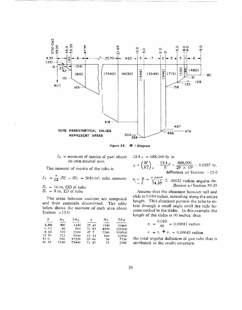
CO z o - If)
IT) O ro ifl
fO If) fO r-
CO f> :n if) Tf
NOTE: PARENTHETICAL VALUES
REPRESENT AREAS
Figure 34. M I Diagram
Io = moment of inertia of part about its own neutral axis
The moment of inertia of the tube is
Ir =
16 in, OD of tube 8 in, ID of tube
The areas between stations are computed and their centroids determined. The table below shows the moment of each area about Station —15.0.
AM xA» AM xA u
3.00 480 1440 25 49 1548 39400 6.51 86 560 31 83 4030 128200 8 60 339 2910 47 7 7540 359500 12 59 715 9000 65 11 810 52750 16 0 946 15200 69 06 54 3730 20 55 3549 73000 71 45 35 2500
ZxA u = 688,000 lb in
ZxA,, 688,000 w« OT {D* - DV) = 3010 in4, tube moment e
_4 0.0Ü0 7
1 - L 74.35
E - 29 X IO«" °0237 in' deflection at Station - 15.0
.00032 radian angular de- flection a.t Station 59.35
Assume that the clearance between rail and slide is 0.010 inches, extending along the entire length. This clearance permits the tube to ro- tate through a small angle until the rails be- come cocked in the slides. In this example, the length of the slides is 90 inches, thus
0.010 ».. = 90 "
= tix + 6;
0.00011 radian
0.00043 radian
the total angular deflection of gun tube that is attributed to the cradle structure.
39
GLOSSARY
breechblock. The part of a gun, especially a cannon, which closes the breech.
carriage, gun. Mobile or fixed support for a cannon.
carriage, top. Primary supporting structure of a weapon. It supports the tipping parts and moves with the cradle in traverse. In double recoil systems it comprises the bulk of the secondary recoiling mass.
clip. A component of a discontinuous guide. counterrecoil. Forward movement of a gun
returning to firing position (battery) after recoil.
cradle. The nonrecoiling structure of a weapon which houses the recoiling parts and rotates about the trunnions to elevate the weapon.
cradle, O-type. A cradle which supports the gun tube within a cylindrical housing.
cradle, U-type. A cradle which supports the gun tube on longitudinal guides.
elevating arc. A gear segment rigidly at- tached to the tipping parts and serving as the terminal member in the gear train of the elevating mechanism.
elevating mechanism. Mechanism on a gun carriage or launcher by which the tip- ping parts are elevated or depressed.
elevation. Angle of elevation; the process of changing the angle of elevation.
equilibrator. The force-producing mechan- ism whose function is to provide a moment about the cradle trunnions equal and op- posite to that caused by the muzzle prepon- derance of the tipping parts, thereby re- ducing the effort required to elevate.
force, equilibrator. The force generated by the equilibrator.
force, propellant gas. The force due to the propellant gases that drives the gun rear- ward into recoil.
force, recoil. The resistance provided to the recoiling parts.
guide. Channel-shaped structure of the cradle which provides sliding surface and
support to the recoiling parts during the re- coil cycle.
guide, continuous. Guide made of one con- tinuous member.
guide, discontinuous. Guide made of sev- eral short lengths spaced at regular inter- vals. See clip.
lug, gun. An appendage of the breech ring for attaching the recoil mechanism.
moment, tipping. The couple created by the firing forces and the inertia of the tip- ping parts.
moment, upsetting. The couple created by the firing forces and the inertia of the re- coiling parts.
moment, weight. The moment about the cradle trunnions produced by the weight of the tipping parts.
mount, gun. An item designed to support a gun.
rail. A supporting member of the recoiling parts that slides in a guide.
rail, continuous. Rail made of one member. rail, discontinuous. Rail made of several
short lengths spaced at regular intervals. recoil. The rearward movement of a gun
caused by the propellant gas force. recoil cylinder. The cylinder that houses the
recoil brake. recoil mechanism. The unit that absorbs
some of the energy of recoil and stores the rest for returning the recoiling parts to battery.
recoil mechanism, concentric. A recoil mechanism that is assembled concentrically on the gun tube.
recoil system, double. A system in which the gun recoils on the top carriage and the top carriage recoils on the bottom carriage.
recoil system, single. A system that has only the gun tube and its components as recoiling parts.
recoiling parts. Those parts of a weapon that move in recoil.
recoiling parts, primary. In a double recoil
40

system, the recoiling parts equivalent to those of a single recoil system, i.e., tube, breech assembly, guides or sleigh, and those parts of the recoil mechanism which move with the tube.
recoiling parts, secondary. In a double recoil system, the cradle, those parts of the primary recoil mechanism which do not move with the tube, the top carriage, and all those parts attached to it.
recuperator. The equipment that stores some of the energy of recoil for counterre- coil.
ring, breech. Breechblock housing, screwed or shrunk on the rear of a cannon.
sleigh. The housing of a gun tube that slides in a U-type cradle during the recoil cycle.
slide. Same as rail. tipping parts. The assembled structure of a
weapon which moves in elevation or de- pression about the trunnions.
torque, rifling. The reaction on the gun tube of the angular accelerating forces on the projectile.
traversing gear. A gear rigidly attached to the traversing parts and meshed with the traversing mechanism.
trunnion. The cylindrical structural com- ponent of the cradle which serves as the pivot for the tipping parts and which trans- mits the recoil forces to the top carriage.
trunnion bearing. The bearing that sup- ports the trunnion.
tube, gun. A hollow cylinder, usually of steel, in which a round of ammunition is fired and directed.
tube whip. The flexing of the gun tube due to accelerating forces normal to the tube axis.
41

REFERENCES
ORDP 20-340, Ordnance Engineering Design Handbook, Carriages and Mounts Series, Car- riages and Mounts, General. ORDP 20-342, Ordnance Engineering Design Handbook, Carriages and Mounts Series, Recoil Systems. ORDP 20-345, Ordnance Engineering Design Handbook, Carriages and Mounts Series, Equi- librators. A Report on the Analysis of Gun Carriage, 175mm, T76, The Franklin Institute, Final Report F-2240, Part I. Charles D. Hodgman, et al, Ed., Handbook of
Chemistry and Physics,. 40th Ed., Chemical Rub- ber Publishing Company, Cleveland, 1958-1959.
6. Hoffman and Sachs, Introduction to the Theory of Plasticity for Engineers, McGraw-Hill Book Co., Inc., New York, 1953.
7. R. J. Roark, Formulas for Stress and Strain, 3rd Ed., McGraw-Hill Book Co., Inc., New York, 1954.
8. ORDP 20-134, Ordnance Engineering Design Handbook, Maintenance Engineering Principles for Design Engineers.
9. F. B. Seely and J. O. Smith, Advanced Mechanics of Materials, John Wiley and Sons, Inc., New York, 1952.
42
INDEX
Cleaning, 22 Cradle
body, 25, 37 see also Structure function of, 1 0-type, 3, 10, 23 type, 2 U-type, 2, 10,34
Design of trunnion, 16,31 practice, 21 problem, 23, 24 procedure, 5
Elevating arc, 2, 7, 24, 36 Equilibrator, 2, 7 Equilibrator force, 7, 24, 35
Friction effect, 15
Glossary, 40 Gussets, 18,29, 32,34
Illustrations, list, v Inspection, 22
Keys, 24
Load a'nalysis, 23, 34 Lubrication, 22
Maintenance, 22 Manufacture, 22 Materials, 22
0-type cradle, 3, 10,23
Rails, 13,34 Recoil
attachment bracket, 20, 25 force, 5 mechanism, 1,5
References, 42 Rifling torque, 10, 31
Sample problem, 23, 34 Shear and moment chart, 26, 37 Sleigh, 2, 13 Sliding surfaces, 11,15, 34 Strength requirement, 17 Structure, 5, 21 see also Cradle body Symbols, list, vi
Temperature effect, 4 Trunnion, 2, 16, 18,24, 31, 37
analysis, 31 design, 16, 31 hub, 18 load, 16,24,57 location. 16
U-type cradle, 2, 10, 34
43
U. S. GOVERNMENT PRINTING OKI.'iCE . 1967 O- 255-012 (H040A)
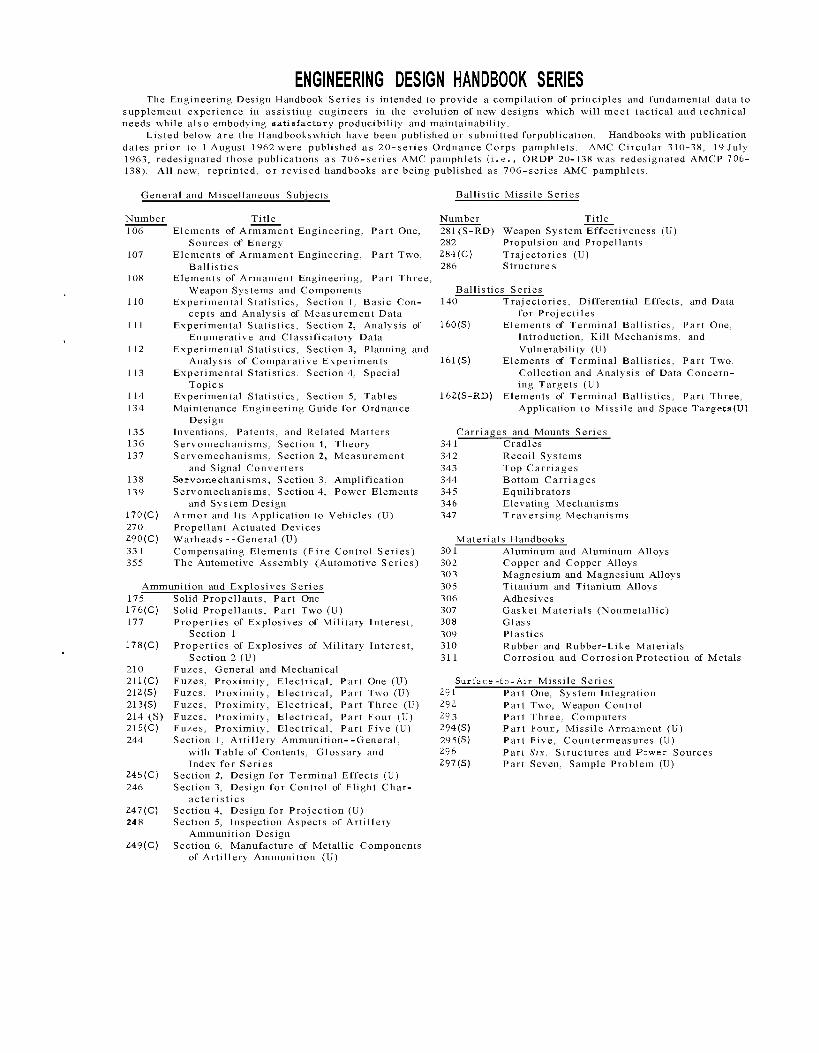
ENGINEERING DESIGN HANDBOOK SERIES The Engineering Design Handbook Series is intended to provide a compilation of principles and fundamental data to
supplement experience in assisting engineers in the evolution of new designs which will meet tactical and technical needs while also embodying satisfactory producibility and maintainability.
Listed below are the Handbookswhich have been published or submitted forpublication. Handbooks with publication dates prior to 1 August 1962 were published as 20-series Ordnance Corps pamphlets. AMC Circular 310-38, 19 July 1963, redesignated those publications as 706-series AMC pamphlets (i.e., ORDP 20-138 was redesignated AMCP 706- 138). All new, reprinted, or revised handbooks are being published as 706-series AMC pamphlets.
General and Miscellaneous Subjects Ballistic Missile Series
Number Title 106 Elements of Armament Engineering, Part One,
Sources of Energy 107 Elements of Armament Engineering, Part Two,
Ballistics 108 Elements of Armament Engineering, Part Three,
Weapon Systems and Components 110 Experimental Statistics, Section 1, Basic Con-
cepts and Analysis of Measurement Data 111 Experimental Statistics, Section 2, Analysis of
Enumerative and Classificatory Data 112 Experimental Statistics, Section 3, Planning and
Analysis of Comparative Experiments 113 Experimental Statistics. Section 4, Special
Topics 114 Experimental Statistics, Section 5, Tables 134 Maintenance Engineering Guide for Ordnance
Design 135 Inventions, Patents, and Related Matters 136 Servomechanisms, Section 1, Theory 137 Servomechanisms, Section 2, Measurement
and Signal Converters 138 Servomechanisms, Section 3, Amplification 139 Servomechanisms, Section 4, Power Elements
and System Design 170(C) Armor and Its Application to Vehicles (U) 270 Propellant Actuated Devices 290(C) Warheads --General (U) 331 Compensating Elements (Fire Control Series) 355 The Automotive Assembly (Automotive Series)
Ammunition and Explosives Series 175 Solid Propellants, Part One 176(C) Solid Propellants, Part Two (U) 177 Properties of Explosives of Military Interest,
Section 1 178(C) Properties of Explosives of Military Interest,
Section 2 (U) 210 Fuzes, General and Mechanical 211(C) Fuzes, Proximity, Electrical, Part One (U) 212(S) Fuzes, Proximity, Electrical, Part Two (U) 213(S) Fuzes, Proximity, Electrical, Part Three (U) 214 (S) Fuzes, Proximity, Electrical, Part Four (U) 215(C) Fuzes, Proximity, Electrical, Part Five (U) 244 Section 1, Artillery Ammunition--General,
with Table of Contents, Glossary and Index for Series
245(C) Section 2, Design for Terminal Effects (U) 246 Section 3, Design for Control of Flight Char-
acteristics 247(C) Section 4, Design for Projection (U) 248 Section 5, Inspection Aspects of Artillery
Ammunition Design 249(C) Section 6, Manufacture of Metallic Components
of Artillery Ammunition (U)
Number Title 281(S-RD) Weapon System Effectiveness (U) 282 Propulsion and Propellants 284(C) Trajectories (U) 286 Structures
Ballistics Series 140 Trajectories, Differential Effects, and Data
for Projectiles 160(S) Elements of Terminal Ballistics, Part One,
Introduction, Kill Mechanisms, and Vulnerability (U)
161(S) Elements of Terminal Ballistics, Part Two, Collection and Analysis of Data Concern- ing Targets (U)
162(S-RD) Elements of Terminal Ballistics, Part Three, Application to Missile and Space Targets(U)
Carriages and Mounts Series 341 Cradles 342 Recoil Systems 343 Top Carriages 344 Bottom Carriages 345 Equilibrators 346 Elevating Mechanisms 347 Traversing Mechanisms
Materials Handbooks 301 Aluminum and Aluminum Alloys 302 Copper and Copper Alloys 303 Magnesium and Magnesium Alloys 305 Titanium and Titanium Alloys 306 Adhesives 307 Gasket Materials (Nonmetallic) 308 Glass 309 Plastics 310 Rubber and Rubber-Like Materials 311 Corrosion and Corrosion Protection of Metals
Surface -to-Air Missile Series 291 Part One, System Integration 292 Part Two, Weapon Control 29 3 Part Three, Computers 294(S) Part Four, Missile Armament (U) 295(S) Part Five, Countermeasures (U) 296 Part Six, Structures and Pawer Sources 297(S) Part Seven, Sample Problem (U)