resea ch report uktrp 83-21 for rigid & flexible conduit
TRANSCRIPT

Resea�ch Report UKTRP - 83-21
STRUCTURAL D ESIGN AND INSTALLATION CRITERIA FOR RIGID &� FLEXIBLE COND UIT
by
Ronald D. Hughes Deputy Director
Kentucky Transportation Research Program College of Engineering University of Kentucky
in cooperation w�th Transportation Cabinet
Commonwealth of Kentucky
and
Federal Highway Administration U.S. Department of Transportation
The contents of this report reflect the views of the author who is responsible for the facts and the accuracy of the data presented herein. The contents do not necessarily reflect the official views or policies of the University of Kentucky,
of the Federal Highway Administration, or the Kentucky Transportation Cabinet. This
report does not constitute a standard, specification, or regulation.
September 1983

Technical Report Documentation Page 1. Report No. 2. Government Accession No. 3. Recipient's Catalog No.
4. Title and Subtitle 5. Report Dote
Structural Design and Installation Criteria September 1983
for Rigid and Flexible Conduit 6. Performing Orgonizotion Code
8. Performing Orgoni::otion Report No, 7, Author( s)
Ronald D. Hughes UKTRP-83-21
9, Performing Organization Nome and Address 10. Work Unit No. (TRAlS)
Transportation Research Program College of Engineering 11. Contract or Grant No.
University of Kentucky KYHPR-84-103
T.PxinPron Kentuckv 40506-0043 13. Type of Report end Period Cove.red
12. Sponsoring Agency Nome and Address
Kentucky Transportation Cabinet Interim
State Office Building Frankfort, Kentucky 40622 14. Sponsoring Agency Code
15. Supplementary Notes Prepared in cooperation with the u. s. Department of
. Transportat�on, �·ectera.L li�ghway 8.am�n�s c >n. . Study Title: Fill-Height Tables for Pipe, Pipe-arch, and Arch Culverts
16. Abstract
Structural design criteria according to current AASHTO guidelines for pipe, pipe-arch,
and arch culverts are presented. Fill-height tables, based upon fhose criteria, and
proposed bedding details are included.
17. Key Words 18. Distribution Statement Culvert bedding Pipe Structural design Pipe-arch Installation Arch Fill Height
19. Security Clossif. (of this report) 20. Security Clossif. (of this page) 21. No, of Pages 22. Price
Unclassified Unclassified
Form DOT F 1700.7 IB-72l Reproduction of completed page authorized

EXECUTIVE Su'NMARY
Significant percentages of highway construction and maintenance funds are expended on install ation, maintenance, and restoration of drainage structures. On the average, cast- in-place reinforced concrete box cul verts cost about twice as much as comparable rigid or flexible pipe, pipearch, and arch structures. Provisions for only limited use of box culverts should prove to be economically advantageous.
structure interaction design criteria, would prov de for -----�----�-mere e><tenH'!e use of fl exi bl e pipe and pipe arches and
rigid pipe and arches. Current state-of-the-art design methodologies for both soil-reinforced concrete structure interaction systems and soil-corrugated metal structure interaction systems are presented in this report.
Proposed fill-height tables, based upon current AASHTO design criteria, are presented in Appendix A and Appendix B, respectively, for flexible and rigid conduit. Separate bedding details for rigid and flexible conduit are proposed in Appendix c. Current camber design guidelines are presented in Appendix D.
INTRODUCTION
An average of 25 p_ercent of all highway constructi.on funds are expended for drainage structures. Expenditures for maintenance and repair of drainage structures nationwide are approximately four billion dollars yearly. Reductions in costs for construction, repair, and maintenance of those structures would yield substantial savings of financial resources. Conservative structural design of conduits escalates construction costs needlessly. On the other hand,
·structurally underdesigned conduits generally. require expensive remedial actions.
A 1967 economic analysis of several years of records for Kentucky revealed that cast-in-pl ace box culverts cost about twice as much per cubic foot of waterway opening as comparable pipe or pipe-arch structures. A less detailed review of 1979 cost data indicated box cul verts were still twice as expensive as pipe or pipe-arch cul verts. Efforts directed toward max1m1z1ng use of pipe and pipe�arch structures would be economically advantageous.
Current fill-height taoles and bedding datails fQr pipe, pipe arches, and arches are very similar to those developed in the late 1950's. Over the years, nominal revisl?ns have been made in the basic table and bedding standards. Extensive revisions in fill -height tables were forwarded to the Federal Highway Administration (FHWA) for review and comments. Much of the material presented in this report is based upon comments and- recommendations of FHWA personnel. FffiiA's CANDE computer program was not used in development of fill tables because of other considerations. FHWA recommends special designs when fills exceed 100 feet. Maximum permissable fills in excess of 100 feet, as shown in tables in Appendix A and Appendix B, are included for purposes of comparison. AASHTO guidelines do not designate limitations for maximum fill heights.
STRUCTURAL DESIGN CRITERIA
FLEXIBLE PIPE The current fill-height table, Standard Drawing
RDI-001-03, for corrugated steel pipe was developed by averaging suggested permissible fills listed in publications of four pipe manufacturers. Fills listed in those publications were based upon observations of trial installations of pipe formed from sheets having 2-2/3-inch by 1/2-inch corrugations. A similar procedure was used to develop the table for corrugated aluminum pipe. Neither table included reference to corrugation configuration ( size) since the 2-2/3-inch 1/2-inch size was considered standard for pipe.
In 1966, the Bureau of Public Roads (now FHWA) issued a report entitled "Corrugated Metal Pipe, Structural Design Criteria and Recommended Installation Practice." The design
criteria included investigation of the pipe for deflection or flattening, critical buckling of the pipe wall, and longitudinal seam strength. The report included fill-height tables developed for assumed backfills of 120 pounds per cubic foot compacted to 85-percent "Proctor" density with a passive soil pressure of 700 pounds per square inch and a soil stiffness coefficient of 0.44. A revised version of that report ,;as issued in 1970. Fill-height tables were developed for backfills of 95-percent Proctor density having a passive soil pressure of 1,400 pounds per square inch and a soil stiffness coefficient of 0.22. In addition, a criterion for handling and installation strength was added.
Fill-height tables for corrugated metal pipe were developed in accordance ><ith criteria presented in the 1970 FEWA publication, and those tables were proposed for use in Kentucky. In March 1983, those tables and others were forwarded to FHHA for comments and suggestions. Valuable comments and suggestions were received from FHHA in July 1983. It was not'ed that AASHTO had liberalized its reccommended design criteria, and it was recommended that fill-height tables be developed using those criteria�
Fundamentals of the current AASHTO design criteria are contained in Section 9 - Soil - Corrugated Metal Structure Interaction Systems of the Interim Specification, Bridges, 1981. Deflection or flattening has been eliminated as a design criterion since pipes do not approach previously specified design deflection limits when installed in accordance with generally accepted construe tion practices. In cases where deflection controlled the maximum permissible fill for an installation involving a circular conduit, vertically elongated equivalents were used to increase the permissible filL Elimination of deflection as a design criterion negates any advantage of vertical elongations. As the title of Section 9 suggests, the importance of the soil envelope around a metal pipe is recognized in the criteria.
In accordance with the criteria, thrust in the wall is checked for wall area, buckling stress, and seam strength (structures with longitudinal seams). Provisions also are included for checking handling and ius tallation strengths. A minimum cover height of 2 feet is suggested to prevent damage to the buried structure. Service load design (working stress method) and load factor design (ultimate strength principles) procedures are included under Section 9. The following discussion and tables included in Appendix A are based on the service load design method.
Recommended service load design safety factors (SF) are 3. 0, 2.0, and 2.0, respectively, for seam strength, wall area, and buckling. Thrust in the wall is
T = P X S/2 (1)
in which P = design load, lbs/ft2,
S = span or diameter, ft, and
2

T = thrust, lbs/ft.
The required seam strength, for pipe fabricated with longitudinal seams (riveted, spot welded, bolted), is
SS = T x SF
in which SS = seam strength, lbs/ft, and
SF= safety factor (3.0).
The required '�all area is
A = T/fa
in which: A = \Vall Area, in.2/ftand
fa = allowable stress, psi.
(2 )
(3)
The allowable· stress, Fa, is the specified minimum yield point, fy, for the metal divided by the safety factor (SF = 2.0 •
Corrugations having the wall area as computed by equation 3 must be checked for the possibility of buckling. If the allowable buckling stress is less than Fa, the required wall area must be recomputed using the allowable buckling stress in lieu of Fa• The allo,able buckling stress is the critical buckling stress, fer. divided by the safety factor (SF = 2.0). Two equations are presented for computation of the critical buckling stress -- one for pipe diameters below a limiting diameter and the other for pipe diameters exceeding the limiting diameter. The limiting diameter is:
S = (r/k) v24Emffu
in which S =pipe diameter, in., r = radius of gyration of corrugation, in., k = seil stiffness factor (0 22), Em= modulus of elasticity, psi, and
(4)
fu = specified minimum tensile strength, psi. For pipe diameters less than .the value determined by Equation 4, the critical buckling stress is
fer = (fu - (fu2/48 Em) (kS/r)2
in "hich fer = critical bluckling sress, psi, and
fu = specified minimum tesile strength, psi.
(5)
When the pipe ·diameter exceeds the value computed by Equation 4, the critical buckling stress is
(6)
3

Handling and ·installation rigidity is measured by the flexibility factor, which is determined from
FF = S2/E I . m
in which FF = flexibility factor, in/lb,
S =pipe diameter, in. ,
I = moment of inertia, in. 4 per unit
length of cross section of pipe wall.
(7)
Maximum values are recommended for the flexibility factor for each corrugation configuration and type of metal. The strength must be sufficient to withstand impact forces during shipment and placement. Both shop assembled and field assembled conduit must have adequate strength to withstand backfill compactive forces.
Fill_:height tables presented in Appendix A were developed for backfill densities of 120 pounds per cublc foot• The design load, P, in Equation 1 would be equal to _120 times the height of fill, H, in feet. Values for other design parameters are listed in the 1981 AASHTO Interim Specification. Live loads may be neglected for fill heights in excess of 8 feet.
FLEXIBLE PIPE ARCH -Design equations for flexible pipe are applicable for
flexible pipe-arch design. The pipe-arch span dimension is used in lieu of pipe diameter in all equations containing s. Corner pressure must be accounted for in the design of the corner backfill. Corner pressure is considered to be approximately equal to the thrust divided by the radius of the pipe-arch corner. Soil around corners of pipe arches must be capable of supporting the resultant pressure.
The allowable bearing pressure generally limits the maximum fill height that may be placed above a pipe arch and may alse limit the minimum fill. Cempaeted seils alle11ed in the design of flexible circular pipe will have an allowable bearing pressure of 4, 000 pounds per square foot. The thrust in the pipe arch divided by the corner radius would not exceed 4, 000 pounds per square foot. Substituting 4,000 Rc for T in Equation 1, the maximum permissible fill would be
H = 66.67 Rc/S (8)
in which H = maximum permissible fill, ft,
Rc = corner radius, ft, and
S = span, ft.
4

.
The equation is not applicable for values of H less than 8 feet since live loads may not be neglected in those cases: Suggested fill-height tables included in Appendix A would not be applicable for bearing pressures less than 4, 000 pounds per square foot.
REINFORCED CONCRETE PIPE (CIRCULAR AND ELLIPTICAL) AND ARCHES
Criteria similar to the current state-of-the-art for design and installation of reinforced concrete conduit, excluding box culverts, were issued by the BPR (FHWA) in April 1957 . More detailed information was issued in August 1963 in ''Reinforced Concrete Pipe Culverts -- Criteria for Structural Design and Installation." Similar details and more numerous tables and figures are presented in "Design Manual, Concrete Pipe," as revised in 1978, by the American Concrete Pipe Association (ACPA) • Guidelines presented in those publications were developed cooperatively by the BPR and ACPA. AASHTO design criteria are contained in Section l� Soil Reinforced Concrete Structure Interaction lf Systems of the Interim Specifications, Bridges, 1983. 0( ;,...;- The 'Strength for a reinforced concrete. conduit depends
vof upon the horizontal dimension of tne structure; height, unit � 1 weight, and character of the backfill at the sides and above the conduit; foundation characteristics; class of bedding; and type of installation.
Backfill loads transmitted to a rigid conduit are largely dependent upon the type of installation. The more common types of installations are positive projecting embankment, negative projecting embankment, induced trench, and trench. The relative elevation of the existing ground surface, prior to installation of the conduit, and the elevation of the exterior top of the structure, after installation, are used to differentiate between positive and negative projections. The top of the conduit is above the existing ground surface for positive projection situations and is below the existing ground surface for negative prejeetien eenditiens. Far situations where the tap ef the conduit is at the existing ground surface elevation, the installation is commonly referred to as zero projection. Trench installations normally refer to situations where the structure is installed in a relatively narrow trench in undisturbed soil. The induced trench is employed when structures are to be used under relatively high fills. The existing ground surface should be a plane that is horizontal laterally for a distance, on each side of the conduit, of two times the outside span or 12 feet, whichever is less. Longitudinally, that plane should parallel the grade to which the culvert is to be installed.
The distance· of the existing ground surface below the exterior top of the conduit divided by the outside span, Be, is called the projection ratio, p, for positive projecting conditions. For negative projection situations, projection
5

ratio p, is defined as the ratio of the distance of existing ground surface above the exterior top of the conduit to the
---Width of the trench, Bd in which the conduit is installed. Earth loads transmitted to the structure are influenced
by pipe deflection, settlement into the foundation, and the magnit�des and directions of relative movements between the soil prism above. the conduit and the soil prisms to the sides of the conduit. Those movements, settlement and deflections, are combined into an abstract ratio termed the settlement ratio • r sd, Differential settlements 1;i thin the interior (above) and exterior (to the sides) prisms generate shearing forces that may increase or de·crease the load to be borne by the structure. When an embankment is sufficiently high, a plane within the embankment exists above which interior and exterior prism settlements are equal and shearing forces do not exist above that plane. That horizontal plane is called the plane of equal settlement.
An induced trench (imperfect ditch or imperfect trench) is normally used in construction of culverts placed under high embankments. After installation, backfill is placed to an elevation of I foot plus the outs�de he�ght ·'of the structure (or to some other elevation) above the top of the structure. A trench is then excavated directly over the conduit and backfilled with compressible material. In that manner, increased settlement within the interior prism is insured and load to be borne by the conduit is decreased. The load of the -interior prism is transferred, in part, to the exterior prisms by arching.
Foundations may range from yielding to . unyielding conditions. With all other conditions being equal, a conduit placed on an unyielding foundation must bear more load than one placed on a yielding foundation. In either event, the foundation should be uniform throughout the length of the conduit.
Bedding is the contact between the structure and foundation and has a significant influence upon the ability of the structure to support loads. Four classes of bedding are defined by the width of the band of contact between the eanduit aad foundations. Bedding elasses are A, B, C, and D in that order of superiority. In Class A bedding, the conduit is placed in a concrete cradle to provide for uniformity of support over the lower exterior portion of the conduit. No shaping is required for Class D bedding and point loadings generally prevail throughout the length of the installation.
Design, manufacturing, . and testing criteria for reinforced concrete pipe are outlined in AASHTO M 170. Five strength classes, I through V, are designated and corresponding strength requirements are specified. Pipe strengths are expressed in D-loads of pounds per linear foot per foot of inside diameter or hoizontal span. Similar criteria for reinforced concrete arch culverts and reinforced concrete elliptical culverts are contained in AASHTO M 206 and M 207, respectively. Strength classes may
6

be based on D -load to produce a 0.01 inch crack and/or the D-load t.haL.cause s ultimate failure. The 0.01-inch crack Dload is the maximum three-edge bearing test load supported by a specimen before a crack having a width o f 0.01 inch o ccurs.· Ultimate D-load is the three-edge bearing test load that causes failur·e. The test load, in pounds, divided by the length and internal span, in feet, of the test specimen yields D-load.
Under field co nditions of loading, the vertical load is distributed over the outside top of the conduit and the resultant reaction is distibuted over the bedding contact area. As a result of load distribution, the lo ad-supporting capacity of a conduit, as installed, wo uld exceed its threeedge bearing test load supporting capacity. The ratio. of the strength of a conduit under specified bedding conditions to its strength when tested by the three-edge bearing test is called the bedding factor, Bf. Equations, figures, and tables for use in determination of loq.ds on conduits for various conditions are presented in FHWA, ACPA, and AASHTO
ublications. The 0.01-inch strength requirements fo r Classes . I
through V reinforced concrete pipe1 respectively, are 800; 1, 000; 1, 350; 2, 000; and 3, 000 pounds per linear foot per foot internal diameter. The ultimate strength requirements are 1, 200; 1, 500; 2, 000; 3, 000; and 3, 750. Diameter, wall thickness, concrete strength, and reinfo rcement fo r each class pipe are prescribed in' AASHTO M 170. Modified des�gns for sizes and loads beyond tho se sho'm are permissible uhen approved by the purchaser. AASHTO M 242 contains . requirements for reinforced concrete pipe designed to specific D-loads. Section 7.1 of that specification provides that the relationship of the ultimate D-load strengths to the 0.01-inch crack D-load strength designations shall be determined using a factor of 1.5 for strength designations up to 2, 000. For 0.01-inch crack strengths in excess of 3, 000, the factor is to be 1.25. A factor varying in linear proportions fro m 1. 5 to 1. 25 is specified for strength designations from 2, 000 · through
After the required D-load strength has been determined for a specific installation, the class of pipe required for the installation may be determined either o n the basis of the 0.01-inch crack strength or on the basis of the ultimate strength, to which a factor of safety is applied. Similar procedures may also be applied for ell iptical and arch structures.
Both working stress and ultimate strength design principles are presented in the 1983 AASHTO interim specifications. Articles 1.15. 2 and 1.15.3 provide for use o f results of three-edge bearing tests in lieu of serviceload design or load-factor design. Effects o f the soilstructure interaction are based on the design e arth cover, sidefill compaction, and bedding characteristics. The total e arth load o n the conduit is
7

WE = FewBcH (9)
in which WE = earth load, lbs/ft,
Fe = soil-structure interaction factor,
w = weight of earth per unit length
of span, on w.idth, b, lbs/in.,
Be = outside horizontal span, ft, and
H = height of fill above top of conduit, ft.
The value of Fe for embankment installations is computed as
(10)
For trench installations, Fe is determined by
(11)
in which cd = load coefficient for trench installations and
Bd =horizontal width of trench at top.of conduit, ft.
The value of Fe does not have to exceed 1 . 2 for embankment installations wit:h compacted fills at the sides of the conduit. For embankments with uncompacted fills at the sides of the conduit, the value of Fe need not be greater than 1.5. Values of Cd may be obtained from Figure 1. 15.4B of the AASHTO interim specifications. The maximum value of Fe for trench installations need not exceed that of Fe for an embankment installation.
The design load carrying capacity of the conduit must equal the design load determined for the installed conditions, or
(12)
in which D = 0. 01-inch crack D-load, lbs per ft per ft,
WT = total load (earth plus live loads) , lbs/ft,
S =inside horizontal span, in. , and
Bf = bedding factor.
For convenience, live loads were not considered in development of the following methodology for determination of maximum permissible fill heights. Ignoring live load, WE from Equation 9 would equal WT in Equation 12. An equation for maximum permissible fill heights developed by use of Equations 9 and 12 i�
8
(13)
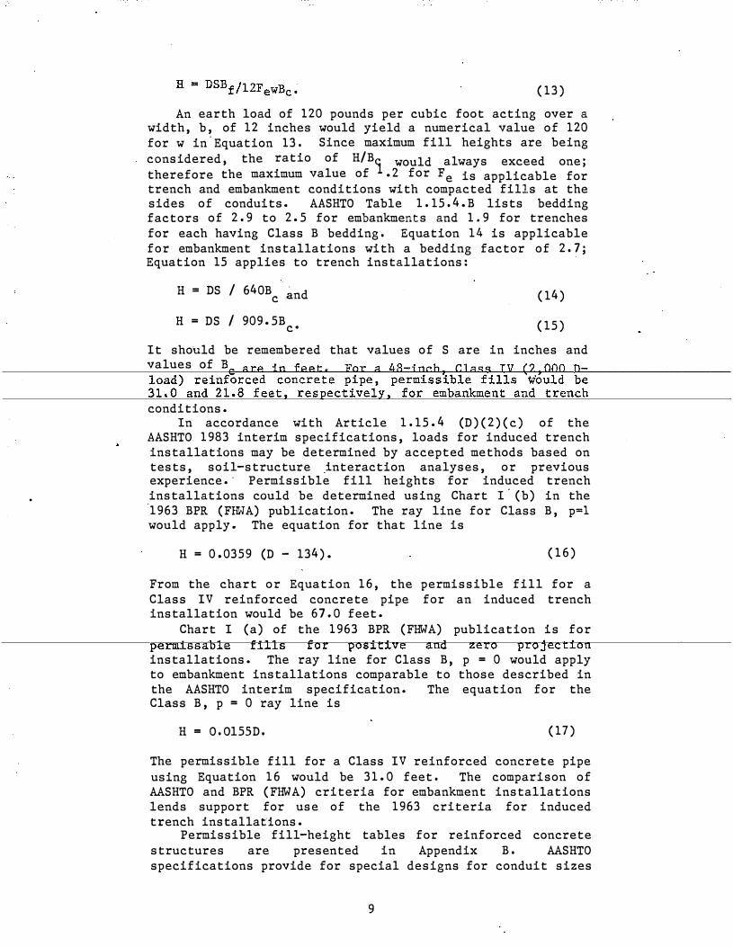
An earth load of 120 pounds per cubic foot acting over a width, b, of 12 inches would yield a numerical value of 120 for w in.Equation 13. Since maximum fill heights are being considered, the ratio of H/B would always exceed one; therefore the maximum value of l.2 for Fe is applicable for trench and embankment conditions with compacted fills at the sides of conduits. AASHTO Table 1. 15. 4.B lists bedding factors of 2. 9 to 2.5 for embankments and 1.9 for trenches for each having Class B bedding. Equation 14 is applicable for embankment installations with a bedding factor of 2. 7; Equation 15 applies to trench installations:
H = DS / 640B �nd c
H = DS / 909.5Bc•
(14)
(15)
It should be remembered that values of S are in inches and values of Be are in feet. Far a 48-jpch, Class TV (2 000 n-
conditions. In accordance with Article 1. 15.4 (D)(2)(c) of the
AASHTO 1983 interim specifications, loads for induced trench installations may be determined by accepted methods based on tests, soil-structure .interaction analyses, or previous experience.· Permissible fill heights for induced trench installations could be determined using Chart I· (b) in the ·1963 BPR (FHWA) publication. The ray line for Class B, p=l would apply. The equation for that line is
H = 0,0359 (D - 134). (16)
From the chart or Equation 16, the permissible fill for a Class IV reinforced concrete pipe for an induced trench installation would be 67.0 feet.
Chart I (a) of the 1963 BPR (FHWA) publication is for permissalJle fills for positive and zero projection installations. The ray line for Class B, p = 0 would apply to embankment installations comparable to those described in the AASHTO interim specification. The equation for the Class B, p = 0 ray line is
H = O. Ol5SD. (17)
The permissible fill for a Class IV reinforced concrete pipe using Equation 16 would be 31.0 feet. The comparison of AASHTO and BPR (FHWA) criteria for embankment installations lends support for use of the 1963 criteria for induced trench installations.
Permissible fill-height tables for reinforced concrete structures are presented in Appendix B. AASHTO specifications provide for special designs for conduit sizes
9
and/or D�load strengths beyond those liste d in the tables in Appendix B.
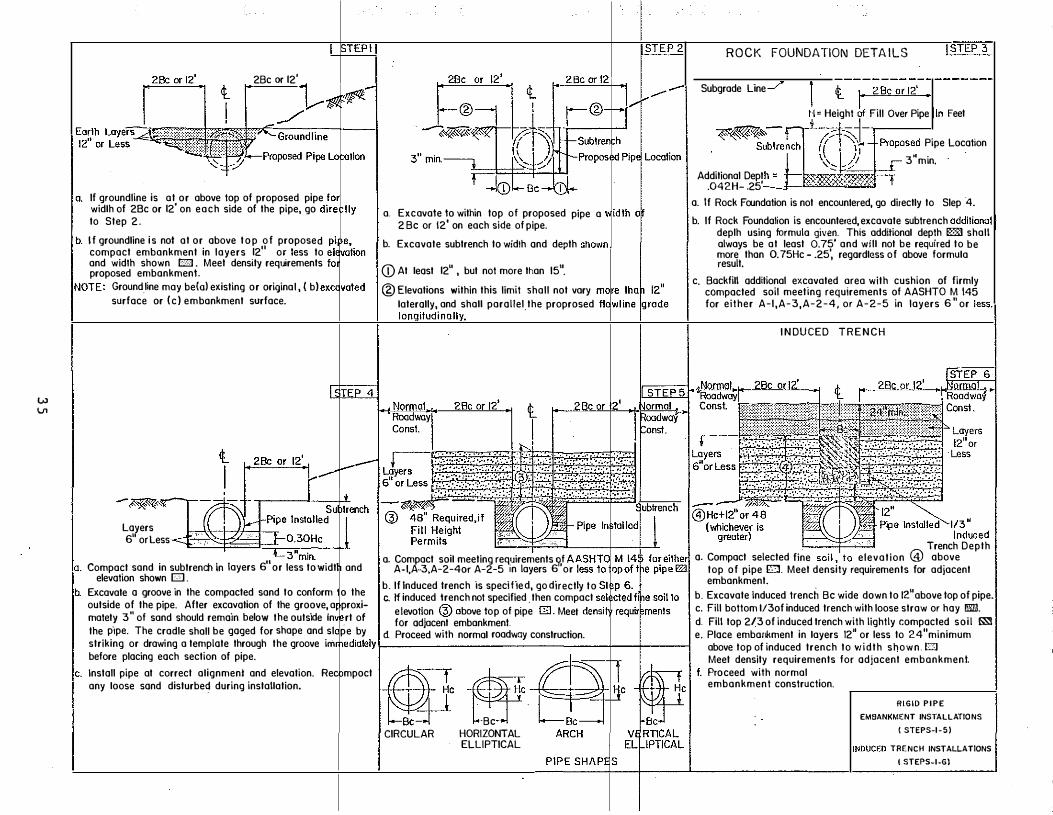
BEDDING Separate bedding standards, Appendix C, are proposed for
flexi.ble and rigid conduit installations. According to design criteria for rigid conduit, strength requirements are different for embankment, induced trench, and trench installations even when other design factors are similar. Flexible design criteria do not disting uish between embankment and trench installations · and do not provide for induced trench construction.
Bedding similar to that designated as Class B in the 1981 AASHTO Interim Specifications - Bridges is recommended for all installations. The foundation should be yielding and relatively uniform throughout the length of the structure. Provision for uniformity of the groundline (original, excavated, or embankment) to each side of the proposed installation is recommended. Backfill designated in the· 1982 FH\'IA proposed criteria is incorporated on the standards. Zero projection is shown for each type rigid
DURABILITY Indirectly, abrasion and corrosion · are structural
considerations since either or both may adversely affect the structural integrity of a conduit. In June 1�79, the e ngineering firm of Byrd, Tall amy, MacDonald, and Lewis issued a report titled " Kentucky Culvert Study An Engineering Review of Policies and Practices Related to Procurement of Culvert and Sewer Pipe." That report was prepared in fulfillment of requirements of the Kentucky Department of Finance's Contract CA 00738 issued at the request of the Department of Transportation. A report titled " Culvert Material Selection Policy Kentucky Department of Transportation" was issued in May 1981 . That report was prepared by consultants Kenneth s. Eff and Dr. Harry J, Sterling.
Information presented in those reports was used in preparation of current g uidelines, relative to durability, for use in selection of culvert materials. Those guidelines should be reviewe d periodically and revised in accordance with technological advancements and field performance data.
CAMBER Most culverts which are constructed on or near the
natural. ground surface and then covered by an embankment will eventually subside as the embankment weight compresses and consolidates the foundation soil. Damages resulting from subsidence may be greatly minimize d by placing the culvert on a cambered grade. The Division of Construction's Guidance Manual contains guidelines for camber design under Exhibit 63-4-8 which are included herein in Appendix D. It is recommended that consideration be given to adoption of
10

those guidelines as standards and including them in the Standard Drawings.
BIBLIO GRAPHY
1. "Reinforced Concrete Pipe Culve rts. " Circular Memorandum 22- 40, Bureau of Public Roads, April 4, 1957.
2. "Design and Installation Criteria for Reinforced Concrete Pipe Culve rts, " Portland Cement Association, September 1957.
3. "Reinforced Concrete Structural Design and Roads, August 1963.
Pipe Culverts Criteria for Installation , " Bureau of Public
4. "Corrugated Metal Pipe Culverts -- Structural Design Criteria and Recommended Installation Practices, " Bureau of Public Roads, June 1966.
5. "Corrugated Metal Pipe -- Structural Design Crite ria and Recommended Installation Practice, " Federal Highway Administration, Revised 1970.
6. "Des.ign Manual -- Concrete Pipe , " American Concrete Pipe Association, 1970.
7. "Handbook of Steel Drainage and Highway Constr uction Products, " American Iron and Steel Institute, 1971.
8. " Soil Enginee ring, " M. G. Spangler and R. L. Handy, Harper and Rowe Publishers, 1973.
9. "Design Manual -- Concrete Pipe , " American Concrete Pipe Association, 1978.
10. "Kentucky Culvert Study -- An Enginee ring Review of Peliey and Praetiees Related to Procurement of Cul,ert and Sewer Pipe;" Byrd, Tallamy, MacDonald and Lewis, June 1979.
11. "Modern Sewer Design, " American Iron and Steel Institute, 1980.
12, " Interim Specifications, Bridges, Association of State Highway and Officials.
1981," American Transportation
13. " Culvert Mate rial Selection Policy, " Kenneth S. Eff and Harry J. Sterling, May 7, 1981.
14. " Structural Design of Corrugated Metal Pipe , " Draft Copy, Federal Highway Administration, July 1982.
11
15. "Part I - Specifications, " American Association of State Highway and Transportation Officials, 1982.
16. ". Interim Specifications, Association of State Officials.
Bridges, High••ay and
12
1983," American Transportation

APPENDIX A
Fill-Height Tables for Flexible Conduit
. .

TABLE. 1
FILL HEIGHTS (FT) FOR 2 2/3" x 1/2" CORRUGATED STEEL PIPE. WITH HELICAL LOCK SEA.l1 OR HELICAL WELDED SEAt1 (MINIHlJ11 FILL - 2. 0 FT)
Diameter Metal Thickness (inch) (inches) 0.064 0.079 0.109 0. 138 0.168
12 213 266 373 480 586 15 170 213 298 384 469 18 142 177 248 320 390 21 122 152 213 274 335 24 106 133 186 240 293
27 94 213 260 30 85 192 234 36 71 160 195 42 1 48 53 66 93 120 146
54 59 82 106 130 60 74 95 117 66 87 106 72 79 97 78 90
' 84 83
14

FILL HEIGHTS (FT) FOR 2
TABLE 2
2/3" X 1/2" CORRUGATED STEEL PIPE WITH LONGITUDINAL RIVETED OR SPOT WELDED SEAM (MINIMill"l FILL - 2. 0 FT)
Diameter Metal Thickness (inch) (inches) 0.064 0.079 0.109 0. 138
12 92 101 130 136 15 74 80 104 109 18 61 67 86 90 21 53 57 74 77 24 46 50 65 68
27 41 44 57 60 30 37 40 52 54 36 30 33 43 45 42 34 47 74 77 48 30
54 36 57 60 60 52 54 66 49 72 45 78
84
15
0.168
142 114
94 81 71
63 56 47 81
63 57 51 47 43
40

TABLE 3
FILL HEIGHTS (FT) FOR 3" x 1" CORRUGATED STEEL PIPE WITH HELICAL LOCK SEAN OR HELICAL WELDED. SEAN (MINlllUN FILL - 2. 0 FT)
Diameter Metal Thickness (inch) (inches) 0.064 0. 079 0. 109 0.138 0. 168
36 81 102 143 184 225 42 70 87 123 158 193 48 61 76 107 138 169 54 54 68 95 123 150 60 49 61 85 110 135
66 44 55 78 100 123 72 40 51 71 91 113 78 37 47 66 84 104
90 32 40 57 73 90
96 38 53 68 84 102 36 50 64 79 108 47 61 75 114 45 58 71 120 42 55 67
126 52 64 132 50 61 138 58 144 56 150 52
16
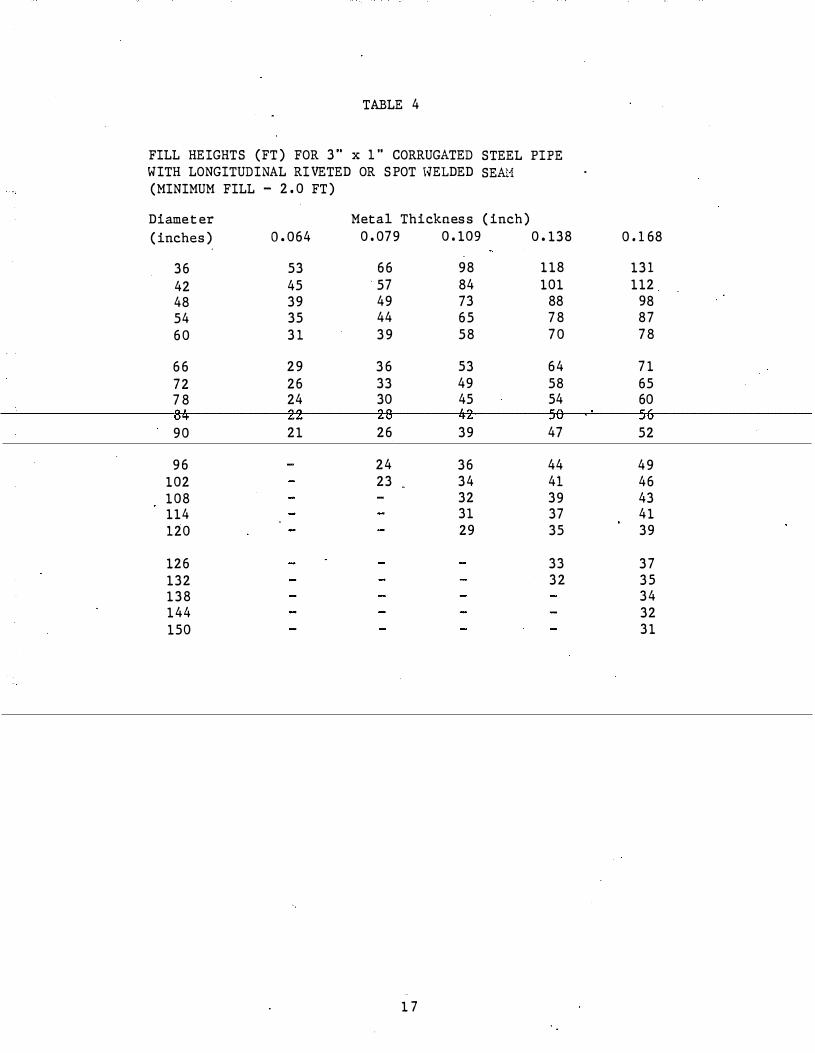
TABLE 4
FILL HEIGHTS (FT) FOR 3" x 1" CORRUGATED STEEL PIPE WITH LONGITUDINAL RIVETED OR SPOT \'IELDED SEA-'1 (MINIMUM FILL - 2.0 FT)
Diameter Metal Thickness (inch) (inches) 0.064 0.079 0.109 0. 138 0.168
36 53 66 98 118 131 42 45 57 84 101 112 48 39 49 73 88 98 54 35 44 65 78 87 60 31 39 58 70 78
66 29 36 53 64 71 72 26 33 49 58 65 78 24 30 45 54 60
90 21 26 39 47 52
96 24 36 44 49 102 23 34 41 46 108 32 39 43 114 31 37 41 120 29 35 39
126 33 37 132 32 35 138 34 144 32 150 31
17

TABLE 5
FILL HEIGHTS (FT) FOR 5" x 1" CORRUG;'\TED STEEL PIPE WITH HELICAL LOCK SE&'1 OR HELICAL \-IELDED SEAN (NINIMUN FILL - 2. 0 FT)
Diameter Metal Thickness (inch) (inches) 0. 064 0. 079 0.109 0. 138 0.168
36 72 90 127 164 200 42 62 77 109 140 172 48 54 68 95 123 150 54 48 60 84 109 133 60 43 54 76 98 120
66 39 49 69 89 109 72 36 45 63 81 100 78 33 41 58 75 92
90 29 36 50 65 80
96 34 47 61 75 102 32 44 57 70 108 42 . 54 66 114 40 51 63 120 38 49 60
126 46 57 132 44 54 138 52 144 50 150 48
18

TABLE 6
FILL HEIGHTS (FT) FOR 6" x 2" CORRUGATED STEEL PIPE WITH LONGITUDINAL SEAHS HAVING FOUR 3/4" BOLTS PER FOOT (MINIHUH FILL - 2.0 FT FOR DIAMETERS T\IROUGH 198 IN. AND 3.0 FT FOR DI&�ETERS 204 IN. THROUGH 306 IN) .
Diameter Metal Thickness (irich) (inches) 0. 109 0.138 0.168 0.188 0.218 0.249 0.280
60 46 68 90 103 124 146 160 66 42 62 81 94 113 133 145 72 38 57 75 86 103 122 133 78 35 52 69 79 95 112 123 84 33 49 64 73 88 104 114
90 31 45 60 68 82 97 106 96 29 43 56 64 77 91 100
108 25 50 57 69 81 88 47
120 23 34 45 51 62 73 80 126 22 32 42 49 59 69 76 132 21 31 40 46 56 66 72 138 20 29 39 44 54 63 69 144 19 28 37 43 51 61 66
150 18 27 36 41 49 58 64 156 17 26 34 39 47 56 61 162 17 25 33 38 46 54 59 168 16 24 32 36 44 52 57 174 16 23 31 35 42 50 55
180 15 22 30 34 41 48 53 186 15 22 29 33 40 47 51 192 21 28 32 38 45 so 198 20 27 31 37 44 48 204 20 26 30 36 43 47
210 19 25 29 35 41 45 . 216 25 28 34 40 44 222 24 27 33 39 43 228 23 27 32 38 42
19

TABLE 6 (continued)
Diameter Metal Thickness (Inch) (inches) 0.109 0.138 0.168 0.188 0. 218 0.249 0.280
234 23 26 31 37 41 240 25 31 36 40 246 25 30 35 39 252 29 34 38 258 28 34 37
264 28 33 36 270 27 32 35 276 31 34 282 31 34 288 30 33
294 32 300 32
20

FILL HEIGHTS PIPE-ARCHES
Span x Ris e (in. x in.)
17 X 13 21 X 15 24 X 18 28 X 20 35 X 24
42 X 29 29 X 33 57 X 38 64 X 43 71 X 47
77 X 52 83 X 57
(FT) FOR 2
He tal Thickness
(in . )
0.064 0. 064 0. 064 0. 064 0. 064
0. 064 0. 079 0. 109 0. 109 0. 138
0. 168 0. 168
*Figures in parenthzsis· pressure - tons/ft ·
TABLE 7
2/3" x 1/2" CORRUGATED STEEL
Minimum Corner Radius Fill (ft)
(in.) Min Max*
3 1.5 12 (2. 0) 3 1. 5 10 (2. 0) 3 2. 0 7 (2. 0) 3 2. 0 5 (2. 0) 3 2.5 7 (3. 0)
3 1/2 2. 5 7 (3. 0) 4 2.5 6 (3. 0) 5 2. 5 8 (3. 0) 6 2.5 "9 (3. 0) 7 2. 0 10 (3. 0)
8 2. 0 5 (2. 0) 9 2. 0 5 (2. 0)
are m�nirnum perrniss able soil bearing
21

TABLE 8
FILL HEIGHTS (FT) FOR EITHER 3" x 1" or 5" x 1" CORRUGATED STEEL PIPE-ARCHES (REQUIRED SOIL BEARING PRESSURE - 2.0 TONS/FT2, MINIMUH)
Hinimum Heta1 Corner
Span x Rise Thickness Radius Fill (Ft) (in. x in.) ·· (in.) (in.) Hin Hax
40 X 31 0.064 5 2.5 8 46 X 36 0.064 6 2.0 8 53 X 41 0.064 7 2.0 8 60 X 46 0.064 8 2.0 8 66 X 51 0.064 9 1.5 9
73 X 55 0.064 12 1.5 11 81 X 59 0.064 14 1.5 ·u . . 87 X 63 0.064 14 1.5 10 95 X 67 0.079 16 1.5 11
103 X 71 0.109 16 2.0 10
112 X 75 0.109 18 2.0 10 117 X 79 0.109 18 2.0 10 128 X 83 0.138 ui 2.0 g· 137 X 87 0.138 1.8 2.0 8 142 X 91 0.168 18 2.0 7
2 2
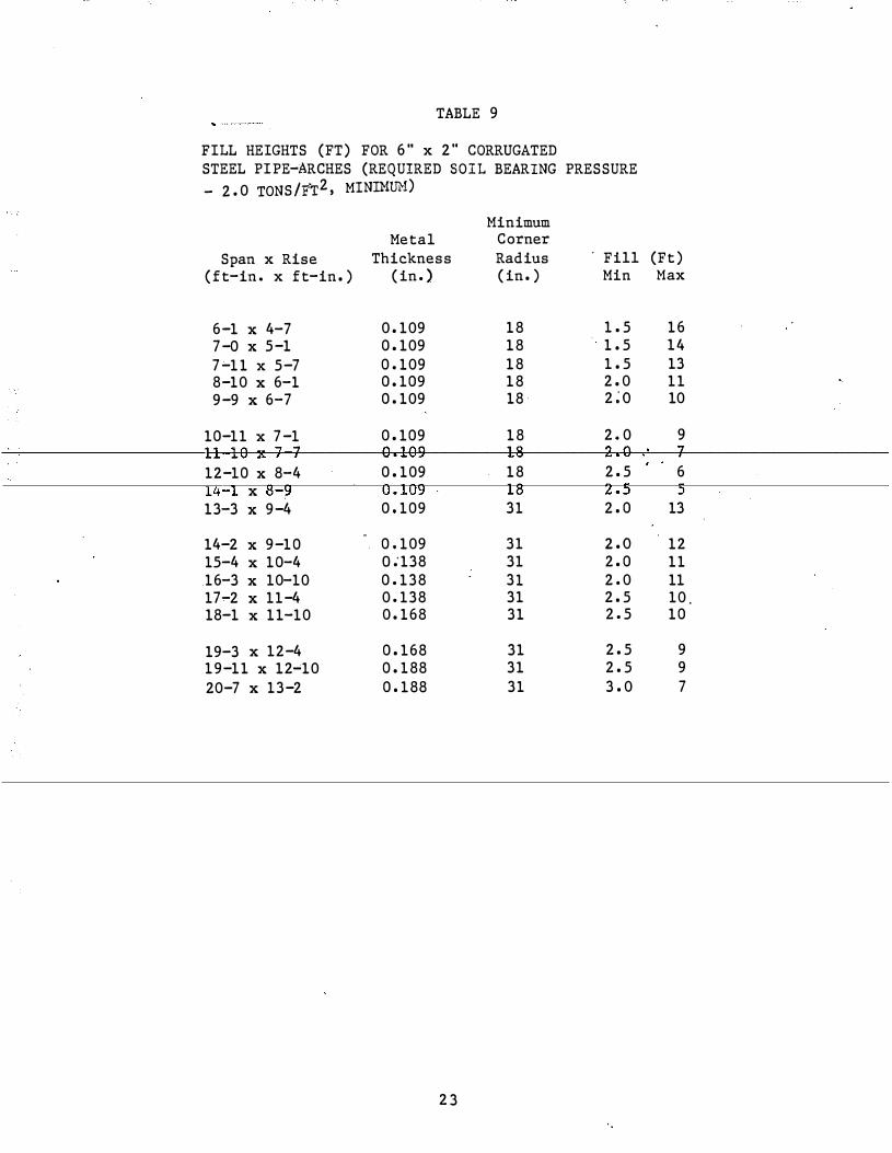
TABLE 9
FILL HEIGHTS (FT) FOR 6" x 2" CORRUGATED STEEL PIPE-ARCHES (REQUIRED SOIL BEARING PRESSURE - 2.0 TONS/FT2, MININlJH)
Minimum Metal Corner
Span x Rise Thickness Radius . Fill (Ft) (ft-in. x ft-in.) (in.) (in.) Min Max
6-1 X 4-7 0.109 18 1.5 16 7-0 X 5-1 0.109 18 1.5 14 7-11 x 5-7 0.109 18 1.5 13 8-10 X 6-1 0.109 18 2.0 11 9-9 X 6-7 0.109 18 2;o 10
10-11 X 7-1 0.109 18 2.0 9
12-10 X 8-4 0.109 18 2.5 6 -1 X 8-9 0.109 18 z.
13-3 X 9-4 0.109 31 2.0 13
14-2 X 9-10 0.109 31 z.o 12 15-4 X 10⁻⁴ o.-138 31 2.0 11 16-3 X 10⁻¹⁰ 0.138 31 2.0 11 17-2 X 11-4 0.138 31 2.5 10. 18-1 X 11-10 0.168 31 2.5 10
19-3 X 12-4 0.168 31 2.5 9 19-11 X 12�10 0.188 31 2.5 9 20-7 X 13-2 0.188 31 3.0 7
23

TABLE 10
FILL HEIGHTS (FT) FOR 2 2/3" x T/2" CORRUGATED ALUHINUM PIPE WITH HELICAL LOCK SEAl.'! (HINIMUH FILL - 2. 0 FT)
Diameter Netal Thickness (inch) (inches) 0.060 0.075 0.105 0.135 0.164
12 155 194 271 349 426
15 124 155 217 279 341
18 103 128 181 233 284
21 88 110 154 199 243
24 77 96 136 175 213
27 68 86 120 155 189
30 62 77 108 140 170
36 51 64 90 116 141
42 44 55 77 99 122
48 47 66 86 107
54 54 70 87
66 46 57
72 45
TABLE 11
FILL HEIGHTS (FT) FOR 2 2/3" x 1/2" CORRUGATED ALUl1INUl1 PIPE WITH RIVETED LONGITUDINAL SEAH (NINIMUH FILL - 2.0 FT)
Diameter Hetal Thickness (inch) (inches) 0.060 0.075 0.105 0.135 0.164
50 so 86 90 93 15 40 40 69 72 74 18 33 33 57 60 62 21 2.8 28 49 51 53 2.4 25 25 43 45 46
27 22 22 38 40 41 30 20 20 34 36 37
. 36 16 16 28 30 31 42 22 28 so 52 53 48 25 43 45 47
54 38 40 41 60 36 37 66 33 34 72 31
24
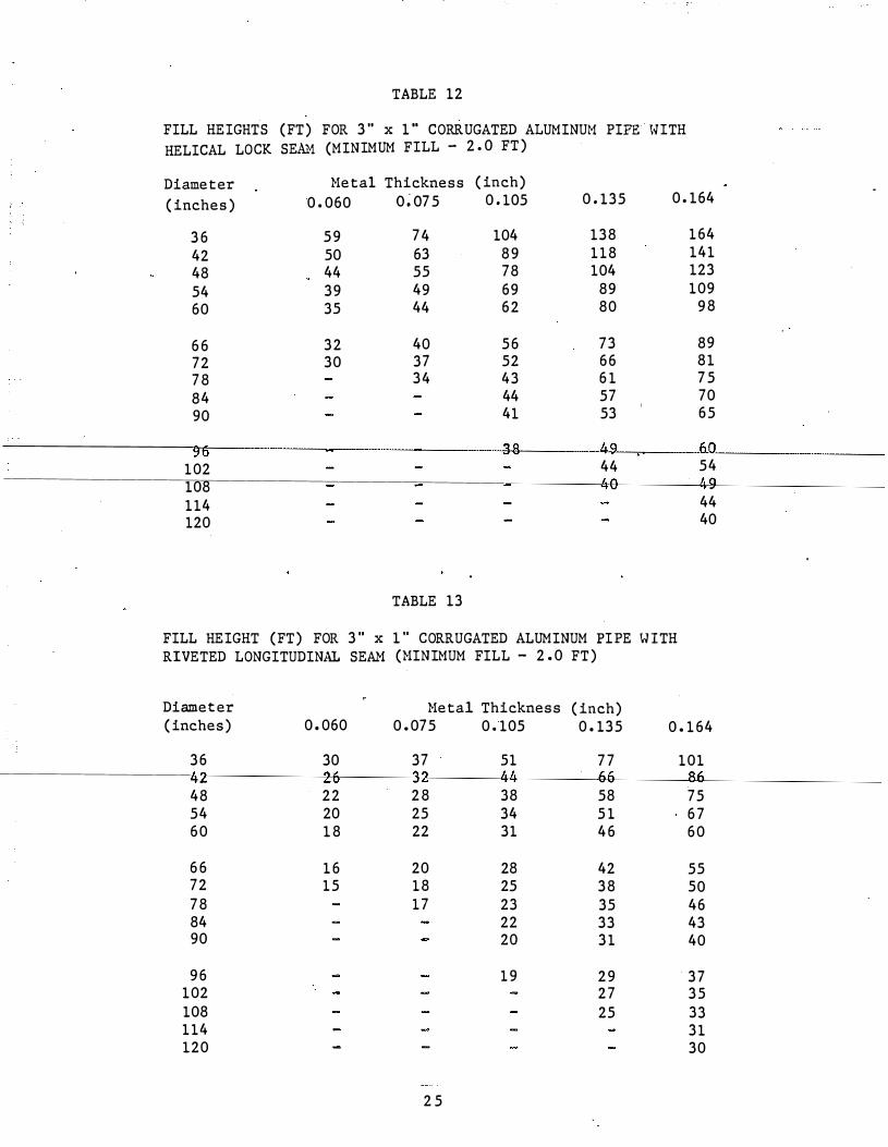
TABLE 12
FILL HEIGHTS (FT) FOR 3" x 1" CORRUGATED ALUMINUM PIPE IHTH HELICAL LOCK SE�� (MINIMUM FILL - 2. 0 FT)
Diameter Heta1 Thickness (inch) (inches) 0.060 o;o75 0.105 0.135 0.164
36 59 74 104 138 164 42 50 63 89 118 141 48 44 55 78 104 123 54 39 49 69 89 109 60 35 44 62 80 98
66 32 40 56 73 89 72 30 37 52 66 81 78 34 43 61 75 84 44 57 70 90 41 53 65
102 44 54 108 114 44 120 40
TABLE 13
FILL HEIGHT (FT) FOR 3" x 1" CORRUGATED ALUMINUM PIPE \liTH RIVETED LONGITUDINAL SEAM (HINIMUM FILL - 2.0 FT)
Diameter Hetal Thickness (inch) (inches) 0.060 0.075 0.105 0.135 0.164
36 30 37 51 77 101
48 22 28 38 58 75 54 20 25 34 51 67 60 18 22 31 46 60
66 16 20 28 42 55 72 15 18 25 38 50 78 17 23 35 46 84 22 33 43 90 20 31 40
96 19 29 37 102 27 35 108 25 33 114 31 120 30
2 5
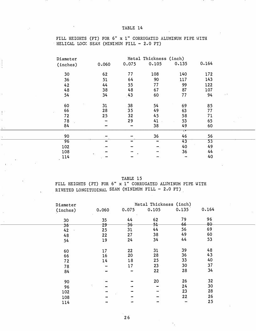
TABLE 14
FILL HEIGHTS (FT) FOR 6" x 1" CORRUGATED ALUHINUH PIPE IHTH · HEL ICAL LOCK SEAl'! (HINIH!Th! FILL - 2. 0 FT)
Diameter Metal Thickness (inch) (inches) 0. 060 0.075 0.105 0.135 0.164
30 62 77 108 140 172 36 51 64 90 117 143 42 44 55 77 99 122 48 38 48 67 87 107 54 34 43 60 77 94
60 31 38 54 69 85 66 28 35 49 63 77 72 25 32 45 58 71 78 29 41 53 65 84 38 49 60
90 36 46 56 96 3 5
102 40 49 108 36 44 114 40
TABLE 15 FILL HEIGHTS ( FT) FOR 6" x 1" CORRUGATED AL!Jt.!INUM PIPE WITH RIVETED LONGITUDINAL SEAM (MINIHUM FILL - 2.0 FT)
Diameter Metal Thickness (inch) (inches) 0.060 0.075 0.105 0.135 0.164
30 35 44 62 79 96
42 25 31 44 56 69 48 22 27 38 49 60 54 19 24 34 44 53
60 17 22 31 39 48 66 16 20 28 36 43 72 14 18 25 33 40 78 17 23 30 37 84 22 28 34
90 20 26 32 96 24 30
102 23 28 108 22 26 114 25
2 6
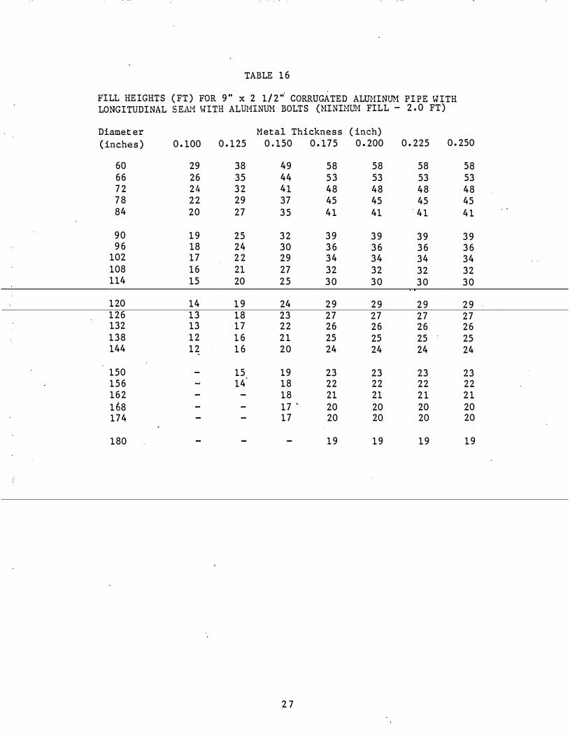
TABLE 16
FILL HEIGHTS (FT) FOR 9" x 2 1/2" CORRUGATED ALUHINill! PIPE WITH LONGITUDINAL SEA."1 \HTH ALIDHNUH BOLTS (HINIHU1 FIL L - 2.0 FT)
Diameter Metal Thickness (inc. h) (inches) 0.100 0.125 0.150 0.175 0.200 0.225 0.250
60 29 38 49 58 58 58 58 66 26 35 44 53 53 53 53 72 24 32 41 48 48 48 48 78 22 29 37 45 45 45 45 84 20 27 35 41 41 41 41
90 19 25 32 39 39 39 39 96 18 24 30 36 36 36 36
102 17 22 29 34 34 34 34 108 16 21 27 32 32 32 32 114 15 20 25 30 30 30 30
120 14 19 24 29 29 29 29 126 13 18 23 27 27 27 27 132 13 17 22 26 26 26 26 138 12 16 21 25 25 25 25 144 12 16 20 24 24 24 24
150 15 19 23 23 23 23 156 14 18 22 22 22 22 162 18 21 21 21 21 168 17 ' 20 20 20 20 174 17 20 20 20 20
180 19 19 19 19
2 7

TABLE 17
FILL HEIGHTS (FT) FOR 9" x 2 1/2" CORRUGATED ALUMINUJ:I PIPE WITH LONGITUDINAL SEAH WITH STEEL BOLTS (HINIHUi'J FILL - 2.0 FT)
Diameter Heta1 Thickness (inch) (inches) 0.100 0.125 0.150 0.175 0.200 0.225 0.250
60 31 45 60 70 81 92 103 66 28 41 54 64 74 84 94 72 25 37 50 58 . 67 77 86 78 23 35 46 54 62 71 79 84 22 32 42 50 58 66 73
90 20 30 40 47 54 61 68 96 19 28 37 44 50 57 64
102 18 26 35 41 47 54 60 108 17 25 33 39 45 51 57
120 15 22 30 35 40 46 51 126 14 21 28 33 38 44 49 132 14 20 27 32 37 42 47 138 13 19 26 30 35 40 44 144 12 18 25 29 33 38 43
150 18 24 28 32 36 41 156 17 23 27 31 35 39 162 22 26 30 34 38 168 21 25 29 33 36 174 20 24 28 31 35
180 23 27 30 34
2 8

TABLE 18
FILL HEIGHTS (FT) FOR 2 2/3" X 1/2" CORRUGATED ALUHIHUN PIPE-ARCHES
Minimum Metal Corner
Span x Ri� Thickness Radius Fill ( ft) (in. x in.) (in.) (in.) Nin Nax *
17 X 13 0.060 3 1.5 12 (2.0) 21 X 15 0.060 3 1.5 10 (2.0) 24 X 18 0.060 3 2.0 7 (2.0) 28 X 20 0.060 3 2.0 5 (2.0) 35 X 24 0.060 3 2.5 7 (3.0)
42 X 29 0.060 3 1/2 2.5 7 (3.0) 49 X 33 0.079 4 2.5 6 (3.0) 57 X 38 0.135 5 2.5 8 (3.0)
71 X 47 0.164 7 2.0 (3.0)
*Figures in parenthesis are bearing pressure - tons/ft2
minimum permissible soil
TABLE 19
FILL HEIGHTS (FT) FOR 3" x 1" CORRUGATED ALUMIHUM PIPE-ARCHES (REQUIRED SOIL BEARING PRESSURE - 2.0 TONS/FT2, MINIMUM)
Minimum Metal Corner
Span x Rise Thickness Radius Fill (ft) (in. x in.) (in.) (in.) Min Max
40 X 31 0.060 5 2.5 8 46 X 36 0.060 6 2.0 8 53 X 41 0.060 7 2.0 8 60 X 46 0.060 8 2.0 8 66 X 51 0.060 9 1.5 9
73 X 55 0.075 12 1.5 11 81 X 59 0.075 14 1.5 11 87 X 63 0.105 14 1.5 10 95 X 67 0.105 16 1.5 11
103 x 71 0.135 16 2.0 10
112 X 75 0.135 18 2.0 10 117 X 79 0.164 18 2.0 10
29

TABLE 20
FILL HEIGHTS (FT) FOR 9" x 2 1/2" CORRUGATED ALUMINUM PIPE-ARCHES, 31.8" CORNER RADIUS, \HTH 3/4" ALIDIINUM OR STEEL BOLTS AT 4 1/3 PER FOOT (REQUIRED SOIL BEARING PRESSURE - 2.0 TONS/FT2, MINL�UM)
Metal Span x Rise Thickness Fill (ft) (ft-in. x ft-in.) (in. ) Min Max
6.-7 X 5-8 0. 100 1. 5 23 7-9 X 6-0 0. 100 1. 5 20 8-5 X 6-3 0. 100 1. 5 18 9-3 X 6-5 0. 100 2. 0 16 9-11 X 6-8 · o . too 2. 0 15
10-9 X 6-10 0. 100 2. 0 14 11-5 X 7-1 0.100 2. 0 13 12-3 X 7-3 0. 100 2.0 1 12-11 X 7-6 0. 100 2. 5 11 13-1 X 8-4 0. 100 2. 5 11
13-11 X 9-5 0. 100 2. 5 11 14-8 X 9-8 0. 100 2. 5 10 15-4 X 10-0 0.125 2. 5 l l 16-1 X 10⁻⁴ 0. 125 2. 5 10 16-9 X 10⁻⁸ 0.125 2. 5 10
17-3 X 11-0 0. 15 0 2. 5 10 18-0 X 11-4 0. 150 2. 5 9 18-8 X 11-8 0. 150 3. 0 9
30

. .
Fill-Height Tables for Rigid Conduit

TABLE 21. FILL HEIGHTS (FT) FOR CIRCULAR REI}ITORCED CONCRETE PIPE (DIAMETERS 15 THROUGH 144 INCHES )
EMBANKHENT INS TALLATIONS
S TANDARD IND UCED TRENCH
Fill Height (ft) 2. 0 � 21. 0 21. 1 - 3 1. 0 31. 1 - 47 . 0 47.1 - 67 . 0 67 . 1 - 103. 0 D-Load Class III IV V IV V
Fill Height (ft) D-Load Class
TRENCH INSTALLATIONS
2.0 - 15.0 III
TABLE 22
15. 1 - 22. 0 IV
22. 1 - 33. 0 v
FILL HEIGHTS (FT) FOR HORIZONTAL ELLIPTICAL REINFORCED CONCRETE PIPE (SIZ ES 14 x 23 THROUGH 67 x 106 INCHES )
EHBANKMENT INSTALLATIONS
STANDARD INDUCED TRENCH
Fill Height (ft) 1. 0-21. 0 D-Load Class HE III
21. 1 - 31. 0 HE IV
TRENCH INSTALLATION
31. 1 - 44. 0 HE III
Fill Height (ft) 2. 0 - 15. 0 D-Load Class HE III
15. 1 - 22. 0 HE IV
32
44. 1 - 67 . 0 HE IV

TABLE 23
FILL HEIGHTS (FT) FOR VERTICAL ELLIPTICAL REINFORCED CONCRETE PIPE (SIZES 45 x 29 THROUGH 106 x 57 INCHES)
STA.'IDARD EHBANKHENT INSTALLATIONS
INDUCED TRENCH
Fill Height (ft) 2.0-21.0 21.1-31.0 31. 1-47. 0 47. 1-62.0 6 2.1-103. 0 103.1-138. 0 D-Load Class VE III VE IV VE V VE IV VE V VE VI
TRENCH INSTALLATION
Fill Height (ft) 2. 0 - 15.0 15.1 - 22.0 22. 1 - 33.0 33. 1 - 44.0 D-Load Class VE III VE IV VE V VE VI
TABLE 24
FILL HEIGHTS (FT) FOR REINFORCED CONCRETE ARCH PIPE (SIZES 11 x 18 TllllOJIGH 1 06 x 1 68 INCHES)
EMBANKMENT INSTALLATIONS STANDARD INDUCED TRENCH
Fill Height (ft) 2. 0 - 21.0 21. 1 - 31. 0 31. 1 - 47. 0 47. 1 - 6 7. 0 D-Load Class III IV III IV
Fill Height (ft) z ;o - 15.0 D-Load Cl ass III
TRENCH INSTALLATION
33
15.1 - 22. 0 IV

APPENDIX C
Proposed Bedding Standards
w en
2Bc or 12'
If groundline is at or above top of proposed pipe widlh of 28c or 12' on each side of the pipe, go to Step 2. If groundline is not at or above top of proposed compact embankment in layers 12" or less to and widlh shown (3] . Meet density requirements proposed embankment.
Ground_line may be(o) existing or original , { b) exc9voted surface or (c) embankment surface.
Layers �-�i£j l l 6" or less � z=t�;:�Hc
3" ffilll�! 1''-i�/1 j ! a. Excavate to within top of proposed pipe a
2 Be or 12' on each si�e of pipe. b. Excavate subtrench to widlh and depth
CD " 5" At least 12 , but not more than I . @ Elevations within this limit shall not vary
laterally,. and shall parallel. the proprosed
11 ···-··· a. Compact soil meeting requirements �f Compact sand in sub trench in layers 6 or less to widt and A-I A-3 A-2-4or A-2-5 in layers 6 'or elevation shown D . ' '
h · · 1· d d' 1 . b. If Induced Irene 1s spect te , go trect y to Excavate a groove 1n the compacted sand to conform o the c. If induced trench not specified then compact outside of the pipe. After excavation of the groove, a proxi- 1 1. '3' b 1 of p'ipe.
r::'1 M 1 " · b 1 h 'd . 1 e evo mn 12.1 a ave op � . ee matety 3 of sand should remam e ow t e outst e 1n .rt o for adjacent embankment.
ROCK FOUNDATION DETA ILS
Subgrade Line t Height 9f Fill Over Pipe lin Feet
Additional Dept *�� ............ ±� -q:�--< . 042H- .25' "'�l'..').x,-.. � 1
Pipe Location 3"min.
a. If Rock Foundation is not encounlered, go directly to Slep A. b. If Rock Foundation is encountered, excavate subtrench additional !
deplh using formula given. This addliional depth � shall always be at least 0.75' and will not be required to be more than 0. 75Hc - .25� regardless of abO\Ie formula result.
c. Backfill additional excavated area with cushion of firmly compacted soil meeting requirements of AASHTO M 145 for either A-I,A-3,A-2-4, or A-2-5 in layers 6 " or
INDUCED TRENCH
Trench Depth fareitherl a. Compact selected fine soi l , ' to elevation @ above
top of pipe D. Meet density requirements for adjacent embankment.
b. Excavate Induced trench Be wide down to 12."above top of pipe. c. Fill bottom l/3of induced trench with loose straw or hay �. d. Fill top 2/3 of induced trench with lightly compacted soil �
the ptpe. The cradle shall be gaged for shape and sl pe by d Proceed with normal roadway construction. striking or drawing a template through the groove inl ediatelyl-------------------+--t----1 before placing each section of pipe.
e. Place embankment in layers \211 or less to 24"minimum above top of induced trench to width shown. D
Install pipe at correct alignment and elevation. Rec mpoct any loose sand disturbe� during installation.
CIRCULAR
-�T� Be
HORIZONTAL ELLIPTICAL
Meet density requirements for adjacent embankment. Proceed with normal embankment construction.
RIGID PIPE
EMBANKMENT INSTALLATIONS
( STEPS-1-5)
TRENCH INSTALLATIONS
I STEPS-I-G)

w "'
<t_ I S E P I t TEP 2 ROCK FOUNDATION DETAILS !STEP 3
--�--r-+--\�- I /, � -=d•_L:�•::._ _____ t_r _ _ _ _ _ "' ?("R Greater Groundlme · // j ! H•Heighi of
tho� He I � LGro ndline I ����:f' P1p
�� r-�r-i- -� r ---t=i 'f:;"f�\ . Subtrench . ! -:;:::-f�\ tJ_ p d Pi e Sub trench /::��.\-___ Propo_sed' P1Pe { 1 , 1 r:--Proposed P1p � '�J ) f" Lro �.56 P L 1 ( , ) : Locahon \ \ _I . 'I · Location ,\ /i- 0 0 100 \ \ 1 ; / '�¥ � �/ '..:--..:r�..::____ _j_
3'' min. CD\- · _ ,.. � LCD Additional Depth= � - L311 min. a. Trench condition Is when groundline elevalion is grefrter I; - _ 1--- Be - 1 .042H- .25' __j
than He above top of proposed pipe. a. Excavate subtrench to w1dlh and depth shown. . . . b. Trench walls may be constructed vertical. Fo must ation pur a. If Rock Foundation 1snot encountered, go directly to Step4.
NOTE: Groundllne may be {a) existing or original poses t�e detail depicts a sloping wall tren�h. Which v�r b. lf Rock Foundation is encountered, excavate subtrench oddi-(b) excavated surface or (c) embankment sur pee. method 1s used , the trench walls shall rematn ymme neal f 1 d th . fl 1 . Th. ddT 1 d th � about the centerline of the pioe 1ona ep usmg ormu a gtven. 1S a 1 10na ep . 11 11 • • shall always be at least 0.751 and will not be required to be <D 12 Min., 15 Max. more than 0.75He -.25', regardless_ of above formula
@ Sleping of trench v.:olls may begin at any eleva ion gr ater t�an result. 1--------------------r-1,, ---1 12. above top of p1pe. The subtrench shall always e reqUired c. Backfill additional excavated area with eorlh cushion of
tS EP 4 @ 12 .. Min to He Max firmly compacted soil meeting requirements of AASHTO · · M 145 for either A-1, A-3, A-2-4,or A-2-5 in layers
�\ 6" or less.
Grourmnn STEP 5
I __ j ---- .-+>; Groundlin�'\.'\, . . . . . .-, ·.-.. ·.�::!:· · ··· · ··'·''·'·'.:'·:·· � �· � -�� ffi· �-� �� / . lpe lnstalled - ·
· · · · · . . . _-·: · • • . · :·.: ·· ·. La 6.. T J ...-:!:--.. / �;·::: 4 .�<:::··::.�.:.�.;;: or :::. I Subtrench , )) r:t\ 11 • 2.· · · :::: _. , · Be Be - Be - Be Ltrtt§�t¥:-�g=! r( 0·30 He � 4B Req�1red, &,-·if� --r CIRCULAR HORIZONTAL ARCH VERTICAL _I •f flU He•ght ·· · · · <l·'·OC:'i:: I ELLIPTICAL ELLIPTICAL
�"J L , . permits ."( ! '�· subtren h � � + Layers 6 3 min. z 1 . · · _j P IPE SHAPES
a. Compact sand in subtreneh in layers 6" or less to wid h and \_Pipe Install d
elevation shown c::J. · b. Exc�vate a gro?ve in the compoct�d sand to conform jo the_ · a. Compact selected soil meeting requirements f AA H1P I outs1de of the p1pe. After excavation of the groove, a prox1- M 145 for either A-I A-3 A-2-4 or A-2-5 i layer 6 or ! mately 311 of sand should remain below the outside in ert of less to Top of pipe ·�·-
' the pipe. The cradle shall be gaged for. shape and s ppe by b. In a unifo!m sy!Jlmetrica\ manner �ompoct sel ct�� ine soil I striking or drawi�g a templot� throug� the groove· imfedi- to
-�levotlon !(!) above top of ptpe m layers 6 o less RIGID PIPE
ately before placmg each section of p1pe. E::l c. Install pipe at correct alignment and eleva1ion. Recotnpact c. Proceed ";',ith trench backfill_ I� a symmet_rica man. er i� TRENCH
any loose sand disturbed during installalion. layers 12 or less to the ongmol groundhne s deft ed m INSTA LATIONS Step I. L

v.> -.j
Be Be t B e
StructuroJ
/Gro�ndll�� Layers 6 ' o r I
Ia. If groundline is at or above an elevation 3" below the bot�om at I the proposed pipe, prepare the groudline by leveling or ex9avating to provide a surface elevation 3" below the bottom of the proposed pipe for Be on each side. If lhe ground line is below the required elevation, compact! embankment inJayers 12"or less to elevation shown an,-J each side ITIITJ. Meet density requirements for proposed embankment.
NOTE: Groundline �oybe(�) e_xistlng
t I � /Pipe Installed
�--�-�� b. Excavate a groove in the compacted structural fill
the outside oftne pipe. After excavation of the approximately 3" of structural fill should outside invert of the pipe. The cradle shall be shape and slope by striking or drawing a template groove immediately before placing each section of
c. Install pipe at correct alignment and elevation. any loose structural fill disturbed during installation.
_...
Place structural fill to elevation shown and width Be or more on each side of proposed p lpeEZ:Zp . Structural fill shall be firrnly·compacted soil me
_et�rg
requirements of AASHTO M 145 for either · · · - · -or A- 2-5.
Normal
Roadway Constr.
CD 4B" Required,il fill Height permits
t Be Be
a. Place additional structuol fill to an elevation no 1�ss mqn above top of pipe to no less than Be on each Lifts within the limits of the pipe shall be
b. Compact selected fine soil to elevation CD pipe c::J. Meet density requirements of adjo9ent etpbankment.
+++� �r CIRCULAR
PIPE SHAPES
ROCK FOU N DAT I O N DETAILS
----r----�r������� Subgrade Line
'· If Rock Foundation is not encountered, go directly to Step 4.
If Rock Foundation is encountered,excovate subtrench,odditionoll depth using formula given. This additional depth �shall always be at least 0.75' and will not be required to be more than 0.75Hc- .25: regardless of above formula result.
Backfill additional excavated area with structural fill OS
FLEXIBLE PIPE
EMBANKMENT
INSTALI.ATIONS

w 0:>
"-''
�t
Greater than 1211
l\ �./
� \ ' �rou
U\)U:Jt:"U Pip•
0 Trench condition is when groundline elevation is grlater than 12" above top of proposed ipe and /or is not prepared as required for flex.iCie pipe embankm nt instal.
NOTE= Ground line may be {a} existing or original {b) excavated surface or (c) embankment su ace.
ISTEP 2 ROCK FOUNDATION DETAILS I STEP 3 4
��-�--·U 4dundline
Subgrode Line----.... � �--�-----4_--r-----�,·""''" I
T""" JL_I (T}P;roposed i Pipe
L� f.-/ n�nhn I I I ®
I H =Height of 'IFill Over in Feet
I
f , Location /. l '\d---- Proposed Pipe
\ J I --�.:::._!_. ___l min. 3" min JQ}-1 �-Be __J 1.-Q) ���';:'": -���h�
a Excavate subtrench to width and depth shown . b: Trench Willis may be constructed verticaL r illus ration pur a. If Rock Foundation is not encountered, go dtrectly to Step 4.
poses, the detail depicts a sloping wall trench. Which \l_er b. If Rock Foundalion is encountered, excavate subtrench oddi-method Is used .�he trench W(_JIIS shall remain ymm !neal tiona! depth using formula given. This additional depth � about the centerline of the ptpe. shall always be at least 0. 75' and will not be required to be CD 2411 Min. more than 0.75Hc - .25� regardless of above formula ® Sloping of trench walls may begin at any eleva ion gr ater t�an result. . . . I 1t I 12" above top of pipe. The subtrench shall q ways e requ�red c. Backfill additional excavated area w1th cush1on of firmly EP 4 · compacted soil meeting requirements of AASHTO M 145
� C�-�---, blr
J �Pipe Jnstallec
=:[0.30 Hc
-. " /; Layers 6 J min. or Less
�\
a . Compact slructural fill meeting requirements of AA ·H Ill M 145 for either A-I, A-3, A-2-4,or A-2-5 in subtr nch in layers 6" or less to width and elevation shown
b. Excavate a groove in the compacted structural fill to c nform to the outside of the pipe. After excavation of the groove, a proximately 3"of structural fill should remain below theoutsid invert of the p1pe. The cradle shall be gaged fOr shape and s ope by striking or drawing a template through the groove im ediately before placing eadl section of pipe.
c. Instal l pipe at correct alignment and elevation. Recofnpact any loose structural fill disturbed during installatio� .
!sTEP 5
Groondlin� . .... .. j , LOtters 6 or ! Less
@ 48"Required, if fill Height permits
\_ Pipe lnstal)ed a. Compact structural fill in layers 611 or less tlelevdtion 1211
above fop of pipe. Lifts within limi1s of pip shalll be placed alternately.
b. In a uniform symmetrical manner compact set cted fine soil to elevation @ above top of pipe in layer 6 " less �.
c .. Proceed with french backfill in a symmetrica l manrler in layers 12" or less to the original ground line ?s defimed in Step I.
for either A-I,A-3,A-2-4, or A-2-5 in layers 6" or less.
��123 1"-I-Be
CIRCULAR
PIPE
/t'\ t �c
PIPE ARCH
SH APES
FLEXIBLE PIPE TRENCH
INSTALLATION

APPENDIX D
Camber Design Guidelines (from Division o f Construction ' s Guidance Hanual)

E x a m p l e l ; 4 - La n c D i v :d e d H i g h w a y
1 8 '
I Hcu·df'O'n1 I
I
I Ptp e fo be Installed fo , 1
7.94.30
or Gravel
Cambered Fla .., '-"'"'ei 1 1 S"f-.r f } · 50 + · 79 +. 30 .., - ""-.. r 789.00 . s4-' Srro•yht G�"e>o'e Flo ...- Lme
M e d i a n :
1 , F r om the f i l l h t . v s se ttle m e n t c u r ve , r e a d s e t t l e m e n t o f . O Z S f t . p e r fo�t o f s o i l b e low f l ow l ine to b e e xp e c te d unde r 1 7 ' fi l l .
2 , T ota l s e tt l e m e n t = 1 8 ( . 0 2 8) = • 50 ' = cam be r .
C e nte r l in e o ( R oa d w a v O ·:c r I n l e t P e> r t i o n o f C u l ve r t :
1 . F r om the f i l l h t . v s s e t t le m e nt c u r ve , r e a d se t t l e m e n t o f . 0 3 2 f t . p e r foot o f s o il b e low flow t in e t o be e xp e c t e d une r 1 9 ' f i l l .
Z . Total s e ttlement = 1 7 ( . 0 3 2. ) = . 54 ' = cam be r .
Cente r line o f R oa d ,•. a y O ve r Out l e t P o r t i o n o f C u l ve r t :
1 . F r o m t h e f i l l h t . v s s e t t l e m e n t c u r ve , r e a d s e t t l e m e n t o f • 0 3 5 f t . p e r fo o t o f s o i l be l ow flow l ine t o b e e xp e c te d unc r Z l ' f i l l .
z . Total s e t t l e me n t = 2 4 ( . 0 3 5) = . 8 4 ' = cambe r .
Note : I n n o c a s e should c a m be r b e i n s ta l l C' d t o t h e e x t e n t t h a t a down s t r e a m e l e va t i on 1 s h i ghe r t h a n s o m e up s t r e a m p o i n t o ! e le v a t i o n . T h i s p r oo l e m m a y o c c u r i f a c u l v e r t ha s a s m a ll d i ffe r e n c e i n inle t anci ou t l e t e l e v a t i o n s . I n s u c h a
c a s e , the m a x 1 m u m c a m be r p e rm i t t e d b y the s e l i m i t i n g e l e va t i o n s s h ould b e i n s t.> l l c d . O c c a s i o na l l y , the i n l e t p o r tion o f a c ul ve r t may h a v e t o b e p l a c n d. o n a s t r a i g h t h o r i zontal g r ade !tne a t a n e l e va t i o n e qual to t h a t of the i n l e t .
4 0 M a y 1 6 , 1 9 7 9

E xample 2 : 2 - La n e H i ghway
Sfro r:;ht Grqo'c r/.:>w L.tne
- -
� I I
30 '
- - - 7G 7. 70
7c;:;:.co - - Sor/ Den ll? as De:terrrun .: d .2 0 ' ;-by SoCJ �d"':J
777777/77 /c/777�7 777 7 77777 • I . . Bedro ck, llo.-dron1 or Q,-av�l I I
A,a e r., 1> e lnstalle:a' ro C crnhe:rea' Flo..., L 1n e l ;
l . F r o m the f i l l h t . \'S s e t tle m e n t c u r v e , r e a d s e t t l e m e n t of . 0 4 8 f t . p e r fo o t o ! s o i l b e l o w f : o w l ine t o b e o.,Pe c t e d u n e r 30 ' ! i l l .
2 . T o tal s e t t l e me nl = 2 0 ( . 04 8 ) = . 9 6 ' = cambe r .
Cc.,b e r e � Culve r !
C•mbe r e d C u l ve r t a r.d d e s i r e d S t r � i g h t G r a d e .
4 1

r/,;r:f',r.t/Yf<!'- : • g_,t " .,� c ... -.J.._ ,_ A- :1' /,__ c::_....:-7� .;V ... / .,.z ,:> ... ,?, r. .. /' /' il/0 e.
.:1"72/. / .• c .... ....,� /"/>� � .... J',.-L� /,., "'.Y"" "" "'""""'£. ... "'/' .;1' .. $-.,�.:f ::{�_,a ,Z. : /1/,u.,MJ'<t.r rJ� _,P4>?/f6 I .::f;;i.r?j:;; ,.._,r �� .Z. J d. ;2, h-�;W L,rff ..,,,,.::id .:i�,.o § : #A.-/7';'/'f .1'�/' .,t: tJ--/� � /'""4.�r ..�� /'./,. .!1"�,.94- �? .. .,/ ,-o..-...:0, c::-r :f�/' 5? #a./11/4 ,_.._J j'Ro7f«-'#� ..r}. /-.J� ,u.. ... n-_ a ,..._ �-..&....
� /"' ,.;,., /./� ;�e ?¢ .,_,/4,/-'t !/.e ��:u., ;<-7" ..,./ ?4!.-.d".,_.,..... .(.. �I � '!I I �l , L.
....
)' • J':tt "., . S"fl <d,.,zkr ?i>/,�t.-1 l ff . M�,o 17P, .,.. • ;+ .. I o'T? '*· 3-.- 7
,&,.,7':1 +' £ 'j, »to ht>, .¢ : ,;uA u .. , &
l
;g,:.r?J g I?' i'�_,P 1/P, fl. ; ;t. / ;t5" .. • J' .;!-j?,,:.ri1 ,2. /.8 _j' ,T.i / /HI, .¢ ,'
/I f5" "' - ��
1&..:.-tfs 1/1 ;{�_,.o 17'· -(1: '!fs-... . :J t. /1-A-;: ,c;us';o .i4o 4'0· �.·
"" -j:j" ,. 0 ,
/a,.o .?'- 5': -" l . ?� .r.$,t "' ,/J/ "
/.� � ... , :;; ""/ 4'P. � .' , ,p� .X, J?.;f .., , 7/ ..
.1'�1" / ' n
.J';a :5': • .t., -"'• s-?' .. . r4
�/' .JNJ,S: l I >} . 5� A' . S-I "' ,So
:5� ,YP. f": I " ,p X • ,S.;t :: ,:::> ,
;1.// /.le � .. """,:/ .,/ �--- ,.,.,... 1-i�<:t -?A-4.-../,.:..,r;..::/ hr ol!ad r";,..,� ;: r.i"' ::�4-A---jA./ ,1-,-,,. /r....h f'/ //M!-/"/:'r
4 2

0 0
I d !/
I I
;:.
0
1/ I
N 0
!
,/ I
v
p /
U"") 0
) /
I
I I
<.0 0
/ /
,... 0
v ?
(l) 0
4 3
I
(]l 0 . .
.
0
I
-.
I
-.
0 0
@
&5 0 U"")
0 <I"
0 r<l
0 C'J
0
Q> (l) ,...
<.0
\{)
'<t
r<1
C'J
-
� -(!) <I)
u. �
Q "0
�-0� ...
(!) <tl 0.
0.. <!) :;. 0 .0
q: --· -u. ..._ 0
-.£; 0> · -<U
:::c