requirements for customer- owned primary services supplied
TRANSCRIPT

BC Hydro Distribution Standards
REQUIREMENTS FOR CUSTOMER- OWNED PRIMARY SERVICES SUPPLIED
AT 4kV TO 35kV
PRIMARY GUIDE
JANUARY 2009
Revision Date Pages 1 Feb 19, 2009 19, 20
To view the latest version of this document go to:
www.bchydro.com/ext/services/primary_guide/

REQUIREMENTS FOR CUSTOMER-OWNED PRIMARY SERVICES SUPPLIED AT 4KV TO 35KV – PRIMARY GUIDE
01/2009
EFFECTIVE ON: 06/07/2009 PAGE 2 OF 71
Copyright and Reprint Provisions
Copyright c2009 by BC Hydro.
Reprint Provisions:
(a) Copying all or any part of this document is permitted provided credit is given to BC Hydro and provided
the copies of this document or parts thereof are not sold for profit; and
(b) This document may be stored in any type of electronic retrieval system provided BC Hydro is clearly indicated as the source and provided no profit accrues from such storage.
(c) For further inquiries , please contact:
BC Hydro Distribution Standards
Mark Kelvin, P. Eng.
604-528-2402

REQUIREMENTS FOR CUSTOMER-OWNED PRIMARY SERVICES SUPPLIED AT 4KV TO 35KV – PRIMARY GUIDE
01/2009
EFFECTIVE ON: 06/07/2009 PAGE 3 OF 71
Table of Contents 1 ............................................................................................................................7 Overview
2 ...............................................................................................8 Standards and Regulations
3 ........................................................................................................................10 Disclaimer
4 ........................................................................................................................11 Definitions
5 ....................................................................................................14 Submission Procedure
5.1 ........................................................................................................................ 14 Preliminary Design
5.2 ........................................................................................................................ 15 Formal Application
5.2.1 ......................................................................................................... 15 Electrical One-Line Diagram
5.2.2 ........................................................................................ 16 Protective Device Coordination Graph
5.2.3 ......................................................................................................................................... 16 Site Plan
5.2.4 ........................................................................... 16 Primary Service Switchboard or Service Kiosk
5.3 ......................................................................................................... 17 Primary Service Declaration
5.4 ..................................................................... 17 HV Vault Report and Authorization for Connection
6 ...........................................................................19 BC Hydro Primary Distribution System
6.1 .......................................................................................................................................... 19 General
6.2 ................................................................................................... 19 Supply of Service Transformers
6.2.1 .................................................................................. 20 Primary Service Transformer Connections
6.2.2 ........................................................................................................ 20 Service Neutral Connections
6.2.3 .......................................................................................................................... 21 Transformer Taps
7 .............................................................................22 Scope of Supply for Primary Services
7.1 .................................................. 22 BC Hydro Scope of Supply for Overhead Service Connection
7.2 ............................................. 22 BC Hydro Scope of Supply for Underground Service Connection
7.3 ................................................... 24 Customer Scope of Supply for Indoor Primary Service Vaults
7.4 ............................................... 24 Customer Scope of Supply for Outdoor Primary Service Kiosks
7.5 ........................................... 25 Customer Scope of Supply for Primary Revenue Metering Kiosks

REQUIREMENTS FOR CUSTOMER-OWNED PRIMARY SERVICES SUPPLIED AT 4KV TO 35KV – PRIMARY GUIDE
01/2009
EFFECTIVE ON: 06/07/2009 PAGE 4 OF 71
8 ..................................................................26 Guidelines for Primary Service Construction
8.1 .......................................................................................................................................... 26 General
8.2 ............................................ 26 Underground Service Cables and Overhead Service Conductors
8.2.1 ............................................................................................................................ 26 Cable Protection
8.2.2 ......................................................................................................................... 27 Cable Termination
8.3 ............................................................... 28 Service Conduits, Manholes, Pull Boxes and Pull Pits
8.3.1 .................................................................................................................................... 28 Joint Usage
8.3.2 ........................................................................................................................................ 28 Drainage
8.3.3 ........................................................................................................... 28 Service Entrance Conduits
8.3.4 ...................................................................................................................................... 29 Cable Pits
8.4 ...................................................................................... 30 Indoor Primary Service Electrical Vaults
8.5 .................................................................................................. 31 Outdoor Primary Service Kiosks
9 ..........................................................................................32 Primary Service Switchboard
9.1 .......................................................................................................................................... 32 General
9.1.1 ........................................... 32 Additional Safety Requirements for Service Cable Compartments
9.1.2 ............................................................................................................................ 33 Viewing Window
9.1.3 .......................................................................................................................... 33 Operating Handle
9.1.4 ............................................................................................................... 33 Bolted Bus Bar Sections
9.1.5 ........................................................................................................................................ 33 Interlocks
9.2 .............................................................................. 34 Service Entrance Cell - Single Radial Supply
9.3 ................................................................................ 34 Service Entrance Cell - Dual Radial Supply
9.4 ................................................................... 35 Service Entrance Cell - Double Dual Radial Supply
9.5 ................................................................... 35 Service Entrance Cell – Underground Loop Supply
9.5.1 ......................................................................... 35 Incoming Load Break and Disconnect Switches
9.5.2 .................................................................................. 36 LB and DS Switch Controls and Interlocks

REQUIREMENTS FOR CUSTOMER-OWNED PRIMARY SERVICES SUPPLIED AT 4KV TO 35KV – PRIMARY GUIDE
01/2009
EFFECTIVE ON: 06/07/2009 PAGE 5 OF 71
9.5.3 ........................................................................... 36 BC Hydro Terminal Blocks (TB) Compartment
9.5.4 ................................................................................................... 37 Incoming Current Transformers
9.5.5 ................................................................................................................................... 37 Nameplates
9.5.6 ....................................................................................................................... 38 Operating Authority
9.5.7 ...................................................................................................... 38 DC Power Supply and Fusing
9.5.8 ........................................................................................................ 38 Remote Terminal Unit (RTU)
9.5.9 ....................................................................................... 39 Ducts and Conduits for Control Circuits
10 ......................................................................40 Primary Service Protection Requirements
10.1 .......................................................................................................................... 40 Equipment Rating
10.1.1 ........................................................................................................................................... 40 Current
10.1.2 ........................................................................................................................................... 40 Voltage
10.1.3 .................................................................................................................................................. 40 BIL
10.1.4 ......................................................................................................................... 40 Interrupting Rating
10.2 ............................................................................... 41 Protection with Relays and Circuit Breakers
10.2.1 .................................................................................................................... 41 Current Transformers
10.2.2 ............................................................................................................................................ 41 Relays
10.2.3 ............................................................................................................................. 42 Circuit Breakers
10.3 .............................................................................. 42 Protection with Fuse and Load Break Switch
10.3.1 ....................................................................................................................................... 42 Fuse Size
10.3.2 ........................................................................................................................ 42 Load Break Switch
10.4 .................................................................................................. 43 Underfrequency Load Shedding
10.5 ........................................................................................ 43 Customer-owned Standby Generation
10.5.1 ................................................................................................................... 43 Transfer Arrangement
10.5.2 ...................................................................................................... 43 Standby Generator Operation
10.6 .............................................................................................................. 43 Power Line Disturbances

REQUIREMENTS FOR CUSTOMER-OWNED PRIMARY SERVICES SUPPLIED AT 4KV TO 35KV – PRIMARY GUIDE
01/2009
EFFECTIVE ON: 06/07/2009 PAGE 6 OF 71
10.7 ............................................................................................................. 43 Surge/Lightning Arresters
10.8 ............................................................................................................. 44 Testing and Maintenance
10.9 ......................................................................................................................... 44 Revenue Metering
11 ...............................................................................45 APPENDIX 1 LIST OF DRAWINGS

REQUIREMENTS FOR CUSTOMER-OWNED PRIMARY SERVICES SUPPLIED AT 4KV TO 35KV – PRIMARY GUIDE
01/2009
EFFECTIVE ON: 06/07/2009 PAGE 7 OF 71
1 Overview
This document contains the requirements for design, construction, installation, access and connection of customer-owned equipment for primary services supplied by BC Hydro distribution system voltage at 4kV to 35kV.
For electricity supply at voltages of 69kV and above, refer to BC Hydro’s “Guide and Requirements for Service at 69,000 to 287,000 volts”.
BC Hydro’s overriding concern is the safety and reliability of each primary service.
All customer-owned primary service equipment and installations shall be technically compatible with the BC Hydro distribution system, to ensure public safety, and to facilitate safe and reliable delivery of electrical energy. All BC Hydro distribution systems are built in accordance with BC Hydro Distribution Standards, which are developed, maintained and approved by Professional Engineers. Accordingly, customer-owned primary services must also be designed and approved by Professional Engineers. Any deviations from BC Hydro Distribution Standards must be accepted and approved by the BC Hydro Field Service Engineer in charge of the project.
Access to the primary service location on private property, and the service cable compartment and revenue metering cubicle, and the operation and safe isolation of the main service switch shall be compliant with BC Hydro Work Methods and WorkSafe BC, to ensure the safety of the general public and the safety of BC Hydro personnel.
Primary service equipment built and installed in accordance with this guide and accepted by BC Hydro is deemed compliant equipment. BC Hydro will supply and install primary service conductors from the utility supply point to the customer primary service point of delivery. To that extent, BC Hydro requires suitable and visible disconnecting devices on the supply and load side of the primary service conductors, as well as the supply and load side of the revenue metering transformers.
If a customer installs non-compliant primary service equipment, or wishes to restrict BC Hydro access to the primary service location, BC Hydro requires an acceptable demarcation structure as the point of delivery. This demarcation structure shall be supplied and installed by the customer and located in the proximity of the property line. BC Hydro will supply and install a portion of the primary service conductors from the utility supply point to the demarcation structure, and the customer will supply and install the remainder of the primary service conductors from the demarcation structure to the customer primary service switch. Acceptable demarcation structures could be an underground concrete vault equivalent to the BC Hydro standard 832 Box, or a primary service revenue metering kiosk as the point of delivery.
In the event that customer primary service does not meet BC Hydro requirements, the installation may be connected and maintained under a special provision of the Local Operating Order, which may carry extraordinary charges to the customer for each service call, and regular inspection and maintenance as required, by BC Hydro personnel.

REQUIREMENTS FOR CUSTOMER-OWNED PRIMARY SERVICES SUPPLIED AT 4KV TO 35KV – PRIMARY GUIDE
01/2009
EFFECTIVE ON: 06/07/2009 PAGE 8 OF 71
2 Standards and Regulations
Notwithstanding the requirements set out in the previous section, requirements for primary services contained in this “Primary Guide” are in addition to the latest revisions of applicable standards and regulations by the regulatory authorities having jurisdiction at the site:
BC Safety Authority – Safety Standards Act
BC Safety Authority – Electrical Safety Regulation
WorkSafe BC – Electrical Safety
BC Municipalities that maintain their own electrical inspection services
Canadian Electrical Code C22.1 – safety standards for electrical installations
BC Electrical Code
National Building Code
BC Building Code
BC Hydro Distribution Standards
BC Hydro Safety Practice Regulations
BC Hydro Electric Tariff
BC Hydro Requirements for Manually Read Primary Service Voltage Revenue Metering (4kV to 35kV)
Engineers and Geoscientists Act of BC
Ministry of Mines of BC
All customer-owned primary services must be installed by a licensed electrical contractor, under an electrical permit, and inspected by the regulatory authority having jurisdiction at the site, such as municipalities, Ministry of Mines, Ministry of Transport Canada, etc. In addition, all customer-owned electrical equipment must carry an acceptable mark of approval from the certification agencies recognized in British Columbia by the BC Safety Authority.
BC Hydro requires copies of applicable test results and certificate of compliance for primary service equipment per:
Applicable CSA Standards - for each apparatus
CSA C22.2 No. 31 Switchgear Assemblies - for the Primary Service Kiosk

REQUIREMENTS FOR CUSTOMER-OWNED PRIMARY SERVICES SUPPLIED AT 4KV TO 35KV – PRIMARY GUIDE
01/2009
EFFECTIVE ON: 06/07/2009 PAGE 9 OF 71
Note 1: BC Hydro will not issue an Authorization for Connection for any customer-owned primary service prior to receipt of the current permit from a regulatory authority having jurisdiction of the site.

REQUIREMENTS FOR CUSTOMER-OWNED PRIMARY SERVICES SUPPLIED AT 4KV TO 35KV – PRIMARY GUIDE
01/2009
EFFECTIVE ON: 06/07/2009 PAGE 10 OF 71
3 Disclaimer
This Primary Guide is not intended as a design specification nor as an instruction manual for customer-owned primary services, and this document shall not be used by the customer, or his contractors or consultants for such purposes. Persons seeking to use information included in the guide do so at no risk to BC Hydro and they shall rely solely upon themselves to ensure that their use of all or part of this document is appropriate in the particular circumstances.
BC Hydro customers or their servants or agents must recognise the fact that they are, at all times, solely responsible for their own plant design, construction, installation or operation. Neither BC Hydro nor any of their employees or agents shall either be or become the agent of the customer in any manner howsoever arising.
BC Hydro review of the specifications and detailed plans shall not be construed as conforming or endorsing the design, nor as warranting the safety, durability or reliability of the customer-owned primary service. BC Hydro, by reason of such review or lack thereof, shall be responsible for neither the strength, adequacy of design or capacity of equipment built pursuant to such specifications, nor shall BC Hydro or any of their employees or agents, be responsible for any injury to the public or workers resulting from the failure of the customer-owned primary services.
In general, the assertion by BC Hydro, or any of their employees or agents, that the customer-owned primary service equipment design meets certain limited requirements of BC Hydro, does not mean, expressly or by implication, that all or any of the requirements of the law or other good engineering practices have been met by the customer-owned primary service, and such judgement shall not be construed by the customer or others as an endorsement of the design or as a warranty, by BC Hydro, or any of their employees or agents.
It is not the duty or the function of BC Hydro to interpret or enforce the Canadian Electrical Code as applicable to the customer-owned electrical installation.

REQUIREMENTS FOR CUSTOMER-OWNED PRIMARY SERVICES SUPPLIED AT 4KV TO 35KV – PRIMARY GUIDE
01/2009
EFFECTIVE ON: 06/07/2009 PAGE 11 OF 71
4 Definitions
Acceptable – to certify that customer-owned primary service design and specifications are in compliance with BC Hydro Requirements for Primary Services Guide.
Approved Equipment – electrical equipment certified by a certification agency accredited by the Standards Council of Canada in accordance with the requirements of CSA standards, or other accredited documents where such CSA standards do not exist or are not applicable.
Authorization for Connection – BC Hydro form, issued by Customer Services, authorizing a customer service connection to the BC Hydro utility distribution system.
BC Hydro Designer – Technologist or Engineer in BC Hydro’s employ responsible for processing the customer application for primary service connection and adherence to BC Hydro requirements and Distribution Standards.
BIL – Basic Impulse Level, as defined by CSA Standards.
Current Permit – written permission from the inspection department to a supply authority, stating that electric energy may be supplied to a particular installation.
Customer – any individual, person, partnership, company or other entity receiving services from BC Hydro.
Customer Service – that portion of customer-owned primary service from the service box, or its equivalent, up to and including the point of delivery at which BC Hydro, as a supply authority, makes a connection.
Distribution Standards – standards for construction of BC Hydro electrical distribution plant within the service area of BC Hydro.
Field Service Engineer – Professional Engineer in BC Hydro’s employ, responsible for a designated portion or a geographic area of the BC Hydro distribution system.
Electric Service Agreement – formal, legally-binding contract between BC Hydro and the customer, to set forth the terms of supply of electrical energy.
Instrument Transformer Compartment – a switchgear cell or a section of the primary service assembly, consisting of an enclosed metal box or cabinet constructed so that it may be effectively locked or sealed, containing revenue metering transformers.
Isolating Switch – a switch intended for isolating a circuit or equipment from its source of supply, without interrupting the flow of current.
Licensed Electrical Contractor – a person who holds a licence as a licensed contractor for the class of electrical equipment or electrical installation defined by BCSA
Local Operating Order – a special operating or maintenance procedure issued by BC Hydro to attend to, operate and maintain non-compliant equipment or apparatus connected to the BC Hydro distribution system.

REQUIREMENTS FOR CUSTOMER-OWNED PRIMARY SERVICES SUPPLIED AT 4KV TO 35KV – PRIMARY GUIDE
01/2009
EFFECTIVE ON: 06/07/2009 PAGE 12 OF 71
Meter Cabinet – lockable, wall-mounted metal box, containing a Measurement Canada-certified BC Hydro revenue meter, connected to the revenue metering instrument transformer compartment.
Operating Permit – permit to operate, maintain and carry out minor alterations to the customer primary service, per the BCSA Safety Standards Act.
Point of Delivery – a physical location in the primary service equipment where BC Hydro, as a supply authority, terminates service cables or conductors to deliver electrical energy.
Primary Guide – BC Hydro document containing the requirements for design, construction, installation, access and connection of customer-owned equipment for primary services supplied by BC Hydro distribution system voltage at 4kV to 35kV.
Primary Loop Service Connection – primary voltage underground service connection where customer equipment provides three-way switching on BC Hydro distribution feeder.
Primary Service – consumer’s service equipment, indoor or outdoor, connected to BC Hydro, as the supply authority, at the primary distribution voltage 4kV to 35kV.
Primary Service Declaration – BC Hydro form entitled “Statement to BC Hydro Regarding Primary Voltage Service Entrance Equipment” (“Primary Service Declaration”), available at all design offices (see Section 5.3. of this Primary Guide).
Primary Service Kiosk – customer-owned outdoor structure, containing the incoming service cable compartment, service switch or a breaker, and the outgoing cable compartment, for the connection of customer-owned cables. The kiosk may also include a revenue metering cubicle, a service transformer and secondary switchgear as a complete unitized substation.
Primary Service Switchboard – switchgear assembly or portion thereof, consisting of one or more switchgear cells, containing a primary service cable termination compartment, a service switch or a breaker and associated relaying and, where applicable, a primary revenue metering cubicle.
Primary Service Vault – see Service Vault below.
Primary Voltage – voltage of 750V or more measured phase to phase.
Protective Barrier – permanent or removable insulation board or a fitting, mounted separate from exposed electrical components, to prevent contact with energized components.
Professional Engineer – a registered professional engineer with qualifications in electrical engineering and registered with APEGBC in good standing in the Province of British Columbia.
Pull Box – approved metal or concrete box to facilitate installation of service cables or conductors.
Rigid Metal Conduit – a rigid conduit of metal pipe, made to the same dimensions as standard pipe and suitable for threading with standard pipe threads.

REQUIREMENTS FOR CUSTOMER-OWNED PRIMARY SERVICES SUPPLIED AT 4KV TO 35KV – PRIMARY GUIDE
01/2009
EFFECTIVE ON: 06/07/2009 PAGE 13 OF 71
Registered Class A Electrician – a licensed electrical contractor with unlimited voltage restriction and trade qualification per BCSA Safety Standards Act.
Regulatory Authority – the ministry or local government which provides for inspection services and has the authority to require inspection of electrical work in the area of the Province of British Columbia.
Secondary Voltage – voltage of less than 750V measured phase to phase.
Service Box – an approved assembly consisting of a metal box or cabinet constructed so that it may be effectively locked or sealed, containing either service fuses and a service switch or a circuit breaker, and of such design that either the switch or circuit breaker may be manually operated when the box is closed.
Service Connection – that part of BC Hydro distribution facilities extending from the first attachment point on BC Hydro’s distribution system to the point of delivery.
Service Cable Compartment – a switchgear cell or a section of the primary service assembly, containing primary service cables or conductors, and consisting of an enclosed metal box or cabinet, constructed so that it may be effectively bolted down with two pentahead bolts and locked by a BC Hydro padlock or sealed.
Service Vault – a room or a space in a building to accommodate service equipment, and constructed in accordance with the National Building Code of Canada and applicable local legislation and bylaws.
Supply Authority – any individual, person, partnership, company or other entity in British Columbia supplying electric energy.
Visible Disconnection Point – physical location in primary service equipment where supply may be interrupted and which allows direct and safe visual confirmation of separated contact by BC Hydro personnel, without the use of climbing structures.

REQUIREMENTS FOR CUSTOMER-OWNED PRIMARY SERVICES SUPPLIED AT 4KV TO 35KV – PRIMARY GUIDE
01/2009
EFFECTIVE ON: 06/07/2009 PAGE 14 OF 71
5 Submission Procedure
5.1 Preliminary Design
When applying for a primary voltage electrical service connection, the customer or his consultant shall, at the preliminary stage of planning, contact the nearest BC Hydro office and provide the following information to the BC Hydro designer:
1. Total connected load and nature of the load, including a list of motors 100 hp and larger, special equipment such as solid state drives, rectifiers, UPS, fire pumps, etc.;
2. Preferred service type - overhead or underground;
3. Estimated maximum demand;
4. Service address, and
5. Planned in-service date.
The BC Hydro designer will, in return, supply the customer with the following information:
1. Primary supply voltage;
2. Service type - overhead, underground, dual radial underground or loop underground;
3. BC Hydro terminal pole, switchgear kiosk, fuse size or BC Hydro substation feeder relay settings;
4. Any expected future supply changes for which provision must be included;
5. Details of the BC Hydro Electric Service Agreement, and
6. Status of the available capacity to supply proposed new load from the existing distribution feeder, demand limits, largest motor size, flicker tolerance, etc.
In addition to the above exchange of information, we recommend our customers to visit the BC Hydro website for further resources.
BC Hydro website: www.bchydro.com
Get Connected: www.bchydro.com/getconnected/
Revenue Metering: www.bchydro.com/ext/metering/
Power Smart: www.bchydro.com/business/

REQUIREMENTS FOR CUSTOMER-OWNED PRIMARY SERVICES SUPPLIED AT 4KV TO 35KV – PRIMARY GUIDE
01/2009
EFFECTIVE ON: 06/07/2009 PAGE 15 OF 71
5.2 Formal Application
The formal application for a new primary service connection, or alteration of the existing primary service, must include two copies of the following certified documents and drawings:
1. Completed BC Hydro form entitled “Statement to BC Hydro Regarding Primary Voltage Service Entrance Equipment”, per paragraph 5.3. below;
2. Electrical one-line diagram including calculated fault levels, interrupting rating of protective devices and emergency stand-by generation, per paragraph 5.2.1. below;
3. Protective device coordination graph showing coordination between the customer and BC Hydro protective devices, per paragraph 5.2.2. below;
4. Site plan and simplified isometric, i.e. 3D drawing, of the primary conduit run, as applicable, per paragraph 5.2.3. below, and
5. Primary service switchboard drawing, including circuit breaker control wiring diagram and key interlock scheme if applicable, per paragraph 5.2.4. below.
Note 2: An incomplete application or the lack of a final inspection certificate may delay the date of service to the customer.
Note 3: All liability for design and installation of customer-owned primary service rests with the customer’s Professional Engineer and Licensed Electrical Contractor.
5.2.1 Electrical One-Line Diagram
See sample drawings PG-DTS-A1 to A3.
The electrical one-line diagram shall show the connection of all service entrance equipment and emergency stand-by generators, if applicable. In addition, the one-line diagram shall clearly show the cable and conductor sizes, available fault levels and interrupting rating of the overcurrent protection devices, proposed service entrance fuse ratings or proposed relay settings, etc. It shall serve as a supplement to the Primary Service Declaration document described in paragraph 5.3. below. For BC Hydro primary service cable sizes, see the attached BC Hydro drawing PG-DTS-A8.1.
With regards to customer-owned emergency standby generation, BC Hydro requires the following information:
1. Rating, make and model of the emergency standby generator and the associated make-before-break transfer switch, and a copy of the certificate of CSA approval, or equivalent;
2. Details of generator connection, parallel operation with BC Hydro grid and relaying protection for any make-before-break type of automatic transfer switches per CEC Section 84 or bumpless transfer, for review and approval by BC Hydro Planning Department – Interconnection Generation Group, and
3. A copy of the Certificate of Final Inspection by the BCSA after completion of installation, to certify that all electrical equipment was installed in accordance with the applicable codes and local bylaws.
REQUIREMENTS FOR CUSTOMER-OWNED PRIMARY SERVICES SUPPLIED AT 4KV TO 35KV – PRIMARY GUIDE
01/2009
EFFECTIVE ON: 06/07/2009 PAGE 16 OF 71
Note 4: In the event of malfunction or improper installation of a customer-owned transfer switch and/or stand-by generator, the owner is responsible for any damage to the BC Hydro revenue metering equipment and to the service connection.
5.2.2 Protective Device Coordination Graph
See sample drawing PG-DTS-A4.
A standard sized 4-½ x 5 cycle log-log graph shall be used for the coordination study. It is mandatory that the customer's service entrance protective device setting be compatible and coordinate with BC Hydro protective equipment. For further information regarding protection requirements, refer to Section 10.
Note 5: For complex or illegible coordination graphs, BC Hydro may request the customer to submit the graph on an 11”x17” sheet instead of a regular 8-1/2”x11” sheet.
5.2.3 Site Plan
See sample drawing PG-DTS-A1.1.
The site plan shall show all details of the primary electrical installation, both civil and electrical, overhead or underground. In particular, the plan shall show the location of the building and the primary service vault, the proposed terminal pole or service manhole, and routing of the aerial line or underground cables on private property to the customer primary service. For further information, review Section 7 - Scope of Supply for Primary Services.
To expedite project approval, BC Hydro requires the customer or his consultant to show a simplified isometric drawing of the proposed primary service conduit, bends, fittings and pull boxes as an integral detail of the site plan drawing. See Section 8 for further details about underground service requirements and the PG-DTS-A1.1 sample drawing.
5.2.4 Primary Service Switchboard or Service Kiosk
The customer shall submit to BC Hydro for comments and acceptance, prior to manufacturing, two copies of drawings for a proposed primary service switchboard or drawings for a proposed primary services kiosk. The BC Hydro designer will issue a response letter with the referenced drawings, and return them to the customer with applicable comments and a confirmation of acceptance.
To avoid costly changes and field modifications of the customer-owned equipment, no manufacture of the equipment should commence until all drawings and information have been reviewed and accepted by BC Hydro within four weeks from the date of receipt.
BC Hydro is particularly concerned about safety to the public and the service crew. Therefore, customer-owned primary service equipment must be designed, manufactured and installed to meet all pertinent regulations including those of:
1. WorkSafe BC regarding the safe working space, operating access and electrical clearances;

REQUIREMENTS FOR CUSTOMER-OWNED PRIMARY SERVICES SUPPLIED AT 4KV TO 35KV – PRIMARY GUIDE
01/2009
EFFECTIVE ON: 06/07/2009 PAGE 17 OF 71
2. BC Hydro Safety Practice Regulations for grounding details, limits of approach and barriers for energized conductors, interlock schemes and lockout provisions, and
3. CSA, CEC, BCSA and local inspection authorities.
Note 6: Each cell or compartment of the primary service switchboard, as well as service cable pull boxes, which are for the exclusive use of, and restricted access to, BC Hydro personnel, must be equipped with a padlocking hasp, or BC Hydro proprietary security bolts, or other security restraining means with sealing provisions.
The primary service switchboard or kiosk drawing must show the following:
1. Fully dimensioned switchboard cells and details, access doors and locking provisions;
2. Ground bus layout, equipment grounding pads and personnel safety ground balls;
3. Primary service cable compartment and cable termination provisions – see the attached drawing PG-DTS-A6 ;
4. Main switch or a breaker switchboard cell;
5. Wiring diagram of the circuit breaker and protective relaying as applicable;
6. Interlocking diagram, equipment nameplates and “HIGH VOLTAGE” warning signs, and
7. Primary or secondary revenue metering compartment or switchboard cell.
For further design and installation details, please contact your BC Hydro designer, and review the BC Hydro Distribution Standards, and other sections of this Primary Guide.
5.3 Primary Service Declaration
See sample form attached in Appendix 1.
The form entitled “Statement to BC Hydro Regarding Primary Voltage Service Entrance Equipment” (“Primary Service Declaration”) shall be fully and properly completed to provide information about customer-owned primary service equipment. This form shall be signed by a registered Professional Engineer, or Licensed Electrical Contractor who is certified to take acceptable liability for design and installation of primary services, or be approved by the electrical inspection authority having jurisdiction of the site. For a free copy of the Primary Service Declaration, please contact your local BC Hydro design office or visit the BC Hydro website at www.bchydro.com
5.4 HV Vault Report and Authorization for Connection
Prior to the final inspection for authorization of connection, BC Hydro must receive an HV Vault Report certified by a Professional Engineer, with the following information:
1. Protective relaying study;

REQUIREMENTS FOR CUSTOMER-OWNED PRIMARY SERVICES SUPPLIED AT 4KV TO 35KV – PRIMARY GUIDE
01/2009
EFFECTIVE ON: 06/07/2009 PAGE 18 OF 71
2. Fault level study;
3. Step and touch potential study, per CEC Part I, Section 36;
4. Service switch or breaker test report, protective relaying test report, if applicable;
5. Transformer test report for unitized substations, oil sample report, if applicable;
6. High voltage cable test report, if applicable;
7. “As Built” engineering drawings;
8. Copy of the Final Inspection certificate from the inspection authority having jurisdiction of the site, and
9. Current Permit.
Note 7: For installation of used equipment in customer-owned primary services, the customer shall provide a copy of certified test results, reviewed by a Professional Engineer, to certify that the proposed equipment has been tested and it is suitable for connection to the BC Hydro distribution system.

REQUIREMENTS FOR CUSTOMER-OWNED PRIMARY SERVICES SUPPLIED AT 4KV TO 35KV – PRIMARY GUIDE
01/2009
EFFECTIVE ON: 06/07/2009 PAGE 19 OF 71
6 BC Hydro Primary Distribution System
6.1 General
All BC Hydro primary service connections are fed from the BC Hydro primary voltage distribution system, comprising a three-phase, four-wire, multi-grounded common neutral system. The primary distribution voltages are:
1. 2,400V/4,160V Grd Y;
2. 7,200V/12,470V Grd Y;
3. 14,440V/24,940V Grd Y, and
4. 19,920V/34,500V GRD Y (currently used only in some rural applications in the Central Interior area of the Northern Region).
System frequency is at 60Hz ± 0.1Hz. Primary voltages may be designated in this guide by their nearest whole number; e.g. a nominal voltage of 12kV means 7,200V/12,470V Grd Y.
The following are the maximum main-switch sizes that will be serviced by BC Hydro at the secondary potential:
1. 600A at 1Ø 3-wire 120/240V;
2. 1200A at 3Ø 3-wire 240V;
3. 1600A at 3Ø 4-wire 120/208V;
4. 600A [Rev. 1 – from 800A] at 3Ø 4-wire 347/600V in 12kV service areas, and
5. 1600A at 3Ø 4-wire 347/600V in 25kV service areas.
For further details, please refer to DI S10-4 Electric Service Connections – Voltages, available from the BC Hydro designer.
6.2 Supply of Service Transformers
The customer may, in consultation with the BC Hydro designer, elect to supply and install customer-owned service transformer(s), or request BC Hydro to supply such suitable transformer(s). Although BC Hydro may supply and install service transformers, in case of emergency or catastrophic failure of customer-owned equipment, BC Hydro policy stipulates customer-owned transformers because of liability and maintenance issues. For further information, please contact the local BC Hydro designer for details.
Note 8: For some specific locations, BC Hydro may offer a rebate to the customer for installation of dual voltage rated transformers in areas scheduled for future upgrade of primary distribution voltage to 25kV.

REQUIREMENTS FOR CUSTOMER-OWNED PRIMARY SERVICES SUPPLIED AT 4KV TO 35KV – PRIMARY GUIDE
01/2009
EFFECTIVE ON: 06/07/2009 PAGE 20 OF 71
Note 9: Parallel connection of BC Hydro transformers is not permitted. In addition, all BC Hydro transformers are designed for grounded wye primary connection.
For padmount installation, BC Hydro may supply single-phase distribution-type oil-filled transformers for 120/240V secondary voltage – 167kVA max. For three-phase services, BC Hydro may supply 500kVA [Rev. 1 – from 750kVA] max. for 12.5kV, and 1500kVA for 25kV primary distribution voltage.
6.2.1 Primary Service Transformer Connections
The generally accepted customer-owned transformer connections are:
1. Grounded Wye – Grounded Wye. Primary and secondary transformer neutrals must be bolted together, solidly grounded to station ground and connected directly to the BC Hydro service system neutral, to minimize the neutral voltage rise caused by the load imbalance. This is the BC Hydro preferred connection for better ground fault protection and safety of operating personnel.
2. Delta – Grounded Wye. This connection is a common connection for factory-built unit substations with dry-type transformers and solidly grounded wye point. Ferroresonance could be a problem, as with all ungrounded primary transformer connections, wherein voltage feedback will occur when one primary phase opens.
3. Delta – Resistance Grounded Wye. This connection is preferred for limiting the damage to sensitive electronic equipment caused by line-to-ground fault. In addition, mission critical production machinery could continue operating in the presence of a line-to-ground fault until a planned shutdown. In this configuration, secondary windings are relatively disconnected from the station ground, and large service transformers could exhibit similar types of problems, such as overvoltage feedback from the primary side and ferroresonance, if any one primary phase would open circuit.
4. Ungrounded Wye – Delta. The transformer primary neutral is floating and insulated to the service potential to avoid over-voltage feedback and single-phasing problems. Each single-phase transformer requires two primary bushings, and primary voltage could be present on this floating neutral under certain conditions, for example one phase open caused by a blown primary fuse.
5. Delta – Delta. Two-bushing transformers are required for a three-phase bank of single-phase transformers. If one phase of the primary line opens, a backfed voltage approximately equal to one-half line-to-line voltage will be impressed on the open phase. Ferroresonance could be a problem, as with all ungrounded primary connections.
Notwithstanding the above, BC Hydro strongly recommends the customer to seek the advice of a Professional Engineer regarding the type of transformer connection to suit the plant operation, specific load requirements and ground fault protection scheme.
6.2.2 Service Neutral Connections
An appropriately sized connector shall be provided on the neutral bus in the service entrance switchboard adjacent to the service conduits.

REQUIREMENTS FOR CUSTOMER-OWNED PRIMARY SERVICES SUPPLIED AT 4KV TO 35KV – PRIMARY GUIDE
01/2009
EFFECTIVE ON: 06/07/2009 PAGE 21 OF 71
Regardless of the power transformer primary connection, the BC Hydro service neutral will be terminated at the customer’s grounded neutral in order to maintain primary ground fault continuity. Where switchgear is used, an appropriately sized connector shall be provided on the customer’s grounded neutral bus for this purpose.
Where primary voltage revenue metering is installed, the customer’s neutral shall be extended to:
(a) the pole-mounted metering kit, for overhead line construction with a pole top metering kit, OR
(b) the revenue metering instrument transformer switchgear cell, if primary switchgear is used.
For further information, please refer to the BC Hydro document “Requirements for Manually Read Primary Service Voltage Revenue Metering (4 kV to 35 kV)”, available from the BC Hydro website at www.bchydro.com/ext/metering.
6.2.3 Transformer Taps
BC Hydro recommends that customer-owned transformers use industry-standard 2 x 2.5% primary taps above and below rated voltage.
REQUIREMENTS FOR CUSTOMER-OWNED PRIMARY SERVICES SUPPLIED AT 4KV TO 35KV – PRIMARY GUIDE
01/2009
EFFECTIVE ON: 06/07/2009 PAGE 22 OF 71
7 Scope of Supply for Primary Services
7.1 BC Hydro Scope of Supply for Overhead Service Connection
For primary overhead service connection, BC Hydro supplies the following equipment for installation by the customer’s licensed electrical contractor:
(a) Outdoor-type primary revenue metering transformers, complete with a pole mounting bracket and a revenue metering cabinet for primary revenue metering, OR
(b) Switchgear-type secondary revenue metering transformers and an indoor revenue metering cabinet for secondary revenue metering.
For primary overhead service connection, BC Hydro will supply and install the following:
1. Fused cutouts on the sending end of the primary service connection;
2. Fused links for overcurrent protection of the primary service conductors;
3. Solid links and BC Hydro feeder protective relaying for large primary services, and
4. Overhead supply conductors and the primary service connection to the customer-owned loadbreak switch located on the first pole on private property.
BC Hydro requirements on private property extend to the installation of primary or secondary revenue metering, which must comply with BC Hydro metering requirements listed at www.bchydro.com/ext/metering/, and Section 6 of this Primary Guide.
Note 10: All revenue metering equipment and necessary conduits must be installed by the customer, whereas all control and interconnection wiring is supplied and installed by BC Hydro.
Note 11: Location of the first customer-owned pole, as the Point of Delivery, must be selected in agreement with BC Hydro. Thereafter, the pole lines on private property, pole dip, customer-owned unit substations, etc. are installed, owned and maintained by the customer under the jurisdiction of BCSA.
To minimize the effect of transient switching surges and lightning strikes, the customer must install adequate surge arresters near the primary revenue metering apparatus.
7.2 BC Hydro Scope of Supply for Underground Service Connection
For primary underground service connection, BC Hydro will supply and install the primary service cables, pulled inside customer-owned cable ducts, and corresponding service cable terminators installed inside the utility service cable compartment of the customer-owned primary service switchboard, as the Point of Delivery. BC Hydro offers the following types of cable terminators:

REQUIREMENTS FOR CUSTOMER-OWNED PRIMARY SERVICES SUPPLIED AT 4KV TO 35KV – PRIMARY GUIDE
01/2009
EFFECTIVE ON: 06/07/2009 PAGE 23 OF 71
(a) Cable terminators for XLPE cables, per attached BC Hydro drawing PG-DTS-A6 and
(b) Potheads for PILC type cables, per attached BC Hydro drawing PG-DTS-A7
For primary underground services, BC Hydro will supply the following equipment for installation by the customer’s Licensed Electrical Contractor:
(a) Switchgear type primary revenue metering transformers and revenue metering cabinet for the primary revenue metered service, OR
(b) Switchgear type secondary revenue metering transformers and revenue metering box for the secondary revenue metered service.
BC Hydro requirements on private property extend to the installation of primary or secondary revenue metering, which must comply with the BC Hydro metering requirements listed at www.bchydro.com/ext/metering/, and Section 6 of this Primary Guide.
Note 12: All revenue metering equipment and necessary conduits must be installed by the customer, whereas all control and interconnection wiring is supplied and installed by BC Hydro.
Upon receipt of the application for a new service, BC Hydro will, in consultation with the customer, determine the best suitable form of underground service, in accordance with a designated BC Hydro primary distribution system:
(a) Single Radial Supply – comprising the incoming cable termination and a gang-operated disconnect or load break switch as per the attached drawing PG-DTS-A1;
(b) Dual Radial Supply – comprising one normal and one standby feeder, as per the attached drawing PG-DTS-A2, in areas designated by BC Hydro for dual radial service;
(c) Double Dual Radial Supply – comprising two normal feeders and one standby feeder, as per the attached drawing PG-DTS-A3, in areas designated by BC Hydro for customers’ demand load exceeding 6.5MVA in a 7.2/12.5kV dual radial service;
(d) Loop Supply – comprising two sets of incoming disconnect and loadbreak switches, one incoming and one outgoing feeder forming the loop, as per the attached drawing PG-DTS-A2.1, in areas designated by BC Hydro for underground loop service, OR
(e) Dual Supply – customer special request.
Access to and switching of all standby feeders, in the event of circuit failure or for maintenance purposes, shall be the sole responsibility of BC Hydro. The procedure for transferring customers from the normal feeder to the standby feeder involves momentarily paralleling both circuits in the customer's vault. For a detailed description of the switching procedure, please contact BC Hydro’s Work Methods department.
BC Hydro stipulates a policy, and issues a notice to the customer, to perform a periodic maintenance of customer-owned equipment beyond the point of delivery for the underground dual radial system areas. This policy is the only effective way of ensuring the safety and equipment reliability necessary for the day-to-day

REQUIREMENTS FOR CUSTOMER-OWNED PRIMARY SERVICES SUPPLIED AT 4KV TO 35KV – PRIMARY GUIDE
01/2009
EFFECTIVE ON: 06/07/2009 PAGE 24 OF 71
operation of a dual radial system. BC Hydro will periodically operate switches and perform minor adjustments to ensure that they function correctly. However, the customer shall be responsible for the maintenance, repair and replacement of major components as necessary.
7.3 Customer Scope of Supply for Indoor Primary Service Vaults
The customer shall supply and install the following:
1. Primary Service Vault located at the side of the “slab-on-grade” building adjacent to the BC Hydro underground supply point – refer to drawing PG-DTS-A9. For a “parkade” type building, the customer shall locate the primary service vault in agreement with the BC Hydro designer or Field Service Engineer;
2. Primary service vault access door key;
3. Cable pull pit (with pulling iron and drainage) located directly below the primary service switchboard, with minimum dimensions as shown on the attached drawing PG-DTS-A9;
4. All necessary pull pit cover plates – removable;
5. All primary service cable ducts, conduit and fittings from the BC Hydro supply point to the customer-owned primary service switchboard;
6. Engineered structural supports for the service cable ducts and conduits;
7. All necessary outdoor and indoor type pull boxes and pulling strings;
8. Primary service cable compartment(s) with busbar phasing ABC, left to right;
9. Switchgear cells and equipment, as required by BC Hydro for dual radial services, and
10. All equipment, facilities and structures as required by the local inspection authorities.
For further details, see the attached drawing PG-DTS-A9.
7.4 Customer Scope of Supply for Outdoor Primary Service Kiosks
A customer-owned outdoor-type “Primary Service Kiosk” includes the incoming service cable compartment, the service switch or a breaker and the outgoing cable compartment for the connection of customer-owned cables. In some cases, the kiosk may include a primary revenue metering cubicle, a service transformer and secondary switchgear, as a complete unitized substation.
The customer shall supply and install the following:
1. Concrete pad for the Primary Service Kiosk with conduit stubs located to align with the primary service cable compartment busbars; see attached drawing PG-DTS-A9.1
2. Concrete cable pull box with pulling iron located near the primary service kiosk for longer service cable runs, see attached drawing PG-DTS-A8;

REQUIREMENTS FOR CUSTOMER-OWNED PRIMARY SERVICES SUPPLIED AT 4KV TO 35KV – PRIMARY GUIDE
01/2009
EFFECTIVE ON: 06/07/2009 PAGE 25 OF 71
3. Metal cable pull box, hinged cover plates equipped with pentahead bolts;
4. All primary service cable ducts from the BC Hydro supply point to the service cable compartment inside the primary service kiosk;
5. All necessary outdoor type pull boxes and pulling strings;
6. Primary service cable compartment(s) with busbar phasing ABC left-to-right, and
7. All equipment, facilities and structures as required by the local inspection authorities.
For further details, see the attached drawings PG-DTS-A9.1 and PG-DTS-A9.2.
Subject to acceptance by BC Hydro and approval by the local authority having jurisdiction at the site, the customer-owned cable pull box, referred to in PG-DTS-A9.1, may be designated as a demarcation structure and a point of delivery for the underground primary service connection. This concrete cable pull box shall meet all requirements stated above and have access restricted to BC Hydro personnel only. Also, the cable pull box shall be equipped with J-Bars and cable terminations as shown on the attached drawing PG-DTS-A9.2. In agreement with BC Hydro, the customer shall locate the cable pull box on private property, and install all supply and load side conduits and outgoing service conductors, as described above. BC Hydro will supply and install the supply side conductors, and supply and install all loadbreak elbows for service cable terminations.
7.5 Customer Scope of Supply for Primary Revenue Metering Kiosks
The customer, with BC Hydro approval, may opt to install the primary metering kiosk, outside the customer’s primary service vault or private overhead line, as a designated demarcation structure and a Point of Delivery. This configuration may be suitable for distributed industrial plants having multiple distribution transformers, strip malls, etc., or special installations requiring restricted access to BC Hydro personnel on private property.
A primary service metering kiosk includes all requirements and equipment listed in Section 7.4. above, with the addition of a primary revenue metering cubicle, as described in Section 10.9. In addition to other requirements, the revenue metering cubicle shall have a mechanical key interlock with a primary service switch, for safe access into the cubicle when the switch is in the OFF position only.

REQUIREMENTS FOR CUSTOMER-OWNED PRIMARY SERVICES SUPPLIED AT 4KV TO 35KV – PRIMARY GUIDE
01/2009
EFFECTIVE ON: 06/07/2009 PAGE 26 OF 71
8 Guidelines for Primary Service Construction
8.1 General
Customer-owned high voltage installations must comply with the applicable rules and regulations of the BCSA, BC Electrical Code and other regulatory authorities having jurisdiction at the site. In addition, the CSA Standard C22.1 (CEC Part I) makes the following references:
1. Rule 36-000, Scope, paragraph (2): "The supply authority and the Inspection Department must be consulted before proceeding with any such installation";
2. Rule 36-200, Service Equipment Location: “Service equipment shall be installed in a location that is in compliance with the requirements of the supply authority and, in the case of a building, shall be the point of service entrance, and
3. Rule 36-202, Rating and Capacity, paragraph (b): The type and rating of circuit breakers, fuses and switches, including the trip settings of circuit breakers and interrupting capacity of overcurrent devices shall be in compliance with the requirements of the supply authority for consumer’s service equipment.
Notwithstanding the above, all BC Hydro primary distribution systems are engineered and constructed in accordance with the certified BC Hydro Distribution Standards pertinent to BC Hydro as a self-regulating utility. Therefore, all customer-owned primary services connected directly to the BC Hydro distribution system must be engineered and certified to be compatible with this system, including all electrical equipment, support structures and the method of primary service connection, as well as service isolation, to ensure public safety. Accordingly, customer-owned primary service must be installed by a licensed electrical contractor, registered and licensed by the BCSA.
For more information, see BC Hydro DI S10-4 Electric Service Connections – Voltages.
8.2 Underground Service Cables and Overhead Service Conductors
BC Hydro will supply and install all overhead service conductors and underground service cables, including all cable terminators, from the BC Hydro point of supply to the customer point of delivery. The majority of BC Hydro primary service cables are paper-insulated, lead-sheath covered cables or cross-link polyethylene concentric neutral cables. All costs of service cables and conductors, and associated installation costs, will be charged to the customer.
BC Hydro will determine the number and size of cables, conductors and conduits, based on the information received about the load profile and size of the primary service. For detailed information about overhead conductors, underground cables and installation costs, please contact the BC Hydro designer.
8.2.1 Cable Protection
Service cable runs on private property shall be kept to a minimum to reduce the possibility of cable damage and subsequent disturbance to other services fed from that same circuit. This is particularly important for underground dual radial and loop services.

REQUIREMENTS FOR CUSTOMER-OWNED PRIMARY SERVICES SUPPLIED AT 4KV TO 35KV – PRIMARY GUIDE
01/2009
EFFECTIVE ON: 06/07/2009 PAGE 27 OF 71
Primary service cables shall be adequately supported and protected from mechanical damage at all times. Cables located on walls inside the vault shall be protected either by suitable metal covers or by fences. All exposed cable pits shall be covered by suitable steel or aluminium checker plates, as shown on the attached drawing PG-DTS-A9. All plates shall be sized and located for easy removal and weight restrictions. In addition, each plate shall be bolted down for safety and shall restrict access to unauthorized persons.
A solid concrete barrier is required between BC Hydro service and customer distribution cables, if both sets of cables are in the same cable pit.
8.2.2 Cable Termination
As stated in section 7.2 above, BC Hydro will supply and install the following types of service cable terminators:
(a) Termination kits for XLPE concentric neutral cables, for live front equipment, OR
(b) Potheads, for PILC type cables, for live front equipment.
Note 13: All service cables must enter the primary service compartment from the bottom and all cable terminators and potheads must be installed and secured in the upright position. BC Hydro will not accept inverted cable connections or inverted cable terminators.
8.2.2.1 Potheads for Paper-Insulated Lead-Sheathed Cables
Space shall be provided in the service entrance switchboard to accommodate the BC Hydro pothead. Typical pothead dimensions are shown on PG-DTS-A7, but customers should check with BC Hydro for the actual pothead size and type that will be used. The height of the BC Hydro pothead fixing centres shall be 1200 mm minimum, above the electrical room finished floor. Inverted potheads are not acceptable to BC Hydro on PILC cables.
To avoid damage to the porcelain of the pothead, the clearance between the pothead to the switch or bus work shall be a minimum of 150 mm and the connection shall be made with flexible stranded tinned copper braid with two-hole bolted connector ends to allow for easy disconnection. The flexible braid shall be rated for 400A and positioned such that the braid is not stretched and there is an "S" shape bend in the braid when installed.
8.2.2.2 Cable Terminators for Concentric Neutral Service Cables
Appropriately-sized split wood blocks with hole-sizing set out on drawing PG-DTS-A6, or CSA approved cable restraining fixtures, shall be provided at a minimum 900mm above the centre line of the cable entry duct, for short circuit bracing and to support the XLPE concentric neutral cables in the service entrance switchboard. Concentric neutral cable terminations shall be in accordance with the attached PG-DTS-A6 drawing.
Note 14: The customer shall contact the BC Hydro designer regarding the design and spacing of the incoming service cable compartment, per the attached drawing PG-DTS-A6. BC Hydro’s prevailing standard is to install 25kV rated service cables, and the service cable compartment must be suitable for longer cable terminators.
To ensure safety for limits of approach, the customer shall install removable insulation protective barriers, as per paragraph 9.1.1. below.

REQUIREMENTS FOR CUSTOMER-OWNED PRIMARY SERVICES SUPPLIED AT 4KV TO 35KV – PRIMARY GUIDE
01/2009
EFFECTIVE ON: 06/07/2009 PAGE 28 OF 71
8.3 Service Conduits, Manholes, Pull Boxes and Pull Pits
All service conduits, manholes, pull boxes and pull pits on private property shall be installed by the customer in accordance with the latest editions of BC Hydro’s ES54 BC Hydro Underground Civil Standards and BC Government regulations, with particular reference to the latest revision of the CSA Standard C22.3 No. 7 – Underground Systems.
For further design details, refer to drawings ES54 S3-01.01 and ES54 S3-01.02 from the BC Hydro Underground Civil Standards manual.
8.3.1 Joint Usage
Primary service cables and communication cables shall normally be maintained in separate duct banks, but joint use is acceptable to BC Hydro under the following conditions:
1. Adequate protection to the communication cables exists, i.e. cable insulation, duct bank construction, etc.;
2. The communication cables occupy individual assigned ducts, and
3. The communication cable sub-duct to be allowed inside the BC Hydro neutral duct only.
Joint occupancy of the same manhole is not acceptable to BC Hydro.
8.3.2 Drainage
The customer shall ensure a downward sloping grade towards drain locations and provide proper drainage to the underground service entrance conduits/ducts, including cable pits, within his property. BC Hydro will seal the ducts at the point of cable entry into the building, to prevent the entrance of moisture or gases and the spread of fire.
Note 15: The customer shall contact the local inspection authority and building department for compliance of the drainage connection of service conduits and pulling pits to the building drainage system.
8.3.3 Service Entrance Conduits
The customer shall consult with BC Hydro to determine the number and size of the primary service entrance conduits and design details of the duct bank to be installed. Proper drainage shall be provided for each conduit run.
BC Hydro is particularly concerned with the installation of underground conduits for primary service cables, to minimize the cable damage from pulling stress and abrasion caused by the conduit walls. Therefore, BC Hydro requires the installation of pull boxes, if the length of service run is longer than 50m (150ft) or if a total number of conduit bends exceeds 135 degrees. For outdoor installation, BC Hydro requires a concrete pull box equivalent to the BC Hydro standard 832 Box. For indoor installation, a metal pull box shall be 36”W x 72”H x 12”D, equipped with cable bracing blocks.
BC Hydro line crews use standard pulling harness and mandrels, which are best suited for the unrestricted diameter of the conduit. For this reason, conduits shall be installed using factory standard bends, with a 900mm

REQUIREMENTS FOR CUSTOMER-OWNED PRIMARY SERVICES SUPPLIED AT 4KV TO 35KV – PRIMARY GUIDE
01/2009
EFFECTIVE ON: 06/07/2009 PAGE 29 OF 71
minimum radius, and sealed fittings to prevent ingress of sand and other sedimentary materials depositing inside the conduits.
Note 16: BC Hydro does not accept thin-wall EMT as a substitute for rigid steel conduits with threaded fittings inside buildings.
All portions of the customer-installed service conduit run must be "proven", by having a suitable mandrel pulled through in the presence of a BC Hydro representative, and all conduits shall be left with an acceptable #8 polypropylene pulling string in place.
In all cases the service conduits shall be finished with an acceptable factory or machined bell end inside pull boxes, pull pits or transformer pads.
8.3.3.1 Concrete Encasing
Where conduits are specified to be encased in concrete, these conduits shall be corrosion-resistant with concrete tight couplings, have a minimum covering thickness of 75 mm and a minimum separation, both horizontally and vertically, of 45 mm. The concrete shall be in accordance with CSA Specification A23, latest revision, and a have minimum strength of 20 MPa at 28 days.
8.3.3.2 Structural Supports
Extended runs of exposed rigid steel conduits inside the buildings must be installed with support structures to hold the weight of the cables and conduits, and to withstand the required cable pulling forces, during the installation and removal of service cables. Therefore, these exposed conduit support structures shall be engineered.
Except for installation in the service conduit, the service cable shall be adequately supported with fixed clamps at suitable intervals, by the customer.
8.3.4 Cable Pits
BC Hydro requires construction of cable pits for indoor vaults, and all service entrance conduits shall terminate in a cable pit under the primary service switchgear cubicle, unless otherwise advised by BC Hydro. The pit shall have sufficient dimensions to provide a minimum 900 mm radius bend to train the cable to the cable terminator.
Cable pits shall extend outside the primary service switchgear to permit easy installation of service cables. For further design details, see the attached drawings PG-DTS-A9 and PG-DTS-A9.1 showing typical installations.
Cable pits shall be covered by steel or aluminum checker plates in areas not under the cubicle. In addition, where the cable pit extends underneath the cubicle, all cells (other than the cable entry compartments) must have a base barrier installed to prevent possible worker exposure to live parts when working in a pit. This barrier may be an integral part of the switchgear. For further reference, see Section 8.2.1. above.
BC Hydro has specific weight requirements for cable pit covers, namely 25kg max. for a removable section and 40kg max. for a hinged section, pursuant to WCB regulations and BC Hydro work methods, above energized cable pits. For this reason, a site meeting between the BC Hydro civil inspector and the electrical contractor will be necessary to firm up the cable pit cover layout and details before manufacturing.

REQUIREMENTS FOR CUSTOMER-OWNED PRIMARY SERVICES SUPPLIED AT 4KV TO 35KV – PRIMARY GUIDE
01/2009
EFFECTIVE ON: 06/07/2009 PAGE 30 OF 71
Weight and grounding of individual steel checker plates present a safety issue if individual plates are installed improperly or grounding jumpers are left out. Therefore, as an alternative to the steel checker plates, BC Hydro encourages all customers to propose installation of approved composite material covers, such as fibre concrete or other materials suitable for live load and weight/size limitations. Prior to manufacture of such composite cable pit covers, the customer shall submit the proposed design with material specifications to BC Hydro for acceptance and to the building department having jurisdiction of the site.
For service with future dual radial supply, the cable pit shall be sufficiently large with suitably placed pulling eyes and removable checker plate covers to enable the cables to be pulled and trained to enter existing or future switch locations without difficulty.
Proper drainage shall be provided in each cable pit, as per Section 8.3.2. above
8.4 Indoor Primary Service Electrical Vaults
Every electrical equipment vault, including the doors, ventilation and drainage shall be constructed in accordance with the applicable requirements of the current National Building Code of Canada or applicable local legislation.
Minimum dimensions of the service entrance electrical equipment vault are as follows:
1. Floor Area
Single radial supply: 19 m² of floor area.
Dual radial supply: 28 m² of floor area.
Double dual radial and U/G loop supply: 38 m² of floor area.
2. Height
Vault height shall be of such dimensions as to accommodate the installed equipment with at least the minimum clearances as required by the Canadian Electrical Code.
For “slab-on-grade” buildings, the primary service vault shall be located at the side of the building adjacent to the BC Hydro underground supply point with an unrestricted access to the vault door directly from outside. For “parkade” type buildings, the primary service vault must be in a location approved by the BC Hydro Designer or Field Service Engineer. In either case, the location shall also provide satisfactory access to allow good and reasonable replacement of equipment and access for personnel. All doorways shall be a minimum of 1.22 m in width. Depending on equipment size, a larger doorway might be needed. The vault door must open outwards. The vault shall be at sufficient elevation to allow natural drainage to the building drain.
Customers shall provide BC Hydro with the necessary access keys to the vault.
The BC Hydro preferred method for termination of primary service cables is to use cable terminators, as in the attached drawing PC-DTS-A6, and as described in Section 8.2.2.above.

REQUIREMENTS FOR CUSTOMER-OWNED PRIMARY SERVICES SUPPLIED AT 4KV TO 35KV – PRIMARY GUIDE
01/2009
EFFECTIVE ON: 06/07/2009 PAGE 31 OF 71
8.5 Outdoor Primary Service Kiosks
BC Hydro’s preferred method for primary service kiosk connection is to eliminate the cable pull pit below the service kiosk, and replace it with a cable pull box located approximately 3.0m (10ft) from the kiosk concrete pad, as shown on the attached drawing PG-DTS-A9.1. This allows adequate sealing of the service ducts and prevents egress of earth gases into the service kiosk, which reduces deterioration of components and extends the life expectancy of the service kiosk. For further information, refer to the attached drawing PG-DTS-A8 concerning the pull box requirements.
BC Hydro will neither accept nor operate customer-owned loadbreak elbow cable terminators.
A novel-type primary service kiosk design, which has an integral oil-immersed loadbreak switch inside the transformer tank as a primary service switch, does not comply with BC Hydro Work Methods or the Primary Guide. Therefore, BC Hydro line crews rely on a Class A electrician, who holds an annual permit for the customer-owned primary service, to operate customer-owned equipment for single radial supply. Location of the viewing window and the switch operating handle must meet applicable CSA standards, and requirements of the local inspection and regulating authorities. For these types of installations, BC Hydro may accept a primary service cable pull box, equipped with loadbreak elbows. Loadbreak elbows will be supplied and installed, and operated by BC Hydro as the underground demarcation structure shown on the attached drawing PG-DTS-A9.2.
Note 17: A limited number of customer-owned primary service kiosks, with loadbreak elbows and oil immersed service switches, have been installed in the past under special Local Operating Order provisions. However, such installations are no longer acceptable to BC Hydro.
REQUIREMENTS FOR CUSTOMER-OWNED PRIMARY SERVICES SUPPLIED AT 4KV TO 35KV – PRIMARY GUIDE
01/2009
EFFECTIVE ON: 06/07/2009 PAGE 32 OF 71
9 Primary Service Switchboard
9.1 General
Construction of the entire primary service switchboard shall comply with CSA C22.2 No. 31, current edition.
Switchboard cells shall be constructed so that access to individual components can be readily obtained. Access to service cable terminations, load break switches, disconnects (where required) and metering compartments shall be through single hinged panels, that are securely fastened either by bolting or locking. For the outdoor- type primary services kiosk, BC Hydro requires “shoebox” type door panels with neoprene gasketing and three pentahead type bolts for full height 80” door panels. Hinges shall permit the full panel to swing open. For restricted access to the service cable compartment, the external cover door shall be equipped with a padlocking hasp and three pentahead bolts with welded pipe shrouds 34mm I.D. (1-5/16”) and 40mm long (1-9/16”).
Spare fuses shall be supplied and stored in a separate wall mounted cabinet accessible to operating personnel, for improved service reliability. If access to the spare fuse storage pouch, mounted inside the switchgear fuse compartment, requires a power outage to inspect, test or replenish spare fuses, this is not acceptable.
The service cable compartment shall be restricted for BC Hydro access only and reserved solely for mounting service cable terminations. Also, the service cable compartment shall remain free of junction boxes, terminal blocks, surge arresters or other ancillary devices.
The inside surfaces of compartments which have viewing windows shall be painted a light colour, to aid visual inspection of switch/breaker status.
9.1.1 Additional Safety Requirements for Service Cable Compartments
As required by WorkSafeBC and BC Hydro Work Methods for installation of personnel safety grounds, a ball-stud (e.g., AB Chance Catalog No. C600-2102 or equivalent) shall be permanently mounted on each of the phase bus bars, as well as the equipment ground and neutral bus in the service entrance compartment. Ball-studs shall be positioned such that they will accept universal grounding ball clamps operated from hot sticks. This safety grounding provision will enable BC Hydro line crews to install safety grounds on each of the main bus bars.
With primary revenue metering, BC Hydro requires the extension of ground bus and additional seven grounding balls in the revenue metering cubicle – one grounding ball on either side of three CT’s and one grounding ball bolted to the ground bus. BC Hydro requirements are available from www.bchydro.com/ext/metering/.
BC Hydro personnel require safe access into the customer-owned primary service cable compartment and instrument transformer compartment. For this purpose, BC Hydro personnel must be able to complete a visual inspection of the primary service visible disconnection point, i.e. the isolation switch open and switch blades pulled down from the line contacts above. For customer-owned primary services with oil-filled or vacuum type circuit breakers or switches as the customer primary service disconnecting device, BC Hydro accepts draw-out-type switchgear. Alternatively, such disconnecting devices must be preceded with an air-insulated disconnect switch as an acceptable safety barrier and visible disconnection point.

REQUIREMENTS FOR CUSTOMER-OWNED PRIMARY SERVICES SUPPLIED AT 4KV TO 35KV – PRIMARY GUIDE
01/2009
EFFECTIVE ON: 06/07/2009 PAGE 33 OF 71
Note 18: Open contacts inside an oil-filled or vacuum bottle, as a primary service disconnecting device, are not an acceptable safety barrier for safe access into a primary service cable compartment or instrument transformer compartment.
To comply with the regulations governing the limits of approach, WorkSafe BC and BC Hydro Work Methods, all exposed cable connections and buswork inside the primary service cable compartment must be covered with a removable insulation board, to prevent accidental contact with energized live parts.
For further information, see BC Hydro Safety Practice Regulations, Rule 401.
9.1.2 Viewing Window
Viewing windows are required for all equipment operated by BC Hydro line crews to enable BC Hydro personnel, for safety reasons, to ascertain the status of all switches and circuit breakers – see “Visible Disconnection Point” in the Definitions section of this guide. The windows shall be of wired glass or heat-tempered plate glass, and shall be sized and positioned such that a viewer can conveniently observe all switch blade status with the access door closed. If one window is supplied it shall have a minimum dimension of 250 x 380mm.
9.1.3 Operating Handle
The height for the operating handle pivot point for load break switches operated by a BC Hydro line crew shall not be more than 1.5m above the vault floor.
Where a chain is used between an operating handle and a loadbreak or disconnect switch, a guard shall be provided such that, if the chain breaks, it will not come into contact with any live parts.
9.1.4 Bolted Bus Bar Sections
Where sections of bus are required to be bolted and removable for equipment maintenance purposes, a sheet metal barrier shall be provided for insertion in the gap when bus sections are removed. The metal barrier shall be of a slide-type and suitably fastened in storage in the load break switch compartment when not in use.
CSA-standard phase-to-ground clearance shall be observed between the bus or component ends and the inserted metal barrier.
9.1.5 Interlocks
Interlocks shall be provided between the service load break switches, disconnect switches and primary metering compartments or cells (if provided), in accordance with CSA C22.2 No. 31, latest edition.
See enclosed drawings PG-DTS-A11 and PG-DTS-A13 for typical interlocking details for dual radial and double-dual radial services.
For interlocking details for underground loop services, refer to Section 9.5.(b) of this guide.

REQUIREMENTS FOR CUSTOMER-OWNED PRIMARY SERVICES SUPPLIED AT 4KV TO 35KV – PRIMARY GUIDE
01/2009
EFFECTIVE ON: 06/07/2009 PAGE 34 OF 71
9.2 Service Entrance Cell - Single Radial Supply
For single radial supply service, separate compartments in the service entrance cell are required for the service cable terminations and customer's load break switch. Also:
1. Load break switches and fuses shall be installed in separate compartments connected by bus bar sections;
2. Proper termination space and support shall be provided, as detailed on enclosed drawing PG-DTS-A6 – base spacers, compartmented to match each enclosure, can be used to increase the cable termination height to meet BC Hydro height requirements, and
3. Key interlocks shall be provided between the load break switches and fuses so that the fuse compartment cannot be opened unless the load break switches are locked open.
See enclosed drawing PG-DTS-A1 for a one-line diagram.
Note 19: BC Hydro line crews will rely on a Class A electrician holding an annual permit for the customer-owner primary service installation, to operate customer-owned equipment for single radial supply. Location of the viewing window and the switch operating handle must meet applicable CSA standards and requirements of the local inspection and regulating authorities.
9.3 Service Entrance Cell - Dual Radial Supply
The dual radial service entrance equipment shall have an arrangement and layout such that it shall be possible to safely service or replace the following components of the service entrance switchgear with a minimum interruption of service:
1. service cable termination;
2. service disconnect switch; and
3. service load break switch.
This shall be made possible by the operation of switches and mechanical removal of bolted bus bar sections. A brief outage will be required to allow safe isolation of the components for servicing.
Enclosed drawing PG-DTS-A10 shows a typical layout which will meet the above requirements. It should be noted that:
1. Cable terminations, disconnect switches, load break switches and the fuse/circuit breaker shall be installed in separate compartments connected by bus bar sections (removable bus links as required);
2. Viewing windows shall be provided (See Section 9.1.2.);
3. Provision shall be made for padlocking the load break and disconnect switches with BC Hydro standard padlocks when the switches are in the open position, and

REQUIREMENTS FOR CUSTOMER-OWNED PRIMARY SERVICES SUPPLIED AT 4KV TO 35KV – PRIMARY GUIDE
01/2009
EFFECTIVE ON: 06/07/2009 PAGE 35 OF 71
4. Dual radial supply switches, forming a part of customer-owned switchgear, shall be equipped with acceptable locking provisions for restricted access and operation by BC Hydro personnel only.
9.4 Service Entrance Cell - Double Dual Radial Supply
The double dual radial service entrance equipment shall meet all requirements in Section 9.3. Refer to the attached drawing PG-DTS-A12, which shows a typical layout of the service entrance switchboard.
Note 20: All dual radial supply customer-owned switches and associated equipment shall be maintained by the customer, in accordance with regular Maintenance Notices issued by BC Hydro to the customer.
9.5 Service Entrance Cell – Underground Loop Supply
The underground loop supply service entrance equipment arrangements are similar to that for the dual radial supply except that, in addition to what is required for dual radial supply, the following provisions are required:
1. One extra load break switch, if the customer installs fuses instead of a main circuit breaker;
2. Two stored energy operators for incoming load break switches;
3. 125 VDC power supply;
4. Incoming CTs;
5. BC Hydro terminal block compartment, and
6. Space provision for future remote terminal units, and associated conduits for control and communication.
Please refer to enclosed drawing PG-DTS-A2.1 for a typical one line diagram.
9.5.1 Incoming Load Break and Disconnect Switches
The two incoming load break switches (LB) shall be equipped with stored energy operators (SEOs) with interlocked disconnect switches (DS), all rated for 600 A continuous, either at 13 kV, 95 kV BIL or at 25 kV, 125 kV BIL to ground across open contacts. The operating handles of DS switches shall be padlockable in the open position. On loss of supply from BC Hydro, the SEOs and power supply shall contain sufficient reserve energy to produce two status changes on each of the LB #1 and LB #2 switches. The preferred SEO comprises 125VDC motors which charge springs to produce quick-break and quick-make switch operations. It shall be possible to service or replace SEO motors without de-energizing adjacent bus bars or switches.
This shall be accomplished by providing drawout mechanisms, or by mounting motors with removable covers on the outside front of the switchgear. One a and one b auxiliary contact shall be supplied for each LB switch, complete with conductors to the BC Hydro Terminal Block (TB) compartment. It shall be possible to operate the LB switches by local trip/close pushbuttons, by remote control, or, on loss of DC power, by a manual crank mechanism. The crank handles shall be removable, and be normally mounted inside the BC Hydro TB compartment. Red (closed) and green (open) indicating lights shall be provided on the front of each LB cell door to indicate LB switch status.
REQUIREMENTS FOR CUSTOMER-OWNED PRIMARY SERVICES SUPPLIED AT 4KV TO 35KV – PRIMARY GUIDE
01/2009
EFFECTIVE ON: 06/07/2009 PAGE 36 OF 71
9.5.2 LB and DS Switch Controls and Interlocks
A selector switch shall be provided for each LB switch, with Local/Off/Remote positions. In the Local position, pushbuttons will be enabled to trip or close the switch. In the Remote position, remotely controlled trip and close relay contacts in the BC Hydro Remote Terminal Units (RTU) will be enabled to change switch status. Remote control conductors shall be terminated in the BC Hydro TB compartment, together with one auxiliary a contact for the selector switch Remote position. In the Off position, both local and remote control will be disabled.
A key interlock shall be provided between each LB switch and its associated DS switch. Each LB switch shall release one key only when in the open position. The preferred interlock scheme is a combination mechanical and electrical interlock: when the key is removed, the LB switch is mechanically locked open, and DC power is completely disconnected to the SEO and selector switch. If a mechanical interlock for LB switches is not feasible, an electrical-only interlock is acceptable: when the key is removed, the LB is automatically tripped if in the closed position. This interlock tripping will occur when the selector switch is in any position, and will only be disabled if the LB switch DC supply fuses are removed or blown.
If an electrical-only interlock is provided, an amber indicating light and special warning nameplate is required. The amber indicating light will be mounted adjacent to the red and green indicating lights, and will display the continuity of DC supply to the SEO for each LB switch. This light will be out when DC fuses on the source side of the SEO are blown or removed. The warning nameplate (see Figure 1) will alert workers of possible failure of the interlock if the amber light is out.
When a LB switch is in the open position, the interlock key shall be available to unlock and open the mechanical interlock for the appropriate DS switch. The key shall be removable from the DS switch when locked in the open or closed position.
The selector switch, pushbuttons and key interlock shall be cluster mounted under a common hinged coverplate located on the front of each LB-switch cubicle door. Coverplates shall be provided with a hasp for a BC Hydro padlock to prevent access to controls by unauthorised personnel.
9.5.3 BC Hydro Terminal Blocks (TB) Compartment
A separate steel-enclosed compartment of the switchgear shall be provided for housing the terminal blocks required for interconnection to the BC Hydro RTU. The compartment shall contain only BC Hydro control terminations, and an access door shall be provided, complete with hasp for a BC Hydro padlock. In addition to terminations, control wiring and equipment specified in other sections of this document, the TB shall have the following termination points provided, complete with internal wiring:
1. positive and negative 125VDC points, and
2. one auxiliary a contact for the customer's main circuit breaker.
All control conductors and terminal blocks shall be clearly labelled, and shall be grouped where practical (e.g. all controls for LB switch #1 on a common terminal block). DC fuses shall be identified by LB switch number, and CT test switches shall be similarly identified. Two copies of switchgear control drawings shall be provided in an envelope affixed to the inside of the TB compartment door.

REQUIREMENTS FOR CUSTOMER-OWNED PRIMARY SERVICES SUPPLIED AT 4KV TO 35KV – PRIMARY GUIDE
01/2009
EFFECTIVE ON: 06/07/2009 PAGE 37 OF 71
9.5.4 Incoming Current Transformers
Three incoming CTs are required for each incoming supply to the switchgear. The CTs will be located between the incoming BC Hydro cable terminators and the DS switches. CTs shall be ABB type KT-15, 600-5A, or BC Hydro-approved equivalent. Each set of CTs shall be connected to test switches located in the BC Hydro TB compartment. Test switches shall be ABB Flexitest type FT-1, style 129A517G01 (no substitutes). Refer to enclosed drawing PG-DTS-A2.2 for wiring details for CTs and test switches. Bus phasing shall be identified using A-B-C letters on bus bars in the incoming service cable terminator compartments. Bus phasing shall correctly match the phasing of CT secondaries at test switches in the BC Hydro TB compartment.
9.5.5 Nameplates
The following engraved nameplates shall be supplied and permanently installed on the front of appropriate switchgear cubicles.
No. Label Location
1. BCH Pothead #1 Compartment door
2. BCH Pothead #2 Compartment door
3. LB Switch #1 Below viewing window
4. LB Switch #2 Below viewing window
5. DS Switch #1 Below viewing window
6. DS Switch #2 Below viewing window
7. Main CB Compartment door
8. Main CB DS Switch Compartment door
9. BC Hydro Terminal Blocks Compartment door
10. Local/Off/Remote Above Selector Switch
11. Trip Above pushbutton
12. Close Above pushbutton
Where electrical-only interlocks are provided, the label shown in Figure 1 shall be supplied and permanently installed adjacent to the amber light on each LB switch cubicle door.

REQUIREMENTS FOR CUSTOMER-OWNED PRIMARY SERVICES SUPPLIED AT 4KV TO 35KV – PRIMARY GUIDE
01/2009
EFFECTIVE ON: 06/07/2009 PAGE 38 OF 71
WARNING: The electrical interlock for this LB switch may not work if amber light is OFF. Check and replace fuses in the BC Hydro Terminal Block compartment or check and replace amber light bulb prior to operating LB switch.
Fig. 1 Warning label
9.5.6 Operating Authority
The customer shall have operating authority commencing with the Main CB DS switch, and on all switches, CBs, and electrical equipment on the load side of this DS. Only BC Hydro will have operating authority for LB switches 1 and 2, and DS switches 1 and 2. These switches will be operated by BC Hydro staff under direction of the regional Control Centre. The operating boundary between BC Hydro and customer equipment is shown on drawing PG-DTS-A2.1.
A BC Hydro Local Operating Order shall be prepared for each primary loop vault. A copy of this order will be posted in the vault, and will be reviewed at regularly scheduled meetings between BC Hydro operating staff and the customer's electrical maintenance staff.
9.5.7 DC Power Supply and Fusing
A 125VDC charger and batteries shall be provided for the DC power supply for operating SEO motors, control relays, trip coils, etc. Local and remote under/over (70/110%) voltage alarms, and a built-in DC voltmeter shall be provided. The local alarm shall consist of an audible tone. The remote alarm shall consist of two auxiliary a contacts, one for overvoltage and the other for undervoltage, wired to the BC Hydro TB compartment. This DC power supply may also be used to control the main CB, and for other customer control or metering equipment, provided appropriate device fusing is supplied. DC fuses for individual SEO motors shall be mounted inside the BC Hydro TB compartment. These fuses shall be readily removable to de-energize all supply wiring, and allow safe servicing or adjustment of the motor operators, limit switches and auxiliary switches.
9.5.8 Remote Terminal Unit (RTU)
BC Hydro will supply and install an RTU for each primary loop customer. The RTU will be housed in a metal-enclosed box mounted on a wall of the customer's main electrical room adjacent to the incoming switchgear. The customer shall provide space only for the RTU box. The size of the RTU box will be approximately 900 mm high by 750 mm wide by 600 mm deep. The box will have a full height and width left-hand hinged door. The box will be mounted at a height of approximately 900 mm from floor to bottom side. A minimum horizontal working clearance of 900 mm (1500 mm from mounting wall) shall be provided in front of and for the full width of the RTU box. The building owner shall provide a dedicated 15 A 120 V RTU power supply circuit terminated in a junction box located adjacent to the RTU box.

REQUIREMENTS FOR CUSTOMER-OWNED PRIMARY SERVICES SUPPLIED AT 4KV TO 35KV – PRIMARY GUIDE
01/2009
EFFECTIVE ON: 06/07/2009 PAGE 39 OF 71
9.5.9 Ducts and Conduits for Control Circuits
In addition to the required incoming service ducts, the customer shall provide two two-inch diameter concrete-encased ducts from the property line to the main cable pit under the switchgear for future communication cables. Two 1½ inch diameter rigid PVC conduits shall also be installed from the main cable pit to vertical stuboffs above the floor and under the RTU box. It shall be possible to safely install or replace the communication cables from the BC Hydro manhole to the RTU box without de-energizing any supply cables or buses in the main switchgear.
The customer shall supply two two-inch rigid PVC conduits from the bottom of the switchgear from the BC Hydro TB compartment to vertical stuboffs located under the RTU box. These conduits will be used to interconnect all control and CT conductors between the switchgear and the RTU box.
All conduits stubbed off under the RTU box shall be centred 75 mm horizontally from the rear wall face, and shall be terminated 150 mm above the finished floor with a removable plastic cap.
The customer shall provide and install a #8 polypropylene pullstring in all ducts and conduits to accommodate installation of cable assemblies.

REQUIREMENTS FOR CUSTOMER-OWNED PRIMARY SERVICES SUPPLIED AT 4KV TO 35KV – PRIMARY GUIDE
01/2009
EFFECTIVE ON: 06/07/2009 PAGE 40 OF 71
10 Primary Service Protection Requirements
10.1 Equipment Rating
10.1.1 Current
The equipment shall be rated in accordance with the applicable CSA Standards.
10.1.2 Voltage
The equipment shall be rated to BC Hydro's system voltage.
NOTE: Where the service entrance equipment is installed in an area scheduled for future voltage conversion to 25 kV, provisions should be made to the equipment, such as fuse holders, etc., so that it could operate at 25 kV, with minimal modifications necessary, in the future.
10.1.3 BIL
The minimum BC Hydro requirement for BIL rating of customer-owned equipment is:
(a) 60kV BIL on the 4.16kV system;
(b) 95kV BIL on the 12.5kV system;
(c) 125kV BIL on the 25kV system, and
(d) 150kV BIL on the 34.5kV system
10.1.4 Interrupting Rating
Customers' service entrance interrupters shall have the following minimum interrupting capabilities, fault withstand and short circuit bracing:
Interrupting Capacity Circuit Breakers/Reclosers Fuses
Type of Service Symmetrical MV.A Asymmetrical rms Amperes
Symmetric rms Amperes
4.16kV, 30/ 4-Wire
12.5kV, 30/ 4-Wire
25kV, 30/ 4-Wire
34.5kV, 30/ 4-Wire
50
250
500
300
12,000
20,000*
20,000*
9,000
7,500
11,500*
11,500*
5,000
* On outdoor pole top installations, customer may install 12,000 A asymmetric cutouts (8000 A symmetric).

REQUIREMENTS FOR CUSTOMER-OWNED PRIMARY SERVICES SUPPLIED AT 4KV TO 35KV – PRIMARY GUIDE
01/2009
EFFECTIVE ON: 06/07/2009 PAGE 41 OF 71
10.2 Protection with Relays and Circuit Breakers
10.2.1 Current Transformers
Current transformers (CTs) shall have mechanical and thermal ratings adequate for the expected fault duty. It should be noted that, for low ratio CTs, special designs may have to be ordered to achieve an adequate mechanical rating.
Where current transformers and relays are used to provide overload protection in conjunction with fuses, the fuses must limit the prospective short-circuit current to the mechanical rating of the current transformer.
The current transformers shall be adequately rated to operate the relays and the breaker trip coil if an AC trip scheme is adopted. The success of the AC trip scheme depends primarily on the capability of the CT to provide enough transfer of energy to the trip mechanism of the breaker when a primary fault current is flowing under all practical conditions. Saturation of the CT, with high impedance secondary circuits, can be experienced, not only due to the DC component of the fault current, but also due to a high magnitude of AC symmetrical fault current. The secondary current through the trip coil under such conditions cannot always be assumed to be able to activate the breaker trip mechanism.
Because of the difficulty in predicting the performance of current transformers, relays and trip coils in the presence of large offset fault currents, it is recommended that fused installations be used on loads requiring less than a 50 A fuse size.
BC Hydro requires that the current transformer be located at the source side of its associated circuit breaker, but at the load side of the disconnect switch. – see enclosed drawing PG-DTS-Al. Exceptions may be granted by request for approval.
If a draw-out type circuit breaker is used and the gang-operated disconnect switch is omitted, the relay CT can be located on the load side of the customer's circuit breaker.
10.2.2 Relays
BC Hydro does not require that the customer's service entrance protective relays be tested and approved by BC Hydro, provided that the relays meet with minimum requirements specified in ANSI/IEEE C37.90, latest edition. However, BC Hydro will require that the customer performs a commissioning test to verify the customer's relays perform as specified, including a primary or secondary injection test (pick-up, reset and timing) and tripping test. A copy of the relay commissioning report, signed by a Professional Engineer, shall be submitted to BC Hydro prior to energization. For special applications, BC Hydro reserves the right to insist that the customer has the protective relays tested for acceptability by an independent test facility such as Powertech.
The overcurrent relays may be arranged as three-phase relays, or as two-phase relays and one ground relay. The latter arrangement will be required for larger installations for coordination with BC Hydro ground relays and is generally preferable. The ground relay can be as sensitive as unbalanced loading and inrush will permit.
The minimum clearance of 0.4 seconds between the characteristics of the customer's relay and BC Hydro's feeder relay at maximum fault current at customer's installation shall be maintained.
Differential relay protection alone on the customer's main breaker is not acceptable. It must be accompanied by overload protection.

REQUIREMENTS FOR CUSTOMER-OWNED PRIMARY SERVICES SUPPLIED AT 4KV TO 35KV – PRIMARY GUIDE
01/2009
EFFECTIVE ON: 06/07/2009 PAGE 42 OF 71
10.2.3 Circuit Breakers
Circuit breakers* shall have a blade opening time of not more than eight cycles. Circuit breakers may be equipped with either an AC trip coil or DC voltage shunt trip coil. If the latter is applicable, the customer shall be responsible for adequate maintenance of its battery supply. If a stored energy voltage trip scheme is applied, such as a capacitor trip, the voltage supply for charging the capacitors must come from the source side of its associated circuit breaker.
* An approved single shot recloser is also acceptable as a circuit interrupter.
10.3 Protection with Fuse and Load Break Switch
10.3.1 Fuse Size
Fuses shall have time-current characteristics that will coordinate with BC Hydro service fuses. BC Hydro's service fuses of 100 T maximum will be installed ahead of the service cable for underground primary dip service. In areas such as downtown Vancouver, where services are provided direct from substation feeders through the underground cable system at primary potential, there will be no BC Hydro service fuses. The customer's fuse size must coordinate with BC Hydro feeder protective settings. For overhead service, BC Hydro's service fuses are installed on the branch tap ahead of the customer's disconnect switch. Such fuses will be of a size no greater than 100 A Type T. For locations further away from a substation, a smaller fuse may be installed. Consult BC Hydro for the exact BC Hydro service fuse size.
For installations without BC Hydro's service fuses, such as on dual radial or loop underground services, the customer's fuses may have time-current characteristics equivalent to 100 T.
It is not feasible to prepare a table of fuse sizes for each transformer size, but the following criteria should serve as a guide. The fuse:
1. Shall be sized as small as possible and shall conform with the latest Canadian Electric Code and the BC Amendments;
2. Shall withstand magnetising inrush current. This varies from 10 to 12 times the rated current of oil filled transformers for 0.1 to 0.2 seconds. The transformer design greatly affects the magnitude of the inrush current;
3. Shall withstand overload currents of five times full load or less for at least 5 seconds, and
4. Shall coordinate with BC Hydro service fuses.
See enclosed drawing PG-DTS-B1 for BC Hydro “Preferred” type T fuse curves. These curves have a built-in derating factor of approximately 75 percent, such that the maximum clearing time of the customer’s fuses will be no greater than 75 percent of the minimum melting times of BC Hydro’s fuses. The purpose of the derating is to compensate for ambient temperature variance, pre-loading and pre-damage effects on fuses.
10.3.2 Load Break Switch
The use of load break switches as a primary circuit opening device for secondary ground fault protection application is not acceptable in all applications.

REQUIREMENTS FOR CUSTOMER-OWNED PRIMARY SERVICES SUPPLIED AT 4KV TO 35KV – PRIMARY GUIDE
01/2009
EFFECTIVE ON: 06/07/2009 PAGE 43 OF 71
In dual radial, double-dual and open loop installations, the load break switches are exclusively used as part of the BC Hydro switching system only.
10.4 Underfrequency Load Shedding
Customers served at 25 kV and below are not required to install underfrequency load shedding relays.
10.5 Customer-owned Standby Generation
10.5.1 Transfer Arrangement
For details on transfer requirements/restrictions between BC Hydro and customer-owned generating plants, refer to Section 10.5.2 for customer standby generation.
For dual radial services, the entrance switchgear arrangement permits manual momentary paralleling of the two BC Hydro circuits during load transfer. Similarly, for the double dual radial services, manual momentary paralleling of either of the two normal BC Hydro circuits and the standby circuit during load transfer is possible. However, such operations shall be performed by BC Hydro personnel only. See Sections 9.3. and 9.4.
10.5.2 Standby Generator Operation
The customer may operate a Standby Generator as an emergency power supply disconnected from the BC Hydro service. The generator must not operate in parallel with BC Hydro service without a formal acceptance and approval by BC Hydro per CEC Part I Section 84. Details of such a generator connection, operation and protection must be forwarded for acceptance to the BC Hydro Planning department.
For further details regarding the BC Hydro submission and approval procedure, please refer to Paragraph 5.2.1. Electrical One-Line Diagram.
10.6 Power Line Disturbances
Customers requiring special quality service for the supply of computers or similar particularly sensitive equipment may be advised to buffer their equipment against the natural transients that may occur on the BC Hydro transmission and distribution system.
10.7 Surge/Lightning Arresters
For overhead line primary services, the customer shall install surge arresters in close proximity to the load side of the pole-top loadbreak switch, i.e. the opposite side of the H-Frame O/H span, when it is near the primary revenue metering cluster, crossarms of the cable pole dip, etc.
For underground primary services located inside the electrical indoor vault, or inside the outdoor primary service kiosk, the customer shall install surge arresters on the load side of the loadbreak type service switch (ahead of the fuses) or the load side of the incoming isolation switch ahead of the main breaker.

REQUIREMENTS FOR CUSTOMER-OWNED PRIMARY SERVICES SUPPLIED AT 4KV TO 35KV – PRIMARY GUIDE
01/2009
EFFECTIVE ON: 06/07/2009 PAGE 44 OF 71
10.8 Testing and Maintenance
The protective relay settings, operation and CB operation shall be set and tested by the customer, and accepted by BC Hydro prior to initial energization. BC Hydro reserves the right to inspect and test the system at any time, and to request any necessary maintenance. This inspection shall not relieve the customer of any or all responsibility for maintenance of the customer's plant.
10.9 Revenue Metering
Where practicable, the point-of-metering (POM) shall be on the power transformer secondary side.
However, subject to BC Hydro’s approval, the POM may be on the power transformer primary side under special circumstances, including:
(a) Multiple power transformers;
(b) A single power transformer with multiple secondary windings, or
(c) Customer-owned primary voltage power line.
Where the POM is on the power transformer secondary side, the revenue metering shall be in accordance with the BC Hydro “Requirements for Secondary Metering Installations (750 V and Less)” document.
Where the POM is on the power transformer primary side, the revenue metering shall be in accordance with the BC Hydro "Requirements for Manually Read Primary Service Voltage Revenue Metering (4 kV to 35 kV)” document.
Copies of these documents may be obtained from www.bchydro.com/ext/metering/

REQUIREMENTS FOR CUSTOMER-OWNED PRIMARY SERVICES SUPPLIED AT 4KV TO 35KV – PRIMARY GUIDE
01/2009
EFFECTIVE ON: 06/07/2009 PAGE 45 OF 71
11 APPENDIX 1 LIST OF DRAWINGS
THE FOLLOWING DRAWINGS ARE PART OF THIS GUIDE
PG-DTS-A1 Single Radial Supply - One Line Diagram
PG-DTS-A1.1 Service Duct Isometric Diagram - Simplified Site Plan
PG-DTS-A2 Dual Radial Supply - One Line Diagram
PG-DTS-A2.1 U/G Loop Supply - One Line Diagram
PG-DTS-A2.2 U/G Loop Supply – Test Switch Wiring Diagram
PG-DTS-A3 Double Dual Radial Supply - One Line Diagram
PG-DTS-A4 Customer Services and BC Hydro - Protection Coordination Samples
PG-DTS-A5 Primary XLPE Service Cables - Termination Details
PG-DTS-A6 Primary XLPE Service Cables – Structural and Mechanical Requirements
PG-DTS-A7 Primary PILC Service Cables - Termination Details
PG-DTS-A8 U/G Primary Service Connection – Splice and Pullbox Requirements
PG-DTS-A8.1 Customer Owned Service Equipment – BCH Service Cable Sizes
PG-DTS-A9 Primary Vault Below Ground – Wall Cable Entry & Pull Pit Details
PG-DTS-A9.1 Outdoor Primary Service Kiosk - Concrete Slab and Cable Pulling Details
PG-DTS-A9.2 U/G Service Cable Pullbox and – Demarcation Structure
PG-DTS-A10 Dual Radial Supply – Primary Service Switchboard
PG-DTS-A11 Dual Radial Supply – Switchboard Two Key Interlock Scheme
PG-DTS-A12 Double Dual Radial Supply – Primary Service Switchboard
PG-DTS-A13 Double Dual Radial Supply – Switchboard Five Key Interlock Scheme
PG-DTS-A14 Drafting Legend
PRIMARY SERVICE Statement to BC Hydro Regarding Primary Voltage Service Equipment
FORM
PG-DTS-B1 Time-Current “T” Fuse Curves - Minimum Melting and Maximum Clearing
TCC# 153-4 S & C SMU-4 “E” Fuse, Standard Speed, Minimum Melting Time
TCC# 153-4-2 S & C SMU-4 “E” Fuse Up To 14.4 kV, Standard Speed, Total Clearing Time
TCC# 153-4-4 S & C SMU-4 “E” Fuse, 25 & 34.5 kV Standard Speed, Total Clearing Time

RE
VIS
ED
R.
ORIGINAL ISSUE DATE:
PAGE
OF
APPROVEDDRAFTER DESIGNER
1
NOV. 1984
FOR DRAWING LEGEND
REFER TO PG-DTS-A14
NOTE:
PRIMARY OR SECONDARY
METERING LOCATION
PG
FEEDER FEEDER
BC HYDRO
CUSTOMER
BC HYDRO
CUSTOMER
BC HYDRO SERVICE FUSE
PROTECTION
CT LOCATION
PG-DTS-A1
R2
-R
ED
RA
WN
& R
EV
IS
ED
AP
RIL
’0
1 D
Y
PRIMARY VOLTAGE SERVICES
ONE LINE DIAGRAM-TYPICAL
SINGLE RADIAL SUPPLY
I1 I2I1 I2
SECONDARY
MAIN
SECONDARY
MAIN
SA SA
23
DC M. KELVINF. DENNERT
R3- S
.A. A
DD
ED
.JA
N.’
09 M
K

RE
VIS
ED
R.
ORIGINAL ISSUE DATE:
PAGE
OF
APPROVEDDRAFTER DESIGNER
PG-DTS-A1.1
M. KELVIN
JUNE 2008
PULL PIT
3m
PULLBOX
POLE DIP
45
45
45
20
m
3m 3m
POLE DIP
128Th STREET
PROPERTY LINE
BCH 25kV O/H LINE
MAIN
BUILDING
PULL PIT
INDOOR
PRIMARY
SERVICE
PULLBOX
PER PG-DTS-A8
ISOMETRIC DIAGRAM
Z
Y
SITE PLANU/G CONDUIT
4" DIA. PVC
20m
10m
5m
45
45
3m
5m
6m10m
5m5m
X0
PRIMARY VOLTAGES SERVICES
SIMPLIFIED SITE PLAN AND
ISOMETRIC DIAGRAM OF SERVICE DUCT
12
2
DCF. DENNERT
R1
- X
,Y,Z
CO
-O
RD
IN
AT
ES
RE
DR
AW
N.J
AN
.’0
9M
K

RE
VIS
ED
R.
ORIGINAL ISSUE DATE:
PAGE
OF
APPROVEDDRAFTER DESIGNER
DC
1
NOV. 1984
FOR DRAWING LEGEND
REFER TO PG-DTS-A14
NOTE:
PRIMARY OR SECONDARY
METERING LOCATION
PG
BC HYDRO
CUSTOMER
PG-DTS-A2
NORMAL
FEEDER
STANDBY
FEEDER
BC HYDRO
CUSTOMER
NORMAL
FEEDER
STANDBY
FEEDER
R4
-R
ED
RA
WN
AP
RIL
’0
1
DY
PREFERRED
PROTECTION
CT LOCATION
I1
I2
I2
I1SA SA
35
PRIMARY VOLTAGE SERVICES
ONE LINE DIAGRAM
DUAL RADIAL SUPPLYM. KELVIN
F. DENNERT
R5- S
.A. A
DD
ED
.JA
N’09 M
K
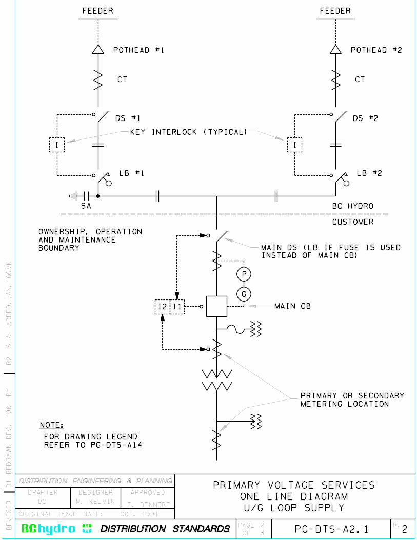
RE
VIS
ED
R.
ORIGINAL ISSUE DATE:
PAGE
OF
APPROVEDDRAFTER DESIGNER
PG-DTS-A2.1
OCT. 1991
FEEDERFEEDER
DS #1
LB #1
POTHEAD #1
DS #2
LB #2
POTHEAD #2
KEY INTERLOCK (TYPICAL)
OWNERSHIP, OPERATION
AND MAINTENANCE
BOUNDARY MAIN DS (LB IF FUSE IS USED
INSTEAD OF MAIN CB)
BC HYDRO
CUSTOMER
MAIN CB
PRIMARY OR SECONDARY
METERING LOCATION
FOR DRAWING LEGEND
REFER TO PG-DTS-A14
NOTE:
I I
P
G
R1-R
ED
RA
WN
DE
C. ’96 D
Y
CT CT
I2 I1
SA
2
32
PRIMARY VOLTAGE SERVICES
ONE LINE DIAGRAM
U/G LOOP SUPPLYDC M. KELVIN
F. DENNERT
R2- S
.A. A
DD
ED
.JA
N.’
09M
K

RE
VIS
ED
R.
ORIGINAL ISSUE DATE:
PAGE
OF
APPROVEDDRAFTER DESIGNER
DC
PG-DTS-A2.2
OCT. 1991
R1
-R
ED
RA
WN
AP
RIL
’0
1
DY
TO BC HYDRO
POTHEAD
TO LB SWITCH
C
B
A
DS SWITCH
17
FT-1
TEST SWITCH
15 13 11 9
18 16 14 12 10 8
7 35
6 4
C
B
A
N
NOTES:
1. PROVIDE SEPARATE GROUNDING CONDUCTORS FROM FT-1 TERMINAL
NUMBERS 4 AND 5 DIRECT TO GROUND BUS.
2. GROUND CT CIRCUITS ONLY AT FT-1 TEST SWITCHES, NOT AT THE CT .
3. NORMALLY 6 CTS AND 2 FT-1 TEST SWITCHES ARE REQUIRED PER CUSTOMER.
M. KELVIN
600-5A CT S
S
PRIMARY VOLTAGE SERVICES
U/G LOOP SUPPLY
TEST SWITCH WIRING DIAGRAM
3
32
F. DENNERT
R2- R
EF
ER
EN
CE
RE
VIS
ED
.JA
N.’
09M
K

RE
VIS
ED
R.
ORIGINAL ISSUE DATE:
PAGE
OF
APPROVEDDRAFTER DESIGNER
1
1
NOV. 1984
NOTE:
PG-DTS-A3
I
BC HYDRO
CUSTOMER
NORMAL
FEEDER
P
G
I I
BC HYDRO
CUSTOMER
NORMAL
FEEDER
P
G
I
I
STANDBY
FEEDER
NORMALLY OPEN
LOAD BREAK SWITCHES
PREFERRED PROTECTION
CT LOCATION
FOR DRAWING LEGEND REFER TO PG-DTS-A14
FOR KEY INTERLOCK SCHEMATIC SEE PG-DTS-A13
R1
-R
ED
RA
WN
AP
RIL
’0
1
DY TO CUSTOMER’S LOAD
2
PRIMARY VOLTAGE SERVICES
ONE LINE DIAGRAM-TYPICAL
DOUBLE DUAL RADIAL SUPPLY
SASA
DC M. KELVINF. DENNERT
R2- S
.A. A
DD
ED
.JA
N.’
09M
K

RE
VIS
ED
R.
ORIGINAL ISSUE DATE:
PAGE
OF
APPROVEDDRAFTER DESIGNER
1
1
FEB. 1986
PG-DTS-A4
R1
-R
ED
RA
WN
AP
RIL
’0
1
DY
CUSTOMER’S
GROUND O/C
RELAY
CUSTOMER’S PHASE O/C RELAY
HYDRO PHASE O/C RELAY
HYDRO GROUND O/C RELAY
HYDRO GROUND O/C RELAY
HYDRO PHASE O/C RELAY
CUSTOMER’S FUSE
TOTAL CLEARING
CHARACTERISTICS
(OR CUSTOMERS
PHASE AND GROUND
RELAY CURVES).
HYDRO 100T SERVICE FUSETIM
ET
IME
CURRENT
CURRENT
BC HYDRO SUPPLY WITH SERVICE FUSE
BC HYDRO SUPPLY WITHOUT SERVICE FUSE
2
DC M. KELVIN F. DENNERT
PRIMARY VOLTAGE SERVICES
PROTECTION COORDINATION SAMPLES
CUSTOMER SERVICES AND BC HYDRO
R2
- D
RA
WIN
G T
IT
LE
RE
VIS
ED
.JA
N.’
09
MK

R.
ORIGINAL ISSUE DATE:
PAGE
OF
APPROVEDDESIGNER
A. NORRIS
MAY 1983
DETAIL 1
F. DENNERT
DR
AF
TE
R:
DM
RECOMMENDED
A. NORRIS
0PG-DTS-A51
1
COMPLETE TERMINATOR ASSEMBLY
GROUNDING DIAGRAM
GROUND BUS
SWITCHBOARD BUS
SWITCHBOARD BUS
(FOR HOLE SIZES
SEE PG-DTS-A6)
CABLE RESTRAINT BLOCK
PRIMARY VOLTAGE SERVICES
PRIMARY XLPE SERVICE CABLES
TERMINATION DETAILS
DETAIL 1
BUNDLED CONCENTRIC
NEUTRAL WIRES
CABLE JACKET

RE
VIS
ED
R.
ORIGINAL ISSUE DATE:
PAGE
OF
APPROVEDDRAFTER DESIGNER
1
1
FEB. 1986
PG-DTS-A6
R6-R
ED
RA
WN
& R
EV
IS
ED
AP
RIL
’01 D
Y
CABLE SIZE
AND TYPE
VOLTAGE
(kV.)
CLAMP
HOLE DIA.
BUS HOLE DIMENSIONS
A B C
3/4 " 5/16 "#2 CU. 13 1 1/16 " 11/32 "
3/4 " 5/16 "13 1 3/32 " 11/32 "#1/0 AL.
9/16 "13 1 1/4 " 5/8 "#2/0 CU. 1 3/4 "
9/16 "13 1 9/32 " 5/8 "#4/0 AL. 1 3/4 "
9/16 "25 1 9/32 " 5/8 "1 3/4 "#1 AL.
9/16 "25 1 1/2 " 5/8 "#4/0 AL. 1 3/4 "
9/16 "25 1 1/2 " 5/8 "1 3/4 "500 kCM AL.
CSA LIVE PART
CLEARANCE
REQUIRED DISTANCE
FOR TERMINATIONS:
13kV. - 500mm
25Kv. - 750mm
90
0m
m M
IN
.
CL
C DUCT
CSA GROUND
CLEARANCE
C A
B
R7-C
AB
LE
SU
PP
OR
T B
EL
OW
BU
S S
EP
T. ’05 F
LK
CONCRETE SLAB
1400-1650mm
8
F. DENNERTM. KELVIN
PRIMARY VOLTAGE SERVICES
SERVICE CABLE SUPPORT BLOCKS AND
TERMINATION REQUIREMENTS
NOTE: BC HYDRO WILL NOT ACCEPT
INVERTED CABLE CONNECTIONS.
GROUNDING BALL
NEMA SPACING
DC
CUBICLE BUS OR LINE
SIDE OF SWITCH
SWITCHBOARD BUS OR
LINE SIDE OF SWITCH
FOR BOTTOM ENTRY
CABLES AND UPRIGHT
CABLE TERMINATIONS
SPLIT BLOCKS (OR CSA
APPROVED CABLE CLAMPS)
MOUNTED DIRECTLY BELOW
BUS. FOR HOLE DIAMETER
SEE TABLE
CONNECTOR ON NEUTRAL
OR GROUND BUS FOR
SERVICE NEUTRAL. SEE
SECTION 9.1.2
AB
OV
E D
UC
T C
EN
TR
E
TO
AL
LO
W F
OR
CA
BL
E
BE
ND
L
R8- R
ED
RA
WN
& R
EV
IS
ED
.JA
N.’
09M
K

LL
RE
VIS
ED
R.
ORIGINAL ISSUE DATE:
PAGE
OF
APPROVEDDRAFTER DESIGNER
3
1
APRIL 1984
SINGLE CONDUCTOR POTHEADS
THIS DRAWING IS PART OF B.C. HYDRO SPECIFICATION NO. 405-0000.
INDOOR TYPES
DIMENSIONS
VOLTAGE MAX. COND.
TOLERANCES TO BE 5.0mm EXCEPT AS NOTED
44.5 0.2
15 150 2
D2
46 1
0.280
14.0
10.0 0.5
CD1
B
1
40
110 2
135
A
E4-SLOTS AT
14mm DIA.
3/4 " OR 1" N.P.T.
FILLING PLUG
MOUNTING HOLES
WITH 3/8 " DIA. BOLTS
13kV 250 kCM 35 1 14.0 0.2 64 2 26.8 0.1 27.0 0.2 380 10
AND GROUNDING STUD.
0.0
0.0 25kV 250 kCM 35 1 14.0 0.2 64 2 26.8 0.1 27.0 0.2 425 10
+
+
51
STOCK NO. 405-0200 FOR 13kV AND
STOCK NO. 405-0210 FOR 25kV INCLUDE:
POTHEAD C/W NEMA PAD CONNECTOR
RATING SIZE A B C D1 D2 E
~~
~ ~
~ ~
~ ~
~
~
~~ ~
~~
~
~
~
~
R5
-R
ED
RA
WN
& R
EV
IS
ED
NO
V.
’9
6
DY
R6-R
EV
IS
ED
AP
RIL
. ’01 D
Y
C
THREE CONDUCTOR POTHEAD
INDOOR TYPE
DIMENSIONS
B
C
*
A
270
15
640
CL
535
194 194
+
*+
0+
ALL DIMENSIONS 5.0 mm EXCEPT AS NOTED
51
1
D
VOLTAGE MAX, COND.
3/4 " OR 1"N.P.T.FILLINGPLUGS
4-SLOTSOR HOLES14mm DIA.
FOR DETAILSEE G-UO8-C633
15
~
15KV 750 KCM 50 2 8.0 0.5 44.0 2 31.6 0.1
RATING SIZE A B C D
~
~ ~ ~
~
~
CONNECTORS FOR THREE PHASEPOTHEADS ARE ORDERED AS SEPARATE ITEMS.FOR CONNECTION DETAILSREFER TO ES53 S1-01.04.
CL
CABLEPULLPIT
1200
(MIN
.)
MOUNTING HOLESWITH 1/2 " DIA. BOLTS
PRIMARY VOLTAGE SERVICES
PRIMARY PILC SERVICE CABLE
TERMINATION DETAILS
VAULTFLOOR SLAB
7
DC M. KELVINF. DENNERT
R7
- I
NS
TA
LL
AT
IO
N D
IM
EN
SIO
NS
AD
DE
D.J
AN
. ’0
9M
K
PG-DTS-A7
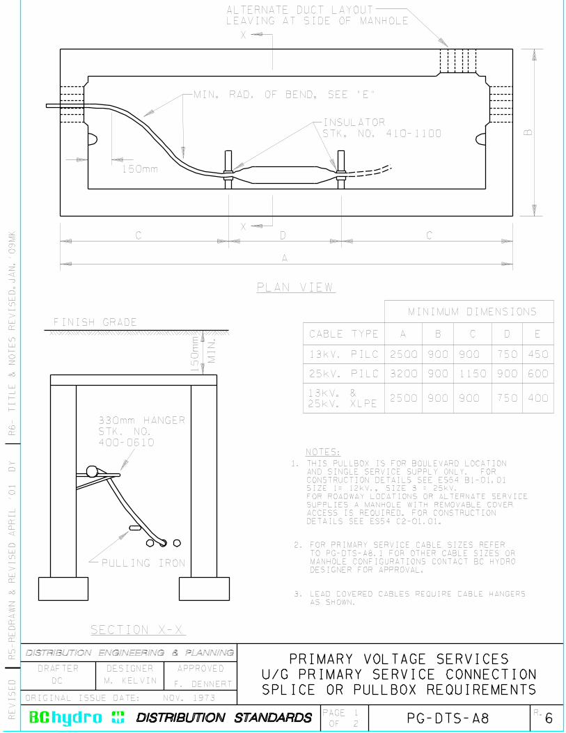
RE
VIS
ED
R.
ORIGINAL ISSUE DATE:
PAGE
OF
APPROVEDDRAFTER DESIGNER
1
NOV. 1973
PG-DTS-A8
R5-R
ED
RA
WN
& R
EV
IS
ED
AP
RIL
’01 D
Y
PLAN VIEW
SECTION X-X
ALTERNATE DUCT LAYOUT
LEAVING AT SIDE OF MANHOLE
MIN. RAD. OF BEND, SEE "E"
INSULATOR
STK. NO. 410-1100 B
D
A
C C
150mm
150m
m
MIN
.
FINISH GRADE
330mm HANGER
STK. NO.
400-0610
PULLING IRON
A B EDC
450
600
400
750
900
750
900
1150
900
900
900
900
2500
3200
2500
MINIMUM DIMENSIONS
13kV. PILC
25kV. PILC
13kV. &
25kV. XLPE
CABLE TYPE
X
X
PRIMARY VOLTAGE SERVICES
U/G PRIMARY SERVICE CONNECTION
SPLICE OR PULLBOX REQUIREMENTS
62
DC M. KELVINF. DENNERT
R6
- T
IT
LE
& N
OT
ES
RE
VIS
ED
.JA
N.’
09
MK
NOTES:
3. LEAD COVERED CABLES REQUIRE CABLE HANGERS
AS SHOWN.
1. THIS PULLBOX IS FOR BOULEVARD LOCATION
AND SINGLE SERVICE SUPPLY ONLY. FOR
CONSTRUCTION DETAILS SEE ES54 B1-01.01
SIZE 1= 12kV., SIZE 3 = 25kV.
FOR ROADWAY LOCATIONS OR ALTERNATE SERVICE
SUPPLIES A MANHOLE WITH REMOVABLE COVER
ACCESS IS REQUIRED. FOR CONSTRUCTION
DETAILS SEE ES54 C2-01.01.
2. FOR PRIMARY SERVICE CABLE SIZES REFER
TO PG-DTS-A8.1 FOR OTHER CABLE SIZES OR
MANHOLE CONFIGURATIONS CONTACT BC HYDRO
DESIGNER FOR APPROVAL.

R.
ORIGINAL ISSUE DATE:
PAGE
OF
APPROVEDDESIGNER
2
1
1
1
1500
1000
2000
2500
3000
1
1
1
#1
12.5kV Unit Substations
Underground Supply Dip from O/H Supply
4000
#1
#1
#1#1
4/0
1 500 kcm5000
4/0
1500
1000
2000
2500
3000
Underground Supply Dip from O/H Supply
4000
5000
25kV Unit Substations
DR
AF
TE
R:
DM
RECOMMENDED
F. DENNERT
Unit Substation
kVA Size
Unit Substation
kVA Size
Cables
per Phase
Size of
Al. Cond.
1
1
1
1
1
1
#1
#1
4/0
1
Cables
per Phase
Size of
Al. Cond.
4/0
4/0
500 kcm
N/A
1
1
1
1
1
1
#1
#1
#1
#1#1
1
Cables
per Phase
Size of
Al. Cond.
1
1
1
1
1
1
#1
#1
1
Cables
per Phase
Size of
Al. Cond.
4/0
#1
#1
#1
#1
#1
#1
4/0
FEBRUARY 1981
PG-DTS-A8.1 02
PRIMARY VOTLAGE SERVICES
CUSTOMER OWNED SERVICE EQUIPMENT
BC HYDRO PRIMARY CABLE SPLICES
RECOMMENDED SIZE OF PRIMARY SERVICE CABLES
NOTE: For primary XLPE service cable connection details refer to ES53-S3-01.
A. JACOBA. JACOB

R.
ORIGINAL ISSUE DATE:
PAGE
OF
APPROVEDDESIGNER
DR
AF
TE
R:
JM
W
F.DENNERT
RECOMMENDED
11
R1
- E
DIT
OR
IA
L N
OT
ES
.JA
N.’
09
MK
PG-DTS-A9
PRIMARY VOLTAGE SERVICES
PRIMARY VAULT BELOW GRADE
WALL CABLE ENTRY & PULL PIT DETAIL
1.5
2.0 MIN.
A A
3 - 4" DUCTS
CONC. ENC.
CHECKER PLATE COVERS
WITH DROP DOWN HANDLES
REMOVABLE METAL CABLE GUARD
DISC
& L.B.
SWITCH
DISC
& L.B.
SWITCH
CABLE TERMINATION
COMPARTMENTS
NOTE:
PLAN
PULL PIT
PULL PIT DRAIN CONNECTED
TO BUILDING DRAIN
SECTION A-A
T-DRAIN TO
BUILDING DRAIN
1.0 MIN. RADIUS
RIGID STEEL
(THREADED)
REMOVABLE METAL
CABLE GUARD
CHECKER PLATE
COVERS WITH DROP
HANDLES
FINISHED GRADE
3-4" DUCTS
CONC. ENC.
0.9
1 M
IN
.C
OV
ER 2.0 MIN.
1.5
MIN
.
PULL PIT
1.0
1.0
DE
EP
PIT
VAULT FLOOR SLAB
NOVEMBER 2006
2
DB2 DOWELLED
IN REBAR CONC.
ENCS’D.
NOTE: For further notes and installation details see ES54 S3-01.01 through S3-03.04
- PLATES TO BE 50lbs EA.
- 80lbs EA. IF HINGED.
- 0.9m x 0.9m ACCESS PLATE MIN.
PULLING IRON
SUPPLIED BY
BCHYDRO, INSTALLED
BY GENERAL CONTRACTOR
(TYP. FOR 2)
PULLING IRON
‘
M.KELVINM.KELVIN

R.
ORIGINAL ISSUE DATE:
PAGE
OF
APPROVEDDESIGNER
DR
AF
TE
R:
JM
W
F.DENNERT
RECOMMENDED
1
R1
- E
DIT
OR
IA
L N
OT
ES
.JA
N.’
09
MK
PG-DTS-A9.1
PRIMARY VOLTAGE SERVICES
OUTDOOR PRIMARY SERVICE KIOSK
CONCRETE SLAB & CABLE PULLING DETAILS
OPERATING
CLEARANCE
3.0m MIN.
CUSTOMER OWNED PULL BOX
(SEE NOTE 3 & 7)
CONCRETE PAD
(SEE NOTE 4)
CUSTOMER
PRIMARY
SERVICE
KIOSK
CROSS SECTION
FRONT
(SEE NOTE 5)
CUSTOMER PRIMARY
SERVICE
1.6
m M
IN
.
500
(APPROX.)
3.0m
CUSTOMER OWNED
PULL BOX
(SEE NOTE 3)
0.91m(MIN.)
DRAIN ROCK
600200
100
NOTES:
PLAN VIEW
NOVEMBER 2006
2
2
1. Meters expressed in decimals.
2. Millimetres in whole numbers.
3. For dimensions of customer
owned pullbox, see PG-DTS-A8.
4. Primary service kiosk to be
located per CEC rules.
5. BCH will not operate customer
primary service switches.
6. For further installation details,
see ES54 S3-01.01 through S3-01.04.
7. Exact location of pullbox must be
approved by BC Hydro designer.
M. KELVIN M. KELVIN

R.
ORIGINAL ISSUE DATE:
PAGE
OF
APPROVEDDESIGNER
DECEMBER 1979
DR
AF
TE
R:
JM
W
A.NORRIS
F.DENNERT
RECOMMENDED
A.NORRIS
PRIMARY VOLTAGE SERVICES
U/G SERVICE CABLE PULLBOX AND
DEMARCATION STRUCTURE
PG-DTS-A9.2 11
1
R1
- E
DIT
OR
IA
L N
OT
ES
.JA
N.’
09
MK
NOTE:
FOR EXACT DESCRIPTION
AND INSTALLATION DETAILS,
REFER TO BCH STANDARD
ES-53 D4-01.
A A
B
B
C-CHANNEL
CONCRETE
INSERT
SECTION B-B
SECTION A-A
PLAN VIEW
832
PRECAST
CONCRETE
VAULT
GRADE
GRADE

RE
VIS
ED
R.
ORIGINAL ISSUE DATE:
PAGE
OF
APPROVEDDRAFTER DESIGNER
1
1
NOV. 1984
PG-DTS-A10
R5-R
ED
RA
WN
& R
EV
IS
ED
AP
RIL
’01 D
Y
2
1 3
1
2 3
2
13
1
23
4
TO METERING COMPARTMENT
PRIMARY VOLTAGE SERVICES
DUAL RADIAL SUPPLY SWITCHBOARD
SERVICE ENTRANCE CELL DETAILS
6
DC M. KELVINF. DENNERT
R6- E
DIT
ED
& R
ED
RA
WN
.JA
N.’
09M
K
NOTE:
NOTES:
FOR DRAWING LEGEND REFER TO PG-DTS-A14
1
2
3
4 -POWER FUSE OR CIRCUIT BREAKER.
-AIR OPENING (REFER TO PARAGRAPH 9.5.6).
-BOLTED BUS BAR SECTION AS PER PARAGRAPH 9.1.4. CLAUSE.
-SHEET METAL BARRIERS (IN PLACE WHEN BUS SECTION IS DISMANTLED).
-FOR INTERLOCKING BETWEEN LOAD-BREAK SELECTOR SWITCH,
DISCONNECT SWITCH AND CUSTOMER’S POWER FUSE OR CIRCUIT BREAKER.
REFER TO PG-DTS-A11.
-FOR GENERAL SWITCHBOARD REQUIREMENTS REFER TO SECTION 9.3. OF
PRIMARY GUIDE.

RE
VIS
ED
R.
ORIGINAL ISSUE DATE:
PAGE
OF
APPROVEDDRAFTER DESIGNER
1
1
NOV. 1984
PG-DTS-A11
K1
K1
K2
K2
K1
K1
K2
K2
R2-R
ED
RA
WN
& R
EV
IS
ED
AP
RIL
’01 D
Y
(FUSE COMPARTMENT
ACCESS DOOR)
(PRIMARY METERING
COMPARTMENT
ACCESS DOORS)
M. KELVINF. DENNERT
PRIMARY VOLTAGE SERVICES
DUAL RADIAL SUPPLY SWITCHBOARD
TWO KEY INTERLOCK
3
DC
R3- T
IT
LE
RE
VIS
ED
.JA
N.’
09M
K
NOTE:
KEY SEQUENCE:
3. THE KEY FROM THE RESPECTIVE LOAD-BREAK SELECTOR SWITCH IS REQUIRED
TO OPERATE THE DISCONNECT SWITCH, OPEN OR CLOSE. THE KEY IS
REMOVABLE FROM THE DISCONNECT SWITCH IN EITHER POSITION.
PURPOSE OF THE INTERLOCK SYSTEM
1. ALLOWS MOMENTARILY PARALLELING OF THE TWO INCOMING CIRCUITS DURING
TRANSFER OF SERVICE CIRCUIT.
2. PREVENTS OPENING THE DISCONNECT SWITCHES UNDER LOAD.
3. ALLOWS OPERATION OF THE LOAD-BREAK SWITCH WHEN IT HAS BEEN ISOLATED
FOR SERVICE REASONS.
FOR DRAWING LEGEND REFER TO PG-DTS-A14
1. ONLY TWO INDIVIDUAL KEYS K1 AND K2 ARE PROVIDED.
2. KEYS K1 AND K2 ARE HELD CAPTIVE WHEN THEIR RESPECTIVE LOAD-BREAK
SELECTOR SWITCHES ARE IN THE CLOSED POSITION. THEY CAN BE
RELEASED ONLY WHEN THE LOAD-BREAK SELECTOR SWITCH IS LOCKED
IN THE OPEN POSITION.
4. PREVENTS ACCESS INTO THE FUSE CELL OR PRIMARY METERING COMPARTMENT
WITHOUT FIRST OPENING BOTH LOAD-BREAK SWITCHES.
4. BOTH KEYS K1 AND K2 ARE REQUIRED TO OPEN EITHER THE FUSE COMPARTMENT
DOOR OR THE PRIMARY METERING COMPARTMENT DOOR. THE KEYS ARE HELD
CAPTIVE WHEN THE DOOR IS IN THE OPEN POSITION. (ONLY ONE DOOR CAN
BE OPENED AT A TIME).

RE
VIS
ED
R.
ORIGINAL ISSUE DATE:
PAGE
OF
APPROVEDDRAFTER DESIGNER
1
1
NOV. 1984
PG-DTS-A12
R2-R
ED
RA
WN
& R
EV
IS
ED
AP
RIL
’01 D
Y
4
2
3
1
4
2
3
1
2
3
1
1
2 3
1
2 32 3 2 3
1
TO METERING
COMPARTMENT
TO METERING
COMPARTMENT
PRIMARY VOLTAGE SERVICES
DOUBLE DUAL RADIAL SUPPLY
SERVICE ENTRANCE SWITCHBOARD
3
DC M. KELVINF. DENNERT
R3
- T
IT
LE
& N
OT
ES
RE
VIS
ED
.JA
N.’
09
MK
NOTE:
NOTES:
FOR DRAWING LEGEND REFER TO PG-DTS-A14
1
2
3
4 -POWER FUSE OR CIRCUIT BREAKER.
-BOLTED BUS LINKS.
-FOR GENERAL SWITCHBOARD REQUIREMENTS REFER TO SECTION 9.4.
OF PRIMARY GUIDE.
-AIR OPENING REFER TO PARAGRAPH 9.5.6.
-SHEET METAL BARRIERS (IN PLACE WHEN BUS LINKS ARE DISMANTLED).
-FOR INTERLOCKING BETWEEN LOAD-BREAK SELECTOR SWITCH, DISCONNECT
SWITCH AND BC HYDRO METERING COMPARTMENT, REFER TO PG-DTS-A13.

RE
VIS
ED
R.
ORIGINAL ISSUE DATE:
PAGE
OF
APPROVEDDRAFTER DESIGNER
1
1
NOV. 1984
PG-DTS-A13
A1
R1-R
ED
RA
WN
& R
EV
IS
ED
AP
RIL
’01 D
YNORMAL
CCT. #1
NORMAL
CCT. #2
K1
A2 K1
K1
K4
M1
LOAD "X" LOAD "Y"
K4 K5
K2
K2
K3
K3
B1
B2
C1
C2
DI N.O. D2 N.O.
K3
K5
M2
METERING
COMPARTMENT
LOAD-BREAK SWITCH
(BOTH TO BE PADLOCKED
BY BC HYDRO)
STANDBY
CCT.
DC M. KELVINF. DENNERT
PRIMARY VOLTAGE SERVICES
DOUBLE DUAL RADIAL SERVICE
FIVE KEY INTERLOCK
2
R2- T
IT
LE
RE
VIS
ED
.JA
N.’
09M
K
NOTE:
FOR DRAWING LEGEND REFER TO PG-DTS-A14
1. ALLOWS MOMENTARY PARALLELING OF EITHER OF THE NORMAL CIRCUITS
WITH THE STANDBY DURING LOAD TRANSFER.
PURPOSE OF KEY INTERLOCK SYSTEM
2. PREVENTS OPERATION OF DISCONNECT SWITCHES AND ACCESS TO CIRCUIT
BREAKER OR METERING COMPARTMENT UNDER LOAD. (KEYS K1, K2, K3,
K4 AND K5 ARE HELD CAPTIVE WHEN USED FOR CLOSING THEIR RESPECTIVE
LOAD-BREAK SWITCHES AND DISCONNECT SWITCHES OR OPENING THE
METERING COMPARTMENT DOORS).
KEY INTERLOCK SEQUENCE:
(FIVE INDIVIDUAL KEYS K1, K2, K3, K4 AND K5 ARE PROVIDED)
I. ACCESS TO BC HYDRO METERING COMPARTMENT M1:
OPEN LOAD-BREAK SWITCHES A2 AND B2, THUS RELEASING KEYS K1 AND K2.
OPEN DISCONNECTS A1 AND B1 WITH K1 AND K2 FOR POSITIVE ISOLATION.
RETRIEVE K4 FROM D1 WHICH IS NORMALLY OPEN. THEN OPEN BC HYDRO
METERING COMPARTMENT M1 WITH K1 AND K4. SIMILAR PROCEDURES APPLY
WHEN ACCESS TO METERING COMPARTMENT M2 IS REQUIRED.
II. TO FEED LOAD "X" BY NORMAL CIRCUIT #1:
ENSURE B1, B2 AND D1 AND D2 ARE OPEN. REMOVE KEY K1 FROM METERING
COMPARTMENT M1. WITH KEY K1, CLOSE DISCONNECT A1 AND CLOSE CIRCUIT
TO FEED LOAD LOAD "X" BY CLOSING LOAD-BREAK SWITCH A2. SIMILAR
PROCEDURE APPLIES WHEN FEEDING LOAD "Y" BY NORMAL CIRCUIT #2.
III. TO TRANSFER LOAD "X" FROM NORMAL CIRCUIT #1 TO STANDBY:
ENSURE D1, D2 AND B1, B2 ARE OPEN. CLOSE LOAD-BREAK D1 (K4 WILL
BE HELD CAPTIVE). WITH KEY K2 CLOSE B1. MOMENTARILY PARALLEL
NORMAL CIRCUIT #1 WITH STANDBY CIRCUIT BY CLOSING B2 WITH KEY 2.
OPEN LOAD-BREAK A2, THUS RELEASING KEY K1. OPEN DISCONNECT A1 FOR
POSITIVE ISOLATION. LOAD "X" IS NOW TRANSFERRED TO STANDBY CIRCUIT.
SIMILAR PROCEDURE APPLIES WHEN TRANSFERRING LOAD "Y" FROM NORMAL
CIRCUIT #2 TO STANBY.

RE
VIS
ED
R.
ORIGINAL ISSUE DATE:
PAGE
OF
APPROVEDDRAFTER DESIGNER
1
1
NOV. 1984
P
G
I
FUSED DISCONNECT
SWITCH
BC HYDRO
METERING
TRANSFORMERS
GANG-OPERATED
LOAD-BREAK
SELECTOR SWITCH
GANG-OPERATED
DISCONNECT SWITCH
FUSE
POWER CIRCUIT BREAKER
OR APPROVED SINGLE
SHOT CIRCUIT RECLOSER
KEY INTERLOCK
BC HYDRO CABLE
TERMINATION
POWER CIRCUIT
OVERCURRENT
PHASE RELAY
OVERCURRENT
GROUND RELAY
PROTECTION AND
METERING CIRCUIT
KEY INTERLOCKING
CONNECTION
MOTORIZED GANG-OPERATED
LOAD-BREAK SWITCH
PG-DTS-A14
R1
-R
ED
RA
WN
AP
RIL
’0
1
DY
BOLTED BUSBAR
SECTION
DC M. KELVIN F. DENNERT
PRIMARY VOLTAGE SERVICES
DRAFTING LEGEND
2
R2- T
IT
LE
RE
VIS
ED
.JA
N.’
09M
K

Last revised: 11 June 2002
td-stateprimvoltequip.doc Sheet 1 of 2
Statement to BC Hydro Regarding Primary Voltage Service Entrance Equipment The Customer, or representative, provides this Statement to BC Hydro knowing that BC Hydro intends to rely upon it.
BC Hydro may refuse to supply Electricity to the Customer or suspend or discontinue the supply if, in BC Hydro’s judgment, the Equipment is not compatible with or suitable for the BC Hydro electrical system.
The judgment by BC Hydro of the Equipment shall not be construed by the Customer or others as an endorsement of the design or as a warranty by BC Hydro of the Equipment for the purpose of the Customer or others than BC Hydro.
Project Location Owner/Developer
Service: U/G O/H At kV Expected Service Date:
Type of Service Equipment: O/H Structure Unit Sub. Outdoor Indoor Vault
Required Drawings: One-Line Drawing Number Site Plan Drawing Number
Equipment Layout Drawing Number
Transformers: Bank kV•A H.V. Winding L.V. Winding High Voltage Taps On-load Impedance
Volts ∆ Y Y Volts ∆ Y Y Above Rated
Volt.
Below Rated Volt. Tap %
Grounded Grounded No. % No. % Changer on bank
± % kV•A base
(ONAN)
Service Entrance: (Complete I or II) (I) Circuit Breaker:
Voltage Rating Current Rating Interrupting Rating Clearing Time Trip Coil - Current Trip Amps (ac)
kV Amps KA SYM RMS Cycles - or Shunt Trip Volts (dc)
(II) Fuse Protection: Either Load Break Switch, or Disconnect Switch Interlocked with Secondary Breaker. (A) Switch (Specify Mounting): Pole Structure Cubicle
Voltage Rating Load Interrupting Rating At Momentary Rating At Manufacturer (if known) CSA Approval
kV Amps % P.F. Amps % P.F. Yes No.
(B) Fusing
Manufacturer Manufacturer Type Designation Rated Continuous Current Rated Maximum Voltage Fuse Characteristics
Interconnection Protection:
Protection Manufacturer Type/Style Timed Element Setting Range
Inst. Element Setting Range
Ground Overcurrent
Phase Overcurrent
Over Under Voltage
Over Under Frequency
Synchronizing Check
Reverse Power
Differential
Under Frequency Load Shedding
Are C.T.’s adequate to operate relays and current trip coils where applicable for all current magnitude from minimum trip to maximum fault duty?
Yes No based on maximum fault duty of MV•A

- 2 -
Last revised: 11 June 2002
td-stateprimvoltequip.doc Sheet 2 of 2
Metering:
Pole Metering. Yes No Estimated Maximum Demand Metered Voltage
Vault or Indoor Unit Sub. Yes No Initial Future
Outdoor or Unit Sub Yes No Rate Schedule
kW kW
Customer Generation: No Customer generation.
Customer generation not parallel to BC Hydro supply, transfer switch type:
Customer generation parallel to BC Hydro supply but with no agreement to sell electricity to BC Hydro. If selected,
Customer generation parallel to BC Hydro supply with intent to sell electricity to BC. Hydro. complete Generators Section.
Generators:
Type Energy Manufacturer Rated Output
Rated Output Power
3 PH or
Total Harmonic Content
Reactance in % Machine kV•A Base
Machine Inertia
Source in kW Voltage Factor 1 PH Current Voltage Xd Xd’ Xd’’ Constant H
1. Hydraulic 2. Gas 3. Woodwaste 4. Diesel 5. Other: If the above space is insufficient for all
1. Synchronous Generator 2. Induction Generator 3. Other: generators, please provide remaining generator information separately.
Seal of Professional Engineer BC Hydro
Company
Signature Received By
Date Date

RE
VIS
ED
R.
ORIGINAL ISSUE DATE:
PAGE
OF
APPROVEDDRAFTER DESIGNER
1
1
MARCH 1972
PG-DTS-B1
R1
-R
ED
RA
WN
AP
RIL
’0
1
DY
CURRENT IN AMPERES
TIM
E I
N S
EC
ON
DS
.01
.1
1
10
100
1000
10
00
10
00
0
10
0
10
20
30
40
50
60
70
80
90
20
0
30
0
40
0
50
0
60
0
70
0
80
0
90
0
2000
3000
4000
5000
6000
7000
8000
9000
.02
.03
.04
.05
.06
.07
.08
.09
.2
.3
.4
.5
.6
.7
.8
.9
2
3
4
5
6
7
8
9
20
30
40
50
60
70
80
90
200
300
400
500
600
700
800900
140T 200T
100T65T40T25T15T10T6TAMPERE RATING
PRIMARY VOLTAGE SERVICES
TIME-CURRENT FUSE CURVES
TYPE T FUSE CHARACTERISTICS
2
DC M. KELVINF. DENNERT
R2
- T
IT
LE
RE
VIS
ED
.JA
N.’
09
MK
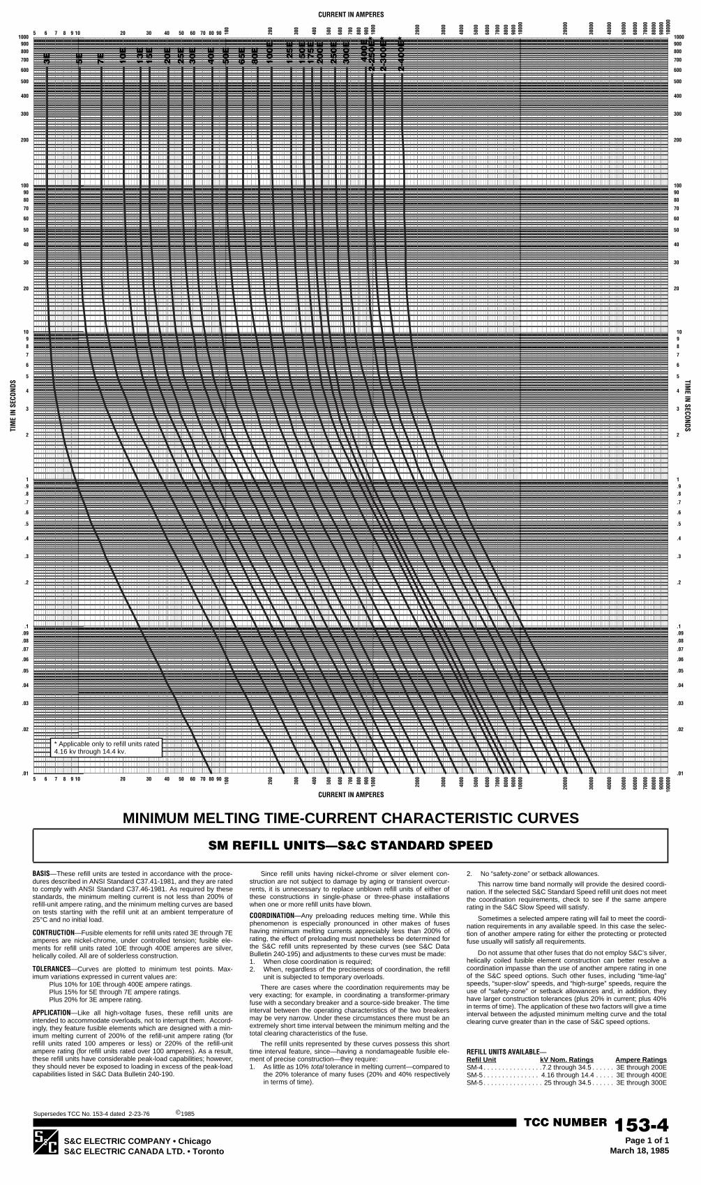
S&C ELECTRIC COMPANY • ChicagoS&C ELECTRIC CANADA LTD. • Toronto
TCC NUMBER
153-4
Page 1 of 1March 18, 1985
Supersedes TCC No. 153-4 dated 2-23-76
c
1985
s
1000900800
400
700
600
500
300
200
1000900800
400
700
600
500
300
200
TIM
E IN
SEC
ONDS
1009080
40
70
60
50
30
20
1009080
40
70
60
50
30
20
1098
4
7
6
5
3
2
1098
4
7
6
5
3
2
1.9.8
.4
.7
.6
.5
.3
.2
1.9.8
.4
.7
.6
.5
.3
.2
.1.09.08
.04
.07
.06
.05
.03
.02
.1
.09
.08
.04
.07
.06
.05
.03
.02
1000
0090
000
8000
0
4000
0
7000
0
6000
0
5000
0
3000
0
2000
0
1000
090
0080
00
4000
7000
6000
5000
3000
2000
1000
900
800
400
700
600
500
300
200
100
908040 70605030201098765
.01 .01
CURRENT IN AMPERES
1000
0090
000
8000
0
4000
0
7000
0
6000
0
5000
0
3000
0
2000
0
1000
090
0080
00
4000
7000
6000
5000
3000
2000
100090
080
0
400
700
600
500
300
200
100908040 70605030201098765
TIME IN SECONDS
CURRENT IN AMPERES
BASIS
—These refill units are tested in accordance with the proce-dures described in ANSI Standard C37.41-1981, and they are ratedto comply with ANSI Standard C37.46-1981. As required by thesestandards, the minimum melting current is not less than 200% ofrefill-unit ampere rating, and the minimum melting curves are basedon tests starting with the refill unit at an ambient temperature of25°C and no initial load.
CONTRUCTION
—Fusible elements for refill units rated 3E through 7Eamperes are nickel-chrome, under controlled tension; fusible ele-ments for refill units rated 10E through 400E amperes are silver,helically coiled. All are of solderless construction.
TOLERANCES
—Curves are plotted to minimum test points. Max-imum variations expressed in current values are:
Plus 10% for 10E through 400E ampere ratings.Plus 15% for 5E through 7E ampere ratings.Plus 20% for 3E ampere rating.
APPLICATION
—Like all high-voltage fuses, these refill units areintended to accommodate overloads, not to interrupt them. Accord-ingly, they feature fusible elements which are designed with a min-imum melting current of 200% of the refill-unit ampere rating (forrefill units rated 100 amperes or less) or 220% of the refill-unitampere rating (for refill units rated over 100 amperes). As a result,these refill units have considerable peak-load capabilities; however,they should never be exposed to loading in excess of the peak-loadcapabilities listed in S&C Data Bulletin 240-190.
Since refill units having nickel-chrome or silver element con-struction are not subject to damage by aging or transient overcur-rents, it is unnecessary to replace unblown refill units of either ofthese constructions in single-phase or three-phase installationswhen one or more refill units have blown.
COORDINATION
—Any preloading reduces melting time. While thisphenomenon is especially pronounced in other makes of fuseshaving minimum melting currents appreciably less than 200% ofrating, the effect of preloading must nonetheless be determined forthe S&C refill units represented by these curves (see S&C DataBulletin 240-195) and adjustments to these curves must be made:1. When close coordination is required;2. When, regardless of the preciseness of coordination, the refill
unit is subjected to temporary overloads.
There are cases where the coordination requirements may bevery exacting; for example, in coordinating a transformer-primaryfuse with a secondary breaker and a source-side breaker. The timeinterval between the operating characteristics of the two breakersmay be very narrow. Under these circumstances there must be anextremely short time interval between the minimum melting and thetotal clearing characteristics of the fuse.
The refill units represented by these curves possess this shorttime interval feature, since—having a nondamageable fusible ele-ment of precise construction—they require:1. As little as 10%
total
tolerance in melting current—compared tothe 20% tolerance of many fuses (20% and 40% respectivelyin terms of time).
2. No “safety-zone” or setback allowances.
This narrow time band normally will provide the desired coordi-nation. If the selected S&C Standard Speed refill unit does not meetthe coordination requirements, check to see if the same ampererating in the S&C Slow Speed will satisfy.
Sometimes a selected ampere rating will fail to meet the coordi-nation requirements in any available speed. In this case the selec-tion of another ampere rating for either the protecting or protectedfuse usually will satisfy all requirements.
Do not assume that other fuses that do not employ S&C’s silver,helically coiled fusible element construction can better resolve acoordination impasse than the use of another ampere rating in oneof the S&C speed options. Such other fuses, including “time-lag”speeds, “super-slow” speeds, and “high-surge” speeds, require theuse of “safety-zone” or setback allowances and, in addition, theyhave larger construction tolerances (plus 20% in current; plus 40%in terms of time). The application of these two factors will give a timeinterval between the adjusted minimum melting curve and the totalclearing curve greater than in the case of S&C speed options.
REFILL UNITS AVAILABLE
—
Refil Unit kV Nom. Ratings Ampere Ratings
SM-4 . . . . . . . . . . . . . . . .7.2 through 34.5 . . . . . . 3E through 200ESM-5 . . . . . . . . . . . . . . . 4.16 through 14.4 . . . . . 3E through 400ESM-5 . . . . . . . . . . . . . . . . 25 through 34.5 . . . . . . 3E through 300E
MINIMUM MELTING TIME-CURRENT CHARACTERISTIC CURVES
SM REFILL UNITS—S&C STANDARD SPEED
3E
65
E
20
0E
5E
7E
10
E
20
E
15
E1
3E
25
E
50
E
40
E
30
E
80
E
15
0E
12
5E
10
0E
17
5E
40
0E
30
0E
25
0E
2-4
00
E*
2-3
00
E*
2-2
50
E*
* Applicable only to refill units rated4.16 kv through 14.4 kv.

S&C ELECTRIC COMPANY • ChicagoS&C ELECTRIC CANADA LTD. • Toronto
TCC NUMBER
153-4-2
Page 1 of 1March 18, 1985
Supersedes TCC No. 153-4-2 dated 2-23-76
c
1985
s
1000900800
400
700
600
500
300
200
1000900800
400
700
600
500
300
200
TIM
E IN
SEC
ONDS
1009080
40
70
60
50
30
20
1009080
40
70
60
50
30
20
1098
4
7
6
5
3
2
1098
4
7
6
5
3
2
1.9.8
.4
.7
.6
.5
.3
.2
1.9.8
.4
.7
.6
.5
.3
.2
.1.09.08
.04
.07
.06
.05
.03
.02
.1
.09
.08
.04
.07
.06
.05
.03
.02
1000
0090
000
8000
0
4000
0
7000
0
6000
0
5000
0
3000
0
2000
0
1000
090
0080
00
4000
7000
6000
5000
3000
2000
1000
900
800
400
700
600
500
300
200
100
908040 70605030201098765
.01 .01
CURRENT IN AMPERES
1000
0090
000
8000
0
4000
0
7000
0
6000
0
5000
0
3000
0
2000
0
1000
090
0080
00
4000
7000
6000
5000
3000
2000
100090
080
0
400
700
600
500
300
200
100908040 70605030201098765
TIME IN SECONDS
CURRENT IN AMPERES
BASIS
—These refill units are tested in accordance with the proce-dures described in ANSI Standard C37.41-1981, and they are ratedto comply with ANSI Standard C37.46-1981. As required by thesestandards, the minimum melting current is not less than 200% ofrefill-unit ampere rating, and the minimum melting and total clearingcurves are based on tests starting with the refill unit at an ambienttemperature of 25°C and no initial load.
CONSTRUCTION
—Fusible elements for refill units rated 3E through7E amperes are nickel-chrome, under controlled tension; fusibleelements for refill units rated 10E through 400E amperes are silver,helically coiled. All are of solderless construction.
TOLERANCES
—Curves are plotted to maximum test points. All varia-tions are minus.
APPLICATION
—Like all high-voltage fuses, these refill units areintended to accommodate overloads, not to interrupt them. Accord-ingly, they feature fusible elements which are designed with a min-imum melting current of 200% of the refill-unit ampere rating (forrefill units rated 100 amperes or less) or 220% of the refill-unitampere rating (for refill units rated over 100 amperes). As a result,these refill units have considerable peak-load capabilities; however,they should never be exposed to loading in excess of the peak-loadcapabilities listed in S&C Data Bulletin 240-190.
Since refill units having nickel-chrome or silver element con-struction are not subject to damage by aging or transient overcur-rents, it is unnecessary to replace unblown refill units of either of
these constructions in single-phase or three-phase installationswhen one or more refill units have blown.
COORDINATION
—These curves represent the total time required fora refill unit to melt and interrupt a fault current, and should be fol-lowed in coordination problems where fuses are applied as “pro-tecting” devices.
Any preloading reduces melting time. With respect to the “pro-tected” fuse, the effect of preloading must be determined andadjustments made to its minimum melting curve: 1. When close coordination is required;2. When, regardless of the preciseness of coordination, the pro-
tected fuse is subjected to temporary overloads.
There are cases where the coordination requirements may bevery exacting; for example, in coordinating a transformer-primaryfuse with a secondary breaker and a source-side breaker. The timeinterval between the operating characteristics of the two breakersmay be very narrow. Under these circumstances there must be anextremely short time interval between the minimum melting and thetotal clearing characteristics of the fuse.
The refill units represented by these curves possess this shorttime interval feature, since—having a nondamageable fusible ele-ment of precise construction—they require:1. As little as 10%
total
tolerance in melting current—compared tothe 20% tolerance of many fuses (20% and 40% respectivelyin terms of time).
2. No “safety-zone” or setback allowances.
This narrow time band normally will provide the desired coordi-nation. If the selected S&C Standard Speed refill unit does not meetthe coordination requirements, the selection of another ampererating for either the protecting or protected fuse usually will satisfy.
Do not assume that other fuses that do not employ S&C’s silver,helically coiled fusible element construction can better resolve acoordination impasse than the use of another ampere rating in oneof the S&C speed options. Such other fuses, including “time-lag”speeds, “super-slow” speeds, and “high-surge” speeds, require theuse of “safety-zone” or setback allowances and, in addition, theyhave larger construction tolerances (plus 20% in current; plus 40%in terms of time). The application of these two factors will give a timeinterval between the adjusted minimum melting curve and the totalclearing curve greater than in the case of S&C speed options.
REFILL UNITS AVAILABLE
—
Refill Unit kV Nom. Ratings Ampere Ratings
SM-4 . . . . . . . . . . . . . . . . . 7.2 and 14.4 . . . . . . . 3E through 200ESM-5 . . . . . . . . . . . . . . . 4.16 through 14.4 . . . . . 3E through 400E
TOTAL CLEARING TIME-CURRENT CHARACTERISTIC CURVES
SM REFILL UNITS—S&C STANDARD SPEED
3E
65
E
20
0E
5E
7E
10
E
20
E
15
E1
3E
25
E
50
E
40
E
30
E
80
E
15
0E
12
5E
10
0E
17
5E
40
0E
30
0E
25
0E
2-4
00
E
2-3
00
E
2-2
50
E

S&C ELECTRIC COMPANY • ChicagoS&C ELECTRIC CANADA LTD. • Toronto
TCC NUMBER
153-4-4
Page 1 of 1March 18, 1985
Supersedes TCC No. 153-4-4 dated 2-23-76
©
1985
1000900800
400
700
600
500
300
200
1000900800
400
700
600
500
300
200
TIM
E IN
SEC
ONDS
1009080
40
70
60
50
30
20
1009080
40
70
60
50
30
20
1098
4
7
6
5
3
2
1098
4
7
6
5
3
2
1.9.8
.4
.7
.6
.5
.3
.2
1.9.8
.4
.7
.6
.5
.3
.2
.1.09.08
.04
.07
.06
.05
.03
.02
.1
.09
.08
.04
.07
.06
.05
.03
.02
1000
0090
000
8000
0
4000
0
7000
0
6000
0
5000
0
3000
0
2000
0
1000
090
0080
00
4000
7000
6000
5000
3000
2000
1000
900
800
400
700
600
500
300
200
100
908040 70605030201098765
.01 .01
CURRENT IN AMPERES
1000
0090
000
8000
0
4000
0
7000
0
6000
0
5000
0
3000
0
2000
0
1000
090
0080
00
4000
7000
6000
5000
3000
2000
100090
080
0
400
700
600
500
300
200
100908040 70605030201098765
TIME IN SECONDS
CURRENT IN AMPERES
BASIS
—These refill units are tested in accordance with the proce-dures described in ANSI Standard C37.41-1981, and they are ratedto comply with ANSI Standard C37.46-1981. As required by thesestandards, the minimum melting current is not less than 200% ofrefill-unit ampere rating, and the minimum melting and total clearingcurves are based on tests starting with the refill unit at an ambienttemperature of 25°C and no initial load.
CONSTRUCTION
—Fusible elements for refill units rated 3E through7E amperes are nickel-chrome, under controlled tension; fusibleelements for refill units rated 10E through 300E amperes are silver,helically coiled. All are of solderless construction.
TOLERANCES
—Curves are plotted to maximum test points. All varia-tions are minus.
APPLICATION
—Like all high-voltage fuses, these refill units areintended to accommodate overloads, not to interrupt them. Accord-ingly, they feature fusible elements which are designed with a min-imum melting current of 200% of the refill-unit ampere rating (forrefill units rated 100 amperes or less) or 220% of the refill-unitampere rating (for refill units rated over 100 amperes). As a result,these refill units have considerable peak-load capabilities; however,they should never be exposed to loading in excess of the peak-loadcapabilities listed in S&C Data Bulletin 210-190.
Since refill units having nickel-chrome or silver element con-struction are not subject to damage by aging or transient overcur-rents, it is unnecessary to replace unblown refill units of either of
these constructions in single-phase or three-phase installationswhen one or more refill units have blown.
COORDINATION
—These curves represent the total time required fora refill unit to melt and interrupt a fault current, and should be fol-lowed in coordination problems where fuses are applied as “pro-tecting” devices.
Any preloading reduces melting time. With respect to the “pro-tected” fuse, the effect of preloading must be determined andadjustments made to its minimum melting curve: 1. When close coordination is required;2. When, regardless of the preciseness of coordination, the pro-
tected fuse is subjected to temporary overloads.
There are cases where the coordination requirements may bevery exacting; for example, in coordinating a transformer-primaryfuse with a secondary breaker and a source-side breaker. The timeinterval between the operating characteristics of the two breakersmay be very narrow. Under these circumstances there must be anextremely short time interval between the minimum melting and thetotal clearing characteristics of the fuse.
The refill units represented by these curves possess this shorttime interval feature, since—having a nondamageable fusible ele-ment of precise construction—they require:1. As little as 10%
total
tolerance in melting current—compared tothe 20% tolerance of many fuses (20% and 40% respectivelyin terms of time).
2. No “safety-zone” or setback allowances.
This narrow time band normally will provide the desired coordi-nation. If the selected S&C Standard Speed refill unit does not meetthe coordination requirements, the selection of another ampererating for either the protecting or protected fuse usually will satisfy.
Do not assume that other fuses that do not employ S&C’s silver,helically coiled fusible element construction can better resolve acoordination impasse than the use of another ampere rating in oneof the S&C speed options. Such other fuses, including “time-lag”speeds, “super-slow” speeds, and “high-surge” speeds, require theuse of “safety-zone” or setback allowances and, in addition, theyhave larger construction tolerances (plus 20% in current; plus 40%in terms of time). The application of these two factors will give a timeinterval between the adjusted minimum melting curve and the totalclearing curve greater than in the case of S&C speed options.
REFILL UNITS AVAILABLE
—
Refill Unit Kv Nom. Ratings Ampere Ratings
SM-4 . . . . . . . . . . . . . . . . 25 and 34.5 . . . . . . . .3E through 200ESM-5 . . . . . . . . . . . . . . . . 25 and 34.5 . . . . . . . .3E through 300E
TOTAL CLEARING TIME-CURRENT CHARACTERISTIC CURVES
SM REFILL UNITS—S&C STANDARD SPEED
3E
50
E
30
0E
15
0E
17
5E
20
0E
25
0E
25
E3
0E
40
E
80
E
10
0E
65
E
12
5E
7E
10
E
13
E1
5E
20
E
5E