requirements concerning polar class - iacs · i1 polar class descriptions ... having powering and...
TRANSCRIPT

INTERNATIONAL ASSOCIATION OF CLASSIFICATION SOCIETIES
Requirements concerning POLAR CLASS

Page 1 IACS Req. 2016
CONTENTS I1 Polar Class Descriptions and Application Rev.2 Apr 2016 I2 Structural Requirements for Polar Class Ships Rev.3 Apr 2016 I3 Machinery Requirements for Polar Class Ships Corr.1 Oct 2007

I1
I1-1 IACS Req. 2006/Rev.2 2016
I1 (cont)
Polar Class Descriptions and Application I1.1 Application I1.1.1 The Unified Requirements for Polar Class ships apply to ships constructed of steel and intended for independent navigation in ice-infested polar waters. I1.1.2 Ships that comply with the UR I2 and UR I3 can be considered for a Polar Class notation as listed in Table 1. The requirements of UR I2 and UR I3 are in addition to the open water requirements of the Classification Society. If the hull and machinery are constructed such as to comply with the requirements of different Polar Classes, then both the hull and machinery are to be assigned the lower of these classes in the Certificate of Classification. Compliance of the hull or machinery with the requirements of a higher Polar Class is also to be indicated in the Certificate of Classification or equivalent. I1.1.3 Ships which are assigned a Polar Class notation and complying with the relevant requirements of UR I2 and UR I3 may be given the additional notation “Icebreaker”. “Icebreaker" refers to any ship having an operational profile that includes escort or ice management functions, having powering and dimensions that allow it to undertake aggressive operations in ice-covered waters. I1.1.4 For ships which are assigned a Polar Class notation, the hull form and propulsion power are to be such that the ship can operate independently and at continuous speed in a representative ice condition, as defined in Table 1 for the corresponding Polar Class. For ships and ship-shaped units which are intentionally not designed to operate independently in ice, such operational intent or limitations are to be explicitly stated in the Certificate of Classification or equivalent. I1.1.5 For ships which are assigned a Polar Class notation PC 1 through PC 5, bows with vertical sides, and bulbous bows are generally to be avoided. Bow angles should in general be within the range specified in I2.3.1 (v). Note: 1. UR I1 applies to ships contracted for construction on or after 1 July 2007. 2. Rev.1 of this UR is to be uniformly applied by IACS Societies on ships contracted for
construction on and after 1 March 2008. 3. Rev.2 of this UR is to be uniformly implemented by IACS Societies on ships contracted
for construction on and after 1 July 2017. 4. The “contracted for construction” date means the date on which the contract to build the
vessel is signed between the prospective owner and the shipbuilder. For further details regarding the date of “contract for construction”, refer to IACS Procedural Requirement (PR) No. 29.
I1 (August 2006) (Rev.1 Jan 2007) (Corr.1 Oct 2007) (Rev.2 Apr 2016)

I1
I1-2 IACS Req. 2006/Rev.2 2016
I1 (cont)
I1.1.6 For ships which are assigned a Polar Class notation PC 6 and PC 7, and are designed with a bow with vertical sides or bulbous bows, operational limitations (restricted from intentional ramming) in design conditions are to be stated in the Certificate of Classification or equivalent. I1.2 Polar Classes I1.2.1 The Polar Class (PC) notations and descriptions are given in Table 1. It is the responsibility of the Owner to select an appropriate Polar Class. The descriptions in Table 1 are intended to guide owners, designers and administrations in selecting an appropriate Polar Class to match the requirements for the ship with its intended voyage or service. I1.2.2 The Polar Class notation is used throughout the Unified Requirements for Polar Class ships to convey the differences between classes with respect to operational capability and strength. Table 1 - Polar Class descriptions
Polar Class Ice descriptions (based on WMO Sea Ice Nomenclature)
PC 1 Year-round operation in all polar waters
PC 2 Year-round operation in moderate multi-year ice conditions
PC 3 Year-round operation in second-year ice which may include multi-year ice inclusions.
PC 4 Year-round operation in thick first-year ice which may include old ice inclusions
PC 5 Year-round operation in medium first-year ice which may include old ice inclusions
PC 6 Summer/autumn operation in medium first-year ice which may include old ice inclusions
PC 7 Summer/autumn operation in thin first-year ice which may include old ice inclusions
I1.3 Upper and Lower Ice Waterlines I1.3.1 The upper and lower ice waterlines upon which the design of the ship has been based is to be indicated in the Certificate of Classification. The upper ice waterline (UIWL) is to be defined by the maximum draughts fore, amidships and aft. The lower ice waterline (LIWL) is to be defined by the minimum draughts fore, amidships and aft. I1.3.2 The lower ice waterline is to be determined with due regard to the ship’s ice-going capability in the ballast loading conditions. The propeller is to be fully submerged at the lower ice waterline.
End of Document

I2
I2-1 IACS Req. 2006/Rev.3 2016
I2 (cont)
Structural Requirements for Polar Class Ships I2.1 Application * I2.1.1 This UR applies to Polar Class ships according to UR I1. I2.2 Hull areas I2.2.1 The hull of Polar Class ships is divided into areas reflecting the magnitude of the loads that are expected to act upon them. In the longitudinal direction, there are four regions: Bow, Bow Intermediate, Midbody and Stern. The Bow Intermediate, Midbody and Stern regions are further divided in the vertical direction into the Bottom, Lower and Icebelt regions. The extent of each hull area is illustrated in Figure 1.
Figure 1 - Hull area extents
* Note: 1. UR I2 applies to ships contracted for construction on or after 1 July 2007. 2. Rev.1 of this UR is to be uniformly applied by IACS Societies on ships contracted for construction on and after 1 March
2008. 3. Rev.2 of this UR is to be uniformly implemented by the IACS Societies on ships contracted for construction on or after 1
January 2012. 4. Rev.3 of this UR is to be uniformly implemented by the IACS Societies on ships contracted for construction on or after 1 July 2017. 5. The “contracted for construction” date means the date on which the contract to build the vessel is signed between the
prospective owner and the shipbuilder. For further details regarding the date of “contract for construction”, refer to IACS Procedural Requirement (PR) No. 29.
I2 (August 2006) (Rev.1 Jan 2007) (Corr.1 Oct 2007) (Rev.2 Nov 2010) (Rev.3 Apr 2016)

I2
I2-2 IACS Req. 2006/Rev.3 2016
I2 (cont)
I2.2.2 The upper ice waterline (UIWL) and lower ice waterline (LIWL) are as defined in UR I1.3. I2.2.3 Figure 1 notwithstanding, at no time is the boundary between the Bow and Bow Intermediate regions to be forward of the intersection point of the line of the stem and the ship baseline. I2.2.4 Figure 1 notwithstanding, the aft boundary of the Bow region need not be more than 0.45 L aft of the forward perpendicular (FP). I2.2.5 The boundary between the bottom and lower regions is to be taken at the point where the shell is inclined 7° from horizontal. I2.2.6 If a ship is intended to operate astern in ice regions, the aft section of the ship is to be designed using the Bow and Bow Intermediate hull area requirements. I2.2.7 Figure 1 notwithstanding, if the ship is assigned the additional notation “Icebreaker”, the forward boundary of the stern region is to be at least 0.04 L forward of the section where the parallel ship side at the upper ice waterline (UIWL) ends. I2.3 Design ice loads I2.3.1 General (i) A glancing impact on the bow is the design scenario for determining the scantlings required to resist ice loads. (ii) The design ice load is characterized by an average pressure (Pavg) uniformly distributed over a rectangular load patch of height (b) and width (w). (iii) Within the Bow area of all Polar Class ships, and within the Bow Intermediate Icebelt area of Polar Class PC6 and PC7, the ice load parameters are functions of the actual bow shape. To determine the ice load parameters (Pavg, b and w), it is required to calculate the following ice load characteristics for sub-regions of the bow area; shape coefficient (fai), total glancing impact force (Fi), line load (Qi) and pressure (Pi). (iv) In other ice-strengthened areas, the ice load parameters (Pavg, bNonBow and wNonBow) are determined independently of the hull shape and based on a fixed load patch aspect ratio, AR = 3.6. (v) Design ice forces calculated according to I2.3.2.1 (iii) are applicable for bow forms where the buttock angle γ at the stem is positive and less than 80 deg, and the normal frame angle β’ at the centre of the foremost sub-region, as defined in I2.3.2.1 (i), is greater than 10 deg. (vi) Design ice forces calculated according to I2.3.2.1 (iv) are applicable for ships which are assigned the Polar Class PC6 or PC7 and have a bow form with vertical sides. This includes bows where the normal frame angles β’ at the considered sub-regions, as defined in I2.3.2.1 (i), are between 0 and 10 deg. (vii) For ships which are assigned the Polar Class PC6 or PC7, and equipped with bulbous bows, the design ice forces on the bow are to be determined according to I2.3.2.1 (iv). In addition, the design forces are not to be taken less than those given in I2.3.2.1 (iii), assuming fa = 0.6 and AR = 1.3.

I2
I2-3 IACS Req. 2006/Rev.3 2016
I2 (cont)
(viii) For ships with bow forms other than those defined in (v) to (vii), design forces are to be specially considered by the Classification Society. (ix) Ship structures that are not directly subjected to ice loads may still experience inertial loads of stowed cargo and equipment resulting from ship/ice interaction. These inertial loads, based on accelerations determined by the Classification Society, are to be considered in the design of these structures. I2.3.2 Glancing impact load characteristics The parameters defining the glancing impact load characteristics are reflected in the Class Factors listed in Table 1 and Table 2.
Table 1 - Class factors to be used in I2.3.2.1 (iii)
Polar Class
Crushing failure Class Factor (CFC)
Flexural failure Class Factor
(CFF)
Load patch dimensions Class Factor
(CFD)
Displacement Class Factor
(CFDIS)
Longitudinal strength
Class Factor (CFL)
PC1 17.69 68.60 2.01 250 7.46 PC2 9.89 46.80 1.75 210 5.46 PC3 6.06 21.17 1.53 180 4.17 PC4 4.50 13.48 1.42 130 3.15 PC5 3.10 9.00 1.31 70 2.50 PC6 2.40 5.49 1.17 40 2.37 PC7 1.80 4.06 1.11 22 1.81 Table 2 - Class factors to be used in I2.3.2.1 (iv)
Polar Class
Crushing failure Class
Factor (CFCV)
Line load Class Factor (CFQV)
Pressure Class Factor
(CFPV)
PC6 3.43 2.82 0.65 PC7 2.60 2.33 0.65
I2.3.2.1 Bow area
(i) In the Bow area, the force (F), line load (Q), pressure (P) and load patch aspect ratio (AR) associated with the glancing impact load scenario are functions of the hull angles measured at the upper ice waterline (UIWL). The influence of the hull angles is captured through calculation of a bow shape coefficient (fa). The hull angles are defined in Figure 2.

I2
I2-4 IACS Req. 2006/Rev.3 2016
I2 (cont)
Figure 2 - Definition of hull angles
Note: β′ = normal frame angle at upper ice waterline [deg] α = upper ice waterline angle [deg] γ = buttock angle at upper ice waterline (angle of buttock line measured from horizontal) [deg] tan(β) = tan(α)/tan(γ) tan(β′) = tan(β)·cos(α) (ii) The waterline length of the bow region is generally to be divided into 4 sub-regions of equal length. The force (F), line load (Q), pressure (P) and load patch aspect ratio (AR) are to be calculated with respect to the mid-length position of each sub-region (each maximum of F, Q and P is to be used in the calculation of the ice load parameters Pavg, b and w). (iii) The Bow area load characteristics for bow forms defined in I2.3.1 (v) are determined as follows: (a) Shape coefficient, fai, is to be taken as fai = minimum (fai,1 ; fai,2 ; fai,3) where fai,1 = (0.097 - 0.68 · (x/L - 0.15)2) · α i / (β′ i)0.5 fai,2 = 1.2 · CFF / ( sin (β′ i) · CFC · D0.64) fai,3 = 0.60 (b) Force, Fi: Fi = fai · CFC · D0.64 [MN] (c) Load patch aspect ratio, ARi: ARi = 7.46 · sin (β′ i) ≥ 1.3 (d) Line load, Qi: Qi = Fi 0.61 · CFD / ARi0.35 [MN/m]
I2
I2-5 IACS Req. 2006/Rev.3 2016
I2 (cont)
(e) Pressure, Pi:
Pi = Fi0.22 · CFD2 · ARi0.3 [MPa] where i = sub-region considered L = ship length as defined in UR S2.1, but measured on the upper ice waterline (UIWL) [m] x = distance from the forward perpendicular (FP) to station under consideration [m] α = waterline angle [deg], see Figure 2 β′ = normal frame angle [deg], see Figure 2 D = ship displacement [kt], not to be taken less than 5 kt CFC = Crushing failure Class Factor from Table 1 CFF = Flexural failure Class Factor from Table 1 CFD = Load patch dimensions Class Factor from Table 1 (iv) The Bow area load characteristics for bow forms defined in I2.3.1 (vi) are determined as follows: (a) Shape coefficient, fai, is to be taken as fai = α i / 30 (b) Force, Fi: Fi = fai · CFCV · D0.47 [MN] (c) Line load, Qi: Qi = Fi 0.22 · CFQV [MN/m] (d) Pressure, Pi: Pi = F0.56 · CFPV [MPa] where i = sub-region considered α = waterline angle [deg], see Figure 2 D = ship displacement [kt], not to be taken less than 5 kt CFCV = Crushing failure Class Factor from Table 2 CFQV = Line load Class Factor from Table 2 CFPV = Pressure Class Factor from Table 2 I2.3.2.2 Hull areas other than the bow (i) In the hull areas other than the bow, the force (FNonBow) and line load (QNonBow) used in the determination of the load patch dimensions (bNonBow, wNonBow) and design pressure (Pavg) are determined as follows: (a) Force, FNonBow: FNonBow = 0.36 · CFC · DF [MN]

I2
I2-6 IACS Req. 2006/Rev.3 2016
I2 (cont)
(b) Line Load, QNonBow: QNonBow = 0.639 · FNonBow0.61 · CFD [MN/m] where CFC = Crushing failure Class Factor from Table 1 DF = ship displacement factor = D0.64 if D ≤ CFDIS = CFDIS0.64 + 0.10 · (D - CFDIS) if D > CFDIS D = ship displacement [kt], not to be taken less than 10 kt CFDIS = Displacement Class Factor from Table 1 CFD = Load patch dimensions Class Factor from Table 1 I2.3.3 Design load patch (i) In the Bow area, and the Bow Intermediate Icebelt area for ships with class notation PC6 and PC7, the design load patch has dimensions of width, wBow, and height, bBow, defined as follows: wBow = FBow / QBow [m] bBow = QBow / PBow [m] where FBow = maximum force Fi in the Bow area [MN] QBow = maximum line load Qi in the Bow area [MN/m] PBow = maximum pressure Pi in the Bow area [MPa] (ii) In hull areas other than those covered by I2.3.3 (i), the design load patch has dimensions of width, wNonBow, and height, bNonBow, defined as follows: wNonBow = FNonBow / QNonBow [m] bNonBow = wNonBow / 3.6 [m] where FNonBow = force as defined in I2.3.2.2 (i) (a) [MN] QNonBow = line load as defined in I2.3.2.2 (i) (b) [MN/m] I2.3.4 Pressure within the design load patch (i) The average pressure, Pavg, within a design load patch is determined as follows: Pavg = F / (b · w) [MPa] where F = FBow or FNonBow as appropriate for the hull area under consideration [MN] b = bBow or bNonBow as appropriate for the hull area under consideration [m] w = wBow or wNonBow as appropriate for the hull area under consideration [m] (ii) Areas of higher, concentrated pressure exist within the load patch. In general, smaller areas have higher local pressures. Accordingly, the peak pressure factors listed in Table 3 are used to account for the pressure concentration on localized structural members.

I2
I2-7 IACS Req. 2006/Rev.3 2016
I2 (cont)
Table 3 - Peak Pressure Factors Structural member Peak Pressure Factor
(PPFi)
Plating Transversely-framed PPFp = (1.8 - s) ≥ 1.2 Longitudinally-framed PPFp = (2.2 - 1.2 · s) ≥ 1.5
Frames in transverse framing systems
With load distributing stringers PPFt = (1.6 - s) ≥ 1.0 With no load distributing stringers PPFt = (1.8 - s) ≥ 1.2
Frames in bottom structures PPFs = 1.0 Load carrying stringers Side longitudinals Web frames
PPFs = 1.0, if Sw ≥ 0.5 · w PPFs = 2.0 - 2.0 · Sw / w, if Sw < (0.5 · w)
where: s = frame or longitudinal spacing [m] Sw = web frame spacing [m] w = ice load patch width [m]
I2.3.5 Hull area factors (i) Associated with each hull area is an Area Factor that reflects the relative magnitude of the load expected in that area. The Area Factor (AF) for each hull area is listed in Table 4. (ii) In the event that a structural member spans across the boundary of a hull area, the largest hull area factor is to be used in the scantling determination of the member. (iii) Due to their increased manoeuvrability, ships having propulsion arrangements with azimuth thruster(s) or “podded” propellers are to have specially considered Stern Icebelt (Si) and Stern Lower (Sl) hull area factors. (iv) For ships assigned the additional notation “Icebreaker”, the Area Factor (AF) for each hull area is listed in Table 5. Table 4 - Hull Area Factors (AF)
Hull area Area Polar Class PC1 PC2 PC3 PC4 PC5 PC6 PC7
Bow (B) All B 1.00 1.00 1.00 1.00 1.00 1.00 1.00 Bow Intermediate (BI)
Icebelt BIi 0.90 0.85 0.85 0.80 0.80 1.00* 1.00* Lower BIl 0.70 0.65 0.65 0.60 0.55 0.55 0.50 Bottom BIb 0.55 0.50 0.45 0.40 0.35 0.30 0.25
Midbody (M) Icebelt Mi 0.70 0.65 0.55 0.55 0.50 0.45 0.45 Lower Ml 0.50 0.45 0.40 0.35 0.30 0.25 0.25 Bottom Mb 0.30 0.30 0.25 ** ** ** **
Stern (S) Icebelt Si 0.75 0.70 0.65 0.60 0.50 0.40 0.35 Lower Sl 0.45 0.40 0.35 0.30 0.25 0.25 0.25 Bottom Sb 0.35 0.30 0.30 0.25 0.15 ** **
Note to Table 4: * See I2.3.1 (iii). ** Indicates that strengthening for ice loads is not necessary.

I2
I2-8 IACS Req. 2006/Rev.3 2016
I2 (cont)
Table 5 - Hull Area Factors (AF) for ships with additional notation “Icebreaker”
Hull area Area Polar Class PC1 PC2 PC3 PC4 PC5 PC6 PC7
Bow (B) All B 1.00 1.00 1.00 1.00 1.00 1.00 1.00 Bow Intermediate (BI)
Icebelt BIi 0.90 0.85 0.85 0.85 0.85 1.00 1.00 Lower BIl 0.70 0.65 0.65 0.65 0.65 0.65 0.65 Bottom BIb 0.55 0.50 0.45 0.45 0.45 0.45 0.45
Midbody (M) Icebelt Mi 0.70 0.65 0.55 0.55 0.55 0.55 0.55 Lower Ml 0.50 0.45 0.40 0.40 0.40 0.40 0.40 Bottom Mb 0.30 0.30 0.25 0.25 0.25 0.25 0.25
Stern (S) Icebelt Si 0.95 0.90 0.80 0.80 0.80 0.80 0.80 Lower Sl 0.55 0.50 0.45 0.45 0.45 0.45 0.45 Bottom Sb 0.35 0.30 0.30 0.30 0.30 0.30 0.30
I2.4 Shell plate requirements I2.4.1 The required minimum shell plate thickness, t, is given by: t = tnet + ts [mm] where tnet = plate thickness required to resist ice loads according to I2.4.2 [mm] ts = corrosion and abrasion allowance according to I2.11 [mm] I2.4.2 The thickness of shell plating required to resist the design ice load, tnet, depends on the orientation of the framing. In the case of transversely-framed plating (Ω ≥ 70 deg), including all bottom plating, i.e. plating in hull areas BIb, Mb and Sb, the net thickness is given by: tnet = 500 · s · ((AF · PPFp · Pavg) / σy)0.5 / (1 + s / (2 · b)) [mm] In the case of longitudinally-framed plating (Ω ≤ 20 deg), when b ≥ s, the net thickness is given by: tnet = 500 · s · ((AF · PPFp · Pavg) / σy)0.5 / (1 + s / (2 · l)) [mm] In the case of longitudinally-framed plating (Ω ≤ 20 deg), when b < s, the net thickness is given by: tnet = 500 · s · ((AF · PPFp · Pavg) / σy)0.5 · (2 · b / s – (b / s)2)0.5 / (1 + s / (2 · l)) [mm] In the case of obliquely-framed plating (70 deg > Ω > 20 deg), linear interpolation is to be used. where Ω = smallest angle between the chord of the waterline and the line of the first
level framing as illustrated in Figure 3 [deg]. s = transverse frame spacing in transversely-framed ships or longitudinal frame
spacing in longitudinally-framed ships [m] AF = Hull Area Factor from Table 4 or Table 5 PPFp = Peak Pressure Factor from Table 3 Pavg = average patch pressure as defined in I2.3.4 [MPa]

I2
I2-9 IACS Req. 2006/Rev.3 2016
I2 (cont)
σy = minimum upper yield stress of the material [N/mm2] b = height of design load patch [m], where b is to be taken not greater than ( l –
s/4) in the case of determination of the net thickness for transversely framed plating
l = distance between frame supports, i.e. equal to the frame span as given in I2.5.5, but not reduced for any fitted end brackets [m]. When a load-distributing stringer is fitted, the length l need not be taken larger than the distance from the stringer to the most distant frame support.
Figure 3 - Shell framing angle Ω
I2.5 Framing - General I2.5.1 Framing members of Polar Class ships are to be designed to withstand the ice loads defined in I2.3. I2.5.2 The term “framing member” refers to transverse and longitudinal local frames, load-carrying stringers and web frames in the areas of the hull exposed to ice pressure, see Figure 1. Where load-distributing stringers have been fitted, the arrangement and scantlings of these are to be in accordance with the requirements of the Classification Society. I2.5.3 The strength of a framing member is dependent upon the fixity that is provided at its supports. Fixity can be assumed where framing members are either continuous through the support or attached to a supporting section with a connection bracket. In other cases, simple support is to be assumed unless the connection can be demonstrated to provide significant rotational restraint. Fixity is to be ensured at the support of any framing which terminates within an ice-strengthened area. I2.5.4 The details of framing member intersection with other framing members, including plated structures, as well as the details for securing the ends of framing members at supporting sections, are to be in accordance with the requirements of the Classification Society. I2.5.5 The effective span of a framing member is to be determined on the basis of its moulded length. If brackets are fitted, the effective span may be reduced in accordance with the usual practice of the Classification Society. Brackets are to be configured to ensure stability in the elastic and post-yield response regions.

I2
I2-10 IACS Req. 2006/Rev.3 2016
I2 (cont)
I2.5.6 When calculating the section modulus and shear area of a framing member, net thicknesses of the web, flange (if fitted) and attached shell plating are to be used. The shear area of a framing member may include that material contained over the full depth of the member, i.e. web area including portion of flange, if fitted, but excluding attached shell plating. I2.5.7 The actual net effective shear area, Aw, of a transverse or longitudinal local frame is given by:
100/sin wwnw thA ϕ⋅⋅= [cm2] where h = height of stiffener [mm], see Figure 4 twn = net web thickness [mm] = tw - tc tw = as built web thickness [mm], see Figure 4 tc = corrosion deduction [mm] to be subtracted from the web and flange thickness (as
specified by the Classification Society, but not less than ts as required by I2.11.3). ϕw = smallest angle between shell plate and stiffener web, measured at the midspan of
the stiffener, see Figure 4. The angle ϕw may be taken as 90 deg provided the smallest angle is not less than 75 deg.
Figure 4 - Stiffener geometry
I2.5.8 When the cross-sectional area of the attached plate flange exceeds the cross-sectional area of the local frame, the actual net effective plastic section modulus, Zp, of a transverse or longitudinal frame is given by:
( ) 10/cossin2000
sin20/2
wwwfcfnwwnw
pnpnp bhAthtAZ ϕϕϕ⋅−⋅⋅+
⋅⋅+⋅= [cm3]
where h, twn,, tc, and ϕw as given in I2.5.7 and s as given in I2.4.2. Apn = net cross-sectional area of the local frame [cm2] tpn = fitted net shell plate thickness [mm] (complying with tnet as required by I2.4.2) hw = height of local frame web [mm], see Figure 4 A fn = net cross-sectional area of local frame flange [cm2] h fc = height of local frame measured to centre of the flange area [mm], see Figure 4 bw = distance from mid thickness plane of local frame web to the centre of the flange
area [mm], see Figure 4

I2
I2-11 IACS Req. 2006/Rev.3 2016
I2 (cont)
When the cross-sectional area of the local frame exceeds the cross-sectional area of the attached plate flange, the plastic neutral axis is located a distance zna above the attached shell plate, given by:
( ) ( )wnpnwnwfnna tstthAz ⋅⋅⋅−⋅+⋅= 2/1000100 [mm] and the net effective plastic section modulus, Zp, of a transverse or longitudinal frame is given by:
( )( )( )
( )( )
⋅−⋅−⋅+
⋅⋅+−+⋅+⋅⋅=
10/cossin0002
sinsin2/
22
wwwnafcfn
wwnnanaw
wpnnapnp
bzhA
tzzhtzstZ
ϕϕ
ϕϕ [cm3]
I2.5.9 In the case of oblique framing arrangement (70 deg > Ω > 20 deg, where Ω is defined as given in I2.4.2), linear interpolation is to be used. I2.6 Framing - Local frames in bottom structures and transverse local frames in side structures I2.6.1 The local frames in bottom structures (i.e. hull areas BIb, Mb and Sb) and transverse local frames in side structures are to be dimensioned such that the combined effects of shear and bending do not exceed the plastic strength of the member. The plastic strength is defined by the magnitude of midspan load that causes the development of a plastic collapse mechanism. For bottom structure the patch load shall be applied with the dimension (b) parallel with the frame direction. I2.6.2 The actual net effective shear area of the frame, Aw, as defined in I2.5.7, is to comply with the following condition: Aw ≥ A t, where: At = 1002 · 0.5 · LL · s · (AF · PPF · Pavg) / (0.577 · σy) [cm2] where LL = length of loaded portion of span = lesser of a and b [m] a = local frame span as defined in I2.5.5 [m] b = height of design ice load patch as defined in I2.3.3 (i) or I2.3.3 (ii) [m] s = spacing of local frame [m] AF = Hull Area Factor from Table 4 or Table 5 PPF = Peak Pressure Factor, PPFt or PPFs as appropriate from Table 3 Pavg = average pressure within load patch as defined in I2.3.4 [MPa] σy = minimum upper yield stress of the material [N/mm2] I2.6.3 The actual net effective plastic section modulus of the plate/stiffener combination, Zp, as defined in I2.5.8, is to comply with the following condition: Zp ≥ Zpt, where Zpt is to be the greater calculated on the basis of two load conditions: a) ice load acting at the midspan of the local frame, and b) the ice load acting near a support. The A1 parameter defined below reflects these two conditions: Zpt = 1003 · LL · Y · s· (AF · PPF · Pavg)· a · A1 / (4·σy) [cm3] where AF, PPF, Pavg, LL, b, s, a and σy are as given in I2.6.2 Y = 1 - 0.5 · (LL / a)

I2
I2-12 IACS Req. 2006/Rev.3 2016
I2 (cont)
A1 = maximum of A1A = 1 / (1 + j / 2 + kw · j / 2 · [(1 - a12) 0.5 - 1]) A1B = (1 – 1 / (2 · a1 · Y)) / (0.275 + 1.44 · kz0.7) j = 1 for a local frame with one simple support outside the ice-strengthened areas = 2 for a local frame without any simple supports a1 = At / Aw At = minimum shear area of the local frame as given in I2.6.2 [cm2] Aw = effective net shear area of the local frame (calculated according to I2.5.7)
[cm2] kw = 1 / (1 + 2 · Afn / Aw) with Afn as given in I2.5.8 kz = zp / Zp in general = 0.0 when the frame is arranged with end bracket zp = sum of individual plastic section moduli of flange and shell plate as fitted
[cm3] = (bf · tfn2 / 4 + beff · tpn2 / 4) / 1000 bf = flange breadth [mm], see Figure 4 tfn = net flange thickness [mm] = tf – tc (tc as given in I2.5.7) tf = as-built flange thickness [mm], see Figure 4 tpn = the fitted net shell plate thickness [mm] (not to be less than tnet as given in
I2.4) beff = effective width of shell plate flange [mm] = 500 · s
Zp = net effective plastic section modulus of the local frame (calculated according to I2.5.8) [cm3]
I2.6.4 The scantlings of the local frame are to meet the structural stability requirements of I2.9. I2.7 Framing - Longitudinal local frames in side structures I2.7.1 Longitudinal local frames in side structures are to be dimensioned such that the combined effects of shear and bending do not exceed the plastic strength of the member. The plastic strength is defined by the magnitude of midspan load that causes the development of a plastic collapse mechanism. I2.7.2 The actual net effective shear area of the frame, Aw, as defined in I2.5.7, is to comply with the following condition: Aw ≥ AL, where: AL = 1002 · (AF · PPFs · Pavg) · 0.5 · b1 · a / (0.577 · σy) [cm2] where AF = Hull Area Factor from Table 4 or Table 5 PPFs = Peak Pressure Factor from Table 3 Pavg = average pressure within load patch as defined in I2.3.4 [MPa] b1 = ko · b2 [m] ko = 1 - 0.3 / b’ b’ = b / s b = height of design ice load patch as defined in I2.3.3 (i) or I2.3.3 (ii) [m] s = spacing of longitudinal frames [m] b2 = b · (1 - 0.25 · b’) [m], if b’ < 2 = s [m], if b’ ≥ 2 a = effective span of longitudinal local frame as given in I2.5.5 [m] σy = minimum upper yield stress of the material [N/mm2]

I2
I2-13 IACS Req. 2006/Rev.3 2016
I2 (cont)
I2.7.3 The actual net effective plastic section modulus of the plate/stiffener combination, Zp, as defined in I2.5.8, is to comply with the following condition: Zp ≥ ZpL, where: ZpL = 1003 · (AF · PPFs · Pavg) · b1 · a2 · A4 / ( 8 · σy) [cm3] where AF, PPFs, Pavg, b1, a and σy are as given in I2.7.2 A4 = 1 / (2 + kwl · [(1 - a42)0.5 - 1]) a4 = AL / Aw AL = minimum shear area for longitudinal as given in I2.7.2 [cm2] Aw = net effective shear area of longitudinal (calculated according to I2.5.7) [cm2] kwl = 1 / (1 + 2 · Afn / Aw) with Afn as given in I2.5.8 I2.7.4 The scantlings of the longitudinals are to meet the structural stability requirements of I2.9. I2.8 Framing - Web frames and load carrying stringers I2.8.1 Web frames and load-carrying stringers are to be designed to withstand the ice load patch as defined in I2.3. The load patch is to be applied at locations where the capacity of these members under the combined effects of bending and shear is minimised. I2.8.2 Web frames and load-carrying stringers are to be dimensioned such that the combined effects of shear and bending do not exceed the limit state(s) defined by the Classification Society. Where the structural configuration is such that members do not form part of a grillage system, the appropriate peak pressure factor (PPF) from Table 3 is to be used. Special attention is to be paid to the shear capacity in way of lightening holes and cut-outs in way of intersecting members. I2.8.3 For determination of scantlings of load carrying stringers, web frames supporting local frames, or web frames supporting load carrying stringers forming part of a structural grillage system, appropriate methods as outlined in I2.17 are normally to be used. I2.8.4 The scantlings of web frames and load-carrying stringers are to meet the structural stability requirements of I2.9. I2.9 Framing - Structural stability
I2.9.1 To prevent local buckling in the web, the ratio of web height (hw) to net web thickness (twn) of any framing member is not to exceed: For flat bar sections: hw / twn ≤ 282 / (σy)0.5 For bulb, tee and angle sections: hw / twn ≤ 805 / (σy)0.5 where hw = web height twn = net web thickness σy = minimum upper yield stress of the material [N/mm2] I2.9.2 Framing members for which it is not practicable to meet the requirements of I2.9.1 (e.g. load carrying stringers or deep web frames) are required to have their webs effectively stiffened. The scantlings of the web stiffeners are to ensure the structural stability of the framing member. The minimum net web thickness for these framing members is given by:

I2
I2-14 IACS Req. 2006/Rev.3 2016
I2 (cont)
twn = 2.63 · 10-3 · c1 · (σy / (5.34 + 4 · (c1 / c2)2))0.5 [mm] where c1 = hw - 0.8 · h [mm] hw = web height of stringer / web frame [mm] (see Figure 5) h = height of framing member penetrating the member under consideration (0 if
no such framing member) [mm] (see Figure 5) c2 = spacing between supporting structure oriented perpendicular to the member
under consideration [mm] (see Figure 5) σy = minimum upper yield stress of the material [N/mm2]
Figure 5 - Parameter definition of web stiffening
I2.9.3 In addition, the following is to be satisfied: twn ≥ 0.35 · tpn · (σy / 235)0.5 where σy = minimum upper yield stress of the shell plate in way of the framing member
[N/mm2] twn = net thickness of the web [mm] tpn = net thickness of the shell plate in way of the framing member [mm] I2.9.4 To prevent local flange buckling of welded profiles, the following are to be satisfied: (i) The flange width, bf [mm], is not to be less than five times the net thickness of the web, twn. (ii) The flange outstand, bout [mm], is to meet the following requirement: bout / tfn ≤ 155 / (σy)0.5 where tfn = net thickness of flange [mm] σy = minimum upper yield stress of the material [N/mm2] I2.10 Plated structures I2.10.1 Plated structures are those stiffened plate elements in contact with the hull and subject to ice loads. These requirements are applicable to an inboard extent which is the lesser of: (i) web height of adjacent parallel web frame or stringer; or (ii) 2.5 times the depth of framing that intersects the plated structure I2.10.2 The thickness of the plating and the scantlings of attached stiffeners are to be such that the degree of end fixity necessary for the shell framing is ensured.

I2
I2-15 IACS Req. 2006/Rev.3 2016
I2 (cont)
I2.10.3 The stability of the plated structure is to adequately withstand the ice loads defined in I2.3. I2.11 Corrosion/abrasion additions and steel renewal I2.11.1 Effective protection against corrosion and ice-induced abrasion is recommended for all external surfaces of the shell plating for Polar Class ships. I2.11.2 The values of corrosion/abrasion additions, ts, to be used in determining the shell plate thickness are listed in Table 6. I2.11.3 Polar Class ships are to have a minimum corrosion/abrasion addition of ts = 1.0 mm applied to all internal structures within the ice-strengthened hull areas, including plated members adjacent to the shell, as well as stiffener webs and flanges. Table 6 - Corrosion/abrasion additions for shell plating
Hull area
ts [mm] With effective protection Without effective protection PC1 - PC3
PC4 & PC5
PC6 & PC7
PC1 - PC3
PC4 & PC5
PC6 & PC7
Bow; Bow Intermediate Icebelt 3.5 2.5 2.0 7.0 5.0 4.0
Bow Intermediate Lower; Midbody & Stern Icebelt 2.5 2.0 2.0 5.0 4.0 3.0
Midbody & Stern Lower; Bottom 2.0 2.0 2.0 4.0 3.0 2.5
I2.11.4 Steel renewal for ice strengthened structures is required when the gauged thickness is less than tnet + 0.5 mm. I2.12 Materials I2.12.1 Steel grades of plating for hull structures are to be not less than those given in Table 8 based on the as-built thickness, the Polar Class and the material class of structural members according to I2.12.2.

I2
I2-16 IACS Req. 2006/Rev.3 2016
I2 (cont)
Table 7 - Material classes for structural members
Structural members Material class
Shell plating within the bow and bow intermediate icebelt hull areas (B, BIi) II All weather and sea exposed SECONDARY and PRIMARY, as defined in Table 1 of UR S6.1, structural members outside 0.4L amidships I
Plating materials for stem and stern frames, rudder horn, rudder, propeller nozzle, shaft brackets, ice skeg, ice knife and other appendages subject to ice impact loads
II
All inboard framing members attached to the weather and sea-exposed plating, including any contiguous inboard member within 600 mm of the plating I
Weather-exposed plating and attached framing in cargo holds of ships which by nature of their trade have their cargo hold hatches open during cold weather operations
I
All weather and sea exposed SPECIAL, as defined in Table 1 of UR S6.1, structural members within 0.2L from FP II
I2.12.2 Material classes specified in Table 1 of UR S6.1 are applicable to Polar Class ships regardless of the ship’s length. In addition, material classes for weather and sea exposed structural members and for members attached to the weather and sea exposed plating are given in Table 7. Where the material classes in Table 7 and those in Table 1 of UR S6.1 differ, the higher material class is to be applied. I2.12.3 Steel grades for all plating and attached framing of hull structures and appendages situated below the level of 0.3 m below the lower waterline, as shown in Figure 6, are to be obtained from Table 6 and Table 7 of UR S6 based on the material class for structural members in Table 7 above, regardless of Polar Class. Figure 6 - Steel grade requirements for submerged and weather exposed shell plating
I2.12.4 Steel grades for all weather exposed plating of hull structures and appendages situated above the level of 0.3 m below the lower ice waterline, as shown in Figure 6, are to be not less than given in Table 8.
Steel grades according to I2.12.4
Steel grades according to I2.12.3

I2
I2-17 IACS Req. 2006/Rev.3 2016
I2 (cont)
Table 8 - Steel grades for weather exposed plating1)
Thickness, t [mm]
Material class I
Material class II
Material class III
PC1-5 PC6&7 PC1-5 PC6&7 PC1-3 PC4&5 PC6&7 MS HT MS HT MS HT MS HT MS HT MS HT MS HT
t ≤ 10 B AH B AH B AH B AH E EH E EH B AH 10 < t ≤ 15 B AH B AH D DH B AH E EH E EH D DH 15 < t ≤ 20 D DH B AH D DH B AH E EH E EH D DH 20 < t ≤ 25 D DH B AH D DH B AH E EH E EH D DH 25 < t ≤ 30 D DH B AH E EH2) D DH E EH E EH E EH 30 < t ≤ 35 D DH B AH E EH D DH E EH E EH E EH 35 < t ≤ 40 D DH D DH E EH D DH F FH E EH E EH 40 < t ≤ 45 E EH D DH E EH D DH F FH E EH E EH 45 < t ≤ 50 E EH D DH E EH D DH F FH F FH E EH
Notes to Table 8: 1) Includes weather-exposed plating of hull structures and appendages, as well as their outboard framing members, situated above a level of 0.3 m below the lowest ice waterline. 2) Grades D, DH are allowed for a single strake of side shell plating not more than 1.8 m wide from 0.3 m below the lowest ice waterline. I2.12.5 Castings are to have specified properties consistent with the expected service temperature for the cast component. I2.13 Longitudinal strength I2.13.1 Application I2.13.1.1 A ramming impact on the bow is the design scenario for the evaluation of the longitudinal strength of the hull. I2.13.1.2 Intentional ramming is not considered as a design scenario for ships which are designed with vertical or bulbous bows, see I1.1.6. Hence the longitudinal strength requirements given in I2.13 is not to be considered for ships with stem angle γstem equal to or larger than 80 deg. I2.13.1.3 Ice loads are only to be combined with still water loads. The combined stresses are to be compared against permissible bending and shear stresses at different locations along the ship’s length. In addition, sufficient local buckling strength is also to be verified. I2.13.2 Design vertical ice force at the bow I2.13.2.1 The design vertical ice force at the bow, FIB, is to be taken as FIB = minimum (FIB,1; FIB,2) [MN] where FIB,1 = 0.534 · KI0.15 · sin0.2(γstem) · (D · Kh)0.5 · CFL [MN] FIB,2 = 1.20 · CFF [MN]

I2
I2-18 IACS Req. 2006/Rev.3 2016
I2 (cont)
KI = indentation parameter = Kf / Kh a) for the case of a blunt bow form Kf = (2 · C · B1-eb / (1 + eb))0.9 · tan(γstem)-0.9·(1 + eb) b) for the case of wedge bow form (αstem < 80 deg), eb =1 and the above
simplifies to Kf = (tan(αstem) / tan2(γstem))0.9 Kh = 0.01 · Awp [MN/m] CFL = Longitudinal Strength Class Factor from Table 1 eb = bow shape exponent which best describes the waterplane (see Figures 7
and 8) = 1.0 for a simple wedge bow form = 0.4 to 0.6 for a spoon bow form = 0 for a landing craft bow form An approximate eb determined by a simple fit is acceptable γstem = stem angle to be measured between the horizontal axis and the stem
tangent at the upper ice waterline [deg] (buttock angle as per Figure 2 measured on the centreline)
αstem = waterline angle measured in way of the stem at the upper ice waterline (UIWL) [deg] (see Figure 7)
C = 1 / (2 · (LB / B)eb) B = ship moulded breadth [m] LB = bow length used in the equation y = B / 2 · (x/LB)eb [m] (see Figures 7 and 8) D = ship displacement [kt], not to be taken less than 10 kt Awp = ship waterplane area [m2] CFF = Flexural Failure Class Factor from Table 1 Where applicable, draught dependent quantities are to be determined at the
waterline corresponding to the loading condition under consideration.
Figure 7 - Bow shape definition

I2
I2-19 IACS Req. 2006/Rev.3 2016
I2 (cont)
Figure 8 - Illustration of eb effect on the bow shape for B = 20 and LB =16
I2.13.3 Design vertical shear force I2.13.3.1 The design vertical ice shear force, FI, along the hull girder is to be taken as: FI = Cf · FIB [MN] where Cf = longitudinal distribution factor to be taken as follows: (a) Positive shear force Cf = 0.0 between the aft end of L and 0.6L from aft Cf = 1.0 between 0.9 L from aft and the forward end of L (b) Negative shear force Cf = 0.0 at the aft end of L Cf = -0.5 between 0.2 L and 0.6L from aft Cf = 0.0 between 0.8 L from aft and the forward end of L Intermediate values are to be determined by linear interpolation I2.13.3.2 The applied vertical shear stress, τa, is to be determined along the hull girder in a similar manner as in UR S11.5.4.2 by substituting the design vertical ice shear force for the design vertical wave shear force. I2.13.4 Design vertical ice bending moment I2.13.4.1 The design vertical ice bending moment, MI, along the hull girder is to be taken as: MI = 0.1 · Cm · L · sin-0.2(γstem) · FIB [MNm] where L = ship length as defined in UR S2.1, but measured on the upper ice waterline
[UIWL] [m] γ stem is as given in I2.13.2.1 FIB = design vertical ice force at the bow [MN] Cm = longitudinal distribution factor for design vertical ice bending moment to be taken
as follows: Cm = 0.0 at the aft end of L

I2
I2-20 IACS Req. 2006/Rev.3 2016
I2 (cont)
Cm = 1.0 between 0.5L and 0.7L from aft Cm = 0.3 at 0.95L from aft Cm = 0.0 at the forward end of L Intermediate values are to be determined by linear interpolation Where applicable, draught dependent quantities are to be determined at the waterline
corresponding to the loading condition under consideration. I2.13.4.2 The applied vertical bending stress, σa, is to be determined along the hull girder in a similar manner as in UR S11.5.4.1, by substituting the design vertical ice bending moment for the design vertical wave bending moment. The ship still water bending moment is to be taken as the maximum sagging moment. I2.13.5 Longitudinal strength criteria I2.13.5.1 The strength criteria provided in Table 9 are to be satisfied. The design stress is not to exceed the permissible stress. Table 9 - Longitudinal strength criteria
Failure mode Applied stress Permissible stress when σy / σu ≤ 0.7
Permissible stress when σy / σu > 0.7
Tension σa η · σy η · 0.41 (σu + σy) Shear τa η · σy / (3)0.5 η · 0.41 (σu + σy) / (3)0.5
Buckling σa
σc for plating and for web plating of stiffeners σc / 1.1 for stiffeners
τa τc where σa = applied vertical bending stress [N/mm2] τa = applied vertical shear stress [N/mm2] σy = minimum upper yield stress of the material [N/mm2] σu = ultimate tensile strength of material [N/mm2] σc = critical buckling stress in compression, according to UR S11.5 [N/mm2] τc = critical buckling stress in shear, according to UR S11.5 [N/mm2] η = 0.8 η = 0.6 for ships which are assigned the additional notation “Icebreaker” I2.14 Stem and stern frames I2.14.1 The stem and stern frame are to be designed according to the requirements of the Classification Society. For PC6/PC7 ships requiring IAS/IA equivalency, the stem and stern requirements of the Finnish-Swedish Ice Class Rules may need to be additionally considered. I2.15 Appendages I2.15.1 All appendages are to be designed to withstand forces appropriate for the location of their attachment to the hull structure or their position within a hull area. I2.15.2 Load definition and response criteria are to be determined by the Classification Society.

I2
I2-21 IACS Req. 2006/Rev.3 2016
I2 (cont)
I2.16 Local details I2.16.1 For the purpose of transferring ice-induced loads to supporting structure (bending moments and shear forces), local design details are to comply with the requirements of the Classification Society. I2.16.2 The loads carried by a member in way of cut-outs are not to cause instability. Where necessary, the structure is to be stiffened. I2.17 Direct calculations I2.17.1 Direct calculations are not to be utilised as an alternative to the analytical procedures prescribed for the shell plating and local frame requirements given in I2.4, I2.6, and I2.7. I2.17.2 Direct calculations are to be used for load carrying stringers and web frames forming part of a grillage system. I2.17.3 Where direct calculation is used to check the strength of structural systems, the load patch specified in I2.3 is to be applied, without being combined with any other loads. The load patch is to be applied at locations where the capacity of these members under the combined effects of bending and shear is minimised. Special attention is to be paid to the shear capacity in way of lightening holes and cut-outs in way of intersecting members. I2.17.4 The strength evaluation of web frames and stringers may be performed based on linear or non-linear analysis. Recognized structural idealisation and calculation methods are to be applied, but the detailed requirements are to be specified by the Classification Society. In the strength evaluation, the guidance given in I2.17.5 and I2.17.6 may generally be considered. I2.17.5 If the structure is evaluated based on linear calculation methods, the following are to be considered: (1) Web plates and flange elements in compression and shear to fulfil relevant buckling
criteria as specified by the Classification Society (2) Nominal shear stresses in member web plates to be less than σy /√3 (3) Nominal von Mises stresses in member flanges to be less than 1.15 σy I2.17.6 If the structure is evaluated based on non-linear calculation methods, the following are to be considered: (1) The analysis is to reliably capture buckling and plastic deformation of the structure (2) The acceptance criteria are to ensure a suitable margin against fracture and major
buckling and yielding causing significant loss of stiffness (3) Permanent lateral and out-of plane deformation of considered member are to be minor
relative to the relevant structural dimensions (4) Detailed acceptance criteria to be decided by the Classification Society

I2
I2-22 IACS Req. 2006/Rev.3 2016
I2 (cont)
I2.18 Welding I2.18.1 All welding within ice-strengthened areas is to be of the double continuous type. I2.18.2 Continuity of strength is to be ensured at all structural connections.
End of Document

I3
I3-1 IACS Req. 2006/Rev.1, 2007/Corr.1, 2007
Machinery Requirements for Polar Class Ships
I3.1 Application *
The contents of this Chapter apply to main propulsion, steering gear, emergency andessential auxiliary systems essential for the safety of the ship and the survivability of thecrew.
I3.2
I3.2.1 Drawings and particulars to be submitted
I3.2.1.1 Details of the environmental conditions and the required ice class for themachinery, if different from ship’s ice class.
I3.2.1.2 Detailed drawings of the main propulsion machinery. Description of the mainpropulsion, steering, emergency and essential auxiliaries are to include operationallimitations. Information on essential main propulsion load control functions.
I3.2.1.3 Description detailing how main, emergency and auxiliary systems are located andprotected to prevent problems from freezing, ice and snow and evidence of their capability tooperate in intended environmental conditions.
I3.2.1.4 Calculations and documentation indicating compliance with the requirements of thischapter.
I3.2.2 System Design
13.2.2.1 Machinery and supporting auxiliary systems shall be designed, constructed andmaintained to comply with the requirements of “periodically unmanned machinery spaces”with respect to fire safety. Any automation plant (i.e. control, alarm, safety and indicationsystems) for essential systems installed is to be maintained to the same standard.
I3.2.2.2 Systems, subject to damage by freezing, shall be drainable.
I3.2.2.3 Single screw vessels classed PC1 to PC5 inclusive shall have means provided toensure sufficient vessel operation in the case of propeller damage including CP-mechanism.
* Note:
1. This UR is to be uniformly applied by IACS Societies on ships contracted for constructionon and after 1 March 2008.
2. The “contracted for construction” date means the date on which the contract to build thevessel is signed between the prospective owner and the shipbuilder. For further detailsregarding the date of “contract for construction”, refer to IACS Procedural Requirement(PR) No. 29.
I3(August2006)(Rev.1Jan2007)(Corr.1Oct2007)

I3
I3-2 IACS Req. 2006/Rev.1, 2007
I3(cont)
I3.3 Materials
I3.3.1 Materials exposed to sea water
Materials exposed to sea water, such as propeller blades, propeller hub and blade bolts shallhave an elongation not less than 15% on a test piece the length of which is five times thediameter.
Charpy V impact test shall be carried out for other than bronze and austenitic steel materials.Test pieces taken from the propeller castings shall be representative of the thickest section ofthe blade. An average impact energy value of 20 J taken from three Charpy V tests is to beobtained at minus 10 ºC.
I3.3.2 Materials exposed to sea water temperature
Materials exposed to sea water temperature shall be of steel or other approved ductilematerial.
An average impact energy value of 20 J taken from three tests is to be obtained at minus10 ºC.
I3.3.3 Material exposed to low air temperature
Materials of essential components exposed to low air temperature shall be of steel or otherapproved ductile material.
An average impact energy value of 20 J taken from three Charpy V tests is to be obtained at10 ºC below the lowest design temperature.
I3.4 Ice Interaction Load
I3.4.1 Propeller Ice Interaction
These Rules cover open and ducted type propellers situated at the stern of a vessel havingcontrollable pitch or fixed pitch blades. Ice loads on bow propellers and pulling type propellersshall receive special consideration. The given loads are expected, single occurrence,maximum values for the whole ships service life for normal operational conditions. Theseloads do not cover off-design operational conditions, for example when a stopped propeller isdragged through ice. These Rules apply also for azimuthing (geared and podded) thrustersconsidering loads due to propeller ice interaction. However, ice loads due to ice impacts onthe body of azimuthing thrusters are not covered by I3.
The loads given in section I3.4 are total loads (unless otherwise stated) during ice interactionand are to be applied separately (unless otherwise stated) and are intended for componentstrength calculations only. The different loads given here are to be applied separately.
Fb is a force bending a propeller blade backwards when the propeller mills an ice block whilerotating ahead. Ff is a force bending a propeller blade forwards when a propeller interactswith an ice block while rotating ahead.

I3
I3-3 IACS Req. 2006/Rev.1, 2007
I3(cont)
I3.4.2 Ice Class Factors
The Table below lists the design ice thickness and ice strength index to be used forestimation of the propeller ice loads.
Ice Class Hice
[m]S ice
[-]S qice
[-]PC1 4.0 1.2 1.15PC2 3.5 1.1 1.15PC3 3.0 1.1 1.15PC4 2.5 1.1 1.15PC5 2.0 1.1 1.15PC6 1.75 1 1PC7 1.5 1 1
Hice Ice thickness for machinery strength design
Sice Ice strength index for blade ice force
Sqice Ice strength index for blade ice torque
I3.4.3 Design Ice Loads for Open Propeller
I3.4.3.1 Maximum Backward Blade Force, Fb
when D < Dlimit,
Fb [ ] [ ]23.0
7.027 DZ
EARnDSice
−= kN [Equation 1]
when D ≥ Dlimit,
Fb [ ] [ ]DHZ
EARnDS iceice
4.13.0
7.0 ][23
−= kN [Equation 2]
where Dlimit = 0.85 *( Hice)1.4
n is the nominal rotational speed (at MCR free running condition) for CP-propeller and 85% ofthe nominal rotational speed (at MCR free running condition) for a FP-propeller (regardlessdriving engine type).
Fb is to be applied as a uniform pressure distribution to an area on the back (suction) side ofthe blade for the following load cases:
a) Load case 1: from 0.6R to the tip and from the blade leading edge to a value of 0.2 chordlength.
b) Load case 2: a load equal to 50% of the Fb is to be applied on the propeller tip areaoutside of 0.9R.

I3
I3-4 IACS Req. 2006/Rev.1, 2007
I3(cont)
c) Load case 5: for reversible propellers a load equal to 60% of the Fb is to be applied from0.6R to the tip and from the blade trailing edge to a value of 0.2 chord length.
See load cases 1, 2 and 5 in Table 1 of Appendix.
I3.4.3.2 Maximum Forward Blade Force, Ff
when D < Dlimit
Ff [ ]2250 DZ
EAR
= kN [Equation 3]
when D ≥ Dlimit
Ff [ ]DZ
EARH
D
d ice
−=
1
1500 kN [Equation 4]
where
Dlimit iceH
D
d
−=
1
2[Equation 5]
d = propeller hub diameter [m]D = propeller diameter [m]EAR = expanded blade area ratioZ = number of propeller blades
Ff is to be applied as a uniform pressure distribution to an area on the face (pressure) side ofthe blade for the following loads cases:
a) Load case 3: from 0.6R to the tip and from the blade leading edge to a value of 0.2 chordlength.
b) Load case 4: a load equal to 50% of the Ff is to be applied on the propeller tip areaoutside of 0.9R.
c) Load case 5: for reversible propellers a load equal to 60% Ff is to be applied from 0.6R tothe tip and from the blade trailing edge to a value of 0.2 chord length.
See load cases 3, 4 and 5 in Table 1 of Appendix.
I3.4.3.3 Maximum Blade Spindle Torque, Qsmax
Spindle torque Qsmax around the spindle axis of the blade fitting shall be calculated both forthe load cases described in I3.4.3.1 & I3.4.3.2 for Fb Ff. If these spindle torque values areless than the default value given below, the default minimum value shall be used.
Default Value: Qsmax = 0.25 · F · c0.7 [kNm] [Equation 6]

I3
I3-5 IACS Req. 2006/Rev.1, 2007
I3(cont)
wherec0.7 = length of the blade chord at 0.7R radius [m]
F is either Fb or Ff which ever has the greater absolute value.
I3.4.3.4 Maximum Propeller Ice Torque applied to the propeller
When D < Dlimit
Qmax = 105 × (1 – d / D) × Sqice × (P0.7 / D)0.16 × (t0.7 / D)0.6 × (nD)0.17 × D3 kNm [Equation 7]
When D ≥ Dlimit
Qmax = 202 × (1 – d / D) × Sqice × Hice1.1 × (P0.7 / D)0.16 × (t0.7 / D)0.6 × (nD)0.17 × D1.9 kNm
[Equation 8]
whereDlimit = 1.81 Hice
Sqice = Ice strength index for blade ice torqueP0.7 = propeller pitch at 0.7 R [m]t0.7 = max thickness at 0.7 radius
n is the rotational propeller speed, [rps], at bollard condition. If not known, n is to be taken asfollows:
Propeller type n
CP propellers nn
FP propellers driven by turbine or electric motor nn
FP propellers driven by diesel engine 0.85 nn
Where nn is the nominal rotational speed at MCR, free running condition.
For CP propellers, propeller pitch, P0.7 shall correspond to MCR in bollard condition. If notknown, P0.7 is to be taken as 0.7⋅P0.7n , where P0.7n is propeller pitch at MCR free runningcondition.
I3.4.3.5 Maximum Propeller Ice Thrust applied to the shaft
Tf = 1.1 · Ff kN [Equation 9]
Tb = 1.1 · Fb kN [Equation 10]
I3.4.4 Design Ice Loads for Ducted Propeller
I3.4.4.1 Maximum Backward Blade Force, Fb
when D < Dlimit
Fb [ ] 27.03.0
5.9 DnDZ
EARSice
−= [Equation 11]

I3
I3-6 IACS Req. 2006/Rev.1, 2007
I3(cont)
when D ≥ Dlimit
Fb [ ] [ ] 4.16.07.03.0
66 iceice HDnDZ
EARS
−= [Equation 12]
where Dlimit = 4 Hice
n shall be taken as in I3.4.3.1
Fb is to be applied as a uniform pressure distribution to an area on the back side for thefollowing load cases (see Table 2 of Appendix):
a) Load case 1: On the back of the blade from 0.6R to the tip and from the blade leadingedge to a value of 0.2 chord length.
b) Load case 5: For reversible rotation propellers a load equal to 60% of Fb is applied on theblade face from 0.6R to the tip and from the blade trailing edge to a value of 0.2 chord length.
I3.4.4.2 Maximum Forward Blade Force, Ff
when D ≤ Dlimit
Ff 2250 D
Z
EAR⋅
⋅= [kN] [Equation 13]
When D > Dlimit
Ff iceH
D
dD
Z
EAR⋅
−⋅⋅
⋅=1
1500 [kN] [Equation 14]
where icelimit H
D
dD ⋅
−=1
2 [m] [Equation 15]
Ff is to be applied as a uniform pressure distribution to an area on the face (pressure) side forthe following load case (see Table 2 Appendix):
a) Load case 3: On the blade face from 0.6R to the tip and from the blade leading edge to avalue of 0.5 chord length.
b) Load case 5: A load equal to 60% Ff is to be applied from 0.6R to the tip and from theblade leading edge to a value of 0.2 chord length.
I3.4.4.3 Maximum Propeller Ice Torque applied to the propeller
Qmax is the maximum torque on a propeller due to ice-propeller interaction.

I3
I3-7 IACS Req. 2006/Rev.1, 2007
I3(cont)
( ) 317.06.0
7.0
16.0
7.0 .174 DSnDD
t
D
P
D
dQ
iceqmax ⋅⋅
⋅
⋅
−⋅= [kNm] [Equation 16]
when D ≤ Dlimit
( ) 1.19.117.06.0
7.0
16.0
7.0 .1141 iceiceqmax HDSnDD
t
D
P
D
dQ ⋅⋅⋅
⋅
⋅
−⋅= [kNm] [Equation 17]
when D > Dlimit
where icelimit HD ⋅= 8.1 [m]
n is the rotational propeller speed [rps] at bollard condition. If not known, n is to be taken asfollows:
n
CP propellers nn
FP propellers driven by turbine or electric motor nn
FP propellers driven by diesel engine 0.85 nn
Where nn is the nominal rotational speed at MCR, free running condition.
For CP propellers, propeller pitch, P0.7 shall correspond to MCR in bollard condition. If notknown, P0.7 is to be taken as 0.7⋅P0.7n , where P0.7n is propeller pitch at MCR free runningcondition.
I3.4.4.4 Maximum Blade Spindle Torque for CP-mechanism Design, Qsmax
Spindle torque Qsmax around the spindle axis of the blade fitting shall be calculated for theload case described in 3.4.1. If these spindle torque values are less than the default valuegiven below, the default value shall be used.
Default Value: Qsmax = 0.25 · F · c0.7 [kNm] [Equation 18]
Where c0.7 the length of the blade section at 0.7R radius and F is either Fb or Ff which everhas the greater absolute value.
I3.4.4.5 Maximum Propeller Ice Thrust (applied to the shaft at the location of the propeller)
Tf = 1.1 · Ff [Equation 19]
Tb = 1.1 · Fb [Equation 20]
I3.4.5 Reserved

I3
I3-8 IACS Req. 2006/Rev.1, 2007
I3(cont)
I3.4.6 Design Loads on Propulsion Line
I3.4.6.1 Torque
The propeller ice torque excitation for shaft line dynamic analysis shall be described by asequence of blade impacts which are of half sine shape and occur at the blade. The torquedue to a single blade ice impact as a function of the propeller rotation angle is then
( )( )iq QCQ αϕϕ /180sin**)( max= when iαϕ ...0= [Equation 21]
0)( =ϕQ when 360....iαϕ =where Cq and αi parameters are given in table below.
Torque excitation Propeller-ice interaction Cq αi
Case 1 Single ice block 0.5 45
Case 2 Single ice block 0.75 90
Case 3 Single ice block 1.0 135
Case 4 Two ice blocks with 45 degreephase in rotation angle
0.5 45
The total ice torque is obtained by summing the torque of single blades taking into accountthe phase shift 360deg./Z. The number of propeller revolutions during a milling sequenceshall be obtained with the formula:
iceQ HN ⋅= 2 [Equation 22]
The number of impacts is QNZ ⋅ .
See Figure 1 in Appendix.
Milling torque sequence duration is not valid for pulling bow propellers, which are subject tospecial consideration.
The response torque at any shaft component shall be analysed considering excitation torqueQ(_) at the propeller, actual engine torque Qe and mass elastic system.
Qe = actual maximum engine torque at considered speed
Design torque along propeller shaft lineThe design torque (Qr) of the shaft component shall be determined by means of torsionalvibration analysis of the propulsion line. Calculations have to be carried out for all excitationcases given above and the response has to be applied on top of the mean hydrodynamictorque in bollard condition at considered propeller rotational speed.
I3.4.6.2 Maximum Response Thrust
Maximum thrust along the propeller shaft line is to be calculated with the formulae below.The factors 2.2 and 1.5 take into account the dynamic magnification due to axial vibration.Alternatively the propeller thrust magnification factor may be calculated by dynamic analysis.
Maximum Shaft Thrust Forwards: Tr = Tn + 2.2 x Tf [kN] [Equation 24]
Maximum Shaft Thrust Backwards: Tr = 1.5 x Tb [kN] [Equation 25]

I3
I3-9 IACS Req. 2006/Rev.1, 2007
I3(cont)
Tn = propeller bollard thrust [kN]Tf = maximum forward propeller ice thrust [kN]
If hydrodynamic bollard thrust, Tn is not known, Tn is to be taken as follows:
Propeller type Tn
CP propellers (open) 1.25 T
CP propellers (ducted) 1.1 T
FP propellers driven by turbine or electric motor T
FP propellers driven by diesel engine (open) 0.85 T
FP propellers driven by diesel engine (ducted) 0.75 T
T = nominal propeller thrust at MCR at free running open water conditions
I3.4.6.3 Blade Failure Load for both Open and Nozzle Propeller
The force is acting at 0.8R in the weakest direction of the blade and at a spindle arm of 2/3 ofthe distance of axis of blade rotation of leading and trailing edge which ever is the greatest.
The blade failure load is:
32
1028.0
3.0
rD
tcF refex ⋅−⋅
⋅⋅⋅=
σ[kN] [Equation 26]
where σ σ σref u= ⋅ + ⋅0 6 0 40 2. ..
Where σu and σ0.2 are representative values for the blade material.
c, t and r are respectively the actual chord length, thickness and radius of the cylindrical rootsection of the blade at the weakest section outside root fillet, and typically will be at thetermination of the fillet into the blade profile.
I3.5 Design
I3.5.1 Design Principle
The strength of the propulsion line shall be designed
a) for maximum loads in I3.4;
b) such that the plastic bending of a propeller blade shall not cause damages in otherpropulsion line components;
c) with sufficient fatigue strength.
I3.5.2 Azimuthing Main Propulsors
In addition to the above requirements special consideration shall be given to the loadingcases which are extraordinary for propulsion units when compared with conventional

I3
I3-10 IACS Req. 2006/Rev.1, 2007
I3(cont)
propellers. Estimation of the loading cases must reflect the operational realities of the shipand the thrusters. In this respect, for example, the loads caused by impacts of ice blocks onthe propeller hub of a pulling propeller must be considered. Also loads due to thrustersoperating in an oblique angle to the flow must be considered. The steering mechanism, thefitting of the unit and the body of the thruster shall be designed to withstand the loss of ablade without damage. The plastic bending of a blade shall be considered in the propellerblade position, which causes the maximum load on the studied component.
Azimuth thrusters shall also be designed for estimated loads due to thruster body / iceinteraction as per I2.15
I3.5.3 Blade Design
I3.5.3.1 Maximum Blade Stresses
Blade stresses are to be calculated using the backward and forward loads given in section4.3 & 4.4. The stresses shall be calculated with recognised and well documented FE-analysisor other acceptable alternative method. The stresses on the blade shall not exceed theallowable stresses _all for the blade material given below.
Calculated blade stress for maximum ice load shall comply with the following:
_calc < _all = _ref / S
S = 1.5
_ref = reference stress, defined as:_ref = 0.7 · σu or [Equation 27]_ref = 0.6 · σ0.2 + 0.4 · σu whichever is less [Equation 28]
Where σu and σ0.2 are representative values for the blade material.
I3.5.3.2 Blade Edge Thickness
The blade edge thicknesses ted and tip thickness ttip are to be greater than tedge given by thefollowing formula:
tedge ≥ ref
iceice
pSSx
σ
3[Equation 29]
x = distance from the blade edge measured along the cylindrical sections from the edgeand shall be 2.5% of chord length, however not to be taken greater than 45 mm. In the tiparea (above 0.975R radius) x shall be taken as 2.5% of 0.975R section length and is tobe measured perpendicularly to the edge, however not to be taken greater than 45 mm.
S = safety factor= 2.5 for trailing edges= 3.5 for leading edges= 5 for tip
Sice = according to Section I3.4.2

I3
I3-11 IACS Req. 2006/Rev.1, 2007
I3(cont)
pice = ice pressure= 16 Mpa for leading edge and tip thickness
_ref = according 5.3.1
The requirement for edge thickness has to be applied for leading edge and in case ofreversible rotation open propellers also for trailing edge. Tip thickness refers to the maximummeasured thickness in the tip area above 0.975R radius. The edge thickness in the areabetween position of maximum tip thickness and edge thickness at 0.975 radius has to beinterpolated between edge and tip thickness value and smoothly distributed.
I3.5.3.3 to I3.5.4.2 Reserved
I3.5.5 Reserved
I3.5.6 Prime Movers
I3.5.6.1 The Main engine is to be capable of being started and running the propeller withthe CP in full pitch.
I3.5.6.2 Provisions shall be made for heating arrangements to ensure ready starting of thecold emergency power units at an ambient temperature applicable to the Polar class of theship.
I3.5.6.3 Emergency power units shall be equipped with starting devices with a storedenergy capability of at least three consecutive starts at the design temperature in I3.5.6.2above. The source of stored energy shall be protected to preclude critical depletion by theautomatic starting system, unless a second independent means of starting is provided. Asecond source of energy shall be provided for an additional three starts within 30 min., unlessmanual starting can be demonstrated to be effective.
I3.6 Machinery fastening loading accelerations
I3.6.1 Essential equipment and main propulsion machinery supports shall be suitable for theaccelerations as indicated in as follows. Accelerations are to be considered actingindependently.
I3.6.2 Longitudinal Impact Accelerations, al
Maximum longitudinal impact acceleration at any point along the hull girder
= (FIB/Δ) [ 1.1 tan(γ +φ) ] + [ 7 H
L] [m/s2] [Equation 31]
I3.6.3 Vertical acceleration, av
Combined vertical impact acceleration at any point along the hull girder
= 2.5 (FIB/Δ) FX [m/s2] [Equation 32]

I3
I3-12 IACS Req. 2006/Rev.1, 2007
I3(cont)
FX = 1.3 at FP= 0.2 at midships= 0.4 at AP= 1.3 at AP for vessels conducting ice breaking astern
Intermediate values to be interpolated linearly.
I3.6.4. Transverse impact acceleration, at
Combined transverse impact acceleration at any point along hull girder
= 3 Fi FXΔ
[m/s2] [Equation 33]
FX = 1.5 at FP= 0.25 at midships= 0.5 at AP= 1.5 at AP for vessels conducting ice breaking astern
Intermediate values to be interpolated linearly.
whereφ = maximum friction angle between steel and ice, normally taken as 10° [deg.]γ = bow stem angle at waterline [deg.]Δ = displacementL = length between perpendiculars [m] H = distance in meters from the waterline to the point being considered [m]
FIB= vertical impact force, defined in UR I2.13.2.1
Fi = total force normal to shell plating in the bow area due to oblique ice impact, definedin UR I2.3.2.1
I3.7 Auxiliary Systems
I3.7.1 Machinery shall be protected from the harmful effects of ingestion or accumulation ofice or snow. Where continuous operation is necessary, means should be provided to purgethe system of accumulated ice or snow.
I3.7.2 Means should be provided to prevent damage due to freezing, to tanks containingliquids.
I3.7.3 Vent pipes, intake and discharge pipes and associated systems shall be designed toprevent blockage due to freezing or ice and snow accumulation.
I3.8 Sea Inlets and cooling water systems
I3.8.1 Cooling water systems for machinery that are essential for the propulsion and safetyof the vessel, including sea chests inlets, shall be designed for the environmental conditionsapplicable to the ice class.

I3
I3-13 IACS Req. 2006/Rev.1, 2007
I3(cont)
I3.8.2 At least two sea chests are to be arranged as ice boxes for class PC1 to PC5inclusive where. The calculated volume for each of the ice boxes shall be at least 1m3 forevery 750 kW of the total installed power. For PC6 and PC7 there shall be at least one icebox located preferably near centre line.
I3.8.3 Ice boxes are to be designed for an effective separation of ice and venting of air.
I3.8.4 Sea inlet valves are to be secured directly to the ice boxes. The valve shall be a fullbore type.
I3.8.5 Ice boxes and sea bays are to have vent pipes and are to have shut off valvesconnected direct to the shell.
I3.8.6 Means are to be provided to prevent freezing of sea bays, ice boxes, ship side valvesand fittings above the load waterline.
I3.8.7 Efficient means are to be provided to re-circulate cooling seawater to the ice box.Total sectional area of the circulating pipes is not to be less than the area of the cooling waterdischarge pipe.
I3.8.8 Detachable gratings or manholes are to be provided for ice boxes. Manholes are tobe located above the deepest load line. Access is to be provided to the ice box from above.
I3.8.9 Openings in ship sides for ice boxes are to be fitted with gratings, or holes or slots inshell plates. The net area through these openings is to be not less than 5 times the area ofthe inlet pipe. The diameter of holes and width of slot in shell plating is to be not less than 20mm. Gratings of the ice boxes are to be provided with a means of clearing. Clearing pipesare to be provided with screw-down type non return valves.
I3.9 Ballast tanks
I3.9.1 Efficient means are to be provided to prevent freezing in fore and after peak tanks andwing tanks located above the water line and where otherwise found necessary.
I3.10 Ventilation System
I3.10.1 The air intakes for machinery and accommodation ventilation are to be located onboth sides of the ship.
I3.10.2 Accommodation and ventilation air intakes shall be provided with means of heating.
I3.10.3 The temperature of inlet air provided to machinery from the air intakes shall besuitable for the safe operation of the machinery.
I3.11 Reserved
I3.12 Alternative Design
I3.12.1 As an alternative – a comprehensive design study may be submitted and may berequested to be validated by an agreed test programme.
I3
I3-14 IACS Req. 2006/Rev.1, 2007
I3(cont) APPENDIX
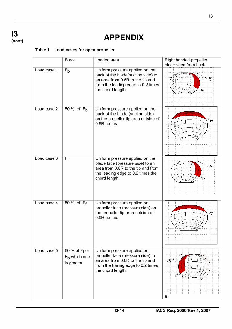
Table 1 Load cases for open propeller
Force Loaded area Right handed propellerblade seen from back
Load case 1 Fb Uniform pressure applied on theback of the blade(suction side) toan area from 0.6R to the tip andfrom the leading edge to 0.2 timesthe chord length.
Load case 2 50 % of Fb Uniform pressure applied on theback of the blade (suction side)on the propeller tip area outside of0.9R radius.
Load case 3 Ff Uniform pressure applied on theblade face (pressure side) to anarea from 0.6R to the tip and fromthe leading edge to 0.2 times thechord length.
Load case 4 50 % of Ff Uniform pressure applied onpropeller face (pressure side) onthe propeller tip area outside of0.9R radius.
Load case 5 60 % of Ff or
Fb which one
is greater
Uniform pressure applied onpropeller face (pressure side) toan area from 0.6R to the tip andfrom the trailing edge to 0.2 timesthe chord length.
e

I3
I3-15 IACS Req. 2006/Rev.1, 2007
I3(cont) Table 2 Load cases for ducted propeller
Force Loaded area Right handed propellerblade seen from back
Load case 1 Fb Uniform pressure applied on theback of the blade (suction side) toan area from 0.6R to the tip andfrom the leading edge to 0.2 timesthe chord length.
Load case 3 Ff Uniform pressure applied on theblade face (pressure side) to anarea from 0.6R to the tip and fromthe leading edge to 0.5 times thechord length.
Load case 5 60 % of Ff or
Fb which one
is greater
Uniform pressure applied onpropeller face (pressure side) toan area from 0.6R to the tip andfrom the trailing edge to 0.2 timesthe chord length.

I3
I3-16 IACS Req. 2006/Rev.1, 2007
I3(cont)
Figure 1 The shape of the propeller ice torque excitation for 45, 90, 135 degrees singleblade impact sequences and 45 degrees double blade impact sequence(twoice pieces) on a four bladed propeller.
0
0,2
0,4
0,6
0,8
1
1,2
0 90 180 270 360 450 540 630 720Angle of rotation [deg]
Q/Q
ma
x [
]
0
0,2
0,4
0,6
0,8
1
1,2
0 90 180 270 360 450 540 630 720Angle of rotation [deg]
Q/Q
ma
x [
]
0
0,2
0,4
0,6
0,8
1
1,2
0 90 180 270 360 450 540 630 720Angle of rotation [deg]
Q/Q
ma
x []
0
0,2
0,4
0,6
0,8
1
1,2
0 90 180 270 360 450 540 630 720Angle of rotation [deg]
Q/Q
max
[]
Ice block 2
Ice block 1
End ofDocument