requirements analysis. initialize use case for encounter encounter foreign character player designer...
TRANSCRIPT

REQUIREMENTSANALYSIS

Initialize Use Case for Encounter
Encounterforeign
character
player
designer Set rules
actors Encounter
Travel toadjacent
area
Initialize
1. System displays player’s main character in the dressing room.2. System displays a window for setting his character's qualities. 3. . . . .
InitializeUse case
Use case details
Adapted from Software Engineering: An Object-Oriented Perspective by Eric J. Braude (Wiley 2001), with permission.

Initialize Use Case for Encounter
Encounterforeign
character
player
designer Set rules
actors Encounter
Travel toadjacent
area
Initialize
1. System displays player’s main character in the dressing room.2. System displays a window for setting his character's qualities. 3. Player allocates the qualities of his main character. 4. Player chooses an exit from the dressing room.5. System moves player’s main character into the area on the other side of the exit.
InitializeUse case
Use case details
Adapted from Software Engineering: An Object-Oriented Perspective by Eric J. Braude (Wiley 2001), with permission.

Engage Foreign Character Use Case
player
designer
InitializeUse case
Encounter
Travel toadjacent
area
Set rules
Engage Foreign Character
1. System displays the foreign character in the same area as the player’s.
2. System exchanges quality values between the two characters.3. System displays the results of the engagement. 4. System displays player’s character in a random area.
Engageforeign
character
Use case details
Adapted from Software Engineering: An Object-Oriented Perspective by Eric J. Braude (Wiley 2001), with permission.

Conceptual Model of the System
Player
EncounterGame
Area
MainCharacter
ForeignCharacter1
1
n
111
1
n
Plays Has
Has
Has
Engagement
1
n
Has
Takes place in1
1
Entity RelationshipModel or Object Model

Data Flow Diagram: Explanation of Symbols
Account #& deposit
Get deposit
Check deposit
Processingelement
Data typeDirectionof data flow

Data Flow Diagram: Explanation of Symbols
Account #& deposit
balancequery
User
accountdatabase
accountdata
Get deposit
Create account
summary
Check deposit
Printer
Input
Output
Processingelement
Data typeDirectionof data flow
Data store
…...
Adapted from Software Engineering: An Object-Oriented Perspective by Eric J. Braude (Wiley 2001), with permission.
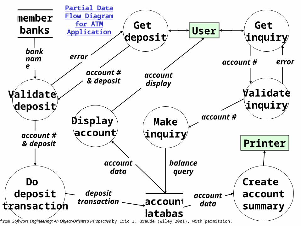
Partial Data Flow Diagram for ATM
Application
account #& deposit
balancequery
account #& deposit
account #
User
Makeinquiry
accountdatabase
deposittransaction
accountdata
Get deposit
Get inquiry
Validateinquiry
Do deposit
transaction
Create account
summary
Validate deposit
errorerror
Printer
memberbanks
bank name
Display account
account #
accountdata
accountdisplay
Adapted from Software Engineering: An Object-Oriented Perspective by Eric J. Braude (Wiley 2001), with permission.

Partial Encounter State-Transition Diagram
Setting up Preparing
Waiting
Complete setup
Foreign character
enters area
Engaging
Player clicks
qualities menu
Adapted from Software Engineering: An Object-Oriented Perspective by Eric J. Braude (Wiley 2001), with permission.
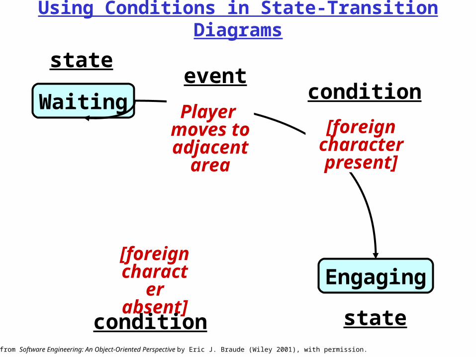
Using Conditions in State-Transition Diagrams
Engaging
Waiting
[foreign character absent]
[foreign character present]
Player moves to adjacent
area
eventcondition
condition
state
stateAdapted from Software Engineering: An Object-Oriented Perspective by Eric J. Braude (Wiley 2001), with permission.

Settingqualities
Sketch of Encounter State-Transition Diagram
Setting up
Engaging
Waiting
Player completes
setup
Player dismisses
report window
Reporting
Foreign character
enters area
Encounter completed
Player dismisses
set qualities widow
Player requests status
Player requests to
set qualities Foreign
character enters area
[foreign character absent]
[foreign character present]
Player moves to adjacent
areaPlayer quits
Adapted from Software Engineering: An Object-Oriented Perspective by Eric J. Braude (Wiley 2001), with permission.

Conceptualizing a System in terms of the User Interface
• Customers/Users often conceive a system in terms of its user interface
• Screen prototyping and story boarding (screen facade but no code) works well in connection with Use Case

Step 1: Know your user (C)‡
Step 2: Understand the business function in question (C)
Step 3: Apply principles of good screen design (C, D)
Step 4: Select the appropriate kind of windows (C, D)
Step 5: Develop system menus (C, D)
Step 6: Select the appropriate device-based controls (C)
Step 7: Choose the appropriate screen-based controls (C)
Step 8: Organize and lay out windows (C, D)
Step 9: Choose appropriate colors (D)
Step 10: Create meaningful icons (C, D)
Step 11: Provide effective message, feedback, & guidance (D)
Steps for Constructing User Interfaces*
* adapted from Galitz [Ga2] ‡ a C-requirement process

Applying Principles of Good Screen Design: “Before”
* see Galitz [Ga2]
Type checking saving mmf CD
Branch Main St. Elm St. High St.
Privileges newsletter discounts quick loans
First name
Middle name
Last name
Street
City
State/county
OK Apply Cancel Help
Adapted from Software Engineering: An Object-Oriented Perspective by Eric J. Braude (Wiley 2001), with permission.

Applying Principles of Good Screen Design: “After”
checking
OK Apply Cancel Help
Account type Privileges
saving
mmf
CD
newsletter
discounts
quick loans
Branch
Main St.
Elm St.
High St.
New Customers
Name
First
Middle
Last
Address
Street
City
State/county
Adapted from Software Engineering: An Object-Oriented Perspective by Eric J. Braude (Wiley 2001), with permission.

How Principles of Good Screen Design Were Applied
checking
OK Apply Cancel Help
Account type Privileges
saving
mmf
CD
newsletter
discounts
quick loans
Branch
Main St.
Elm St.
High St.
New Customers
Name
First
Middle
Last
Address
Street
City
State/county
Ensure consistency
Anticipate start
Align like elements
Grouplike elements
Border around like elements
Symmetry Balance
Proportion
Use Captions
Adapted from Software Engineering: An Object-Oriented Perspective by Eric J. Braude (Wiley 2001), with permission.

Window Usage1of 2
2. Purpose: obtain additional information so as to carry out a particular task or command
-- dialog window
Properties of automobile 189
Property Value
Brand Toyota
Model Camry
ID 893-8913-789014
Help
Word ___________________
This screen All screens
1. Purpose: display properties of an entity
-- property window
Adapted from Software Engineering: An Object-Oriented Perspective by Eric J. Braude (Wiley 2001), with permission.

3. Purpose: provide information -- message window
4. Purpose: present a set of controls -- palette window
5. Purpose: amplify information -- pop-up window
Window Usage 2of 2
ABC alert message
Caution: “age” must be < 120
OK
This is a popup window, designed to provide on-the-fly amplification
ABC controls
File Edit View Format Tools Help
monitor disk keyboard modem
Adapted from Software Engineering: An Object-Oriented Perspective by Eric J. Braude (Wiley 2001), with permission.
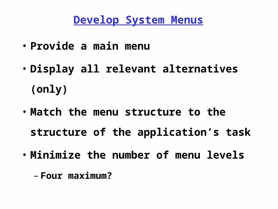
• Provide a main menu
• Display all relevant alternatives (only)
• Match the menu structure to the
structure of the application’s task
• Minimize the number of menu levels
– Four maximum?
Develop System Menus

Common GUI Terms
checking
Apply
Account type Privileges
saving
mmf
newsletter
discounts
New Customer
Name
First
Last
Cancel
Cascading windows
Tiledwindows
Text box
Radiobutton
Check boxButton
back
forward
Screen
Icon
Adapted from Software Engineering: An Object-Oriented Perspective by Eric J. Braude (Wiley 2001), with permission. Graphics reproduced with permission from Corel.

Preliminary Sketch of User Interface for Setting Game Character Qualities
16
Adapted from Software Engineering: An Object-Oriented Perspective by Eric J. Braude (Wiley 2001), with permission.

Preliminary Encounter Screen Shot
Name ofadjacent area
Name ofadjacent area
Name ofadjacent area
Name ofadjacent area
Adapted from Software Engineering: An Object-Oriented Perspective by Eric J. Braude (Wiley 20001), with permission. Graphics reproduced with permission from Corel.

Express Customer Requirements 1/2
• If the requirement is simple, and stands alone, express it in clear sentences within an appropriate section of the SRS
• If the requirement is an interaction between the user and the application, express via a use case. 1. Name the use case
2. Identify the “actor”
• the external user role-- usually a person
3. Write the sequence of user - application actions
• Minimize branching
• Use general form. Avoid specific names and values as in “Ed enters $300”. Instead, say “customer enters deposit amount”.
Adapted from Software Engineering: An Object-Oriented Perspective by Eric J. Braude (Wiley 2001), with permission.

• If the requirement involves process elements, each taking inputs, and producing outputs, use data flow. 1. Identify the processing elements (usually high level); show
as circles or rectangles2. Identify the data sources & destinations; show
as names between two horizontal lines3. Show the data paths among processing elements.
Indicate types of data flowing on each
• If the requirement involves states that the application can be in (or parts can be in)1. Identify the states (each a passive
verb, e.g., “waiting”); show as rounded rectangles2. Show initial state with special arrow 3. Identify the events (happenings external to the unit) that
cause transitions among the states; show as labeled arrows4. Identify sub-states; show as rectangles within rectangles
Express CustomerRequirements 2/2