required reading - custom works r/c · height adjuster into each oval on the rear pod plates as...
TRANSCRIPT
REQUIRED READINGThank You and Congratulations on purchasing this Aggressor! Within this kit you will find arace winning car with over 17 years worth of CUSTOM WORKS design and quality. In orderfor you to realize this race car’s winning potential it is important to follow the written textalong with the pictures included. The steps required to build this car are very easy, as longas you read before you build.
The instructional format for building this car is to open each bag in alphabeticalorder. Each bag of parts will be broken down into “Steps” in the manual. All partsand hardware needed to complete all steps for each separate bag, will be found ineach individual bag. There is no need to steal screws from other bags. In the rareevent you need to look in a different bag for a certain part, it will be noted clearly.
All hardware (screws, washers, nuts, etc…) are referred to by size and type in theinstructions. To help clarify which screw or nut the instruction is calling for refer to theHARDWARE REFERENCE supplement. The size of the screw or nut should match the“shadow” of the same piece very closely.
Screw ID’s are: FH=Flat Head BH=Button Head SH=Socket Head SS=Set Screw
Do NOT use power screwdrivers to drive screws into parts. The fast rotation speed can easilymelt and strip plastic parts or cross-thread into the aluminum parts.
REQUIRED TOOLS
Double Sided Tape .110" Drill Bit Super GlueHobby Scissors X-Acto Knife 220 Grit SandpaperSmall Needle Nose Pliers Phillips Head Screw Driver 400 Grit Sandpaper3/16" Wrench Blue Loctite #43 Drill Bit
Bag AChassis
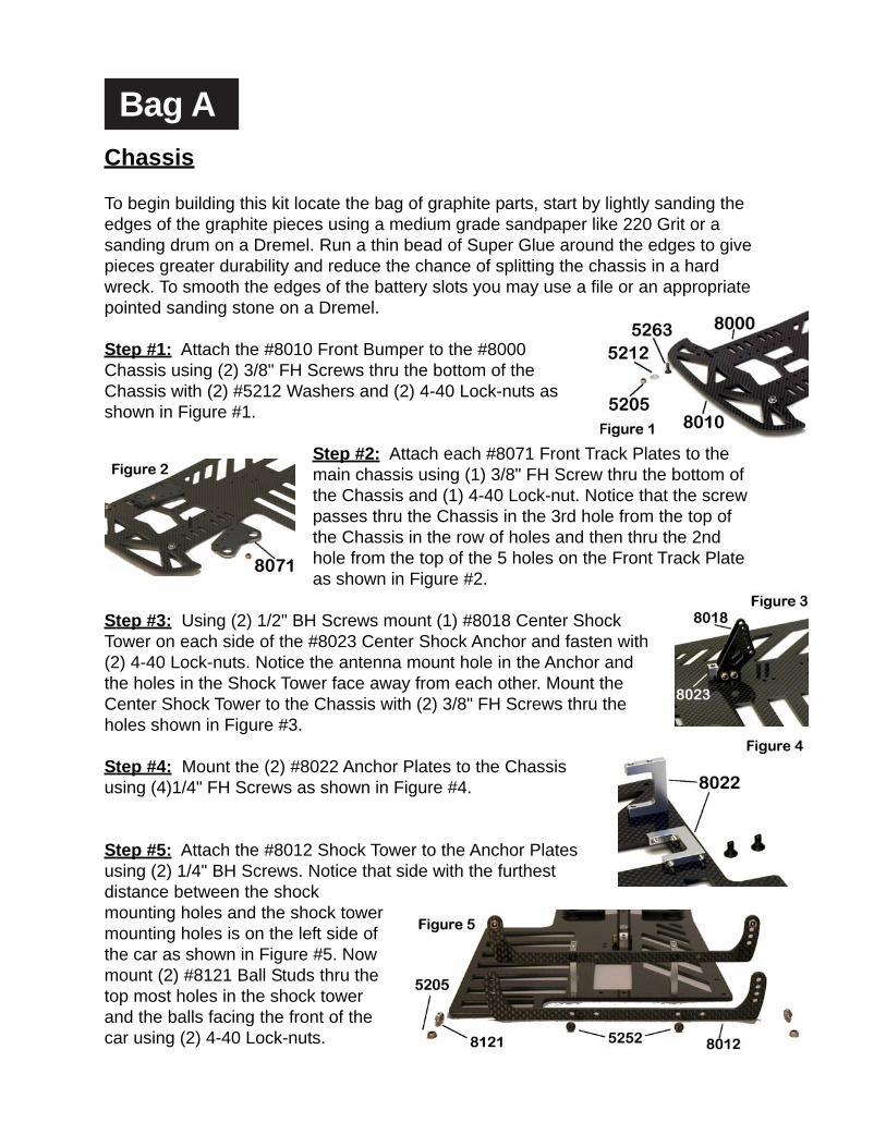
To begin building this kit locate the bag of graphite parts, start by lightly sanding theedges of the graphite pieces using a medium grade sandpaper like 220 Grit or asanding drum on a Dremel. Run a thin bead of Super Glue around the edges to givepieces greater durability and reduce the chance of splitting the chassis in a hardwreck. To smooth the edges of the battery slots you may use a file or an appropriatepointed sanding stone on a Dremel.
Step #1: Attach the #8010 Front Bumper to the #8000Chassis using (2) 3/8" FH Screws thru the bottom of theChassis with (2) #5212 Washers and (2) 4-40 Lock-nuts asshown in Figure #1.
Step #2: Attach each #8071 Front Track Plates to themain chassis using (1) 3/8" FH Screw thru the bottom ofthe Chassis and (1) 4-40 Lock-nut. Notice that the screwpasses thru the Chassis in the 3rd hole from the top ofthe Chassis in the row of holes and then thru the 2ndhole from the top of the 5 holes on the Front Track Plateas shown in Figure #2.
Step #3: Using (2) 1/2" BH Screws mount (1) #8018 Center ShockTower on each side of the #8023 Center Shock Anchor and fasten with(2) 4-40 Lock-nuts. Notice the antenna mount hole in the Anchor andthe holes in the Shock Tower face away from each other. Mount theCenter Shock Tower to the Chassis with (2) 3/8" FH Screws thru theholes shown in Figure #3.
Step #4: Mount the (2) #8022 Anchor Plates to the Chassisusing (4)1/4" FH Screws as shown in Figure #4.
Step #5: Attach the #8012 Shock Tower to the Anchor Platesusing (2) 1/4" BH Screws. Notice that side with the furthestdistance between the shockmounting holes and the shock towermounting holes is on the left side ofthe car as shown in Figure #5. Nowmount (2) #8121 Ball Studs thru thetop most holes in the shock towerand the balls facing the front of thecar using (2) 4-40 Lock-nuts.
Bag B
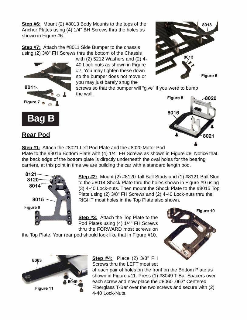
Step #6: Mount (2) #8013 Body Mounts to the tops of theAnchor Plates using (4) 1/4" BH Screws thru the holes asshown in Figure #6.
Step #7: Attach the #8011 Side Bumper to the chassisusing (2) 3/8" FH Screws thru the bottom of the Chassis
with (2) 5212 Washers and (2) 4-40 Lock-nuts as shown in Figure#7. You may tighten these downso the bumper does not move oryou may just barely snug thescrews so that the bumper will “give” if you were to bumpthe wall.
Rear Pod
Step #1: Attach the #8021 Left Pod Plate and the #8020 Motor PodPlate to the #8016 Bottom Plate with (4) 1/4" FH Screws as shown in Figure #8. Notice thatthe back edge of the bottom plate is directly underneath the oval holes for the bearingcarriers, at this point in time we are building the car with a standard length pod.
Step #2: Mount (2) #8120 Tall Ball Studs and (1) #8121 Ball Studto the #8014 Shock Plate thru the holes shown in Figure #9 using(3) 4-40 Lock-nuts. Then mount the Shock Plate to the #8015 TopPlate using (2) 3/8" FH Screws and (2) 4-40 Lock-nuts thru theRIGHT most holes in the Top Plate also shown.
Step #3: Attach the Top Plate to thePod Plates using (4) 1/4" FH Screwsthru the FORWARD most screws on
the Top Plate. Your rear pod should look like that in Figure #10.
Step #4: Place (2) 3/8" FHScrews thru the LEFT most setof each pair of holes on the front on the Bottom Plate asshown in Figure #11. Press (1) #8049 T-Bar Spacers overeach screw and now place the #8060 .063" CenteredFiberglass T-Bar over the two screws and secure with (2)4-40 Lock-Nuts.

Bag C
Rear Axle
Step #5: Finish mounting the T-Bar to the Rear Pod by mounting the#8017 Rear Steer Clip to the Bottom Plate with (2) 1/4" FH Screwsand (2) 4-40 Lock-nuts. The Clip should be mounted under the T-Barand on top of the Bottom Plate. Fasten the Clip to the T-Bar with (1)1/4" BH Screw and (1) 4-40 Lock-Nut as shown in Figure #12.
NOTE: The Rear Steer Clip has a notch on one end, this is the endused to angle the pod 1/2 Degree. The opposite end without thenotch is the 0 Degree side. To run the pod in the “offset” position, just flip the rearsteer clip over using the same end either with or without the notch.
Step #6: Following the assembly shown in Figure#13, mount the #8047 Pivot Ball Carriers and #8048Pivot Balls to the T-Bar using (4) 3/8" 2-56 X 3/8" BHScrews per Carrier. Just snug the Screws to thecarrier, the Pivot Balls should move very freely in theCarriers.
Step #7: Finally mount the T-Bar and Rear Podassembly to the Chassis using (2) 5/8" FHScrews thru the Chassis and secure with (2) 4-40Lock-Nuts. Your car should now look like the oneshown in Figure #14.
Step #1: Press (12) 1/8" Balls into the #4600 Spur Gear and (1) #1232 1/4" X 3/8"Unflanged Bearing to the center of the Gear. Place (1) #8035 D-Drive Diff Ring ontothe #8030 Axle so that the notch on the Axle and Ring line up. Apply a small amountof #4201 Blue Goo Grease to one side of the Diff Ring andon both sides of the Balls in the Spur Gear. Slide the gearonto the axle and apply a small amount of Grease to theother Diff Ring and slide it onto the axle as well with thegreased side facing the Spur Gear. Use Figure #15 as areference.
Bag DSide Shocks
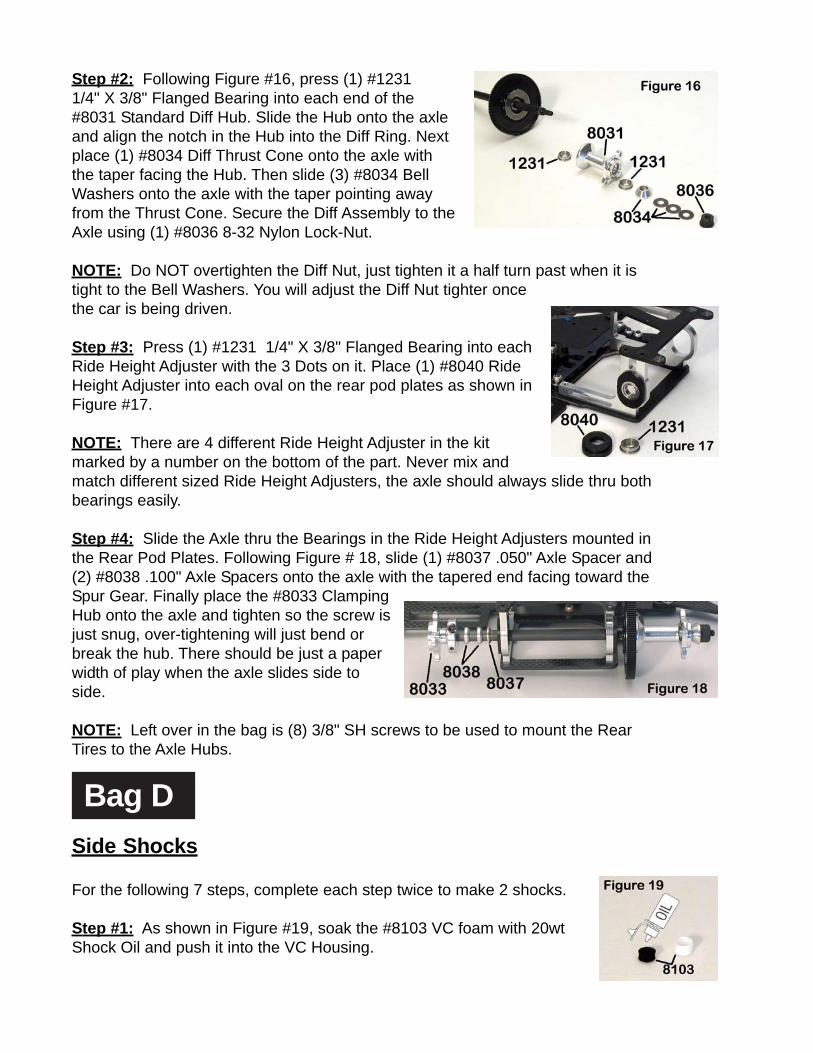
Step #2: Following Figure #16, press (1) #12311/4" X 3/8" Flanged Bearing into each end of the#8031 Standard Diff Hub. Slide the Hub onto the axleand align the notch in the Hub into the Diff Ring. Nextplace (1) #8034 Diff Thrust Cone onto the axle withthe taper facing the Hub. Then slide (3) #8034 BellWashers onto the axle with the taper pointing awayfrom the Thrust Cone. Secure the Diff Assembly to theAxle using (1) #8036 8-32 Nylon Lock-Nut.
NOTE: Do NOT overtighten the Diff Nut, just tighten it a half turn past when it istight to the Bell Washers. You will adjust the Diff Nut tighter oncethe car is being driven.
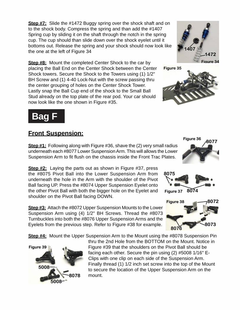
Step #3: Press (1) #1231 1/4" X 3/8" Flanged Bearing into eachRide Height Adjuster with the 3 Dots on it. Place (1) #8040 RideHeight Adjuster into each oval on the rear pod plates as shown inFigure #17.
NOTE: There are 4 different Ride Height Adjuster in the kitmarked by a number on the bottom of the part. Never mix andmatch different sized Ride Height Adjusters, the axle should always slide thru bothbearings easily.
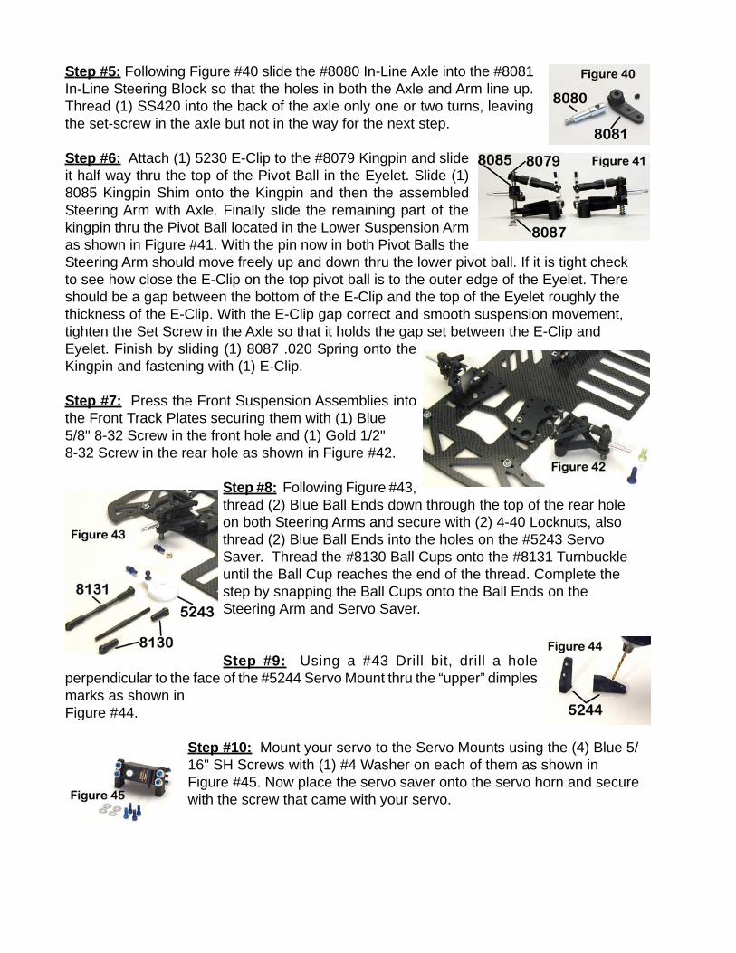
Step #4: Slide the Axle thru the Bearings in the Ride Height Adjusters mounted inthe Rear Pod Plates. Following Figure # 18, slide (1) #8037 .050" Axle Spacer and(2) #8038 .100" Axle Spacers onto the axle with the tapered end facing toward theSpur Gear. Finally place the #8033 ClampingHub onto the axle and tighten so the screw isjust snug, over-tightening will just bend orbreak the hub. There should be just a paperwidth of play when the axle slides side toside.
NOTE: Left over in the bag is (8) 3/8" SH screws to be used to mount the RearTires to the Axle Hubs.
For the following 7 steps, complete each step twice to make 2 shocks.
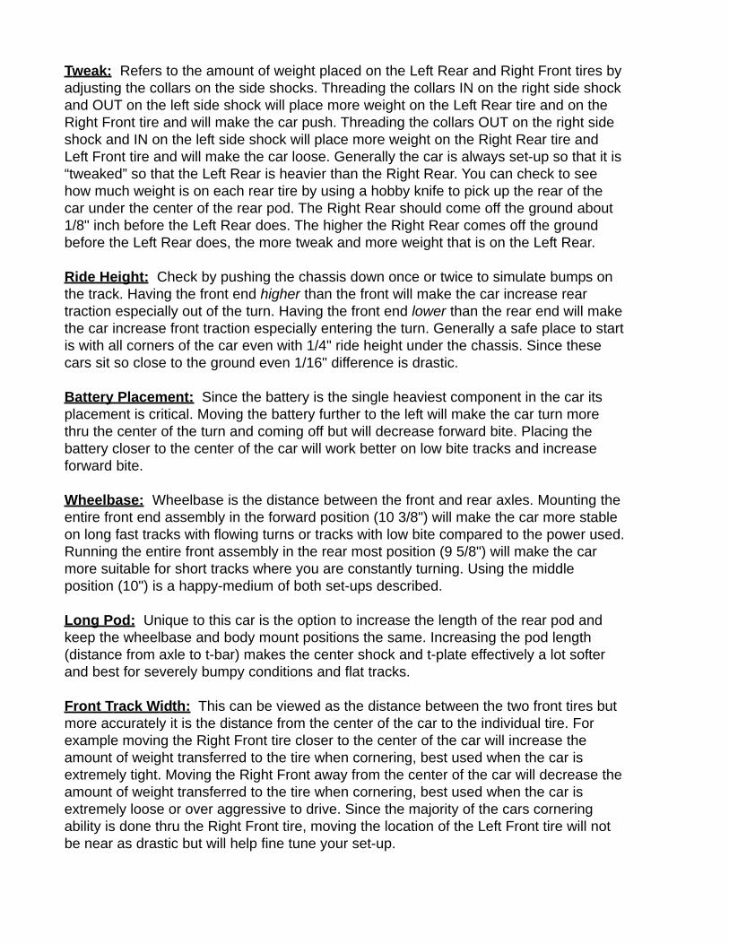
Step #1: As shown in Figure #19, soak the #8103 VC foam with 20wtShock Oil and push it into the VC Housing.

Center Shock
Bag E
Step#2: Fill the #8101 Shock Body with 30 weight shock oil up to the lineshown in Figure #20 and insert the #8102 Shock Piston all the way till itbottoms out.
Step #3: Following the sequence in Figure #21, place the VC Housing andFoam onto the Shock Shaft with the foam facing up. Next slide the smaller ofthe two washers onto the shaft, then the red O-ring followed by thelarger washer. Lastly slide on the 5 sided retaining clip.
Step #4: Holding the shock as shown in Figure #22,with the piston pressed to the bottom slide theAssembly Tool over the shaft and press the washers and o-ring into theshock body until the Retaining Clip is locked into place. The piston shouldrebound out of the shock when you press the clip into place. Test the shockby pressing the shaft back into the shock, the Retaining Clip should not
pop-out, if so the shock has too much oil. The shaft should rebound back out smoothlyafter you release your finger.
Step #5: Thread (1) #5235 Long Ball Cup onto both the Shock Bodyand the #8104 Shock Shaft End until the Ball Cup reaches the end ofthe threads. Your shock should look like the one shown in Figure #23.
Step #6: Slide the Shock Shaft into the Shaft End so that the shaftbottoms out. Make sure there are no burrs remaining in the Shaft Endand thread the Set Screw into the Shaft End as shown in Figure #24.
Step #7: Slide the #8105 silver springs overthe Shock Body and onto the Shaft End. As
shown in Figure #25 hold the spring down and thread on the SpringCollar to retain the spring on the shock.
Step #8: Now mount the side shocks to the car by snappingthe ball cups onto the ball studs on top of the rear pod plate andthe balls at the top of the side shock towers. Refer to Figure#26.
Step #1: Mount (1) #1403 Large Black O-ring into the groove onthe #1402 Threaded Shock Collar as shown in Figure #27. Add adrop of Shock Oil to the O-ring and thread it onto the #1401Threaded Shock Body with the “shoulder” facing down.

Step #2: Soak the #1411 VC Foam with the Shock Oil and install it ontothe VC Bobbin as shown in Figure #28.
Step #3: Remove the #1405 Shock Pistons with the “2” on them fromthe parts tree as shown in Figure #29. Be SURE to REMOVE ANYBURRS on the Shock Piston, or your shock will NOT work correctly.Add a #5230 E-Clip to each side of the #2 Shock Piston on the #1415Shock Shaft. Install (1) #1406 O-ring over the threads on the TOP ofthe Shock Body. Both of these are shown in Figure #30.
Step #4: Following the sequence of parts in Figure #31,slide the VC Bobbin from Step #2 on the Shock Shaft andthen (2) #1250 O-Rings. Add a couple drops of oil to the O-Rings and insert the entire Shock Assembly into the ShockBody and FIRMLY pull the Shock Shaft through in order to“seat” the VC Bobbin. Thread #8130 Ball Cup onto Shock Shaftuntil threads are all the way inside the ball cup.
Step #5: Press the Pivot Ball into the #5228 Ball End. Thread theBall End onto the #1418 Aluminum Shock Cap so that the distancefrom the center of the Pivot Ball to the top of the cap is no less than 5/8".
Step #6: To fill the Shocks with oil and complete their assembly followthe picures and text provided in Figure #33.
Bag F
Step #7: Slide the #1472 Buggy spring over the shock shaft and onto the shock body. Compress the spring and than add the #1407Spring cup by sliding it on the shaft through the notch in the springcup. The cup should than slide down over the shock eyelet until itbottoms out. Release the spring and your shock should now look likethe one at the left of Figure 34
Step #8: Mount the completed Center Shock to the car byplacing the Ball End on the Center Shock between the CenterShock towers. Secure the Shock to the Towers using (1) 1/2"BH Screw and (1) 4-40 Lock-Nut with the screw passing thruthe center grouping of holes on the Center Shock Tower.Lastly snap the Ball Cup end of the shock to the Small BallStud already on the top plate of the rear pod. Your car shouldnow look like the one shown in Figure #35.
Front Suspension:
Step #1: Following along with Figure #36, shave the (2) very small radiusunderneath each #8077 Lower Suspension Arm. This will allows the LowerSuspension Arm to fit flush on the chassis inside the Front Trac Plates.
Step #2: Laying the parts out as shown in Figure #37, pressthe #8075 Pivot Ball into the Lower Suspension Arm fromunderneath the hole in the Arm with the shoulder of the PivotBall facing UP. Press the #8074 Upper Suspension Eyelet ontothe other Pivot Ball with both the bigger hole on the Eyelet andshoulder on the Pivot Ball facing DOWN.
Step #3: Attach the #8072 Upper Suspension Mounts to the LowerSuspension Arm using (4) 1/2" BH Screws. Thread the #8073Turnbuckles into both the #8076 Upper Suspension Arms and theEyelets from the previous step. Refer to Figure #38 for example.
Step #4: Mount the Upper Suspension Arm to the Mount using the #8078 Suspension Pinthru the 2nd Hole from the BOTTOM on the Mount. Notice inFigure #39 that the shoulders on the Pivot Ball should befacing each other. Secure the pin using (2) #5008 1/16" E-Clips with one clip on each side of the Suspension Arm.Finally thread (1) 1/2 inch set screw into the top of the Mountto secure the location of the Upper Suspension Arm on themount.
Step #5: Following Figure #40 slide the #8080 In-Line Axle into the #8081In-Line Steering Block so that the holes in both the Axle and Arm line up.Thread (1) SS420 into the back of the axle only one or two turns, leavingthe set-screw in the axle but not in the way for the next step.
Step #6: Attach (1) 5230 E-Clip to the #8079 Kingpin and slideit half way thru the top of the Pivot Ball in the Eyelet. Slide (1)8085 Kingpin Shim onto the Kingpin and then the assembledSteering Arm with Axle. Finally slide the remaining part of thekingpin thru the Pivot Ball located in the Lower Suspension Armas shown in Figure #41. With the pin now in both Pivot Balls theSteering Arm should move freely up and down thru the lower pivot ball. If it is tight checkto see how close the E-Clip on the top pivot ball is to the outer edge of the Eyelet. Thereshould be a gap between the bottom of the E-Clip and the top of the Eyelet roughly thethickness of the E-Clip. With the E-Clip gap correct and smooth suspension movement,tighten the Set Screw in the Axle so that it holds the gap set between the E-Clip andEyelet. Finish by sliding (1) 8087 .020 Spring onto theKingpin and fastening with (1) E-Clip.
Step #7: Press the Front Suspension Assemblies intothe Front Track Plates securing them with (1) Blue5/8" 8-32 Screw in the front hole and (1) Gold 1/2"8-32 Screw in the rear hole as shown in Figure #42.
Step #8: Following Figure #43,thread (2) Blue Ball Ends down through the top of the rear holeon both Steering Arms and secure with (2) 4-40 Locknuts, alsothread (2) Blue Ball Ends into the holes on the #5243 ServoSaver. Thread the #8130 Ball Cups onto the #8131 Turnbuckleuntil the Ball Cup reaches the end of the thread. Complete thestep by snapping the Ball Cups onto the Ball Ends on theSteering Arm and Servo Saver.
Step #9: Using a #43 Drill bit, drill a holeperpendicular to the face of the #5244 Servo Mount thru the “upper” dimplesmarks as shown inFigure #44.
Step #10: Mount your servo to the Servo Mounts using the (4) Blue 5/16" SH Screws with (1) #4 Washer on each of them as shown inFigure #45. Now place the servo saver onto the servo horn and securewith the screw that came with your servo.

Bag G
Step #11: Measure the hole spacing on the bottomof servo mounts so that you can mark their positionson the Chassis. You want the steering linkagesangled and the servo mount centered in the car asshown in Figure #46. Using the 10" Wheelbase, anapproximate distance from the center of the servomount holes to the front edge of the Chassis is 4.00"as view by the grey line on the Chassis in Figure #46.Once you have marked the positions of the 2 holesneeded drill the chassis using a .110" Drill Bit. If youhave a countersink bit it is recommended tocountersink from the bottom of the chassis. You can now mount the servo usingeither (2) 3/8" FH screws or use the (2) 3/8" BH Screws if you did not countersinkthe holes.
NOTE: Left over in the bag is (2) Lock-Nuts and (4) #1233 Flanged Bearings to beused to mount the front tires to the Axles.
Body Mounts and Misc:
Step #1: Mount the (2) #8110 2" Body Posts to the Front Bumper shown in Figure #47using (2) 3/8" BH Screws. Slide the Body Post Collar over the Post and thread (1) SetScrew into the collar to hold the body height position.
Step #2: Mount the (2) #8111 3" Body Posts to the Rear Body Mountsshown in Figure #48 using (2) 3/8" BH Screws. Slide the Body PostCollar over the Post and thread (1) Set Screw into the collar to hold thebody height position.
Step #3: Mount the (1) #8112 4" Body Post in the center ofthe Chassis shown in Figure #49 using (1) 3/8" FH Screws.Slide the Body Post Collar over the Post and thread (1) SetScrew into the collar to hold the body height position.
Step #4: Slide your antenna thru thehole in the Center Shock Anchor and also thru the #3209 AntennaTube. Press the Tube into the Center Shock Anchor and place theAntenna Cap over the end of the Tube and Antenna Wire. Usingdouble-sided tape mount your receiver to the Chassis in thesuggested position shown in Figure #50. Speed Control placementcan vary and usually ends up wherever you are not currently runningyour battery pack.

Now mount your choice of tires and wheels and body on the car and you are ready to go.
Congratulations!!
You have now completed the assembly process of your new Custom WorksAggressor kit. In the next section of this manual you will find some basic setup hints andadvice. It is important to remember that all tracks and racing surfaces are different.Therefore the suggestions we give you are general in nature and should by no meansbe treated as the only options.
TUNING TIPS: These are some general guidelines for optimizing handlingperformance. None of these “tips” are EVER set in stone. On any given day this manualor any chassis engineering book or guru can be proved wrong by the almighty stopwatch. A good way to approach chassis set-up is to try one change, practice it, think howthe car felt different from before, and compare lap times from the stop watch…..this willnever fail.
Car is Loose or Oversteers
Install Wing to Rear of CarSlide Wing Toward Rear of Car
Increase Wing AngleAdd Wedge/Tweak to Chassis Using Side
ShocksSofter Side Shock Springs
Stiffer Front SpringsSofter Center Shock Spring
Decrease Center Shock Spring TensionTry Harder Front Compound TireTry Softer Rear Compound TireMove Battery to Center of Car
Raise Front Ride HeightLower Rear Ride Height
Move RF Suspension OutMove RR Tire Closer to Pod
Increase Castor
Car Pushes or Understeers
Slide Wing Toward Front of CarDecrease Wing Angle
Remove Wedge/Tweak to Chassis UsingSide Shocks
Stiffer Side Shock SpringsSofter Front Springs
Stiffer Center Shock SpringDecrease Center Shock Spring Tension
Try Softer Front Compound TireTry Harder Rear Compound TireMove Battery Toward Left Side
Lower Front Ride HeightRaise Rear Ride HeightMove RF Suspension IN
Move RR Tire Away From PodDecrease Castor
Car is Erratic:
Bent Front Suspension Pin: Remove spring and check for free movementChunked Tire: Check side wall to see if rubber is still glued to wheel.
Bent Axle: Tire “wobbles” while spinning.Loose Screws: Especially Chassis Screws, add Blue Loctite to prevent.
Bound Ball Joint: Steering link and shocks should spin free on balls.Shocks: Either Bound Up, Bent Shaft, or Out of Oil.
Bearings: Broken or completely seized.Foreign Objects: Unlucky Dirt/Stones preventing suspension movement especially in front pivot
balls.Bottoming Out: Look on bottom side of chassis for buffed or scratched areas.
Tire Rub: Look on inside of body for extreme black marks from tires.Blown Differential
Radio Problem: Bad Servo, Weak Servo Saver Spring, Transmitter Pot blown.

Castor: Angle of the kingpin in relation to a vertical plane as viewed from the side of thecar. Increasing the angle will make the car more stable out of the turn as well as down thestraights and increase steering entering a turn. Decreasing the angle will make the car feelmore “touchy” at high speeds and help steering while exiting the turn.
Front Toe IN: Front edge of car tires point toward the chassis as viewed from above thecar. Settles and makes steering reaction less aggressive especially on acceleration. Easierset-up to drive and works well on bumpy tracks.
Front Toe OUT: Front edge of car tires point away from the chassis as viewed from abovethe car. Increases aggressiveness of car especially on entry to the turn. Works well onsmooth, high bite tracks where rear traction is not a problem. Generally the preferred set-upfor pan car racing.
Camber: Angle by which the tire and wheel contacts the racing surface when viewed fromthe Front or Rear of the car. Oval cars generally always have the Right Side tires leaningTOWARD the chassis and the Left Side tires leaning AWAY from the chassis. In oval racingjargon, more camber means more angle TOWARD the chassis on the Right Side and moreangle AWAY from the chassis on the Left Side. Starting from 0 Degrees (tire standingstraight up) ADDING camber in the oval fashion will increase traction when corneringhowever remember too much of anything is generally a bad thing. Camber is usuallyadjusted (especially foam tires) when one edge of the tire is wearing more than the other.
Camber Gain: Angle of the Upper Suspension Arm relative to the ground, so that when thesuspension travels the amount of camber for that tire will increase. With the arm parallel tothe ground the front suspension will have the least amount of camber gain. Lowering theUpper Suspension Arm on the Upper Suspension Mount will increase the amount ofcamber gained when the suspension travels. There is not a “correct” set-up and once againtoo much of anything is generally bad. This will help change the “feel” of the car thru theturns.
Shock Angle (Center Shock): Mounting the shock in the lower positions will increase thestiffness of the spring and generally works best on smooth high bite tracks. Mounting thecenter shock in the upper positions (shock parallel to the ground) will make the spring feelsofter and works best on low grip surfaces and bumpy tracks as well.
Shock Angle (Side Shocks): Mounted in the shocks in the lower positions will increasethe stiffness of the spring and will decrease chassis roll which is good for high bite tracksand especially flat tracks. Side Shocks mounted in the upper holes (shocks parallel to theground) will make the springs feel softer and will increase chassis roll which seems to bebest for cap tire racing and low bite flat tracks.
Tweak: Refers to the amount of weight placed on the Left Rear and Right Front tires byadjusting the collars on the side shocks. Threading the collars IN on the right side shockand OUT on the left side shock will place more weight on the Left Rear tire and on theRight Front tire and will make the car push. Threading the collars OUT on the right sideshock and IN on the left side shock will place more weight on the Right Rear tire andLeft Front tire and will make the car loose. Generally the car is always set-up so that it is“tweaked” so that the Left Rear is heavier than the Right Rear. You can check to seehow much weight is on each rear tire by using a hobby knife to pick up the rear of thecar under the center of the rear pod. The Right Rear should come off the ground about1/8" inch before the Left Rear does. The higher the Right Rear comes off the groundbefore the Left Rear does, the more tweak and more weight that is on the Left Rear.
Ride Height: Check by pushing the chassis down once or twice to simulate bumps onthe track. Having the front end higher than the front will make the car increase reartraction especially out of the turn. Having the front end lower than the rear end will makethe car increase front traction especially entering the turn. Generally a safe place to startis with all corners of the car even with 1/4" ride height under the chassis. Since thesecars sit so close to the ground even 1/16" difference is drastic.
Battery Placement: Since the battery is the single heaviest component in the car itsplacement is critical. Moving the battery further to the left will make the car turn morethru the center of the turn and coming off but will decrease forward bite. Placing thebattery closer to the center of the car will work better on low bite tracks and increaseforward bite.
Wheelbase: Wheelbase is the distance between the front and rear axles. Mounting theentire front end assembly in the forward position (10 3/8") will make the car more stableon long fast tracks with flowing turns or tracks with low bite compared to the power used.Running the entire front assembly in the rear most position (9 5/8") will make the carmore suitable for short tracks where you are constantly turning. Using the middleposition (10") is a happy-medium of both set-ups described.
Long Pod: Unique to this car is the option to increase the length of the rear pod andkeep the wheelbase and body mount positions the same. Increasing the pod length(distance from axle to t-bar) makes the center shock and t-plate effectively a lot softerand best for severely bumpy conditions and flat tracks.
Front Track Width: This can be viewed as the distance between the two front tires butmore accurately it is the distance from the center of the car to the individual tire. Forexample moving the Right Front tire closer to the center of the car will increase theamount of weight transferred to the tire when cornering, best used when the car isextremely tight. Moving the Right Front away from the center of the car will decrease theamount of weight transferred to the tire when cornering, best used when the car isextremely loose or over aggressive to drive. Since the majority of the cars corneringability is done thru the Right Front tire, moving the location of the Left Front tire will notbe near as drastic but will help fine tune your set-up.
Rear Track Width: Distance from the rear pod the tires are mounted. This isaccomplished using spacers on the axle located between the bearing and the hubs.Moving the Right Rear away from the pod will increase steering in the center of the turnand exiting while decreasing forward bite off the turn. Moving the Right Rear closer tothe pod will increase forward bite thru the center of the turn and especially while exiting.The opposite can be said for the location of the left rear. Mounting the left rear close to thepod will increase steering thru the center of the turn and decrease forward bite off the turn,while mounting it further from the pod will increase stability and forward bite whilecornering.
Rear Pod (On-Center or Offset): Mounting the pod “on-center” positions the motor(which is the majority of the weight of the rear pod) pretty much center in the rear pod andgenerally works best in wide open type driving classes like stock. Mounting the pod “off-set” places the motor closer to the left rear tire and helps keep the left rear tire plantedduring acceleration and works well in modified classes.
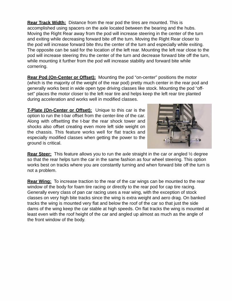
T-Plate (On-Center or Offset): Unique to this car is theoption to run the t-bar offset from the center-line of the car.Along with offsetting the t-bar the rear shock tower andshocks also offset creating even more left side weight onthe chassis. This feature works well for flat tracks andespecially modified classes when getting the power to theground is critical.
Rear Steer: This feature allows you to run the axle straight in the car or angled ½ degreeso that the rear helps turn the car in the same fashion as four wheel steering. This optionworks best on tracks where you are constantly turning and when forward bite off the turn isnot a problem.
Rear Wing: To increase traction to the rear of the car wings can be mounted to the rearwindow of the body for foam tire racing or directly to the rear pod for cap tire racing.Generally every class of pan car racing uses a rear wing, with the exception of stockclasses on very high bite tracks since the wing is extra weight and aero drag. On bankedtracks the wing is mounted very flat and below the roof of the car so that just the sidedams of the wing keep the car stable at high speeds. On flat tracks the wing is mounted atleast even with the roof height of the car and angled up almost as much as the angle ofthe front window of the body.
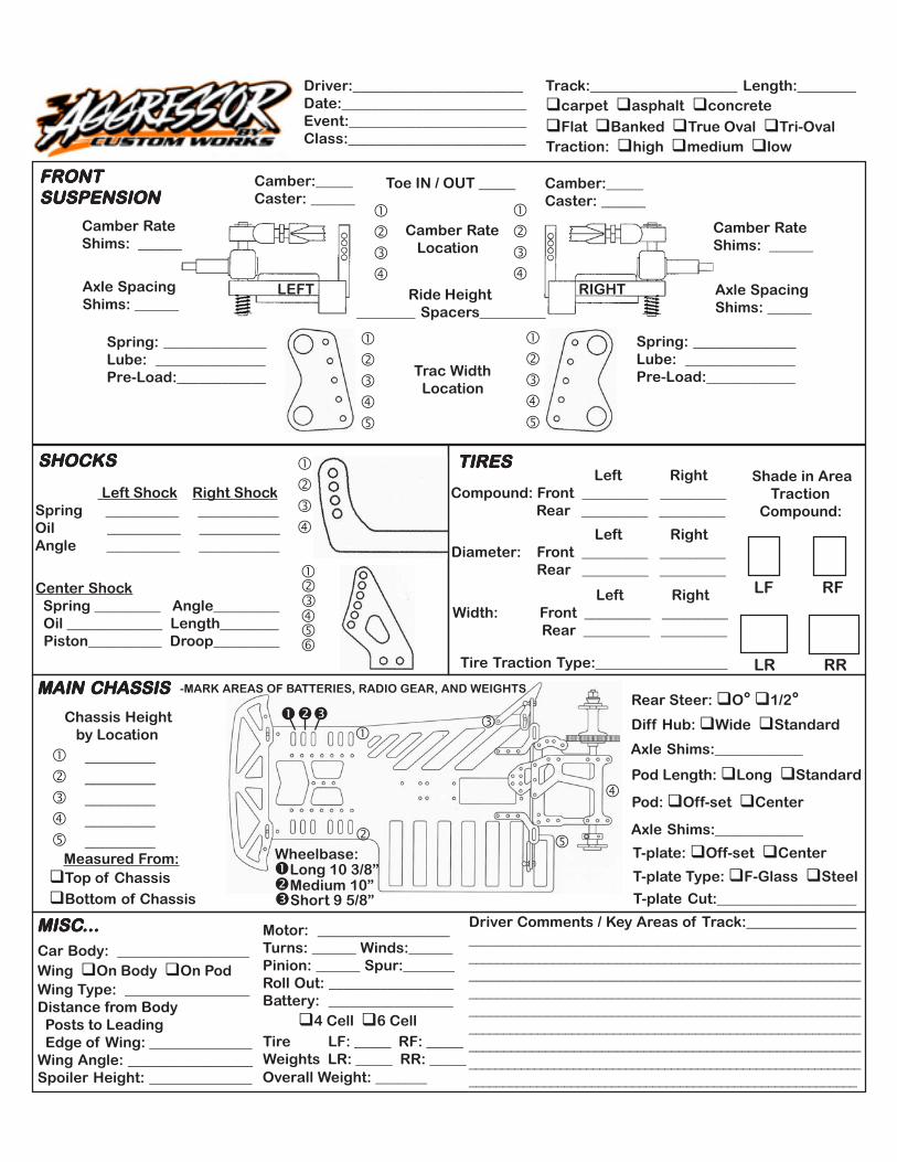
Driver:_______________________Date:_________________________Event:________________________Class:________________________
Track:____________________ Length:________carpet asphalt concreteFlat Banked True Oval Tri-Oval
Traction: high medium low
Ride Height________ Spacers_________
Camber:_____Caster: ______
Camber:_____Caster: ______
RIGHTLEFT
Camber RateShims: ______
Axle SpacingShims: ______
Axle SpacingShims: ______
Camber RateShims: ______
Camber Rate Location
Toe IN / OUT _____
Spring: ______________Lube: _______________Pre-Load:____________
Spring: ______________Lube: _______________Pre-Load:____________ Trac Width
Location
FRONTFRONTFRONTFRONTFRONTSUSPENSIONSUSPENSIONSUSPENSIONSUSPENSIONSUSPENSION
SHOCKSSHOCKSSHOCKSSHOCKSSHOCKS
Left Shock Right Shock Spring __________ ___________ Oil __________ ___________ Angle __________ ___________
Center Shock Spring _________ Angle_________ Oil _____________ Length________ Piston__________ Droop_________
TIRESTIRESTIRESTIRESTIRES Left RightCompound: Front _________ _________ Rear _________ _________
Left RightDiameter: Front _________ _________ Rear _________ _________
Left RightWidth: Front _________ _________ Rear _________ _________
Shade in Area Traction Compound:
Tire Traction Type:__________________
LF RF
LR RR
MAIN CHASSISMAIN CHASSISMAIN CHASSISMAIN CHASSISMAIN CHASSIS -MARK AREAS OF BATTERIES, RADIO GEAR, AND WEIGHTS
T-plate: Off-set Center
Pod: Off-set Center
Diff Hub: Wide Standard
Axle Shims:____________
Axle Shims:____________
________ ________ ________ ________ ________
Chassis Height by Location
Top of ChassisBottom of Chassis
Measured From:
Tire LF: _____ RF: _____Weights LR: _____ RR: _____Overall Weight: _______
MISCMISCMISCMISCMISC...............Car Body: __________________Wing On Body On PodWing Type: _________________Distance from Body Posts to Leading Edge of Wing: ______________Wing Angle: _________________Spoiler Height: ______________
Motor: __________________Turns: ______ Winds:______Pinion: ______ Spur:_______Roll Out: _________________Battery: _________________ 4 Cell 6 Cell
Driver Comments / Key Areas of Track:_______________________________________________________________________________________________________________________________________________________________________________________________________________________________________________________________________________________________________________________________________________________________________________________________________________________________________________________________________________________________________________________________________
Pod Length: Long Standard
Rear Steer: O° 1/2°
T-plate Type: F-Glass Steel
T-plate Cut:___________________
Wheelbase:Long 10 3/8”Medium 10”Short 9 5/8”

Custom Works RC Products, LLC. 760-B Crosspoint Drive Denver, NC 28037 (704)489-8147 phone (704)489-0488 fax www.CustomWorksRC.com
Jan. 2005 PRICE LISTPart# Description Price Part# Description Price0800 Aggressor Speedway Kit 460.00$ 8036 8/32 Nylon Locknut (4) 2.00$
1231 1/4" X 3/8" Flanged Bearing 18.00$ 8037 .050 Axle Spacer (2) 3.00$
1232 1/4" X 3/8" Unflanged Bearing 9.00$ 8038 .100 Axle Spacer (2) 3.00$
1233 3/16"x5/16" Flanged Bearings (2) 16.00$ 8040 Axle Ride Height #1,2,3&4 5.00$
1250 Silicone O-Rings (8) 2.50$ 8046 2-56 BHS for Pivot Socket (8) 1.50$
1401 Threaded Shock Body (pr) 14.00$ 8047 Pivot Ball Carrier (2) 3.00$
1402 Threaded Shock Collar 4.00$ 8048 Pivot Ball (2) 4.00$ 1403 Threaded Collar O-ring (4) 4.00$ 8049 T-Bar Spacers (molded) 1.00$ 1405 Shock Piston Set 3.00$ 8060 Centered T-Plate .063" Fiberglass 8.00$ 1406 Shock Cap O-ring 2.00$ 8061 Offset T-Plate .063" Fiberglass 8.00$ 1407 Shock Spring Cups (4) 5.00$ 8071 Front Trac Plates (pair) 26.00$ 1411 GX Shock Rebuild Kit (4) 4.00$ 8072 Upper Suspension Mount 0deg. 15.00$ 1415 Shock Shaft .71 3.00$ 8073 Upper Susp. Arm Turnbuckle (2) 2.50$ 1418 Center Shock Cap 9.00$ 8074 Upper Suspension Arm Eyelet (2) 2.00$ 1460 Aggressor Center Shock 15.00$ 8075 Front Suspension Pivot Ball (2) 3.00$ 1472 Silver Center Shock Spring 3.85lb 2.00$ 8076 Upper Suspension Arm (2) 3.00$ 3209 Antenna Tube 2.00$ 8077 Lower Suspension Arm (pair) 4.00$ 4201 Blue Goo Diff Grease 3.00$ 8078 Hinge Pin and E-Clips 7.00$ 4600 100T 64 pitch Spur Gear 4.00$ 8079 King Pin (2) 4.00$ 5228 Small Ball End 5.50$ 8080 Axle for On-Center Block 3.00$ 5243 Servo Saver 7.00$ 8081 On-Center Steering Block (pair) 2.50$ 5244 Servo Mount 2.00$ 8082 Axle for Offset Block (pair) 2.50$ 8000 Chassis 100.00$ 8083 Offset Steering Block (pair) 2.00$ 8010 Front Bumper 20.00$ 8084 Front Ride Height Spacer (4) 2.00$ 8011 Nerf Wing 7.00$ 8085 King Pin Shim (10) 2.00$ 8012 Shock Tower 15.00$ 8087 .020 Front Suspension Spring 2.50$ 8013 Body Mount 7.00$ 8100 VCS Side Shock Kit 15.00$ 8014 Shock Plate 7.00$ 8101 Side Shock Body 2.50$ 8015 Top Plate 15.00$ 8102 Side Shock Shaft and Piston 3.00$ 8016 Bottom Plate 15.00$ 8103 Side Shock Rebuild Kit 4.00$ 8017 Rear Steer Clip 5.00$ 8104 Side Shock Shaft End 3.50$ 8018 Center Shock Tower (2) 13.00$ 8105 Silver VCS Spring (2) 2.00$ 8020 Motor Pod Plate 22.00$ 8106 Green VCS Spring (2) 2.00$ 8021 Left Pod Plate 17.00$ 8110 2" Front Body Post 3.00$ 8022 Anchor Plate 11.00$ 8111 3" Rear Body Post 3.00$ 8023 Center Shock Anchor 9.00$ 8112 4" Center Body Post 3.00$ 8030 Axle 27.00$ 8115 Self-Sticking Front Bumper 7.00$ 8031 Standard Diff Hub 24.00$ 8120 Tall Ball Stud (2) 3.00$ 8032 Off-Set Diff Hub 24.00$ 8121 Small Ball Stud (4) 4.00$ 8033 Left Side Clamping Hub 22.00$ 8130 Small Ball Cup (14) 5.00$ 8034 Thrust Cone and Bell Washers(3) 2.00$ 8131 Turnbuckle 2" Steel 4.00$ 8035 D-Drive Rings (pair) 2.00$

Part# Hardware Price Part# T-Shirts and Sweatshirts Price5008 1/16" E-Clips 2.00$ 1500M Custom Works T-Shirt (M) 18.00$ 5205 Aluminum Locknut 4-40 (10) 5.00$ 1500L Custom Works T-Shirt (L) 18.00$ 5208 Motor Screw 3x6mm 3.00$ 1500XL Custom Works T-Shirt (XL) 18.00$ 5212 #4 Flat Washer (20) 2.00$ 1500XXL Custom Works T-Shirt (XXL) 20.00$ 5228 Camber Link Ball End short (4) 5.50$ 1500XXXL Custom Works T-Shirt (XXXL) 20.00$ 5230 1/8" E-Clip 2.00$ 1600M Custom Works Sweat Shirt (M) 25.00$ 5235 Long Ball Cup (4) 2.00$ 1600L Custom Works Sweat Shirt (L) 25.00$ 5250 4-40x3/16" Button Head Screw (4) 2.00$ 1600XL Custom Works Sweat Shirt (XL) 25.00$ 5252 4-40x1/4" Button Head Screw (8) 2.00$ 1600XXL Custom Works Sweat Shirt (XXL) 28.00$ 5253 4-40x3/8" Button Head Screw (8) 2.00$ 1600XXXL Custom Works Sweat Shirt (XXXL) 28.00$ 5254 4-40x1/2" Button Head Screw (8) 2.00$ 5255 4-40x5/8" Button Head Screw (8) 2.00$ 5262 4-40x1/4" Flat Head Screw (8) 2.00$ 5263 4-40x3/8" Flat Head Screw (8) 2.00$ 5264 4-40x1/2" Flat Head Screw (8) 2.00$ 5265 4-40x5/8" Flat Head Screw (8) 2.00$ 5274 4-40x1/2" Socket Head Screw (4) 2.00$ 5275 4-40x5/8" Socket Head Screw (4) 2.00$ 5277 4-40x7/8" Socket Head Screw (4) 2.00$ 5278 4-40x1" Socket Head Screw (4) 2.00$ 5279 4-40x3/4 Socket w/hole (wing) 7.00$
Part# Optional Shock Springs Price1470 Brown Center Shock Spring 2.8 lb 2.00$ 1471 Green Center Shock Spring 3.5 lb. 2.00$ 1473 Blue Center Shock Spring 4.2 lb 2.00$ 8086 .018 Front Suspension Spring 2.50$ 8088 .022 Front Suspension Spring 2.50$ 8089 .024 Front Suspension Spring 2.50$
Part# Optional Parts & Miscellaneous Price1405 Shock Piston Set #1, 2, 3 3.00$ 8050 Centered T-Plate SOFT Steel 20.00$ 8051 Offset T-Plate SOFT Steel 20.00$ 8052 Centered T-Plate MEDIUM Steel 20.00$ 8053 Offset T-Plate MEDIUM Steel 20.00$ 8054 Centered T-Plate FIRM Steel 20.00$ 8055 Offset T-Plate FIRM Steel 20.00$