reproductions supplied by edrs are the best that can … · individual components of which are then...
TRANSCRIPT
ED 444 346
TITLE
INSTITUTION
ISBNPUB DATENOTEAVAILABLE FROM
PUB TYPEEDRS PRICEDESCRIPTORS
ABSTRACT
DOCUMENT RESUME
EF 005 763
Maintenance of Electrical Services: Maintenance and Renewalin Educational Buildings. Building Bulletin 76.Department for Education and Employment, London (England).Architects and Building Branch.ISBN-0-11-270799-81992-00-0078p.HMSO Publications Centre, P.O. Box 276, London, SW8 5DTEngland. Tel: 071-873-9090; Fax: 071-873-8200.Guides - Non-Classroom (055)MF01/PC04 Plus Postage.*Electrical Systems; Elementary Secondary Education;*Guidelines; Public Schools; *School Maintenance
This document provides guidance on the overall electricalservices and maintenance strategy in educational facilities, the individualcomponents of which are considered in the following sections: recorddocumentation and systems; inspection and testing; condition appraisal;maintenance requirements; and maintenance works procedures. Other sectionsinclude discussions on electrical requirements for particular uses, communityuse, spare capacity, and tasks for school staff. Many specific types of
electrical services are considered and their planned maintenance requirementsare dealt with in the appendices. (Contains 30 references, 19 figures, and 15
tables.) (GR)
Reproductions supplied by EDRS are the best that can be madefrom the original document.
Maintenance and Renewal in Educational Buildings
Maintenance of Electrical ServicesU.S. DEPARTMENT OF EDUCATION
Office of Educational Research and ImprovementEDU ATIONAL RESOURCES INFORMATION
CENTER (ERIC)This document has been reproduced asreceived from the person or organizationoriginating it.
Minor changes have been made toimprove reproduction quality.
Points of view or opinions stated in thisdocument do not necessarily representofficial OERI position or policy. 1
PERMISSION TO REPRODUCE ANDDISSEMINATE THIS MATERIAL HAS
BEEN GRANTED BY
John Birch
TO THE EDUCATIONAL RESOURCESINFORMATION CENTER (ERIC)
BAST COPY AVAILABLE ,,k_ )
Building Bulletin 76Architects and Building Branch
2
DES111 IENI111011
EWAN EKE
Building Bulletin 76
Maintenance and Renewalin Educational Buildings
Maintenance of Electrical Services
London: HMSO
Department of Education and Science
Sanctuary BuildingsGreat Smith StreetLondon SW1P 3BT
Elizabeth HouseYork RoadLondon SE1 7PH
Tel. 071-925 5000
Crown copyright 1992Applications for reproduction should bemade to HMSO.First published 1992
ISBN 0 11 270799 8
Edited by DES Information BranchDesigned by Sheila BirdIB/1016/11/5
I I
riContents
2
3
4
5
6
7
8
9
10
11
12
13
B
C
D
E
F
G
HI
J
K
Acknowledgements
Summary vi
Introduction 1
Current practice and expenditure 3
Strategy 4
Record documentation and systems 6
Inspection and testing 11
Condition appraisal 14
Maintenance requirements 16
Maintenance works procedures 17
Educational requirements 19
Energy 22
Community use 24
Flexibility and spare capacity 25
Maintenance tasks for staff 27
AppendicesGuidance to governing bodies
Planned maintenance of fixed electrical installations
Planned maintenance of lighting installations
Planned maintenance of stage lighting
Planned maintenance of emergency lightingPlanned maintenance of building services controls
Planned maintenance of fire alarm systems
Planned maintenance of intruder alarm systemsPlanned maintenance of electrical equipment
Planned electrical maintenance of swimming-pools
Planned maintenance of lightning protection systems
Planned maintenance of lifts
30
32
39
45
46
47
49
51
53
56
57
58
Glossary 61
Addresses of professional associations 62
References 63
1
2
3
4
5
6
7
8
9
10
11
12
13
14
15
16
17
18
19
1
2
3
4
5
6
7
8
9
10
11
12
13
14
15
FiguresMechanical and electrical maintenance expenditure in nine educationalinstitutions, 1988/89 3
Maintenance records 7
An example of asset coding 8
Maintenance record system 10
Inspection and test equipment 11
Specimen inspection and test record with hypothetical condition assessment 13
Typical computer workstations 20Possible additional requirements for community use 24
Possible areas to incorporate spare capacity 26Hand-held infrared scanner 33
Distribution boards 36Light loss factors: components and their effects 40Life-cycle costing for a lighting installation 42
BS 5839: Part 1: 1988: Model logbook page for fire alarm systems 50
The symbol for double insulation of equipment 53
Portable appliance test sheet 54
BS 1363 plug and socket outlet 55
Typical points of a lightning protection system which require attention during plannedmaintenance 59
Typical lift inspection form 60
TablesMinimum requirements for an equipment record 7
Inspections and tests 12
Notional equipment life 14
Example of condition grading 15
Cost of utilities 22
Basic staff maintenance tasks 27
Possible staff maintenance tasks (after suitable training) 28Obtaining the services of qualified engineers and electricians 31
Switchgear components 32
Types of RCD and sensitivities 33
Cable systems 34Socket outlets in a new secondary school 38Light loss factors for the example in Figure 12 39Fluorescent lamp life (effect of switching) 44Incandescent lamp life (effect of voltage variation) 44
El
Acknowledgements
This Bulletin is based on research carriedout by the Building Services Research andInformation Association (BSRIA). TheDepartment of Education and Science(DES) would like to thank the BSRIA teamled by Mr M. Smith for all their efforts inconnection with this work.
Thanks are also due to local educationauthorities (LEAs) that provided details oftheir maintenance operations andexperiences. The Department would alsolike to thank the Society of Chief Electricaland Mechanical Engineers in localgovernment (SCEME) for their invaluablehelp during the production of this Bulletin.
DES Project Team MembersHead of Division B. WhitehousePrincipal Engineer M. J. PatelSenior Engineer K. Gofton
El
Summary
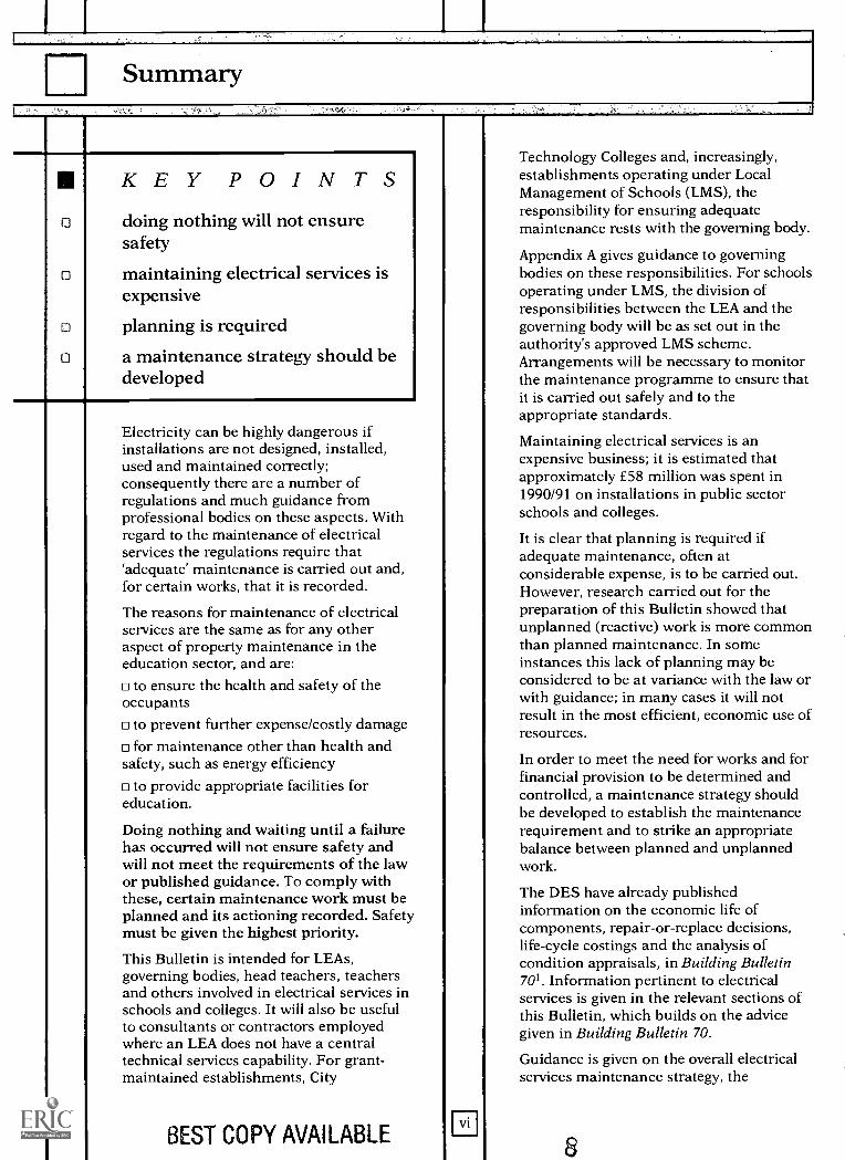
KEY POINTSdoing nothing will not ensuresafety
maintaining electrical services isexpensive
planning is required
a maintenance strategy should bedeveloped
Electricity can be highly dangerous ifinstallations are not designed, installed,used and maintained correctly;consequently there are a number ofregulations and much guidance fromprofessional bodies on these aspects. Withregard to the maintenance of electricalservices the regulations require that`adequate' maintenance is carried out and,for certain works, that it is recorded.
The reasons for maintenance of electricalservices are the same as for any otheraspect of property maintenance in theeducation sector, and are:
to ensure the health and safety of theoccupants
to prevent further expense/costly damagefor maintenance other than health and
safety, such as energy efficiencyto provide appropriate facilities for
education.
Doing nothing and waiting until a failurehas occurred will not ensure safety andwill not meet the requirements of the lawor published guidance. To comply withthese, certain maintenance work must beplanned and its actioning recorded. Safetymust be given the highest priority.
This Bulletin is intended for LEAs,governing bodies, head teachers, teachersand others involved in electrical services inschools and colleges. It will also be usefulto consultants or contractors employedwhere an LEA does not have a centraltechnical services capability. For grant-maintained establishments, City
BEST COPY AVAILABLE II
Technology Colleges and, increasingly,establishments operating under LocalManagement of Schools (LMS), theresponsibility for ensuring adequatemaintenance rests with the governing body.
Appendix A gives guidance to governingbodies on these responsibilities. For schoolsoperating under LMS, the division ofresponsibilities between the LEA and thegoverning body will be as set out in theauthority's approved LMS scheme.Arrangements will be necessary to monitorthe maintenance programme to ensure thatit is carried out safely and to theappropriate standards.
Maintaining electrical services is anexpensive business; it is estimated thatapproximately £58 million was spent in1990/91 on installations in public sectorschools and colleges.
It is clear that planning is required ifadequate maintenance, often atconsiderable expense, is to be carried out.However, research carried out for thepreparation of this Bulletin showed thatunplanned (reactive) work is more commonthan planned maintenance. In someinstances this lack of planning may beconsidered to be at variance with the law orwith guidance; in many cases it will notresult in the most efficient, economic use ofresources.
In order to meet the need for works and forfinancial provision to be determined andcontrolled, a maintenance strategy shouldbe developed to establish the maintenancerequirement and to strike an appropriatebalance between planned and unplannedwork.
The DES have already publishedinformation on the economic life ofcomponents, repair-or-replace decisions,life-cycle costings and the analysis ofcondition appraisals, in Building Bulletin701. Information pertinent to electricalservices is given in the relevant sections ofthis Bulletin, which builds on the advicegiven in Building Bulletin 70.
Guidance is given on the overall electricalservices maintenance strategy, the
individual components of which are thenconsidered in sections such as:
Record documentation and systems
Inspection and testing
Condition appraisal
Maintenance requirements
Maintenance works procedures.
Other sections deal briefly with topics suchas electrical requirements for particularuses, energy, community use, sparecapacity and tasks for school staff.
Many specific types of electrical servicehave been considered and their plannedmaintenance requirements are dealt with inthe appendices.
Introduction
KEY POINTSrecent electrical maintenance ineducation has cost £58 million p.a.
common standards across anestate are desirable
reasons for maintenance: safety,damage limitation, energyefficiency, appropriate facilities
responsibilities for maintenanceshould be understood
Maintenance is expensive. The most recentfigures from the Society of Chief Architectsof Local Authorities (SCALA) onmaintenance expenditure for 19902 showthat £7.82 per m2 per annum is the averagecost of all maintenance in public sectoreducational premises and approximately30% of that figure is the combined cost ofmechanical and electrical maintenance.Figures are not available in sufficient detailto differentiate between mechanical andelectrical work but it is believed thatapproximately £58 million per annum isspent on electrical maintenance ineducational establishments3.
A strategy for the maintenance of electricalsystems must have safety as the firstpriority in order to comply with the law. Anumber of regulations relate to the safe useof electricity in buildings and a wealth ofguidance is produced by professionalbodies, such as the Institution of ElectricalEngineers (IEE), and GovernmentDepartments, such as the Health and SafetyExecutive (HSE) and the Health and SafetyCommission (HSC). In April 1990 a numberof outdated statutes were replaced by theElectricity at Work Regulations 19894.These regulations make a number ofabsolute requirements with regard to whatwork must be done, how it is to beperformed and by whom, although theyinclude very few exact technicalrequirements.
The same standards should be appliedacross the whole of each site and estate, forboth existing and new facilities. If anexisting facility is considered unsafe,adequate steps must be taken to rectify thesituation immediately. This may meancurtailing the use of a facility until it isbrought up to standard.
The major routine maintenancerequirements of electrical installations areinspection and testing of the equipment etcto ensure that it is safe to operate. Thenature of the materials used and the well-documented design and installationprocedures produce systems that inherentlyhave a long life, their limiting factors beingcapacity and lack of flexibility. To take fulladvantage of this longevity it is essentialthat maintenance is planned and recorded.
In cases of vandalism maintenance willobviously be necessary. Every opportunityshould be taken to reduce risk of damagethrough planned maintenance, by theselection of appropriate materials andinstallation methods.
The need to replace equipment often resultsfrom the obsolescence of existingequipment, caused not only through agebut also change in manufacturers' rangeswhen it might not be possible to obtainreplacements, and because of revisions toregulations or standards.
There is an increasing use of the electricalsystems for teaching purposes. Designers oforiginal installations could not haveenvisaged the current growth in the use ofelectricity in educational establishments;consequently a high proportion of futuremaintenance work will be involved in themodification of electrical installations toprovide for current and future teachingneeds.
The introduction of LMS, with the LEAassuming a formalised role of landlord,requires adequate arrangements to ensurethat acceptable standards are maintained,particularly in the maintenance of recordsof systems, with responsibilities clearlydefined and agreed. The exact allocation ofresponsibilities will be as set out in theauthority's approved LMS scheme. Theschool's responsibilities will probably
0
accord with the division as set out in AnnexA of DES Circular 7/885 as a minimum.
The governing body may consider askingparents (for example through ParentTeacher Associations - PTAs) or others tovolunteer to carry out expansion orimprovement of the electrical installations.This is acceptable in principle, providedthat the choice of persons who do the work,the method of doing the work and the finalresults comply with the law. This will meanonly qualified persons may design andcarry out the work, i.e. electrical engineersto design and electricians to carry out thework, using suitable materials throughout.They must carry sufficient insurance coverfor third party liability whilst carrying outthe work and provide 'as-fitted' drawings,records and test certificates on completionof the work. They must also recognise theirresponsibility for professional liability forthe life of the installation. A governing bodycould be held liable for an incident arisingfrom a substandard installation which hadbeen designed or installed by unqualifiedpersonnel. Subsequent maintenance of thework must also be ensured, throughnegotiation with those responsible. DIYelectrical work in schools has in the pastproduced significant safety hazardsbecause some of the work was carried outby persons without knowledge of, andattention to, the codes of practice and thelaw, and no records were kept of the workdone.
Governing bodies and head teachers willfind the summary and Sections 1-3, 8, 13and Appendix A of this Bulletin ofparticular interest, and other sections andappendices when dealing with specificaspects. Engineers, architects and thosedesigning and specifying works in schoolswill find the technical appendices usefultogether with the practical guidance givenin the main text.
11
2 Current practice and expenditure
KEY POINTSmost maintenance is reactive andunplanned and therefore notcost-effective
breakdown cannot be preventedcompletely
A full analysis was not possible in thepreparation of this Bulletin, but the smallsample of buildings considered revealedthat reactive maintenance is far moreprevalent than planned and preventivemaintenance; accurate planning, budgetingand control are therefore not attainable inthese cases and the targets suggested inDesign Note 406 are not being achieved.
The reliance on maintenance which islargely a response to breakdowns impliesthat in some cases only manipulation ofbudgets, and the implementation ofunplanned work near the end of thefinancial year, ensures that actualexpenditure and planned budgets correlate.This does not mean that either the budgetor the workload should be totally inflexible;however, reacting to circumstances as theyarise does seem a poor way of reconcilingthe forecast with the outcome. It is alsorecognised that breakdowns cannot beentirely prevented, hence the need forflexibility.
From research carried out in thepreparation of this Bulletin, it is apparentthat many responsible for maintenance areunable to differentiate between plannedand unplanned work in their previousmaintenance expenditure, or betweenmechanical and electrical work; nor couldthe cost of labour and materials, on-costsor profits be derived for future estimatingpurposes.
There is still a high reliance on the intrinsicknowledge of a small number of specialistsurveyors (building and engineering). Thisknowledge is extremely valuable butwithout systematic records it is easily lost,as over time these specialists move on.
BEST COPY AVAILABLE
The use of computers in maintenanceplanning appears to be minimal.Consequently accurate maintenanceworkload and budget planning andinformation on workloads and cost controlfor individual properties is expensive toobtain from manual records or is lost.
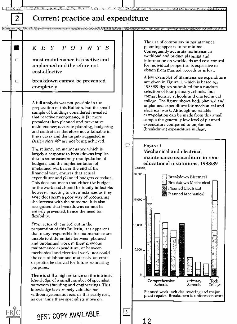
A few examples of maintenance expenditureare given in Figure 1, which is based on1988/89 figures submitted for a randomselection of four primary schools, fourcomprehensive schools and one technicalcollege. The figure shows both planned andunplanned expenditure for mechanical andelectrical work. Although no reliableextrapolation can be made from this smallsample the generally low level of plannedexpenditure compared to unplanned(breakdown) expenditure is clear.
Figure 1Mechanical and electricalmaintenance expenditure in nineeducational institutions, 1988/89
Cost (es)
20,000
15,000
10,000
5,000 _
0
Breakdown ElectricalBreakdown MechanicalPlanned Electrical
21 Planned Mechanical
gEComprehensive
SchoolsPrimarySchools
Tech.College
Planned work includes rewiring and majorplant repairs. Breakdown is unforeseen work
12
piStrategy
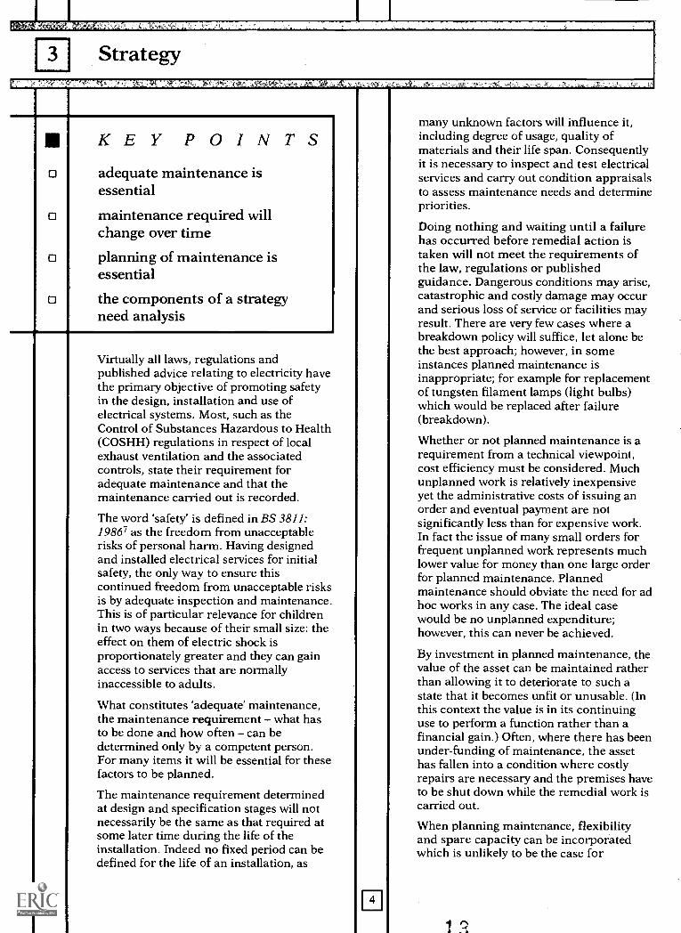
KEY POINTSadequate maintenance isessential
maintenance required willchange over time
planning of maintenance isessential
the components of a strategyneed analysis
Virtually all laws, regulations andpublished advice relating to electricity havethe primary objective of promoting safetyin the design, installation and use ofelectrical systems. Most, such as theControl of Substances Hazardous to Health(COSHH) regulations in respect of localexhaust ventilation and the associatedcontrols, state their requirement foradequate maintenance and that themaintenance carried out is recorded.
The word 'safety' is defined in BS 3811:19867 as the freedom from unacceptablerisks of personal harm. Having designedand installed electrical services for initialsafety, the only way to ensure thiscontinued freedom from unacceptable risksis by adequate inspection and maintenance.This is of particular relevance for childrenin two ways because of their small size: theeffect on them of electric shock isproportionately greater and they can gainaccess to services that are normallyinaccessible to adults.
What constitutes 'adequate' maintenance,the maintenance requirement - what hasto be done and how often - can bedetermined only by a competent person.For many items it will be essential for thesefactors to be planned.
The maintenance requirement determinedat design and specification stages will notnecessarily be the same as that required atsome later time during the life of theinstallation. Indeed no fixed period can bedefined for the life of an installation, as
4
many unknown factors will influence it,including degree of usage, quality ofmaterials and their life span. Consequentlyit is necessary to inspect and test electricalservices and carry out condition appraisalsto assess maintenance needs and determinepriorities.
Doing nothing and waiting until a failurehas occurred before remedial action istaken will not meet the requirements ofthe law, regulations or publishedguidance. Dangerous conditions may arise,catastrophic and costly damage may occurand serious loss of service or facilities mayresult. There are very few cases where abreakdown policy will suffice, let alone bethe best approach; however, in someinstances planned maintenance isinappropriate; for example for replacementof tungsten filament lamps (light bulbs)which would be replaced after failure(breakdown).
Whether or not planned maintenance is arequirement from a technical viewpoint,cost efficiency must be considered. Muchunplanned work is relatively inexpensiveyet the administrative costs of issuing anorder and eventual payment are notsignificantly less than for expensive work.In fact the issue of many small orders forfrequent unplanned work represents muchlower value for money than one large orderfor planned maintenance. Plannedmaintenance should obviate the need for adhoc works in any case. The ideal casewould be no unplanned expenditure;however, this can never be achieved.
By investment in planned maintenance, thevalue of the asset can be maintained ratherthan allowing it to deteriorate to such astate that it becomes unfit or unusable. (Inthis context the value is in its continuinguse to perform a function rather than afinancial gain.) Often, where there has beenunder-funding of maintenance, the assethas fallen into a condition where costlyrepairs are necessary and the premises haveto be shut down while the remedial work iscarried out.
When planning maintenance, flexibilityand spare capacity can be incorporatedwhich is unlikely to be the case for
1 2.
unplanned, reactive maintenance. Thus itmay be possible to accommodate to someextent educational requirements,requirements for community use, energyconservation works, etc in the course ofroutine maintenance.
Works need to be carried out in such amanner as to ensure the safety of both theoperative carrying out the task andeveryone else who may be associated withthe works and their effects. Hence safe,efficient and cost-effective worksprocedures are essential.
Many authorities choose to deal withenergy consumption, energy savingmeasures, maintenance, refurbishment andthe provision of new buildings by havingseparate management structures and costcentres dealing with each. It is difficult toco-ordinate and plan expenditure if eachdepartment has different objectives andworking methods. In order to ensureadequate and cost-effective action from allviewpoints, it is essential to have a coherentmaintenance strategy, clearly understoodand accommodating the objectives of allwhere possible.
Hence a strategy for maintenance ofelectrical services must be establishedwhich addresses the matters consideredabove and includes:
Record Documentation and SystemsInspection and TestingCondition AppraisalMaintenance RequirementsWorks ProceduresEducational RequirementsEnergyCommunity UseFlexibility and Spare Capacity.
Each of these aspects is considered ingreater detail in the following sections.
1L
Record documentation and systems
0
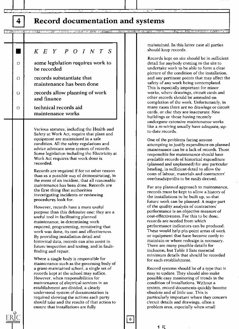
KEY POINTSsome legislation requires work tobe recorded
records substantiate thatmaintenance has been done
records allow planning of workand finance
technical records aidmaintenance works
Various statutes, including the Health andSafety at Work Act, require that plant andequipment are maintained in a safecondition. All the safety regulations andadvice advocate some system of records.Some legislation including the Electricity atWork Act requires that work done isrecorded.
Records are required if for no other reasonthan as a possible way of demonstrating, inthe event of an incident, that all reasonablemaintenance has been done. Records arethe first thing that authoritiesinvestigating incidents or reviewingprocedures look for.
However, records have a more usefulpurpose than this defensive one: they are auseful tool in facilitating plannedmaintenance, in determining workrequired, programming, monitoring thatwork was done, its cost and effectiveness.By providing installation detail andhistorical data, records can also assist infuture inspection and testing, and in fault-finding and repair.
Where a single body is responsible formaintenance such as the governing body ofa grant-maintained school, a single set ofrecords kept at the school may suffice.However, when responsibilities formaintenance of electrical services in anestablishment are divided, a clearlyunderstood system of documentation isrequired showing the actions each partyshould take and the results of that action toensure that installations are fully
6
maintained. In this latter case all partiesshould keep records.
Records kept on site should be in sufficientdetail for anybody coming to the site toundertake work to be able to form a clearpicture of the condition of the installation,and any pertinent points that may affect thesafety of any work being contemplated.This is especially important for minorworks, where drawings, circuit cards andother records should be amended oncompletion of the work. Unfortunately, inmany cases there are no drawings or circuitcards, or else they are inaccurate. Newbuildings or those having recentlyundergone extensive maintenance workslike a re-wiring usually have adequate, up-to-date records.
One of the problems facing anyoneattempting to justify expenditure on plannedmaintenance can be a lack of records. Thoseresponsible for maintenance should haveavailable records of historical expenditure(planned and unplanned) for any particularheading, in sufficient detail to allow thecosts of labour, materials and contractors'overheads/profits to be easily derived.
For any planned approach to maintenance,records must be kept to allow a history ofthe installations to be built up, so thatfuture work can be planned. A major partof the quality analysis of contractors'performance is an objective measure ofcost-effectiveness. For this to be done,records are needed from whichperformance indicators can be produced.These would help pin-point areas of workor equipment that have become costly tomaintain or where redesign is necessary.There are many possible details forinclusion, but Table 1 lists essentialminimum details that should be recordedfor each establishment.
Record systems should be of a type that iseasy to update. They should also makepossible easy monitoring of trends in thecondition of installations. Without asystem, record documents quickly becomeobsolete and of little use. This isparticularly important where they concerncircuit details and drawings, often aproblem area, especially when small
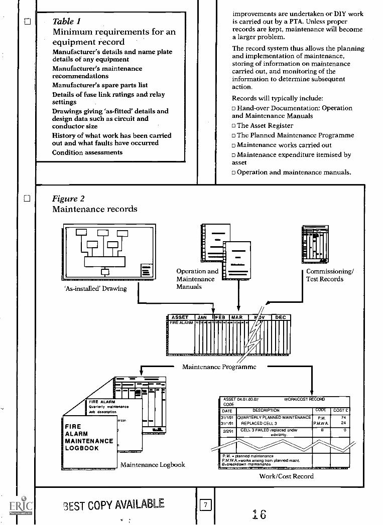
Table 1Minimum requirements for anequipment recordManufacturer's details and name platedetails of any equipmentManufacturer's maintenancerecommendationsManufacturer's spare parts listDetails of fuse link ratings and relaysettingsDrawings giving 'as-fitted' details anddesign data such as circuit andconductor sizeHistory of what work has been carriedout and what faults have occurredCondition assessments
improvements are undertaken or DIY workis carried out by a PTA. Unless properrecords are kept, maintenance will becomea larger problem.
The record system thus allows the planningand implementation of maintenance,storing of information on maintenancecarried out, and monitoring of theinformation to determine subsequentaction.
Records will typically include:Hand-over Documentation: Operation
and Maintenance Manualso The Asset Register
The Planned Maintenance Programmeo Maintenance works carried out
Maintenance expenditure itemised byasset
Operation and maintenance manuals.
Figure 2Maintenance records
'As-installed' Drawing
11Operation andMaintenanceManuals
//ASEE Er2: 1 MEI MAR W. J III DECR
11111111111111iIIIIIIII
FIRE ALARM 1775Quarterly maintenanceJob description
erson
FIREALARMMAINTENANCELOGBOOK
Maintenance Programme
Maintenance Logbook
Commissioning/Test Records
ASSET 04.01.03.02 WORK/COST RECORD
CODE
DATE DESCRIPTION CODE COST £
31/1/91
31/1/91
QUARTERLY PLANNED MAINTENANCE
REPLACED CELL 3P.M.
P.M.W.A.
7424
2/2191 CELL 3 FAILED replaced underwarranty.
B 0
P.M. = planned maintenanceP.M.W.A. =works arising from planned mainl.
, 13.1makdown maintenance
Work/Cost Record
3EST COPY AVAILABLE
rr'
The record system should be built aroundthe Operation and Maintenance Manual(s)which are more fully described in BuildingBulletin 70'. For existing installationswhere such manuals do not exist it isrecommended that a programme to preparethem be instigated.
These manuals contain full details of whateach service comprises including 'as-installed' drawings, the results of initialinspection, testing and commissioning ofthe service, device ratings and settings, theplanned maintenance necessary to sustainthe service safely, and the frequency ofsuch maintenance.
Experience shows that many contractorsare reluctant to provide these manuals, orthat when they do the documents are ofdubious quality. Many organisations arenow employing third party specialistorganisations to prepare these documents.
Asset Register
From the operation and maintenancemanual, or from a survey of existinginstallations, an Asset Register is preparedwhich records all the assets, or componentparts, of the various electrical servicestogether with the particular details of each,such as make, model, serial number,specialist maintenance contractor, etc.
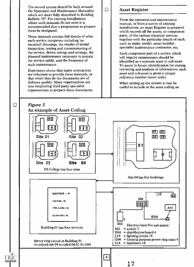
Each component part of a service whichwill require maintenance should beidentified as a separate asset or sub-asset.To assist in future identification for storing,retrieving and analysis of information, eachasset and sub-asset is given a uniquereference number (asset code).
When setting up the system it may beuseful to include in the asset coding an
Figure 3An example of Asset Coding
I=1CM CI
ME
Site 01
Site 03
CO
ME
1=1
ME
Site 02
ME
Site 04FE College has four sites
ELECTRICS = 01
HEATING = 02
FIRE ALARM = 03
E/LIGHTING = 04
Building 01 has four services
Hence ring circuit in Building 01on school site 04 is coded 04.01.01.G04
01
m
0
Site 04 has five buildings
S03 Electrics have five sub-assets:S03 = switch 3D04 = distribution board 4L19 = lighting circuit 19G04 = General purpose power ring main 4Al4 = Appliance 14
8
element to identify the person responsiblefor maintenance costs. For examplemaintenance of the fixed electricalinstallation may be the responsibility of theLEA, whereas a particular appliance mayfall to another department or theestablishment itself.
For a small establishment, in a singlebuilding where each individual electricalservice is of the same age, type, etc theasset coding philosophy may need toinclude only references to the service anditem.
For larger properties with many buildings,each with installations of differing types,ages, etc it will be necessary to furtherdivide the main assets (the services) intosub-assets for each building.
For registers covering many sites, such asthose of further education colleges, it willbe necessary to include identification of thesite as well. The extent of subdivision willdepend on the complexity of services on thesite.
Asset coding principles should be as simpleas possible whilst containing all necessaryinformation; unwieldy codes are difficult touse. Figure 3 gives an example of coding.
Planned maintenanceprogramme
On the basis of the information containedin the operation and maintenance manual aprogramme can be prepared, detailingwhen individual maintenance tasks foreach asset need to be carried out togetherwith job descriptions of the work involvedin each task.
Where responsibilities for maintenance aredivided it is recommended that an overallprogramme be prepared and agreedbetween the parties, clearly showing thedivision of responsibilities.
Maintenance works
This record will contain details of allplanned action including the task, the dateit was carried out, who carried it out anddetails of any other action shown to benecessary. For some tasks a test resultssheet will also be needed.
This record will also contain details of allunplanned action necessitated by
breakdown or failure. It should include thesymptoms and succinct details of theremedial works carried out.
1:1 I Expenditure
9
This record comprises an itemised recordof all expenditure for each asset. Inaddition to facilitating financial control,this record will assist in future financialplanning. Expenditure will need to identifyplanned or day-to-day expenditure.
Record methodology
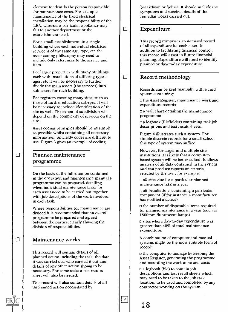
Records can be kept manually with a cardsystem containing:
the Asset Register, maintenance work andexpenditure records
a wall chart detailing the maintenanceprogramme
a logbook (file/folder) containing task jobdescriptions and test result sheets.
Figure 4 illustrates such a system. Forsimple discrete records for a small schoolthis type of system may suffice.
However, for larger and multiple siteinstitutions it is likely that a computer-based system will be better suited. It allowsanalysis of all data contained in the systemand can produce reports on criteriaselected by the user, for example:
all sites due for a particular plannedmaintenance task in a year
all installations containing a particularcomponent (if for instance a manufacturerhas notified a defect)
the number of disposable items requiredfor planned maintenance in a year (such as1800mm fluorescent lamps)
c sites where day-to-day expenditure wasgreater than 40% of total maintenanceexpenditure.
A combination of computer and manualsystems might be the most suitable form ofrecord:
c the computer to manage by keeping theAsset Register, generating the programmeand recording the work done and costs
c a logbook (file) to contain jobdescriptions and test result sheets whichmay need to be taken to the job tasklocation, to be used and completed by anycontractor working on the system.
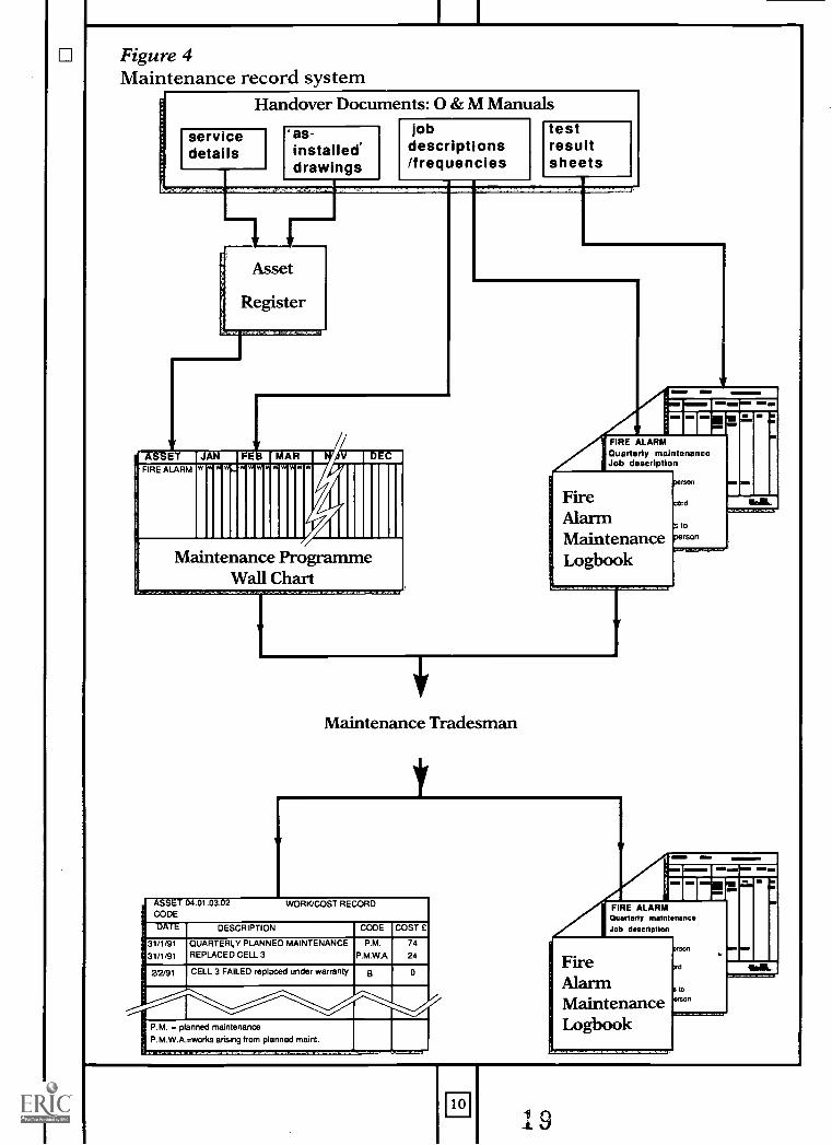
Figure 4Maintenance record system
Handover Documents: 0 & M Manuals
servicedetails
as-installed'drawings
jobdescriptions/frequencies
testresultsheets
Asset
Register
ASSET JAN FE MAR DECFIRE ALARM w w w
Maintenance ProgrammeWall Chart
=IMI al=MMI
FIRE ALARMQuarterly maintenanceJob description
FireAlarmMaintenanceLogbook
mrson
cord
a topersonOnferidisezemr
Maintenance Tradesman
' ASSET 04.01.03.02 WORK/COST RECORDCODE
DATE DESCRIPTION CODE COST £
31/1/91
31/1/91
QUARTERLY PLANNED MAINTENANCEREPLACED CELL 3
P.M.
P.M.W.A.
74
24
2/2/91 CELL 3 FAILED replaced under warranty o 0
P.M. = planned maintenance
P.M.W.A.=works arising from planned maint.
FIRE ALARMQuarterly maintenanceJob descrlellon
10
5 Inspection and testing
KEY POINTSall electrical services need to bemonitored for deterioration
inspection and testing arefundamental to electricalmaintenance
frequencies need to bedetermined by a competentperson
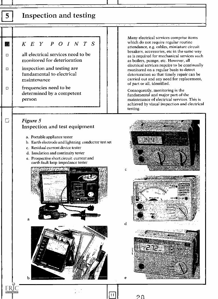
Many electrical services comprise itemswhich do not require regular routineattendance, e.g. cables, miniature circuitbreakers, accessories, etc in the same wayas is required for mechanical services suchas boilers, pumps, etc. However, allelectrical services require to be continuallymonitored on a regular basis to detectdeterioration so that timely repair can becarried out and any need for replacement,of part or all, identified.
Consequently, monitoring is thefundamental and major part of themaintenance of electrical services. This isachieved by visual inspection and electricaltesting.
Figure 5Inspection and test equipment
a. Portable appliance testerb. Earth electrode and lightning conductor test setc. Residual current device testerd. Insulation and continuity testere. Prospective short circuit current and
earth fault loop impedance tester
a
b e
n
Because of the potential danger fromelectricity those responsible formaintenance will have inspection andtesting regimes planned or in place;however, there is a need to explain whythese regimes are necessary and how theycan be continued where responsibilities areto be transferred or divided, for example togovernors who might in turn allow parentsto do some work on a voluntary basis.
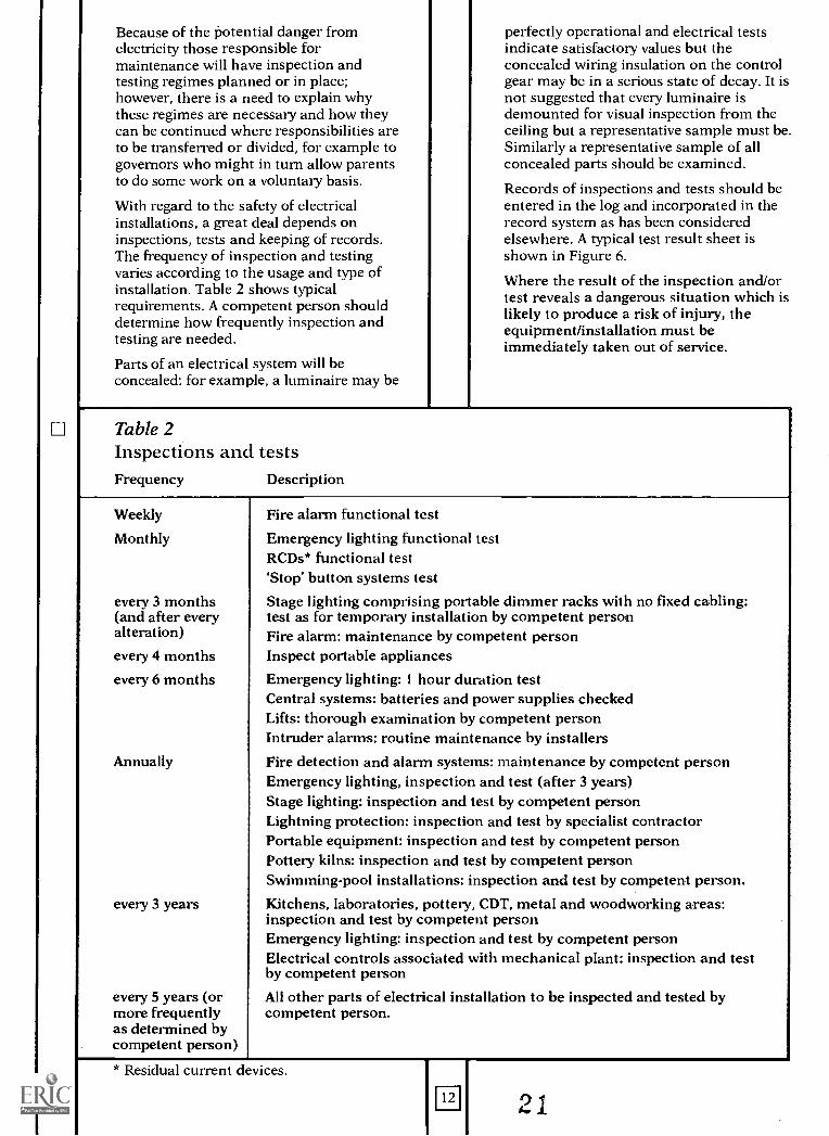
With regard to the safety of electricalinstallations, a great deal depends oninspections, tests and keeping of records.The frequency of inspection and testingvaries according to the usage and type ofinstallation. Table 2 shows typicalrequirements. A competent person shoulddetermine how frequently inspection andtesting are needed.
Parts of an electrical system will beconcealed: for example, a luminaire may be
perfectly operational and electrical testsindicate satisfactory values but theconcealed wiring insulation on the controlgear may be in a serious state of decay. It isnot suggested that every luminaire isdemounted for visual inspection from theceiling but a representative sample must be.Similarly a representative sample of allconcealed parts should be examined.
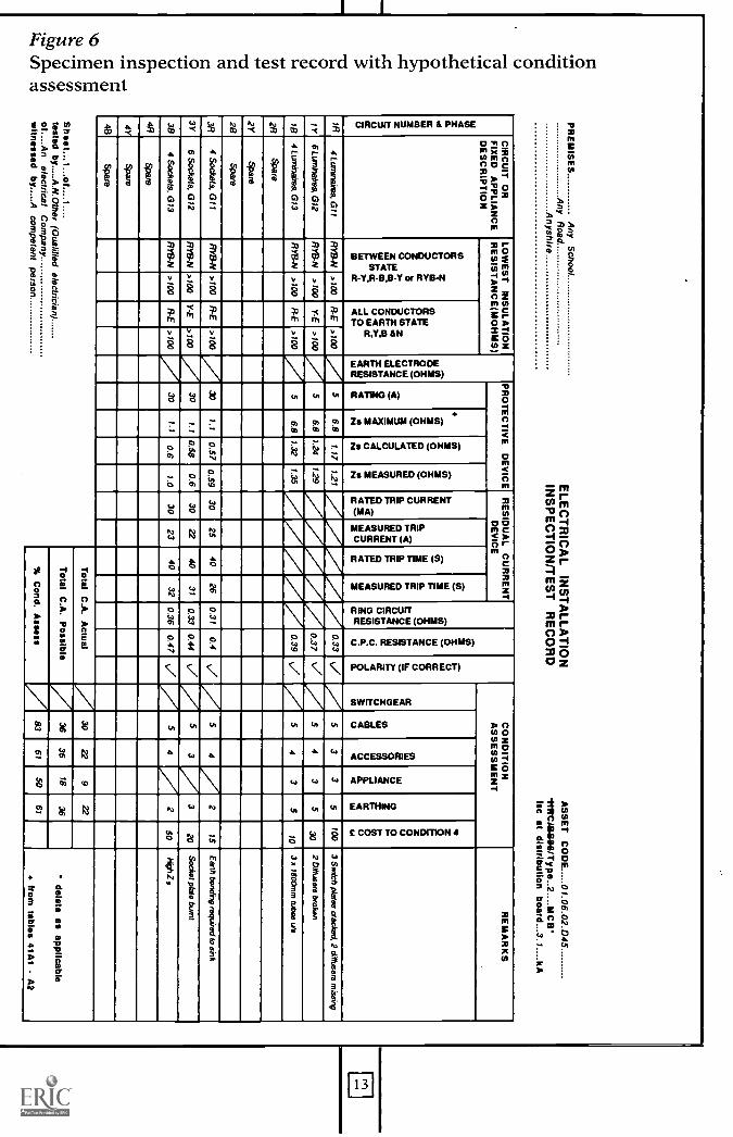
Records of inspections and tests should beentered in the log and incorporated in therecord system as has been consideredelsewhere. A typical test result sheet isshown in Figure 6.
Where the result of the inspection and/ortest reveals a dangerous situation which islikely to produce a risk of injury, theequipment/installation must beimmediately taken out of service.
Tab le 2Inspections and testsFrequency Description
Weekly Fire alarm functional test
Monthly Emergency lighting functional testRCDs* functional test'Stop' button systems test
every 3 months Stage lighting comprising portable dimmer racks with no fixed cabling:(and after every test as for temporary installation by competent personalteration) Fire alarm: maintenance by competent personevery 4 months Inspect portable appliances
every 6 months Emergency lighting: 1 hour duration testCentral systems: batteries and power supplies checkedLifts: thorough examination by competent personIntruder alarms: routine maintenance by installers
Annually Fire detection and alarm systems: maintenance by competent personEmergency lighting, inspection and test (after 3 years)Stage lighting: inspection and test by competent personLightning protection: inspection and test by specialist contractorPortable equipment: inspection and test by competent personPottery kilns: inspection and test by competent personSwimming-pool installations: inspection and test by competent person.
every 3 years Kitchens, laboratories, pottery, CDT, metal and woodworking areas:inspection and test by competent personEmergency lighting: inspection and test by competent personElectrical controls associated with mechanical plant: inspection and testby competent person
every 5 years (or All other parts of electrical installation to be inspected and tested bymore frequentlyas determined bycompetent person)
competent person.
* Residual current devices.
m
PR
EM
ISE
SA
ny School
Any R
oadA
nyshireE
LEC
TR
ICA
L INS
TA
LLAT
ION
INS
PE
CT
ION
/TE
ST
RE
CO
RD
AS
SE
T C
OD
E01.06.02.D
45
-HW
CA
&F
.88/Type..2....M
CB
Isc at distribution board...3. 1.... k A
iii04D.
6CC.,o2z0 'CU
CIR
CU
IT O
RF
IXE
D A
PP
LIAN
CE
DE
SC
RIP
TIO
N
LOW
ES
T IN
SU
LAT
ION
RE
SIS
TA
NC
E(M
OH
MS
)
W i
O g
ug :al.i1-Y2
5 °el 1
PR
OT
EC
TIV
E D
EV
ICE
RE
S D
UA
L CU
RR
EN
TD
EV
ICE
a2ot 11+
(9 2
ou PI
Z ti
EC
-
Vi
2g-la.4P-6C4
0
g111
..gLi.
cFg-j2
CO
ND
ITIO
NA
SS
ES
SM
EN
TR
EM
AR
KS
-si4CC
.6,-;x22.g2iN
322.00I;a4°N
a2x0uticcw3A
I-6ccKD0.1.
04.4
cc -
a....gc4^
01"
rci4(7)1111 =2°
F-,-la2P043
aLu211-ocE
13
001-4
C.,1
0,
,.
I're,
z W ai
ti4 10
M):
CO
IL
0g.4
0 0-8
ffi z2X
40 C
C C
a
d oe1-
¢0Xc.)
k0
inla*0
ewE18.
w24
2Iiu
iRa20g08ia
1R4 Lum
inaires, 211
RY
B-N
>100
RE
>100
56.8
1.17121
0.335
33
5100
3 Sw
itch plates cracked, 2 diffusers msing
1Y6 Luninaires, G
12R
YB
-N>
100Y
-E>
1005
6.81.24
....../1.29
0.374
35
302 D
iffusers broken
784 Lum
inaires, G13
RY
13-N>
100R
-E>
1005
6.81.32
1.35/. /10.39
54
35
703 x 1800m
m tubes o's
2/4Spare
2YS
pare
2BS
pare
384 S
ockets, G11
RY
B-N
>100
R-E
>100
X1.1
0.570.59
3025
4026
0.310.4
V.
54/
215
Eel?) bonding required to sink
3Y6 S
ockets, G12
RY
B-N
>100
Y-E
>100
301.1
0.580.6
3022
4031
0.330.44
53/
320
Socket plate burnt
384 S
ockets, G13
RY
B-N
>100
RE
>100
301.1
0.61.0
3023
4032
0.360.47
54
250
146412,
4RS
pare
rz."
4YS
pare
48S
pare
Sheet.
1. of1.
tested byA
.N.O
ther (Qualified electrician)
of ....An
electrical Com
panyw
itnessed byA
competent person
Total C
.A. A
ctual30
229
22
delete as applicable
from tables 41A
1 - A2
Total C
.A. P
ossible36
3618
36
% C
ond. Assessssess
8361
SO61
ECondition appraisal
KEY POINTSappraisal allows maintenance/replacement to be planned
systematic, uniform and objectivemethods should be adopted
on-the-spot estimates are usefulfor financial planning
Condition appraisal requires some objectivemeasure of the current condition of anasset. With electrical installations theassessment will be carried out by referenceto two sets of information. The first is theresults of inspection by a suitably qualifiedperson of those parts of the installation thatare accessible; it is the nature of electricalinstallations that much is hidden, eitherburied in walls and floors or installedwithin voids, and to maximise safety muchof the installation is deliberatelyinaccessible. The second set of informationis the results of tests designed and carriedout to ascertain the electrical integrity ofthe system as a whole or in part.
This appraisal leads to a determination asto whether the asset, equipment orinstallation is fit for further service orrequires some maintenance, eitherimmediately to avoid danger and risk ofinjury, or at some time in the future. Thatfuture time may be in days, weeks or years.A decision whether to repair or replace anitem of equipment or installation is afurther process determined on practicaland economic grounds.
Where no risk of injury exists it might stillbe economic to repair or replace equipmentto prevent excessive maintenance costs inthe future and forestall breakdown ofequipment. Good records enable suchdecisions to be made objectively.Replacement might also provide anopportunity for the use of more energyefficient equipment. An investmentappraisal of such decisions should alwaysbe made and entered on the records forfuture monitoring.
14
Reference is also made to Building Bulletin70' and Design Note 406. These explainmore fully the basic theory, which isequally applicable to electrical systems.
Life of equipment and systems
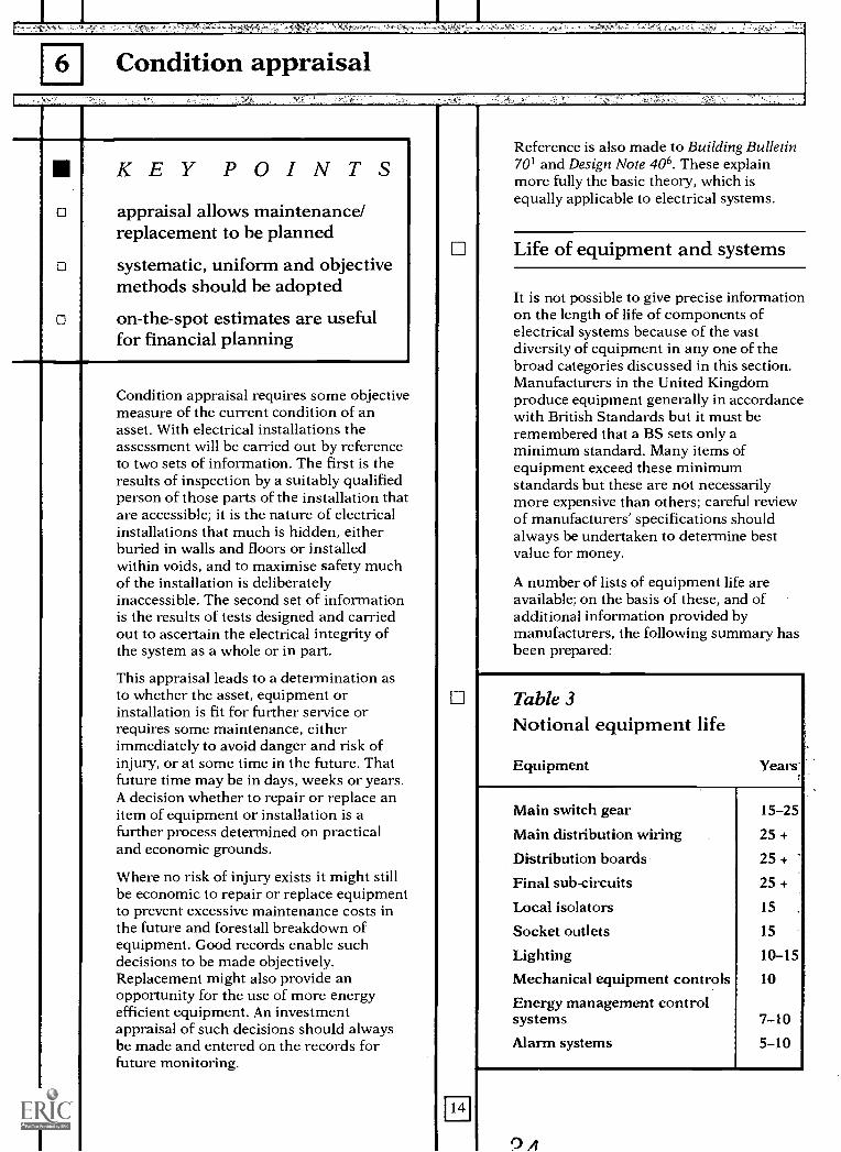
It is not possible to give precise informationon the length of life of components ofelectrical systems because of the vastdiversity of equipment in any one of thebroad categories discussed in this section.Manufacturers in the United Kingdomproduce equipment generally in accordancewith British Standards but it must beremembered that a BS sets only aminimum standard. Many items ofequipment exceed these minimumstandards but these are not necessarilymore expensive than others; careful reviewof manufacturers' specifications shouldalways be undertaken to determine bestvalue for money.
A number of lists of equipment life areavailable; on the basis of these, and ofadditional information provided bymanufacturers, the following summary hasbeen prepared:
Table 3Notional equipment life
Equipment Years
Main switch gear 15-25
Main distribution wiring 25 +
Distribution boards 25 +
Final sub-circuits 25 +
Local isolators 15
Socket outlets 15
Lighting 10-15
Mechanical equipment controls 10
Energy management controlsystems 7-10
Alarm systems 5-10
?A
There can be a considerable differencebetween the maximum life achievable andwhat is economically realistic. In manytypes of electrical equipment, the life isdependent on the number of operations ithas undergone, both under normal loadconditions and under fault conditions; it isthus inappropriate to assign a life in termsof time. The practical difficulty indetermining the number of operations anitem of equipment has undergone may bethe reason that in many cases there is nomaintenance plan and a policy ofbreakdown maintenance is pursued.
Condition assessment
Systematic, uniform and objective methodsshould be adopted for evaluatingmaintenance needs and determiningpriorities, on the basis of the assessedcondition of the electrical services. The aimof the assessment is to provide informationfrom which it should be possible to extractthe data necessary to prepare the plannedmaintenance schedule for up to five years,together with management information forgeneral budgeting and planning.
One of the main criteria for assessment ofthe equipment or system underconsideration is a knowledge of how long itwould take for any item of equipment todeteriorate to a condition which wouldeither pose safety hazards or give rise toother types of trouble under normalconditions of use. It is therefore essential tomonitor and record the condition ofequipment continuously.
It is suggested that the assessment becarried out in conjunction with the routineinspection and test, by the competentperson, and that the assessment is recordedon the composite sheet (see Figure 6). Theinformation which is gathered must be asaccurate as possible whilst at the same timegiving the overall picture of each element;for example the hidden services must beexamined, where possible, not merely givena superficial inspection. However, it shouldbe noted that assessors will not takeunnecessary risks.
Common standards in assessment ofelectrical services are essential. Varyingstandards will result in (widely) differingassessments of needs and result ininconsistency and confused priorities.Where more than one assessor is involvedtechniques should be employed toovercome this, such as regular meetingsbetween assessors to discuss guidelines,
w
particularly where a contractor acts as anassessor as part of the routine inspectionand test.
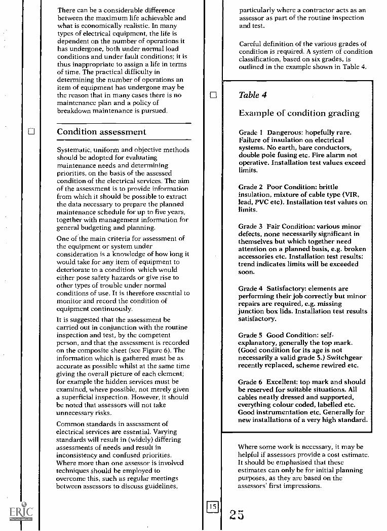
Careful definition of the various grades ofcondition is required. A system of conditionclassification, based on six grades, isoutlined in the example shown in Table 4.
Table 4
Example of condition grading
Grade I Dangerous: hopefully rare.Failure of insulation on electricalsystems. No earth, bare conductors,double pole fusing etc. Fire alarm notoperative. Installation test values exceedlimits.
Grade 2 Poor Condition: brittleinsulation, mixture of cable type (VIR,lead, PVC etc). Installation test values onlimits.
Grade 3 Fair Condition: various minordefects, none necessarily significant inthemselves but which together needattention on a planned basis, e.g. brokenaccessories etc. Installation test results:trend indicates limits will be exceededsoon.
Grade 4 Satisfactory: elements areperforming their job correctly but minorrepairs are required, e.g. missingjunction box lids. Installation test resultssatisfactory.
Grade 5 Good Condition: self-explanatory, generally the top mark.(Good condition for its age is notnecessarily a valid grade 5.) Switchgearrecently replaced, scheme rewired etc.
Grade 6 Excellent: top mark and shouldbe reserved for suitable situations. Allcables neatly dressed and supported,everything colour coded, labelled etc.Good instrumentation etc. Generally fornew installations of a very high standard.
Where some work is necessary, it may behelpful if assessors provide a cost estimate.It should be emphasised that theseestimates can only be for initial planningpurposes, as they are based on theassessors' first impressions.
CMaintenance requirements
KEY POINTSmaintenance needs can bedetermined from adequaterecords
electrical systems last many years
direct replacement may not beeconomic, or appropriate
life-cycle costing allows informeddecisions
Earlier sections have dealt with thenecessity of carrying out regularinspections and tests to assess the safetyand electrical integrity of installations.Given that the primary requirement formaintenance of electrical systems is safety,followed by optimisation of economic life,it is not possible to make preciserecommendations for the inspectionintervals required under all circumstances.
From the records and conditionassessments obtained as part of theinspection and test activities, objectivedecisions can be made and priorities set forthe replacement of equipment that hasreached its economic service life but doesnot pose a danger. Obviously anydangerous conditions revealed in theinspection and test must be attended toimmediately.
Building Bulletin 70' contains a generalisedapproach to these decisions, the variousfactors being considered in detail. Thesame considerations apply to electricalsystems and components. There are furtherfactors directly applicable to electricalsystems.
The nature of the materials used and thecodes of practice which govern electricalinstallations work tend to produceequipment and systems that will last manyyears with little or no maintenancerequirement. An additional factor that willinfluence the repair-or-replace decision isthe system capacity. The use of electricalequipment in teaching has increased
16
dramatically, as has the need for flexibilityin the teaching areas, both of which resultin an increased requirement for electricalpower outlets. This may lead to a decisionto replace with new equipment which willupgrade the system to the latest standardsand will increase the system capacityavailable, even though the old equipmentmay still be repairable.
In many cases replacement or renewal on alike-for-like basis may neither give the bestelectrical service nor be the most cost-effective solution. Integration ofmaintenance and improvement works canensure that work is cost-effective and thatcommon standards are secured.
Part of the evaluation will be aconsideration of life-cycle costs in orderthat an informed decision can be made;and the method and an example areincluded in Appendix I of Building Bulletin70. There are many different methods ofaccounting for costs during the life of anitem of equipment; other examples may befound in the Chartered Institution ofBuilding Services Engineers publicationCIBSE Guides, Section B18: 'Owning andoperating costs'.
It should be borne in mind that a simplerepair of part of a system or item ofequipment is always likely to be initiallycheaper than a repair that involves renewalor replacement. However, replacementcould significantly lower the cost ofmaintaining the system or equipment andintroduce other savings, on energy costs forinstance, or provide other benefits such asgreater capacity or utility. Investmentappraisal of the cost and benefits, not all ofwhich are quantifiable, should enable asound decision to be made.
Maintenance works procedures
0
KEY POINTSpeople involved must becompetent to carry out the task
procedures must ensure thesafety of all
live working should not benecessary in schools
related non-electrical safetymatters must be considered
There are two aspects to maintenancework: the specific maintenance task to beperformed, and the procedure by which thetask is carried out. It is essential to considerthe competence required of personnel whowill carry out electrical maintenance workfrom both viewpoints, and how safety,standards and quality will be ensured.
It must be clearly understood that therequirement for a competent person tocarry out electrical work applies as muchto voluntary work as to paid work.
Technical competence
The extent of work that may be undertakenby school staff is likely to be restricted bytheir technical competence. It will largelybe limited to observation and recording ofinformation, simple functional tests withthe results of the tests being recorded andacted upon, reporting on breakages andbasic safety checks. With adequate trainingthe checking and fitting of plugs andreplacement of failed lamps should bewithin the competence of school staff, butwill depend upon employment conditions.
The use of qualified employees andcontractors is necessary for the majority ofwork. This will generally mean thatoperatives will have completed a recognisedapprenticeship (or other appropriatetraining) and be in possession of somequalifications attesting to their ability. TheElectrical Contractors' Association (ECA),
w
in conjunction with the Electrical,Electronic, Telecommunications andPlumbing Union (EETPU) via their JointIndustry Board (JIB), have defined job titlesand grades of:
LabourerElectricianApproved ElectricianElectrical Technician.
Each operative should be able to provideproof of his or her grade.
In quality terms there are organisationssuch as the National Inspection Council forElectrical Installation Contracting(NICEIC) and the ECA, through whichfirms can be approved; the main objectiveof this approval is to provide anindependent indication of the quality ofworkmanship produced by the employeesand a measure of consumer protection. Anumber of client organisations only usethese approved contractors. A firm mustfulfil a number of requirements before it isapproved, and in the case of many verysmall contracting companies the financialcost may preclude their participation.Objective assessment of small firms is moredifficult and the scope of the work theycould deal with may be limited. However,within their limitations they may well becapable of cost-effective quality work,although an objective method of measuringthe quality must be established and arecord of their work kept.
Procedures
Procedures for carrying out maintenancework must ensure the safety of all, includingthe operative performing the task.
Although planning will ensure that best useis made of holiday periods, much electricalmaintenance work will have to be carriedout while the school is in use. This raisespractical problems such as keeping thework area safe and preventingunauthorised persons from coming intocontact with, or even approaching, liveconductors. This will mean the use ofbarriers to segregate staff and pupils fromwork areas.
r)4.
It is the responsibility of the competentperson in charge of the work to ensure thatthe electricity supplies are securely isolatedbefore and during work. A considerabledanger is an uninformed and unauthorisedperson gaining access to a switchroom orfuse board and energising a circuit thatanother person is working upon; thisproblem is exacerbated when the work areais far from the point of isolation.
Where the LEA is organising work theyshould send formal written notification tothe Head of the school, detailing what workis to be carried out and how it will affectthe premises.
Before any work can be carried out thesafety of the operatives must be ensured:Live working is unlikely to be necessary inschools, with the possible exception of fault-finding on complex control panels, but forwork to be carried out on or near liveconductors, four conditions must besatisfied:i. It is unreasonable in all circumstancesfor the conductor to be dead (de-energised).ii. It is reasonable in all circumstances forthe operative to be at work on or near theconductor whilst it is live.iii. Suitable precautions are taken toprevent injury.iv. The person carrying out the work iscompetent to do so or is under adequatesupervision.
All other work should be carried out whilethe supplies are de-energised and isolated.
In addition to matters directly related to theelectrical services, procedures need to takeaccount of other matters which can arisethrough the carrying out of electricalworks. For example, some school buildingsmay contain asbestos insulation, orasbestos cement partitions or ceilingpanels, and each authority will havedeveloped policies for dealing with them.Some fluorescent luminaires beyond acertain age will very possibly contain poly-chlorinated biphenyls (PCBs) within thecapacitor fitted to the gear tray and need tobe safely disposed of (see Appendix C).
For some works, such as lift maintenance,it will be necessary to ensure the exclusionof all but the maintenance operatives fromthe work area by the erection of barriers.
18
Qkr V
Educational requirements
KEY POINTSplanned maintenance canimprove teaching facilities
safety can be improved
the need for temporary measurescan be obviated
planned maintenance canfacilitate future change
Where possible, maintenance works shouldbe planned and directed, not only toenhance the safety of the installation, butalso to provide for the increasingeducational demands on the electricalinstallation. This section deals briefly withgeneral matters it may be possible toaddress during maintenance.
Curriculum development and use ofinformation technologies have increasedworkplace demands for electricalequipment in the classroom. Many changesin education reflect the increased demands,experienced by businesses and commerce afew years ago, for equipment requiringelectrical and signal cabling. As in thesecases, the use of such equipment improvesthe range of opportunities available ineducation. The keynote in this change isflexibility in the learning spaces, be this informs of teaching, layout of spaces oramount of equipment. This requires anumber of services, particularly theelectrical installation, to be flexible.
Many recent DES Architects and BuildingBranch publications have illustrated thisneed to continually respond to change andinclude guidance for primary, secondaryand tertiary accommodation. The NationalCurriculum is the latest initiative toincrease the need for a flexible, wellserviced learning environment. Architectsand Building Branch plans to publishguidance on the design implications of theindividual subjects of the NationalCurriculum such as Information
19
Technology, Science and Electronics,starting in 1992 with (design) technology.
The problem is often that of insufficientpower outlets within the teaching areasand/or the inappropriate location ofexisting outlets. This applies equally tonormal classroom and specialist areas.
In some establishments there has been aproliferation of extra socket outlets, ofteninstalled on an ad hoc basis. The resultscan be adequate but the provision does notconform to the standards or methods of theremainder of the installation. It would bebetter if flexibility and spare capacity tocater for curriculum needs were built intothe system through design and/or plannedmaintenance, although this type of ad hocpermanent installation work is likely to besafer than extension leads. Appendix Bsuggests socket outlet provision for avariety of spaces and gives advice onaspects of installation. Socket outlets mustbe located for flexibility of use of the spaceand not for ease of installation.
Another solution is the use of extensionleads with a multiple outlet termination,typically four outlets. This providessufficient outlets for most computerstations, which may require an outlet forthe processor and separate outlets for thescreen display, disc drive and printer. Thetotal consumption is well within thecapacity of the fixed installation singlesocket outlet. However, the lead creates adanger of tripping, which could causeinjury or the equipment being pulled off thedesk with resulting costly damage; there isalso the obvious danger that the lead maybecome worn and live conductors exposed.In addition, as the equipment becomesmore mobile with extension leads it may beused in unsafe areas. As this type ofinstallation is temporary in nature itbecomes very difficult to maintain in a safecondition or even keep track of its location.The use of loose extension leads is notrecommended.
However, computer and similar equipmentis often on mobile (wheeled) desks and inthese instances a multiple outlet extensionlead securely fixed to the desk with a shortextensible (curly) cable, and fused at the
ry; rt!oY'
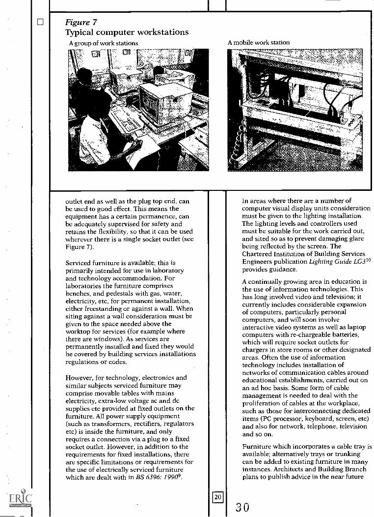
Figure 7Typical computer workstations
A group of work stations
Cie 4111
A mobile work station
r
outlet end as well as the plug top end, canbe used to good effect. This means theequipment has a certain permanence, canbe adequately supervised for safety andretains the flexibility, so that it can be usedwherever there is a single socket outlet (seeFigure 7).
Serviced furniture is available; this isprimarily intended for use in laboratoryand technology accommodation. Forlaboratories the furniture comprisesbenches, and pedestals with gas, water,electricity, etc, for permanent installation,either freestanding or against a wall. Whensiting against a wall consideration must begiven to the space needed above theworktop for services (for example wherethere are windows). As services arepermanently installed and fixed they wouldbe covered by building services installationsregulations or codes.
However, for technology, electronics andsimilar subjects serviced furniture maycomprise movable tables with mainselectricity, extra-low voltage ac and dcsupplies etc provided at fixed outlets on thefurniture. All power supply equipment(such as transformers, rectifiers, regulatorsetc) is inside the furniture, and onlyrequires a connection via a plug to a fixedsocket outlet. However, in addition to therequirements for fixed installations, thereare specific limitations or requirements forthe use of electrically serviced furniturewhich are dealt with in BS 6396: 19909.
20
In areas where there are a number ofcomputer visual display units considerationmust be given to the lighting installation.The lighting levels and controllers usedmust be suitable for the work carried out,and sited so as to prevent damaging glarebeing reflected by the screen. TheChartered Institution of Building ServicesEngineers publication Lighting Guide LG31°provides guidance.
A continually growing area in education isthe use of information technologies. Thishas long involved video and television; itcurrently includes considerable expansionof computers, particularly personalcomputers, and will soon involveinteractive video systems as well as laptopcomputers with re-chargeable batteries,which will require socket outlets forchargers in store rooms or other designatedareas. Often the use of informationtechnology includes installation ofnetworks of communication cables aroundeducational establishments, carried out onan ad hoc basis. Some form of cablemanagement is needed to deal with theproliferation of cables at the workplace,such as those for interconnecting dedicateditems (PC processor, keyboard, screen, etc)and also for network, telephone, televisionand so on.
Furniture which incorporates a cable tray isavailable; alternatively trays or trunkingcan be added to existing furniture in manyinstances. Architects and Building Branchplans to publish advice in the near future
0
on the special servicing and furnishingaspects of the use of informationtechnology in educational establishments.Similar regulations to those for electricalpower apply to low voltagecommunications cabling and a responsibleattitude to cable management must bedeveloped, learning from the costly pitfallsexperienced in the business community.Circuits supplying a number of computersshould comply with Section 607 of the IEEWiring Regulations" with respect to earthleakage currents.
Science departments increasingly rely onelectrical power for the new initiatives, andagain the opportunities should be takenduring major maintenance (or adaptation)to improve the safety of these systems. Ahigher standard of electrical protection canbe achieved through the use of residualcurrent devices (RCDs), 1:1 isolatingtransformers, or earth free areas. The HSEproduce a Guidance Note12 which includesadvice on these matters; the Consortia ofLocal Education Authorities for theProvision of Science in Schools (CLEAPSS)have also produced guidance13.
Food areas, where electrical outlets are inclose proximity to general damp and waterand where there is likely to be muchextraneous metalwork, require particularattention to earth and equipotentialbonding. RCD protection should be astrong consideration. It is likely that morethan half the number of cookers will beelectric; careful consideration will need tobe given to the means of getting electricitysupplies to them. The numbers and sizes ofcables will necessitate a large cabletrunking; alternatively, it may be beneficialto use busbar trunking to facilitate futurechange. Table top cookers rated at less than3kW should be permanently wired to afused outlet; larger cookers rated at morethan 3 kW should have a dedicated supply.
Music departments are using ever-increasing amounts of electrical equipmentsuch as keyboards and synthesizers etc andneed generous socket outlet provision.Power requirements are likely to beminimal, but large numbers of sockets willbe needed. Dedicated ring circuits withtwin socket outlets at regular intervalsaround the perimeter of the music roomwill be sufficient. Practice rooms needample provision as they may containextensive electrical equipment such asmixers, equalisers, tape decks and personalcomputers.
m
Facilities for drama studies need carefulconsideration, in particular when providingstage lighting installations. Staff andstudents will be in close contact withelectrical systems when altering lightingarrangements to suit different sets.Consequently safety features such as RCDs,permanent wiring of as much of theinstallation as practical to minimisetemporary wiring, and other measures areof paramount importance.
Certain statutory regulations, such as theCOSHH Regulations, will require theinstallation of extra electrically drivenequipment such as local exhaust ventilation(LEV). According to the COSHHRegulations, LEV must be regularlymaintained and records kept of work done.
It is a requirement of licensing authoritiesthat for public performances the powersupplies for the performers' equipmentmust be protected by RCDs. This is a directresult of a number of fatal accidents causedby poorly maintained equipment. There isno evidence that equipment of this type inthe education sector is any bettermaintained, and a policy of fitting RCDs inall halls in educational premises should beadopted, if the hall is to be used for publicperformances, discos etc.
When providing showers it should be bornein mind that some LEAs have reported thatthey have been advised by the HSE of theneed to install earth equipotentially bondedmetallic grids set within the concrete floorof showers for premises with protectivemultiple earth (PME) electricity supplies.
31
10 Energy
KEY POINTSenergy savings are possiblethrough maintenance
establishments are nowresponsible for energy costs
lighting is a major consumer ofenergy
electric controls save other formsof energy
One common problem is that in manyestablishments energy invoices are settledand priorities for energy conservation workset separately from the planning andcarrying out of maintenance works.Expenditure on maintenance has a directlink to expenditure on energy. One of theprime objectives of maintenance should beto promote energy efficiency.
This division of responsibility increases therisk of duplication of effort and removessome of the motivation for the inclusion ofenergy-saving measures with maintenancework.
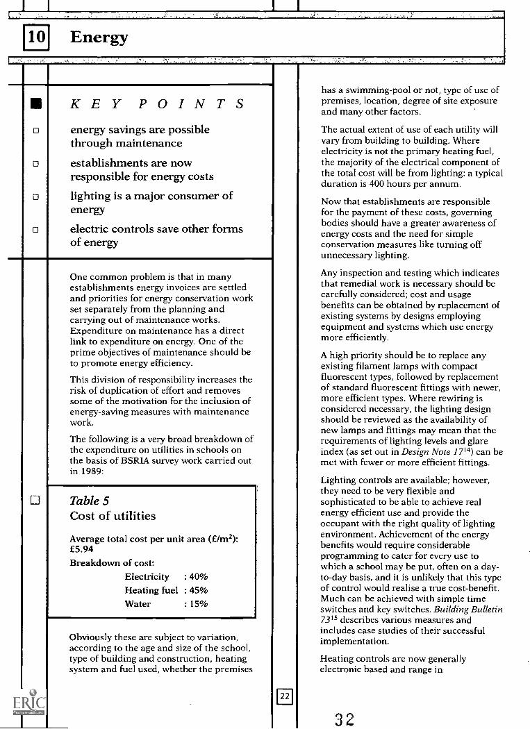
The following is a very broad breakdown ofthe expenditure on utilities in schools onthe basis of BSRIA survey work carried outin 1989:
Table 5Cost of utilities
Average total cost per unit area (£/m2):£5.94Breakdown of cost:
Electricity : 40%Heating fuel : 45%
Water : 15%
Obviously these are subject to variation,according to the age and size of the school,type of building and construction, heatingsystem and fuel used, whether the premises
El
has a swimming-pool or not, type of use ofpremises, location, degree of site exposureand many other factors.
The actual extent of use of each utility willvary from building to building. Whereelectricity is not the primary heating fuel,the majority of the electrical component ofthe total cost will be from lighting: a typicalduration is 400 hours per annum.
Now that establishments are responsiblefor the payment of these costs, governingbodies should have a greater awareness ofenergy costs and the need for simpleconservation measures like turning offunnecessary lighting.
Any inspection and testing which indicatesthat remedial work is necessary should becarefully considered; cost and usagebenefits can be obtained by replacement ofexisting systems by designs employingequipment and systems which use energymore efficiently.
A high priority should be to replace anyexisting filament lamps with compactfluorescent types, followed by replacementof standard fluorescent fittings with newer,more efficient types. Where rewiring isconsidered necessary, the lighting designshould be reviewed as the availability ofnew lamps and fittings may mean that therequirements of lighting levels and glareindex (as set out in Design Note 1714) can bemet with fewer or more efficient fittings.
Lighting controls are available; however,they need to be very flexible andsophisticated to be able to achieve realenergy efficient use and provide theoccupant with the right quality of lightingenvironment. Achievement of the energybenefits would require considerableprogramming to cater for every use towhich a school may be put, often on a day-to-day basis, and it is unlikely that this typeof control would realise a true cost-benefit.Much can be achieved with simple timeswitches and key switches. Building Bulletin7315 describes various measures andincludes case studies of their successfulimplementation.
Heating controls are now generallyelectronic based and range in
32
sophistication. Good practice suggests thata single control thermostat will work onlyin small premises. In a school environmentthe sensors must be such that they areimmune to tampering and adjustment byunauthorised persons. As with lightingcontrols, they may require some re-programming to cater for variations in day-to-day usage; however, an assumption mustbe made that the site staff have littletechnical expertise, so this programmingmust be kept to a minimum. Generally,environmental controls will achieve costbenefits only if they are correctlyprogrammed and calibrated, therefore theymust be regularly maintained. This cangenerally be done only by trained personnelsuch as a specialist contractor. This servicecost must be regarded as an investment toprevent costly energy wastage.
The changes in the electricity supplyindustry and their tariff structures willaffect all premises in due course; theseshould always be kept under review,especially where there are electric heatingsystems.
Many premises are likely to be charged forelectricity on a maximum demand tariff,where costs are based on the highestelectrical demand register over any half-hour period. For some tariffs thismaximum demand will be used in thecalculations of energy accounts for a year;for others it will be used for a shorterperiod, but still for months. Thus, if aportable heater is used for half-an-hour at atime of peak demand, additional demandcharges will be incurred for a periodwhether the heater is used again or not.Therefore, wherever possible the use ofelectricity should be spread to minimisedemand and hence costs; for example byusing large electrical loads, such as kilns,one at a time rather than simultaneously.Stage lighting should preferably not beused at all at times of peak demand, and inany event any lanterns no longer requiredshould be turned off before turning onothers. Equipment not requiringsupervision could be put on timed suppliesto operate overnight.
Awareness of Legionnaires' disease and thepotential for hot water systems to becomeinfected if allowed to operate at lowtemperatures have an effect on energycosts. However, systems are often being runat excessively high temperatures. There isof course a need to ensure protection of theoccupants from scalding if the water is toohot; and there will be increased energy
losses through higher storage anddistribution temperatures. In maintenanceof domestic hot water systems,consideration should be given todecentralising water heating plant orinstalling instantaneous water heaters atthe point of use. The point should be madethat some schools may have special tariffstructures associated with kitchens and hotwater, which might be affected by installingelectric point-of-use heaters.
Apart from a zone approach for bothlighting and heating controls, considerationshould also be given to the installation ofmore detailed metering of both heat andelectricity consumption, particularly if thepremises are used by other organisationsoutside normal school hours. This detailedmetering would help in energymanagement by the school's staff in theearly identification of poor control, as wellas allowing accurate cost recovery fromother users. However, a cost-benefitevaluation must be undertaken.
As well as energy consumption, waterconsumption can be a large proportion ofthe total utility costs, and thereforeconsideration should be given to the manyelectrically powered water saving devices,such as variable time period flushing ofurinals, the frequency being increased tocoincide with peaks in their usage.
491 -17i,+ [fl ,C6Pi
11 Community usetv41;1,1- 311.t.:;1- Iht. itzi-zT,,,.11;'4 11 istfj% 349.0112, k lf.ar 341
KEY POINTSfacilities are being increasinglyused by the community
safety should always be thehighest priority
additional services/zoning ofservices may be required
Increasingly, school facilities are beingused outside normal hours for communityuse. These uses include PTAs for social andsports activities, for adult educationcourses, or for religious use, pollingstations or other community activities.
As governing bodies gain increasing or totalcontrol over the running of their premises,some may plan to increase their useparticularly for recreational purposes.Some method of ensuring the safety ofequipment brought in, and use ofpermanent installations, is needed.
The safety of facilities, whilst always thehighest priority, is particularly importantwhen they are to be used by members of
the public not familiar with them.Arrangements, clearly understood by allparties, are needed to ensure safetystandards are maintained.
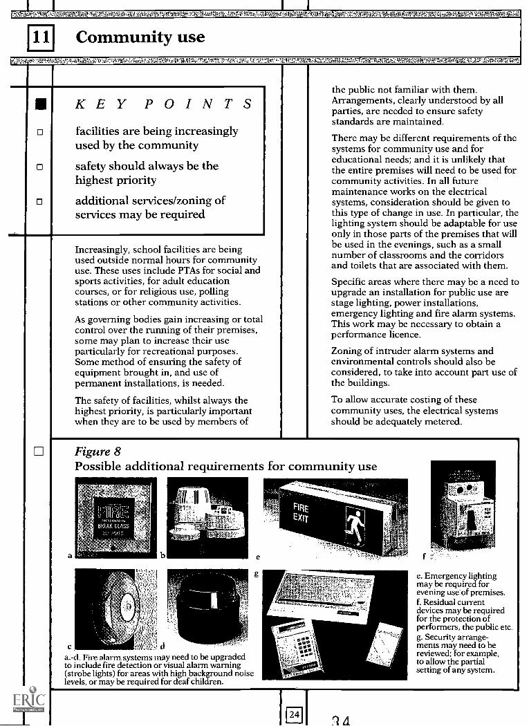
There may be different requirements of thesystems for community use and foreducational needs; and it is unlikely thatthe entire premises will need to be used forcommunity activities. In all futuremaintenance works on the electricalsystems, consideration should be given tothis type of change in use. In particular, thelighting system should be adaptable for useonly in those parts of the premises that willbe used in the evenings, such as a smallnumber of classrooms and the corridorsand toilets that are associated with them.
Specific areas where there may be a need toupgrade an installation for public use arestage lighting, power installations,emergency lighting and fire alarm systems.This work may be necessary to obtain aperformance licence.
Zoning of intruder alarm systems andenvironmental controls should also beconsidered, to take into account part use ofthe buildings.
To allow accurate costing of thesecommunity uses, the electrical systemsshould be adequately metered.
Figure 8Possible additional requirements for community use
a
a.-d. Fire alarm systems may need to be upgradedto include fire detection or visual alarm warning(strobe lights) for areas with high background noiselevels, or may be required for deaf children.
e
g
RV?
al=121.1
24
f
e. Emergency lightingmay be required forevening useof premises.f. Residual currentdevices may be requiredfor the protection ofperformers, the public etc.g. Security arrange-ments may need to bereviewed; for example,to allow the partialsetting of any system.
12 Flexibility and spare capacity
0
0
KEY POINTSelectrical services have very longlives
flexibility and expandability(spare capacity) will extenduseful life
spare capacity is not necessarilycostly
In the past there has been less need for theuse of electricity for teaching, and often theexisting distribution and location of thesmall power installation are nowinappropriate. Maintenance should,wherever possible, take account of thepotential increase in loading together withthe distribution, number and type ofconsumer points (socket outlets or similar).
As has been noted, the flexibility requiredof teaching spaces has increased in recentyears with the greater use of computers andother audio-visual and electronic teachingaids.
As has also been noted, to allowimprovement in the energy efficient use ofbuildings, the building services need toallow the user to be selective in the use ofthe services to correspond with partialoccupancy of the premises, particularly forcommunity use.
The products used in electrical installationare of an inherently durable nature. Thereare many examples of PVC insulated cablestill in use after 30 years with no obvioussigns of deterioration, with every possibilitythat it could still be serviceable for manyyears to come. Most distribution switchgearis infrequently operated and, provided it isnot subjected to overload or fault currents,it will remain serviceable for many years.Electrical control equipment such as relaysand contactors have lives measured inthousands of operations. This durablenature means that an installation can lastfor a considerable time, even though other
Eli
factors will change with regard to the useand capacity of the equipment.
Changes in the curriculum, particularlycraft, design and technology and use ofcomputers, are placing a greater demandupon the existing installations. For thisreason, and because of changes in safetystandards over a number of years, parts ofthe electrical systems are quite oftenextended or equipment replaced eventhough it is technically still serviceable.
It is considered unlikely that all areas of aschool will be able to be used for allteaching activities, and therefore, carefulattention must be given to the provision forspecialist areas such as:
computerssciencescookerycraft, design and technologymusic.
These areas will have particularrequirements of the electrical systems forthe provision of:
communication networkscontactor-controlled safety stop systemsaudio, radio and television circuitsspecialist lighting.
All planned maintenance work and someunplanned work should be carried out witha view to providing greater flexibility of thesystems, to allow for changes in teachingmethods and subjects, as well as moregeneral use of the buildings.
Any planned maintenance work which willinvolve the replacement of parts should bedesigned so as to allow for higher demandsin future, while keeping within reasonablecost constraints. An additional 25%capacity in the electrical installation shouldprovide for reasonable expansion withoutincurring undue costs.
While a short-term drop in school rolls mayresult in the rationalisation of buildingsand sites, the durable nature of electricalinstallations requires that a long-term viewshould be taken. This may be a simpledecision to use conduit rather than mineralinsulated copper covered (MICC) cable and
35
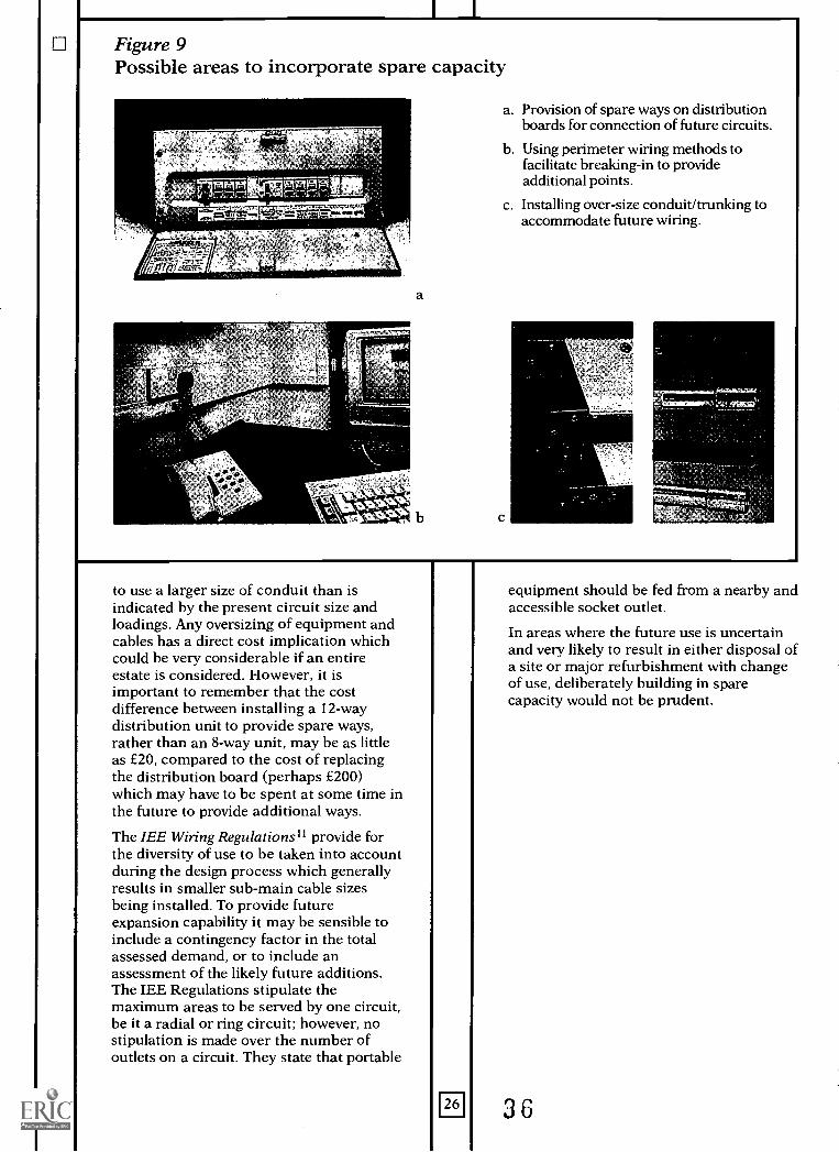
Figure 9Possible areas to incorporate spare capacity
cell? cr. wirer,r,
a
a. Provision of spare ways on distributionboards for connection of future circuits.
b. Using perimeter wiring methods tofacilitate breaking-in to provideadditional points.
c. Installing over-size conduit/trunking toaccommodate future wiring.
to use a larger size of conduit than isindicated by the present circuit size andloadings. Any oversizing of equipment andcables has a direct cost implication whichcould be very considerable if an entireestate is considered. However, it isimportant to remember that the costdifference between installing a 12-waydistribution unit to provide spare ways,rather than an 8-way unit, may be as littleas £20, compared to the cost of replacingthe distribution board (perhaps £200)which may have to be spent at some time inthe future to provide additional ways.
The IEE Wiring Regulationsil provide forthe diversity of use to be taken into accountduring the design process which generallyresults in smaller sub-main cable sizesbeing installed. To provide futureexpansion capability it may be sensible toinclude a contingency factor in the totalassessed demand, or to include anassessment of the likely future additions.The IEE Regulations stipulate themaximum areas to be served by one circuit,be it a radial or ring circuit; however, nostipulation is made over the number ofoutlets on a circuit. They state that portable
26
equipment should be fed from a nearby andaccessible socket outlet.
In areas where the future use is uncertainand very likely to result in either disposal ofa site or major refurbishment with changeof use, deliberately building in sparecapacity would not be prudent.
36
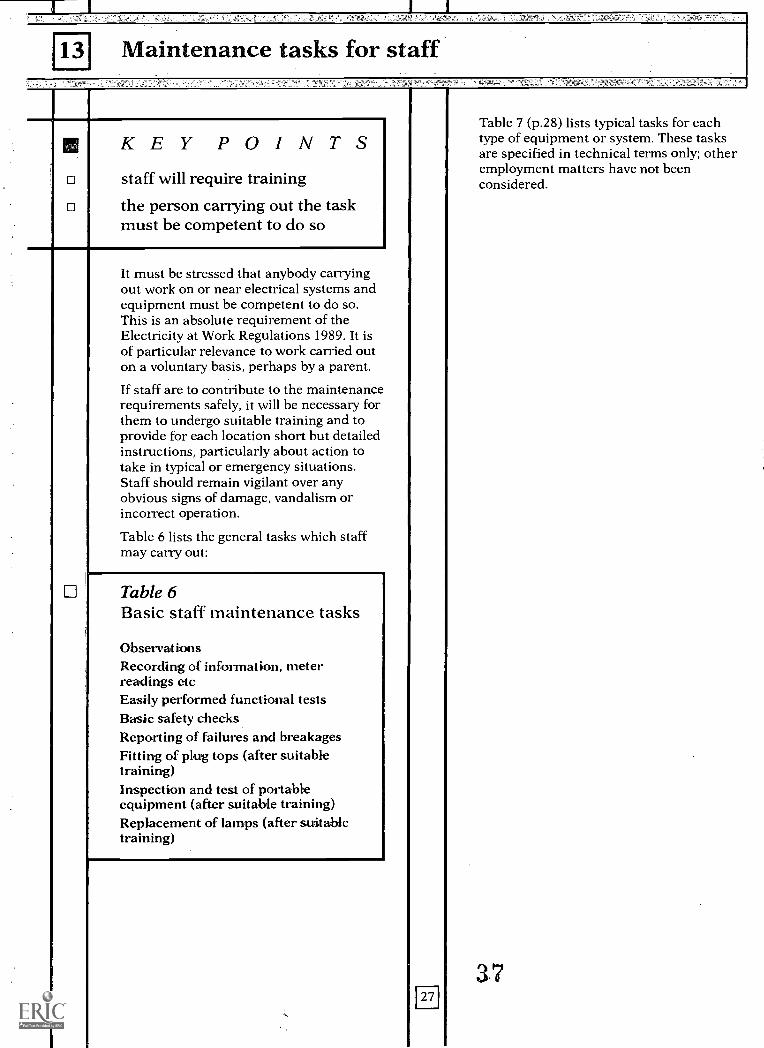
131 Maintenance tasks for staff
KEY POINTSstaff will require training
the person carrying out the taskmust be competent to do so
It must be stressed that anybody carryingout work on or near electrical systems andequipment must be competent to do so.This is an absolute requirement of theElectricity at Work Regulations 1989. It isof particular relevance to work carried outon a voluntary basis, perhaps by a parent.
If staff are to contribute to the maintenancerequirements safely, it will be necessary forthem to undergo suitable training and toprovide for each location short but detailedinstructions, particularly about action totake in typical or emergency situations.Staff should remain vigilant over anyobvious signs of damage, vandalism orincorrect operation.
Table 6 lists the general tasks which staffmay carry out:
Table 6Basic staff maintenance tasks
ObservationsRecording of information, meterreadings etcEasily performed functional testsBasic safety checksReporting of failures and breakagesFitting of plug tops (after suitabletraining)Inspection and test of portableequipment (after suitable training)Replacement of lamps (after suitabletraining)
Eil
Table 7 (p.28) lists typical tasks for eachtype of equipment or system. These tasksare specified in technical terms only; otheremployment matters have not beenconsidered.
3.7

Table 7Possible staff maintenance tasks (after suitable training)
Equipment or System Task
Main switchgear
Distribution wiring
Distribution boards
Final subcircuits
Lighting: stagemain
emergencyControl systems
Mechanical servicescontrols
Fire alarms
Intruder alarms
Portable equipment
Lightning protectionLifts
Inspection of switchgear/switch room on daily basis with emphasison cleanliness, potential hazards such as water leakage, abnormalnoise or overheating and security of the location.
2 Record meter readings for energy analysis by others. Look for anyindicating lights that have changed status/appear to have failed,check the actual status if possible and take appropriate action.
3 Carry out any functional safety tests such as checking RCD self testevery month.
4. Provide assistance to maintenance contractors whilst on site. Thiscould involve remaining with the contractor's operative whilst workis carried out and will certainly entail providing access to securedareas such as switchrooms.
1 Observation for mechanical damage and reporting back ofproblems. Particular attention should be paid to equipotentialearth bonding.
2 Providing maintenance operatives with any personally knowninformation.
1 Check to ensure security, functional test of RCD test button orother safety system.Observation and reporting of faulty or damaged circuit accessorieslike socket outlets, light switches etc. Switching off/making safedamaged equipment.
1. Alteration to installation of lamps etc.1. Isolation of lighting circuit and replacement of lamps. This could
be either a simple replacement on failure or a bulk relamping.2. Cleaning of diffuser/controller, in conjunction with Item 1.3. Disposal of small quantities of failed lamps.1. Regular functional testing and recording of tests.1. Programming of controls for different uses of building.2. Changing over from British Summer Time to Greenwich Mean
Time and vice versa.3. Resetting time switch after power failure.4. Noting and reporting of faults.5. Recording of energy readings.6. Overriding of system/manual control.1. Cleaning exterior of cabinets.2. Simple functional tests.3. Simple safety tests.4. Recording of plant settings and energy information.5. Setting and overriding of time switches.1. Daily inspection of control panel.2. Recording and reporting faults.3. Weekly test, each initiation point to be checked every 13 weeks.1. Setting and turning off system.2. Identification of simple zone faults.3. Maintain secure, accurate records.4. Partial setting to allow out-of-hours use.1. Fitting of plugs.2. Brief visual inspection each time equipment is used.3. Record keeping associated with annual inspection and test.1. Observation and report of damage.1. Observation and report of damage.2. Simple safety and functional tests.
28
3 8
EN IICF4S
39
FA1APPENDIX AGuidance to governing bodies
The responsibilities of governing bodies forelectrical maintenance have increased inrecent years and now range from a partialresponsibility under LMS, where there is adivision of maintenance responsibilitiesbetween the establishment management(e.g. governors and/or teaching staff) andLEAs, to complete responsibility for grant-maintained establishments and CityTechnology Colleges. This appendix seeksto provide guidance for governing bodieswho have full maintenance responsibilities.
Safety
An absolute requirement of the Electricityat Work Act (1989) is that anybodycarrying out work on or near electricalservices is competent to do so.
The headteacher and governing bodyshould ensure that:
design of electrical installations for newbuildings, extensions and alterations, andthe assessment of the maintenancerequirements are carried out by a qualifiedengineer.
actual installation work, maintenancework, and the design of minor works arecarried out by a qualified electrician.
staff asked to carry out any electricalwork, even a simple task like fitting a plug,are properly trained.
Maintenance requirement
It is essential that a qualified engineer hasassessed the total maintenance requirementof the establishment and has documentedit. Where there is a division ofresponsibilities these must be documentedand clearly understood.
The maintenance requirement must bearranged to show the level of competencerequired for each aspect or task:
a. Those aspects for which specialistmaintenance staff (e.g. qualified electrician)will be needed (e.g. testing).
30
b. Those which may be carried out byschool staff after technical training (e.g.installing a plug).
c. Those which may be carried out by staffwithout technical training (e.g. routine firealarm tests).
Particular aspects that staff are likely to beresponsible for, after appropriate training,include the routine inspection andfunctional testing of:
portable equipment
fire alarms
emergency lighting
residual current devices
stage lighting.
Table 2 (p.12) and Table 6 (p.27) givefurther guidance.
Staff must be encouraged to remain vigilantover any obvious signs of damage,vandalism, incorrect operation, etc; systemsmust be in place for these matters to bereported for corrective maintenance actionto be initiated.
Maintenance programme
All work must be planned to ensure safeworking procedures, to ensure the safety ofthe operative, staff and pupils in the school.
Planning allows for all the opportunities forimprovement and energy conservation to betaken during maintenance, and formaintenance items to be grouped wherepossible to make them more economic.
Systems must be in place to ensure thatroutine inspection and testing takes place atthe intervals detailed elsewhere in thisBulletin, by staff /competent people asappropriate, and to confirm that all testcertificates etc. are current.
Where work has to be carried out bycontractor, the programme must initiatemaintenance action required includingtendering or renewing of specialistmaintenance contracts. Schools may find iteconomic and convenient to let a 'termcontract' for maintenance work in their
an
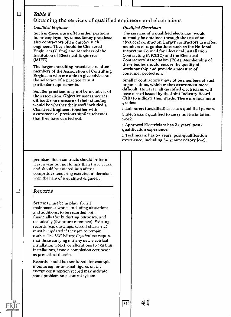
Table 8Obtaining the services of qualified engineers and electriciansQualified EngineerSuch engineers are often either partnersin, or employed by, consultancy practices.;also contractors often employ suchengineers. They should be CharteredEngineers (C.Eng) and Members of theInstitution of Electrical Engineers(MIEE)..
The larger consulting practices are oftenmembers of the Association of ConsultingEngineers who are able to give advice onthe selection of a practice to suitparticular requirements.
Smaller practices may not be members ofthe association. Objective assessment isdifficult; one measure of their standingwould be whether their staff included aChartered Engineer, together withassessment of previous similar schemesthat they have carried out.
Qualified Electrician.The services of a qualified electrician wouldnormally be obtained through the use of anelectrical contractor. Larger contractors are oftenmembers of organisations such as the NationalInspection Council for Electrical InstallationContracting (NICEIC) and the ElectricalContractors' Association (ECA). Membership ofthese bodies should ensure the quality ofworkmanship and provide a measure ofconsumer protection.
Smaller contractors may not be members of suchorganisations, which makes assessment moredifficult. However, all qualified electricians willhave a card issued by the Joint Industry Board(JIB) to indicate their grade. There are four maingrades:L1Labourer: (unskilled) assists a qualified person.f.3 Electrician: qualified to carry out installationworkC3 Approved Electrician: has 2+ years' post-qualification experience.o Technician: has 5+ years' post-qualificationexperience, including 3+ at supervisory level.
premises. Such contracts should be for atleast a year but not longer than three years,and should be entered into after acompetitive tendering exercise, undertakenwith the help of a qualified engineer.
Records
Systems must be in place for allmaintenance works, including alterationsand additions, to be recorded bothfinancially (for budgeting purposes) andtechnically (for future reference). Existingrecords (e.g. drawings, circuit charts etc)must be updated if they are to remainusable. The IEE Wiring Regulations requirethat those carrying out any new electricalinstallation works, or alterations to existinginstallations, issue a completion certificateas prescribed therein.
Records should be monitored; for example,monitoring for unusual figures on theenergy consumption record may indicatesome problem on a control system.
m 41.
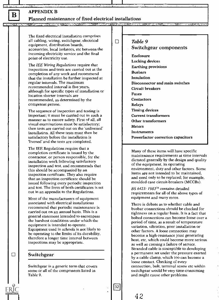
BAPPENDIX B
Planned maintenance of fixed electrical installations
The fixed electrical installation comprisesall cabling, wiring, switchgear, electricalequipment, distribution boards,accessories, local isolators, etc between theincoming electricity service and the finalpoint of electricity use.
The IEE Wiring Regulations require thatinspections and tests are carried out at thecompletion of any work and recommendthat the installation be further inspected atregular intervals. The maximumrecommended interval is five years,although for specific types of installation orlocation shorter intervals arerecommended, as determined by thecompetent person.
The sequence of inspection and testing isimportant; it must be carried out in such amanner as to ensure safety. First of all, allvisual examinations must be satisfactory;then tests are carried out on the 'unlivened'installation. All these tests must then besatisfactory before the installation is'livened' and the tests are completed.
The IEE Regulations require that acompletion certificate is issued by thecontractor, or person responsible, for theinstallation work following satisfactoryinspection and test, and recommends thatthis should be accompanied by aninspection certificate. They also requirethat an inspection certificate should beissued following every periodic inspectionand test. The form of both certificates is setout in an appendix to the Regulations.
Most of the manufacturers of equipmentassociated with electrical installationsrecommend that periodic maintenance iscarried out on an annual basis. This is ageneral statement intended to encompassthe harshest conditions under which theequipment is intended to operate.Equipment used in schools is not likely tobe operating to the limits of its durability,therefore a longer time interval betweeninspections may be appropriate.
Switchgear
Switchgear is a generic term that coverssome or all of the components listed inTable 9.
Table 9Switchgear componentsEnclosureLocking devicesEarthing provisionsBusbarsInsulationDisconnector and main switchesCircuit breakersFusesContactorsRelaysTiming devicesCurrent transformersOther transformersMetersInstrumentsPowerfactor correction capacitors
Many of these items will have specificmaintenance requirements at time intervalsdictated generally by the design and qualityof the equipment, its operatingenvironment, duty and other factors. Someitems are not intended to be maintained,and need only to be replaced; for example,moulded case circuit-breakers (MCCBs).
BS 6423: 198316 contains detailedrequirements for all of the above types ofequipment and many more.
There is debate as to whether cable andbusbar connections should be checked fortightness on a regular basis. It is a fact thatbolted connections can become loose over aperiod of time, as a result of temperaturevariation, vibration, poor installation orother factors. A loose connection maybecome a high-resistance joint generatingheat, etc, which could become more seriousas well as causing a failure of service.Stranded cable is susceptible to developinga permanent set under the pressure exertedby a cable clamp, which too can become aloose contact. Checking of everyconnection, bolt, terminal screw etc withinswitchgear would be very time-consumingand might cause other problems.
4 2
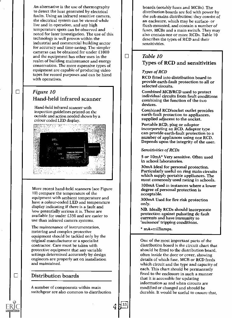
An alternative is the use of thermographyto detect the heat generated by electricalfaults. Using an infrared sensitive camera,the electrical system can be viewed whilelive and in operation, and any hightemperature spots can be observed andnoted for later investigation. The use of thistechnology is well proven within theindustrial and commercial building sectorfor accuracy and time-saving. The simplercameras can be obtained for under £1000and the equipment has other uses in therealm of building maintenance and energyconservation. The more expensive types ofequipment are capable of producing videotapes for record purposes and can be hiredwith operatives.
Figure 10Hand-held infrared scannerHand-held infrared scanner withinspection guidelines printed on theoutside and action needed shown by acolour coded LED display.
More recent hand-held scanners (see Figure10) compare the temperature of theequipment with ambient temperature andhave a colour-coded LED and temperaturedisplay indicating if there is a fault andhow potentially serious it is. These areavailable for under £350 and are easier touse than infrared camera systems.
The maintenance of instrumentation,metering and complex protectiveequipment should be tackled only by theoriginal manufacturer or a specialistcontractor. Care must be taken withprotective equipment that any variablesettings determined accurately by designengineers are properly set on installationand maintained.
Distribution boards
A number of components within mainswitchgear are also common to distribution
boards (notably fuses and MCBs). Thedistribution boards are fed with power bythe sub-mains distribution; they consist ofan enclosure, which may be surface- orflush-mounted, and contain a number offuses, MCBs and a main switch. They mayalso contain one or more RCDs. Table 10describes the types of RCD and theirsensitivities.
Table 10Types of RCD and sensitivities
Types of RCDRCD fitted into distribution board toprovide earth-fault protection to all orselected circuits.Combined MCB/RCD used to protectindividual circuits from fault conditionscombining the function of the twodevices.Combined RCD/socket outlet providesearth-fault protection to appliances,supplied adjacent to the socket.Portable RCD, plug or adaptorincorporating an RCD. Adaptor typecan provide earth-fault protection to anumber of appliances using one RCD.Depends upon the integrity of the user.
Sensitivities of RCDs
5 or 10mA* Very sensitive. Often usedin school laboratories.30mA Ideal for personal protection.Particularly useful on ring main circuitswhich supply portable appliances. Themost commonly used rating in schools.100mA Used in instances where a lowerdegree of personal protection isacceptable.300mA Used for fire risk protectiononly.NB. Ideally RCDs should incorporateprotection against pulsating dc faultcurrents and have immunity to'nuisance' tripping conditions.
* xnA=milliamps.
One of the most important parts of thedistribution board is the circuit chart thatshould be fitted to the distribution board,often inside the door or cover, showingdetails of which fuse, MCB or RCD feedswhich circuit and the type and capacity ofeach. This chart should be permanentlyfixed to the enclosure in such a mannerthat it is accessible for updatinginformation as and when circuits aremodified or changed and should bedurable. It would be useful to ensure that,
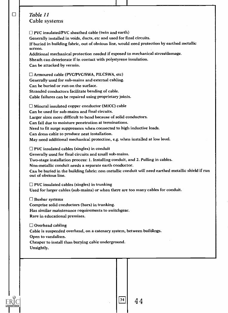
Table 11Cable systems
LI PVC insulated/PVC sheathed cable (twin and earth)Generally installed in voids, ducts, etc and used for final circuits.If buried in building fabric, out of obvious line, would need protection by earthed metallicscreen.Additional mechanical protection needed if exposed to mechanical stress/damage.Sheath can deteriorate if in contact with polystyrene insulation.Can be attacked by vermin.
Armoured cable (PVC/PVC/SWA, PILCSWA, etc)Generally used for sub-mains and external cabling.Can be buried or run on the surface.Stranded conductors facilitate bending of cable.Cable failures can be repaired using proprietary joints.
O Mineral insulated copper conductor (MICC) cableCan be used for sub-mains and final circuits.Larger sizes more difficult to bend because of solid conductors.Can fail due to moisture penetration at terminations.Need to fit surge suppressors when connected to high inductive loads.Can dress cable to produce neat installation.May need additional mechanical protection, e.g. when installed at low level.
0 PVC insulated cables (singles) in conduitGenerally used for final circuits and small sub-mains.Two-stage installation process: 1. Installing conduit, and 2. Pulling in cables.Non-metallic conduit needs a separate earth conductor.Can be buried in the building fabric: non-metallic conduit will need earthed metallic shield if runout of obvious line.
0 PVC insulated cables (singles) in trunkingUsed for larger cables (sub-mains) or when there are too many cables for conduit.
Fl Busbar systemsComprise solid conductors (bars) in trunking.Has similar maintenance requirements to switchgear.Rare in educational premises.
0 Overhead cablingCable is suspended overhead, on a catenary system, between buildings.Open to vandalism.Cheaper to install than burying cable underground.Unsightly.
34 44
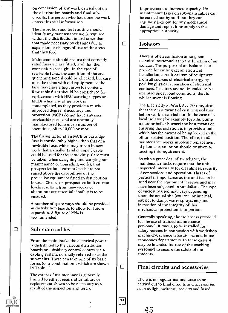
on conclusion of any work carried out onthe distribution boards and final sub-circuits, the person who has done the workenters this vital information.
The inspection and test routine shouldidentify any maintenance work requiredwithin the distribution board other thanthat made necessary by changes due toexpansion or changes of use of the areasthat they feed.
Maintenance should ensure that correctlyrated fuses etc are fitted, and that theirconnections are tight. In the case ofrewirable fuses, the condition of the arc-quenching tape should be checked, but caremust be taken with old equipment as thetape may have a high asbestos content.Rewirable fuses should be considered forreplacement with HRC cartridge types orMCBs when any other work iscontemplated, as they provide a much-improved degree of accuracy andprotection. MCBs do not have any userserviceable parts and are normallymanufactured for a given number ofoperations, often 10,000 or more.
The fusing factor of an MCB or cartridgefuse is considerably higher than that of arewirable fuse, which may mean in newwork that a smaller (and cheaper) cablecould be used for the same duty. Care mustbe taken, when designing and carrying outmaintenance or upgrading works, thatprospective fault current levels are notraised above the capabilities of theprotective equipment fitted in distributionboards. Checks on prospective fault currentlevels resulting from new works oralterations are essential if safety is to beensured.
A number of spare ways should be providedin distribution boards to allow for futureexpansion. A figure of 25% isrecommended.
Sub-main cables
From the main intake the electrical poweris distributed to the various distributionboards or subsidiary control centres via acabling system, normally referred to as thesub-mains. These can take one of six basicforms (or a combination), which are shownin Table 11.
The extent of maintenance is generallylimited to either repairs after failure orreplacement shown to be necessary as aresult of the inspection and test, or
improvement to increase capacity. Nomaintenance tasks on sub-main cables canbe carried out by staff but they canregularly look out for any mechanicaldamage and report it promptly to theappropriate authority.
111 I Isolators
There is often confusion among non-technical personnel as to the function of anisolator. The purpose of an isolator is toprovide for cutting off an electricalinstallation, circuit or item of equipmentfrom all sources of electrical energy bypositive physical separation of electricalcontacts. Isolators are not intended to beoperated under load conditions, that iswhile current is flowing.
The Electricity at Work Act 1989 requiresthat there is a means of ensuring isolationbefore work is carried out. In the case of alocal isolator (for example for kiln, pumpmotor or boiler burner) the best means ofensuring this isolation is to provide a unitwhich has the means of being locked in theoff or isolated position. Therefore, in allmaintenance works involving replacementof plant, etc, attention should be given tomeeting this requirement.
As with a great deal of switchgear, themaintenance tasks require that the unit isinspected internally for cleanliness, securityof connections and operation. This is ofparticular importance as the unit has to besited near the equipment it serves and mayhave been subjected to vandalism. The typeof enclosure used may vary dependingupon the actual site (external or internal,subject to damp, water sprays, etc) andinspection of the integrity of thismechanical protection is important.
Generally speaking, the isolator is providedfor the use of trained maintenancepersonnel. It may also be installed forsafety reasons in connection with workshopmachinery, science laboratories and homeeconomics departments. In these cases itmay be intended for use of the teachingpersonnel to ensure the safety of thestudents.
Final circuits and accessories
There is no regular maintenance to becarried out to final circuits and accessoriessuch as light switches, sockets and fused
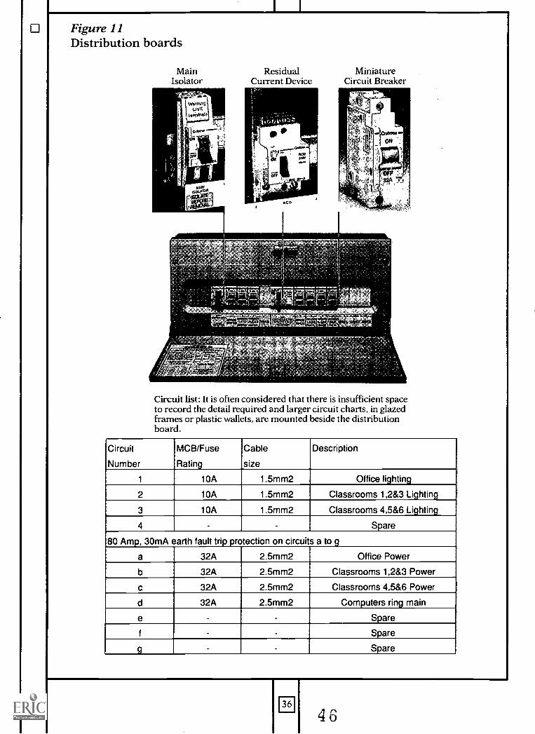
Figure 11Distribution boards
MainIsolator
ResidualCurrent Device
-
MiniatureCircuit Breaker
Circuit list: It is often considered that there is insufficient spaceto record the detail required and larger circuit charts, in glazedframes or plastic wallets, are mounted beside the distributionboard.
Circuit
Number
MCB/Fuse
Rating
Cable
size
Description
1 10A 1.5mm2 Office lighting
2 10A 1.5mm2 Classrooms 1,283 Lighting
3 10A 1.5mm2 Classrooms 4,5&6 Lighting
4 - Spare
80 Amp, 30mA earth fault trip protection on circuits a to g
a 32A 2.5mm2 Office Power
b 32A 2.5mm2 Classrooms 1,283 Power
c 32A 2.5mm2 Classrooms 4,5 &6 Power
d 32A 2.5mm2 Computers ring main
e Spare
f Spare
9 Spare
36
4u

outlets other than the inspection and testroutines.
Users should be vigilant over observablefaults or damage, and they should ensurethese are attended to by a competentperson very quickly. This is of particularimportance with regard to accessories inthat this is the one point in the electricalsystem where the consumer comes intointentional close contact with electricityand has control over the release of energy.Because these accessories are visible andaccessible they may often be subjected toabdse, in particular to the shuttermechanism that is intended to preventobjects other than an appropriate plugfrom being inserted in the socket outlet.
Replacement /improvement
When planning major rewiring works,consideration should be given to:
a. co-ordination with other maintenanceworks such as cleaning, repairs to fabricand decorations.b. likely disruption to the premisesoperation during the work.c. disturbance of materials that mightcreate a hazard, such as asbestos.d. future teaching needs.e. the existence of a suitabletrunking/conduit system.f. cost-benefit of in-built spare capacityand flexibility.
Proprietary systems for distributing powerto socket outlets are available but they arenot recommended for general use, whereplugs and socket outlets complying with BS1363: 198417 should be used internally andwith BS 4343: 196818 for external positions.
Consideration should be given to theinstallation of RCDs, although care isneeded. Equipment in general, and forinformation technology, control, etc inparticular, increasingly containssemiconductor devices which can result inthe normal ac sinusoidal waveform beingmodified, for example rectified or chopped.These modified waveforms are said tocontain a pulsating dc component.Consequently, in the event of an earth faulton the equipment it is probable that theearth fault current waveform will contain apulsating dc component. Not all RCDs willrespond to such a fault current and maythus not provide the intended degree ofprotection; however, there are many
devices which will respond to fault currentswith pulsating dc components and thuscare is needed in selection. All externalsocket outlets - those which will supplyequipment used outdoors and those inplant areas - should be protected by anRCD.
The design of final circuits supplyingcomputers and data-processing equipmentwhere the total earth leakage current innormal service exceeds 10mA is covered inSection 607 (`Earthing requirements for theinstallation of equipment having high earthleakage currents') of the IEE WiringRegulations" , which gives particularrequirements relating to the earth leakagecurrents of such equipment.
Although flush (buried) services may give abetter appearance, surface installations canbe more economic and necessitate little orno building or redecoration works. Inaddition, surface mounting allowsmodifications or extensions to be moreeasily carried out. With careful design andinstallation, cable routes can be selected tofacilitate future tapping-in to provideadditional points.
For a primary school, it is recommendedthat one double switched socket outlet withneon indicator should be fitted to each wallof a conventional classroom, at a heightwhere they would be visible by the teacher(1m above floor level). The precise siting ofeach socket outlet should be agreed withthe school staff, within specifiedconstraints. This work can be incorporatedwhen any other electrical work is found tobe necessary. Advice should be sought fromstaff as to the priorities for the differentareas.
For a new secondary school, typicalnumbers of socket outlets are shown inTable 12; these may require localmodification for various areas. Existingschools will generally have fewer socketoutlets but the table can be used as a guidewhen rewiring or upgrading. As withprimary schools, discussions should be heldwith school staff to set priorities.
If there is a fixed teacher position withinthe classroom it will be useful to provide anadditional twin socket outlet beside it.
47
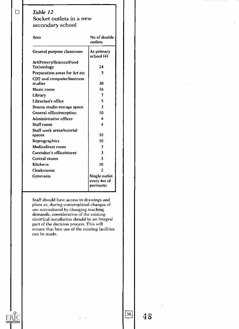
Table 12Socket outlets in a newsecondary school
Area No of doubleoutlets
General purpose classroom
Art/Pottery/Science/FoodTechnologyPreparation areas for Art etcCDT and computer/businessstudiesMusic roomLibraryLibrarian's officeDrama studio storage spaceGeneral office/receptionAdministrative officesStaff roomStaff work areas/tutorialspacesReprographicsMedical/rest roomCaretaker's office/storesCentral storesKitchensCloakroomsGymnasia
As primaryschool (4)
24
5
30
16
7
5
3
10
4
4
10
10
3
3
3
10
2
Single outletevery 4m ofperimeter
Staff should have access to drawings andplans as, during contemplated changes ofuse necessitated by changing teachingdemands, consideration of the existingelectrical installation should be an integralpart of the decision process. This willensure that best use of the existing facilitiescan be made.
38 48
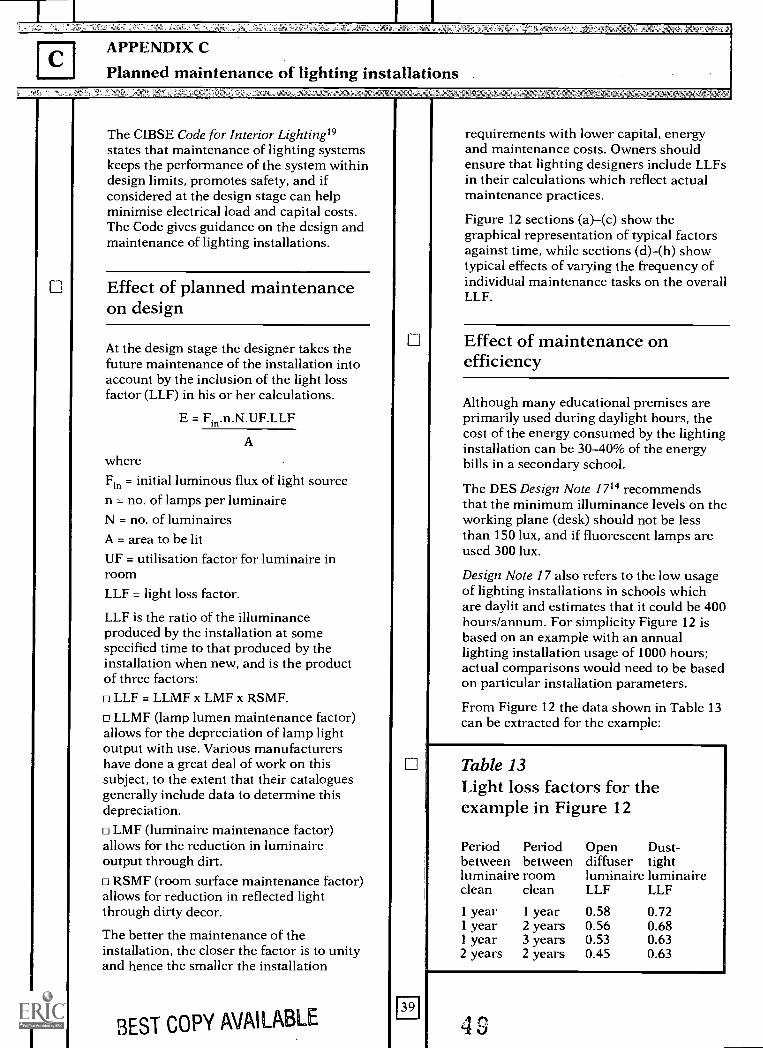
APPENDIX C
Planned maintenance of lighting installations
The CIBSE Code for Interior Lighting19states that maintenance of lighting systemskeeps the performance of the system withindesign limits, promotes safety, and ifconsidered at the design stage can helpminimise electrical load and capital costs.The Code gives guidance on the design andmaintenance of lighting installations.
Effect of planned maintenanceon design
At the design stage the designer takes thefuture maintenance of the installation intoaccount by the inclusion of the light lossfactor (LLF) in his or her calculations.
E = Fin.n.N.UF.LLF
A
whereFin = initial luminous flux of light sourcen = no. of lamps per luminaireN = no. of luminairesA = area to be litOF = utilisation factor for luminaire inroomLLF = light loss factor.
LLF is the ratio of the illuminanceproduced by the installation at somespecified time to that produced by theinstallation when new, and is the productof three factors:o LLF = LLMF x LMF x RSMF.
LLMF (lamp lumen maintenance factor)allows for the depreciation of lamp lightoutput with use. Various manufacturershave done a great deal of work on thissubject, to the extent that their cataloguesgenerally include data to determine thisdepreciation.
LMF (luminaire maintenance factor)allows for the reduction in luminaireoutput through dirt.
RSMF (room surface maintenance factor)allows for reduction in reflected lightthrough dirty decor.
The better the maintenance of theinstallation, the closer the factor is to unityand hence the smaller the installation
BEST COPY AVAILABLE39
requirements with lower capital, energyand maintenance costs. Owners shouldensure that lighting designers include LLFsin their calculations which reflect actualmaintenance practices.
Figure 12 sections (a)-(c) show thegraphical representation of typical factorsagainst time, while sections (d)-(h) showtypical effects of varying the frequency ofindividual maintenance tasks on the overallLLF.
Effect of maintenance onefficiency
Although many educational premises areprimarily used during daylight hours, thecost of the energy consumed by the lightinginstallation can be 30-40% of the energybills in a secondary school.
The DES Design Note 1714 recommendsthat the minimum illuminance levels on theworking plane (desk) should not be lessthan 150 lux, and if fluorescent lamps areused 300 lux.
Design Note 17 also refers to the low usageof lighting installations in schools whichare daylit and estimates that it could be 400hours/annum. For simplicity Figure 12 isbased on an example with an annuallighting installation usage of 1000 hours;actual comparisons would need to be basedon particular installation parameters.
From Figure 12 the data shown in Table 13can be extracted for the example:
Table 13Light loss factors for theexample in Figure 12
Period Periodbetween betweenluminaire room
Open Dust-diffuser tightluminaire luminaire
clean clean LLF LLF
1 year 1 year 0.58 0.721 year 2 years 0.56 0.681 year 3 years 0.53 0.632 years 2 years 0.45 0.63
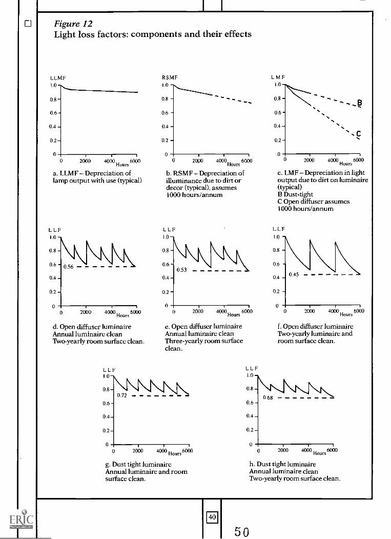
Figure 12Light loss factors: components and their effects
LLMF RSMF
1.0 1.0
0.8 - 0.8 -
0.6 - 0.6 -
0.4 - 0.4 -
0.2 - 0.2 -
0 00 2000 4000 6000
Hours
a. LLMF Depreciation oflamp output with use (typical)
LLF
0
I
2000 4"Hours
6000
d. Open diffuser luminaireAnnual luminaire cleanTwo-yearly room surface clean.
0 2000 4000 6000Hours
b. RSMF Depreciation ofilluminance due to dirt ordecor (typical), assumes1000 hours/annum
2000 4000Hours
6000
c. LMF Depreciation in lightoutput due to dirt on luminaire(typical)B Dust-tightC Open diffuser assumes1000 hours/annum
LLF1.0 --
0.8 -
L L F
1.0
0.8 -
0.6 - 0.6 -0.53
0.4 - 0.4 - 0.45
0.2 - 0.2 -
0 00 2000 64" 6000
Hours
e. Open diffuser luminaireAnnual luminaire cleanThree-yearly room surfaceclean.
g. Dust tight luminaireAnnual luminaire and roomsurface clean.
LLF1.0
0.8 -
0.6 -
0.4 -
0.2 -
0
0.68
0 2000 4" 6000"f. Open diffuser luminaireTwo-yearly luminaire androom surface clean.
ti
0 2000 4" Hours 6000
h. Dust tight luminaireAnnual luminaire cleanTwo-yearly room surface clean.
40
50
From the data it can be deduced that forthe example:
increasing frequency of luminairecleaning from every two years to annuallyimproves efficiency by approximately 20%
increasing frequency of room surfacecleaning from every three years to annuallyimproves efficiency by approximately 5%E changing from open diffuser to dust-tightluminaires (with same utilisation factor)improves efficiency by approximately 18%
changing from open diffuser to dust-tightluminaires and increasing maintenancefrom every two years to annual clean ofluminaires and room surfaces improvesefficiency by approximately 37%.
Effect of better qualityequipment and maintenance onlife-cycle costs
If economic luminaire life is 20 years andusage is 400 hours/annum, on the basis offluorescent lamp life of over 6000 hours thelamp would have to be replaced only onceduring the life of a luminaire.
Consequently, for new and replacementinstallations it will be worth consideringthe life-cycle economics of using higherquality luminaires and lamps to takeadvantage of:
The more efficient polyphosphor krypton-filled fluorescent lamps. These produceapproximately 10% more light than theconventional argon-filled halophosphatelamp and use approximately 8% lessenergy. They are, however, more expensiveand can be used only in some switch andelectronic start luminaires.
The possibilities for reduction inmaintenance costs. In consideration of thelength of time between lamp replacements,when diffusers would have anyway to beremoved, it may be economic to use dust-sealed luminaires. These reduce luminairecleaning to wiping the external surfaces,which can be done by the caretaker. Thiswill be far less time-consuming, and hencecheaper, than removing an open diffuser,taking it down, washing it internally andexternally and replacing it.
Compact fluorescent lamps in preferenceto tungsten lamps.
Figure 13 sets out an example life-cyclecosting for a sample installation whichshows that, in this case, a life-cycle costsaving of 30% can be achieved through the
41
use of better luminaires with bettermaintenance.
It is impossible to generalise as eachinstallation has its own set of operating andmaintenance parameters which will need tobe considered; accurate life-cycle costing isessential.
Maintenance
Thus maintenance of lighting systems fallsinto three distinct types of work:1. Breakdown maintenance for thereplacement of failed lamps or luminaires.2. Planned preventive maintenance forcleaning and for the bulk relamping ofinstallations that have reached the end oftheir useful lives, before failures causeproblems.3. Planned maintenance for thereplacement of fittings that the inspectionand tests have shown to be necessary.
(The planned maintenance of the electricalaspects of the lighting installation is dealtwith in Appendix B.)
Where school staff carry out the cleaning ofluminaires and replacement of lamps, itmay be sensible to generate a rollingprogramme.
Care is needed when disposing of lamps.LOW-PRESSURE SODIUM (SOX, SLI, SOI)LAMPS MUST BE TREATED WITH EXTREME
CAUTION AS THE SODIUM THEY CONTAIN BURSTS
INTO FLAMES ON CONTACT WITH WATER.
When breaking up lamps for disposal,protective clothing, including goggles andgloves, must be worn, and precautionstaken against flying glass, etc (including there-use of replacement lamp wrappers tocontain flying pieces). This should be doneout-of-doors or in a well ventilated area.
Tungsten, fluorescent and discharge (otherthan SOX) lamps should be broken in acontainer and disposed of as glass waste.There is no need to break the tough innerarc tube of mercury and high-pressuresodium lamps.
Low-pressure sodium lamps should beplaced in a dry metal container up to aquarter full (not more than 20 lamps) andbe broken into small pieces. The containershould immediately be half filled withwater from a hose, the operator standing ata safe distance. After a few minutes theliquid should be decanted as foul waste andthe remainder disposed of as glass waste.
51
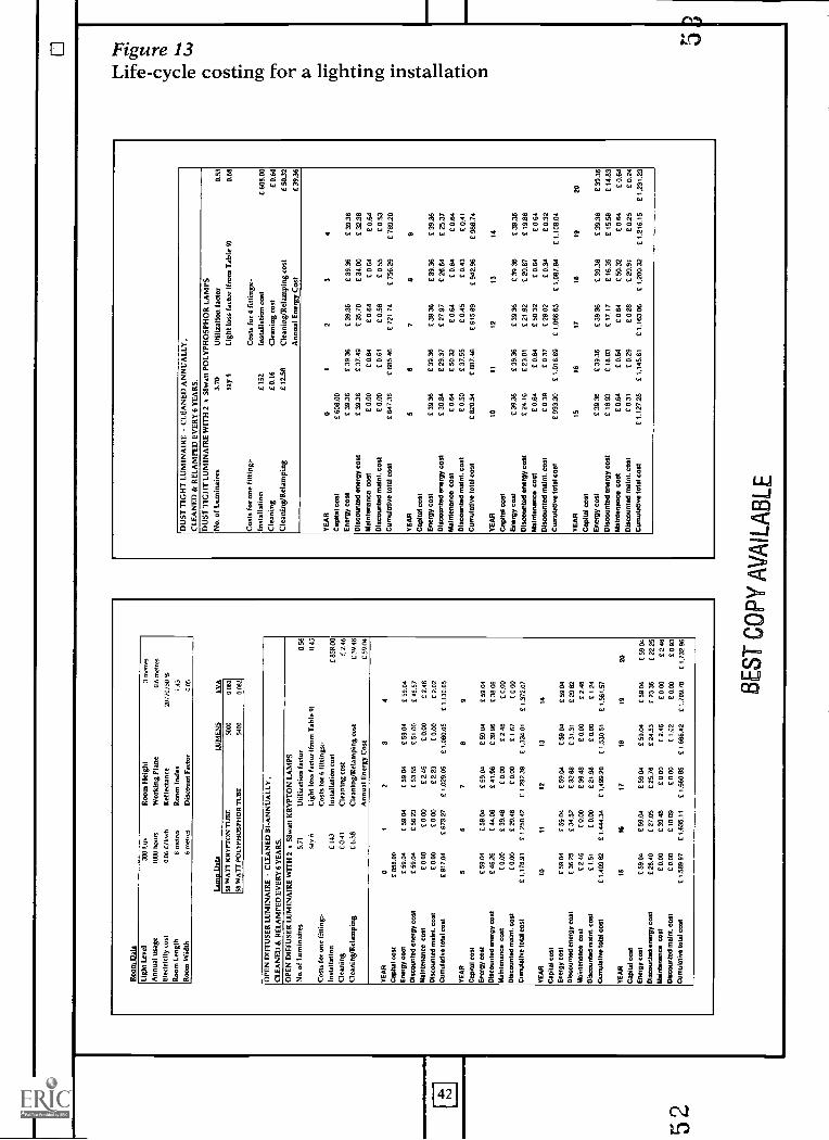
Roa
m D
ata
Ligh
t Lev
el30
0 Lu
xR
oom
Hei
ght
3 m
etre
s
Ann
ual u
sage
IMO
hou
rsW
orki
ng P
lane
0.6
met
res
Ele
ctric
ity c
ost
0.06
E/k
wh
Ref
lect
ance
20/7
0/50
%
Roo
m L
engt
h8
met
res
Roo
m In
dex
1.43
Roa
ns W
idth
6 m
etre
sD
isco
unt F
acto
r0.
05
Lam
p D
ate
LUM
EN
SkY
AS
s W
AIT
KR
YP
TO
N T
UB
E50
0000
82
58 W
AT
T P
OLY
PH
OS
PH
OR
TU
BE
5400
0 08
2
OP
EN
DIF
FU
SE
R L
UM
INA
IRE
- C
LEA
NE
D B
I- A
NN
UA
LLY
,C
LEA
NE
D &
RE
LAM
PE
D E
VE
RY
6 Y
EA
RS
.
OP
EN
DIF
FU
SE
R L
UM
INA
IRE
WIT
H 2
x 5
8wal
l KR
YP
TO
N L
AM
PS
No.
of L
umin
aire
s5.
71U
tiliz
atio
n fa
ctor
0.56
say
6Li
ght l
oss
fact
or (
from
Tab
le 9
10.
45C
osts
for
one
fittin
g-C
osts
for
6 fit
tings
:-In
stal
latio
n£
143
Inst
alla
tion
cost
C85
8.00
Cle
anin
g£0
.41
Cle
anin
g co
st£
2.46
Cle
anin
g/R
elam
ping
£6.5
8C
lean
ing/
Rel
ampi
ng c
ost
E39
.48
Ann
ual E
nerg
y C
ost
£ 59
.04
YE
AR
01
32
4
Cap
ital c
ost
E 8
58.0
0
Ene
rgy
cost
£ 59
.04
C 5
904
C 5
9.04
£ 59
.04
£ 59
.04
Dis
coun
ted
ener
gy c
ost
£ 59
.04
C 5
6.23
C 5
355
£ 51
.00
£ 48
.57
Mai
nten
ance
cos
t£
800
£ 0.
00C
2.4
6£
0.00
£ 2.
46D
isco
unte
d m
eant
. cos
t£
0.00
£ 0.
00E
2.2
3C
0.0
0£
2.02
Cum
ulat
ive
tota
l cos
tC
917
.04
C 9
73.2
7£
1.02
9.05
£ 1.
080.
05£
1,13
0.65
YE
AR
56
78
9
Cap
ital c
ost
Ene
rgy
cost
C 5
9.04
£ 59
.04
£ 59
.04
C 5
9.04
£ 59
.04
Dis
coun
ted
ener
gy c
ost
£ 46
.26
E 4
4.06
£ 41
.96
C 3
9.96
C 3
8.06
Mai
nten
ance
cos
tC
0.0
0£
39.4
8C
ow
E 2
.46
£ 0.
00D
isco
unte
d m
ain.
cos
t£
0.00
C 2
9.46
C c
oo£
1.67
£ 0.
00C
umul
ativ
e to
tal c
ost
£ 1,
1789
1£
1.25
0.42
£ 1,
292.
38£
1,33
4.01
£ 1.
372.
07
YE
AR
1011
1213
14
Cap
ital c
ost
Ene
rgy
cost
£ 59
.04
£ 59
.04
£ 59
.04
£ 59
84£
5984
Dis
coun
ted
ener
gy c
ost
E 3
6.25
£ 34
.52
£ 32
.88
E 3
1.31
£ 29
.82
Mai
nten
ance
cos
t£
2.46
£ 0.
00£
39.4
8£
0.00
£ 2.
46D
isco
unte
d in
tent
. cos
tC
1.5
1C
0.0
0£
21.9
8£
0.00
£ 1.
24
Cum
ulat
ive
tota
l cos
tf 1
.409
.82
£ 1.
444.
34£
1.49
9.20
£ 1.
530.
51£
1.56
1.57
YE
AR
1516
1718
1920
Cap
ital c
ost
Ene
rgy
cost
£ 59
.04
£ 59
.04
£ 59
.04
C 5
9.04
£ 59
04£
59.0
4D
isco
unte
d en
ergy
cos
t£
28.4
0£
27.0
5C
25.
76C
24.
53E
23.
36C
22.
25M
aint
enan
ce c
ost
C 0
.00
£ 39
.48
£ 0.
00£
2.46
£ 0.
00£
2.46
Dis
coun
ted
mai
nt. c
ost
£ 0.
00£
1809
C 0
.00
£ 1.
02£
aao
£ 0.
93C
umul
ativ
e to
tal c
ost
£ 1.
589.
97£
1.63
5.11
£ 18
6086
£ 1,
686.
42C
1,7
09.7
8£
1.73
2.96
DU
ST
TIG
HT
LU
MIN
AIR
E -
CLE
AN
ED
AN
NU
ALL
Y,
CLE
AN
ED
& R
ELA
MP
ED
EV
ER
Y 6
YE
AR
S.
DU
ST
TIG
HT
LU
MIN
AIR
E W
ITH
2 x
58w
att P
OLY
PH
OS
PH
OR
LA
MP
SN
o. o
f Lum
inai
res
3.70
Util
izat
ion
fact
or0.
53
say
4Li
ght l
oss
fact
or (
from
Tab
le 9
10.
68
Cos
ts fo
r on
e fit
ting,
-C
osts
for
4 f W
ings
:-In
stal
latio
nE
152
Inst
alla
tion
cost
E 6
08.0
0
Cle
anin
gE
0.1
6C
lean
ing
cost
E 0
.64
Cle
anin
g/R
elam
ping
E 1
2.58
Cle
anin
g/R
elam
ping
cos
t£
50.3
2
Ann
ual E
nerg
y C
ost
E 3
9.36
YE
AR
01
23
4
Cap
ital c
ost
E 6
08.0
0
Ene
rgy
cost
£ 39
.36
£ 39
.36
£ 39
.36
£ 39
.36
£ 39
.36
Dis
coun
ted
ener
gy c
ost
£ 39
.36
£ 37
.49
£ 35
.70
£ 34
80£
32.3
8M
aint
enan
ce c
ost
£ 0.
00£
0.64
£ 0.
64£
0.64
£ 0.
64
Dis
coun
ted
mai
nt. c
ost
E 0
.00
£ 0.
61£
0.58
£ 85
5£
0.53
Cum
ulat
ive
tota
l cos
t£
647.
36£
685.
46£
721.
74E
758
29£
789.
20
YE
AR
56
78
9C
apita
l cos
tE
nerg
y co
st£
39.3
6C
39.
36£
39.3
6£
39.3
6£
39.3
6
Dis
coun
ted
ener
gy c
oal
£ 30
.84
£ 29
.37
£ 27
.97
£ 26
.64
£ 25
.37
Mai
nten
ance
cos
tE
0.6
4C
50.
32E
0.6
4C
864
£ 0.
64D
isco
unte
d m
aint
. cos
t£
0.50
£ 37
.55
£ 0.
45£
0.43
£ 0.
41C
umul
ativ
e to
tal c
ost
C 8
20.5
4C
887
.46
£ 91
5.89
£ 94
2.96
C 9
68.7
4
YE
AR
1011
1213
14
Cap
ital c
ost
Ene
rgy
cost
£ 39
.36
C 3
9.36
C 3
9.36
£ 39
.36
C 3
9.36
Dis
coun
ted
ener
gy c
ost
C 2
4.16
£ 23
.01
£ 21
.92
£ 20
.87
£ 19
.88
Mai
nten
ance
cos
tC
0.6
4C
0.6
4C
50.
32£
0.64
£ 0.
64D
isco
unte
d m
aint
. cos
t£
0.39
£ 0.
37£
28.0
2C
0.3
4C
0.3
2
Cum
ulat
ive
tota
l cos
tC
993
.30
£ 1.
016.
69£
1.06
6.63
£ 1.
087.
84£
1.10
884
YE
AR
1516
1718
1920
Cap
ital c
ost
Ene
rgy
coal
£ 39
.36
£ 39
.36
£am
£ 39
.36
£ 39
.36
£ 39
.36
Dis
coun
ted
ener
gy c
ost
£ 18
.93
E 1
8.03
£ 17
.17
£ 16
.35
£ 15
.58
£ 14
.83
Mai
nten
ance
cos
t£
0.64
£ 0.
64£
0.64
£ 50
.32
C 0
.64
£ 0.
64D
isco
unte
d m
ain.
cos
t£
0.31
£ 0.
29£
0.28
£ 20
.91
£ 0.
25£
0.24
Cum
ulat
ive
tota
l cos
tC
1,1
27.2
8C
1.1
45.6
1£
1.16
3.06
£ 1,
200.
32£
1216
.15
£ 1,
231.
23
BE
ST C
OPY
AV
AIL
AB
LE
HAPPENDIX FA Planned maintenance of building services controls
Introduction
There are many published papers andarticles on the correct maintenance ofenvironmental controls. Many documentedcases show that incorrectly adjustedcontrols and settings cause considerableincrease in energy consumption rather thansaving this costly commodity. In manycases the energy management equipmenthas been installed incorrectly; for example,cases have been cited of compensators(which are designed to adjust thetemperature of the water flowing to theradiator system in accordance with changesin the outside temperature) where nooutside thermostat was installed. Anothercase was the same type of equipment wherethe outside thermostat was fitted to achimney, giving a completelyunrepresentative temperature. In both thesecases the installation was faulty and couldnever have been correctly commissioned;therefore, any anticipated energy savingshad never been achieved. In addition, nomaintenance was being carried out (or if itwas, not by a competent person) as correctmaintenance would have revealed thesetypes of fault.
Items in the category of building servicescontrols include the electronic buildingenergy management systems and controlsassociated with the use of energy inbuildings such as lighting control systems,compensator/optimisers, time switches,valves, dampers, sensing equipment likethermostats, motor control centres, starterboxes, boiler burner control units, isolators,contactors, electro-mechanical andelectronic relays, thermal overloads,microprocessors, timers, multiple camunits, indicator lamps, push buttons andmetal enclosures, many of which arecommon to main switchgear.
Environmental conditions can be controlledand energy savings realised only if they arefully and correctly used; they shouldtherefore be relatively easy to operate andmonitor. A great danger is that if they aretoo complicated to use, they will remain inthe overridden positions.
47
Designed environmental conditions andefficient energy use will not be sustainedunless controls are regularly maintained. Assensors age, wear with use, become soiled,etc they require cleaning and adjustment ifthey are to operate at design conditions.
Now that establishments have to fund fuelusage it is important that adequatemaintenance of controls is carried out toavoid unnecessary expenditure.
Maintenance
The maintenance of building servicescontrols is a specialist area of expertise,which in many instances will require bothelectrical and mechanical services skillssuch as exhaust gas analysis, measurementof air/water flow rates etc. Although it isacknowledged that the typical labour ratesfor a skilled controls technician are likely tobe 30-60% more than for a single tradecraftsman, the time taken by a skilled manfor fault location and rectification will oftenbe much less than using a generaltradesman, and a positive repaymentthrough correctly adjusted controls shouldbe achieved.
The cost of maintenance is not likely toexceed 1% of the total fuel bill. This wouldprovide for a single visit to check settings toensure that correct temperatures are beingreached and control equipment is operatingcorrectly (both controller and actuator),and to make minor adjustments. Morecomplex sites may warrant more frequentvisits. Work beyond the process of checkingand minor adjustment would be the subjectof an additional quotation. Suchprocedures would be cost-effective, in thatmoney spent on regular maintenance wouldhave an identifiable payback and lead tofuture savings, i.e. investment for increasedefficiency.
It has already been stated that sensors areoften incorrectly located at installation, orcircumstances have changed and renderedtheir location inappropriate. Consequentlyit is useful, as part of planned maintenance,to check conditions both externally andwithin the controlled environment, atlocations other than where sensors are
J8
located, to evaluate the suitability of sensorlocation.
The extent to which a non-electricallytrained person can carry out maintenanceon this type of equipment is limited tocleaning exteriors, visually inspecting theexterior of the equipment and cabling andtesting the function of the equipment. It isrecommended that for each site a checklistof normal running conditions is provided.It should detail what equipment andassociated indicators should be operating,and at what times, for the school personnelto check; it should also show the settings oftime switches (see following paragraph).The purpose of indicator lamps is to showthe operating condition and it is obviouslynecessary to ensure that bulbs are replacedas soon as they fail.
Much energy is wasted simply throughincorrect setting of controls, e.g. timeswitches. As a minimum, eachestablishment should have a list of allsettings of all time switches, etc andinstructions for the adjustment and settingof each type, specific to the site. Staffshould be able to carry out this adjustmentand setting. One of the problems with thistype of equipment is that it is generallyfitted with an override mechanism, whichis often activated and then left onindefinitely. The costly, energy-wastingconsequences of this type of action shouldbe brought to the attention of the staff andconsideration given to installation ofremote indicators to show when timeswitches are being overridden.
Replacement/improvement
Thought should be given to theintroduction or improvement of zoning toallow controls to respond to areas ofdiffering demand, aspect, etc and for theprovision of heating and lighting for partialoccupation of buildings, for example forextracurricular activities. There may be thepossibility of partial funding from theorganisation using the facilities. Meteringwould make possible direct charging forthese sorts of activity.
Only qualified people should determine theuse of compensator/optimisers, zoning andcontrols in general, otherwise unacceptableconditions can occur due to a bad orinappropriate controls strategy.
48 59
Where bulk relamping is contemplated,there are a number of specialist contractorswho offer a range of services includingcleaning of fittings, relamping, minorrepairs, supply of lamps and disposal ofexpended units.
In whatever way the work is carried out itshould be properly planned andprogrammed, with completed workrecorded. An 'as-installed' lightinginstallation drawing, with each luminairegiven a unique reference, should help.
Although there is a variety of areas where itmay be possible to employ uplightingdesigns, these are of limited use because ofthe potential for vandalism, particularlydebris being thrown up and entering thereflectors, dirtying them and possiblyproducing a fire hazard.
Precautions
PCB, a chemical which was previously usedin the manufacture of capacitors forfluorescent light fittings, has been found tobe highly carcinogenic. Fluorescent lightfitting capacitors manufactured in theUnited Kingdom after 1976 are unlikely tocontain PCB and are supposed to be date-coded. Government regulations publishedin 1986 banned the sale of PCB-filledcapacitors. This type of capacitor is nowgenerally of a different type of construction,that is dry. However, high-capacitydischarge lighting (floodlights) havecapacitors as part of the control gear, oftenfilled with a liquid, normally with avegetable oil base, not PCB.
The capacitors used in fluorescent lightingthat were manufactured prior to 1976should be considered as likely to containthis material. These capacitors may fail. Incertain modes of failure, the PCB may leakout. This material, when warm, has aconsistency of light oil and may flow intothe body of the luminaire or diffuser oreven leak onto the floor. Leakage may showas a brown stain. Should this occur, thelight fitting should be switched off and asuitably trained maintenance operativecalled to change the faulty capacitor. Allcontact of oil on the skin should beavoided. Guidance issued states that thefaulty capacitor, after removal with the useof gloves, should be wrapped in absorbentmaterial and placed in a plastic bag alongwith any cleaning materials used to cleanthe luminaire. The NICEIC guidance
43
further states that the bag may then bedisposed of as normal waste, unless localrequirements specify otherwise. It isrecommended that the guidance of thelocal authority Environmental HealthDepartment is sought on disposal,particularly when considering large-scalereplacement.
Special disposal machines are available,but these may not be an economic prospectfor a single establishment.
Lighting controls
Lighting control systems are discussedelsewhere; however, the staff should havesufficient information to be able toprogramme any user controls and, inparticular, to know how to adjust timesettings to account for holiday periods andchanges between Greenwich Mean Timeand British Summer Time. Unless theseinstructions are easy to understand and toimplement they will not be used, and anyprojected energy savings will never beachieved. Often the fitting of simple timeswitches can realise considerable savings.
A note of caution should be made whenconsidering automated switchingoperations. The life of a lamp is a functionof the running hours and the number ofswitching operations and other factors. Thegreater the frequency of switchingoperations, the shorter the life. At somepoint the amount of energy and costs savedmay in fact fall below the cost of replacinglamps at more frequent intervals; that is, ifthe lamp only lasts half as long, will theenergy saved by switching more oftenexceed the cost of replacing the lamp twice?No detailed work on this aspect of energycosts is known to Architects and BuildingBranch. Table 14 shows the relationshipbetween rated lamp life for fluorescentlamps on a three-hour switching cycle andother frequencies. A typical life would be7000 hours for a three-hour cycle.
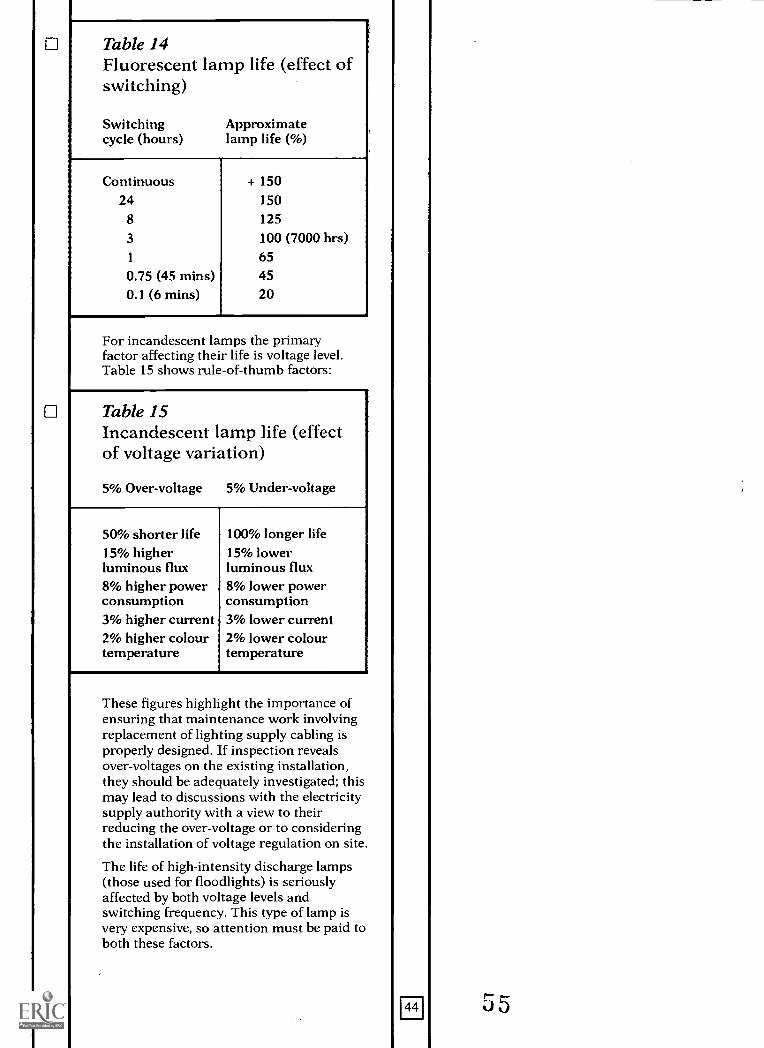
Table 14Fluorescent lamp life (effect ofswitching)
Switching Approximatecycle (hours) lamp life (%)
Continuous + 15024 150
8 125
3 100 (7000 hrs)1 650.75 (45 mins) 450.1 (6 mins) 20
For incandescent lamps the primaryfactor affecting their life is voltage level.Table 15 shows rule-of-thumb factors:
Table 15Incandescent lamp life (effectof voltage variation)
5% Over-voltage 5% Under-voltage
50% shorter life 100% longer life15% higher 15% lowerluminous flux luminous flux8% higher power 8% lower powerconsumption consumption3% higher current 3% lower current2% higher colour 2% lower colourtemperature temperature
These figures highlight the importance ofensuring that maintenance work involvingreplacement of lighting supply cabling isproperly designed. If inspection revealsover-voltages on the existing installation,they should be adequately investigated; thismay lead to discussions with the electricitysupply authority with a view to theirreducing the over-voltage or to consideringthe installation of voltage regulation on site.
The life of high-intensity discharge lamps(those used for floodlights) is seriouslyaffected by both voltage levels andswitching frequency. This type of lamp isvery expensive, so attention must be paid toboth these factors.
44
APPENDIX D
Planned maintenance of stage lighting
In areas used for drama performances(which may be public), much of the stagelighting relies upon plug, socket and leadarrangements and is often altered andrearranged by non-competent people(students, pupils and teaching staff). It ispotentially one of the greatest sources ofdanger of electric shock in an educationalpremises. The entire power system andstage lighting system should be protectedby RCDs.
The inspection and testing of theseinstallations need to be as thorough as thatof the remainder of the electricalinstallation and portable equipment, butneed to be carried out more frequently.
As with all electrical services, recordsshould be kept. A register should beprepared containing details of all items ofequipment such as controls, patch panels,prewired barrels, fittings, etc, with eachitem given, and preferably labelled with, aunique reference (asset code).
Arrangements should be made for trainingthe responsible person with overall controlof stage lighting equipment to carry outalterations to the lighting correctly andsafely and the training must be sufficient toenable him or her to correctly andobjectively assess when a competent personsuch as an electrician is required. Theresponsible person must ensure thatinspection and testing are carried out atappropriate times.
It is recommended that stage lightinginstallations comprising portable dimmers,plugs, sockets, flexible leads, etc areregarded as temporary installations and areinspected every three months, resultsrecorded and action taken to remedy anydefect. This includes stage lightingprovided specifically for an occasion,whoever arranges the provision.
It is recommended that the installationshould be inspected and tested after anychanges are made to wiring, connections,fixings/mountings/suspensions, etc andresults recorded.
All installations should be inspected andtested annually by a competent person, as
45
for the fixed electrical installation, and atest certificate issued.
One of the biggest potential hazards occurswhen ad hoc lighting suspensionarrangements are employed. Manyexamples of misuse of scaffoldingequipment have been observed, with littleregard to the correct electrical safety or tothe safety of the methods of suspension. Inmany cases electrical flexes have been usedto suspend equipment or have beenentwined around elements of the buildingstructure, thereby creating a potentialhazard.
FE1APPENDIX E
Planned maintenance of emergency lighting
Emergency lighting is provided to indicateclearly the escape routes, to illuminate theescape routes and the exits, and to ensurethat fire alarm call points and fire-fightingequipment can be readily located in theevent of electricity supply failure to thenormal lighting.
Emergency lighting therefore is essential tothe protection of life and must bemaintained to operate correctly. BS 5266:Part 1: 198820 deals with all aspects of theprovision of emergency lighting, detailingthe specific maintenance requirements andthe intervals at which they should becarried out.
To ensure the satisfactory operation andmaintenance of an emergency lightinginstallation a responsible person should beappointed to supervise the system andensure that:
records are keptprocedures are set out for the routine
inspection and testing of the installationthe system is maintained.
Records should be kept on site in which allpertinent information is entered, including:
date of completion certificate(s)(including those relating to alterations)
date and details of each inspection, test orservice and associated certificate
dates and details of defects and remedialactions
dates and details of any alterations.
It is recommended that these details bekept in a logbook. 'As-installed' drawingscould be marked to give each componentpart a unique reference (its asset code),which would be entered in the logbook andmarked on the component itself. Theroutine inspection and testing of theinstallation are carried out at two levels:
1. The first is that carried out by the user,without the aid of tools or equipment, suchas daily checks of indicating panels,monthly energising of each luminaire bysimulating supply failure, etc. The contentand intervals should be determined by acompetent person and set out in termswhich are understandable by a non-technical but responsible person.
46
2. Other regular maintenance work, suchas the three-yearly inspection and test forcompliance with BS 5266: Part 1: 1988, andissue of the periodic inspection and testcertificate, etc, should be carried out by acompetent person. A copy of this certificatemay be required by the enforcing licensingauthority who may specify how frequentlythe work should be carried out.
Emergency lighting installations also havethe same maintenance requirements asthose for normal lighting, e.g. cleaning oflamps, luminaires, etc, and the inspectionand testing of the electrical installations.
J7
I
APPENDIX G1-6-1 Planned maintenance of fire alarm systems
Fire alarm systems are concerned with theprotection of life and of property.
Building Bulletin 721 deals with the designof fire alarms and refers to relevant BritishStandards which also deal withmaintenance, in particular BS 5839: Part122. In addition to British Standards a greatdeal of guidance is available from trade andother organisations, including:
The Association of British Insurers
The Electrical Contractors' Association
The Fire Officers' Committee
The Loss Prevention Council.
Guidance should also be sought from thelocal Fire Brigade.
BS 5839: Part 1 should be carefullyconsidered before setting up the operationand maintenance of a system; it details theparticular tasks required to be carried outand specifies the intervals between them.
To ensure the satisfactory operation andmaintenance of fire alarm systems, aresponsible person should be appointedwho should supervise the system andensure that:
a. Procedures are set out for dealing withalarms, system faults, false alarms, routineinspection and testing, and maintenance.
b. Records are kept.
c. Users of the system are trained.
d. Operation of the system is not impaired.
e. The system is maintained.
Advice on procedures and training andother guidance is given in BS 5839: Part 1.These measures should be agreed with theappropriate fire authority. Constantvigilance is required to ensure that thesystem operation is not impaired, such as bythe obstruction of detectors, callpoints etc.
Records should be kept, on site, of allpertinent information regarding the system,including:
name and location of the responsibleperson for the system
details of the maintenance contractor
49
dates, times and causes of alarms,including reference of initiating callpoint/detector
dates, times, symptoms and locations ofall faults/defects
dates, times and description of allmaintenance works (routine and call-out)
dates, times, and details of periods ofsystem isolation or reduced operation
details of all alterations to the system.
These details may be kept in a logbook. BS5839: Part 1 gives a sample logbook page,which is reproduced in Figure 14. 'As-installed' drawings could be marked to giveeach component part a unique reference(its asset code) to which to refer in thelogbook; the component could be markedwith its reference.
Regular maintenance is carried out at twolevels: the first, by the user, without the aidof tools and equipment. This includesroutine inspection and testing of the systemto ensure satisfactory operation.
Other regular maintenance work must becarried out by a competent person,including the checking of batteries andindicator functions every three months, andthe correct operation of any automaticdetectors annually. On completion of theworks of each service visit, the visit shouldbe recorded in the logbook together withany defects, which should be reported tothe responsible person, and arrangementsmade to remedy them. A test certificateshould be given to the responsible person; amodel certificate is given in BS 5839: Part 1.
To satisfy the requirements for work to becarried out by competent persons, it isrecommended that a contract for regulartests and maintenance is taken with areputable fire alarm service company at thehandover of the installation. New systemswhich may have manufacturer-specificelectronic components or software may becapable of being adequately maintainedonly by the manufacturer (or his/her agents)and this is a factor for consideration whenspecifying new equipment.
These systems should also be subjected tothe same tests and inspections as the mainelectrical systems, and at the sameintervals, as dealt with under Appendix A.
60
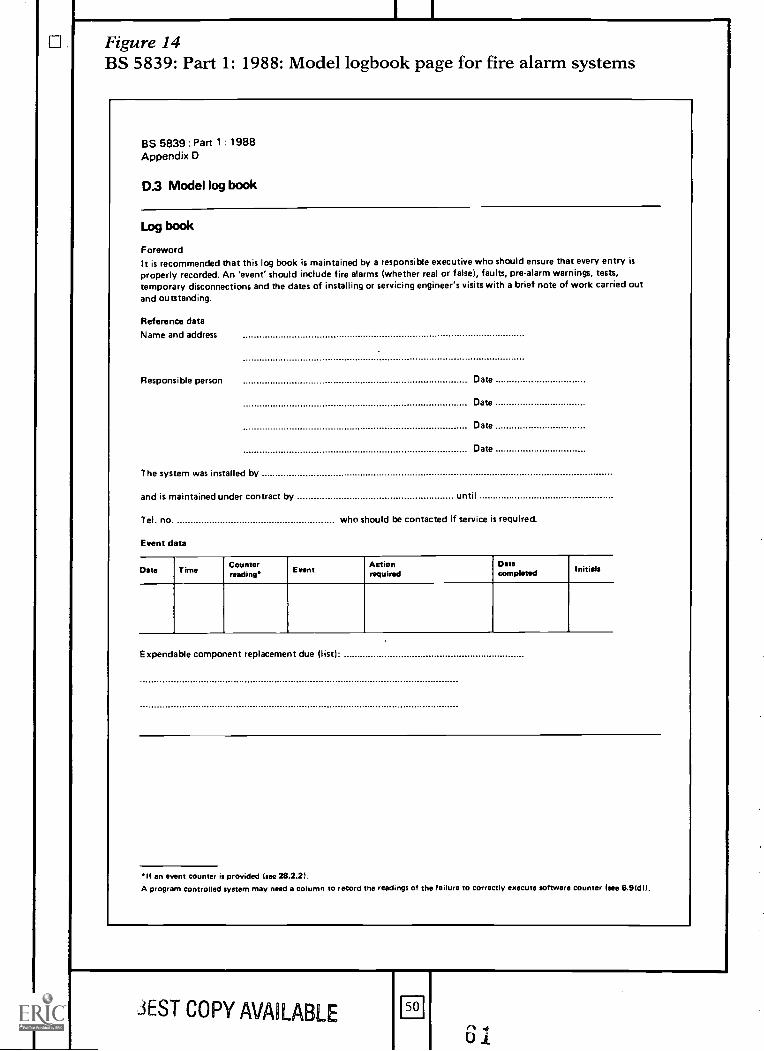
Figure 14BS 5839: Part 1: 1988: Model logbook page for fire alarm systems
BS 5839: Part 1 : 1988Appendix D
D.3 Model log book
Log book
ForewordIt is recommended that this log book is maintained by a responsible executive who should ensure that every entry isproperly recorded. An 'event' should include fire alarms (whether real or false, faults, pre-alarm warnings, tests,temporary disconnections and the dates of installing or servicing engineer's visits with a brief note of work carried outand outstanding.
Reference data
Name and address
Responsible person Date
Date
Date
Date
The system was installed by
and is maintained under contract by until
Tel. no. who should be contacted if service is required.
Event data
Date Time Counterreading*
EventActionrequired
Datacompleted Initials
Expendable component replacement due (list:
If an event counter is provided (see 28.2.21.A program controlled system may need a column to record the readings of the failure to correctly execute software counter (see 6.91d I).
JEST COPY AVAILABLE 50
U1
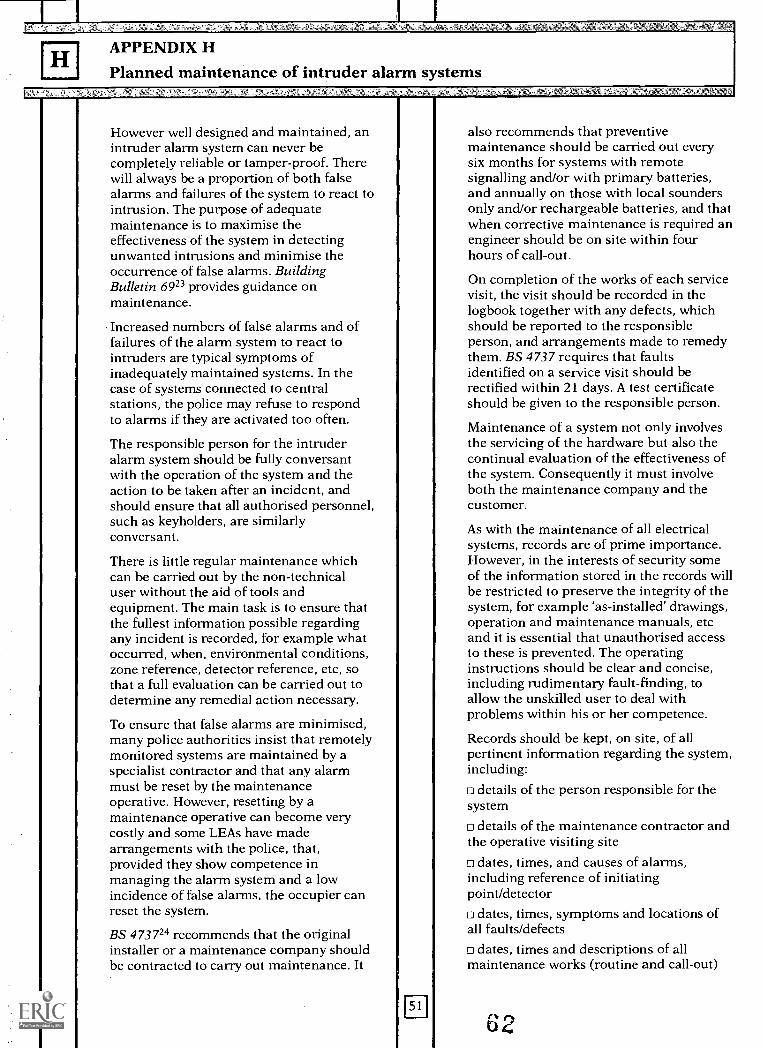
APPENDIX Htl Planned maintenance of intruder alarm systems
However well designed and maintained, anintruder alarm system can never becompletely reliable or tamper-proof. Therewill always be a proportion of both falsealarms and failures of the system to react tointrusion. The purpose of adequatemaintenance is to maximise theeffectiveness of the system in detectingunwanted intrusions and minimise theoccurrence of false alarms. BuildingBulletin 6923 provides guidance onmaintenance.
Increased numbers of false alarms and offailures of the alarm system to react tointruders are typical symptoms ofinadequately maintained systems. In thecase of systems connected to centralstations, the police may refuse to respondto alarms if they are activated too often.
The responsible person for the intruderalarm system should be fully conversantwith the operation of the system and theaction to be taken after an incident, andshould ensure that all authorised personnel,such as keyholders, are similarlyconversant.
There is little regular maintenance whichcan be carried out by the non-technicaluser without the aid of tools andequipment. The main task is to ensure thatthe fullest information possible regardingany incident is recorded, for example whatoccurred, when, environmental conditions,zone reference, detector reference, etc, sothat a full evaluation can be carried out todetermine any remedial action necessary.
To ensure that false alarms are minimised,many police authorities insist that remotelymonitored systems are maintained by aspecialist contractor and that any alarmmust be reset by the maintenanceoperative. However, resetting by amaintenance operative can become verycostly and some LEAs have madearrangements with the police, that,provided they show competence inmanaging the alarm system and a lowincidence of false alarms, the occupier canreset the system.
BS 473724 recommends that the originalinstaller or a maintenance company shouldbe contracted to carry out maintenance. It
also recommends that preventivemaintenance should be carried out everysix months for systems with remotesignalling and/or with primary batteries,and annually on those with local soundersonly and/or rechargeable batteries, and thatwhen corrective maintenance is required anengineer should be on site within fourhours of call-out.
On completion of the works of each servicevisit, the visit should be recorded in thelogbook together with any defects, whichshould be reported to the responsibleperson, and arrangements made to remedythem. BS 4737 requires that faultsidentified on a service visit should berectified within 21 days. A test certificateshould be given to the responsible person.
Maintenance of a system not only involvesthe servicing of the hardware but also thecontinual evaluation of the effectiveness ofthe system. Consequently it must involveboth the maintenance company and thecustomer.
As with the maintenance of all electricalsystems, records are of prime importance.However, in the interests of security someof the information stored in the records willbe restricted to preserve the integrity of thesystem, for example 'as-installed' drawings,operation and maintenance manuals, etcand it is essential that unauthorised accessto these is prevented. The operatinginstructions should be clear and concise,including rudimentary fault-finding, toallow the unskilled user to deal withproblems within his or her competence.
Records should be kept, on site, of allpertinent information regarding the system,including:o details of the person responsible for thesystem
details of the maintenance contractor andthe operative visiting siteo dates, times, and causes of alarms,including reference of initiatingpoint/detectoro dates, times, symptoms and locations ofall faults/defectso dates, times and descriptions of allmaintenance works (routine and call-out)
62
dates, times and details of periods ofsystem isolation or reduced operation
details of all alterations to the system.
These details may be kept in a logbook. 'As-installed' drawings could be marked to giveeach component part a unique reference(its asset code) to which to refer in thelogbook; the component could be markedwith its reference.
Plans for any work which extends buildingsmust take into account any requiredmodification of the intruder alarm system.To this end, and taking into considerationthe importance of these systems in avoidingcostly damage to property, a single point ofresponsibility is recommended to provideadequate co-ordination of work. Anotheraspect that needs to be considered is theuse of the premises outside normal hours,and whether zoning of the intruder alarmsystem could provide for protection ofunused parts of the buildings while otherparts are being used.
Es(1 00 J
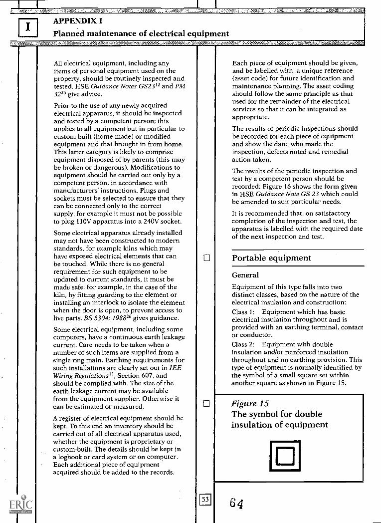
APPENDIX I
Planned maintenance of electrical equipment
All electrical equipment, including anyitems of personal equipment used on theproperty, should be routinely inspected andtested. HSE Guidance Notes GS2312 and PM3225 give advice.
Prior to the use of any newly acquiredelectrical apparatus, it should be inspectedand tested by a competent person; thisapplies to all equipment but in particular tocustom-built (home-made) or modifiedequipment and that brought in from home.This latter category is likely to compriseequipment disposed of by parents (this maybe broken or dangerous). Modifications toequipment should be carried out only by acompetent person, in accordance withmanufacturers' instructions. Plugs andsockets must be selected to ensure that theycan be connected only to the correctsupply, for example it must not be possibleto plug 110V apparatus into a 240V socket.
Some electrical apparatus already installedmay not have been constructed to modernstandards, for example kilns which mayhave exposed electrical elements that canbe touched. While there is no generalrequirement for such equipment to beupdated to current standards, it must bemade safe: for example, in the case of thekiln, by fitting guarding to the element orinstalling an interlock to isolate the elementwhen the door is open, to prevent access tolive parts. BS 5304: 198826 gives guidance.
Some electrical equipment, including somecomputers, have a continuous earth leakagecurrent. Care needs to be taken when anumber of such items are supplied from asingle ring main. Earthing requirements forsuch installations are clearly set out in IEEWiring Regulations", Section 607, andshould be complied with. The size of theearth leakage current may be availablefrom the equipment supplier. Otherwise itcan be estimated or measured.
A register of electrical equipment should bekept. To this end an inventory should becarried out of all electrical apparatus used,whether the equipment is proprietary orcustom-built. The details should be kept ina logbook or card system or on computer.Each additional piece of equipmentacquired should be added to the records.
Each piece of equipment should be given,and be labelled with, a unique reference(asset code) for future identification andmaintenance planning. The asset codingshould follow the same principle as thatused for the remainder of the electricalservices so that it can be integrated asappropriate.
The results of periodic inspections shouldbe recorded for each piece of equipmentand show the date, who made theinspection, defects noted and remedialaction taken.
The results of the periodic inspection andtest by a competent person should berecorded; Figure 16 shows the form givenin HSE Guidance Note GS 23 which couldbe amended to suit particular needs.
It is recommended that, on satisfactorycompletion of the inspection and test, theapparatus is labelled with the required dateof the next inspection and test.
Portable equipment
GeneralEquipment of this type falls into twodistinct classes, based on the nature of theelectrical insulation and construction:Class 1: Equipment which has basicelectrical insulation throughout and isprovided with an earthing terminal, contactor conductor.Class 2: Equipment with doubleinsulation and/or reinforced insulationthroughout and no earthing provision. Thistype of equipment is normally identified bythe symbol of a small square set withinanother square as shown in Figure 15.
Figure 15The symbol for doubleinsulation of equipment
64
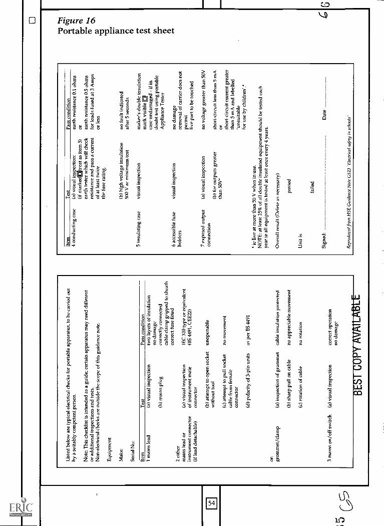
Lis
ted
belo
w a
re ty
pica
l ele
ctri
cal c
heck
s fo
r po
rtab
le a
ppar
atus
, to
be c
arri
ed o
utby
a s
uita
bly
com
pete
nt p
erso
n.
Not
e: T
his
chec
klis
t is
inte
nded
as
a gu
ide;
cer
tain
app
arat
us m
ay n
eed
diff
eren
tor
add
ition
al in
spec
tions
and
test
s.N
on-e
lect
rica
l che
cks
are
outs
ide
the
scop
e of
this
gui
danc
e no
te.
Equ
ipm
ent:
Mak
e:
Seri
al N
o:
Item
1 m
ains
lead
2 ei
ther
mai
ns le
ad o
rin
stru
men
t con
nect
or(i
f le
ad d
etac
habl
e)
or:
grom
met
/cla
mp
Tes
t(a
) vi
sual
insp
ectio
n
(b)
mai
ns p
lug
(a)
visu
al in
spec
tion
of in
stru
men
t mal
eco
nnec
tor
(b)
atte
mpt
to o
pen
sock
etw
ithou
t too
l
(c)
atte
mpt
to p
ull s
ocke
tca
ble
from
fem
ale
conn
ecto
r
Pass
con
ditio
ntw
o la
yers
of
insu
latio
nno
dam
age
corr
ectly
con
nect
edca
ble
clam
p gr
ippe
d to
she
ath
corr
ect f
use
fitte
d
IEC
320
type
or
equi
vale
nt(B
S 44
91, C
EE
22)
unop
enab
le
no m
ovem
ent
(d)
pola
rity
of
3-pi
n un
itsas
per
BS
4491
(a)
insp
ectio
n of
gro
mm
et
(b)
shar
p pu
ll on
cab
le
(c)
rota
tion
of c
able
3 m
ains
on/
off
switc
h(a
) vi
sual
insp
ectio
n
cabl
e in
sula
tion
prot
ecte
d
no a
ppre
ciab
le m
ovem
ent
no r
otat
ion
corr
ect o
pera
tion
no d
amag
e
BE
ST C
OPY
AV
AIL
AB
Item
4 co
nduc
ting
case
Tes
t(a
) vi
sual
ins
ectio
n:(i
f m
arke
diE
trea
t as
item
5)
eart
h te
ster
whi
ch w
ill c
heck
resi
stan
ce a
nd p
ass
a cu
rren
tof
at l
east
twic
eth
e fu
se r
atin
g.
(b)
high
vol
tage
insu
latio
n50
0 V
ac
min
imum
test
5 in
sula
ting
case
visu
al in
spec
tion
6 ac
cess
ible
fus
evi
sual
insp
ectio
nho
lder
s
7 ex
pose
d ou
tput
(a)
visu
al in
spec
tion
conn
ectio
n(b
) fo
r ou
tput
s gr
eate
rth
an 5
0V
Pass
con
ditio
nea
rth
resi
stan
ce 0
.1 o
hms
or eart
h re
sist
ance
0.5
ohm
sfo
r lo
ads
fuse
d at
3 A
mps
or le
ss
no f
ault
indi
cate
daf
ter
5 se
cond
s
mak
er's
dou
ble
insu
latio
nm
ark
visi
ble
case
und
amag
ed -
if in
doub
t tes
t usi
ng p
orta
ble
App
lianc
e T
este
r
111
no d
amag
ere
mov
al o
f ca
rrie
r do
es n
otpe
rmit
live
part
to b
e to
uche
d
no v
olta
ge g
reat
er th
an 5
0V
shor
t-ci
rcui
t les
s th
an 5
mA
Or
shor
t-ci
rcui
t cur
rent
gre
ater
than
5 m
A a
nd la
belle
d'u
nsui
tabl
efo
r us
e by
chi
ldre
n'.*
" ie
live
at m
ore
than
50
V w
hen
in u
se.
NO
TE
: at l
east
25%
of
all d
oubl
e in
sula
ted
equi
pmen
t sho
uld
be te
sted
eac
hye
ar ie
all
equi
pmen
t is
test
ed a
t lea
st o
nce
ever
y 4
year
s.
Ove
rall
resu
lt (D
elet
e as
nec
essa
ry)
Uni
t is
pass
ed
faile
d
Sign
ed:
Dat
e
Rep
rodu
ced
from
HSE
Gui
danc
e N
ote
GS2
3 'E
lect
rica
l saf
ety
in s
choo
ls'
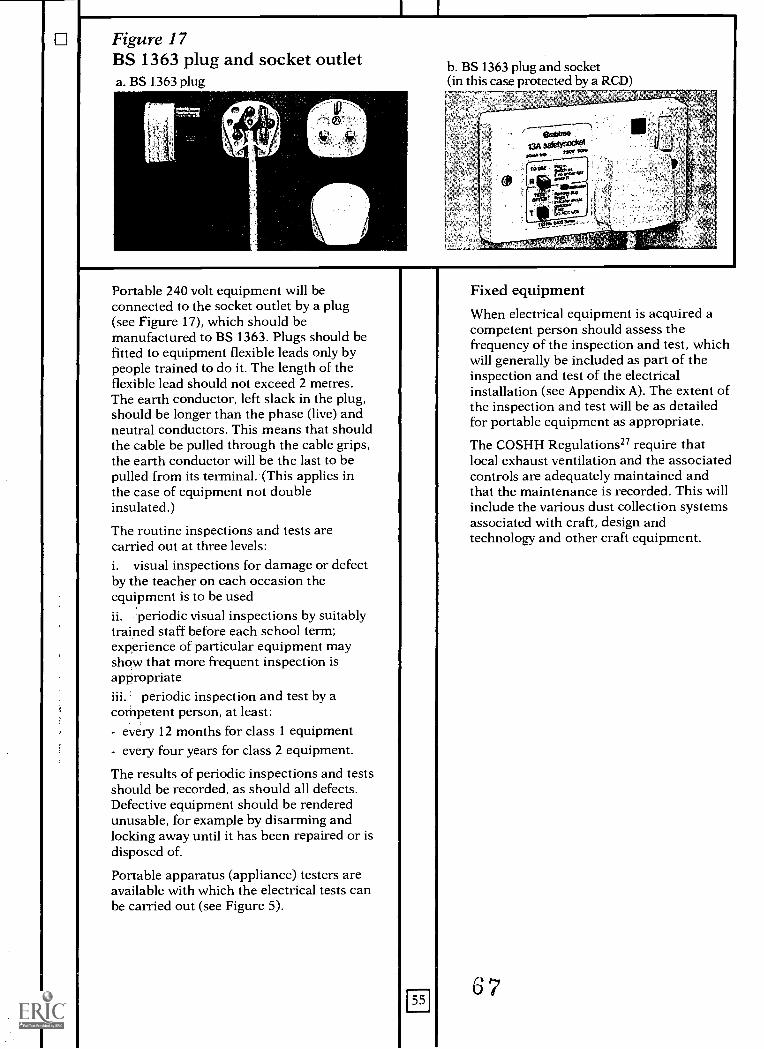
Figure 17BS 1363 plug and socket outleta. BS 1363 plug
b. BS 1363 plug and socket(in this case protected by a RCD)
Portable 240 volt equipment will beconnected to the socket outlet by a plug(see Figure 17), which should bemanufactured to BS 1363. Plugs should befitted to equipment flexible leads only bypeople trained to do it. The length of theflexible lead should not exceed 2 metres.The earth conductor, left slack in the plug,should be longer than the phase (live) andneutral conductors. This means that shouldthe cable be pulled through the cable grips,the earth conductor will be the last to bepulled from its terminal. (This applies inthe case of equipment not doubleinsulated.)
The routine inspections and tests arecarried out at three levels:i. visual inspections for damage or defectby the teacher on each occasion theequipment is to be usedii. 'periodic visual inspections by suitablytrained staff before each school term;experience of particular equipment mayshow that more frequent inspection isappropriateiii. periodic inspection and test by acompetent person, at least:- every 12 months for class 1 equipment- every four years for class 2 equipment.
The results of periodic inspections and testsshould be recorded, as should all defects.Defective equipment should be renderedunusable, for example by disarming andlocking away until it has been repaired or isdisposed of.
Portable apparatus (appliance) testers areavailable with which the electrical tests canbe carried out (see Figure 5).
Fixed equipmentWhen electrical equipment is acquired acompetent person should assess thefrequency of the inspection and test, whichwill generally be included as part of theinspection and test of the electricalinstallation (see Appendix A). The extent ofthe inspection and test will be as detailedfor portable equipment as appropriate.
The COSHH Regulations27 require thatlocal exhaust ventilation and the associatedcontrols are adequately maintained andthat the maintenance is recorded. This willinclude the various dust collection systemsassociated with craft, design andtechnology and other craft equipment.
67
FrlAPPENDIX JPlanned electrical maintenance of swimming pools
Swimming-pools in educationalestablishments vary enormously, betweenthose of indoor international competitionsize, open to members of the public, andvery small open-air pools built by voluntarybodies (such as PTAs). Notwithstandingthese differences in size (and indoor/outdoor locations), the requirements of theelectrical installations are exactly the same,and are covered by Section 602 of the IEEWiring Regulationsil: Swimming-pools'.
From investigations carried out for thepurposes of this Bulletin, it is apparent thatmany of the smaller installations built bypurely voluntary efforts fall below normallyaccepted standards; this situation must beremedied. If funds do not allow this tohappen immediately then the facilityconcerned should be taken out of use.
Inspection and testing should be carriedout to the same standards as other parts ofthe site electrical installation, but becauseof the increased hazard it should be done atmore frequent intervals.
In the case of swimming-pools ineducational establishments, the users areoften wet all over, without shoes or outerclothing, and the majority are of coursechildren, of much lighter body weight andtherefore more vulnerable to shock thanadults. Because of the decrease inresistance of the skin when it is wet,electric shocks are much more harmfulthan usual.
In addition to the increased hazardsassociated with electric shock, the methodsused to ensure the water conditions aresuitable for bathers often use chemicalsthat can be highly corrosive under certaincircumstances.
Where there is a need for electricalequipment near the pool it is essential thatthe enclosure is of the relevant protectionstandard. This is normally indicated by theIP number (Ingress Protection); these twodigits indicate respectively the degree ofmechanical protection and the degree ofprotection from liquids. For example, 1P55is the minimum standard enclosure to beused for electrical equipment which givesprotection against water-jets from anydirection.
56
It is necessary to be able to safely servicethe lighting installation in indoor pools,particularly fittings above it, and to takeaccount of the effects of condensation andacidic conditions that can occur. This is ofparticular importance with suspendedceilings.
With regard to the chemical treatmentand/or heating plant, again normalinstallation and maintenance practicesshould be employed, with particular regardto the possible adverse effects of chemicalspillage and the presence of water. Theseinstallations also require regular testing;the controls require good qualitymaintenance to ensure energy efficiencyand also that the chemical dosing of thewater is of acceptable accuracy. There are anumber of documented cases of chlorinepoisoning. Other chemicals employed inwater treatment can also be poisonous.
8
I I
APPENDIX K
Planned maintenance of lightning protection systems
The purpose of a lightning protectionsystem is to divert a lightning dischargeaway from the structure being protected tothe system itself, and then to convey thedischarge safely to earth via a low electricalresistance path.
The maintenance of these systems involvesperiodic inspection and testing, withappropriate remedial work then beingcarried out, to ensure the electricalintegrity of the installation and the securityof the fixings to the building structure andto eradicate the detrimental effects ofcorrosion.
If a lightning strike does occur, the valuesof current flowing through the protectionsystem could be very high; in the range of2,000-20,000A. This very high current canproduce considerable electromagneticforces, therefore the fixings must be verysecure. In addition to these forces producedby the passage of current, a considerabletemperature rise can take place whichproduces further mechanical forces.
Corrosion at any of the joints in the systemcan produce high-resistance joints, whichwould increase the heating effect, or in theworst case produce within the system sucha high resistance that the protection systemwould no longer function. This highlightsthe importance of constructing the systemfrom appropriate materials.
Subsequent maintenance, alteration,remedial works, etc should be inaccordance with BS 6651: 199028 whichstates that records should be kept anddetails their content.
Inspection and testing should be carriedout at least every 12 months. Weatherconditions and the season of the year mayaffect the soil condition, which in turnaffects the resistance to earth of the earthelectrodes. Therefore a shorter interval,perhaps 11 months, may be planned inorder to vary the seasons in which the testis carried out.
The visual inspection and testing should becarried out by a competent person toensure the installation complies with BS6651: 1985 and to assess the mechanical
condition. These observations should berecorded.
If the test results obtained are significantlyhigher than previous readings the causeshould be investigated and remedial actiontaken as necessary.
The installation and maintenance of thesesystems are normally carried out byspecialist contractors. As with many otheraspects of electrical maintenance, the onlystaff tasks are to observe and to report tothe appropriate authorities if damage hasoccurred. As lightning protection systemsare fixed to the external building structure,where the system comes near ground levelit can be vulnerable to vandalism orinadvertent damage by vehicles, etc.
If alterations or extensions are to be carriedout on a site (such as the erection of atelevision aerial or of new flues for heatingplant or new/extended buildings) anyexisting system should be extended orotherwise modified as necessary. If there isno protection system an assessment shouldbe carried out to determine if a system isrequired.
139
LAPPENDIX L
Planned maintenance of lifts
Lifts are one of the few items of buildingservices equipment for which there is aspecific legal requirement to carry outadequate maintenance, althoughmandatory only when either the FactoriesAct or the Offices, Shops and RailwayPremises Act applies to a premises.However, there is a requirement under theHealth and Safety at Work etc Act in otherpremises, and the guidance issued by theHSE does imply that the samerequirements should be adopted. There isalso a requirement to have the installationexamined by a competent person.
Lifts are complex electrical and mechanicaldevices which can be exposed to severevandalism. Consequently it is veryimportant to ensure that they areadequately maintained.
Because of the nature of these installations,it is normal practice to have themaintenance work carried out by aspecialist contractor, who is often one ofthe lift manufacturers, the vast majority ofwhom provide a variety of services.
HSE Guidance Note PM729 providesguidance.
Normal commercial practice is to have thethorough examinations carried out by anorganisation independent from themaintenance contractor. These specialistexaminations are normally carried out byan insurance company surveyor, whoseservices are provided by the variousinsurance companies that offer cover for alltypes of engineering plant. In addition tothe mandatory examinations of each liftinstallation at maximum intervals of sixmonths, a number of other specifiedaspects of examination and testing arenecessary, and although these may becarried out by a contractor, some wouldnormally be witnessed by the insurancecompany surveyor on behalf of the ownerof the installation.
It is the occupier's (or owner's)responsibility to ensure that the requiredexaminations and maintenance are carriedout. Contractual relationships between anoccupier (or owner) of a building and aspecialist insurance company for thethorough examinations, and a specialistcontractor for maintenance, to be carried
58
out as prescribed, do not absolve theoccupier (or owner) of the responsibility toensure the examinations are carried out ontime.
Legislation requires that records are kept;specifically it requires that a report of theexamination is issued within 28 days with aprescribed content and format. The occupier(or owner) of the building is required toretain these reports for a period of twoyears. Figure 19 shows a typical form.
Maintenance contracts offered by themanufacturers at the highest level ofservice provide for a planned preventivemaintenance programme of work, thereplacement of parts and a call-outresponse. Below this comprehensive servicethere are other contractual relationshipsavailable where time and/or materials arecharged for separately.
One factor that should be considered whenseeking competitive tenders is that if acontractor being considered is not themanufacturer then the contractor's abilityto obtain spare parts must be thoroughlyresearched. The same observation applies ifthe lift installation is fairly recent and partof the control system is software controlled.The software may be copyright protected orthe original supplier may not releaseinformation concerning the software.
Specific assistance and advice concerningcontractors and manufacturers can beobtained from the National Association ofLift Manufacturers.
There are a number of British Standardsthat apply to lifts with regard to design,installation, operation and maintenance,the main one being BS 56553°; thisstandard is in a number of componentparts. As with any standard it is importantto ensure the relevant part is being usedand that it is the most recent copy. Inaddition to the British Standards, theelectrical installation and maintenancework should be carried out in accordancewith the IEE Wiring Regulations".
70
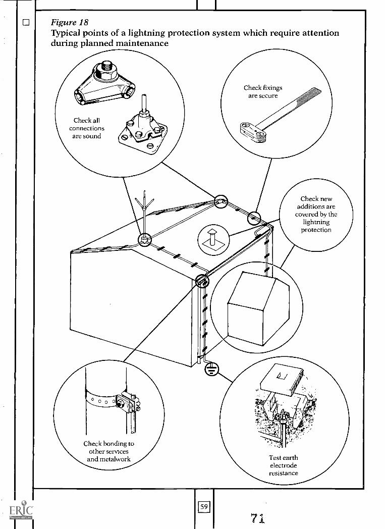
Figure 18Typical points of a lightning protection system which require attentionduring planned maintenance
Check fixingsare secure
Check allconnectionsare sound
Check newadditions are
covered by thelightning
protection
Check bonding toother services
and metalwork
59
71
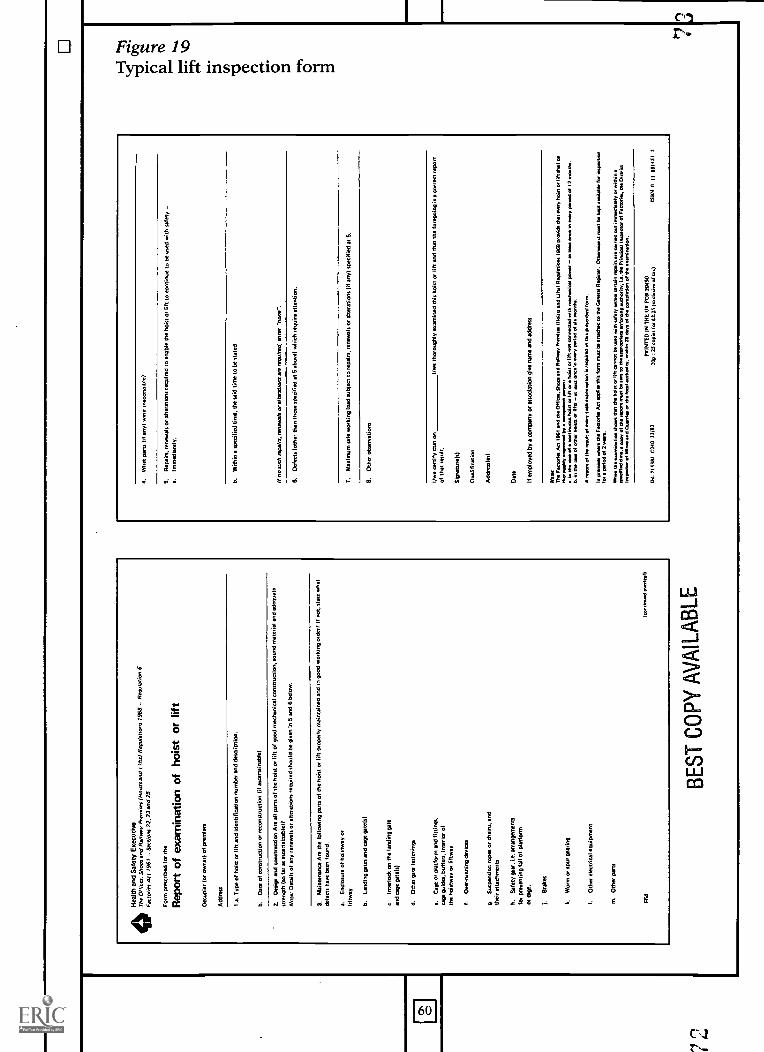
fRoi
sts
and
Lifts
) R
egul
atio
ns 1
968
- R
egu
brim
6H
The
al, o
thm
,a.,n
d. s
hSaf
ety.
,,ExR
eLu.
....ti
vve
Fac
torie
s A
ct 1
961
- S
ectio
ns 2
2,23
and
25
For
m p
resc
ribed
far
the
Rep
ort o
f exa
min
atio
n of
hoi
st o
r lif
t
Occ
upie
r (o
r ow
ner)
of p
rem
ises
Add
ress
1.a.
Typ
e of
hoi
st o
r lif
t and
iden
tific
atio
n nu
mbe
r an
d de
scrip
tion.
b.D
ate
of c
onst
ruct
ion
or r
econ
stru
ctio
n (if
asc
erta
inab
le)
2.D
esig
n an
d co
nstr
uctio
n A
re a
ll pa
rts
of th
e ho
ist o
r lif
t of g
ood
mec
hani
cal c
onst
ruct
ion,
sou
nd m
ater
ial a
nd a
dequ
ate
stre
ngth
(so
far
as a
scer
tain
able
)?N
ote:
Det
ails
of a
ny r
enew
als
or a
ltera
tions
req
uire
d sh
ould
be
give
n in
5 a
nd 6
bel
ow.
3.P
asin
tene
nce
Are
the
follo
win
g pa
rts
of th
e ho
ist o
r lif
t pro
pert
y m
aint
aine
d an
d in
goo
d w
orki
ng o
rder
? 11
not
, sta
te w
hat
defe
cts
haw
bee
n fo
und.
a.E
nclo
sure
of h
oist
way
or
liftw
ay
b.La
ndin
g ga
tes
and
age
gate
hl
e.In
terlo
ck o
n th
e la
ndin
g ga
tean
d ca
ge g
ate(
s1
d.O
ther
gat
e fa
sten
ings
e.C
age
or p
latfo
rm a
nd fi
tting
s,ca
ge g
uide
s, b
uffe
rs. i
nter
ior
ofth
e ho
istw
ay o
r lif
twaY
f.O
verr
unni
ng d
evic
es
g.S
uspe
nsio
n ro
pes
or c
hain
s. a
ndth
eir
rtta
dwne
nts
h.S
afet
y A
ar, i
.e. a
rran
gem
ents
foe
prev
entin
g fa
ll of
pla
tform
or a
ge.
j.B
rake
s
k.W
orm
or
spot
gea
ring
I.O
ther
dem
ists
l equ
ipm
ent
m. O
ther
par
ts
F54
kien
snue
l ow
neel
)
BE
ST C
OPY
AV
AIL
AB
LE
4.W
hat p
arts
(if
anyl
wer
e in
acce
ssib
le?
5.R
egai
n, r
enew
als
or a
ltera
tions
req
uire
d to
ena
ble
the
hois
t or
lift t
o co
ntin
ue to
be
used
with
saf
ety
-a.
Imm
edia
tely
.
b.W
ithin
41
spec
ified
tim
e, th
e sa
id ti
me
to b
e st
ated
If no
suc
h re
pairs
, ren
ewal
s or
alte
ratio
ns N
s m
ain:
5, e
nter
-no
ne-.
6.D
efec
ts (
othe
r th
an th
ose
spec
ified
at 5
abo
ve)
whi
ch r
equi
re a
ttent
ion.
7.M
axim
um s
afe
wor
king
load
sub
ject
to r
epai
rs. r
enew
als
or a
ltera
tion
lit e
nv)
spec
ified
at 5
.
8.O
ther
obs
erva
tions
I/we
cert
ify th
at o
nI /
we
thor
ough
ly e
xam
ined
Otis
hoi
st o
r lif
t and
that
the
fore
goin
g is
a b
arre
ns r
epor
tof
that
res
ult,
Sig
natu
r(s)
Qua
lific
atio
n
Add
ress
les)
Dat
e
If em
ploy
ed b
y a
rom
Pen
Y o
r as
soci
atio
n gi
ve fu
me
and
addr
ess
Nom
T. F
... A
n 19
81 a
nd th
e O
ffic,
Sam
and
Pea
vey
.... D
ioin
a an
d Li
fts)
Illea
dstio
ns to
m tu
ne. e
at e
ery
hoid
or
lift .
11 d
ede
ec.a
ttly
mon
d. b
y ow
e.. p
erse
rt:
in th
e ta
w e
dco
nthe
u. h
ole
or li
ft oe
hois
t et I
II t n
ot c
onne
cted
with
ned
unic
el m
ew -
or
bet o
r. in
er.
per
iod
of 1
2 m
onde
.O
. in
. or
of o
tnw
hol
m o
r lif
t. -
et 5
.r tw
in w
owy
peel
. of .
men
..
. rep
ort o
f Ow
res
ult o
f nar
y su
ch e
sam
inst
Ion
Is e
spui
rod
in th
is a
tone
. for
m.
In g
em. e
hesa
do
fect
orlw
Act
ad0
11os
tph
form
nes
t be
attc
hol t
o th
e G
sner
el R
epar
tee.
Oth
envi
a it
net t
o ke
pt e
vils
ble
for
insp
ectio
nIc
epe
riod&
2 y
en.
W. t
he...
estio
n th
an th
at th
e 11
d0 o
. lif
t can
not b
e le
ad w
ith W
ere
tndi
t ert
en n
omie
e er
a ca
rrie
d ou
t ine
rned
ien.
or
with
in.
smcA
lad
tin, c
op o
f Os
rape
r m
et b
e se
nt to
Ow
so.
.aw
enf
orci
ng o
utho
rity,
i.e.
the
Ptie
cigo
tl Iw
qrae
tea
of r
ecto
ries,
. D
ireic
tI..
. of M
. and
Ote
srey
(,/
.1.1
a ...
.,,,,
,*s
hin
28 d
ays
of d
e co
rrod
otIo
n of
de
aeln
inet
Ion.
PR
INT
ED
IN M
E L
O F
OR
HM
SO
W. 7
1371
1 02
40 1
1/13
20p
t 25
[ova
, fee
(2.
25 (
excl
udvr
e of
tee)
BM
0 II
801
451
2
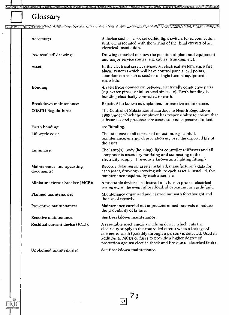
EGlossary
Accessory: A device such as a socket outlet, light switch, fused connectionunit, etc associated with the wiring of the final circuits of anelectrical installation.
`As-installed' drawings: Drawings marked to show the position of plant and equipmentand major service routes (e.g. cables, trunking, etc).
Asset: In the electrical services sense, an electrical system, e.g. a firealarm system (which will have control panels, call points,sounders etc as sub-assets) or a single item of equipment,e.g. a kiln.
Bonding: An electrical connection between electrically conductive parts(e.g. water pipes, stainless steel sinks etc). Earth bonding isbonding electrically connected to earth.
Breakdown maintenance: Repair. Also known as unplanned, or reactive maintenance.
COSHH Regulations: The Control of Substances Hazardous to Health Regulations1989 under which the employer has responsibility to ensure thatsubstances and processes are assessed, and exposures limited.
Earth bonding: see Bonding.
Life-cycle cost: The total cost of all aspects of an action, e.g. capital,maintenance, energy, depreciation etc over the expected life ofthe asset.
Luminaire: The lamp(s), body (housing), light controller (diffuser) and allcomponents necessary for fixing and connecting to theelectricity supply. (Previously known as a lighting fitting.)
Maintenance and operating Records detailing all assets installed, manufacturer's data fordocuments: each asset, drawings showing where each asset is installed, the
maintenance required by each asset, etc.
Miniature circuit-breaker (MCB): A resettable device used instead of a fuse to protect electricalwiring etc in the event of overload, short-circuit or earth-fault.
Planned maintenance: Maintenance organised and carried out with forethought andthe use of records.
Preventive maintenance: Maintenance carried out at predetermined intervals to reducethe probability of failure.
Reactive maintenance: See Breakdown maintenance.
Residual current device (RCD): A resettable mechanical switching device which cuts theelectricity supply to the controlled circuit when a leakage ofcurrent to earth (possibly through a person) is detected. Used inaddition to MCBs or fuses to provide a higher degree ofprotection against electric shock and fire due to electrical faults.
Unplanned maintenance: See Breakdown maintenance.
761
4
Addresses of professional associations
The Association of Consulting EngineersAlliance House, 12 Caxton Street, London SW1H OQL
Chartered Institution of Building Services EngineersDelta House, 222 Balham High Road, London SW12 9BS
The Electrical Contractors' AssociationESCA House, 34 Palace Court, London W2 4HY
The Institution of Electrical and Electronics Incorporated EngineersSavoy Hill House, Savoy Hill, London WC2R OBS
The Institution of Electrical EngineersSavoy Place, London WC2R OBL
National Inspection Council for Electrical Installation Contracting37 Albert Embankment, London SE1 7UJ
621,1
5
Tel. 071-222 6557
Tel. 081-675 5211
Tel. 071-229 1266
Tel. 071-836 3357
Tel. 071-240 1871
Tel. 071-582 7746
References
9. 9.
10.
11.
12.
13.
14.
15.
16.
17.
18.
19.
20.
21.
22.
23.
24.
25.
Building Bulletin 70: Maintenance and Renewal in Educational Buildings: Maintenance of MechanicalServices, Architects and Building Branch, Department of Education and Science, HMSO, 1990.Maintenance Expenditure 1990, Society of Chief Architects of Local Authorities, 1991.
Inspection and Testing of Electrical Installations in Local Authority Premises, Society of Chief Electricaland Mechanical Engineers, November 1989.
Electricity at Work Regulations 1989, Statutory. Instrument 1989/635, HMSO.
Circular No. 7/88: Education Reform Act: Local Management of Schools, September 1988. Department ofEducation and Science.
Design Note 40: Maintenance and Renewal in Educational Buildings: Needs and Priorities,Architects and Building Branch, Department of Education and Science, 1985.
BS 3811: 1986: Glossary of Maintenance Management Terms in Terotechnology, British StandardsInstitute.CISBE Guide, Section B18: 'Owning and operating costs', Chartered Institution of Building ServicesEngineers, 1986.BS 6396: 1990: Electrical systems in office furniture and office screens, British Standards Institute.
Lighting Guide LG3: Areas for visual display terminals, Chartered Institution of Building ServicesEngineers, 1989.IEE Wiring Regulations: Regulations for Electrical Installations, 16th edition, The Institution ofElectrical Engineers, 1991.Guidance Note GS23: Electrical Safety in Schools (Electricity at Work Regulations 1989), Health andSafety Executive, 1990.
Consortium of Local Education Authorities for the Provision of Science Services (CLEAPSS),Laboratory Handbook, Schools Science Service at Brunel University, Uxbridge UB8 3PH.
Design Note 17: Guidelines for environmental design and fuel conservation in educational buildings,Architects and Building Branch, Department of Education and Science.
Building Bulletin 73: Maintenance and Renewal in Educational Buildings: A Guide to Energy EfficientRefurbishment, Architects and Building Branch, Department of Education and Science, HMSO, 1991.
BS 6423: 1983: Maintenance of electrical switchgear and control gear for voltages up to 650V, BritishStandards Institute.BS 1363: 1984: Specification for 13A fused plugs and switched and unswitched socket-outlets, BritishStandards Institute.BS 4343: 1968: Specification for industrial plugs, socket-outlets and couplers for ac and dc supplies,British Standards Institute.CIBSE Code for Interior Lighting, Chartered Institution for Building Services Engineers, 1984.
BS 5266: Part 1: 1988: Emergency lighting, British Standards Institute.
Building Bulletin 7: Fire and the design of educational buildings, Architects and Building Branch,Department of Education and Science, HMSO, 1988.
BS 5839: Fire detection and alarm systems for buildings, Part 1: 1988: Code of practice for system design,installation and servicing, British Standards Institute.
Building Bulletin 69: Crime Prevention in Schools: Specification, Installation and Maintenance ofIntruder Alarm Systems, Architects and Building Branch, Department of Education and Science,HMSO, 1989.
BS 4737: Intruder alarm systems: Section 4.2: 1986: Code of practice for maintenance and records, BritishStandards Institute.Guidance Note PM32: The safe use of portable electrical apparatus (electrical safety), Health and SafetyExecutive, 1990.
63
7 R
26. BS 5304: 1988: Code of practice for safety of machinery, British Standards Institute.
27. Control of Substances Hazardous to Health Regulations, SI 1988/1657, HMSO.
28. BS 6651: 1990: Code of practice for protection of structures against lightning, British Standards Institute.
29. Guidance Note PM7: Lifts: Thorough inspection and testing, Heath and Safety Executive, 1982.
30. BS 5655: Lifts and service lifts, British Standards Institute.
Printed in the United Kingdom for HMSO.Dd.0295069, C15, 6/92, 3385/4, 5673, 196859.
64
ftr
This Bulletin will be helpful to Heads,,governing bodies, LEAs, consultants andothers involved with the maintenance ofelectrical services in schools.
It emphasises the importance of safety andgives guidance on the development of anoverall strategy to cover record documentationand systems, inspection and testing, conditionappraisal, maintenance requirements andmaintenance works procedures.
Further sections deal briefly vith topics suchas educational requirements, energy,community use, spare capacity and tasksfoi- school staff.
HMSO publications are available from:
HMSO Publications Centre(Mail, fax and telephone orders only)PO Box 276, London, SW8 5DTTelephone orders 071-873 9090General enquiries 071-873 0011(queuing system in operation for both numbers)Fax orders 071-873 8200
HMSO Bookshops49 High Holborn, London, WC1V 6HB071-873 0011 Fax 071-873 8200 (counter service only)258 Broad Street, Birmingham, B1 2HE021-643 3740 Fax 021-643 6510Southey House, 33 Wine Street, Bristol, BSI 2BQ0272 264306 Fax 0272 2945159-21 Princess Street, Manchester, M60 8AS061-834 7201 Fax 061-833 063416 Arthur Street, Belfast. BT1 4GD0232 238451 Fax 0232 23540171 Lothian Road, Edinburgh, EH3 9AZ031-228 4181 Fax 031-229 2734
HMSO's Accredited Agents(see Yellow Pages)
and through good booksellers
't
BESTCOPYAVAILABLE9
ISBN 0- 1-270799-8
780112 711
07998
U.S. Department of EducationOffice of Educational Research and Improvement (OERI)
National Library of Education (NLE)
Educational Resources Information Center (ERIC)
NOTICE
Reproduction Basis
ERIC
This document is covered by a signed "Reproduction Release(Blanket)" form (on file within the ERIC system), encompassing allor classes of documents from its source organization and, therefore,does not require a "Specific Document" Release form.
This document is Federally-funded, or carries its own permission toreproduce, or is otherwise in the public domain and, therefore, maybe reproduced by ERIC without a signed Reproduction Release form(either "Specific Document" or "Blanket").
EFF-089 (3/2000)