reproduction or transmission of all written consent, is ... reproduction or transmission of all ......
TRANSCRIPT

A non-transferable, non-exclusive licence to use this content was purchased by
the customer whose details are displayed at the top of each page.
Reproduction or transmission of all or part of the content, whether by
storing in any medium by electronic means or otherwise, without our prior
written consent, is prohibited.
The commission of any unauthorised act in relation to the content may result in civil or criminal actions.
Essential Knowledge Series
Essential Knowledge Text No. 16
Stability
David Cormie

Published by: The Institution of Structural Engineers47–58 Bastwick StreetLondon EC1V 3PSUnited KingdomT: +44(0)20 7235 4535E: [email protected]: www.istructe.org
First published: September 2016This version (1.0) published: September 2016
© 2016 David Cormie (pre-publication version) and published under a non-exclusive licence by The Institution of Structural Engineers
The Institution of Structural Engineers and those individuals who contributed to this Essential Knowledge Text have endeavored to ensure the accuracy of its contents. However, the information presented should always be reviewed by those using the Text in the light of the facts of their particular case and specialist advice obtained as necessary. No liability for negligence or otherwise in relation to this Text and its contents is accepted by the Institution, the author, the reviewers, their servants or agents.
No part of this publication may be reproduced, stored in a retrieval system or transmitted in any form or by any means without prior permission of The Institution of Structural Engineers, who may be contacted at 47–58 Bastwick Street, London EC1V 3PS, United Kingdom.
AcknowledgementsAuthorDavid Cormie MEng(Hons) CEng CEnv FIStructE FICE MASCE (Arup)
ReviewersBob Lark BSc(Eng) ACGI PhD CEng FICE (Cardi� University)John Nolan BSc MSc DEng(Hons) CEng FIStructE MICE (Nolan Associates)Andrew Weir BEng(Hons) MSc DIC CEng MIStructE MICE (Expedition Engineering)
Series EditorGraham Owens FREng FIStructE CEng MSc PhD DIC FRSA
PermissionsPhotographs and other digital imagery have been supplied courtesy of the author, with the exception of:
Figure 2.1 epa/Holland Luchtfoto Figure 2.2 PA Images Figure 2.4 BPM Media Wales
Stability

ContentsSynopsis 2
Terminology and de�nitions 3
1. Why stability? 41.1 Equilibrium and stability 51.2 Interaction between stability and resistance to horizontal loads 81.3 Stable and unstable structures 8
2. Failures due to lack of stability 132.1 FC Twente roof collapse, Enschede, The Netherlands, 2011 142.2 Hartford Civic Center Coliseum, Connecticut, USA, 1978 142.3 Cleddau Bridge, Milford Haven, Wales, 1970 16
3. Overall stability systems 193.1 Types of stability system 203.2 Types of plan bracing 283.3 Types of vertical bracing 303.4 Continuity of load paths 31
4. Designing for stability — global system design 324.1 Loads 334.2 Global system design 334.3 Dynamic e�ects 36
5. Designing for stability — local element design 375.1 Introduction 385.2 Strut buckling 385.3 E�ective length 405.4 Compressive strength 415.5 Validity of Euler’s theory — Perry-Robertson formula 415.6 Lateral-torsional buckling 425.7 Torsional buckling 435.8 Flexural-torsional buckling 435.9 Local buckling 445.10 Notional horizontal loads 455.11 Eccentricities 465.12 Movement and tolerances 46
6. Conclusions 47
Stability
The Institution of Structural Engineers Essential Knowledge Text No. 16 1

Synopsis‘Stability’ is one of two fundamental requirements of a structure, the other being ‘equilibrium’. The lack of stability during construction or during the life of a structure can cause catastrophic structural failure. Stability is necessary against horizontal loads, asymmetric loading, out-of-plane loading and the e�ects of geometric imperfections, loading eccentricities and tolerances. The global stability system must form a core component of the overall structural design, and is accompanied by considerations to ensure the design of individual structural members.
Stability
2 The Institution of Structural Engineers Essential Knowledge Text No. 16

Terminology and definitionsBuckling: The transition of an axially-loaded element from stable to unstable. Mathematically, buckling is characterised by the occurrence of a bifurcation in the solution to the equations of static equilibrium. At the critical buckling load at which this bifurcation occurs, further load is able to be sustained in one of two states of equilibrium: a purely-compressed state or a laterally-deformed state.
Critical buckling load: The load at which buckling occurs.
Equilibrium: A state in which all internal and external forces and moments acting upon the structure are balanced, such that the resultant force at any point within the structure and on the structure as a whole is zero.
Instability: The inability of a structure to recover to an equilibrium state upon being disturbed by a small perturbation.
Neutrally stable: Description of an equilibrium state at which the transition between stability and instability occurs. If the system was in equilibrium and it is disturbed by a small perturbation, it remains in equilibrium.
Perturbation: An externally-imposed disturbance of an equilibrium state while actual loads are kept �xed. It may involve the application of either forces or motions.
Stability: The ability of a structure to recover to an equilibrium state upon being disturbed by a small perturbation.
Stable: Description of an equilibrium state or con�guration in which stability holds.
Unstable: Description of an equilibrium state or con�guration at which instability occurs.
Stability
The Institution of Structural Engineers Essential Knowledge Text No. 16 3

1.
Why stability?Here, the reader will learn the importance of considering the stability of structures and their components.
4 The Institution of Structural Engineers Essential Knowledge Text No. 16

1.1 Equilibrium and stabilityA structure, to be successful, must be in equilibrium under the applied loads. The loads are usually applied in a range of combinations, termed ‘load cases’. A structure which is not in equilibrium is a mechanism. The cantilever in Figure 1.1 would form a mechanism if a pin were inserted at the base (Figure 1.2).
However, a successful structure is more than one which is in equilibrium. There is a second requirement — that it is also stable.
Figure 1.1: Simple cantilever column
Figure 1.2: Unstable mechanism
Stability
The Institution of Structural Engineers Essential Knowledge Text No. 16 5

The stable structure in Figure 1.3 returns to equilibrium after a small perturbation (movement) is applied. The acceleration of the body is back towards the position of equilibrium.
In the unstable system shown in Figure 1.4, the applied perturbation causes an acceleration away from the position of equilibrium.
Figure 1.3: Stable system
Figure 1.4: Unstable system
Stability
6 The Institution of Structural Engineers Essential Knowledge Text No. 16

A system may instead be neutrally stable (Figure 1.5). Here, the body continues to move after the perturbation is applied, neither accelerating nor decelerating. It remains in stable equilibrium.
A pendulum (Figure 1.6) is another stable system; after an external perturbation is applied, it oscillates about a position of static equilibrium until it eventually comes to rest.
Consider now the cantilever of Fig. 1.1: if no lateral loads could act, it would continue to be in equilibrium even after a pin were inserted at the base. In some respects this would be advantageous; by eliminating the moments it signi�cantly reduces the forces for which the foundations need to be designed. However, it would be unstable. Whereas the �xed-base system would return to its original position after a small perturbation, a small perturbation applied to the pin-ended cantilever would cause it to collapse. The system therefore lacks stability and violates one of the two fundamental requirements of a structure.
Figure 1.5: Neutrally stable system
Figure 1.6: Pendulum (and its response after a disturbing impact or displacement)
Stability
The Institution of Structural Engineers Essential Knowledge Text No. 16 7

While this is a simplistic example, it is clear that failing to design for stability results in a structure which is unsafe.
Note: The engineer could still avoid the need to design the foundation for overturning moments by adding guy cables (Figure 1.7). This is the common design of a radio mast — often with intermediate guys.
1.2 Interaction between stability and resistance to horizontal loadsAlthough the e�ects are separate and di�erent, there is a strong correlation between a structure’s resistance to horizontal loads and its overall stability.
For example, in Fig. 1.7, the guys will be necessary to resist wind loads acting on the mast. Once provided, they will also stabilise the structure under vertical loads. In general, if the ‘horizontal’ structure (i.e. the structure necessary to resist wind and other horizontal loads) is designed to conventional strength and sti�ness criteria, it is likely to be su�cient to provide overall stability under vertical loads. While this generally holds true, it cannot be assumed as such and so it is imperative that the stability system is considered and analysed separately.
1.3 Stable and unstable structuresThere are many ways in which a structure may resist horizontal loads and therefore be stabilised. Consider the eight sketches of simple frames (Figure 1.8a–h).
Figure 1.7: Guyed mast
Stability
8 The Institution of Structural Engineers Essential Knowledge Text No. 16
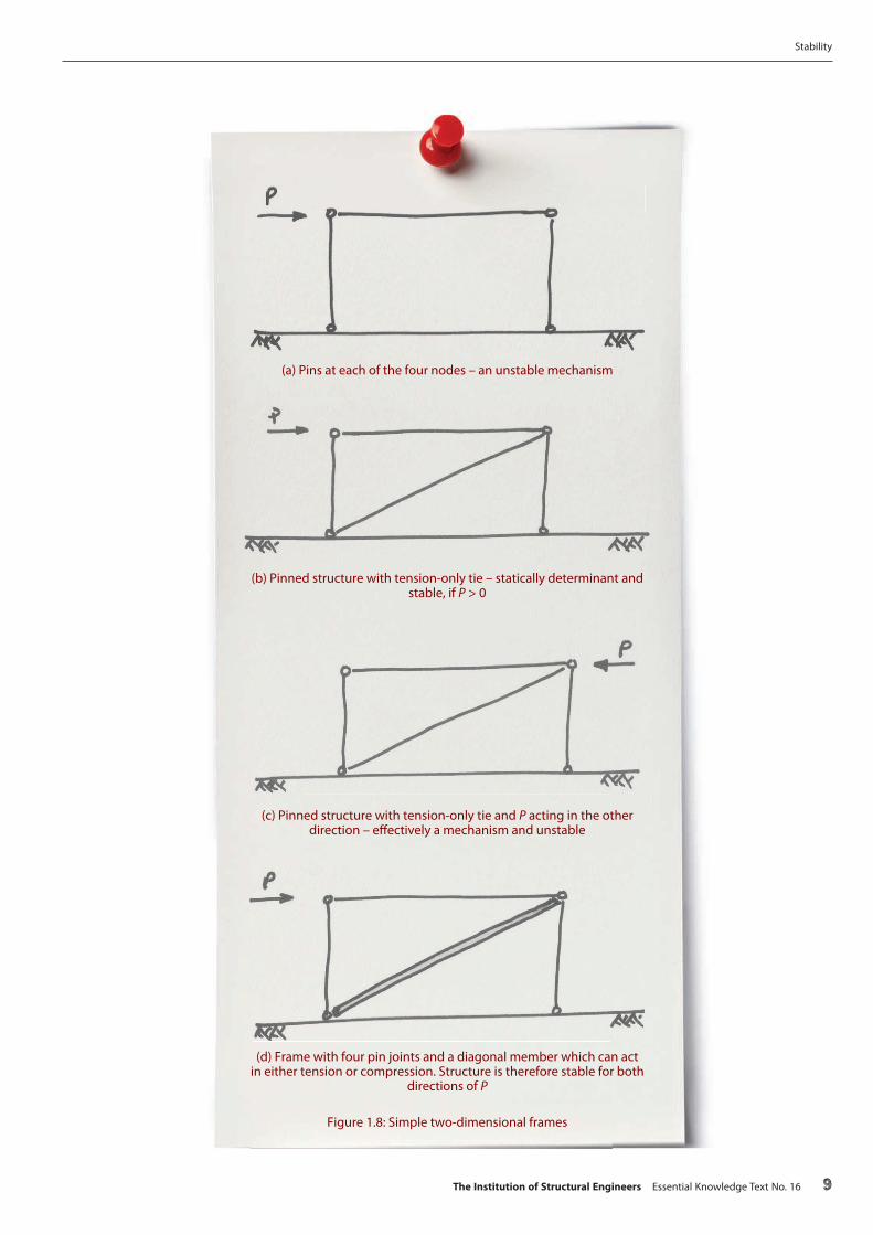
(a) Pins at each of the four nodes – an unstable mechanism
(b) Pinned structure with tension-only tie – statically determinant and stable, if P > 0
(c) Pinned structure with tension-only tie and P acting in the other direction – e�ectively a mechanism and unstable
(d) Frame with four pin joints and a diagonal member which can act in either tension or compression. Structure is therefore stable for both
directions of P
Figure 1.8: Simple two-dimensional frames
Stability
The Institution of Structural Engineers Essential Knowledge Text No. 16 9

(e) Frame with four pin joints and tension-only diagonal ties in both directions. Structure is stable for both directions of P
(f) One pinned node is replaced by a �xed joint. Structure is now statically determinate and stable for both directions of P
(g) Both upper pins are replaced by �xed joints (a more usual arrangement than the asymmetric structure of 1.8(f )). It is
statically indeterminate (with a degree of indeterminacy of 1) and therefore stable
(h) Two pin joints at the tops of the columns and �xed column bases. It is statically indeterminate (DOI of 1) and therefore stable
Figure 1.8 (continued): Simple two-dimensional frames
Stability
10 The Institution of Structural Engineers Essential Knowledge Text No. 16

The di�erent systems shown in Fig 1.8(d)–(f ) highlight an important point. Just as with the vertical loads, the selection of the ‘stability structure’ will have an impact on utility and economy, and is a decision for the engineer. The merits and disadvantages of each must be carefully weighed and considered.
Most structures are statically indeterminate. That is, they have redundancy which guards against failure and also leads to a more e�cient structural design: the simplest example is a continuous beam, which has two ‘degrees of indeterminacy’ (DOI) (Figure 1.9a). This means that two degrees of freedom can be released and the structure remains stable: if the two ends of the beam are released in the rotational (Myy) degree of freedom, the beam becomes simply supported and statically determinate (Figure 1.9b).
Not all instabilities are easy to identify. Consider a structure which is composed of four similar planar frames, each of which might be stable when analysed as a two-dimensional frame (Figure 1.10). The right-hand leg is �xed to provide in-plane stability. Out-of-plane, both legs are considered to be pinned and the frame is propped by the adjoining frame, which transfers the lateral load to the foundation through bending of the �xed leg. However, when analysed as a global system, a torsional instability becomes apparent (Figure 1.11).
(a) Statically indeterminate encastré beam (DOI of 2)
(b) Statically determinate simply-supported beam
Figure 1.9: Statically determinate and indeterminate structures
Stability
The Institution of Structural Engineers Essential Knowledge Text No. 16 11

2.
Figure 1.10: Structure stable in two dimensions
Figure 1.11: Structure unstable in three dimensions (horizontal reactions have been omitted for clarity)
Stability
12 The Institution of Structural Engineers Essential Knowledge Text No. 16

2.
Failures due to lack of stabilityThis section demonstrates the overriding importance of stability to structural safety by summarising three structures where instability caused catastrophic failure.
The Institution of Structural Engineers Essential Knowledge Text No. 16 13

2.1 FC Twente roof collapse, Enschede, The Netherlands, 2011On 7 July 2011, the roof of the FC Twente stadium in Enschede collapsed while under construction to extend the stadium2.1. The roof was an exoskeleton cantilever design built around an existing stand. It comprised eight trusses cantilevered above the new stand, stabilised out-of-plane by lateral bracing at the back ends of the trusses. At the time of the collapse, the roof was still under construction and was therefore not yet independently stable. As a result of failure to coordinate and control the construction sequence adequately, the lateral ties had not yet been installed, but steel cables used as temporary stabilising measures were removed just prior to the collapse. The roof was also subjected to additional load with the presence of piles of roof sheeting, access and maintenance gantries, display screen equipment and construction workers. The additional loading exceeded the limited load that the roof could sustain in the absence of the stabilising measures, and the combination of the forces in the structure (as a result of its self-weight and the additional load) caused one of the roof beams to fail, initiating a total collapse (Figure 2.1). Two workers were killed and more than a dozen injured.
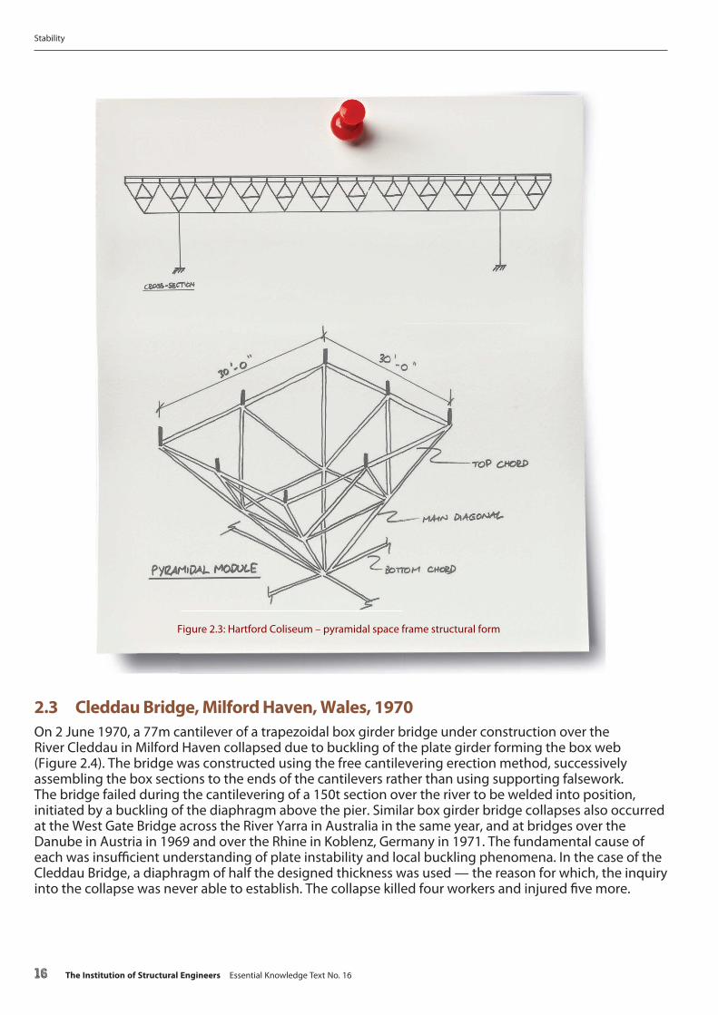
2.2 Hartford Civic Center Coliseum, Connecticut, USA, 1978The Hartford Civic Center Coliseum collapsed on 18 January 1978 (Figure 2.2) under snow from a 10 day storm which, while signi�cant, was not out of the ordinary. The construction of the building was completed in 1973 and had been used to host ice hockey games for �ve years. The roof was a pyramidal space frame, innovative at the time and noted for being one of the �rst large-span roofs made possible by computer design and analysis.
Figure 2.1: FC Twente stadium roof
Stability
14 The Institution of Structural Engineers Essential Knowledge Text No. 16

The roof was designed to span 82 × 64m over the arena, which seated 10,000 spectators. Horizontal chords were spaced 6.4m apart, diagonally braced with an intermediate layer of horizontal members providing stability to the diagonal bracing members (Figure 2.3). Back-to-back angle sections were used to form cruciform built-up sections for the main chord members, with o�sets between the node and the intersection of the bracing members due to the open nature of the chord sections. Computational analysis was used to verify the design against elastic buckling.
During construction, the inspection agency noti�ed the engineers that it had found excessive de�ection in some of the nodes and, in its �nal position, the measured de�ection was found to be twice that predicted by the analysis. However, the engineers stated that such discrepancies between the actual and the theoretical should be expected in view of the simplifying assumptions of the theoretical calculations.
The investigation into the collapse found that three major design errors in the original design contributed to the collapse. First, the nodes of the trusses were modelled with zero eccentricity, an incorrect assumption which placed additional stresses due to bending moments into the members, reducing their capacity. Second, compression members in the top chord were under-designed and braced against buckling in only one plane; the external compression members were unrestrained against buckling. Third, the self-weight of the roof was underestimated by 20% as 0.9kPa in the analysis, compared with an actual self-weight of 1.1kPa. A separate investigation also found that the torsional buckling capacity of compression members near the four roof buttresses was close to maximum. On the night of the collapse, the total load acting on the roof was 3.2–3.5kPa (of which the snow load was 0.7–0.9kPa), well below what the design capacity of the roof should have been without the errors, which was at least 6.7kPa2.2-2.4.
Figure 2.2: Hartford Civic Center Coliseum
Stability
The Institution of Structural Engineers Essential Knowledge Text No. 16 15
2.3 Cleddau Bridge, Milford Haven, Wales, 1970On 2 June 1970, a 77m cantilever of a trapezoidal box girder bridge under construction over the River Cleddau in Milford Haven collapsed due to buckling of the plate girder forming the box web (Figure 2.4). The bridge was constructed using the free cantilevering erection method, successively assembling the box sections to the ends of the cantilevers rather than using supporting falsework. The bridge failed during the cantilevering of a 150t section over the river to be welded into position, initiated by a buckling of the diaphragm above the pier. Similar box girder bridge collapses also occurred at the West Gate Bridge across the River Yarra in Australia in the same year, and at bridges over the Danube in Austria in 1969 and over the Rhine in Koblenz, Germany in 1971. The fundamental cause of each was insu�cient understanding of plate instability and local buckling phenomena. In the case of the Cleddau Bridge, a diaphragm of half the designed thickness was used — the reason for which, the inquiry into the collapse was never able to establish. The collapse killed four workers and injured �ve more.
Figure 2.3: Hartford Coliseum – pyramidal space frame structural form
Stability
16 The Institution of Structural Engineers Essential Knowledge Text No. 16

The Merrison Committee of Inquiry set up after the collapse found that BS 1532.5 (the only British steel bridge design and construction Code of Practice available at the time of construction) was inadequate for applications such as the Cleddau Bridge. As a result, the committee implemented Interim Design and Workmanship Rules which contained comprehensive rules for the stress analysis of box girders and the design of steel-plated components in complex stress �elds, which laid the foundation for a new British Standard, BS 54002.6, for bridge construction. Wide-ranging proposals for allocation of contractual responsibilities and independent checking of designs and erection methods, which underpin the system of independent checking used in structural design today, were also implemented2.7–2.10.
There are similarities between the collapse of the Cleddau Bridge and the 2007 collapse of the I-35W bridge over the Mississippi River in Minnesota, although the collapse of the latter occurred during the service life of the bridge, 40 years after its construction. The probable cause of the I-35W collapse was a fundamental error in the design of the gusset plates framing the compression chords into the nodes of the main truss. The under-sizing of the gusset plates led them to yield under a combination of increases in the weight of the bridge resulting from previous modi�cations, and substantial loads on the bridge on the day of the collapse. The failure of the gusset plates allowed the compression chords to shift laterally, initiating an instability which resulted in the total structural collapse of the span2.11–2.12.
Figure 2.4: Cleddau Bridge: buckling of plate girder
Stability
The Institution of Structural Engineers Essential Knowledge Text No. 16 17

References
2.1 Dutch Safety Board (2011) Collapsed roof Grolsch Veste, 7 July 2011 [online] Available at: www.onderzoeksraad.nl/en/onderzoek/1824/collapsed-roof-grolsch-veste-7-july-2011 (Accessed: 2 August 2016)
2.2 Rihani, S.A. (2013) Structural Failures – Hartford Coliseum [online] Available at: www.selicensure.org/what-were-doing/case-study/structural-failures-hartford-coliseum (Accessed: 2 August 2016)
2.3 Delatte, N.J. Beyond Failure: Forensic Case Studies for Civil Engineers, ASCE Press, 2009
2.4 Levi, M. and Salvadori, M. Why Buildings Fall Down: How Structures Fail, W.W. Norton & Company, 1994
2.5 BS 153-3A:1954 Speci�cation for steel girder bridges. Loads. London: BSI, 1954
2.6 BS 5400-2:1978 Steel, concrete and composite bridges. Speci�cation for loads. London: BSI, 1978
2.7 Firth, I. (2010) ‘James Sutherland History Lecture: Lessons from history – the steel box girder story’, The Structural Engineer, 88(5), pp. 18–24
2.8 Department of the Environment (Merrison Committee of Inquiry). Inquiry into the Basis of Design and Method of Erection of Steel Box Girder Bridges. London: HMSO, 1973
2.9 Flint A.R. Steel Box Girder Bridges [online] Available at: www.webcitation.org/5VF7gzFhl (Accessed: 2 August 2016)
2.10 Bridle, R.J. and Sims, F. The e�ect of bridge failures on UK technical policy and practice. Proceedings of the Institution of Civil Engineers — Engineering History and Heritage, 162(1) pp. 39–49
2.11 National Transportation Safety Board. Accident report NTSB/HAR-08/03: Collapse of I-35W Highway Bridge Minneapolis, Minnesota, August 1, 2007 [online] Available at: www.ntsb.gov/investigations/AccidentReports/Reports/HAR0803.pdf (Accessed: 2 August 2016)
2.12 Brady, S. (2013) ‘The I-35W Highway Bridge collapse: lessons learned’, The Structural Engineer, 91(10), pp. 36–37
Stability
18 The Institution of Structural Engineers Essential Knowledge Text No. 16

3.
Overall stability systemsBefore considering any aspect of detailed design for stability, it is necessary for the engineer to conceive a structure which is capable of being stabilised.
The Institution of Structural Engineers Essential Knowledge Text No. 16 19

3.1 Types of stability system3.1.1 Braced frame
In the multi-storey building illustrated in Figure 3.1, it is often economical to concentrate all the bracing within the core, which will always be required for vertical distribution of services and access via lifts and stairs.
The horizontal load path is as follows:
• Façade transfers the wind load to the edge of the slab
• Slab transfers the forces by diaphragm action to the building core (Figure 3.2)
• The core, usually near the centre of the building, acts in shear and bending to transfer forces to the foundations (Figure 3.3)
Figure 3.1: Plan of typical multi-storey building
Stability
20 The Institution of Structural Engineers Essential Knowledge Text No. 16

Figure 3.3: Core acting to transfer horizontal forces to foundations
Figure 3.2: Diaphragm action of �oor slab
Stability
The Institution of Structural Engineers Essential Knowledge Text No. 16 21

Where the core is o�set from the centre of the building, it may be necessary to add perimeter bracing, additional shear walls, a moment frame or multiple cores in order to control forces/moments and to limit de�ections (Figure 3.4).
Figure 3.5 shows how horizontal forces acting on the structure are transferred into the soil using di�erent types of foundation. types of foundation.
Figure 3.5: Reaction forces with di�erent types of foundation
(a) Deep basement (b) Foundation piles (c) Foundation raft
de�ections (Figure 3.4).
Figure 3.4: Di�erent strategies for structures with cores that are eccentric to building centroid
Stability
22 The Institution of Structural Engineers Essential Knowledge Text No. 16

Braced cores are suitable for:
• Tall buildings requiring internal stairs and lifts
• Symmetrical/regular framed buildings
• Column-free spaces
• Buildings with a relatively small footprint
Braced cores are unsuitable for:
• Very tall buildings — outrigger columns connected to the core with deep beams may be needed to provide the required structure
• Seismic design — this structural arrangement possesses low ductility
3.1.2 Sway frames
Figure 3.6 shows a typical sway frame building where the perimeter beams on all four faces are rigidly connected to the supporting columns to form a moment frame.
The horizontal load path is as follows:
• Façade transfers the wind load to the edges of the slabs
• Slab acts as a diaphragm to transfer horizontal loads to the moment frames, usually on the perimeter
• Moment frames transfer the horizontal loads to the foundations (Figure 3.7)
Figure 3.6: Plan of typical building with perimeter sway frames
Stability
The Institution of Structural Engineers Essential Knowledge Text No. 16 23

Moment frames are suitable for:
• Seismic areas where high levels of ductility are required
• Multi-storey buildings without a central core, where diagonal bracing or shear walls cannot be concealed
Moment frames are unsuitable for:
• Buildings having a central core which would be su�cient as a stability system alone, because of the added cost of moment connections
3.1.3 Perimeter braced frame
Figures 3.8 and 3.9 show a typical plan and elevation for a building with perimeter bracing.
Figure 3.8: Plan of typical building with perimeter bracing
Figure 3.7: Sway action of perimeter frame
Stability
24 The Institution of Structural Engineers Essential Knowledge Text No. 16

The horizontal load path is as follows:
• Façade transfers the wind load to slab edge
• Slabs act as diaphragms to transfer loads to perimeter frames
• A system of perimeter cross bracing transfers loads to the foundations
Perimeter braced frames are suitable for:
• Buildings without a central core and where the perimeter bracing can be architecturally expressed
• Buildings which must accommodate transfer structures to omit/decrease columns at lower levels
Perimeter braced frames are unsuitable for:
• Seismic areas where high levels of ductility are required
3.1.4 Braced frames (cross bracing)
Figure 3.10 shows a typical low-rise building with cross bracing in some external panels, usually corner panels.
Figure 3.10: Typical low-rise building with perimeter cross bracing
Figure 3.9: Elevation of typical building with perimeter bracing
Stability
The Institution of Structural Engineers Essential Knowledge Text No. 16 25

The horizontal load path is as follows:
• Wall cladding transfers loads to sheeting rails which load the columns
• Roof cladding, sti�ened by purlins, acts in shear to transfer loads from intermediate frames to those containing cross bracing
• Eaves and internal beams prop internal frames to adjacent bay, in order to transfer load out of braced bays
• Braced bays (usually end bays) transfer load to foundations, usually with tension-only cross bracing
• Foundation transfers load out to soil
This form of braced frame is suitable for:
• Large plan area, low-rise buildings without internal cores
This form of braced frame is not suitable for:
• Multi-storey buildings
3.1.5 Portalised (sway) structures
Figure 3.11 shows the plan view of a typical portal frame structure.
The horizontal load path is as follows:
• Wall cladding transfers load to eaves level (and to ground)
• Roof cladding (sti�ened by purlins) acts in shear to transfer load between intermediate purlins
• Frame is portalised, usually in one direction only (usually the shorter span direction), transferring load applied through bending of the portal beam and column leg (Figure 3.12)
Figure 3.11: Typical single-storey portal frame building
Stability
26 The Institution of Structural Engineers Essential Knowledge Text No. 16

• Base is usually analysed as pinned to avoid generating large bending moments (though �xed base portals can achieve a greater clear span). In practice, the base has partial �xity due to four bolts provided for �xity in the temporary condition
• In the orthogonal (un-portalised) direction, eaves and ridge beams prop internal frames to adjacent bays, transferring load out to braced (usually end) bays
• Braced bays transfer load to foundation through diagonal (usually tension-only) cross bracing
• Foundation transfers load into soil
Greater spans may be achieved through internal spans placed every second or third portal. Multi-span portal frames may extend plan dimensions over several spans.
Figure 3.12: Dead and live load acting on the portal frame in Figure 3.11
Stability
The Institution of Structural Engineers Essential Knowledge Text No. 16 27
This structural arrangement is suitable for:
• Large-span, single-storey, column-free spaces
This structural arrangement is unsuitable for:
• Multi-storey buildings
• Buildings with a relatively small span-to-height ratio
• Buildings where internal columns are acceptable and can reduce the weight of the roof beams
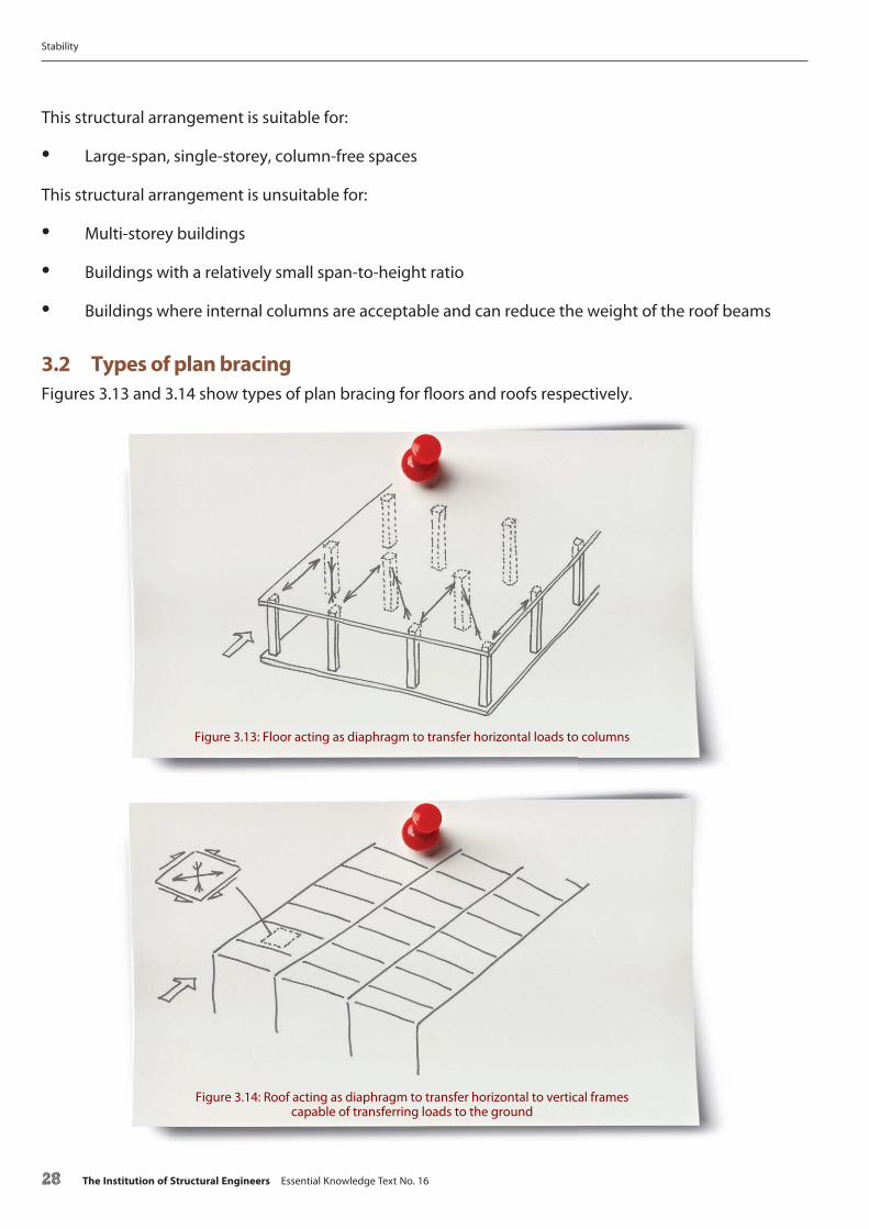
3.2 Types of plan bracingFigures 3.13 and 3.14 show types of plan bracing for �oors and roofs respectively.
Figure 3.13: Floor acting as diaphragm to transfer horizontal loads to columns
Figure 3.14: Roof acting as diaphragm to transfer horizontal to vertical frames capable of transferring loads to the ground
Stability
28 The Institution of Structural Engineers Essential Knowledge Text No. 16

As shown in Figures 3.15 and 3.16, the diagonals in the plan bracing in roofs may be capable of acting in both tension and compression or be only capable of carrying tension forces. In the latter case, the secondary roof beams need to act as struts for the horizontal truss to be e�ective.
Figure 3.15: Plan bracing in roof comprising tension and compression diagonals
Figure 3.16: Plan bracing in roof comprising tension-only diagonals
Stability
The Institution of Structural Engineers Essential Knowledge Text No. 16 29

3.3 Types of vertical bracingFigures 3.17–3.19 show the three principal methods of transferring horizontal forces vertically down the building to the foundations.
Figure 3.17: Concrete walls of core acting in shear and in-plane bending
Figure 3.18: Braced end bays of single storey building acting as trusses
Figure 3.19: Side frames of single storey building acting in bending and shear
Stability
30 The Institution of Structural Engineers Essential Knowledge Text No. 16

3.4 Continuity of load pathsLateral load paths should generally be continuous. Non-continuous load paths will often produce a complex set of forces and moments which are di�cult to predict (Figure 3.20). Load paths should usually be arranged in two, more or less orthogonal, directions through the structure and from the highest level down to the foundations.
In Fig. 3.20, the non-continuous vertical bracing system (perhaps to allow for the insertion of a window) produces some complex moments in the columns due to unresolved bracing forces. In Figure 3.21, the continuous bracing system allows all the bracing forces to be resolved internally.
Figure 3.20: Discontinuous braced bays inducing column bending under horizontal loads
Figure 3.21: Column bending eliminated by use of continuous braced bays
Stability
The Institution of Structural Engineers Essential Knowledge Text No. 16 31

4.
Designing for stability _ global system design
32 The Institution of Structural Engineers Essential Knowledge Text No. 16

4.1 LoadsStability must be considered under all the relevant load combinations. These may include:
• Dead load
• Live load
• Wind load (including dynamic e�ects)
• Seismic load
• Blast and impact load
• Notional eccentricities
• Accidental actions
• Thermal actions
• Fire condition
• Tolerance and movement
• Snow loading (including asymmetric/pattern loading)
• Tra�c loading (including pattern loading)
Stability must also be considered during construction and in any temporary conditions (e.g. maintenance). Stability during construction is often an issue for the contractor. However, stability during any maintenance situation is not. The designer must (under UK legislation) ensure a safe design throughout the life of the structure. As well as maintenance, this includes at least ensuring a viable construction sequence exists, even if the detail is taken forward by the contractor.
4.2 Global system designAs previously stated, the stability system must be checked under all the relevant load cases. The partial factors will be listed in the relevant code of practice; however, the engineer must ensure that the load cases analysed capture the worst-case conditions for all parts of the structure, as well as for the structure as a whole. Some of these are discussed in more detail in the following sub-sections.
4.2.1 Forces and moments
The forces and moments on the stability system must be calculated under each load case and resolved, to give the forces and moments for the design of individual members (Section 5). There will be several load cases; wind, for example, will produce at least four — one for each orthogonal direction. The combination of load types, e.g. wind in combination with (or in the absence of) live loading, in the presence/absence of snow loading and so on, will have di�erent partial factors representing the probability of their coincident action, that will further increase the number of load cases to be considered.
Stability
The Institution of Structural Engineers Essential Knowledge Text No. 16 33

Figure 4.1 illustrates one example where further thought needs to be given to determine the governing condition.
4.2.2 Displacements
Some actions, such as thermal expansion and contraction, notional eccentricities, movement and tolerances will produce displacements which must be considered in combination with some of the loads listed in Section 4.1. For example, lateral displacements applied to a slender column due to thermal expansion and contraction may reduce the buckling capacity of the column under axial, dead and live loading (Figure 4.2).
Figure 4.2: Reduced resistance to buckling from solar heating
Figure 4.1: Situations where line of action of horizontal forces does not act through line of resistance to horizontal loads
a) eccentric core b) di�erent sti�nesses in cores
Stability
34 The Institution of Structural Engineers Essential Knowledge Text No. 16

4.2.3 P–delta (P–Δ) e�ects
P–delta (P–Δ) e�ects occur in circumstances where the displacement of the structure a�ects either its sti�ness and/or the load distribution acting on it and therefore its position of equilibrium. These second-order e�ects must be taken into account when calculating the solution of static equilibrium. Increased bending moments, axial and shear forces are associated with increased strains and in some cases can overload the structure. An example is shown in Figure 4.3.
The same can happen with shallow arches; the displacement of the arch can cause a snap-through buckling failure (Figure 4.4) even if the supports are rigid. Such systems are particularly vulnerable to this type of failure if there is any non-uniformity in loading, due to gusts of wind, ponding of water or snow drift.
Second-order e�ects can also in�uence column behaviour. Consider the vertical cantilever under combined lateral and axial load where Fx << Fz (Figure 4.5). The lateral displacement due to bending from Fx and the axial shortening due to Fz from a �rst-order solution will be small. It is assumed that Fz is less than the Euler buckling load of the strut (Section 5).
Figure 4.3: ‘Snap-through buckling’ of shallow portal frame that will be predicted by second-order analysis
Figure 4.4: Snap-through buckling failure of shallow arch due to wind gust hitting roof at end A
Stability
The Institution of Structural Engineers Essential Knowledge Text No. 16 35

In the second-order solution of the same system, the lateral displacement due to Fx means that an additional bending moment is induced by Fz. Since EI is small, the e�ect of this second-order moment is large and the lateral displacement is signi�cantly increased. In this case, the second-order moment exceeds the �rst-order moment and, if the bending moment is sized only for the moment due to Fx, the column will fail due to these second-order e�ects.
4.3 Dynamic e�ectsSome types of dynamic loading can allow instabilities to develop, typically if the dynamic oscillation is at a frequency which causes resonance in the system.
Some notable examples are:
• Wind induced dynamic oscillation — Tacoma Narrows Bridge, Washington, USA, 1940. This is probably the most famous example of a dynamically-induced instability whereby the forces acting on the bridge induced negative damping, in which the developed wind forces were strongly linked to the structural motion and led to structural collapse
• Vibration of Bailey and other bridges. Marching troops are, famously, ordered to ‘break step’ when crossing bridges, particularly those with low natural frequencies and low mass, such as the Bailey Bridge developed by the British armed forces during the Second World War
• Synchronous lateral footfall-induced vibration — Millennium Bridge, London, UK, 2000. Shortly after opening, the Millennium Bridge su�ered unexpected lateral movements which were found to be due to lateral forces exerted by pedestrians on the deck, and an unconscious tendency of pedestrians to match their footsteps to become synchronous to the sway, thereby exacerbating its amplitude
Figure 4.5: Vertical cantilever under combined vertical and horizontal load
Stability
36 The Institution of Structural Engineers Essential Knowledge Text No. 16

5.
Designing for stability _ local element design
The Institution of Structural Engineers Essential Knowledge Text No. 16 37

5.1 IntroductionOnce the structural form has been arranged and the forces and moments under the load cases acting upon it calculated, the individual elements must each be designed for those forces and moments.
Within the element design, stability criteria must be considered. This Section outlines some of those criteria and the underlying principles.
5.2 Strut bucklingA perfectly straight elastic strut under a perfectly axial load will remain straight until the axial load reaches a critical value (Figure 5.1). At this critical value the strut is in equilibrium but will also be in equilibrium under an adjacent, slightly displaced, state — a state of neutral equilibrium is reached. This is a structural example of the ball on the �at surface shown in Fig. 1.5. If the load is increased above this critical load, this slight displacement produces an increasing moment on the strut which exacerbates the displacement; buckling results. This critical axial load is known as the ‘Euler buckling load’.
As shown in Fig. 5.1, the bending moment, M, = Py for statical equilibrium.
Since
M ¼ �EIðd2yÞðdx2Þ
then
Py þ EIðd2yÞðdx2Þ ¼ 0
This is a di�erential equation with the general solution
y = A sin αx + B cos αx
Figure 5.1: Euler buckling of pin-ended strut
Stability
38 The Institution of Structural Engineers Essential Knowledge Text No. 16
where
a ¼ffiffiffiffiP
EI
r
Since y = 0 at x = 0, B = 0.
Since y = 0 at x = L, for non-trivial solutions:
sin αL = 0, leading to αL = 0, π, 2π, 3π etc.
ð αL = nπ, where n = 1, 2, 3 etc.
and since and since a ¼ffiffiffiffiffiffiffiffiffiP=EI
p,
P ¼ n2p2 EI
L2
The least value of P (>0) corresponds to n = 1, giving the lowest critical load as
Pcrit ¼ p2 EI
L2
— the Euler load.
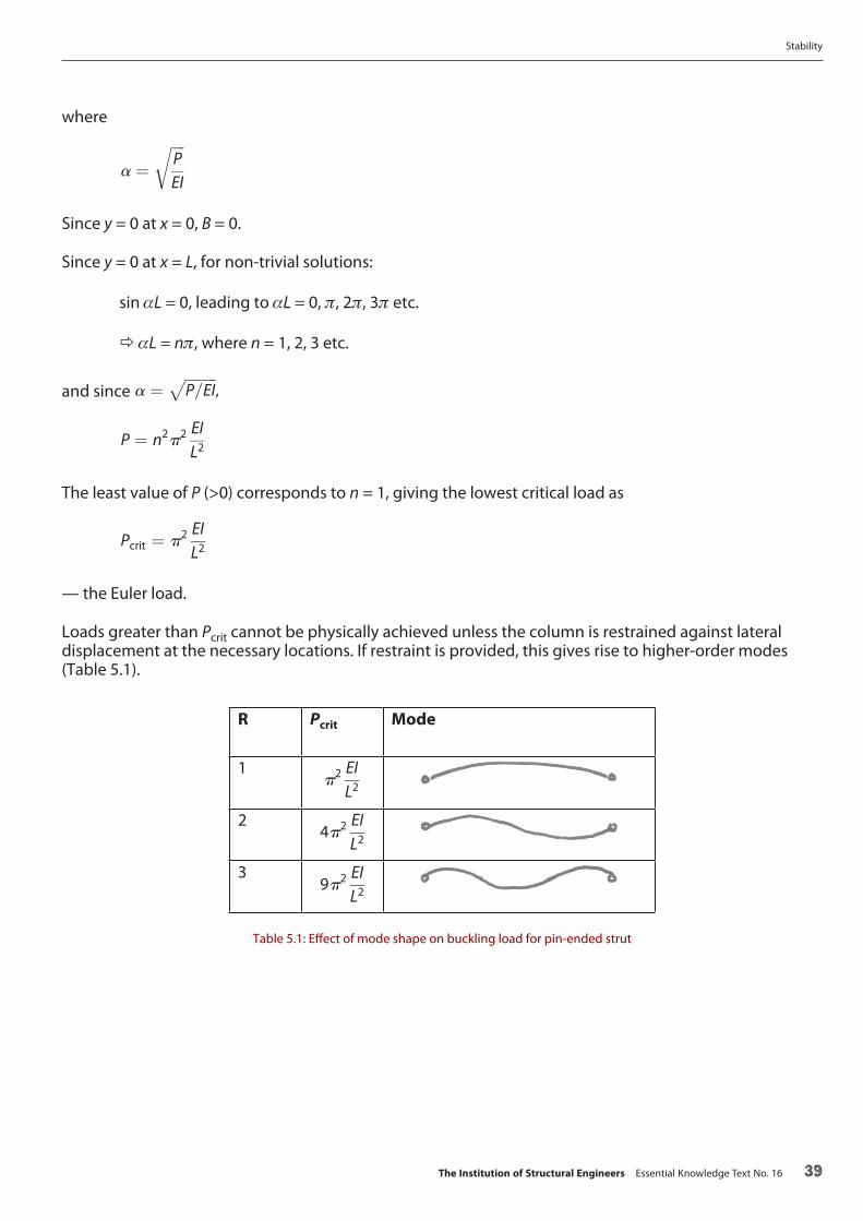
Loads greater than Pcrit cannot be physically achieved unless the column is restrained against lateral displacement at the necessary locations. If restraint is provided, this gives rise to higher-order modes (Table 5.1).
R Pcrit Mode
1p2 EI
L2
24p2 EI
L2
39p2 EI
L2
Table 5.1: E�ect of mode shape on buckling load for pin-ended strut
Stability
The Institution of Structural Engineers Essential Knowledge Text No. 16 39

5.3 E�ective lengthFor other support conditions, an ‘e�ective length’ can be derived. The e�ective length is the length of a pin-ended strut of the same EI which has the same critical load. Figure 5.2 shows how the concept is applied to a column with a rigid connection at its base.
Table 5.2 shows the theoretical e�ective lengths for common types of support conditions and compares them with the recommendations for design.
End conditions
E�ective length (theoretical) 1.0 0.5 0.7 2.0E�ective length (recommended) 1.0 0.7 0.85
Table 5.2: Theoretical and practical e�ective lengths for columns with di�erent end conditions
Figure 5.2: Comparison of mode shapes for pin-ended column, and column with �xed base
Stability
40 The Institution of Structural Engineers Essential Knowledge Text No. 16

5.4 Compressive strengthIf a perfect strut reaches its yield strength before the critical buckling load, it cannot buckle and is termed ‘stocky’. This leads to Figure 5.3, in which λ is the slenderness ratio given as λ = LE/r, where LE is the e�ective length and r is the radius of gyration, r = √(I/A).
5.5 Validity of Euler’s theory — Perry-Robertson formulaEuler buckling takes no account of residual stresses and geometric imperfections, which are signi�cant for λ < 80. A more complex formulation, accounting for these e�ects, is the Perry-Robertson formula, which is similar in form to the approach adopted in BS EN 19935.1.
It has the form
PcrA
¼sy þ ð1þ hÞsE
2�
ffiffiffiffiffiffiffiffiffiffiffiffiffiffiffiffiffiffiffiffiffiffiffiffiffiffiffiffiffiffiffiffiffiffiffiffiffiffiffiffiffiffiffiffiffiffiffiffiffiffiffiffiffiffiffiffi�sy þ ð1þ hÞsE
2
�2
� sysE
s
in which
σy is the yield strength of the material
σE is the compressive stress corresponding to the Euler buckling load
A is the area of the section, and
h ¼ 0:3
�LE
100r
�2
Di�erent imperfection factors may also be included in this formulation and their account is covered in BS EN 1993-1-15.2.
Figure 5.3: Upper bounds on column capacity for columns of di�ering slenderness
Stability
The Institution of Structural Engineers Essential Knowledge Text No. 16 41

5.6 Lateral-torsional bucklingAn unrestrained beam undergoing �exure may be sensitive to a lateral-torsional buckling mode if Iyy > Izz. This is an instability characterised by both lateral and torsional deformations caused by the compression acting in the compression �ange of the beam (Figure 5.4).
The critical lateral-torsional buckling moment, MLT, can be derived as:
MLT ¼
ffiffiffiffiffiffiffiffiffiffiffiffiffiffiffiffiffiffiffiffiffiffiffiffiffiffiffiffiffiffiffiffiffiffiffiffiffiffiffiffiffiffiffiffiffip2EIZZL2CR
�GIT þ
p2EIWL2
�s
where
Izz is the minor axis moment of inertia of the section
IT is the St Venant torsional inertia and for open sections has the general form IT = ∑ bt3/3 for open sections comprising plates of lengths b and thicknesses t
IW is the warping constant
G is the shear modulus
LE is the e�ective length
Figure 5.4: Beam subject to lateral-torsionalbuckling
Stability
42 The Institution of Structural Engineers Essential Knowledge Text No. 16

The similarity of the mathematical form with the Euler buckling equation is immediately apparent, as is the relationship of the critical buckling moment to the end conditions through the e�ective length LE. Also of note are the torsional moment of inertia and the warping constant. Sections which are torsionally weak, or are susceptible to warping (open sections), are signi�cantly more prone to lateral-torsional buckling (Figure 5.5).
5.7 Torsional bucklingTorsional buckling of columns can occur when a section is very weak in torsion, and leads to the column rotating about the force axis. This is rare in structural design but can occur, for example in the design of cruciform sections which lack any signi�cant torsional resistance.
5.8 Flexural-torsional bucklingFlexural-torsional buckling can occur in the design of open sections loaded in compression, and is characterised by the simultaneous bending and twisting of the section. It is similar to Euler strut buckling, with the addition of a torsional mode in the response. It occurs in open members in which the shear centre does not coincide with the centroid of the section, such as single- and double-angles, structural tees and channels. Asymmetric I-sections are all prone to �exural-torsional buckling, and the �exural-torsional buckling load can be lower than the critical strut buckling load.
It is distinct from lateral-torsional buckling, which is a lateral buckling mode that occurs in members loaded in bending about their major axis (see Section 5.6).
Figure 5.5: Open-section warping under torsion
Stability
The Institution of Structural Engineers Essential Knowledge Text No. 16 43

5.9 Local bucklingLocal buckling of plates can be an issue whenever the plates are unrestrained out-of-plane. This can occur in many circumstances; examples are illustrated in Figures 5.6 and 5.7.
Codes of practice contain slenderness limits for di�erent types of element (outstand element, internal element) under di�erent loading arrangements (bending, compression, shear etc). Typically these are expressed as width-to-thickness (d/T) ratios. Rules are also available for the e�ective width of element which should be considered. The limiting slenderness ratios are a function of the material yield strength, py. Typical values are given in Table 5.3, for the local dimensions shown in the accompanying diagram.
Figure 5.6: Local buckling of unsti�ened outstand
Figure 5.7: Buckling of slender web
Stability
44 The Institution of Structural Engineers Essential Knowledge Text No. 16

Class 1 plastic
Class 2 compact
Class 3 semi-compact
Class 4 slender
Outstand �ange 9ε 10ε 14ε – c/tf
Web (bending) 72ε 83ε 142ε – c/tw
Web (compression) 33ε 38ε 42ε – c/tw
where 1 ¼ffiffiffiffiffiffiffiffiffiffiffiffiffiffiffiffiffiffiffiffiffiffiffi
235
fyðN=mm2Þ
s
tf
tw d h
r
Bc
Table 5.3: Typical slenderness limits for local element design
Notes:
• A Class 1 section can develop the plastic moment capacity of the section and can sustain signi�cant rotation
• A Class 2 section can develop the plastic moment capacity but cannot sustain signi�cant rotation without buckling
• A Class 3 section can develop the elastic moment capacity but will buckle before the plastic moment capacity can be achieved
• A Class 4 section will buckle before the elastic moment capacity can be developed
5.10 Notional horizontal loadsNotional horizontal loads are an important preventative requirement in the design of structures against instability. In most modern codes of practice, notional horizontal loads must be applied in various con�gurations even where there is no conceived load which could give rise to such a condition. Accounting for only a few percent of the load carried by the member, analysing for the notional horizontal load helps to identify issues such as P–Δ (second-order geometric) e�ects, and the e�ects of lack of �t and geometric imperfection, movement and tolerance in the design.
Stability
The Institution of Structural Engineers Essential Knowledge Text No. 16 45

6.
5.11 EccentricitiesRarely, if ever, will loads acting on a member be truly axial or applied at the notional location of a pin. Analysis will often neglect such eccentricities, assuming columns to be loaded perfectly axially and joints to be perfectly concentric, such that all loads intersect at the centre of the node. A root cause in many past structural failures such as the Hartford Coliseum (Section 2.2) is the failure to take into account such eccentricities, and it is essential that, as the design is progressed through detailed design, the real o�sets are examined and the additional moments they generate accounted for. Even where eccentricities are negligible, imperfections in the design, fabrication and construction of the structure can give rise to additional forces and moments. Consequently, most modern codes of practice place a requirement for minimum eccentricities to be considered in the analysis of the structure, as mitigation against such conditions.
5.12 Movement and tolerancesMovement and tolerances can a�ect the stability of the �nal design to a signi�cant extent, generating additional forces which are often magni�ed as the construction progresses. A simple and common example is the serviceability de�ection of supports, such as steel beams or decking, during placement of a concrete slab, which causes ponding of the concrete towards the middle. As concrete is placed, the supporting system de�ects and more concrete is placed to compensate for the de�ection, further adding to the beyond-design load on the supporting beams/decking. In extreme cases, this over-placement of concrete in the centre of the slab can increase the dead load on the structure by 20% or more, such that the slab is overloaded under dead load and the live load capacity is correspondingly, and perhaps critically, reduced.
The structural engineer must consider the stability of the structure at all stages of construction and during the life of the structure, considering whether either temporary or permanent movements and the take-up of tolerances will have an adverse e�ect. The tolerances permitted in the construction of the structure must be speci�ed to ensure that the secondary forces are no greater than assumed in the structural design calculations. In some cases, particularly in long-span structures where tolerances can generate signi�cant secondary forces, the tolerances required will be tighter than standard limits.
References
5.1 BS EN 1993: Eurocode 3: Design of steel structures. London: BSI, 1993
5.2 BS EN 1993-1-1: Eurocode 3: Design of steel structures – General rules and rules for buildings. London: BSI, 1993
Stability
46 The Institution of Structural Engineers Essential Knowledge Text No. 16

6.
Conclusions
The Institution of Structural Engineers Essential Knowledge Text No. 16 47

For a successful structural design, stability must be considered throughout the entire design process. The following is a summary of the key considerations discussed in this Text:
• The stability system is an inherent part of the structure. Without it, the structure is unstable and collapse is inevitable
• There are two essential requirements of a structure: equilibrium, and stability. It is rare for either to be maintained without the other
• The lateral stability system must be considered from the outset of the design. The structural form, design constraints and loading conditions will de�ne the most suitable stability system, which can be grouped into two main types: ‘braced’ and ‘sway’. Each principal type and its variants have characteristics which lend themselves to particular conditions
• Stability must be considered in the temporary and permanent conditions. While design for temporary conditions during construction is often a matter for the contractor, it is the structural engineer’s responsibility to ensure that there is a safe method of construction. Many failures occur during construction, and while instability may be the fundamental cause of the failure, a glance at the examples in this Text and elsewhere show the unstable condition often arises because of a lack of coordination of the design
• Analysis must be appropriate to the structure being designed. There are many examples where poor analytical methods can severely under-predict the strains in a structure with instabilities inherent in the design neither being identi�ed nor addressed
• Stability must also be considered in the design of individual elements and their connections. Strut buckling, lateral-torsional buckling and local buckling of plates, webs and �anges can each arise wherever there are compression stresses present either locally or globally in the design of an element
• Eccentricities, notional horizontal loads, geometric imperfections, movement and tolerances will all exacerbate the forces and moments to which a structure is subjected. Analysis and design must recognise and account for these e�ects in the design and detailing of the structure
• Instabilities will sometimes occur under a dynamic, rather than a static, loading condition. Structures that interact with external (or internal) �uid �ows, and all structures that are subject to other forms of oscillatory motion such as footfall, vibration and seismic loading, can be subject to dynamic instabilities. Where such conditions exist, the design will require specialist input to identify and resolve potential causes
Further readingThe Institution of Structural Engineers. Stability of buildings Parts 1 and 2: General philosophy and framed bracing. London: IStructE Ltd, 2014
The Institution of Structural Engineers. Stability of buildings Part 3: Shear walls. London: IStructE Ltd, 2015
The Institution of Structural Engineers. Stability of buildings Part 4: Moment frames. London: IStructE Ltd, 2015
The Institution of Structural Engineers. Structural design – achieving excellence. London: IStructE Ltd, 2015
The Institution of Structural Engineers. Manual for the design of steelwork building structures to Eurocode 3. London: IStructE Ltd, 2010
Trahair, N.S., Bradford, M.A., Nethercot, D.A. and Gardner, L. The Behaviour and Design of Steel Structures to EC3, 4th ed. Abingdon: CRC Press, 2007
Stability
48 The Institution of Structural Engineers Essential Knowledge Text No. 16


The Institution of Structural EngineersInternational HQ47–58 Bastwick StreetLondon EC1V 3PSUnited KingdomT: +44 (0)20 7235 4535E: [email protected]: www.istructe.org
Founded 1908 and incorporated by Royal Charter 1934Registered with the Charity Commission for England and Wales No. 233392 and in Scotland No. SC038263