representing geometry (cad) information in dynamic (modelica) models
DESCRIPTION
MSDL August 29 th , 2009. Representing Geometry (CAD) information in dynamic (Modelica) models. By Chah é Adourian. Outline. Introduction Intro to Block Diagrams (BD) Intro to CAD Assemblies Comparison BD - CAD Mapping CAD to BD Automating the process Example Conversion Conclusion - PowerPoint PPT PresentationTRANSCRIPT
RepresentingGeometry (CAD) information in
dynamic (Modelica) models
MSDLAugust 29th, 2009
By Chahé Adourian
Outline Introduction Intro to Block Diagrams (BD) Intro to CAD Assemblies Comparison BD - CAD Mapping CAD to BD Automating the process Example Conversion Conclusion Future Work
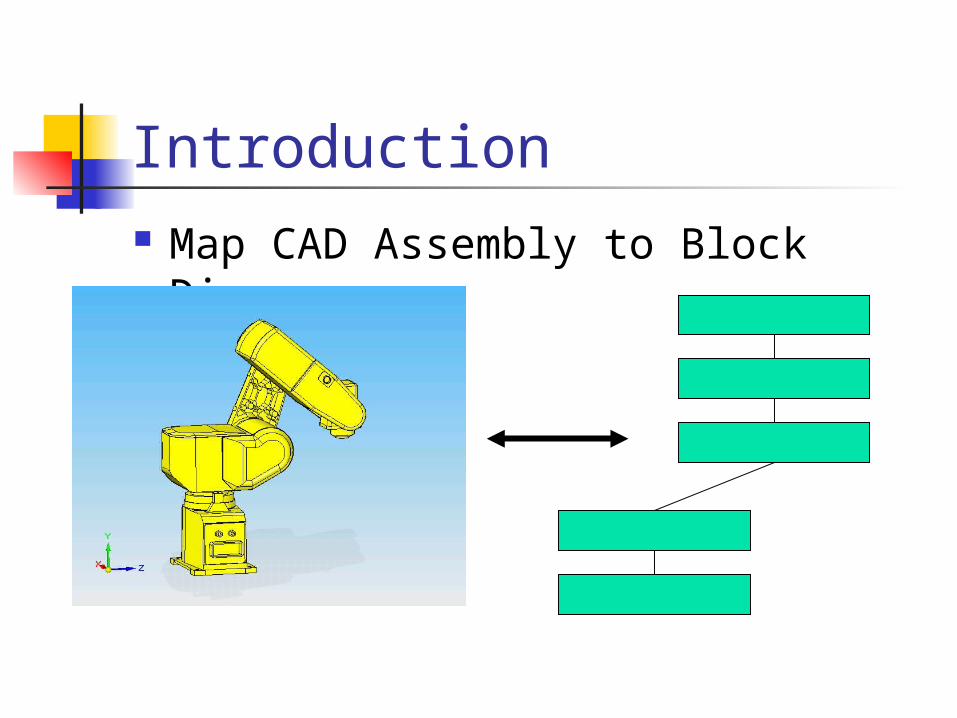
Introduction Map CAD Assembly to Block
Diagrams

Introduction Objectives
Provide simple mapping CAD BD Preserve mechanical/geometric
constraints Simulate mechanical behavior in BD
model; Ex. A CAD Model of Robot converted to
BD for simulation of robot dynamics
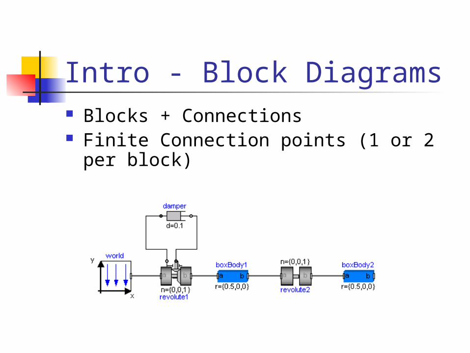
Intro - Block Diagrams Blocks + Connections Finite Connection points (1 or 2 per
block) Block Parameters Ex.
Intro - CAD Assembly Part and geometry Assemblies and geometric relations Example Geometric relations Infinite connection points

Intro - CAD Assembly Part and geometry
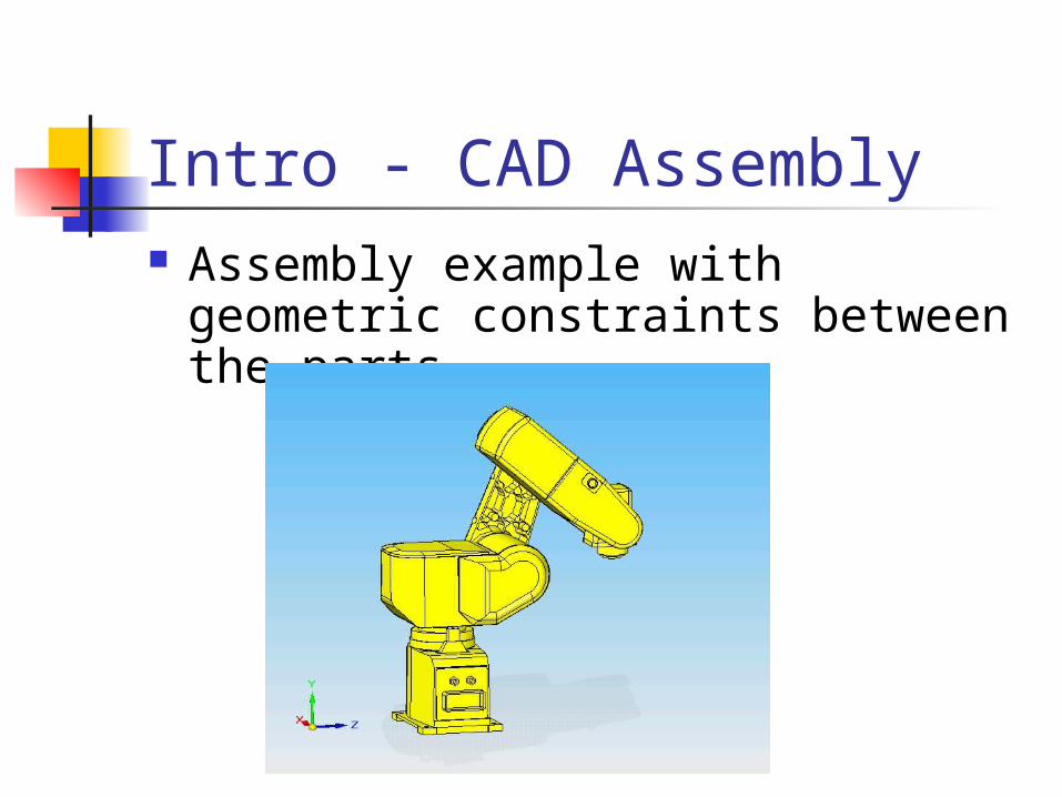
Intro - CAD Assembly Assembly example with geometric
constraints between the parts

Intro - CAD Assembly Ex #1: Planar Mate Geometric Relation
Before and after application
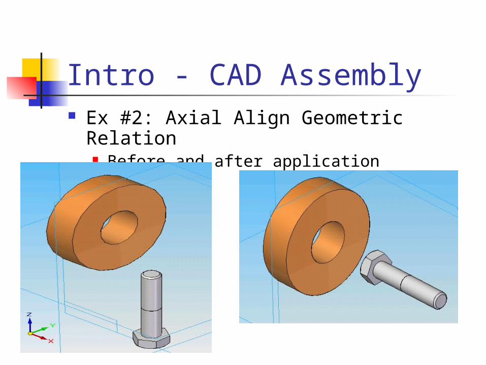
Intro - CAD Assembly Ex #2: Axial Align Geometric Relation
Before and after application
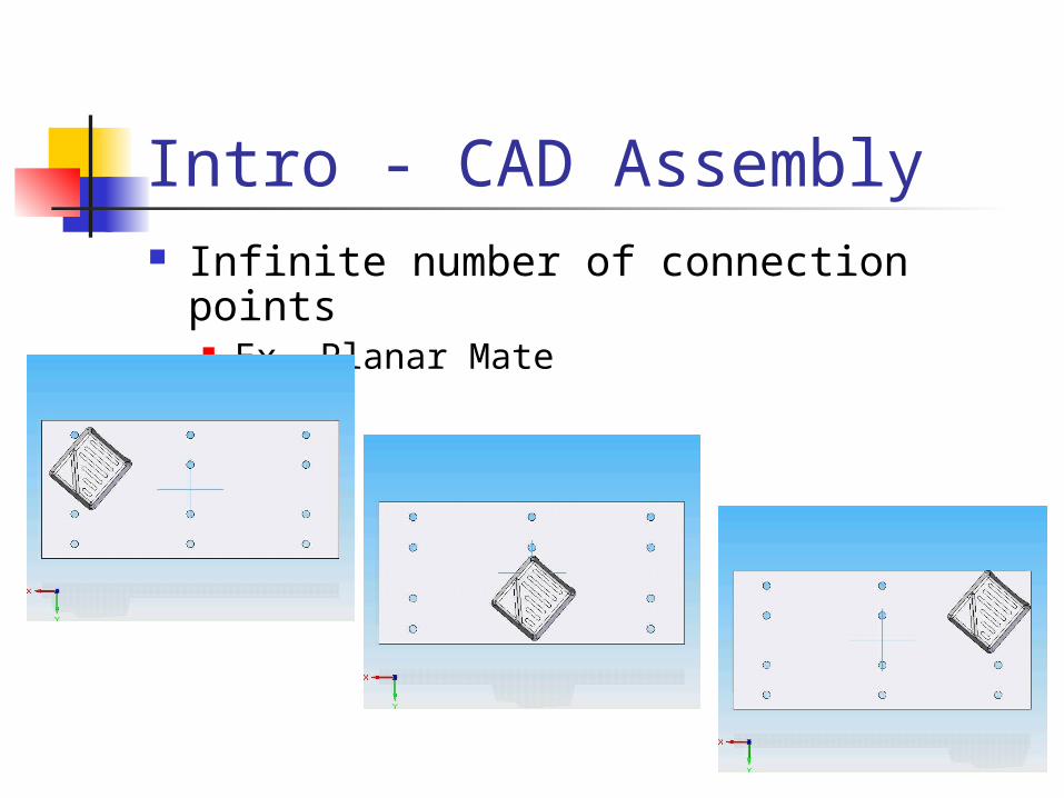
Intro - CAD Assembly Infinite number of connection points
Ex. Planar Mate
Comparison BD – CAD Block diagram is abstract CAD is geometry information rich
Block diagram provides finite connections
CAD geometry provides infinite connections points
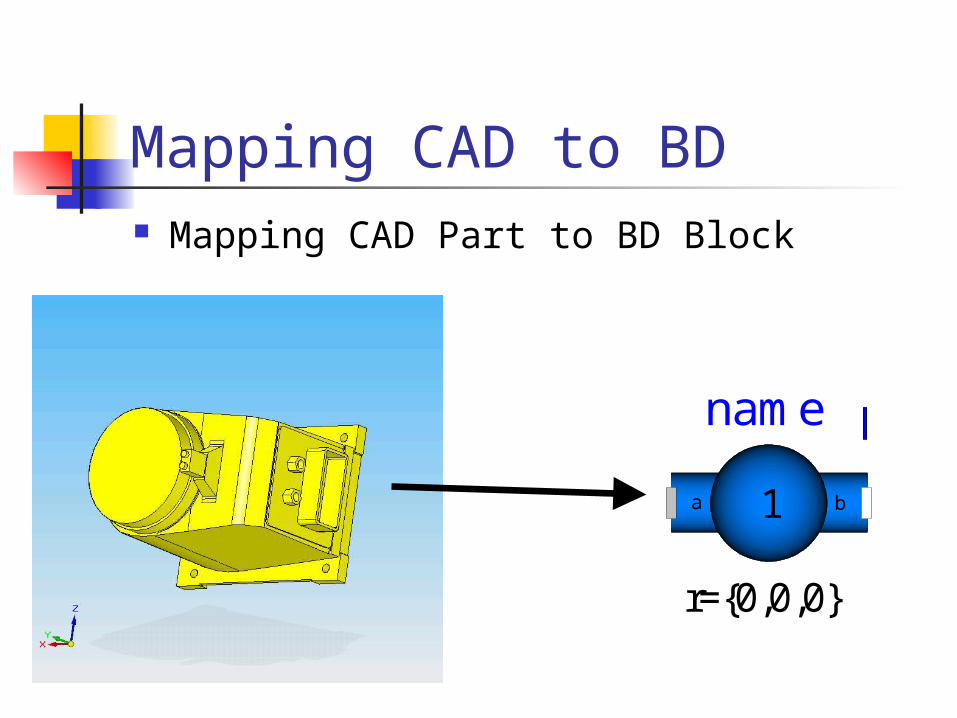
Mapping CAD to BD Mapping CAD Part to BD Block
name
r={0,0,0}
1 ba
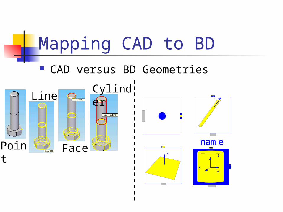
Mapping CAD to BD CAD versus BD Geometries
Z
XY
nameZ
FacePoint
LineCylinder
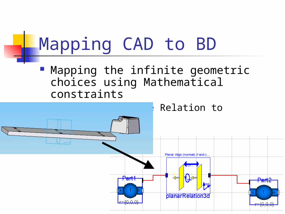
Mapping CAD to BD Mapping the infinite geometric choices
using Mathematical constraints Ex. Mapping Mate Relation to equations
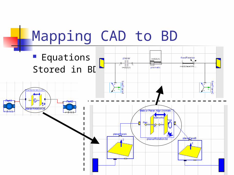
Mapping CAD to BD Equations Stored in BD
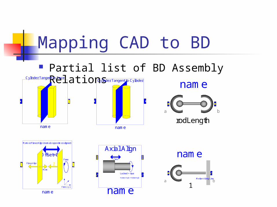
Mapping CAD to BD Partial list of BD Assembly Relations
name
Cylinder Tangent to Cylinder
name
Mate or Planar Align (normals opposite or aligned)
ZFree
Free x y z
Offset=0
Mate
Planar Align
Axial AlignFree
Locked = true
name
Rotation Angle = RotationAngle
name
rodLengtha b
name
Cylinder Tangent to Face
name
1a b
Motion Along Line
Automating the Process Convert CAD Assembly to BD assembly
automatically Extract CAD Part Geometry Information Extract CAD Assembly Information Example Conversion
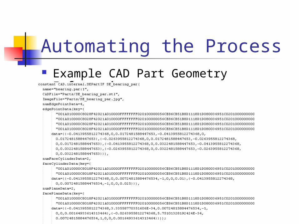
Automating the Process Example CAD Part Geometry
Information
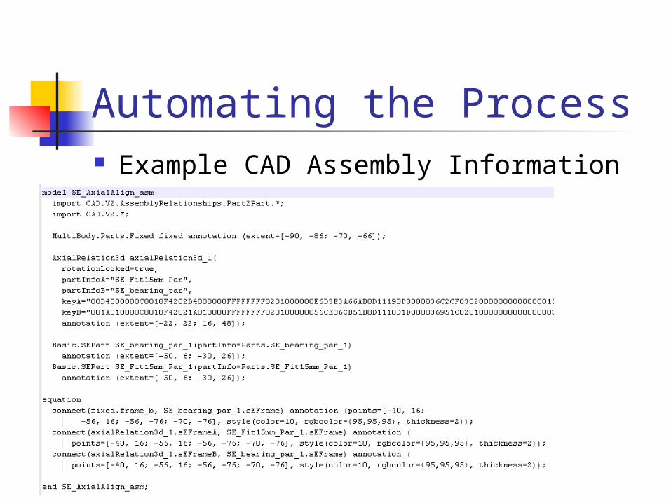
Automating the Process Example CAD Assembly Information
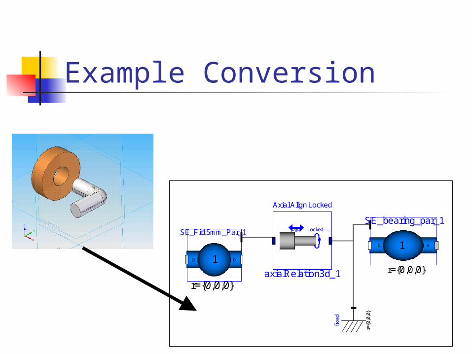
Example Conversion
fixed
r={0
,0,0
}
Axial Align Locked
Free Locked=...
axialRelation3d_1
SE_bearing_par_1
r={0,0,0}
1b a
SE_Fit15mm_Par_1
r={0,0,0}
1 ba
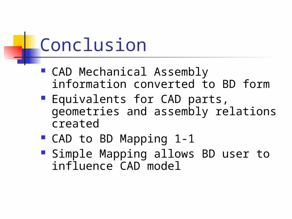
Conclusion CAD Mechanical Assembly information
converted to BD form Equivalents for CAD parts, geometries
and assembly relations created CAD to BD Mapping 1-1 Simple Mapping allows BD user to
influence CAD model
Future Work Complete bi-directional model
synchronization algorithm (BD->CAD, CAD->BD)
Demonstrate BD influence on CAD model development