representation of activity knowledge for project management
TRANSCRIPT

Rep resentation of Activity Knowledge for Project Management
Arvirid Sathi Mark S. Fox
Mike Grccnberg
CM U-RI-TR-85- 17
The Robotics Institute Carnegie-Mellon University
Pittsburgh, Pennsylvania 15213
September 1985
Copyright @ 1985 Carncgie-Mellon University
This research is supported by Digital Equipment Corporation. The vicws and conclusions contained in this documcnt are those of the author, and should not bc interpreted as representing the official policies, eithcr exprcsscd or implied, of Digital Equipment Corporation.
Appeared in IEEE Transactions on Paltern Analysis and Machine Intelligence PAMI-7, no. 5 (Septcmbcr 1985): 531-552.

i
Table of Contents 1. Introduction 2. A Project Management Example 3. Layers of Representation
3.1. The Domain Layer 3.2. The Semantic Layer 3.3. The Epistemological Layer 3.4. The Logical Layer 3.5. The Implementation Layer
4. The Theory of Activity, State and Goals 4.1. Theory of Activity 4.2. Theory of State
4.2.1. State Aggregation 4.2.2. State Abstraction
4.3. Goals 4.4. Instantiation and Manifestation
5.1. Theory of Time 5. Theory of Causality and Time
5.1 .l. Temporal Relations in State-tree 5.1 -2. Temporal Aggregation of Activities 5.1.3. Time Granularity
5.2. Theory of Causality 5.3. Time, Causality and Goals
6. Theory of Relational Abstraction 7. Conclusion
1 3 4 5 6 6
12 12 13 14 18 18 21 22 25 27 28 31 33 34 35 47 47 50

ii

iii
List of Figures Figure 1 : The set, the prototype and the individuals Figure 2: Activity aggregation and abstraction Figure 3: State classification hierarchy Figure 4: State aggregation for cpu-design Figure 5: Aggregation and abstraction of states Figure 6: Activity goals Figure 7: Activity hierarchy and individuation Figure 8: The temporal relations Figure 9: Temporal aggregation of status Figure 10: Temporal aggregation of possession Figure 1 1 : Complex temporal aggregation Figure 1 2: Causality and abstraction Figure 13: Propagation of causality I Figure 14: Propagation of causality II Figure 15: Causation: problems in transitivity Figure 16: Causation: state space approach Figure 17: Causation: multiple link alternative Figure 18: Activity clusters illustration Figu re 19: Causation: aggregations and cause-enable Figure 20: Status of goal
7 17 20 22 23 24 26 29 32 33 34 36 39 41 42 43 44 45 46 48


V
List of Schema 1 : The set schema Schema 2: The prototype schema Schema 3: The individual schema Schema 4: The prototype-of relation Schema 5: The is-a relation Schema 6: The subset-of relation Schema 7: The subset-of-inclusions Schema 8: The has-elaboration relation Schema 9: The elaboration-of relation
Schemata
Schema 10: Schema 11: Schema 12: Schema 13: Schema 14: Schema 15: Schema 16: Schema 17: Schema 18: Schema 19: Schema 20: Schema 21 : Schema 22: Schema 23: Schema 24: Schema 25: Schema 26: Schema 27: Schema 28: Schema 29: Schema 30: Schema 31 : Schema 32: Schema 33: Schema 34: Schema 35: Schema 36: Schema 37: Schema 30: Schema 39: Schema 40: Schema 41 : Schema 42: Schema 43: Schema 44:
The elaboration-of-inclusion The part-of relation The revision-of relation Instance schema Instance- inclusion spec Activity schema Cpu-engineering schema Activity schema Sub-activity-of relation Inclusions in sub-activity-of Has-sub-activity relation Aggregate activity schema Cpu-engineering-network schema Modified activity schema Cpu-design activity schema The sub-state-of relation Start-cpu-design schema Or-cpu-design schema Possess-C AD - mac h ine schema Or-state schema Start-design-cpu-network schema Goal-state schema Aggregate goal schema The must-satisfy relation Activity schema with cost goal Goal constraint Cpu-design%l schema Manifestation of cpu-design%l Before schema Illustration of time-line Illustration of time interval Sub-activity-of relation The enable relation Cause relation Or-state schema
Schema 45: And-state schema
7 7 7 7 9 9 9
10 10 10 11 11 12 12 13 13 15 16 16 16 17 17 19 19 20 21 21 21 22 22 24 24 24 25 25 26 27 30 30 30 33 37 37 38 38

vi
Schema 46: Status predicate schema Schema 47: Possess predicate schema Schema 48: The cause-enable relation Schema 49: The relation next-activity-of Schema 50: Sub-operation-of schema
38 38 46 49 50

Abstract
Representation of activity knowledge is important to any application which must reason about activities, such as new product management, factory scheduling, robot control, vehicle control, software engineering and air traffic control. This article provides an integration of the underlying theories needed for modeling activities. Using the domain of large computer design projects as example, the semantics of activity modeling is described. While past research in Knowledge Representation has discovered most of the underlying concepts, our attempt is towards their integration. This includes the epistemological concepts for erecting the required knowledge structure; the concepts of Activity, State, Goal and Manifestation for the adequate description of the plan and the progress; and the concepts of Time and Causality to infer the progression among the activities. We also address the issues which arise due to the integration of aggregation, time and causality among activities and states.

1
1. Introduction The management of activities in large projects is composed of four parts:
1. Planning: Definition of activities and specification of precedence, resource requirements, durations, due dates, and milestones.
2. Scheduling: Selection of activities to perform (if more than one way exists), and the assignment of actual times and resources.
3. Chronicling: Monitoring of project performance, detection of deviations from the schedule and the repair' of the original schedule (possibly resulting in renewed planning and scheduling).
4. Analysis: Evaluation of plans, schedules, and chronicled activities for normal reporting and the detection of extra-ordinary situations.
Central to the performance of these activities is the availability of a theory of activity representation. This theory would have to be comprised of two parts: syntactic conventions and a set of semantic primitives. It would have to satisfy three criteria:
1. Completeness: represents all relevant concepts. Given an application, completeness requires that the representation span the domain.
2. Precision: provides appropriate granularity of knowledge. The representation should be capable.of describing the domain situations at the level of precision used in the domain.
3. Clarity: lacks ambiguity in interpretation. While domain languages are typically ambiguous, the representation should provide clarity by insuring that each real situation corresponds to one and only one model.
The importance of such a theory is crucial not only to the construction of project management systems but to any application which must reason about activities. These include factory scheduling, robot control, vehicle control, software engineering and air traffic control. This article provides the basic elements of the theory needed for modeling activities, which can be used for the knowledge engineering in such planning, scheduling and/or progress chronicling tasks.
Considerable effort has gone into constructing pieces of such a theory, e.g., the aspects of time [l], causality [30], activity [2], authority [27], constraint representation [12] and ownership [21]. What is missing is a unification of these ideas into a single theory and a test of its adequacy.
Since 1982, the Callisto project [34] has been constructing such a theory in the context of engineering project management. The role of project management has increased in importance. Innovation is becoming crucial to the continued vitality of industry. New products and innovations to existing products are occurring with increasing rapidity while product lives decrease. In an effort to
'Repair or debugging involves three activities: information collection/management, analysis, and replanning/rescheduling. Chronicling stands for the information collection and management aspects of repair, while analysis, planning and scheduling are covered elsewhere.

2
maintain market share, companies are forced to reduce product development time. By entering the market as early as possible, the product life may be extended. Product development time may be reduced by product simplification or through better management of the development activities. Our focus is the latter.
Experience has shown that project management has become more difficult, especially in the high- technology industries. A close observation of project activities shows that errors and inefficiencies increase as the size of the project grows. The successful performance of project tasks are hindered by:
Complexity: due to the number and degree of interactions among activities. For example, in a computer design project, a design engineer’s decision to use one particular integrated circuit may affect the supply of parts and production of prototypes by the manufacturing people.
Uncertainty: of direction due to the unknown state of other activities and the environment. For example, the gate-level design of a board may proceed for a while and then be disrupted by the unavailability of a chip or newly found bottlenecks in the module level design.
Change: in activities to be performed and products to be produced, requiring project flexibility and adaptability. Due to technological nature of the engineering design activities, a large number of activities are changed along the learning curve. Often, a plan is generated in the beginning only as a guide for the future planning.
Algorithms exist which address part of the project management problem. PERT[24] and CPM [20,23] address the scheduling problem, in particular the detection of critical paths. Other techniques exist for the smooth assignment of resources [41]. On the other hand few, if any, systems have addressed the problem of observing and analyzing the execution of activities, understanding how they affect other activities and managing these effects. These are some of the issues which Callisto has addressed.
In addition to activity management, Callisto provides support to:
Product Management: main!aining a current description of the product (which is usually the outcome of a project), and determining the effects of changes to its definition (e.g., engineering change orders).
Resource Management: acquisition, storage, and assignment of the many resources required to support a project.
The purpose of this paper is to describe the theory of activity representation embodied in Callisto. Only a portion of this theory is described, that is, the representation of state, activity, abstraction, aggregation, time and causality. Due to limitations in size, the representation of authority, responsibility and possession are not included but can be found in Sathi and Fox [%I.
The paper begins with an example from project management. Next, the foundation on which the theory is built, is described. This foundation is a layered representation based upon the view

3
described by Brachman [5]. The two main parts of the theory are then described: representation of states, activities and goals; and the representation of time and causality. Finally, we provide a discussion of the relational abstraction.
2. A Project Management Example Let us use an example to explain the issues involved in the semantics of project representation. Following is a typical description of a project :
The engineering development activity for a cpu typically involves the development of specifications, design on a CAD tool (the CAD tool is owned by the manufacturing department which uses only a portion of its capacity. The rest is used for other users and preventive maintenance. In an earlier agreement, the manufacturing department promised to give 60% of the CAD tool's use to the engineering department for designing Micro-84), and verification of the board on test cases. A committee of hardware engineers develops the specifications and assigns an engineer to design and verify the board specifications. Hence, specification is followed by design, and verification. If verification is successful, the cpu is released for prototype development. Otherwise, the bug is located, the board is revised, sild the design is performed again.
Mr. Jones, a project manager in the engineering department has been assigned ilie responsibility of designing the Micro-84 CPU board. As it is not poscible to ccver all design aspects together, two milestones l ime been sci for. clcudOp!rl;. versiuir 1 and 2 of the board respwlively, and it is expecled that tho version 2 of the board will conform to the project goals.
The expected duration for the design activities depends heavily on whether a new technology is used for the design or not. As t h e decision on whether to go with t he new technology has not yet been made, two schedules need to be developed, one with the assumption that the design durations will be reduced with the help of MCA's and the other without the MCA technology.
For !ho dcsign cf ?he Micrc-84 CPU, a seqssnce r?f activities is described ~ i t h their lngical relationships, the product change process, and resources required. Itemized below are the types of knowledge required for scheduling or tracking the progress of these activities.
0 Required activities.
0 Durations for each activity.
0 Activity precedence.
e How activities are aggregated and abstracted.
a Conditions under which activities can be performed, e.g., isr,-,poral relationship between specification and design (what if they overlap).

4
0 Logical connections among activities, e.g., design is done i f specification is completed or i f verification fails.
0 Individualization of schedules for the two versions of the board, from a prototypical sc hed u le.
0 Representation of the two alternate schedules and actual dates for starting and finishing activities, and for goals and milestones.
0 Representation of changes in the product, or changes in the start or end dates (e.g., what happens when it is decided that MCA's are to be used for some portions and hence durations need to be modified to an in-between level).
0 Resources required for each of these activities: engineers, CAD tool, simulation software and test examples.
0 The period of time during which the above resources are required.
0 Representation of constraints, that restrict the usage of the resources, e.g., the maintenance schedule and previous reservations by other users on the CAD machine, and the use of engineers for the next project.
0 Interactions with the user (e.g., could he use his own terms instead of what we generate here).
3. Layers of Representation Given the above description, we now need to define the project concepts in terms of their attributes and relations. We need to define the engineering activities, their precedence and resource constraints as well as aggregations, computer part descriptions, resource descriptions, ownership, authority for resolving conflicts, and so on. For each of these, the model should define their attributes, relations, and the information that flows between these concepts based on their relationships. For example, if a computer part is designed by an engineer, so are its components.
It is natural to look for commonalities among these concepts and linkages. For example, if the aggregation of activities is in any way similsr to the asgregation of compute: components, then a common relation can be constructed to define the common definition of aggregation, which can be specialized for the two applications. We should be able to represent the domain dependent concepts in terms of more worldly domain independent ones, e.g., the concepts of time and causality for defining precedence constraints. In this way, we can capture the underlying meaning and semantics of relations and the related flow of information. Consequently, the meaning of such models can be enhanced by combining the individual concepts to form complex concepts. We also need an implementation language for representing these concepts, their linkages and the information flow across these relations.
The idea of a semantic representation of human knowledge originated in Quillian's thesis [29] in which concepts are represented by networks. A distinguishing feature of this work was the introduction of an "is-a" link which defines taxonomic relations and the inheritance of attributes from
5
super-concepts to sub-concepts in the hierarchy. The concept of semantic networks evolved [37,43] and has been implemented in languages such as KLONE [4], NETL [9], and [16]. In 1975, Minsky introduced the concept of "frame." A frame partitions a semantic network into easily identifiable concepts. A variety of frame languages have been created including FRL 1311, Concepts [22], KRL [3], UNITS [39] and SRL [ l l , 441. A number of researchers have contributed to the semantic network approach to organizing knowledge.' Contributions from Brachman [5]and Fox [12] have led to the definition of five layers of representation:
e The domain layer provides concepts, words and expressions specific to a domain of application.
0 The semantic layer is comprised of models of the common primitives such as the concepts of time, activity, state, agent, ownership, etc. These concepts are common across domains and can, therefore, be used as building blocks for modeling the domain specific concepts.
0 The epistemological layer provides a way of regulating the flow of information through inheritance (described in detail later in this section). This layer uses the concepts of set, prototype, levels of aggregation and the structural relations which link these concept. It captures the structural similarities across various concepts in the conceptual layer.
0 The logical layer defines the word concept as a collection of assertions (described in detail later in this section).
The implementation layer provides primitives for rnachine interpretation of the concepts arid the assertions.
Having provided an intuitive understanding of why each of these layers is needed, we will now describe these layers in detail. SRL 1441 is the representation language used through out this paper. We start with the implementation layer and define, as we go along, building blocks used in the subsequent layers.
3.1. The Domain layer For the project management example (section 2), we need to define the concepts of specification, design ar;d verificn:ion activitiss, and their :cl,?,?icnships, the computer parts, !he engincering and manufacturing departments, and the contracts between them on the usage of the CAD machine. These terms can now be defined much more easily using the epistemological concepts and the semantic definition of activities, objects and agents. The addition of a new domain only requires the addition of domain specific concepts and ?heir definition in terms of the epistemological and semantic layers.
*For a good review of the previous work, please refer to Urachnian [5].

6
3.2. The Semantic Layer The semantic layer contributes to the depth of representation by facilitating inheritance of the underlying common knowledge. For example, all types of activities, whether design or verification, engineering or manufacturing, share common information such as cost, duration, and responsibility. They have similar underlying notions of causality, time relationships, resource possessions and milestones. We, therefore, need a common definition of activity, which can be used for further defining specific activities.
The concepts in the semantic layer can be classified into three major categories: action related, object related and agent related. The action related primitives include concepts of activity, state, causation and temporal relations. The definition of object includes its refinements and disaggregations, and the theory of change. Constraints can be imposed on the definition of action or object related primitives. The agents possess and own objects and are organized through authority structures.
In the following sections, we will describe, in detail, the definition and representation for activity, state, time and causality. We will build a theory for each of these concepts, which brings forth a general definition of the concept. The semantic layer is defined using the concepts of inheritance and structure defined in the epistemological layer.
3.3. The Epistemological Layer The epistemological layer distinguishes types of slots and schemata. Prctotype, Individual, and Set are distinguished schema types. Structural and taxonomic relations (e.g., i s -a) are distinguished slots. Schemata are defined at this level with an active interpretation, e.g., slots and valiies may be inherited from one schema to another over a taxonomic relation, concepts and their relationships.
Set, Individual and Prototype A set is a concept defined as a collection of things that belong or are used together [42]; an individual is a a member of the s e t . The concept set describes the group characteristics of the individuals in the set (Le., statistics such as number, average, etc.). A prototype is a concept which describes the standard or typical features of the members of a set. Thus, the concept prototype contains the prototypical characteristics of the individuals, while the individuals contain their individual ctiaracteristics (either excepiioiis to the prototypical characteristics or individiinl identifiers). Figure 'I depicts the relationship among the set, the prototype and the members of the set. The relations member-of and has-member provide an aggregation of individuals to form sets and are thus similar to the aggregation mechanisms defined later in this section. The relation prototype-of links a prototype to a s e t . The relations is-a and instance are described later in this sect ion.

7
I- d
Figure 1 : The set, the prototype and the individuals
{{set IS-A: concept
HAS-MEMBER:}} HAS-PROTOTY PE:
Schema 1 : The set schema
{{PrototYPe IS-A: concept PROTOTY PE-OF:}}
Schema 2: The prototype schema
{{individual Is-A: concept
MEMBER. OF:}} INSTANCE:
Schema 3: The individual schema
{{prototype-of IS-A: relation INVERSE: has-prototype}}
Schema 4: The prototype-of relation
8
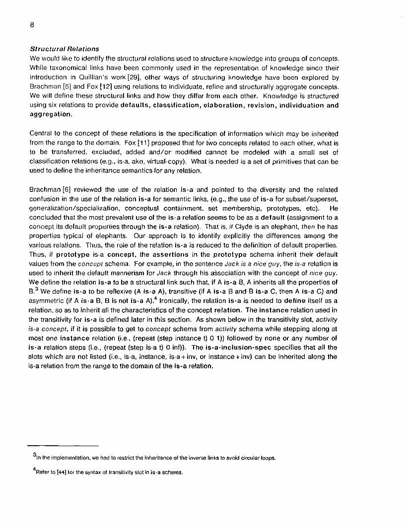
Structural Relations We would like to identify the structural relations used to structure knowledge into groups of concepts. While taxonomical links have been commonly used in the representation of knowledge since their introduction in Quillian’s work [29], other ways of structuring knowledge have been explored by Brachman [5] and Fox [12] using relations to individuate, refine and structurally aggregate concepts. We will define these structural links and how they differ from each other. Knowledge is structured using six relations to provide defaults, classification, elaboration, revision, individuation and aggregation.
Central to the concept of these relations is the specification of information which may be inherited from the range to the domain. Fox Ell] proposed that for two concepts related to each other, what is to be transferred, excluded, added and/or. modified cannot be modeled with a small set of classification relations (e.g., is-a, ako, virtual-copy). What is needed is a set of primitives that can be used to define the inheritance semantics for any relation.
Brachman [6] reviewed the use of the relation is-a and pointed to the diversity and the related confusion in the use of the relation is-a for semantic links, (e.g., the use of is-a for subset/superset, generalization/specialization, conceptual containment, set membership, prototypes, etc). He concluded that the most prevalent use of the is-a relation seems to be as a default (assignment to a concept its default properties through the is-a relation). That is, if Clyde is an elephant, then he has properties typical of elephants. Our approach is to identify explicitly the differences among the various relations. Thus, the role of the relation is-a is reduced to the definition of default properties. Thus, if prototype is-a concept, the assertions in the prototype schema inherit their default values from the concept schema. For example, in the senteiice Jack is a nice guy, the is-a relation is used to inherit the default mannerism for Jack through his association with the concept of nice guy. We define the relation is-a to be a structural link such that, i f A is-a B, A inherits all the properties of
We define is-a to be reflexive (A is-a A), transitive (if A is-a B and B is-a C, then A is-a C) and asymmetric (if A is-a 6, B is not is-a A).4 Ironically, the relation is-a is needed to define itself as a relation, so as to inherit all the characteristics of the concept relation. The instance relation used in the transitivity for is-a is defined later in this section. As shown below in the transitivity slot, activity is-a concept, i f it is possible to get to concept schema from activity schema while stepping along at most one instance relation (i.e., (repeat (step instance t) 0 1)) followed by none or any number of is-a relation steps (Le., (repeat (step is-a t) 0 inf)). The is-a-inclusion-spec specifies that all the slots which are not listed (Le., is-a, instance, is-a + inv, or instance + inv) can be inherited along the is-a relation from the range to the domain of the is-a relation.
In the implementation, we had to restrict the inheritance of the inverse links to avoid circular loops. a
4Refer to [44] for the syntax of transitivity slot in is-a schema.

9
{{is-a IS-A: relation IN c L u s I ON: is- a- incl usion -spec
(list (repeat (step instance t) 0 1) (repeat (step is-a t) 0 inf))
COMMENT: "is-a defines default")}
TRANSITIVITY:
{{ is-a-inclusion-spec INSTANCE: inClUSiOn-SpeC SLOT- RESTRICTION:
(not (or is-a instance is-a+ inv instance + inv))}} Schema 5: The is-a relation
Classification (defined in Webster's dictionary as a systematic arrangement in groups or categories according to established criteria) is the process by which a set is divided or partitioned into sub-sets on the basis of some attribute value. It is important to note that both the domain and the range of a classification are sets. For example, manufacturing activity is a su bset-of activity (classified on the basis of being an activity in the manufacturing domain. In the inverse process, specific sets can be combined to form more generic sets. We will use has-subset to relate a set (domain) to its sub-sets (range). The inverse of has-subset is subset-of. We will see later how this process is different in its inheritance semantics from aggregation and revision processes. In terms of inheritance semantics, su bset-of-include shows the information that can be inherited across the subset-of relation (i.e., all slots except for subset-of and prctotype-of arid all the values). The relation su bset-of is transitive, asymmetric and non-refle~ive.~
{{su bset-of IS-A: relation INVERSE: has-subset DOMAIN: (type is-a Set) RANGE: (schema (type is-a set)) INCLUSION: subset-of-incl TRANSITIVITY: (repeat (step subsei-of t) 1 inf) COMMENT: "subset-of defines classification"}}
Schema 6: The subset-of relation
{{su bset-of- incl INSTANCE: inClUSiOn-SpeC SLOT.RESTRICTION: (not (Or subset-of
VALUE-RESTRICTION: t)} has-prototype))
Schema 7: The subset-of-inclusions
5As defined in the transitivity slot, manulacturing-activify is subset-ol activity if it is possible to get to the activity schema from the manufacluring-activity schema while stepping along at least one (1 to infinity) su bset-of relation.

10
The process of elaboration (which means to expand something in detail) takes a concept and fills in details. Details can be appended by adding assertions (e.g., slots with values) to a concept. While classification relations operate on sets, the elaboration relation operates on individuals and prototypes. In our model has-elaboration takes an individual or prototype as domain and another individual or prototype as range. The inverse of elaboration is abstraction, which according to Webster's dictionary is the process of reducing specific information, and is represented by the relation elaboration-of. Both elaboration-of and has-elaboration are transitive, asymmetric and reflexive.' The ela boration-of-inclusion schema defines the information that is inherited along the elaboration-of relation (Le.! all the slots except for elaboration-of and all the values).
{{has-elaboration IS-A: relation DOMAIN: (or (type is-a individual)
RANGE: (schema (or (type is-a individual)
INVERSE: elaboration-of TRANSITIVITY: (repeat (step has-elaboration t) 0 inf)}}
(type is-a prototype))
(type is-a prototype)))
Schema 8: The has-elaboration relation
{(cla boration-of IS-A: relation DOMAIN: (or (type is-a individual)
RANGE: (schenia (or (type is-a individual)
INVERSE: has-elaboration INCLUSION: elaboration-of-inclusion TRANSITIVITY: (repeat (step elzboration-of t) 0 inf) COMMENT: "elaboration-of defines abstraction"}}
(type is-a prototype))
(tjlpe is-a prototype)))
Schema 9: The elaboration-of relation
{{era boration-of-inclusion INSTANCE: inClUSiOn-SpeC
VALUE - REST R I CT I 0 N : t } } SLOT-RESTRICTION: (not elaboration-of)
Schema 10: The elaboration-of-inclusion
The emphasis in aggregation (i.e., to collect or gather into a whole) is towards combining the parts to make a whole. The parts could belong to different sets, or instances of sets. The disaggregates are pa rt-of the aggregate concept. Parts inherit some attributes from their aggregation (e.g., ownership), others are aggregated (e.g., cost), or averaged (e.g., performance). For example, cpu-specification is part-of the cpu-engineering-network. The inverse of part-of is has-part. The part-of relation is reflexive as well as transitive though asymmetric (similar to the elaboration-of relation, described above).
6As defined in the transitivity slot, Micro-84-version-1 is elaboration-of Micro-84 if it is possible to get to the Micro-84-version- 1 schema from the Micro-84 schema while stepping along zero or more (0 to infinity) elaboration-of relations.

11
{(pa rt-of IS-A: relation DOMAIN: (or (type is-a individual)
RANGE: (schema (or (type is-a individual)
TRANSITIVITY: (repeat (step part-of t) 0 inf) COMMENT: "part-of defines aggregation"}}
(type is-a prototype))
(type is-a prototype))) INVERSE: has-part
Schema 11 : The part-of relation
Thus the process of revision (Le., to make a newly amended, improved, or up-fo-date version) converts a range object into a domain object by adding improvements in its representation. Here, both the range and the domain need to be at the same level of aggregation and belong to the same set of concepts for a meaningful revision. Revisions can be introduced by adding or transforming slots. For example, Version 2 of Micro-84 is a revision-of version 7. Both version 1 and 2 are at the same level of aggregation. As opposed to elaboration, revision is a transformation process, and thus describes a progression in time. The inverse link is revised-by and it does not conceptually represent a process. The relation revision-of is transitive, asymmetric and non reflexive (similar to the su bset-of relation).
{{ revision-of !SA: relation DOMAIN: (or (type is-a prototype)
RANGE: (schema (or (type is-a prototype) (type is-a individual))
(type is-a individual)))
(repeat (step revision-of t) 1 inf)}}
INVERSE: revised-by TRANSITIVITY:
Schema 12: The revision-of relation
Individuation is the development of the individual from the universal [5] and is represented by the instance relation. It can be interpreted as a copy of the prototype with an individual name and exceptions, i f any. For example, cpu-engineering is the process of engineering development of a cpu, while cpu-engineering% 7 is an instance of cpu-engineering for building the first version of Micro-84 cpu.

12
{{instance IS-A: relation DOMAIN: (type is-a individual) RANGE: (schema (type is-a prototype)) INCLUSION: instance-inclusion}}
Schema 13: Instance schema
{{ instance-inclusion INSTANCE: inClUSiOn-SpeC SLOT-RESTRICTION: (not (or prototype-of subset-of is-a
is-a + inv instance + inv)) VALUE-RESTRICTION: t}}
Schema 14: Instance-inclusion spec
As we go on to develop relations for specialized needs, we find that these relations can inherit the inheritance semantics from more generic relations. For example, if the aggregation process in objects is similar to the aggregation process in activities, then their commonalities can be represented using a domain independent part-of relation, from which each of the relations, specific to activities and objects, inherits the common inheritance semantics and adds to it what is specific to activities or objects. Thus, we begin to build a hierarchy of these relations, starting from the most general concepts like classification and abstraction, to more and more specific relations. Such relations (e.g., su b-activity-of and sub-state-of, in sections 4.1 and 4.2, respectively) were defined in the semantic layer.
3.4. The Logical Layer The logical layer provides a logical interpretation of the information stored in the schemata. In particular, a schema-slot-value triplet is interpreted as an assertion possessed by the schema (Le., the attribute named by the slot with the defined value). For example, "the project cpu-engineering costs $20,000" is an assertion. Assertions are grouped together (in a schema) to define a single concept.
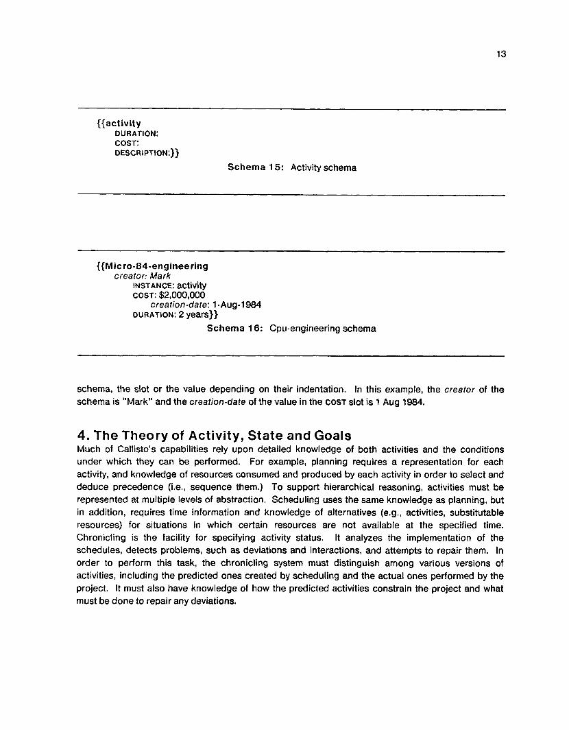
3.5. The Implementation Layer The purpose of the implementation layer is to define the lowest level data structures. The most basic representation primitive is a schema. Physically, a schema is composed of a schema name (printed in bold font) and a set of slots (printed in small caps). A schema is always enclosed by double braces with the schema name appearing at the top. The slots can have values assigned to them.
For example, the activity schema is composed of a number of slots defining attributes of the activity such as duration, cost and description. The Micro-84-engineering schema defines values for each of the slots defined in the activity schema, e.g., cost of $2,000,000 and duration of 2 years.
Meta-information may be attached to any part of a schema. It provides the user with a means of documenting the information in a schema, and also for defining the semantics of schema, slots and values. In the cpu-engineering schema, the slots in italics are meta-information attached to the
13
{{activity DURATION: COST: DESCRIPTION:}}
Schema 15: Activity schema
{{Mic ro-84-enginee ring creator: Mark
INSTANCE: activity COST: $2,000,000
creation-date: 1 -Aug-1984 DURATION: 2 years}}
Schema 16: Cpu-engineering schema
schema, the slot or the value depending on their indentation. In this example, the creator of the schema is "Mark" and the creation-dare of the value in the COST slot is 1 Aug 1984.
4. The Theory of Activity, State and Goals Much of Callisto's capabilities rely upon detailed knowledge of both activities and the conditions under which they can be performed. For example, planning requires a representation for each activity, and knowledge of resources consumed and produced by each activity in order to select and deduce precedence (i.e., sequence them.) To support hierarchical reasoning, activities must be represented at multiple levels of abstraction. Scheduling uses the same knowledge as planning, but in addition, requires time information and knowledge of alternatives (e.g., activities, substitutable resources) for situations in which certain resources are not available at the specified time. Chronicling is the facility for specifying activity status. It analyzes the implementation of the schedules, detects problems, such as deviations and interactions, and attempts to repair them. In order to perform this task, the chronicling system must distinguish among various versions of activities, including the predicted ones created by scheduling and the actual ones performed by the project. It must also have knowledge of how the predicted activities constrain the project and what must be done to repair any deviations.

14
4.1. Theory of Activity First, we need to define the concept of activity. This definition should include the type of tasks that can be called activities, relationships among them and with project goals, and issues of aggregation and abstraction. Consider the example:
... a project manager has been assigned the responsibility of designing the Micro-84 CPU Board. This design involves development of specifications, design on a CAD tool, and verification of the board on test cases.
Are all of these activities? How is the overall project related to these activities? How are the goals set? Finally, how is their disaggregation done by the project manager, and by others in the organization?
Considerable research work has been done in defining and relating activities or acts in natural language systems, problem solving systems, and in linguistics and phi l~sophy.~ These works provide useful insights into the hierarchical representation of activities, and in representing the prerequisites and results of an activity. Allen [2] has developed a theory of action, which is by far the most general and includes actions involving non-activity, actions which are not easily decomposable and actions which occur simultaneously.
We define the activity as the basic unit of action in the project management environment. The project manager starts with a project activity' assigned to him, disaggregates the project into a set of sub-activities, the execution or completion of which leads to the completion of the project. An Activity is a transformation of the world from one situation or state to another [25], which, directly or indirectly, carries the project from the starting state towards the goal state.
Aggregation and Abstraction Activities are often defined at many levels of abstraction. Sacerdoti [32, 331 constructed a system which stratified activities by the removal of conditions. The choice of condition was based on "importance." In the NONLIN system, Tate [40] developed a task formalism, which described various actions, pre-conditions and precedences. The NONLIN system expanded these high level descriptions into detailed plans. In the task formalism, the supervised conditions were differentiated from others as they involved details that could be expanded by the planning system (and, thus, involved no interaction with the other high level activities). In order to facilitate different levels of aggregation, Goldstein and Roberts [13] used su b-activity-of, which provides disaggregation of activities. The relation refined-by was used by Ellis [8] and Fox [12] to connect activities to their detailed counterparts.
We use the epistemological layer concepts to model the relationship between cpu-engineering and its components, the cpu-specification, cpu-design and cpu-verification activities. None of the relations, mentioned by the researchers above, seem appropriate for relating cpu-engineering to cpu-specification. It is not just an elaboration, because elaboration involves an expansion of an object into another, where both are at the same level of aggregation. It is not a disaggregation (as
7 ~ 0 r an excellent review, please refer to [21.
8A project activity in the engineering design context starts with a plan to produce a new product and ends with the first revenue shipment of the product. It has a goal to design the product, while the starting point is an abstract concept in the mind of the design initiator.

15
implicitly stated in the su b-activity-of relation of Goldstein), because cpu-engineering is not at the same level of detail (or abstraction) as cpu-specification. In other words, the different levels of specificity [32,40] and and/or aggregation [17] coexist in the specification of activities.
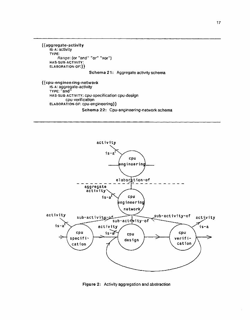
Thus, we should be using both aggregation and elaboration. An activity is elaborated to an aggregate activity (an activity network), which then has activities that are part-of the aggregate activity. For example, the cpu-engineering activity has an elaboration, cpu-engineering-network, which in turn, has three activities cpu-specification, cpu-design and cpu-verification as pa rt-of cpu-engineering-network. The eta boration-of relation helps in the separation of the single activity, cpu-engineering, from its detailed description, thus facilitating descriptions at different levels of abstraction or multiple elaborations of the same activity. For example, as in Tate [40], the activity cpu-engineering describes all the interactions with the other activities (outside the cpu-enginnering-network), while the interactions within the cpu-engineering-network are hidden at the level of the high level activity, cpu-engineering (see figure 2 and section 4.2).
We will discuss inheritance issues related to activity aggregation next, and issues related to temporal aggregation in section 5.1. The SRL representation of the concept activity is as follows :
{{activity ELAEORATION-OF:
Range: (schema (type is-a activity))
Range: (schema (type is-a activity))
Range: (schema (type is-a activity))
HAS-ELABORATION:
PART- OF:
COST: DURATION:}}
Schema 17: Activity schema
An activity should inherit information from other activities in higher and lower levels of abstraction. For example, if the activity cpu-engineering is the responsibility of a project manager, he is also responsible for cpu-sbecification, cpu-design and cpu-verification activities. Also, the cost of executing cpu-engineering should be the aggregation of the cost of its lower level activities. As these various types of inheritances are speci!ic !o the activi?y world. it is inappropriate to include them in the definition of the part-of relation. We define the sub-activity-of relation, which acts like part-of, for aggregating activities. Its inverse is the relation has-su b-activity.
There are two types of information flow across the aggregation levels. First, is the inheritance of information by lower level activities from the higher levels. Inheritance flows from the range to the domain via the sub-activity-of relation and the inclusion specifications in SRL. Second, the higher level activities aggregate information (e.g., cost) from lower levels (through a many-to-one map specification, has-sub-a~tivity-map).~ This aggregation of information can be represented in the su b-activity-of relation:
'We will later return to aggregation (of activity status), while describing the representation of state.

16
{ { su b- ac t ivit y -of IS-A: part-of
INCLUSION: sub-activity-of-incl
Range: (type is-a activity)
Range: (type is-a activity)}}
INVERSE: has-sub-activity
DOhl A IN:
RANGE:
Schema 18: Sub-activity-of relation
({su b-activity-of-incl IS-A inclusion-spec SLOT- REsTRIcTIoN:(or priority responsibility-of)}}
Schema 19: Inclusions in sub-activity-of
{{ has-su b-activity SA: has-part MA P : has-su b- acti vi ty- map}}
Schema 20: Has-sub-activity relation
Here, has-su b-activity-map defines what can be aggregated along the has-sub-activity relation, while sub-activity-of-incl defines the information that can be inherited along the su b-activity-of relation. The schema description of su b-activity-of-incl states that the slots "priority" and "responsibility-of" can be inherited by a sub-activity, from its super-activity.
The has-elaboration relations can be used to link an abstract activity to a detailed activity network. These relations are useful in multi-user communication situations where an activity at one level of description needs to be elaborated into its components at a lower level. For example, the engineering manager thinks of cpu-engineering as a single activity with no further disaggregations. The same activity is an aggregate activity further decomposed into cpu-specification, cpu-design and cpu-verification activities in the eyes of the project manager dealing with these activities. The relation ela boration-of, which relates a detailed aggregate activity (cpu-engineering-network) to the abstract activity (cpu-engineering), suffices in its inheritance definition as it inherits all information from the abstract to the elaborated concept (figure 2).
How are the activities aggregated? It is not necessary for the aggregation to be conjunctive only. In real life, very often managers refer to disjunct aggregations (The design can be done either by design on CAD machine or on the bread-board). The aggregate activity, therefore, could be a conjunctive or disjunctive aggregation of its components. The schema for aggregate activity contains a type slot to provide this information :
17
{ { agg regate-ac tivity IS-A: activity TYPE:
Range: (or "and" "or" "xor") HAS-SUB-ACTIVITY: ELABORATION-OF:}}
Schema 21 : Aggregate activity schema
{{cpu-engineering-network IS-A: aggregate-activity TYPE: "and" HAS-SUB-ACTIVITY: cpu-specification cpu-design
ELABORATION-OF: cpu-engineering}} cpu-verification
Schema 22: Cpu-engineering-network schema
a c t i v i t y
i s - a
aggregate a c t i v i t y
i s-a
ac t
Figure 2: Activity aggregation and abstraction

18
Is it necessary for an activity to be part of one and only one aggregate activity? While the project manager considers cpu-specification, cpu-design and cpu-verification as parts of a project, a design engineer would probably consider the cpu-design as a part of various design activities to be done. In the organizational environment, it is common to find that quality control and the material departments aggregate activities in different ways. Similarly, there can be multiple elaborations of the same activity, each emphasizing different aspects of the activity. For example, the overall activity cpu-engineering may have altogether different components for the CAD and physical space designers, respectively. Each of these elaborations refers to the same abstract activity. As specified, the activity representation is capable of dealing with multiple ways of aggregation and elaboration.
4.2. Theory of State The next problem to be settled is the representation of conditions under which an activity may be performed, and the new conditions produced by the activity. In our example, cpu-design activity is started when cpu-specification is completed or if cpu-verification fails. In the project management tasks, such arbitrarily complex conditions involving logical constructs should be represented by the activity model.
Let LIS start with the definition of a state. Hendrix [15] described a state of the world model, "like a still photograph of a dynamic situation, representing objects and the relationships among objects as they exist the moment the photograph is taken." In project management, we found that the concept of state (or event as used in PERTICPM models [20, 231 was even more general and included state of beings over time (similar to the definition of situation in Hendrix [17]). Thus, state defines a fact which holds as of some point in time (e.g., cpu-specification is complete) or for a period of time (e.g., possession of CAD machine for the duration of cpu-design)."
4.2.1. State Aggregation In the world of project activities, we would like to use states as a way of representing alternative scenarios or situations in which an activity can be executed, as well as the resulting alternative outcomes. Thus, using superimposed logical structures [17], different scenarios required for executing the activity are combined to form a composite state, which enables the activity. The overall logical structure holds whenever any of its constituent alternative situations holds. We, therefore, have a relative representation of the type "if ... then start the activity." For example, cpu-design can be done after completing cpu-specifh-iiion, or if cpu-verification fails and requires a CAD machine. This implies that cpu-design can not be executed unless this composite state of the world is true."
The new condition produced by the activity is the caused state, which is an aggregation of different alternatives caused by the activity. The schema representation of the activity can now be extended to
"We would like to point out here that PEAT/CPM representation ignored the state of being over time in their representation of events. However, the only difference between the two is temporal. As we have disassociated temporal issues from the causal issues, it is now possible to combine them and thus use a more general view of state. We will discuss the salient underlying temporal differences later in section 5.1.
"The problem of causality is dealt with in section 5.2, which gives a definition of the "true" state, its propagation as well as the roles of relations enabled-by and cause.
19
include the state links:
{{activity HAS-SUB-ACTIVITY:
Range: (schema (type is-a activity))
Range: (schema (type is-a activity))
Range: (schema (type is-a state))
Range: (schema (type is-a state))
SUB- ACTIVITY -OF:
ENABLED-BY:
CAUSE:
COST: DURATION: }}
Schema 23: Modified activity schema
The relations enabled-by and cause (which link an activity to its enabling and caused states, respectively) are defined later in section 5.2.
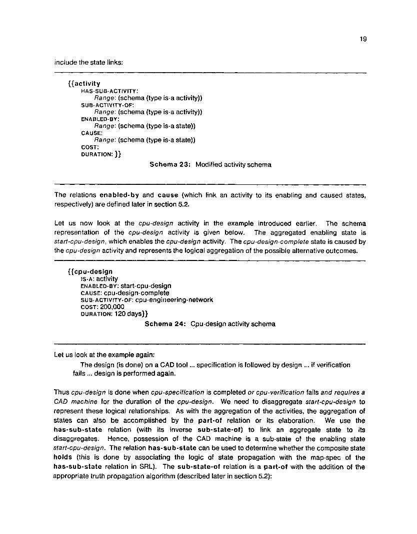
Let us now look at the cpu-design activity in the example introduced earlier. The schema representation of the cpu-design activity is given below. The aggregated enabling state is start-cpu-design, which enables the cpu-design activity. The cpu-design-complete state is caused by the cpu-design activity and represents the logical aggregation of the possible alternative outcomes.
{{cpu-design IS-A: activity
CAUSE: cpu-design-complete SUB-ACTIVITY-OF: cpu-engiiieering-network
ENABLED-BY: start-cpu-design
COST: ~00,000 DURATION: 120 days}}
Schema 24: Cpu-design activity schema
Let us look at the example again: The design (is done) on a CAD tool ... specification is followed by design ... if verification
fails ... design is performed again.
Thus cpu-design is done when cpu-specification is completed or cpu-verification fails and requires a CAD machine for the duration of the cpu-design. We need to disaggregate sfarf-cpu-design to represent these logical relationships. As with the aggregation of the activities, the aggregation of states can also be accomplished by the part-of relation or its elaboration. We use the has-sub-state relation (with its inverse sub-state-of) to link an aggregate state to its disaggregates. Hence, possession of the CAD machine is a sub-state of the enabling state start-cpu-design, The relation has-su b-state can be used to determine whether the composite state holds (this is done by associating the logic of state propagation with the map-spec of the has-sub-state relation in SRL). The sub-state-of relation is a part-of with the addition of the appropriate truth propagation algorithm (described later in section 5.2):

20
Aggregate Leaf State State I
{{sub-state-of IS-A: part-of INVERSE: has-sub-state DOMAIN:
RANGE: Range: (schema (type is-a state))
Range: (schema (type is-a state)) INTRODUCTION: sub-state-propagation-action}}
Predicate Predicate .
Schema 25: The sub-state-of relation
States of the world represent completion of activities, possession of resources, milestones that must be met, their aggregations, etc. While any of these states could be associated with an activity, their roles and characteristics differ. For example, the possession of resources is represented by states which hold (or are "true") for a duration of time, while completion of activities is a one-shot situation [30]. A classification of states is required to properly represent the different types of logical preconditions and aggregations. This classification, which shows two major classes of states, aggregate states and leaf states, is depicted in figure 3. The aggregate state could be an or (disjunct), which is true i f any of its sub-states is true, or an and (conjunct), where all of its sub- states should be true to make the and state true. The leaf states are further classified into status predicates, depicting facts related to activities status and possess predicates, depicting possession of resources for the duration of the activity. The rationale for differentiating between status predicates and possess predicates will be discussed later in the theory of time (see section 5.1).
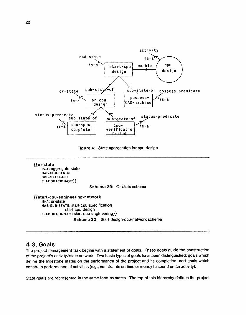
Returning to our example, the states cpu-spec-complete and cpu-verification-failed are aggregated by a disjunct or-cpu-design state. The state start-cpu-design is a conjunct of the or-cpu-design and possess-CAD-machine, The schema representation of these states is as follows:

21
{{start-cpu-design IS.A: and-state ENABLE: cpu-design HA S - SU B- ST A TE: or-cpu -desig n possess- CAD- machine
Schema 26: Start-cpu-design schema
({or-cpu-design IS.A: or-state SUB-STATE-OF: start-cpu-design HAS-SUB-STATE: CpU-SpeC-COmpkte
cpu-verification-failed}} Schema 27: Or-cpu-design schema
{{possess- C A D -in ac h ine IS-A: possess-predicate
REQUIRE: CAD- machine SUB-STATE-OF: start-cpu-design
RESOURCE-UTILIZATION: 100)) Schema 28: Possess-CAD-machine schema
We refer to this aggregation of states as state trees. Figure 4 illustrates the enabling state-tree described before. The enabling state tree, the activity and the caused state tree together define when an activity can be done, what it does and the results it delivers. An activity cluster is an aggregate concept composed of an activity, an enabling tree, and a caused tree. Later sections will further describe this concept and its use as a partition [17].
4.2.2. State Abstraction There is a need to map state information across the levels of activity hierarchy, thus easing the process of project monitoring. For example, the abstract activity, cpu-engineering, starts when cpu-specification is started, and is completed when cpu-verification is completed successfully.
The abstraction of state information is almost identical to the abstraction of activities described before in section 4.1. We need to map the starting of the disaggregate activities to the starting of the abstract activity. Thus, the enabling states of the initial activities form an enabling network, using sub-state-of with conjuncts and disjuncts. This enabling network is an elaboration of the enabling state of the abstract activity. For example, if cpu-specification were a possible starting point for the cpu-engineering activity, the start-cpu-engineering-network, maps the start of start-cpu-engineering to the start of cpu-specification (figure 5).
22
a c t i v i t y
and-state
is-& s ta r t - cpu ena
design
ssess-predicate
design
s ta tus-pred ica te
Figure 4: State aggregation for cpu-design
{{or-state IS- A : aggregate-state
ELABORATION-OF:}}
HAS- SU B-STATE: SUB- STATE-OF:
Schema 29: Or-state schema
{{start-cpu-engineering-network IS-A: or-state HAS- su E-STATE: start-cpu-specification
start-cpu-design ELAEORATION-OF: start-cpu-engineering}}
Schema 30: Start-design-cpu-network schema
4.3. Goals The project management task begins with a statement of goals. These goals guide the construction of the project’s activitylstate network. Two basic types of goals have been distinguished: goals which define the milestone states on the performance of the project and its completion, and goals which constrain performance of activities (e.g., constraints on time or money to spend on an activity).
State goals are represented in the same form as states. The top of this hierarchy defines the project

23
e l ab0rl. t
o r
................................................................. ion-o f el abo,cqtion-of
/'
Figure 5: Aggregation and abstraction of states
/\
s ta tus
goals, breaking them into milestones for smaller time periods. The structure of the goal hierarchy is similar to the structure of the state hierarchy, with part-of relations to provide aggregations and elaboration-of to elaborate the goal into a network of goals/milestones. A network of goals is aggregated into an aggregate-goal using the part-of relation, wnerein goal information can be summed or averaged.

24
{{goal-state IS-A: state))
Schema 31 : Goal-state schema
{{ agg regate-goal TYPE:
Range: (or and or xor)
Range: (type is-a goal-state)
Range: (type is-a goal-state)}}
HAS- PA RT:
EL A B 0 R A TlON - 0 F:
Schema 32: Aggregate goal schema
These goal states also need to be linked to the activities. Whenever an activity is linked to a goal state, its completion must lead to the satisfaction of the goal state. For example, in figure 6, Milestone-2 is a goal-state linked to the activity, cpu-engineering. Whenever, cpu-engineering is completed, it should satisfy the specifications of Mestone-2. The relation must-satisfy is used to link a caused state to a milestone state.
{{must-satisfy IS-A: relation DOMAIN: (type is-a state) RANGE: (type is-a goal-state)}}
Schema 33: The must-satisfy relation
milestone-2 TI engineering
\ / I J
Figure 6: Activity goals
Activity goals such as the cost, the end-time (to be explained in 5.3) and the resources produced by

25
an activity, are specified as bounds on these values (e.g., minimum and maximum admissible values). These goals act as constraints and are attached (in the form of a meta-schema) to the affected slot. Thus the cost goal is attached to the cost slot:
{{activity COST:
Constrained-by: (type "is-a" "goal-constraint")}} Schema 34: Activity schema with cost goal
{{goal-const raint IS-A: constraint
VALUE:}} IMPORTANCE:
Schema 35: Goal constraint
Section 4.4 describes how these goals are used in conjunction with schedules to monitor activities. The details of constraint specification and usage can be found in Fox's thesis [12].
4.4. Instantiation and Manifestation The next step towards the construction of a theory of activity, states, and goals is providing the representational capability to differentiate between prototypical networks, individualized networks, schedules and' actual completion reports. In our interviews with managers, we found that they had the notion of a prototypical network, which they used repeatedly for similar design tasks. For each task they used the prototypical network possibly with some task specific variations (e.g., everything but the power supply design activities). A schedule was generated before starting a task and updated at the end of each milestone (referred to as schedule of Jan 15, schedule of June SO,..). Finally, they create activity completion reports providing the actual start and completion dates for the activities. The project managers relate and enquire about relative location of activities (e.g., what do l do after design), about a schedule (e.g., when does design start in the new schedule), across schedules (e.g., how much will the slip be now, compared to the last schedule) or comparing schedules with actual progress (e.g., how much did we slip in completing design of CPU). Needless to say, there is more than one representation of an activity and a need for linking these diverse representations.
Organizations typically maintain standard procedures (e.g., Engineering Guidelines) which describe the procedure or the activities involved in a task. Even when standard procedures are not maintained formally, people have rich sets of past experiences or scripts [36] stored as prototypical activities and states. For a new task or project, these standard procedures or past experiences are individuated and the new task becomes an instance of the standard procedures. In effect, the set of activities, which comprise the new task, are linked by an instance relation to the corresponding activities and states in the standard procedures.'* For example, cpu-design% 1 is generated as an instance of cpu-design, enabled by start-cpu-design% 1 and causes cpu-design-complete% 1 , where start-cpu-design% 1 and cpu-design-complete% 7 are instances of start-cpu-design and
12Thus, as in Brachrnan [51, instantiation is the process of linking a real thing in the world to a concept.

26
- s t a r t - c p u -
des iQn
cpu-design-complete, respectively.
{{cpu-design% 1 INSTANCE: cpu-design ENABLED-BY: start-cpu-design%l CAUSE: cpu-design-complete%l}}
Schema 36: Cpu-design%l schema
cause /
enable I
Figure 7: Activity hierarchy and individuation
Each activity in the individuated activity network is an instance of a prototypical activity. In other words, the activities are defined elsewhere, and through the process of individuation, the project manager combines these activities to provide the desired result. In real life, the individuation process could be a lot more complex and may involve revisions of prototypical concepts. Hence, there should

27
be a prototypical activity, cpu-specification, which can be instantiated to form cpu-specification% 7 , representing the specification development for Micro-84 cpu version 7 . The project planner may revise the definitions as given in the prototypical activity, cpu-specification at the time of instantiating the activity.
Manifestations [12] are state specific descriptions of the individuals which describe the state at a specific time. For example, the chronicling sub-system of Callisto takes the individuated network and creates manifestations, which represent how and when the activities and states actually progress. For example, the manifestation for cpu-design%7-7 will now be linked to the activity cpu-design% 7 and will provide the progress status and corresponding start and end times.
{{m-cpu-design%l-1 Creation-Date: Jun 30 1983
MANIFESTATION-OF: CPU-design%l MANIFESTATION-TY PE: Scheduled STATUS: active DURATION: {{INSTANCE: time-interval
START-TIME: Jan 14 1984 END-TIME: Jan 21 1984)) }}
Schema 37: Manifestation of cpu+design%l
__
The duration slot points towards a time interval schema (to be described in 5.1). There yay be more than one manifestation of an activity. The manifestations are differentiated on the basis of creation-date and manifestation-type. All the scheduled manifestations are marked scheduled, while the real activity executions are marked manifestation-type real. Figure 7 depicts these networks, where cpu-spec% 1, cpu-design%l and cpu-verif ication%l are the instances for the corresponding prototypical activities, cpu-specification, cpu-design and cpu-verification.
Finally, let us look at the role of goals in relation to schedules and real manifestations. We view goals as a set of commitments, which change gradually with the execution of the project. There are always slips or surprises in the execution of activities, which make it difficult to predict the exact time and cost for an activity. As a result, it is not uncommon to find the scheduled and real manifestations differing in values. Just from these manifestations, it is difficult to ascertain how bad a slip has been in terms of the overall goal (because the future is stili unknown). The goals provide a more steady comparison point. By disaggregating the goal into subgoals or milestones, test points are created at which the status of the project can be evaluated. At each milestone, the project manager makes a decision whether to reschedule (and thus change future milestones) or not. The scheduled manifestations, on the other hand, can be changed dynamically within a milestone to accommodate day-to-day discrepancies in scheduled vs. actual.
5. Theory of Causality and Time Definitions of activities, states, and their abstractions only solve some of the representational problems. A manager would like to know which conditions need to be met before an activity starts. For example, we may assert that cpu-design staffs when cpu-specification is completed and if a CAD machine is available for the duration of the activity. What does such an assertion mean? Does

28
cpu-design start as soon as cpu-specification is completed? Obviously not, as we still need to check for the possession of the CAD machine. Is it sufficient, i f the CAD niachine is available at the time of starting the design, and not later? Probably not, because the CAD machine is needed for the duration of the activity (or the activity can be suspended). We seem to understand such assertions in terms of their temporal and causal implications. It is the purpose of this section to explicitly represent this understanding of the temporal and causal implications.
Rieger and Grinberg have combined causality with temporal relations to develop a classification of cause-effect links [30]. While the resulting representation is explicit, it unnecessarily defines each cross-product of causal and temporal relations (one-shot causal, one shot enablement, continuous causal, continuous enablement, etc). The number of such cross products increases rapidly as we begin to aggregate activities and states using logical aggregations. Also, it is not natural for us to think in terms of such cross products. It is a lot easier to segregate the causal and temporal relations and allow the model to combine any pair of them. Allen [2] has used this approach, though he has not integrated time and causality with aggregation across levels of detail. We have segregated time and causality and have attempted to relate causality and time with aggregation.
We will first define the temporal links associated with the activity networks described earlier in section-4.1. We will also discuss the issues related to granularity in measurement of time. We will then defiiie the causal reiations which connect these concepts and show how they are abstracted to higher levels. Finally, we will discuss issues related to separation between causality and time.
5.1. Theory of Time The cpu-design activity is started i f the cpu-specification is completed. The cpu-specifications should lead to a specification statement, which is used by the design engineers for the design, otherwise one of the specification team members needs to accompany the design team in the design activity.
While such statements are often made by project managers, their usage or query in a model such as ours requires an understanding of the underlying temporal relations. The completion of specification statement and the possession of specification engineer appear to be alternate equivalent states leading to the start of the design activity. While the former is a condition which needs to be "true" at the start of the design activity, !he latter is a possession which needs to be "true" for the duration of the activity. Our model of the activity should reflect the underlying temporal differences in order to relate to project queries, or to provide for a knowledgeable analysis of the alternatives. For example, it should be possible to decide that the cpu-design activity was late because the specifications were not fully generated before starting cpu-design and specification engineers could not be accessed for some time due to their other commitments.
In the modeling of activities, temporal relations provide a weak order of activities (a correlation in time as opposed to causality from one activity to another). For example, the activity cpu-specification occurs during the execution of cpu-engineering-network, and CAD machine is to be possessed for the duration of the cpu-design' activity. There are three salient issues in the representation of temporal information. Firstly, there are differences in representation of relative and absolute time across prototypical networks and their manifestations. Secondly, the temporal information should be

29
abstracted across the levels of activity abstraction. Lastly, we would like to discuss the issues related to measurement and comparison of time in varying granularity.
Representation of time has been a well debated topic [lo, 7, 18, 14, 26, 1,38, 191 and lays the foundation for our work here. We will be using the temporal relations developed by Allen [l], Kedzierski [19], and Smith [%I, which provide an excellent classification of temporal relationships, pictorially depicted in figure 8.
t l before t2 t2 after t l
t l overlaps t2
t2 overlapped-by t l
t l meetst2 t2 met-by t l
f--- t1 - e t 2 3
I U I
t l contains t2
t2 during t l
t i _____, t l .-> < t2 t2 I I
t l same-begin t2 t l same-end t2
t l time-equal t2
Figure 8: The temporal relations
Each of these relations is represented as a schema, with an appropriate function to resolve whether concepts follow a time relation or not [a].

30
{{before IS- A : temporal- relation DOMAIN: (or (type is-a activity)
RANGE: (schema (or (type is-a activity) (type is-a state)))
INVERSE: after}}
(type is-a state))
COMPARE-FUNCTION: compare-before-fn
Schema 38: Before schema
At least two concepts of time were found to occur in the representation of activities. In prototypical activity networks, the representation of time between state and activity within a cluster and between clusters was relational (e.g., cpu-design is done after completing cpu-specification), On the other hand, the temporal definitions for the manifestations of these activities are absolute (having absolute start and end times, e.g., cpu-design staffs on Feb 75). While the relative temporal relationships are required for the former, the latter needs a time-line [38] (as illustrated below) and some way of specifying time granularity.
The first step towards the representation of time is to specify the units of time, a scale and the functions to manipulate time. This is defined by the time-line schema [38]. An example of time-line is the weekly-time-line:
{{ weekly-time-line INSTANCE: time-line POINT-FORM:
(list (sexp (lambda (x) (not (lessp x 0)))) (sexp (lambda (x) (not (lessp x 0))
(not (greaterp (x 52)))))) START-POINT: (1970 0) END-POINT: (1999 52) GRANULARITY:(~ 1) ADD: week-add DIFF: week-diff})
Schema 39: Illustration of time-line
A time interval is defined by a schema as having a start-time, an end-time and a duration. It is dated- by a time-line. An illustration of the time-interval is m-cpu-design% 7- I-duration:
{{m-cpu-design yo -1 -duration START-TIME: (1984 2) END-TIME: (19843) DURATION: (0 1) DATED- BY: weekly- time- line}}
Schema 40: Illustration of time interval

31
The slot point-form describes how a particular time point is represented. For example, in the weekly time-line schema, time is represented as a pair of year and week. The year values are restricted to positive numbers while weeks have lower bound of 0 and upper bound of 52. The start-point indicates the starting point of the time line (e.g., beginning of 7970), while end-point indicates the ending point of the time-line (e.g., end of the year 7999). The granularity slot provides an indication of the precision of the time line. For example, in the weekly time-line, time durations of less than a week are ignored. The slots add and dif f store the procedures to be used for adding time periods and deleting one time period from another, respectively.
5.1 .l. Temporal Relations in State-tree First, let us describe the relational model of time in the state tree. Each relation used in the definition of the state tree has associated with it a temporal relation. These temporal associations differentiate between the one-shot precedence relations and the continuous possess relations. We will examine each of these relations specified earlier and postulate the corresponding temporal definitions.
We postulated two types of leaf states, the status predicates, which model the existence of a condition, and possess predicates which model the possession of a resource. Their temporal descriptions are different. Let us define start-time of a state as the time in the time-line at which the state becomes "true," and end-time as the time at which it becomes "false." The status-predicates are one-shot [30], Le., their start time is well-defined while the end-time is not (only when due to a loop in the activity execution, an activity is repeatedly executed, the end-time may have a meaningful interpretation). For example, the cpu-design-complete becomes "true" when the cpu-design is tompleted, and remains "true" unless the design is redone. On the other hand, the possess-predicates are continuous 1301, Le., both the start and the end time for the state are well defined and mark the period in time for which the state is continually "true." For example, the CAD machine should be possessed for the duration of the cpu-design activity. When a state is to be "true," must be determined by the time-relation explicitly linking the state, and not by any implicit interpretation. This implies that there should be a meet time relation explicitly linking the activity cpu-design to the state cpu-design-complete.
An aggregate conjunct state, composed of status-predicates, becomes "true" when all of its sub- states become true (see figure 9). The sub-state-of relation in such a situation is augmented with an meet relation in time, because the asgregate state is "true" after its sub- state^.'^ Similarly, a composite disjunct state carries an implicit same- begin relation, because the composite state is "true" whenever any of its sub-states are "true" and the two time periods have the same beginning.
An aggregate state, which has possess-predicates as disaggregates, is also continuous. A conjunct of possess states is "true" for the duration of time, when all of its disaggregates are "true." Unless some of them are needed for only part of the activity duration, they have an associated same-end relation. The disjuncts, on the other hand, have a time-equal relation between the aggregate and disaggregate state (see figure 10).
What happens now i f we have an aggregate state, which is composed of both status and possess
13we will ignore the end-time consideration here as it is undefined.

32
1 Pred 1 1 I Pred2 I
AND
SP1
SP2
OR
SP1
SP2
TJ F
TI F
T7 F
Time
T7 F
TI F
T I F I
Time T - True SP1 - Status Pred 1
F - False SP2 - Status Pred 2
Figure 9: Temporal aggregation of status
predicates? This aggregate state will have appropriate temporal relations as described above with each of the sub-states and will be "true" according to the complex logic created by its dis- aggregates. For example, if the cpu-design activity can be started after the specifications are listed in a report or if a member of ?he specification team can be possessed for the duration of the design activity, then the disjunct state is same- begin with the status-predicate (Le., completion of specification report) and time-equal with the possess-predicate possession of a person to explain specifications) and the disjunct state is, then, needed to be true for the duration of the cpu-design activity (see figure 11).
There are many such alternatives and there may be any number of such composite states in a hierarchy of state tree. It is not feasible to define a complex relation for each one of these which combines a temporal characteristic with an aggregation characteristic. It is much easier to have aggregation and temporal relations coexisting in a model of the activity, so that any of these combinations can be generated and used to interpret relative temporal associations according to need. This segregation also facilitates representation of other complex temporal relations, e.g., overlapping states and activities.

33
AND AND
PP1
Possess Possess pp2 Pred 1 Pred 2
I OR I OR
I
Time
TI F
Time T- True
F - False
PPI - Possess Pred 1
PP2 - Possess Pred 2
Figu re 10: Temporal aggregation of possession
5.1.2. Temporal Aggregation of Activities The su b-activity-of relation carries the temporal definition of during, because the sub-activities are always done within the duration of their aggregate activity. For example, cpu-specification is done during the execution of the cpu-engineering-network. Hence, if the start or end time for specification are not given, a rough estimate can be inherited from the higher level activity. The definition of the relation sub-activity-of can now be extended as follows:
{{su b-activity-of Is-A: part-of during}}
Schema 41 : Sub-activity-of relation
As opposed to the state hierarchy, the relationship in activity aggregation is consistently a temporal during relation, irrespective of the type of aggregation (conjunct or disjunct). The network in turn is an elaboration of an activity at a more abstract level and has a time-equal relation with the abstract activity.

34
AND AND Tn F
OR
SP1
Status Possess PP2 Pred 1 ~ Pred2 ,
7
7
F
F
Tn Time
T - True SP1 - Status Pred 1
F - False PP2 - Possess Pred 2
Figure 1 1 : Complex temporal aggregation
5.1.3. Time Granularity Schedule predictions and actual completions, on the other hand, specify absolute time. Consequently, the manifestations carry explicit information on start and end time for the manifestation. For example, the schedule for specification could specify a start-time of Jan 15 and an end time of Feb 10.
Granularity of time was defined earlier in this section as the precision of the associated time-line. The granularity of measurement needs to be defined both for the specification and the comparison of temporal information. The specification of start or end time of a manifestation implicitly contains a time-granularity. For example, the statement, the cpu-design activity will be cornplefeed in March, uses the granularity of month (this definition of time is at a more aggregate level compared to the weekly time-line we saw earlier). Similarly, the determination of whether two overlapping manifested activities occurred before, after, or during one another is dependent upon the comparison granularity. For example, i f the activities cpu-specification and cpu-design are both done in the same quarter, they are time-equal at the granularity of quarter, while they may meet at the granularity of a day, and may be related with an after relation at the granularity of aseccmd.

As explained before, the concept of time-line is useful in specifying the granularity, and hence two time-intervals in absolute time can be compared using two different functions in different granularities. The compare-function given in each temporal relation uses the granularity of the time- line to adapt to the appropriate time-granularity.
While being compared, the two time-periods (or time-points) may be specified in the same or different granularities. It is relatively easy to compare two time periods having the same granularity (e.g., the first week of March is before the first week of April) by using the compare function stored in the temporal relation^.'^ Consider a situation where the two time intervals are specified in two different time granularities (e.g., 1984 first quarter and Feb-Apr 1984). One may wish to transform one time interval from one level of granularity to another before comparing and deducing the relationship (e.g., that 1984 first quarter is equivalent to Jan-Mar and hence overlaps with Feb-Apr). The question is whether such a transformation should be done on the less precise or the more precise time interval. The transformation from a more precise to a less precise time-line involves an approximation, and hence, it is better to transform the time-interval in quarters to the one in months and, then, apply the compare function. Time-points need to be converted into time intervals before such a comparison can take place. Thus, 1984 first quarter as a time point cannot be compared with Mar 19, till we convert it into a time period (i.e,, Jan 1-Mar 31 1984), and, then, it can be deduced that 1984 first quarter contains March 19,1984.
5.2. Theory of Causality In the project management domain, causation of one activity by another is central to the planning, scheduling and chronicling of activities. We will describe here the causal primitives necessary for such a system. These causal primitives should facilitate the reasoning of causation across the activities and states. For example, someone may want to know Which activity is caused by cpu- specification?, Which are the previous-activities of cpu-design?, or I f cpu-engineering is initiated, which sub-acfivities are started as a result?. The scheduling and chronicling systems are likely to use this causal reasoning to move through the activity network for generating a schedule or for deciphering whom to report the progress, respectively.
A number of models have been developed for tracking the progression of change or "truth" in a set of states (e.g., Petri nets [28] and ICN 181). Unfortunately, these models work on "flat" networks, Le., having RO aggregation or abstraction levels. We introduced aggregation and abstraction at three levels: in a state tree to describe the composite state enabling or caused by an activity, in an activity network to describe activities at different levels of detail or aggregation and lastly, abstraction of states across activity hierarchy. To answer the queries raised in the previous paragraph, one needs to know the causal implications for each of these three situations. For example, it is equally correct to say that the start of cpu-specification causes the start of cpu-engineering as it is to assume the causality top-down from cpu-engineering to cpu-specification (see figure 12). In the project management environment, it is simply a matter of reporting vs directing and, thus, both causality directions are equally plausible.
l4To do such a comparison, the compare function accesses the granularity and point form of the two intervals and makes an arithmetic comparison of the two tuples.

36
s ta tus pred ica te
engineer ing
e l abor I t i o n - o f
o r /r stace I
s ta tus pred ica te
spec i f i- c a t i o n
Causal i t y
top-down bottom-up
I
/
\
Figure 12: Causality and abstraction
Causality is stronger than temporal association. In the definitions of temporal relations, meets only specified the correlative occurrence of the two time intervals, without any causation. Causation specifies an order of occurrences, and has associated with it the temporal relations. In other words, temporal relations can exist without causation, while causal relations imply temporal association. Each aggregation node in the activitylstate network has, associated with it, a two-way causation, which needs to be used for evaluating whether a state is "true" or not. For example, if a conjunct node is "true," so are its sub-states. Similarly, if the sub-states of a conjunct state are "true," so is the conjunct state.
The three basic relations linking states to other states and activities: enable, cause and has-sub-state, need to be formally defined to include the causality of status propagation from one state or activity to another:
Enablelenabled-b y As and when a state is linked to an activity with the enable relation, it introduces a new propagation- action function, so that whenever the (domain) state is true, it starts the (range) activity. For example, cpu-design is started when sfart-cpu-design is true.

37
{{enable IS-A: relation
DOMAIN: (type is-a state) RANGE: (type is-a activity) INTRODUCTION: enable-propagation-action}}
INVERSE: enabled-by
{{enable-p ropagation-action INSTANCE: introduction-spec NEW-SLOT: propagation-action NEW-VALUE: start-activity-fn}}
Schema 42: The enable relation
In the above description, the enable-propagation-action is introduced when the enable link is formed between the activity and its enabling state.15 The start-activity-fn is a lisp function which is attached to the enabling-state (e.g., start-cpu-design). Whenever a propagation-action message is sent to the enabling state (a la object programming), it generates a manifestation of the activity and records the activity status as active.
Cause/caused-by The cause relation is similar to the enable relation, except that causation flows from the activity to a state. Whenev.er the activity changes its status, the change is propagated to the caused state. For exampie, the completion oi design-cpu makes design-complete true (by sending a message to activate the updafe-status-fn in the propagation-action slot of the activity.
{{cause IS-A: relation INVERSE: caused-by DOMAIN (type is-a activity) RANGE: (type is-a state) INTRODUCTION: cause-status-action}}
{{cause-status-action INSTANCE: introduction-spec
NEW-VALUE: update-status-fn}} NEW-SLOT: propagation-action
Schema 43: Cause relation
Has-sub-s ta te/sub-s tate-of The aggregation of states implies a two-way causality. Any changes in the status should lead to status changes in the other states in the hierarchy depending on the logical aggregation type used in the aggregation hierarchy. For example, the or-state in the design-cpu example should change its status whenever either of its disaggregate states changes in the status. The propagation-action slot
"For details of introduction-specs, please refer to [ll, 441.

38
is dependent on the type of aggregation and is defined for the or-state and the and-state scheinata.l6
{{or-state IS- A: aggregate-state PROPAGATION-ACTION: or-propagate}}
Schema 44: Or-state schema
({and-state IS-A: aggregate-state PROPAGATION-ACTION: and-propagate}}
Schema 45: And-state schema
Finally, the truth-propagation for the leaf-states needs to be defined. A status predicate is true i f it is currently manifested (i.e., it has a manifestation which is active, and, thus, has a start time but no end time), or i f its elaborations are true. A possess-predicate is true i f it is currently manifested otherwise a message is sent to the resource manager for the required resource requesting a possession of the resource.
{{status-predicate IS-A: leaf-state PROPAGATION-ACTION: update-status-predicate-fn}}
Schema 46: Status predicate schema
{{possess-predicate IS-A: leaf-state PROPAGATION-ACTION: request-resource-manager-fn}}
Schema 47: Possess predicate schema
Truth propagation Are the above causal definitions sufficient to define causation in activity networks? We need to look at the propagation of causation from one activity to another to analyze whether the definitions given above lead to a non-ambiguous description of the causal flow. We will assume that each time the system simulates the activity network to generate a schedule, the following sequence of steps will be executed:
16The or-propagate function simply applies a lisp "or" function to the evaluation of status by its sub-states, obtained by sending object programming messages. The and-propagate applies a lisp "and" instead.

39
s tar t -cpu-
t r u e ?
x e r i ng- rk J
t r ue?
Figure 1 3: Propagation of causality I
1. The user initiates the a ~ t i v a t i o n ' ~ of the cpu-engineering activity, which involves sending a message to the state start-cpu-enginnering, to propagation-action, thus asserting that the state start-cpu-engineering is true (figure 13).
\ / 4 t r u e
- 4
2. As the state, start-cpu-engineering, is a status-predicate, its propagation-action function, upddte-status-predicate-fn, sends a message to its elaboration, start-cpu-engineering-network and creates a manifestation of start-cpu-engineering if the message returns a true.
s tar t -cpu- speci.-
3. The state start-cpu-engineering-network is an or-state. The propagation-action function of an or-state creates a manifestation of the or-state, if any of the messages sent to its sub-states returns a true. A message is thereby sent to the states, start-cpu-specification and start-cpu-design, for propagation-action.
\ ,
cause.
cpu-spec- camp 1 e t e \
4. The state start-cpu-specification is a status-predicate without any elaborations, and hence can be made true. As a result, start-cpu-engineering-network and start-cpu-engineering are ais0 made true. The propagation-action slot of start-cpu-specification has a function, which involves sending a message to the
"The activation of an activity implies asserting that the activity is ready for execution. An activity can be activated either by the user, or through the causation from one activity to another, as illustrated later.

cpu -specification activity to s t a r t . l8
5. The completion of the cpu-specification involves searching for a state in the caused state tree, whose status matches with the status of the activity, and sending a message to that state to propagation-action. In this case, the propagation-action message is sent to the state, cpu-spec-complete. As the state, cpii-spec-complete is a status-predicate with no further elaborations, a manifestation is created.
6. Now, we face a problem. In order to propagate further, we now have to move up in the enabling state tree from cpu-spec-complete to start-cpu-design (figure 14). There are two ways of achieving it:
0 A propagation action can be defined for moving up the state tree along the sub-state-of relation. But, as we have already defined a propagation action for moving down the has-su b-state relation, the states cpu-spec-complete and or-cpu-design will end up sending messages to each other ad infinitum.
0 We can find the next-activities of cpu-specification linked through cpu-spec-complete, activate each one of them, and follow the same logic as we did for cpu-specification and cpu-engineering activities.
Following the second approach, we somehow find (to be explained, in detail, later in this section) that the activity, cpu-design, is to be activated. A message is sent to the state, start-cpu-design to initiate a propagation-action,
7. As start-cpu-design is an andestate, it can not be true unless all of its sub-states are true. A message is sent to or-cpu-design and possess-CAD-machine to initiate propagation-action.
8. The or-cpu-design sends a message in turn to cpu-spec-complete and cpu-verification-failed, receives that cpu-spec-complete is true and, thus, responds in turn to start-cpu-design with a true message.
9. The state, possess-CAD-machine is a possess-predicate. In order for it to be true, it needs to possess the CAD-machine. A message is, thereby, sent to the resource manager of the CAD-machine requesting the use of the CAD Machine for the duration of cpu-design and a false is sent back to start-cpu-design,
10. When the resource manager for CAD machine decides to allow the possession of the CAD Machine for the cpu-design, a possession messagelg is sent to the cpu-design and the process of propagation-action is repeated for the state, start-cpu-design.
The t ruth-propagation algorithm described above leaves one question unanswered-how are we going to find out that the activity, cpu-design should be activated when the activity, cpu-specification
18Starting an activity involves a number of actions: setting the status to active, making a manifestation of the activity, and
"Similar to the activation message, a possession message informs the activity that the needed resource is available and
scheduling the activity completion at the scheduled end-time of the activity (which is start-time + the duration of the activity).
that the activity can be started.

41
design
t r u e ? s ta r t - cpu - design
or-cpu- possess-CAD design mach i ne
request t r u e ?
cpu-spec- c p u - v e r i f i . \/
comp 1 e t e f a i l e d -
resource- manager
Figure 1 4: Propagation of causality I1
is completed? This question turns out to be non-trivial. Let us explore it further by defining the transitivity of a relation which moves across the state trees from one activity to its next activities:
1. The first step in such a relation is to move along a cause relation from an activity to the top of its cause-state-tree. Thus, from cpu-specification, we move to cpu-spec -complete.
2. The next step could be that of moving down a has-sub-state relation (e.g., from cpu-verification-complefe to cpu-verification-failed, or moving up a sub-state-of relation (e.y., from cpu-spec-complete to or-cpu-design). As it turns out, there may be any number of such sub-state-of or has-sub-state relations.
3. Finally, one has to move from a state to an activity by moving along a enable relation (e.g., from start-cpu-design to cpu-design).
The problem comes from the fact that we had to move both up and down the state trees. There is no consistent way of ensuring that we stop at only the next activities of the activity that we started with. Let us consider the situation in figure 15. We would like to model a network where activity a1 has two alternative outcomes-s727 and s722. Another activity, a2, has a single outcome, s22. Activity a3 starts when a7 causes s722 or a2 causes its completion, s22. Also, activity a4 starts after a2 results in s22. There is nothing to inform the "transitivity" algorithm, which attempts to move from s72 to s722, that after having moved to s37, it should not move to s22. This portrayal of state trees does not have

42
s12 c
an associated concept of causality, which would have differentiated between movement from s122 to s3 1 and from s3 1 to s22.
s31 -
I '3
Legend 0 activity
Figure 15: Causation: problems in transitivity
Let us diagnose the problem a little more closely. Each status predicate in our network stands for two descriptions. First, that a condition is met due to the ending of an activity (e.gS1 failure of verification at the end of the verification activity). Second, that this condition is one of the states required for starting a new activity (e.g., starting design due to failure of verification). It is tempting to use one state to signify both of the above, as it is done in the state space approach [28,8]. While modeling simple activity networksl these two states naturally collapsed together without adding any ambiguity to the definition of next-activities. In figure 16, the flow of causality moves from activity a7 to state s72, from activity a2 to state s22 and then from these two states to their conjunct s37, and finally from state s31 to activity a3. Here, the same state s72 signified the completion of activity a7 and a condition for starting activity a3. We should be able to model this network with s37 as a conjunct state made of two leaf states s72 and s22.

43
-
Aggregation among activities and states introduces ambiguity. As we saw in figure 15, the state space approach is clearly inadequate for dealing with arbitrarily complex activity and state combinations.
s22
Legend
activity 0 I I state
Figure 16: Causation: state space approach
One way of dealing with the problem of transitivity of causality and "truth propagation" is to define two causal links for each sub-state/sub-activity relation. Each state in such a network would be a part of a causal chain at a level of abstraction, and there would be additional links to relate to higher levels of abstraction (figure 17 illustrates this approach). Although this approach is explicit, it ignores the implications from the semantics of aggregation and abstraction relations and increases (unnecessarily) the number of causal relations.
We see a need for separation of causality from aggregation. This involves the modeling of causality separately across the activity clusters (defined earlier in section 4.1) and using the state trees for ascertaining causality within an activity cluster. It looks reasonable to follow this approach because activity cluster is an aggregate concept capable of reasoning within itself to provide the direction of

44
State 1 - sub-state-cause 2 - sub-state-of-cause 3 - sub-state-caused-by 4 - su b-state-of -caused- by * I State 1
Figure 17: Causation: multiple link alternative
causality. We use the relation cause-enable to link the caused state associated with one activity to the corresponding enabling state of its next activity. Hence, cpu-spec-completion, the caused state associated with specification has a cause-enable link to start-cpu-design-c 7 . Within the activity cluster for cpu-design, the transitivity algorithm can move along the state aggregation from the leaf states to the top of the tree. The illustration in figure 15 now changes to figure 19.
This approach involves the definition of the state s722’ as a mirror image of s722, which is true whenever the latter is true. An added benefit of the inclusion of activity clusters is that they reduce the complexity of activity editing. Activities are modular, hence are easier to insert and modify without worrying about interactions with other states.
The cause-enable relation was introduced to separate clusters. The link is not only used. to separate but also to propagate state changes. For example, when cpu-verificafion fails, the cause-enable relation, which connects cpu-verification activity cluster to cpu-design, propagates a change in status and, thus, initiates the start of cpu-design. The enabling state tree for cpu-design, represents the other requirements for starting specification, Le., having the CAD machine. Once the CAD machine is available, it fulfills the condition for starting cpu-design, and propagates the causation to the cpu-design activity itself by forming a manifestation of the cpu-design, with an appropriate start-time.
Cause-enablelena ble-cause The cause-enable relation allows propagation of status from one state to another. Whenever the domain state changes its status, the range state should also change its status accordingly.

45
s p e c i f i c a t i o n
possess- CAD-inac h i ne
s t a r t - c p u - design-c2
cause -enab le (meet)
q u s e c p y v e r i f i - v e r i f i c a t i o n / c a t i o n -
cpu-ver i f i - c p u - v e r i f i- c a t i o n - c a t i o n -
f a i l e d succeeded
Legend
a c t i v i t y
I I
Figure 18: Activity clusters illustration

46
. S I 2
SI 21 SI 22
state
Figure 1 9: Causation: aggregations and cause-enable
{{cause-enable IS-A: relation INVERSE: enable-cause DOMAIN (type is-a state) RANGE: (type is-a state) INTRODUCTION: cause-enable-propagation-action}}
{{cause-enabie-propagation-action INSTANCE: introduction-spec NEW-SLOT: propagation-action NEW-VALUE: create-manifestation-fn}}
Schema 48: The cause-enable relation

47
5.3. Time, Causality and Goals Having defined time and causality, let us look at their association. We have found that causality is a stronger association of the two because it implies the temporal association as well as the direction of causation. At the same time, there are a number of combinations generated from the association of time, causality and aggregation and we do not have a small set of combinations, which could be labeled and used together. We would like to raise here two issues related to time, causality and aggregation. First, how are the temporal and the causal links related? Second, what is the role of goals and milestones?
We have employed many of the causal relations given [30], but have described time separately. This separation enables activities to be causally linked with a temporal relation ascribed separately. In general, there is no need to assign a specific temporal link as the process of causation (i.e., the "truth" propagation) will generate a temporal association in absolute time and a similar system can simulate the causal reasoning to derive the relative temporal associations. For example, i f no temporal associations are provided, the system can reason through the network to assume that specification is completed before starting design. The temporal relations at the same time provide additional information not available in the causation (e.g., specification can overlap with design)
The goal-states defined earlier imply a need for causation from an initial state to a goal state. The question is what these goals imply in terms of time and causality? In particular, the must-satisfy relation projects what should happen. What does this must-satisfy relation imply in terms of causality, and how should the "truth-propagation" deal with the must-satisfy relation, and finally, which of the time-relations should be associated with the must-satisfy relation?
The status of goals are different from "true" and "false." A goal is either inactive, active or satisfied. When the goal is generated, it is inactive as no activity is actively pursuing the achievement of the conditions specified in the goal. The enablement of the attached activity leads to a change in the goal state from inactive to active. The active status of the goal implies that an activity is being pursued to meet the goal. If the completion of the activity meets the conditions specified in the goal, it satisfies the goal. The goal state is manifested for each of the three above mentioned states by the respective actions, viz., enablement of the enabling state tree and causation of the caused state tree. The manifestations carry a status value and a time interval during which the goal was in the Specified status. Thus, the goal for version 1 of cpu-engineering%l is set to active as and when the start-cpu-engineering% 7 activity is manifested. The goal is satisfied, wnen the cpu-engineering% 7 is completed (see figure 20).
6. Theory of Relational Abstraction When we walked into the application environment, the first couple of sessions were spent in understanding the meaning of words used. Terms like ECO, revisions, components, etc. had specific meanings associated. Once we generated the semantic representation, we had to generate abstract relations to conform to the managers' vocabulary.
It is interesting to note that while the jargon seemed obtrusive to people outside the organization, it was used freely within the organization, with no ambiguities. When we examined the meaning, we could theorize and represent the underlying semantics. Organizations develop their own languages

48
s t a r t - cpu- e n g i n e e r i n g %1
J
milestone-2 u cause r - e y b l e \ cpu-
/ / engineering
c o m p l e t e %1 s t a r t - cpu- eng i
I -
Legend cu r ren t man i fes ta t ion
- milestone-2
man i fes ta t ion I
I
Figure 20: Status of goal
and everyone communicates in these languages, despite the fact that the language used will not be understood by outsiders. In this section, we will discuss the rationale behind these domain languages and the related issues of representational complexity and distance. Unfortunately, the underlying semantic representation is usually available in the minds of the system designers alone. In our representation, it is possible to overlay the domain structure over the semantic structure and change the domain layer from organization to organization or from one application to another.
a c t i v e
rnust-sat isfy
. . l < f l P d , \
Another reason for overlaying abstract relations is the complexity of the representation. While the explicit representation of time, causality, etc., is theoretically satisfying, in practice it places a heavy
cause - eryb le \
/ / s t a r t - cpu- .
engineering
cpu- 3
engineer ing complete %1
I I *

49
burden on the creator of the model. It is obvious to the model builder how activity clusters are formed and traversed, but in applying these concepts for perusing the data-base, the model builder or the user would like to use more abstract relations. The problem here is one of representational distance, that is, how complex is the transformation of surface level concepts into the representation primitives. Frame systems provide a partial solution similar to abstract data-types; a frame represents an aggregation of properties and structure. The SRL language used by Callisto, also provides relation abstraction. Hence, "higher level" relations may be defined.
For example, let us develop a relation next-activity-of, which links two activities, causally linked to each other. We would like to infer that cpu-design is next-activity-of cpu-specification. In the model developed in section 4, we described that cpu-specification causes cpu-spec-complete, which has a cause-enable link to start-cpu-design-c 1, which in turn is the sub-state of or-cpu-design. The slate or-cpu-design is sub-state of start-cpu-design, which enables the activity cpu-design. The relation next-activity-of is an abstraction of this detailed description. The relationship between the abstract relation and its elaboration are provided by defining the transitivity of next-activity-of in terms of the basic relations used at the semantic level. The schema representation of next-activity-of is as follows :
{{next-activity-of IS-A: relation INVERSE: has-next-activity DOMAIN: (type is-a activity) RANGE: (type is-a activity)
(list (step enabled-by all t) (repeat (step has-sub-state all t) 0 in9 (step enable-cause all t) (repeat (step sub-state-of all t) 0 in9 (step caused-by all t))}}
TRANSITIVITY:
Schema 49: The relation next-activity-of
The user could query whether the activity cpu-design is next-activity-of [cpu-specification], or could get a list of activities, each of which are next-activity-of cpu-specification.m
Linguistic level relations [5] may be formed with any combination at the conceptual or epistemological levels. Hence, if the project manager intends to specify sub-operation-of as a sub-activity-of for the manufacturing domain, he should be able to specify it by defining the sub-operation-of relation as follows :
the representation of this relation, we have specified the following transitivity grammer for the relation: In order to relate two activities using this relation, one has to traverse one enabled-by relation, any number of sub-state relations (which take us down the enabling state tree), one enable-cause relation (which takes us to the caused state tree of the other activity), any number of sub-state-of relations to go up the caused state hierarchy and finally a caused-by relation to reach the activity.

50
((su b-operation-of IS-A: sub-activity-of DOMAIN: (type is-a operation) RANGE: (type is-a operation) INVERSE: has-sub-operation TRANSITIVITY: (Step sub-activity-of all t)}}
Schema 50: Sub-operation-of schema
To summarize, the purpose of relational abstraction is two fold. First, i t provides a way of representing relations, which are abstractions of detailed semantic representation. This abstract representation reduces the semantic complexity that the model builder or the user has to deal with. Second, it helps translation of domain concepts to more general semantic concepts.
7 . Conclusion We started with a goal of developing a representation language which satisfies the criteria of completeness, precision and lack of ambiguity. In the process of developing the representation language, we integrated the theories of activity, time, causality, manifestation and instantiation. The integration process raised a number of issues: first, the need for separation of time and causality; second, the difference between one-way causation (the cause-enable relation), and two-way causation (the has-so b-state and sub-state-of relations); and finally, the difference between the aggregation process of building a whole From its parts, from the abstractiQn process of reducing information from one level of detail to another.
A formal evaluation of these theories is an article in itself. We will concentrate here on the example listed in section 2 and evaluate the theories in terms of their completeness, precision and lack of ambiguity.
Evaluation of Completeness The criterion of completeness requires that the representation spans the application domain. The project management tasks need models of the required activities; their duration; precedence, resources; time; logical (causal) connections; individual and prototypical plans; constraints and organization for conflict resolution. This article includes the definition of the activities, the states or conditions enabling the activity, and those caused by the activity. It covers the activity precedence and resource requirements, individual and prototypical plans, and alternative manifestations, as well as the temporal and causal relations linking these activities and states. The concepts related to project environment, i.e., the organization for conflict resolution, are described in Sathi and Fox [35]. The theory of constraint can be found in Fox’s thesis [12]. At the same time, the theory falls short in the description of activity attributes (e.g., cost, duration, product or state transformation details), the procedures for aggregation and abstraction of activities and states (e.g., the operations needed for aggregation - averaging, summation, etc., and the types of attributes for each of these operations), and the use of classification relations for categorizing and generating group characteristics.
51
Evaluation of precision Precision requires description to be at the appropriate granularity of knowledge, Le., the precision used in the project management communication. The theory is considered successful, if the sentences in the example can be translated into a set of concepts which replicate the descriptions in the sentences. Using relational abstraction, a number of higher level statements can be faithfully replicated (e.g., specification is followed by design). At the same time, the theory is capable of describing the situation in a lot more detail (e.g., what conditions need to be met before during the cpu-design activity? or during the cpu-design activity?). Thus, a user can choose the appropriate level of precision in describing plans, schedules or progress in a project.
Evaluation of clarity Clarity of the theories can be evaluated by ensuring that there exists one and only one representation for a given situation. These are two likely sources of ambiguity: inconsistency -and incompleteness (of which completeness is covered above).
Inconsistency implies there exist two or more project descriptions which, when put together give rise to a conflict. For example, if managers use different PERT based networks for project descriptions at different levels of the managerial hierarchy, the descriptions may suffer a lack of common updating procedures. Similar problems have been observed during plan generation and scheduling of projects. We aimed at providing explicit details not only to avoid incompleteness but also to achieve the integration of concepts so as to avoid inconsistency. For example, the integration of cpu-engineeriiig activity with cpu-engineering-network ensures that the status information remains consistent between the two levels of detail. The specifications and changes made in planning, scheduling or chronicling, are integrated at multiple levels in the managerial and project hierarchy, not only across levels of management, but also within a level from one department or unit to another. In this way the introduction of inconsistency is minimized and inconsistencies that do exist are brought to the surface.
Research tends to raise as many questions as it answers. Our work is no different. It raises issues in two directions:
0 Whether the experimental system. developed here can be applied to "real-life" large engineering and manufacturing projects. A number of questions are often asked. For example, how much of detail is really needed? How easy will it be to use? How bulky will it be? Would it be adequate for all project management needs? While such large projects involve 5,000 or more activities, no manager ever reviews more than 100 activities at a time. The major short-coming of the existing commercial packages is their inability in summarizing or focusing on the 100 relevant activities. While our research paves the way, the techniques for presenting summaries and foci are yet to evolve.
0 The activity representation is similar across the various application domains. While we developed a set of semantic primitives, they need to be validated on a large number of domains. It would be worth while. to explore the similarities and differences across domains, specially in their inheritence considerations.

52
Acknowledgements
This work is a part of the CALLISTO project. We would like to acknowledge the helpful comments from Roy Smith, William Sears, Greg Mangan, Richard Glackemeyer, Stephen Smith, Edward Screven and Pamela Gage.

References
1 . Allen, JF. "Maintaining Knowledge about Temporal Intervals." Communications of the ACM 26
2. Allen, J.F. "General Theory of Action and Time." Artificial lntelligence 23, 2 (Jul 1984).
3. Bobrow, D and T Winograd. "KRL: Knowledge Representation Language." Cognitive Science 7 , 1 (1977).
4. Brachman, RJ. A Structural Paradigm for Representing Knowledge. Ph.D. Th., Harvard University, Cambridge, MA, May 1977.
5. Brachman, RJ. On the Epistemological Status of Semantic Networks. In NV Findler, Ed., Associative Networks: Representation and Use of Knowledge by Computers, Academic Press, New York, NY, 1979, pp. 3-50.
6. Brachman, RJ. "What is-a and isn't: An Analysis of Taxonomic Links in Semantic Networks." /€E€ Computer (October 1!383), 30-36.
7. Bruce, BC. "A Model for Temporal References and its Application in a Question Answering Program." Artificial lntelligence 3 (1972), 1-25.
8. Ellis, C. Information Control Nets : A Mathematical Model of Office Information Flow. Proceedings ACM Conference on Simulation, Measurement and Modeling of Computer Systems, ACM, 1979.
9. Fahlman, SE. A System for Representing Real World Knowledge. Ph.D. Th., MlT, Cambrige, MA, 1977.
(NOV 1983), 832-843.
10. Findler, NV and D Chen. On the Problems of Time, Retrieval of Temporal Relations, Causality, and Co-existence. The Second International Joint Conference on Artificial Intelligence, IJCAI, 1971 , pp. 531 -545.
11. Fox, MS. On Inheritance in Knowledge Representation. Proceedings of the Sixth International Joint Conference on Artificial Intelligence, Tokyo, Japan, IJCAI, 1979.
12. Fox, Mark S. Constraint Directed Search : A Case Study of Job-Shop Scheduling. Ph.D. Th., Computer Science Dept, Carnegie Mellon Univerisity, Pittsburgh, PA 1521 3, 1983.
13. Goldstein, I and B Roberts. NUDGE, A Knowledge-based Scheduling System. The Fifth International Joint Conference on Artificial Intelligence, IJCAI, 1977, pp. 257-263.
14. Hayes, PJ. The Naive Physics Manifesto. In D. Michie, Ed., Expert Systems in the Micro Electronic Age, Edinburgh Press, UK, 1979, pp. 243-270.
15. Hendrix, GG. "Modeling Simultaneous Actions and Continuous Processes." Artificial Intelligence 4,3 (1973), 145-180.
16. Hendrix, GG. Expanding the Utility of Semantic Networks through Partitioning. Fourth International Joint Conference on Artificial Intelligence, Tiblisi, USSR, IJCAI, 1975.
17. Hendrix, GG. Encoding Knowledge in Partial Networks. In Findler, NV, Ed., Associative Networks, Representation and Use of Knowledge by Computers, Academic Press, New York, 1979.

18. Kahn, KM and AG Gory. "Mechanizing Temporal Knowledge." Artificial Intelligence 9,2 (1977), 87-108.
19. Kedzierski, 81. Knowledge-based Communication and Management and Support in a System Development Environment. Ph.D. Th., Computer Science Department, Univ of Southwestern Louisiana, Nov 1983. Also available as Kestrel Technial Report KES.U.83.3, Kestrel Institute, Palo Alto, Ca
20. Kelley, JE and MR Walker. Critical-Path Planning and Scheduling. Proceedings, Eastern Joint Computer Conference, , 1959.
21. Lee, RM. CANDID: A Logical Calculus for Describing Financial Contracts. Ph.D. Th., Dept of Decision Sciences, The Wharton School, Univ of Pennsylvania, Philadelphia, PA, 1980.
22. Lenet, D. AM : An Artificial Intelligence Approach to Discovery in Mathematics as Heuristic Search. Ph.D. Th., Computer Science Department, Stanford University, Palo Alto, CAI 1976.
23. Levy, FK, GL Thompson and JD Wiest. "The ABC of the Critical Path Method." Harvard Business Review (Oct 1963).
24. Malcolm, DG, JH Rosenboom and CE Clark. "Application bf a Technique for Research And Development Program Evaluation." Operations Research (Sep-Oct 1959).
25. McCarthy, J. Situations, Actions and Causal Laws. Tech. Rept. AIM.2, Stanford University, Palo Alto, CAI July 1963.
26. McDermott, D. "A Temporal Logic for Reasoning about processes and Plans." Cognitive Science 6 (1982), 101-155.
27. Meehan, JR. Everything You Always Wanted to Know About Authority Structures but were Unable to Represent. First National Conference of Artificial Intelligence, AAAI, 1980.
28. Peterson, JL. "Petri Nets." Computing Surveys 9 , 3 (September 1977), 224-252.
29. Quillian, MR. Semantic Memory. Ph.D. Th., Carnegie Mellon University, Pittsburgh, PA, 1966.
30. Rieger, C and M Grinberg. The Declarative Representation and Procedural Simulation of Causality in Physical Mechanisms. Proceedings of the Fifth International Joint Conference on Artificial Intelligence, IJCAI, 1977, pp. 250-255.
3 1 . Roberts, RE and IP Goldstein. The FRL Primer. Tech. Rept. Memo # 408, MIT AI Lab, Cambridge, MA, 1977.
32. Sacerdoti, ED. Planning in a Hierarchy of Abstract Spaces. Third International Joint Conference on Artificial Intelligence, IJCAI, 1973, pp. 412-422.
33. Sacerdoti, ED. "Planning in a Hierarchy of Abstract Spaces." Artificial lntelligence 5 , 2 (1974), 1 15-135.
34. Sathi, A, MS Fox, M Greenberg and T Morton. Callisto : An Intelligent Project Management System - Overview. Carnegie Mellon University, Pittsburgh, PA 15213,1985.
35. Sathi, A and MS Fox. Modelling of Project Environment. Under preparation, ISL, Robotics Institute, Carnegie Mellon University

55
36. Schank. R and R Abelson. Scrips, Plans, Goals and Understanding. Lawrence Erlbaum Assoc, Hillsdale, NJ, 1977.
37. Schubert, LK. "Extending the Expressive Power of Semantic Networks." Artificial Intelligence 7 (1 976), 163- 198.
38. Smith, SF. Exploiting Temporal Knowledge to Organize Constraints. Tech. Rept. CMU-RI- TR-83-12, ISL, Robotics Institute, Carnegie Mellon Univerisity, Pittsburgh, PA 15213, 1983.
39. Stefik, M. An Examination of a Frame-Structured Representation System. Proceedings of the Sixth International Joint Conference on Artificial Intelligence, Tokyo, Japan, IJCAI, 1979.
40. Tate, A. Generating Project Networks. The Fifth International Joint Conference on Artificial Inteiligence, IJCAI, 1977, pp. 888-893.
41. Turban, E. The Line of Balance - A Management by Exception,Tool. In EW Davis, Ed., F,ajezt Management : Techniques, Applications and Managerial Issues, American Institute of Indusi rjal Engineers, Inc., 1976, pp. 39-47.
42. Webster, AM. Webster's Ninth New Collegiate Dictionary. Merriam Webster Inc, Springfield, Ma, 1983.
43. Woods, WA. What's in a Link : Foundations for Semantic b!etvrorks. In D Babrow and A Collins, Ed., Representation and Understanding, Academic Press, New York, NY, 1975.
44. Wright, JM, MS Fox and D Adam. SRL/2 Users Manual. Robotics Institute, Carnegie Mellon University, Pittsburgh, PA 15213, 1984.

55
36. Schank, R and R Abelson. Scrips, Plans, Goals and Understanding. Lawrence Erlbaum AsSoC, Hillsdale, NJ, 1977.
37. Schubert, LK. "Extending the Expressive Power of Semantic Networks." Artificial Intelligence 7
38. Smith, SF. Exploiting Temporal Knowledge to Organize Constraints. Tech. Rept. CMU-RI- TR-83-72, ISL, Robotics Institute, Carnegie Mellon Univerisity, Pittsburgh, PA 15213, 1983.
39 . Stefik, M. An Examination of a Frame-Structured Representation System. Proceedings of the Sixth International Joint Conference on Artificial Intelligence, Tokyo, Japan, IJCAI, 1979.
40. Tate, A. Generating Project Networks. The Fifth International Joint Conference on Artificial Intelligence, IJCAI, 1977, pp. 888-893.
41. Turban, E. The Line of Balance - A Management by Exception Tool. In EW Davis, Ed., f ,ajecf Management : Techniques, Applications and Managerial Issues, American Institute of lndusi :;a! Engineers, Inc., 1976, pp. 39-47.
42. Webster, AM. Webster's Ninth New Collegiate Dictionary. Merriam Webster Inc, Springfield. Ma, 1983.
(1 976), 163- 198.
43. Woods, WA. What's in a Link : Foundations for Semantic b!ehrrorks. In D Babrow and A Collins, Ed., Representation and Understanding, Academic Press, New York, NY, 1975.
44. Wright, JM, MS Fox and D Adam. SRL/2 Users Manual. Robotics Institute, Carnegie Mellon University, Pittsburgh, PA 15213,1984.

55
36. Schank, R and R Abelson. Scrips, Plans, Goals and Understanding. Lawrence Erlbaum Assoc, Hillsdale, NJ, 1977.
37. Schubert, LK. “Extending the Expressive Power of Semantic Networks.” Artificial Intelligence 7
38. Smith, SF. Exploiting Temporal Knowledge to Organize Constraints. Tech. Rept. CMU-RI- TR-83-12, ISL, Robotics Institute, Carnegie Mellon Univerisity, Pittsburgh, PA 1521 3, 1983.
39. Stefik, M. An Examination of a Frame-Structured Representation System. Proceedings of the Sixth international Joint Conference on Artificial Intelligence, Tokyo, Japan, IJCAI, 1979.
40. Tate, A. Generating Project Networks. The Fifth International Joint Conference on Artificial Intelligence, IJCAI, 1977, pp. 888-893.
41. Turban, E. The Line of Balance - A Management by Exception Tool. In EW Davis, Ed., P,ajezt Management : Techniques, Applications and Managerial Issues, American Institute of Indus?:ial Engineers, Inc., 1976, pp. 39-47.
42. Webster, AM. Webster’s Ninth New Collegiate Dictionary. Merriam Webs!er Inc, Springfield, Ma, 1983.
(1 976), 163- 198.
43. Woods, WA. What’s in a Link : Foundations for Semantic E\!eWorks. In D Babrow and A Collins, Ed., Representation and Understanding, Academic Press, New York, NY, 1975.
44. Wright, JM, MS Fox and D Adam. SRL/2 Users Vmual. Robotics Institute, Carnegie Mellon University, Pittsburgh, PA 15213, 1984.