report on the assessment of tritium term sources and on
TRANSCRIPT
TRANSATResearch and Innovation Action (RIA)
This project has received funding from the EuropeanUnion's Horizon 2020 research and innovation programme
under grant agreement No 754586.
Start date : 2017-09-01 Duration : 48 Months
Report on the assessment of tritium term sources and on the different types of barrier against tritiumpermeation relevant for fusion and fission Reactors
Authors : Mrs. Marco UTILI (ENEA), Serena Bassini, Dario Diamantini, Fabio Di Fonza, Robin Grösle, Raluca Fako, CristianPostolache
TRANSAT - D1.1 - Issued on 2019-04-11 18:51:45 by ENEA
TRANSAT - D1.1 - Issued on 2019-04-11 18:51:45 by ENEA
TRANSAT - Contract Number: 754586
Project officer: Project Officer: Angelgiorgio IORIZZO
Document title Report on the assessment of tritium term sources and on the different types of barrier againsttritium permeation relevant for fusion and fission Reactors
Author(s) Mrs. Marco UTILI, Serena Bassini, Dario Diamantini, Fabio Di Fonza, Robin Grösle, RalucaFako, Cristian Postolache
Number of pages 105
Document type Deliverable
Work Package WP01
Document number D1.1
Issued by ENEA
Date of completion 2019-04-11 18:51:45
Dissemination level Public
Summary
Report on the assessment of tritium term sources and on the different types of barrier against tritium permeation relevant forfusion and fission Reactors.
Approval
Date By
2019-04-11 20:41:36 Dr. Ion CRISTESCU (KIT)
2019-04-12 08:59:17 Mr. Christian GRISOLIA (CEA)
TRANSAT - D1.1 - Issued on 2019-04-11 18:51:45 by ENEA
This project has received funding from the Euratom research and training programme 2014-2018 under the grant agreement n°754586. The content in this report reflects only the views of the authors. The European Commission
is not responsible for any use that may be made of the information it contains
Table of contents Summary ...................................................................................................................................... 4 1 Evaluation of the main tritium term sources from the fission reactors ...................................... 6
1.1 Tritium source in Gas-Cooled Reactors (GCR) ..................................................................... 7 1.2 Tritium source in Pressurized Water Reactors (PWR) ....................................................... 10 1.3 Tritium source in Boiling Water Reactor (BWR) .................................................................. 14 1.4 Tritium source in Heavy water reactors (HWR) ................................................................... 19 1.5 Assessment of term sources relevant for fission IV Generation Reactors ...................... 32 1.6 Summary of tritium source in fission reactors ...................................................................... 47
2 Tritium term sources in fusion reactors ................................................................................. 53 2.1 The Nuclear Fuel Cycle of Fusion Power Reactors ............................................................ 54 2.2 Identification of main Tritium Source Terms ......................................................................... 57 2.3 Estimation of Tritium generated in DEMO reactor ............................................................... 58 2.4 Tritium Confinement and Permeation .................................................................................... 63
3 Tritium anti-permeation barriers ........................................................................................... 69 3.1 Hydrogen isotopes permeation ............................................................................................... 69 3.2 Structural materials ................................................................................................................... 70 3.3 Protective coating against tritium permeation ...................................................................... 73 3.4 Pulsed Laser Deposited alumina based antipermeation barrier ....................................... 75 3.5 Atomic Layer Deposition approach for complex geometry barrier coating ...................... 80
4 Conclusions ......................................................................................................................... 85 5 Annexes .............................................................................................................................. 87 6 References .......................................................................................................................... 98
Index of Tables Table 1.1 Status of the operational nuclear power reactors in EU & the enlargement countries ...... 6 Table 1.2 Fuel Rod Parameters (Four-Loop Plant) [2] .................................................................... 13 Table 1.3 Mean and theoretical maximum of tritium discharges per unit of generated electricity
(GBq/GWeh) for BWRs in normal operation [37] ..................................................................... 18 Table 1.4 Main characteristics of the moderator heat exchanger ................................................... 22 Table 1.5 - Main design characteristics of the GIF systems [18] .................................................... 32 Table 1.6 Sodium Cooled Reactors in the world ............................................................................ 35 Table 1.7 Tritium distriburion in Liquid Metal Cooled Fast Reactors (LMFBR) [10] ........................ 37 Table 1.8 SFR systems - Tritium generation .................................................................................. 39 Table 1.9 The calculated tritium estimates and observed values ................................................... 40 Table 1.10 Tritium Yield from ternary fission [169] ........................................................................ 41 Table 1.11 Tritium Yields from Fast Neutron Fission [171] ............................................................. 41 Table 1.12 Estimated Rate of Tritium Generation in LMFBR [174] ................................................. 42 Table 1.13 Tritium Source in the Coolant for ALFRED and ASTRID reactors ................................ 43 Table 1.14 Production 0f H-3 in the reactor core of HTR-PM ......................................................... 44 Table 1.15 Tritium production in the VHTR system [34] ................................................................. 45 Table 1.16 Comparison of tritium activity of the Peach Bottom Reactor [31] .................................. 45 Table 1.17 Tritium source terms for Peach Bottom and Fort extrapolated to other HTGRs [31] .... 45
D1.1 – Report on tritium term sources
GA no.754586 Page 2 of 105
Table 1.18 Tritium generation in GCFR systems ............................................................................ 46 Table 1.19 Summary of tritium source in fission reactors ............................................................... 47 Table 2.1 - Input values for tritium generation rate calculation ....................................................... 59 Table 3.1 Diffusivity and solubility relationships for protium in various metals and classes of alloys in
the absence of trapping [105] .................................................................................................. 72 Table 3.2 Mechanical properties of PLD-grown Alumina deposited at different temperature. [162] 76 Table 3.3 Resuming values of PRF and J for 5μm coated sample. [167] ....................................... 79
Table of figures Figure 1.1 Evolution of nuclear reactors over decades ..................................................................... 7 Figure 1.2 Diagram cross of the reactor vessel ................................................................................ 8 Figure 1.3 The components of a typically AGCR system ................................................................. 9 Figure 1.4 Ternary fission of 235U in the reactor fuel ....................................................................... 10 Figure 1.5 Nuclear steam supply system ........................................................................................ 11 Figure 1.6 Layout of nuclear island [2] ............................................................................................ 11 Figure 1.7 Cut – away of reactor vessel [2] .................................................................................... 12 Figure 1.8 T Typical fuel assembly for the present generation of reactors [2] ................................ 12 Figure 1.9 Pattern of initial fuel load, three regions [2] ................................................................... 13 Figure 1.10 BWR reactor pressure vessel and internals [2] ........................................................... 14 Figure 1.11 Direct cycle reactor system [2] ..................................................................................... 15 Figure 1.12 Typical heat balance diagram [2] ................................................................................. 15 Figure 1.13 Reactor assembly [2] ................................................................................................... 16 Figure 1.14 GE14 fuel assembly [2] ................................................................................................ 17 Figure 1.15 ABWR control rod [2] ................................................................................................... 17 Figure 1.16 Normalised discharges of tritium into air from 2005 to 2013 from various sites [37] ... 18 Figure 1.17 Moderator and coolant circuits in CANDU 600 [8] ....................................................... 19 Figure 1.18 The growth of tritium activity in the moderator -NPP Cernavoda Unit 1 [9] ................. 20 Figure 1.19 Schematic flowsheet of the Main Moderator System ................................................... 21 Figure 1.20 The schematic of the reactor core ............................................................................... 22 Figure 1.21 Detail of the fuel channel ............................................................................................. 22 Figure 1.22 - The moderator heat exchanger and the joint of the heat exchange tube to the tube
sheet ........................................................................................................................................ 23 Figure 1.23 Steam generator essentials and the separation between heavy water and light water 25 Figure 1.24 Reactor barriers ........................................................................................................... 27 Figure 1.25 Configuration of the recirculated cooling water process .............................................. 28 Figure 1.26 Typical configuration of heat transport for Steam generator & the main condenser .... 29 Figure 1.27 European Sustainable Nuclear Industrial Initiative [20] ............................................... 34 Figure 1.28 Schematic Representation of an LMFBR System. ...................................................... 36 Figure 2.1 Generic fuel cycle for nuclear fusion power reactors ..................................................... 55 Figure 2.2 Fusion reaction cross-sections ...................................................................................... 58 Figure 2.3 Neutron cross sections of 6Li and 7Li ............................................................................ 59 Figure 2.4 Simplified atmospheric confinement scheme for tritium holding systems ..................... 64 Figure 2.5 Potential energy of gaseous tritium becoming dissolved in a metal membrane ............ 66 Figure 2.6 Schematic of permeation chemical potential course across a metal plate .................... 67
D1.1 – Report on tritium term sources
GA no.754586 Page 3 of 105
Figure 2.7 Coexistence lines for different metal / metal oxides dependent on gas phase reduction potential ................................................................................................................................... 68
Figure 3.1 Tritium permeability of austenitic 316 stainless steel with those Al2O3 and SiC. [117-121] ................................................................................................................................................. 74
Figure 3.2 AFM topography of atomically flat PLD-grown alumina on Si wafer. [161] .................... 75 Figure 3.3 (a) SEM image showing the surface of Al2O3 coatings deposited at room temperature.
................................................................................................................................................. 76 Figure 3.4 Cross-sectional SEM images of nanoindentation imprints on compact Alumina showing
plastic strain through banding in the coating. The absence of cracks in the coating suggest a high fracture strength. [162] ..................................................................................................... 77
Figure 3.5 ADF-STEM images and DPs showing as-deposited (a) and irradiated alumina coating after 20dpa (b) 40dpa (c) and 150dpa (d) at 600°C. (e) Grain size growth as a function of total dpa and energy injection. Effect of radiation on the mechanical properties of alumina coating namely (f) young’s modulus (E), (g) hardness (H) and (h) H/E ratio. [164] ............................. 77
Figure 3.6 QMS spectrum of hydrogen detection. After a background measure of 500 cycles hydrogen is injected at 100mBar. [167] ................................................................................... 78
Figure 3.7 PRF value obtained art different temperatures for 5μm coated eurofer97 sample. [167] ................................................................................................................................................. 79
Figure 3.8 (a) scheme of eurofer97 plates. (b) Pristine plates covered with 1μm of PLD alumina. [167] ......................................................................................................................................... 79
Figure 3.9 (a-b) Grain boundaries attack is a typical phenomenon due to lithium penetration. Moreover, dissolution phenomenon occurs by means of liquid lead. [167] ............................. 80
Figure 3.10 Cross sectional SEM (a-b) of coated samples exposed to Pb-16Li for 1000h at 823K. The thickness of the coating is still around 1µm. (c) Top-view SEM images reveal Pb-16Li coating interaction. [167] .......................................................................................................... 80
Figure 3.11 Schematic representation of the main reactions occurring during ALD [168] .............. 81 Figure 3.12 a) Al2O3 and ZnO ALD film used as charge dissipative layer in Large force electrostatic
MEMS. (b) Cross sectional SEM of 300nm thick Al2O3 film onto Si substrate [168]. ............. 81 Figure 3.13 Alumina thin film grown at 177°C. SEM image shows a continuous and pinhole-free
structure. [167] ......................................................................................................................... 82 Figure 3.14 Leakage current estimated for a 500 nm-thick ALD Alumina coating.
The film seems perfectly continuous, without pinholes, structural defects or cracks. .............. 82 Figure 3.15 (a) Stack of 500 µm-thick Silicon wafers and 200 µm-thick Copper stripes.
This assembly has been used to evaluate the covering efficiency in narrow gaps or parts with difficult access. (b) Coated Silicon wafers after the tests. The exposed surface appears entirely covered by ALD-Al2O3. ............................................................................................................ 83
Figure 3.16 Eurofer97 coated sample before (a) and after (b) the permeation tests. ..................... 83 Figure 3.17 (a) Ion current spectrum for bare eurofer97 samples measured at 650°C. After the
Hydrogen injection a sensitive increasing of signal is reelevated. (b) Instead, the spectrum for coated sample reveal a non-increasing of the signal after hydrogen injection. ....................... 84
Figure 3.18 ALD coated RAFM steel plate after Pb-16Li corrosion test ......................................... 85 Figure 3.19 ALD coated RAFM steel plate after Pb-16Li corrosion test. ........................................ 85
D1.1 – Report on tritium term sources
GA no.754586 Page 4 of 105
Abbreviations
EC DG RTD European Commission – Directorate General for Research and Innovation DoA Description of Action ECCP Electronic Collaborative Content Platform ExCom Executive Committee GB Governing Board GB Governing Board PMO Project Management Office PQP Project Quality Plan PR Periodic report QA Quality assurance WP Work package WPL Work package leader
Summary Improving safety and reliability of nuclear installations is an unremitting task. Nuclear inventories,
and effluents and releases are continuously analyzed and new methods and technologies are considered to reduce environmental impacts.
One of the radioactive elements under scrutiny is tritium, the heaviest isotope of hydrogen and as such a gaseous compound. While tritium is not a key element in nuclear fission - an exception are heavy water moderated reactors and to a certain extent fuel reprocessing plants - tritium is a fuel for nuclear fusion and therefore is to be prudently monitored. Even though commercial nuclear fusion power reactors are in their pre-conceptual design stages analysis of tritium inventories and of potential tritium escape routes need to be commenced in the very early stage.
Tritium production in nuclear reactors has long been an item of concern, since tritium can have significant biological impacts if released to the environment. For this reason, it is important to be able to predict how much tritium a reactor produces, and what processes are important in its production.
The activities on this deliverable have been focused in the assessment of the tritium term sources relevant for fusion and fission activities where permeation barrier will bring benefits. The developments of the tritium permeation barriers primarily require identifying the tritium concentration in gas phase and in liquids at relevant operation conditions. This will allow to set-up of the reference cases both for fusion and fission applications in view of defining the constructive, industrialization requirements for the development of the barriers against tritium permeation.
The tritium term sources have been assessed for the fission reactors, covering: • PWR / VVER Pressurized Water Reactor; • BWR Boiling Water Reactor; • PHWR Pressurized Heavy Water Reactor (CANDU); • GCR Gas Cooled Reactor; • Fission IV Generation Reactors
For the fusion reactors the reference case that was analysed in details is the magnetic confinement device with specific characteristics from the ITER and EU-DEMO projects. There are some differences between various Tokamaks but the main tritium term sources are quite similar and the interfaces between the tritium processing systems and the environment may be considered identically for the same fusion power.

D1.1 – Report on tritium term sources
GA no.754586 Page 5 of 105
As far as fission reactors are concerned, constructive details of the main components for tritium confinement are provided with the main purpose to thoroughly evaluate in the next steps the tritium permeation mechanism and the feasibility of implementing barriers aiming to mitigate the tritium permeation. Where available, the operation conditions of the tritium processing components interfacing with the components/systems from where tritium may escape in the environment have been as well presented. Hydrogen isotopes barriers are necessary to mitigate the tritium permeation through the structural material of nuclear fusion and fission power plants, which can lead tritium inventory build-up in plant, tritium-contaminated effluents, high tritium concentrations in work areas, hydrogen isotopes embrittlement of structural metals and more di cult tritium processing. A literature review of ant permeation and corrosion barrier developed in the past was performed in order to identify the best candidate technologies.
D1.1 – Report on tritium term sources
GA no.754586 Page 6 of 105
1 Evaluation of the main tritium term sources from the fission reactors
A review of the status in the EU State Members and Enlargement Countries with respect to the operational nuclear power reactors is shown in table 1.1. [1]. Brief description of the nuclear power stations and their status at 31 December 2016 in the EU State Members & Enlargement Countries is presented in the Annex 1 [1].
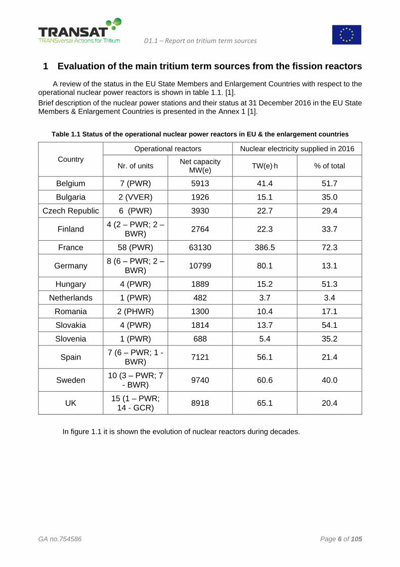
Table 1.1 Status of the operational nuclear power reactors in EU & the enlargement countries
Country
Operational reactors Nuclear electricity supplied in 2016
Nr. of units Net capacity MW(e) TW(e).h % of total
Belgium 7 (PWR) 5913 41.4 51.7
Bulgaria 2 (VVER) 1926 15.1 35.0
Czech Republic 6 (PWR) 3930 22.7 29.4
Finland 4 (2 – PWR; 2 – BWR) 2764 22.3 33.7
France 58 (PWR) 63130 386.5 72.3
Germany 8 (6 – PWR; 2 – BWR) 10799 80.1 13.1
Hungary 4 (PWR) 1889 15.2 51.3
Netherlands 1 (PWR) 482 3.7 3.4
Romania 2 (PHWR) 1300 10.4 17.1
Slovakia 4 (PWR) 1814 13.7 54.1
Slovenia 1 (PWR) 688 5.4 35.2
Spain 7 (6 – PWR; 1 - BWR) 7121 56.1 21.4
Sweden 10 (3 – PWR; 7 - BWR) 9740 60.6 40.0
UK 15 (1 – PWR; 14 - GCR) 8918 65.1 20.4
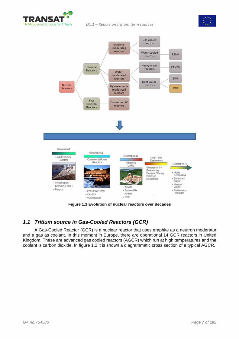
In figure 1.1 it is shown the evolution of nuclear reactors during decades.
D1.1 – Report on tritium term sources
GA no.754586 Page 7 of 105
Figure 1.1 Evolution of nuclear reactors over decades
1.1 Tritium source in Gas-Cooled Reactors (GCR) A Gas-Cooled Reactor (GCR) is a nuclear reactor that uses graphite as a neutron moderator
and a gas as coolant. In this moment in Europe, there are operational 14 GCR reactors in United Kingdom. These are advanced gas cooled reactors (AGCR) which run at high temperatures and the coolant is carbon dioxide. In figure 1.2 it is shown a diagrammatic cross section of a typical AGCR.
D1.1 – Report on tritium term sources
GA no.754586 Page 8 of 105
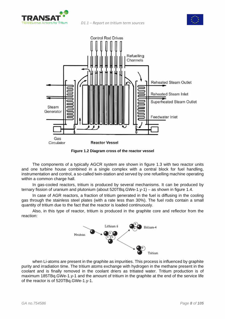
Figure 1.2 Diagram cross of the reactor vessel
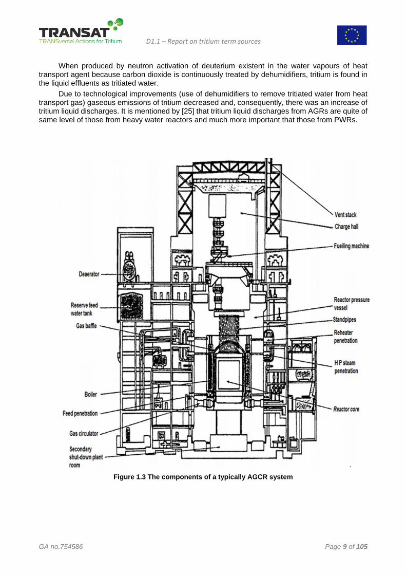
The components of a typically AGCR system are shown in figure 1.3 with two reactor units and one turbine house combined in a single complex with a central block for fuel handling, instrumentation and control, a so-called twin-station and served by one refuelling machine operating within a common charge hall.
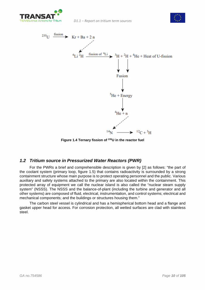
In gas-cooled reactors, tritium is produced by several mechanisms. It can be produced by ternary fission of uranium and plutonium (about 520TBq.GWe-1.y-1) – as shown in figure 1.4.
In case of AGR reactors, a fraction of tritium generated in the fuel is diffusing in the cooling gas through the stainless steel plates (with a rate less than 30%). The fuel rods contain a small quantity of tritium due to the fact that the reactor is loaded continuously.
Also, in this type of reactor, tritium is produced in the graphite core and reflector from the reaction:
when Li-atoms are present in the graphite as impurities. This process is influenced by graphite
purity and irradiation time. The tritium atoms exchange with hydrogen in the methane present in the coolant and is finally removed in the coolant driers as tritiated water. Tritium production is of maximum 185TBq.GWe-1.y-1 and the amount of tritium in the graphite at the end of the service life of the reactor is of 520TBq.GWe-1.y-1.
D1.1 – Report on tritium term sources
GA no.754586 Page 9 of 105
When produced by neutron activation of deuterium existent in the water vapours of heat transport agent because carbon dioxide is continuously treated by dehumidifiers, tritium is found in the liquid effluents as tritiated water.
Due to technological improvements (use of dehumidifiers to remove tritiated water from heat transport gas) gaseous emissions of tritium decreased and, consequently, there was an increase of tritium liquid discharges. It is mentioned by [25] that tritium liquid discharges from AGRs are quite of same level of those from heavy water reactors and much more important that those from PWRs.
Figure 1.3 The components of a typically AGCR system
D1.1 – Report on tritium term sources
GA no.754586 Page 10 of 105
Figure 1.4 Ternary fission of 235U in the reactor fuel
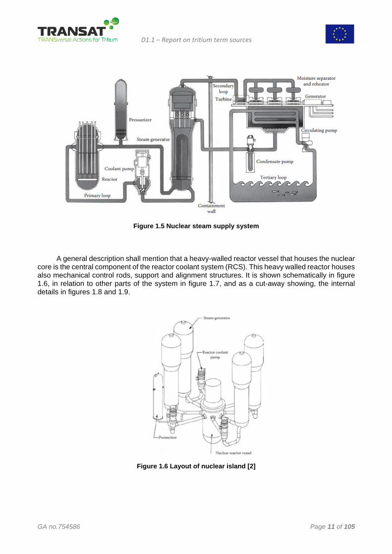
1.2 Tritium source in Pressurized Water Reactors (PWR) For the PWRs a brief and comprehensible description is given by [2] as follows: “the part of
the coolant system (primary loop, figure 1.5) that contains radioactivity is surrounded by a strong containment structure whose main purpose is to protect operating personnel and the public. Various auxiliary and safety systems attached to the primary are also located within the containment. This protected array of equipment we call the nuclear island is also called the “nuclear steam supply system” (NSSS). The NSSS and the balance-of-plant (including the turbine and generator and all other systems) are composed of fluid, electrical, instrumentation, and control systems; electrical and mechanical components; and the buildings or structures housing them.”
The carbon steel vessel is cylindrical and has a hemispherical bottom head and a flange and gasket upper head for access. For corrosion protection, all wetted surfaces are clad with stainless steel.
D1.1 – Report on tritium term sources
GA no.754586 Page 11 of 105
Figure 1.5 Nuclear steam supply system
A general description shall mention that a heavy-walled reactor vessel that houses the nuclear
core is the central component of the reactor coolant system (RCS). This heavy walled reactor houses also mechanical control rods, support and alignment structures. It is shown schematically in figure 1.6, in relation to other parts of the system in figure 1.7, and as a cut-away showing, the internal details in figures 1.8 and 1.9.
Figure 1.6 Layout of nuclear island [2]
D1.1 – Report on tritium term sources
GA no.754586 Page 12 of 105
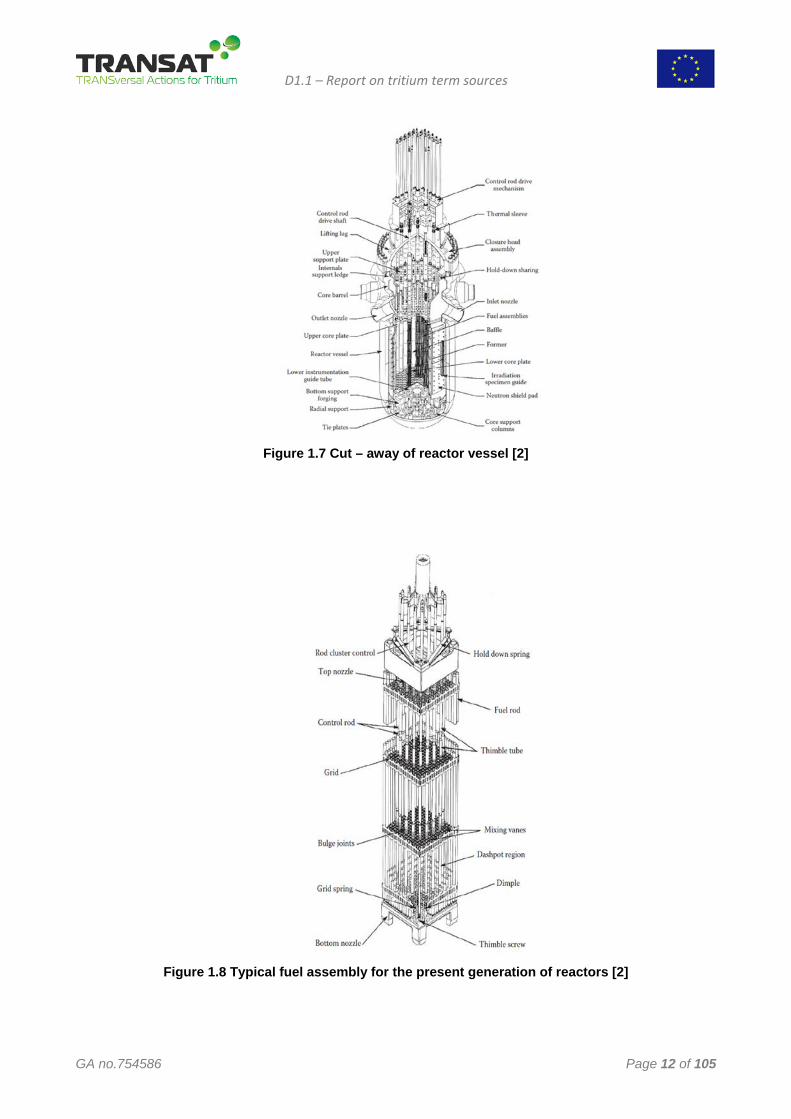
Figure 1.7 Cut – away of reactor vessel [2]
Figure 1.8 Typical fuel assembly for the present generation of reactors [2]
D1.1 – Report on tritium term sources
GA no.754586 Page 13 of 105
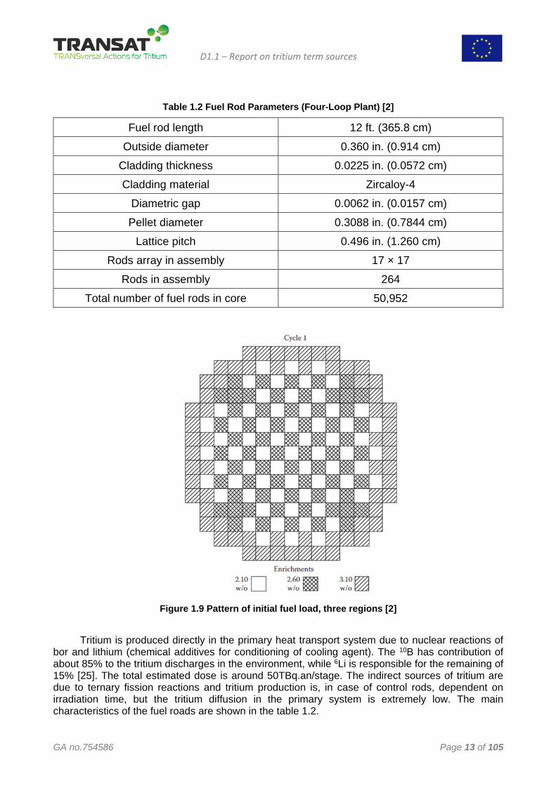
Table 1.2 Fuel Rod Parameters (Four-Loop Plant) [2]
Fuel rod length 12 ft. (365.8 cm) Outside diameter 0.360 in. (0.914 cm)
Cladding thickness 0.0225 in. (0.0572 cm) Cladding material Zircaloy-4
Diametric gap 0.0062 in. (0.0157 cm) Pellet diameter 0.3088 in. (0.7844 cm)
Lattice pitch 0.496 in. (1.260 cm) Rods array in assembly 17 × 17
Rods in assembly 264
Total number of fuel rods in core 50,952
Figure 1.9 Pattern of initial fuel load, three regions [2]
Tritium is produced directly in the primary heat transport system due to nuclear reactions of
bor and lithium (chemical additives for conditioning of cooling agent). The 10B has contribution of about 85% to the tritium discharges in the environment, while 6Li is responsible for the remaining of 15% [25]. The total estimated dose is around 50TBq.an/stage. The indirect sources of tritium are due to ternary fission reactions and tritium production is, in case of control rods, dependent on irradiation time, but the tritium diffusion in the primary system is extremely low. The main characteristics of the fuel roads are shown in the table 1.2.
D1.1 – Report on tritium term sources
GA no.754586 Page 14 of 105
The production of tritium is around 520 TBq/GWe.an due to fuel fission reaction but most of it is trapped in fuel elements. For this reason, tritium is released in the primary agent just in case of cladding failure (manufacturing defects, fatigue or impurities).
On average per reactor, annual liquid discharges of tritium are approximately 10 TBq for the 900 MWe plateau with a maximum of 15 TBq. The activity released by gas is approximately 0.3 TBq/stage for 900 MWe. Around 98% of the tritium produced in 2007 on the entire EDF stations were released in liquid form [25].
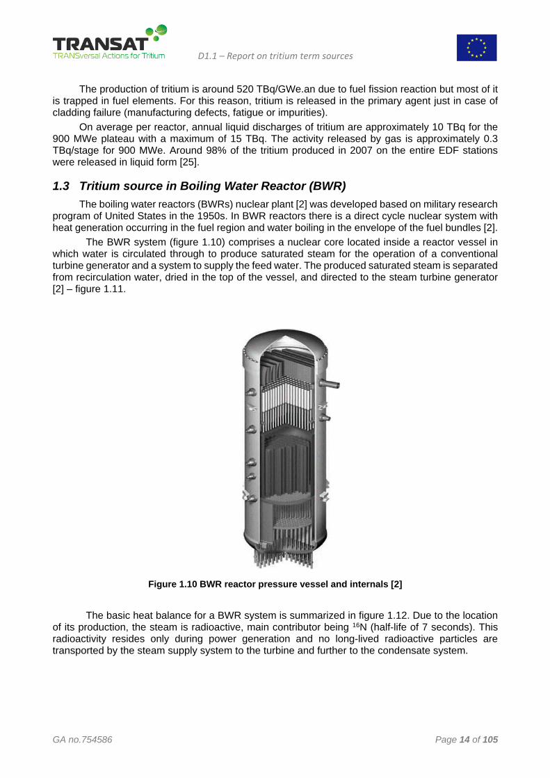
1.3 Tritium source in Boiling Water Reactor (BWR) The boiling water reactors (BWRs) nuclear plant [2] was developed based on military research
program of United States in the 1950s. In BWR reactors there is a direct cycle nuclear system with heat generation occurring in the fuel region and water boiling in the envelope of the fuel bundles [2]. The BWR system (figure 1.10) comprises a nuclear core located inside a reactor vessel in which water is circulated through to produce saturated steam for the operation of a conventional turbine generator and a system to supply the feed water. The produced saturated steam is separated from recirculation water, dried in the top of the vessel, and directed to the steam turbine generator [2] – figure 1.11.
Figure 1.10 BWR reactor pressure vessel and internals [2]
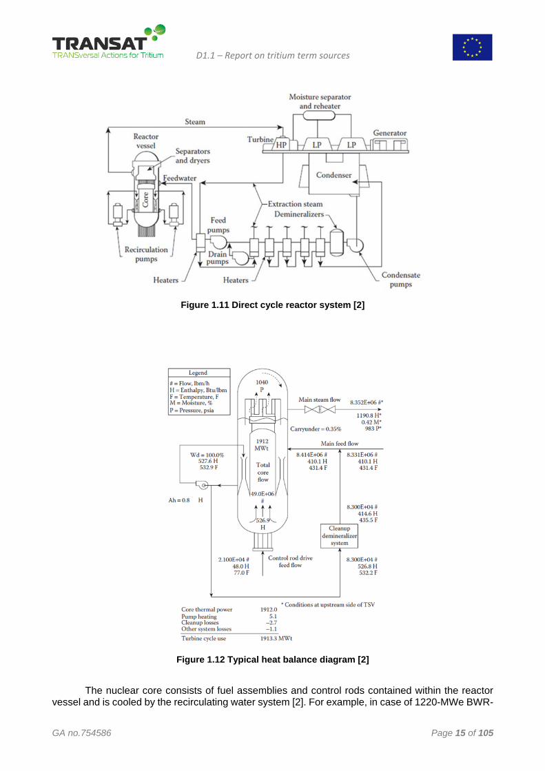
The basic heat balance for a BWR system is summarized in figure 1.12. Due to the location of its production, the steam is radioactive, main contributor being 16N (half-life of 7 seconds). This radioactivity resides only during power generation and no long-lived radioactive particles are transported by the steam supply system to the turbine and further to the condensate system.
D1.1 – Report on tritium term sources
GA no.754586 Page 15 of 105
Figure 1.11 Direct cycle reactor system [2]
Figure 1.12 Typical heat balance diagram [2]
The nuclear core consists of fuel assemblies and control rods contained within the reactor
vessel and is cooled by the recirculating water system [2]. For example, in case of 1220-MWe BWR-
D1.1 – Report on tritium term sources
GA no.754586 Page 16 of 105
6 there are 748 fuel assemblies and 177 control rod assemblies (core array: ~ 4.9 m diameter; 4.3 m high). The BWR operates at constant pressure and consequently maintains a constant steam pressure. The following auxiliary systems are used for normal operation of the nuclear plant:
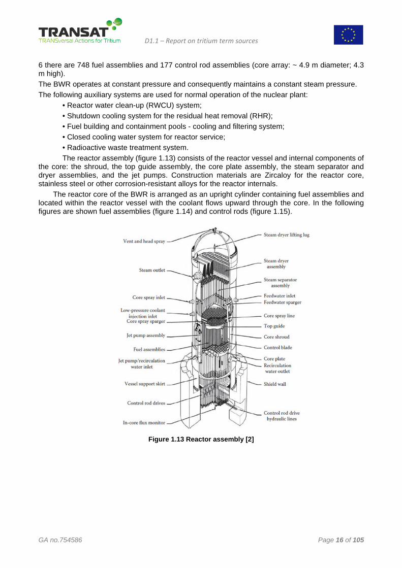
• Reactor water clean-up (RWCU) system; • Shutdown cooling system for the residual heat removal (RHR); • Fuel building and containment pools - cooling and filtering system; • Closed cooling water system for reactor service; • Radioactive waste treatment system. The reactor assembly (figure 1.13) consists of the reactor vessel and internal components of
the core: the shroud, the top guide assembly, the core plate assembly, the steam separator and dryer assemblies, and the jet pumps. Construction materials are Zircaloy for the reactor core, stainless steel or other corrosion-resistant alloys for the reactor internals.
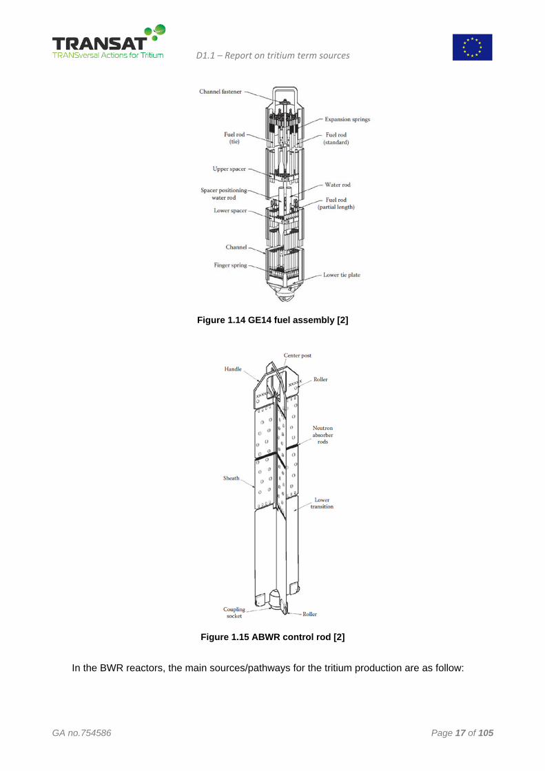
The reactor core of the BWR is arranged as an upright cylinder containing fuel assemblies and located within the reactor vessel with the coolant flows upward through the core. In the following figures are shown fuel assemblies (figure 1.14) and control rods (figure 1.15).
Figure 1.13 Reactor assembly [2]
D1.1 – Report on tritium term sources
GA no.754586 Page 17 of 105
Figure 1.14 GE14 fuel assembly [2]
Figure 1.15 ABWR control rod [2]
In the BWR reactors, the main sources/pathways for the tritium production are as follow:
D1.1 – Report on tritium term sources
GA no.754586 Page 18 of 105
• The ternary fission of U and Pu in the fuel that is of the order of 520 TBq/(GWe.year)). Part of the tritium produced diffuse in the sheaths fuel (Zircaloy-2), where mostly is stopped by the layer of external oxide;
• Cladding defects (less than 1% of the quantity of tritium formed in the fuel); • Neutron activation of naturally occurring deuterium in the primary heat transport system (very
low production); • Tritium production in control rods, sheathed in stainless steel, but with small contribution by
diffusion in the primary heat transport system. For all the BWR reactors, the release values for liquid and gaseous tritium vary from 2.1 to
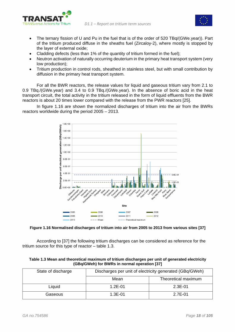
0.9 TBq./(GWe.year) and 3.4 to 0.9 TBq./(GWe.year). In the absence of boric acid in the heat transport circuit, the total activity in the tritium released in the form of liquid effluents from the BWR reactors is about 20 times lower compared with the release from the PWR reactors [25]. In figure 1.16 are shown the normalized discharges of tritium into the air from the BWRs reactors worldwide during the period 2005 – 2013.
Figure 1.16 Normalised discharges of tritium into air from 2005 to 2013 from various sites [37]
According to [37] the following tritium discharges can be considered as reference for the
tritium source for this type of reactor – table 1.3.
Table 1.3 Mean and theoretical maximum of tritium discharges per unit of generated electricity (GBq/GWeh) for BWRs in normal operation [37]
State of discharge Discharges per unit of electricity generated (GBq/GWeh)
Mean Theoretical maximum
Liquid 1.2E-01 2.3E-01
Gaseous 1.3E-01 2.7E-01
D1.1 – Report on tritium term sources
GA no.754586 Page 19 of 105
1.4 Tritium source in Heavy water reactors (HWR) Tritium was produced until 1988 in special heavy water reactors at the Savannah River site
mainly for the military program. In this type of reactors the heavy water is used as neutron moderator and reactor coolant because the light water has a large absorption cross section for thermal neutrons. The maximum values of the elastic scattering (σscattering) and absorption cross sections (σabsorption), in the energy range 0.1eV to 0.1 MeV, for the main isotopes used as moderator are:
11H : σscattering = 18 barn; σabsorption = 0.17 barn 12D : σscattering = 3.4 barn; σabsorption = 0.00025 barn 612C : σscattering = 4.6 barn; σabsorption = 0.0016 barn Neutron absorption (even small) by the deuterium atoms in heavy water will directly produce
tritium (T or 3H). Consequently, the coolant and the moderator will be contaminated with tritium, even in the absence of particulate or ionic impurities.
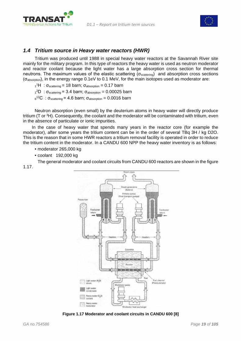
In the case of heavy water that spends many years in the reactor core (for example the moderator), after some years the tritium content can be in the order of several TBq 3H / kg D2O. This is the reason that in some HWR reactors a tritium removal facility is operated in order to reduce the tritium content in the moderator. In a CANDU 600 NPP the heavy water inventory is as follows:
• moderator 265,000 kg • coolant 192,000 kg
The general moderator and coolant circuits from CANDU 600 reactors are shown in the figure 1.17.
Figure 1.17 Moderator and coolant circuits in CANDU 600 [8]
D1.1 – Report on tritium term sources
GA no.754586 Page 20 of 105
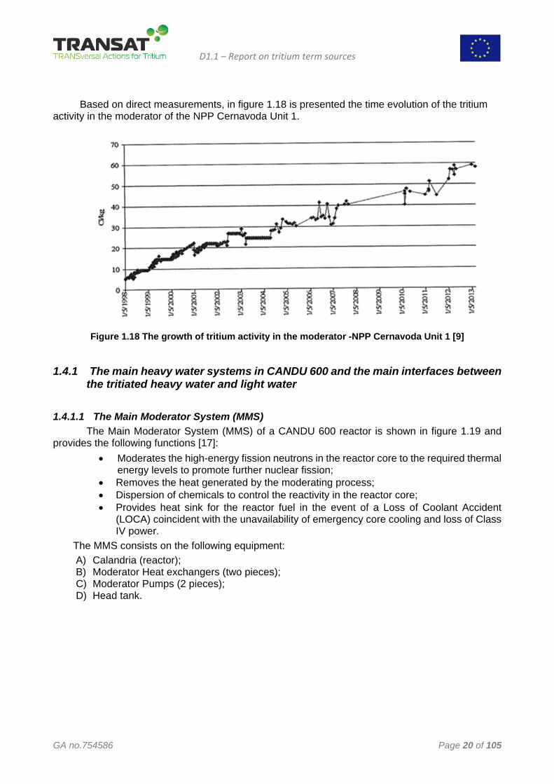
Based on direct measurements, in figure 1.18 is presented the time evolution of the tritium
activity in the moderator of the NPP Cernavoda Unit 1.
Figure 1.18 The growth of tritium activity in the moderator -NPP Cernavoda Unit 1 [9]
1.4.1 The main heavy water systems in CANDU 600 and the main interfaces between the tritiated heavy water and light water
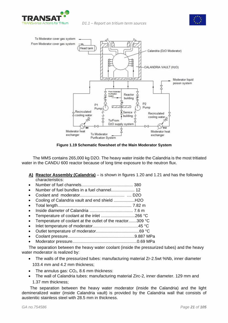
1.4.1.1 The Main Moderator System (MMS) The Main Moderator System (MMS) of a CANDU 600 reactor is shown in figure 1.19 and provides the following functions [17]:
• Moderates the high-energy fission neutrons in the reactor core to the required thermal energy levels to promote further nuclear fission;
• Removes the heat generated by the moderating process; • Dispersion of chemicals to control the reactivity in the reactor core; • Provides heat sink for the reactor fuel in the event of a Loss of Coolant Accident
(LOCA) coincident with the unavailability of emergency core cooling and loss of Class IV power.
The MMS consists on the following equipment: A) Calandria (reactor); B) Moderator Heat exchangers (two pieces); C) Moderator Pumps (2 pieces); D) Head tank.
D1.1 – Report on tritium term sources
GA no.754586 Page 21 of 105
Figure 1.19 Schematic flowsheet of the Main Moderator System
The MMS contains 265,000 kg D2O. The heavy water inside the Calandria is the most tritiated
water in the CANDU 600 reactor because of long time exposure to the neutron flux.
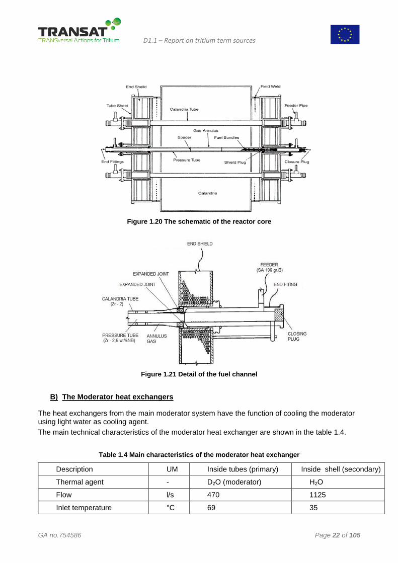
A) Reactor Assembly (Calandria) – is shown in figures 1.20 and 1.21 and has the following characteristics:
• Number of fuel channels............................................ 380 • Number of fuel bundles in a fuel channel.................... 12 • Coolant and moderator...................................... .... D2O • Cooling of Calandria vault and end shield ..................H2O • Total length............................................................... 7.82 m • Inside diameter of Calandria ..................................... 7.6 m • Temperature of coolant at the inlet .............................266 °C • Temperature of coolant at the outlet of the reactor.......309 °C • Inlet temperature of moderator.......................................45 °C • Outlet temperature of moderator.....................................69 °C • Coolant pressure.........................................................9.887 MPa • Moderator pressure.......................................................0.69 MPa The separation between the heavy water coolant (inside the pressurized tubes) and the heavy
water moderator is realized by: • The walls of the pressurized tubes: manufacturing material Zr-2.5wt %Nb, inner diameter 103.4 mm and 4.2 mm thickness; • The annulus gas: CO2, 8.6 mm thickness: • The wall of Calandria tubes: manufacturing material Zirc-2, inner diameter. 129 mm and 1.37 mm thickness; The separation between the heavy water moderator (inside the Calandria) and the light
demineralized water (inside Calandria vault) is provided by the Calandria wall that consists of austenitic stainless steel with 28.5 mm in thickness.
D1.1 – Report on tritium term sources
GA no.754586 Page 22 of 105
Figure 1.20 The schematic of the reactor core
Figure 1.21 Detail of the fuel channel
B) The Moderator heat exchangers
The heat exchangers from the main moderator system have the function of cooling the moderator using light water as cooling agent. The main technical characteristics of the moderator heat exchanger are shown in the table 1.4.
Table 1.4 Main characteristics of the moderator heat exchanger
Description UM Inside tubes (primary) Inside shell (secondary)
Thermal agent - D2O (moderator) H2O
Flow l/s 470 1125
Inlet temperature °C 69 35
D1.1 – Report on tritium term sources
GA no.754586 Page 23 of 105
Outlet temperature °C 49 47.9
Operational pressure MPa 0.69 0.69
Tube material - INCOLOY 800 Carbon steel
Tube dimensions mm Outside diameter= 15.9 Wall thickness =1.13
-
Total surface for heat transfer m2 1478
Total volume m3 4.85 14.8
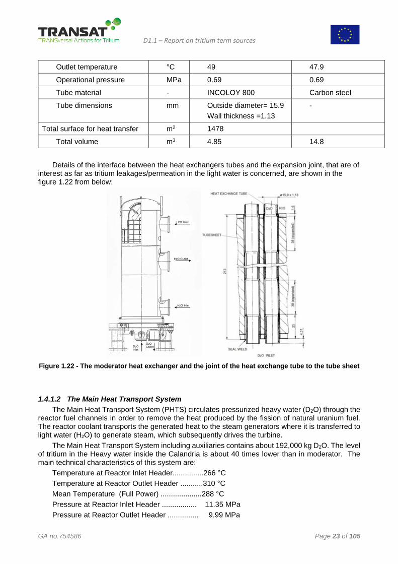
Details of the interface between the heat exchangers tubes and the expansion joint, that are of
interest as far as tritium leakages/permeation in the light water is concerned, are shown in the figure 1.22 from below:
Figure 1.22 - The moderator heat exchanger and the joint of the heat exchange tube to the tube sheet
1.4.1.2 The Main Heat Transport System The Main Heat Transport System (PHTS) circulates pressurized heavy water (D2O) through the
reactor fuel channels in order to remove the heat produced by the fission of natural uranium fuel. The reactor coolant transports the generated heat to the steam generators where it is transferred to light water (H2O) to generate steam, which subsequently drives the turbine.
The Main Heat Transport System including auxiliaries contains about 192,000 kg D2O. The level of tritium in the Heavy water inside the Calandria is about 40 times lower than in moderator. The main technical characteristics of this system are:
Temperature at Reactor Inlet Header...............266 °C Temperature at Reactor Outlet Header ...........310 °C Mean Temperature (Full Power) ....................288 °C Pressure at Reactor Inlet Header ................. 11.35 MPa Pressure at Reactor Outlet Header ............... 9.99 MPa
D1.1 – Report on tritium term sources
GA no.754586 Page 24 of 105
Maximum Channel flow ................................. 24 kg/s Total Core flow.....................................................7.7 Mg/s D2O volumes Steam generator heat exchange tubes.............. 38.94 m3 Steam Generator Inlet Head ...............................4.94 m3 Steam Generator Outlet Head .............................4.94 m3 Pump Suction Piping ......................................... 2.75 m3 Pump ................................................................. 1.95 m3 Pump Discharge Piping ......................................1.95 m3 Inlet Headers ..................................................... 2.68 m3 Inlet Feeders .......................................................8.67 m3 Inlet End Fittings................................................. 9.26m3 Fuel Channels .....................................................7.82 m3 Outlet End Fittings ...............................................9.26 m3 Outlet Feeders.....................................................18.97 m3 Outlet Headers .....................................................3.4 m3 Steam generator inlet piping................................4.64 m3 TOTAL volume of .............................................120.2 m3 The Main Heat Transport System contains the following equipment: - 380 Fuel channels - 4 Steam generators - 4 Main Pumps - 4 Inlet headers - 4 Outlet headers The equipment that has an interface between the tritiated heavy water and light water is the
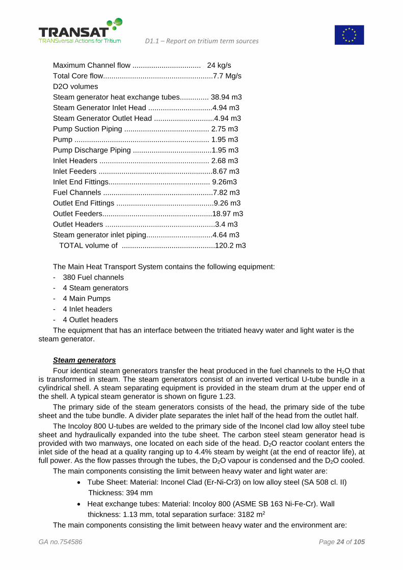
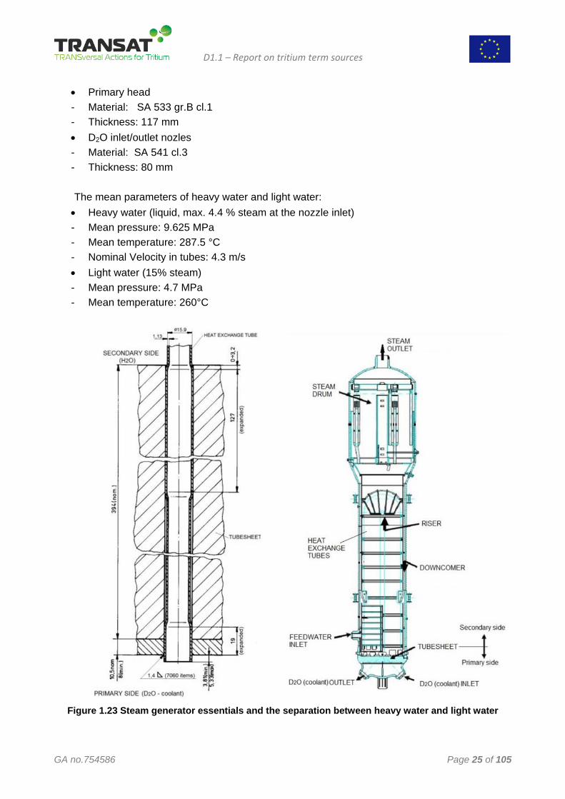
steam generator. Steam generators Four identical steam generators transfer the heat produced in the fuel channels to the H2O that
is transformed in steam. The steam generators consist of an inverted vertical U-tube bundle in a cylindrical shell. A steam separating equipment is provided in the steam drum at the upper end of the shell. A typical steam generator is shown on figure 1.23.
The primary side of the steam generators consists of the head, the primary side of the tube sheet and the tube bundle. A divider plate separates the inlet half of the head from the outlet half.
The Incoloy 800 U-tubes are welded to the primary side of the Inconel clad low alloy steel tube sheet and hydraulically expanded into the tube sheet. The carbon steel steam generator head is provided with two manways, one located on each side of the head. D2O reactor coolant enters the inlet side of the head at a quality ranging up to 4.4% steam by weight (at the end of reactor life), at full power. As the flow passes through the tubes, the D2O vapour is condensed and the D2O cooled.
The main components consisting the limit between heavy water and light water are: • Tube Sheet: Material: Inconel Clad (Er-Ni-Cr3) on low alloy steel (SA 508 cl. II)
Thickness: 394 mm • Heat exchange tubes: Material: Incoloy 800 (ASME SB 163 Ni-Fe-Cr). Wall thickness: 1.13 mm, total separation surface: 3182 m2
The main components consisting the limit between heavy water and the environment are:
D1.1 – Report on tritium term sources
GA no.754586 Page 25 of 105
• Primary head - Material: SA 533 gr.B cl.1 - Thickness: 117 mm • D2O inlet/outlet nozles - Material: SA 541 cl.3 - Thickness: 80 mm
The mean parameters of heavy water and light water: • Heavy water (liquid, max. 4.4 % steam at the nozzle inlet) - Mean pressure: 9.625 MPa - Mean temperature: 287.5 °C - Nominal Velocity in tubes: 4.3 m/s • Light water (15% steam) - Mean pressure: 4.7 MPa - Mean temperature: 260°C
Figure 1.23 Steam generator essentials and the separation between heavy water and light water

D1.1 – Report on tritium term sources
GA no.754586 Page 26 of 105
1.4.2 The main barriers against tritium release The barriers against tritium release are presented based on the consideration that most of the tritium is produced in the moderator. Therefore, in order to avoid tritium emissions in the environment, some barriers are provided between heavy water (containing tritium) and light water used as coolant. There are four main general barriers against tritium release:
A) Reactor barriers B) Heat exchangers and recirculated cooling water barriers C) Steam generator & main condenser barriers D) Containment/technological barriers
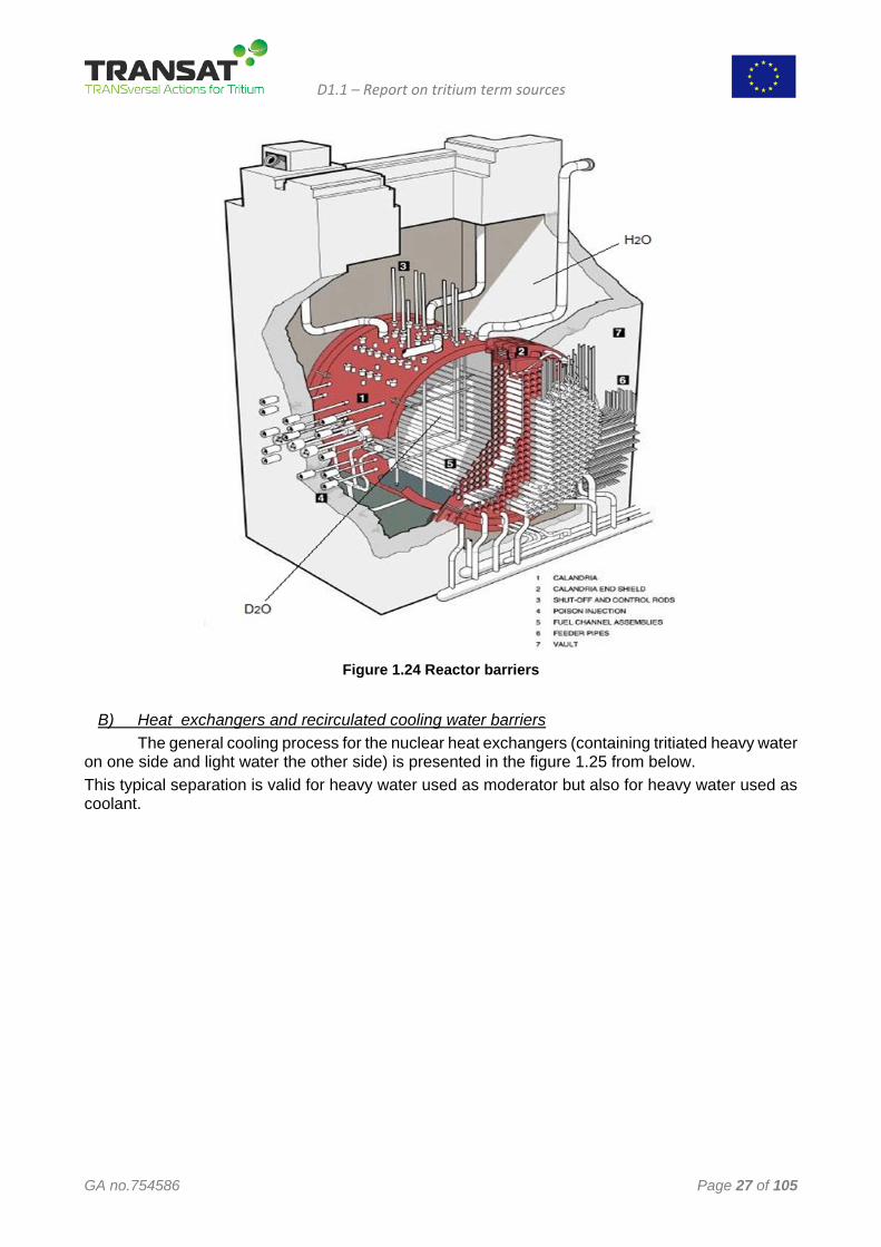
A. Reactor barriers Details of the reactor barriers provided with the main scope to avoid releasing of tritiated water inside the containment are shown in the figure 1.24.
• Inside the reactor, the pressurized tubes (containing D2O-coolant) are separated from D2O-moderator by 4 mm material Zr-2.5wt %Nb (pressure tube wall thickness) plus the annulus gas (CO2; 8.6 mm thickness) plus the wall of Calandria tubes (material Zirc-2; 1.37 mm thickness);
• Outside of reactor the heavy water coolant is transported inside feeders and pipes (minimum thickness about 3 mm, fabricated from carbon steel - SA 106 gr. B);
• Calandria wall (minimum thickness 9 mm material SA 240 type 304L); • Calandria vault (1.22 m thickness, material concrete); • Between Calandria wall and Calandria vault the space is full of light water; • The moderator is cooled with light water.
D1.1 – Report on tritium term sources
GA no.754586 Page 27 of 105
Figure 1.24 Reactor barriers
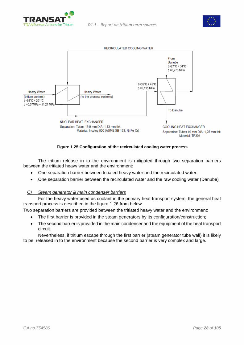
B) Heat exchangers and recirculated cooling water barriers The general cooling process for the nuclear heat exchangers (containing tritiated heavy water on one side and light water the other side) is presented in the figure 1.25 from below. This typical separation is valid for heavy water used as moderator but also for heavy water used as coolant.
D1.1 – Report on tritium term sources
GA no.754586 Page 28 of 105
Figure 1.25 Configuration of the recirculated cooling water process
The tritium release in to the environment is mitigated through two separation barriers between the tritiated heavy water and the environment:
• One separation barrier between tritiated heavy water and the recirculated water; • One separation barrier between the recirculated water and the raw cooling water (Danube)
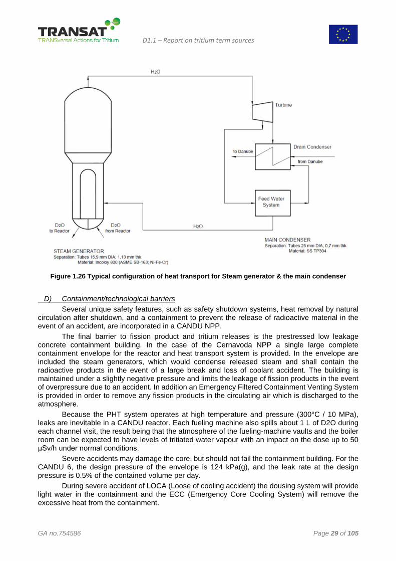
C) Steam generator & main condenser barriers For the heavy water used as coolant in the primary heat transport system, the general heat transport process is described in the figure 1.26 from below. Two separation barriers are provided between the tritiated heavy water and the environment:
• The first barrier is provided in the steam generators by its configuration/construction; • The second barrier is provided in the main condenser and the equipment of the heat transport
circuit. Nevertheless, if tritium escape through the first barrier (steam generator tube wall) it is likely to be released in to the environment because the second barrier is very complex and large.
D1.1 – Report on tritium term sources
GA no.754586 Page 29 of 105
Figure 1.26 Typical configuration of heat transport for Steam generator & the main condenser
D) Containment/technological barriers Several unique safety features, such as safety shutdown systems, heat removal by natural circulation after shutdown, and a containment to prevent the release of radioactive material in the event of an accident, are incorporated in a CANDU NPP. The final barrier to fission product and tritium releases is the prestressed low leakage concrete containment building. In the case of the Cernavoda NPP a single large complete containment envelope for the reactor and heat transport system is provided. In the envelope are included the steam generators, which would condense released steam and shall contain the radioactive products in the event of a large break and loss of coolant accident. The building is maintained under a slightly negative pressure and limits the leakage of fission products in the event of overpressure due to an accident. In addition an Emergency Filtered Containment Venting System is provided in order to remove any fission products in the circulating air which is discharged to the atmosphere. Because the PHT system operates at high temperature and pressure (300°C / 10 MPa), leaks are inevitable in a CANDU reactor. Each fueling machine also spills about 1 L of D2O during each channel visit, the result being that the atmosphere of the fueling-machine vaults and the boiler room can be expected to have levels of tritiated water vapour with an impact on the dose up to 50 μSv/h under normal conditions. Severe accidents may damage the core, but should not fail the containment building. For the CANDU 6, the design pressure of the envelope is 124 kPa(g), and the leak rate at the design pressure is 0.5% of the contained volume per day. During severe accident of LOCA (Loose of cooling accident) the dousing system will provide light water in the containment and the ECC (Emergency Core Cooling System) will remove the excessive heat from the containment.
D1.1 – Report on tritium term sources
GA no.754586 Page 30 of 105
1.4.3 Assessment of tritium emissions during accidents A simplified Event sequence during a severe accident is presented below.
• A large HTS pipe break is postulated to occur instantaneously. • Steam discharges to containment, causing a rise in containment pressure and temperature,
the pressure in primary heat transport drops rapidly. • The reactor power rises quickly due to the positive void coefficient, causing a rapid
increase in fuel and sheath temperatures. • The reactor is shut down by either shutdown system (~2 sec). • Containment ventilation paths are isolated. • The fluid inventory in the channels decreases and flow remains low, so that fuel and fuel
sheaths continue to rise in temperature. Some fuel sheaths may fail. Hydrogen, deuterium and tritium concentrations inside the containment increase.
• Containment dousing is initiated and starts to reduce containment pressure. • ECC injection is signaled at about 20 seconds. Valves on the gas tanks open to drive water
from the accumulator tanks into the HTS (or high-pressure ECC pumps start). • Steam generator rapid cooldown is also initiated automatically, and the steam is discharged
to atmosphere. • Fuel temperatures stabilize and fall as the headers, and then the channels, refill. • After the initial high pressure injection phase, ECC switches to medium-pressure and then
to low pressure in which the water from the break is recovered from the building sumps, cooled, and re-injected. This gives a stable end-state which can last for months.
Hydrogen and tritium can build up in containment after an accident. After a LOCA, hydrogen is formed slowly by radiolysis of the heavy and light water circulating through the core. A severe accident such as a LOCA plus loss of emergency core cooling can also produce hydrogen because of the chemical reaction between the hot fuel sheaths and the steam in the fuel channels. The containment building promotes some mixing of hydrogen due to natural circulation. Air cooler fans provide forced mixing.
In order to have information about hydrogen concentrations inside the containment in Cernavoda NPP was installed a Reactor Building Hydrogen Monitoring System. In addition, Passive autocatalytic recombiners (PAR) are used for long-term hydrogen control. They present a catalyst bed to the containment atmosphere, on which the hydrogen recombines with oxygen. The heat of reaction causes a convection flow through the device, which helps mix the containment atmosphere.
1.4.4 Impact of defects in barriers on tritium release The defects in the barriers have a significant impact on their role to mitigate the tritium release into the environment. The most relevant defects on this matter concerning the CANDU 6 reactor are presented below.
1. Delayed hydride cracking (DHC) The most common form of hydrogen damage in the reactor systems is the degradation of hydride forming materials, in particular the zirconium alloys. In reactors, generally these make up the fuel cladding, but in CANDUs they also make up the pressure tubes and the Calandria tubes. Delayed hydride cracking (DHC) and hydride blistering are responsible for the major replacements of CANDU pressure tubes in the past. The most prone locations are at the rolled joint areas on each end of the pressurized tubes due to the increased deuterium production and migration rate at the galvanic couple between the

D1.1 – Report on tritium term sources
GA no.754586 Page 31 of 105
pressure tube and the stainless steel end-fitting. The deuterium produced through corrosion of the stainless steel is free to migrate into the pressurized tubes due to the intimate contact resulting from the rolled-joint seal. Residual stress due to the rolling process also plays a large role in these locations.
2. Heat exchangers tube wall defects During operation, in all the heat exchangers tube walls (including steam generators) may appear defects. The transfers of tritium from the tritiated heavy water in to the light water can appear only when the tube walls break. The walls of tubes are periodically examined using eddy current method and those with defects may be plugged before the breaks occur. The following main defect types have been identified:
• Denting • Fretting • Wastage • Wall thinning • Intergranular attack and stress corrosion cracking • Due to fatigue
3. Breaks of pipes transporting tritiated heavy water
The heavy water is circulated through pipelines manufactured from carbon steel or stainless steel. When a pipeline breaks, this is a severe accident and tritium is released into the containment. Consequently tritium emissions in atmosphere can appear.
D1.1 – Report on tritium term sources
GA no.754586 Page 32 of 105
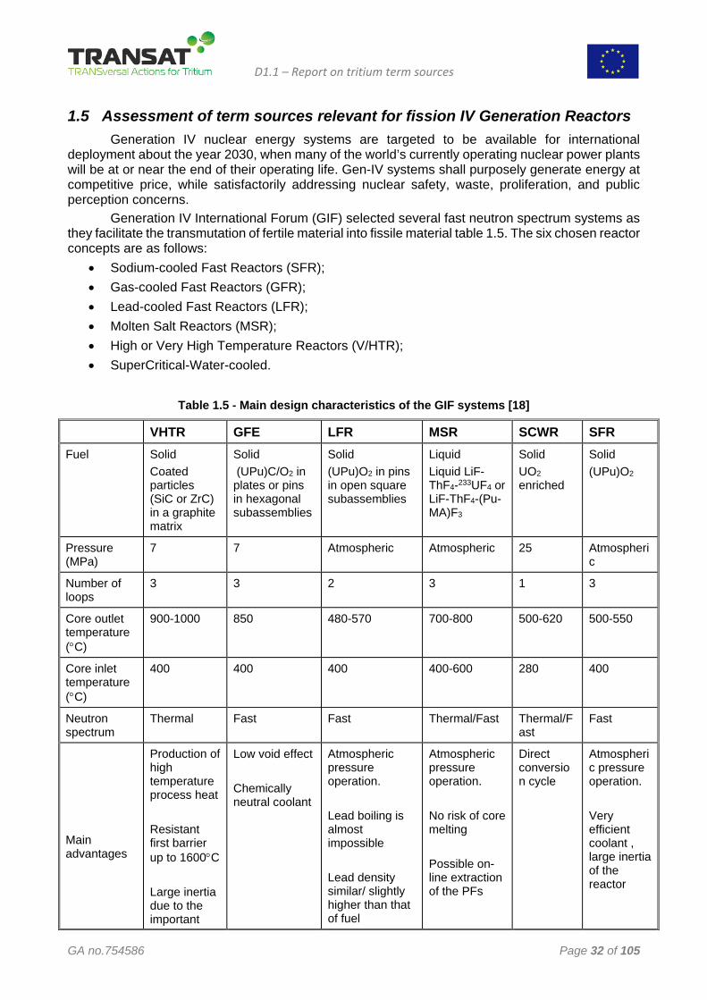
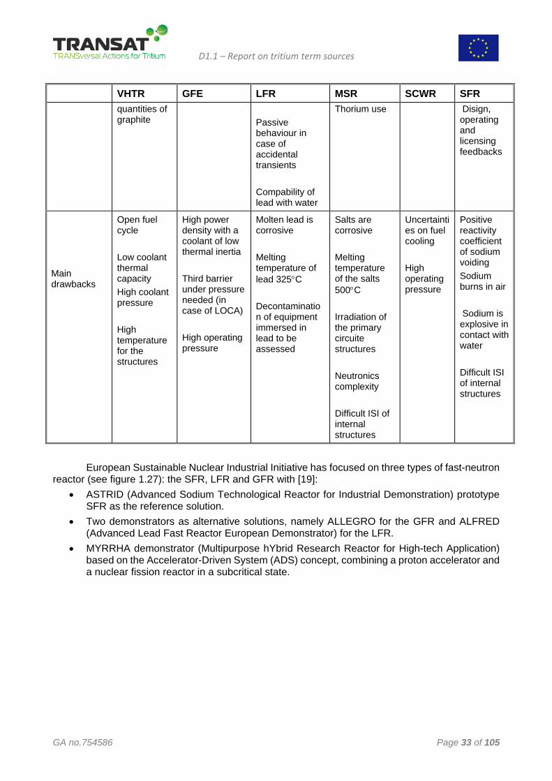
1.5 Assessment of term sources relevant for fission IV Generation Reactors Generation IV nuclear energy systems are targeted to be available for international deployment about the year 2030, when many of the world’s currently operating nuclear power plants will be at or near the end of their operating life. Gen-IV systems shall purposely generate energy at competitive price, while satisfactorily addressing nuclear safety, waste, proliferation, and public perception concerns. Generation IV International Forum (GIF) selected several fast neutron spectrum systems as they facilitate the transmutation of fertile material into fissile material table 1.5. The six chosen reactor concepts are as follows:
• Sodium-cooled Fast Reactors (SFR); • Gas-cooled Fast Reactors (GFR); • Lead-cooled Fast Reactors (LFR); • Molten Salt Reactors (MSR); • High or Very High Temperature Reactors (V/HTR); • SuperCritical-Water-cooled.
Table 1.5 - Main design characteristics of the GIF systems [18]
VHTR GFE LFR MSR SCWR SFR Fuel Solid
Coated particles (SiC or ZrC) in a graphite matrix
Solid (UPu)C/O2 in plates or pins in hexagonal subassemblies
Solid (UPu)O2 in pins in open square subassemblies
Liquid Liquid LiF-ThF4-233UF4 or LiF-ThF4-(Pu-MA)F3
Solid UO2 enriched
Solid (UPu)O2
Pressure (MPa)
7 7 Atmospheric Atmospheric 25 Atmospheric
Number of loops
3 3 2 3 1 3
Core outlet temperature (°C)
900-1000 850 480-570 700-800 500-620 500-550
Core inlet temperature (°C)
400 400 400 400-600 280 400
Neutron spectrum
Thermal Fast Fast Thermal/Fast Thermal/Fast
Fast
Main advantages
Production of high temperature process heat Resistant first barrier up to 1600°C Large inertia due to the important
Low void effect Chemically neutral coolant
Atmospheric pressure operation. Lead boiling is almost impossible Lead density similar/ slightly higher than that of fuel
Atmospheric pressure operation. No risk of core melting Possible on-line extraction of the PFs
Direct conversion cycle
Atmospheric pressure operation. Very efficient coolant , large inertia of the reactor
D1.1 – Report on tritium term sources
GA no.754586 Page 33 of 105
VHTR GFE LFR MSR SCWR SFR quantities of graphite
Passive behaviour in case of accidental transients Compability of lead with water
Thorium use
Disign, operating and licensing feedbacks
Main drawbacks
Open fuel cycle Low coolant thermal capacity High coolant pressure High temperature for the structures
High power density with a coolant of low thermal inertia Third barrier under pressure needed (in case of LOCA) High operating pressure
Molten lead is corrosive Melting temperature of lead 325°C Decontamination of equipment immersed in lead to be assessed
Salts are corrosive Melting temperature of the salts 500°C Irradiation of the primary circuite structures Neutronics complexity Difficult ISI of internal structures
Uncertainties on fuel cooling High operating pressure
Positive reactivity coefficient of sodium voiding Sodium burns in air Sodium is explosive in contact with water Difficult ISI of internal structures
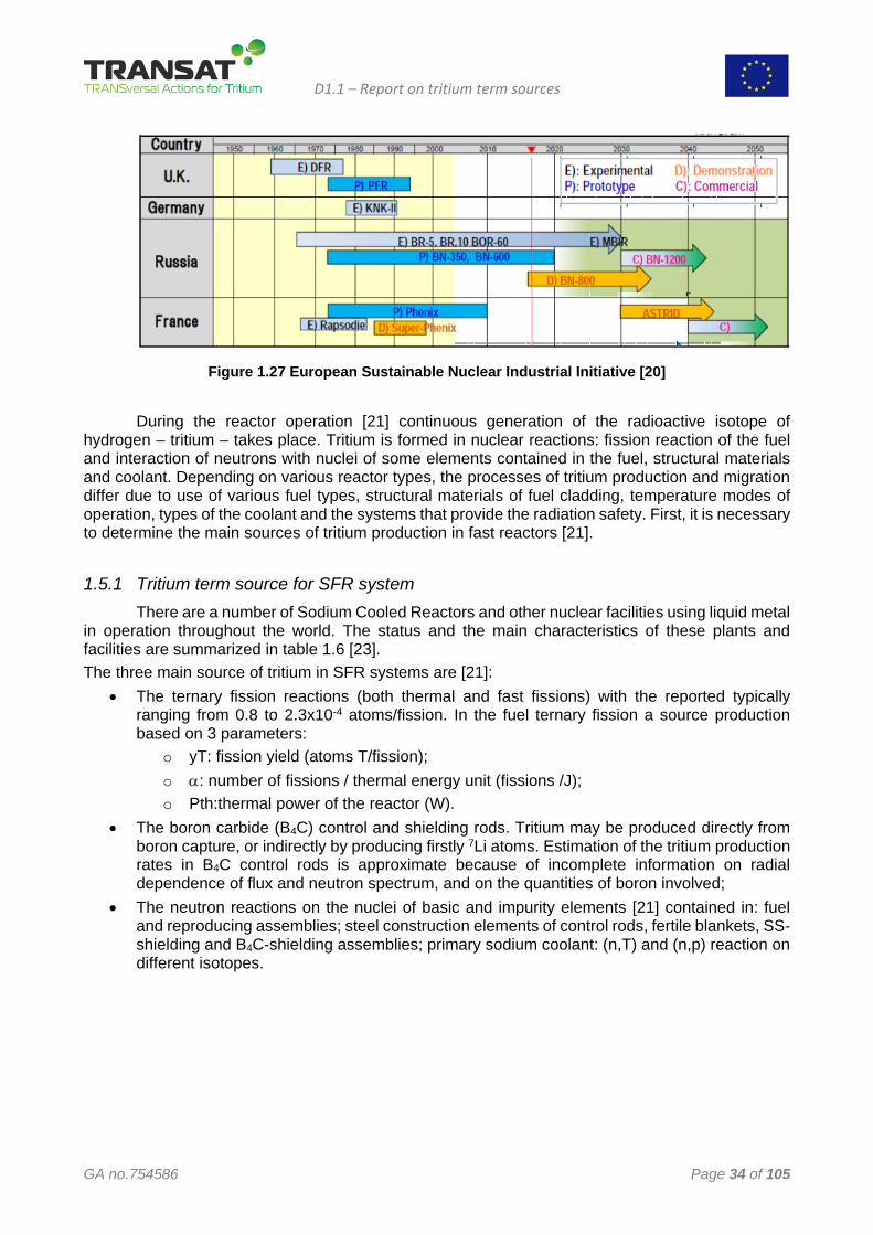
European Sustainable Nuclear Industrial Initiative has focused on three types of fast-neutron reactor (see figure 1.27): the SFR, LFR and GFR with [19]:
• ASTRID (Advanced Sodium Technological Reactor for Industrial Demonstration) prototype SFR as the reference solution.
• Two demonstrators as alternative solutions, namely ALLEGRO for the GFR and ALFRED (Advanced Lead Fast Reactor European Demonstrator) for the LFR.
• MYRRHA demonstrator (Multipurpose hYbrid Research Reactor for High-tech Application) based on the Accelerator-Driven System (ADS) concept, combining a proton accelerator and a nuclear fission reactor in a subcritical state.
D1.1 – Report on tritium term sources
GA no.754586 Page 34 of 105
Figure 1.27 European Sustainable Nuclear Industrial Initiative [20]
During the reactor operation [21] continuous generation of the radioactive isotope of
hydrogen – tritium – takes place. Tritium is formed in nuclear reactions: fission reaction of the fuel and interaction of neutrons with nuclei of some elements contained in the fuel, structural materials and coolant. Depending on various reactor types, the processes of tritium production and migration differ due to use of various fuel types, structural materials of fuel cladding, temperature modes of operation, types of the coolant and the systems that provide the radiation safety. First, it is necessary to determine the main sources of tritium production in fast reactors [21].
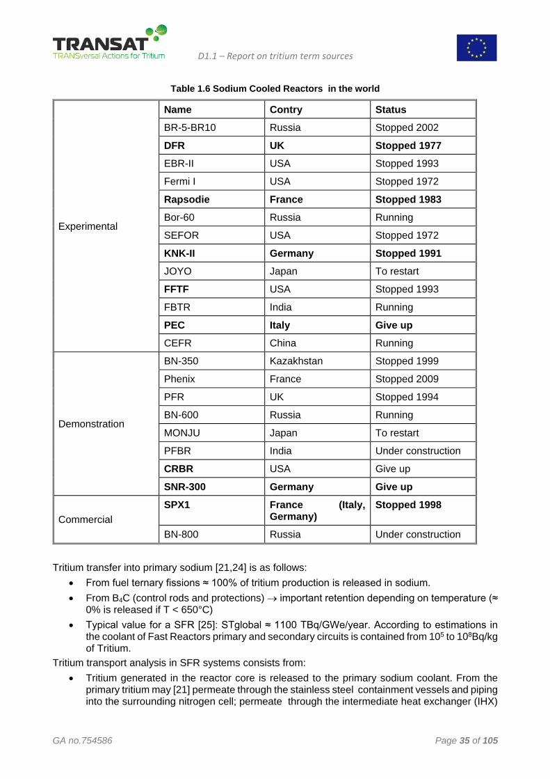
1.5.1 Tritium term source for SFR system There are a number of Sodium Cooled Reactors and other nuclear facilities using liquid metal in operation throughout the world. The status and the main characteristics of these plants and facilities are summarized in table 1.6 [23]. The three main source of tritium in SFR systems are [21]:
• The ternary fission reactions (both thermal and fast fissions) with the reported typically ranging from 0.8 to 2.3x10⁻⁴ atoms/fission. In the fuel ternary fission a source production based on 3 parameters:
o yT: fission yield (atoms T/fission); o α: number of fissions / thermal energy unit (fissions /J); o Pth:thermal power of the reactor (W).
• The boron carbide (B4C) control and shielding rods. Tritium may be produced directly from boron capture, or indirectly by producing firstly 7Li atoms. Estimation of the tritium production rates in B4C control rods is approximate because of incomplete information on radial dependence of flux and neutron spectrum, and on the quantities of boron involved;
• The neutron reactions on the nuclei of basic and impurity elements [21] contained in: fuel and reproducing assemblies; steel construction elements of control rods, fertile blankets, SS-shielding and B4C-shielding assemblies; primary sodium coolant: (n,T) and (n,p) reaction on different isotopes.
D1.1 – Report on tritium term sources
GA no.754586 Page 35 of 105
Table 1.6 Sodium Cooled Reactors in the world
Experimental
Name Contry Status BR-5-BR10 Russia Stopped 2002
DFR UK Stopped 1977 EBR-II USA Stopped 1993
Fermi I USA Stopped 1972
Rapsodie France Stopped 1983 Bor-60 Russia Running
SEFOR USA Stopped 1972
KNK-II Germany Stopped 1991 JOYO Japan To restart
FFTF USA Stopped 1993
FBTR India Running
PEC Italy Give up CEFR China Running
Demonstration
BN-350 Kazakhstan Stopped 1999
Phenix France Stopped 2009
PFR UK Stopped 1994
BN-600 Russia Running
MONJU Japan To restart
PFBR India Under construction
CRBR USA Give up
SNR-300 Germany Give up
Commercial SPX1 France (Italy,
Germany) Stopped 1998
BN-800 Russia Under construction
Tritium transfer into primary sodium [21,24] is as follows:
• From fuel ternary fissions ≈ 100% of tritium production is released in sodium. • From B4C (control rods and protections) → important retention depending on temperature (≈
0% is released if T < 650°C) • Typical value for a SFR [25]: STglobal ≈ 1100 TBq/GWe/year. According to estimations in
the coolant of Fast Reactors primary and secondary circuits is contained from 105 to 108Bq/kg of Tritium.
Tritium transport analysis in SFR systems consists from: • Tritium generated in the reactor core is released to the primary sodium coolant. From the
primary tritium may [21] permeate through the stainless steel containment vessels and piping into the surrounding nitrogen cell; permeate through the intermediate heat exchanger (IHX)
D1.1 – Report on tritium term sources
GA no.754586 Page 36 of 105
tubes into the secondary circuit; be removed by the primary cold trap; decay naturally to 3He; escape by leakage from the primary cover gas
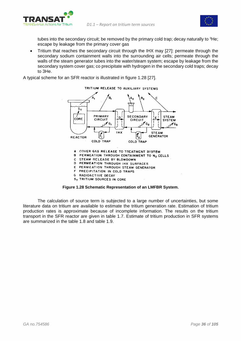
• Tritium that reaches the secondary circuit through the IHX may [27]: permeate through the secondary sodium containment walls into the surrounding air cells; permeate through the walls of the steam generator tubes into the water/steam system; escape by leakage from the secondary system cover gas; co precipitate with hydrogen in the secondary cold traps; decay to 3He.
A typical scheme for an SFR reactor is illustrated in figure 1.28 [27].
Figure 1.28 Schematic Representation of an LMFBR System.
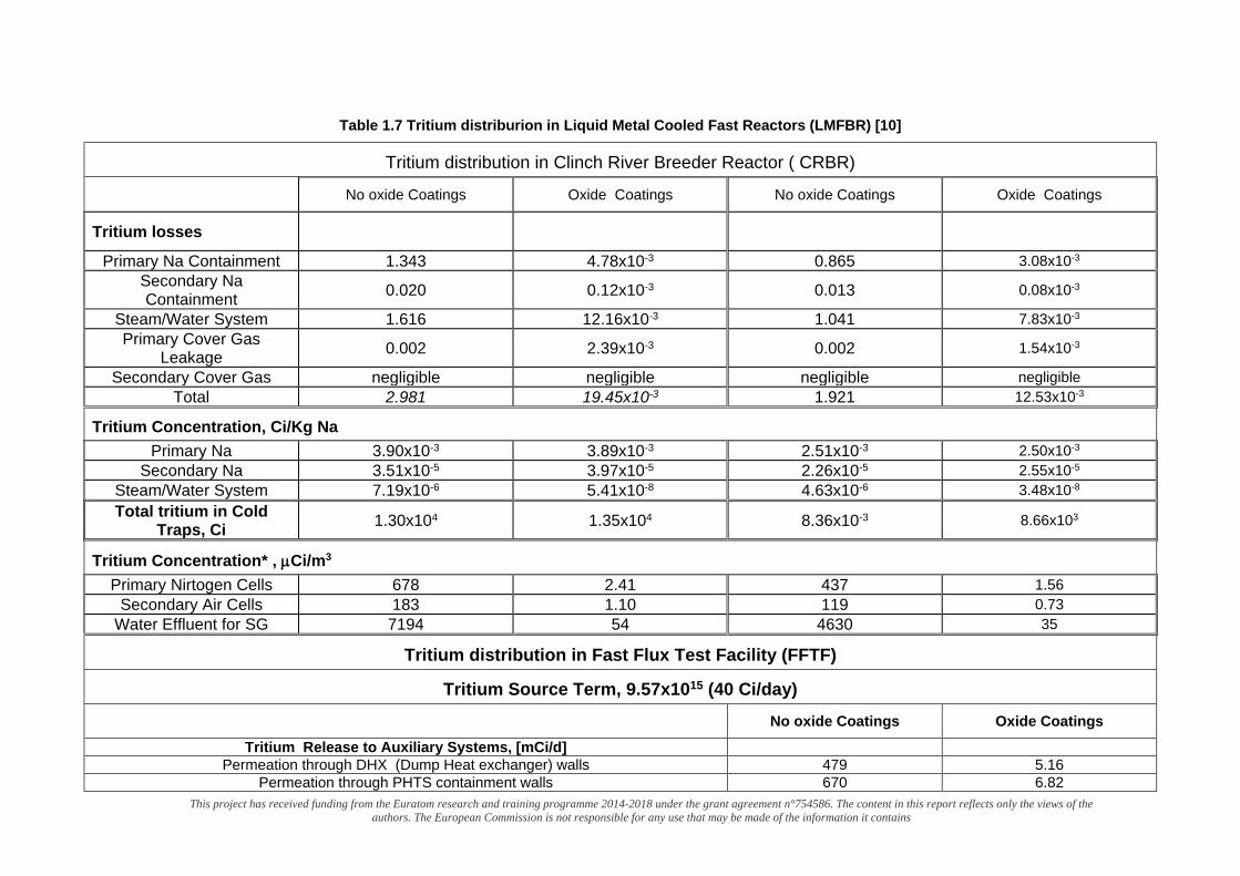
The calculation of source term is subjected to a large number of uncertainties, but some literature data on tritium are available to estimate the tritium generation rate. Estimation of tritium production rates is approximate because of incomplete information. The results on the tritium transport in the SFR reactor are given in table 1.7. Estimate of tritium production in SFR systems are summarized in the table 1.8 and table 1.9.
This project has received funding from the Euratom research and training programme 2014-2018 under the grant agreement n°754586. The content in this report reflects only the views of the authors. The European Commission is not responsible for any use that may be made of the information it contains
Table 1.7 Tritium distriburion in Liquid Metal Cooled Fast Reactors (LMFBR) [10]
Tritium distribution in Clinch River Breeder Reactor ( CRBR)
No oxide Coatings Oxide Coatings No oxide Coatings Oxide Coatings
Tritium losses
Primary Na Containment 1.343 4.78x10⁻³ 0.865 3.08x10⁻³ Secondary Na Containment 0.020 0.12x10⁻³ 0.013 0.08x10⁻³
Steam/Water System 1.616 12.16x10⁻³ 1.041 7.83x10⁻³ Primary Cover Gas
Leakage 0.002 2.39x10⁻³ 0.002 1.54x10⁻³
Secondary Cover Gas negligible negligible negligible negligible Total 2.981 19.45x10⁻³ 1.921 12.53x10⁻³
Tritium Concentration, Ci/Kg Na Primary Na 3.90x10⁻³ 3.89x10⁻³ 2.51x10⁻³ 2.50x10⁻³
Secondary Na 3.51x10⁻⁵ 3.97x10⁻⁵ 2.26x10⁻⁵ 2.55x10⁻⁵
Steam/Water System 7.19x10⁻⁶ 5.41x10⁻⁸ 4.63x10⁻⁶ 3.48x10⁻⁸
Total tritium in Cold Traps, Ci 1.30x10⁴ 1.35x10⁴ 8.36x10⁻³ 8.66x10³
Tritium Concentration* , µCi/m3 Primary Nirtogen Cells 678 2.41 437 1.56
Secondary Air Cells 183 1.10 119 0.73 Water Effluent for SG 7194 54 4630 35
Tritium distribution in Fast Flux Test Facility (FFTF)
Tritium Source Term, 9.57x10¹⁵ (40 Ci/day)
No oxide Coatings Oxide Coatings Tritium Release to Auxiliary Systems, [mCi/d]
Permeation through DHX (Dump Heat exchanger) walls 479 5.16 Permeation through PHTS containment walls 670 6.82
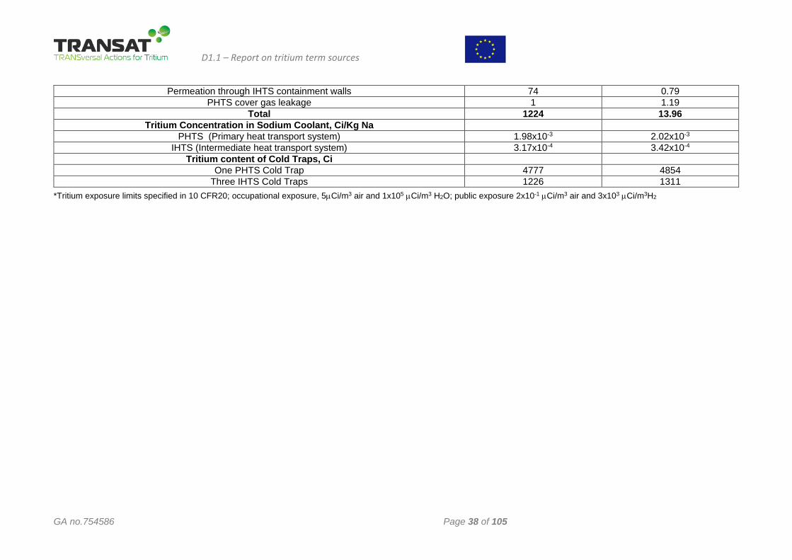
D1.1 – Report on tritium term sources
GA no.754586 Page 38 of 105
Permeation through IHTS containment walls 74 0.79 PHTS cover gas leakage 1 1.19
Total 1224 13.96 Tritium Concentration in Sodium Coolant, Ci/Kg Na
PHTS (Primary heat transport system) 1.98x10⁻³ 2.02x10⁻³
IHTS (Intermediate heat transport system) 3.17x10⁻⁴ 3.42x10⁻⁴
Tritium content of Cold Traps, Ci One PHTS Cold Trap 4777 4854
Three IHTS Cold Traps 1226 1311 *Tritium exposure limits specified in 10 CFR20; occupational exposure, 5µCi/m3 air and 1x10⁵ µCi/m3 H2O; public exposure 2x10⁻¹ µCi/m3 air and 3x10³ µCi/m3H2
This project has received funding from the Euratom research and training programme 2014-2018 under the grant agreement n°754586. The content in this report reflects only the views of the authors. The European Commission is not responsible for any use that may be made of the information it contains
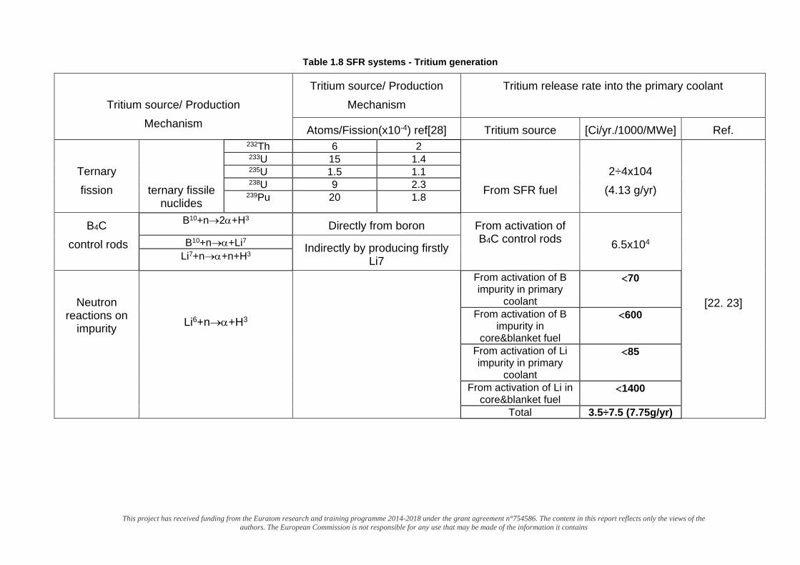
Table 1.8 SFR systems - Tritium generation
Tritium source/ Production
Mechanism
Tritium source/ Production Mechanism
Tritium release rate into the primary coolant
Atoms/Fission(x10-4) ref[28] Tritium source [Ci/yr./1000/MWe] Ref.
Ternary fission
ternary fissile nuclides
232Th 6 2
From SFR fuel
2÷4x10⁴
(4.13 g/yr)
[22. 23]
233U 15 1.4 235U 1.5 1.1 238U 9 2.3
239Pu 20 1.8
B4C control rods
B10+n→2α+H3 Directly from boron From activation of B4C control rods
6.5x10⁴ B10+n→α+Li7 Indirectly by producing firstly
Li7 Li7+n→α+n+H3
Neutron
reactions on impurity
Li6+n→α+H3
From activation of B impurity in primary
coolant
<70
From activation of B impurity in
core&blanket fuel
<600
From activation of Li impurity in primary
coolant
<85
From activation of Li in core&blanket fuel
<1400
Total 3.5÷7.5 (7.75g/yr)
This project has received funding from the Euratom research and training programme 2014-2018 under the grant agreement n°754586. The content in this report reflects only the views of the authors. The European Commission
is not responsible for any use that may be made of the information it contains
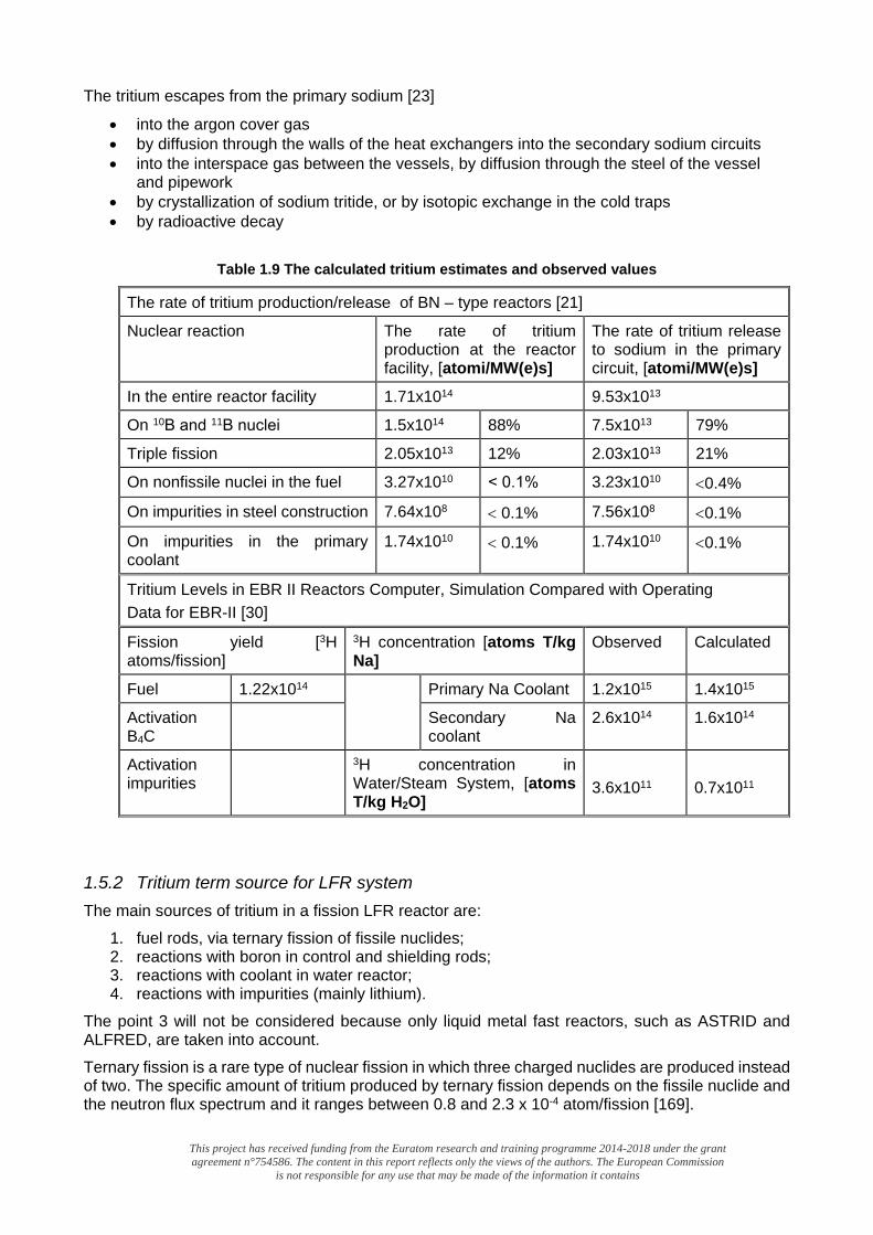
The tritium escapes from the primary sodium [23]
• into the argon cover gas • by diffusion through the walls of the heat exchangers into the secondary sodium circuits • into the interspace gas between the vessels, by diffusion through the steel of the vessel
and pipework • by crystallization of sodium tritide, or by isotopic exchange in the cold traps • by radioactive decay
Table 1.9 The calculated tritium estimates and observed values
The rate of tritium production/release of BN – type reactors [21]
Nuclear reaction The rate of tritium production at the reactor facility, [atomi/MW(e)s]
The rate of tritium release to sodium in the primary circuit, [atomi/MW(e)s]
In the entire reactor facility 1.71x10¹⁴ 9.53x10¹³
On 10В and 11В nuclei 1.5x10¹⁴ 88% 7.5x10¹³ 79%
Triple fission 2.05x10¹³ 12% 2.03x10¹³ 21%
On nonfissile nuclei in the fuel 3.27x10¹⁰ ˂ 0.1% 3.23x10¹⁰ <0.4%
On impurities in steel construction 7.64x10⁸ < 0.1% 7.56x10⁸ <0.1%
On impurities in the primary coolant
1.74x10¹⁰ < 0.1% 1.74x10¹⁰ <0.1%
Tritium Levels in EBR II Reactors Computer, Simulation Compared with Operating Data for EBR-II [30]
Fission yield [3H atoms/fission]
3H concentration [atoms T/kg Na]
Observed Calculated
Fuel 1.22x10¹⁴ Primary Na Coolant 1.2x10¹⁵ 1.4x10¹⁵
Activation B4C
Secondary Na coolant
2.6x10¹⁴ 1.6x10¹⁴
Activation impurities
3H concentration in Water/Steam System, [atoms T/kg H2O]
3.6x10¹¹
0.7x10¹¹
1.5.2 Tritium term source for LFR system The main sources of tritium in a fission LFR reactor are:
1. fuel rods, via ternary fission of fissile nuclides; 2. reactions with boron in control and shielding rods; 3. reactions with coolant in water reactor; 4. reactions with impurities (mainly lithium).
The point 3 will not be considered because only liquid metal fast reactors, such as ASTRID and ALFRED, are taken into account. Ternary fission is a rare type of nuclear fission in which three charged nuclides are produced instead of two. The specific amount of tritium produced by ternary fission depends on the fissile nuclide and the neutron flux spectrum and it ranges between 0.8 and 2.3 x 10⁻⁴ atom/fission [169].
D1.1 – Report on tritium term sources
GA no.754586 Page 41 of 105
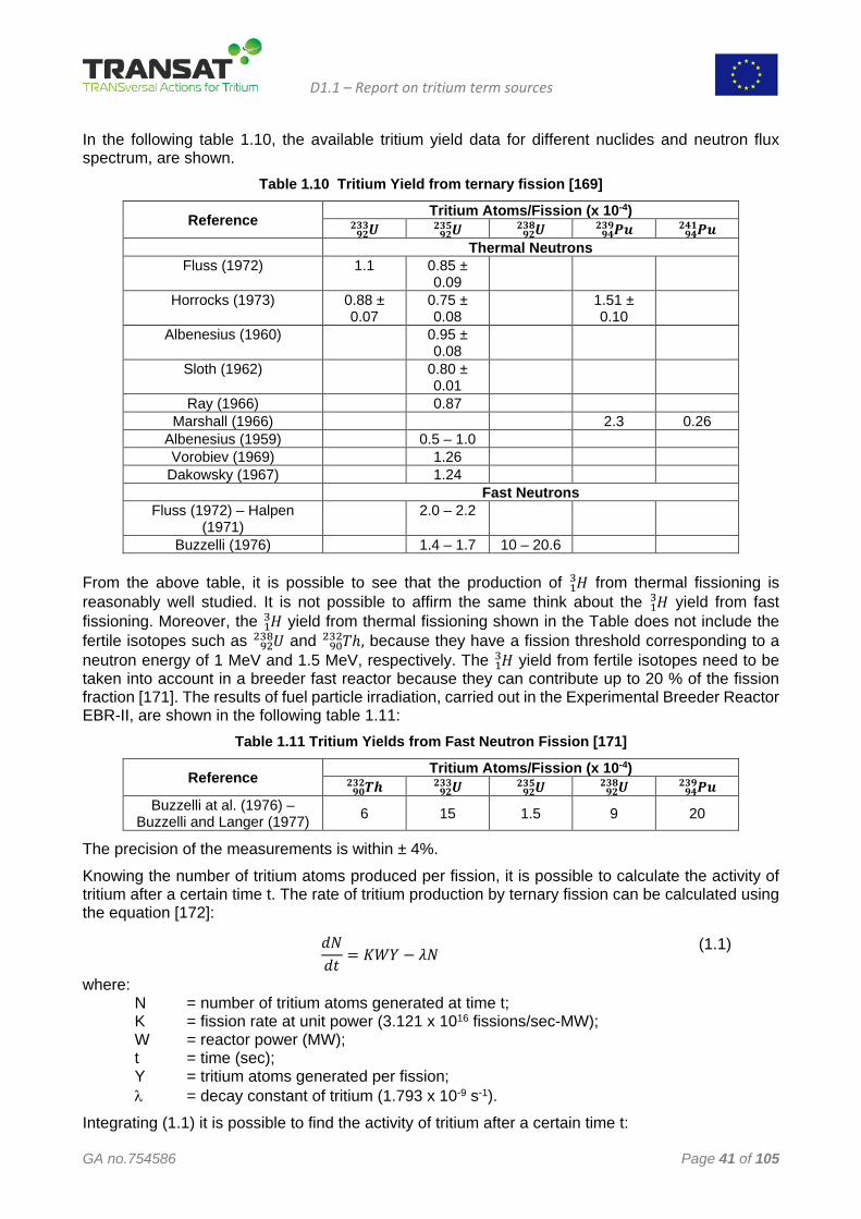
In the following table 1.10, the available tritium yield data for different nuclides and neutron flux spectrum, are shown.
Table 1.10 Tritium Yield from ternary fission [169]
Reference Tritium Atoms/Fission (x 10-4) 𝑼𝑼𝟗𝟗𝟗𝟗
𝟗𝟗𝟐𝟐𝟐𝟐 𝑼𝑼𝟗𝟗𝟗𝟗𝟗𝟗𝟐𝟐𝟐𝟐 𝑼𝑼𝟗𝟗𝟗𝟗
𝟗𝟗𝟐𝟐𝟐𝟐 𝑷𝑷𝑷𝑷𝟗𝟗𝟗𝟗𝟗𝟗𝟐𝟐𝟗𝟗 𝑷𝑷𝑷𝑷𝟗𝟗𝟗𝟗
𝟗𝟗𝟗𝟗𝟐𝟐 Thermal Neutrons
Fluss (1972) 1.1 0.85 ± 0.09
Horrocks (1973) 0.88 ± 0.07
0.75 ± 0.08
1.51 ± 0.10
Albenesius (1960) 0.95 ± 0.08
Sloth (1962) 0.80 ± 0.01
Ray (1966) 0.87 Marshall (1966) 2.3 0.26
Albenesius (1959) 0.5 – 1.0 Vorobiev (1969) 1.26
Dakowsky (1967) 1.24 Fast Neutrons
Fluss (1972) – Halpen (1971)
2.0 – 2.2
Buzzelli (1976) 1.4 – 1.7 10 – 20.6 From the above table, it is possible to see that the production of 𝐻𝐻13 from thermal fissioning is reasonably well studied. It is not possible to affirm the same think about the 𝐻𝐻13 yield from fast fissioning. Moreover, the 𝐻𝐻13 yield from thermal fissioning shown in the Table does not include the fertile isotopes such as 𝑈𝑈92
238 and 𝑇𝑇ℎ90232 , because they have a fission threshold corresponding to a
neutron energy of 1 MeV and 1.5 MeV, respectively. The 𝐻𝐻13 yield from fertile isotopes need to be taken into account in a breeder fast reactor because they can contribute up to 20 % of the fission fraction [171]. The results of fuel particle irradiation, carried out in the Experimental Breeder Reactor EBR-II, are shown in the following table 1.11:
Table 1.11 Tritium Yields from Fast Neutron Fission [171]
Reference Tritium Atoms/Fission (x 10-4) 𝑻𝑻𝑻𝑻𝟗𝟗𝟗𝟗
𝟗𝟗𝟐𝟐𝟗𝟗 𝑼𝑼𝟗𝟗𝟗𝟗𝟗𝟗𝟐𝟐𝟐𝟐 𝑼𝑼𝟗𝟗𝟗𝟗
𝟗𝟗𝟐𝟐𝟐𝟐 𝑼𝑼𝟗𝟗𝟗𝟗𝟗𝟗𝟐𝟐𝟐𝟐 𝑷𝑷𝑷𝑷𝟗𝟗𝟗𝟗
𝟗𝟗𝟐𝟐𝟗𝟗 Buzzelli at al. (1976) –
Buzzelli and Langer (1977) 6 15 1.5 9 20
The precision of the measurements is within ± 4%. Knowing the number of tritium atoms produced per fission, it is possible to calculate the activity of tritium after a certain time t. The rate of tritium production by ternary fission can be calculated using the equation [172]:
𝑑𝑑𝑑𝑑𝑑𝑑𝑑𝑑
= 𝐾𝐾𝐾𝐾𝐾𝐾 − 𝜆𝜆𝑑𝑑 (1.1)
where: N = number of tritium atoms generated at time t; K = fission rate at unit power (3.121 x 10¹⁶ fissions/sec-MW); W = reactor power (MW); t = time (sec); Y = tritium atoms generated per fission; λ = decay constant of tritium (1.793 x 10⁻⁹ s-1).
Integrating (1.1) it is possible to find the activity of tritium after a certain time t:
D1.1 – Report on tritium term sources
GA no.754586 Page 42 of 105
𝐴𝐴 = 𝐾𝐾𝐾𝐾𝐾𝐾�1 − 𝑒𝑒−𝜆𝜆𝜆𝜆� (1.2)
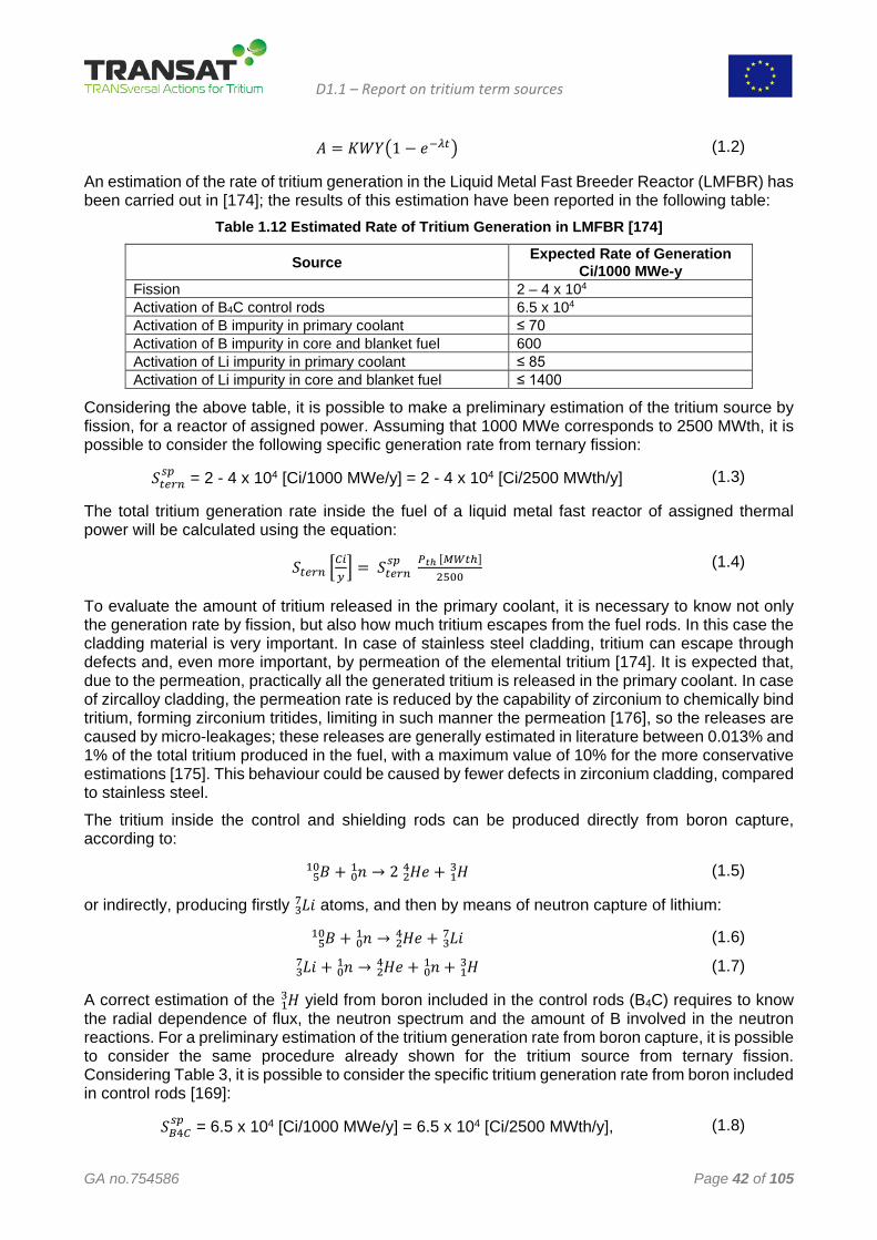
An estimation of the rate of tritium generation in the Liquid Metal Fast Breeder Reactor (LMFBR) has been carried out in [174]; the results of this estimation have been reported in the following table:
Table 1.12 Estimated Rate of Tritium Generation in LMFBR [174]
Source Expected Rate of Generation Ci/1000 MWe-y
Fission 2 – 4 x 10⁴ Activation of B4C control rods 6.5 x 10⁴ Activation of B impurity in primary coolant ≤ 70 Activation of B impurity in core and blanket fuel 600 Activation of Li impurity in primary coolant ≤ 85 Activation of Li impurity in core and blanket fuel ≤ 1400
Considering the above table, it is possible to make a preliminary estimation of the tritium source by fission, for a reactor of assigned power. Assuming that 1000 MWe corresponds to 2500 MWth, it is possible to consider the following specific generation rate from ternary fission:
𝑆𝑆𝜆𝜆𝑡𝑡𝑡𝑡𝑡𝑡𝑠𝑠𝑠𝑠 = 2 - 4 x 10⁴ [Ci/1000 MWe/y] = 2 - 4 x 10⁴ [Ci/2500 MWth/y] (1.3)
The total tritium generation rate inside the fuel of a liquid metal fast reactor of assigned thermal power will be calculated using the equation:
𝑆𝑆𝜆𝜆𝑡𝑡𝑡𝑡𝑡𝑡 �𝐶𝐶𝐶𝐶𝑦𝑦� = 𝑆𝑆𝜆𝜆𝑡𝑡𝑡𝑡𝑡𝑡
𝑠𝑠𝑠𝑠 𝑃𝑃𝑡𝑡ℎ [𝑀𝑀𝑀𝑀𝜆𝜆ℎ]2500
(1.4)
To evaluate the amount of tritium released in the primary coolant, it is necessary to know not only the generation rate by fission, but also how much tritium escapes from the fuel rods. In this case the cladding material is very important. In case of stainless steel cladding, tritium can escape through defects and, even more important, by permeation of the elemental tritium [174]. It is expected that, due to the permeation, practically all the generated tritium is released in the primary coolant. In case of zircalloy cladding, the permeation rate is reduced by the capability of zirconium to chemically bind tritium, forming zirconium tritides, limiting in such manner the permeation [176], so the releases are caused by micro-leakages; these releases are generally estimated in literature between 0.013% and 1% of the total tritium produced in the fuel, with a maximum value of 10% for the more conservative estimations [175]. This behaviour could be caused by fewer defects in zirconium cladding, compared to stainless steel. The tritium inside the control and shielding rods can be produced directly from boron capture, according to:
𝐵𝐵 + 𝑛𝑛01 →510 2 𝐻𝐻𝑒𝑒 + 𝐻𝐻132
4 (1.5)
or indirectly, producing firstly 𝐿𝐿𝐿𝐿37 atoms, and then by means of neutron capture of lithium:
𝐵𝐵 + 𝑛𝑛01 →510 𝐻𝐻𝑒𝑒 + 𝐿𝐿𝐿𝐿3
724 (1.6)
𝐿𝐿𝐿𝐿 + 𝑛𝑛01 →37 𝐻𝐻𝑒𝑒 + 𝑛𝑛01 + 𝐻𝐻132
4 (1.7)
A correct estimation of the 𝐻𝐻13 yield from boron included in the control rods (B4C) requires to know the radial dependence of flux, the neutron spectrum and the amount of B involved in the neutron reactions. For a preliminary estimation of the tritium generation rate from boron capture, it is possible to consider the same procedure already shown for the tritium source from ternary fission. Considering Table 3, it is possible to consider the specific tritium generation rate from boron included in control rods [169]:
𝑆𝑆𝐵𝐵4𝐶𝐶𝑠𝑠𝑠𝑠 = 6.5 x 10⁴ [Ci/1000 MWe/y] = 6.5 x 10⁴ [Ci/2500 MWth/y], (1.8)
D1.1 – Report on tritium term sources
GA no.754586 Page 43 of 105
to evaluate the total tritium generation rate inside the control rods:
𝑆𝑆𝐵𝐵4𝐶𝐶 �𝐶𝐶𝐶𝐶𝑦𝑦� = 𝑆𝑆𝐵𝐵4𝐶𝐶
𝑠𝑠𝑠𝑠 𝑃𝑃𝑡𝑡ℎ [𝑀𝑀𝑀𝑀𝜆𝜆ℎ]2500
(1.9)
From the above equation it would seem that the contribution from reactions with boron to the total tritium released in the primary coolant is dominant; in reality, only 10 – 13% of tritium generated in the control rods is released in the coolant [177]. The remaining part is thought to be chemically or physically trapped inside the control rods. In [169] it is affirmed that the tritium generated by boron reactions is expected to be trapped inside the control rods and not released in the reactor effluents. Lithium, produced by the reaction (1.6), has a relatively high affinity for tritium and it is available for chemical bonding with tritium atoms; this could be a reason of the tritium immobilization inside the control rods. Moreover, internal bubbles, developed in irradiated control rods as the result of helium production, could trap tritium, avoiding the release from the material [178]. The main impurities responsible for the tritium production are the lithium atoms; these atoms react with neutrons according to (1.7) and:
𝐿𝐿𝐿𝐿 + 𝑛𝑛01 →36 𝐻𝐻𝑒𝑒 + 𝐻𝐻132
4 (1.10)
According to Table 1.12, the specific tritium generation rate from lithium impurities could be approximately evaluates as:
𝑆𝑆𝐿𝐿𝐶𝐶𝑠𝑠𝑠𝑠 = 1.5 x 10³ [Ci/1000 MWe/y] = 1.5 x 10³ [Ci/2500 MWth/y], (1.11)
and the total tritium generation rate:
𝑆𝑆𝐿𝐿𝐶𝐶 �𝐶𝐶𝐶𝐶𝑦𝑦� = 𝑆𝑆𝐿𝐿𝐶𝐶
𝑠𝑠𝑠𝑠 𝑃𝑃𝑡𝑡ℎ [𝑀𝑀𝑀𝑀𝜆𝜆ℎ]2500
(1.12)
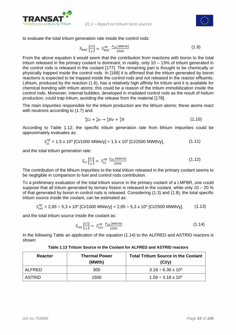
The contribution of the lithium impurities to the total tritium released in the primary coolant seems to be negligible in comparison to fuel and control rods contribution. To a preliminary evaluation of the total tritium source in the primary coolant of a LMFBR, one could suppose that all tritium generated by ternary fission is released in the coolant, while only 10 – 20 % of that generated by boron in control rods is released. Considering (1.3) and (1.8), the total specific tritium source inside the coolant, can be estimated as:
𝑆𝑆𝜆𝜆𝑡𝑡𝜆𝜆𝑠𝑠𝑠𝑠 = 2,65 ÷ 5,3 x 10⁴ [Ci/1000 MWe/y] = 2,65 ÷ 5,3 x 10⁴ [Ci/2500 MWth/y], (1.13)
and the total tritium source inside the coolant as:
𝑆𝑆𝜆𝜆𝑡𝑡𝜆𝜆 �𝐶𝐶𝐶𝐶𝑦𝑦� = 𝑆𝑆𝜆𝜆𝑡𝑡𝜆𝜆
𝑠𝑠𝑠𝑠 𝑃𝑃𝑡𝑡ℎ [𝑀𝑀𝑀𝑀𝜆𝜆ℎ]2500
(1.14)
In the following Table an application of the equation (1.14) to the ALFRED and ASTRID reactors is shown:
Table 1.13 Tritium Source in the Coolant for ALFRED and ASTRID reactors
Reactor Thermal Power (MWth)
Total Tritium Source in the Coolant (Ci/y)
ALFRED 300 3.18 ÷ 6.36 x 10³
ASTRID 1500 1.59 ÷ 3.18 x 10⁴
D1.1 – Report on tritium term sources
GA no.754586 Page 44 of 105
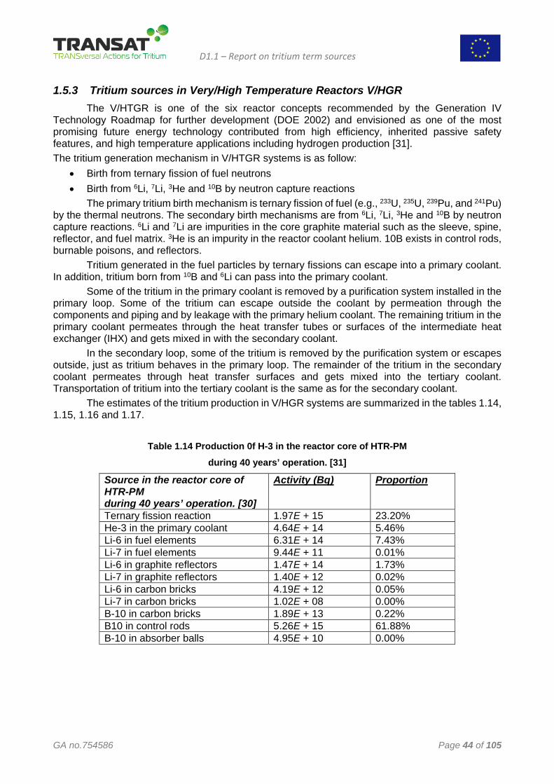
1.5.3 Tritium sources in Very/High Temperature Reactors V/HGR The V/HTGR is one of the six reactor concepts recommended by the Generation IV Technology Roadmap for further development (DOE 2002) and envisioned as one of the most promising future energy technology contributed from high efficiency, inherited passive safety features, and high temperature applications including hydrogen production [31]. The tritium generation mechanism in V/HTGR systems is as follow:
• Birth from ternary fission of fuel neutrons • Birth from 6Li, 7Li, 3He and 10B by neutron capture reactions
The primary tritium birth mechanism is ternary fission of fuel (e.g., 233U, 235U, 239Pu, and 241Pu) by the thermal neutrons. The secondary birth mechanisms are from 6Li, 7Li, 3He and 10B by neutron capture reactions. 6Li and 7Li are impurities in the core graphite material such as the sleeve, spine, reflector, and fuel matrix. 3He is an impurity in the reactor coolant helium. 10B exists in control rods, burnable poisons, and reflectors. Tritium generated in the fuel particles by ternary fissions can escape into a primary coolant. In addition, tritium born from 10B and 6Li can pass into the primary coolant. Some of the tritium in the primary coolant is removed by a purification system installed in the primary loop. Some of the tritium can escape outside the coolant by permeation through the components and piping and by leakage with the primary helium coolant. The remaining tritium in the primary coolant permeates through the heat transfer tubes or surfaces of the intermediate heat exchanger (IHX) and gets mixed in with the secondary coolant. In the secondary loop, some of the tritium is removed by the purification system or escapes outside, just as tritium behaves in the primary loop. The remainder of the tritium in the secondary coolant permeates through heat transfer surfaces and gets mixed into the tertiary coolant. Transportation of tritium into the tertiary coolant is the same as for the secondary coolant. The estimates of the tritium production in V/HGR systems are summarized in the tables 1.14, 1.15, 1.16 and 1.17.
Table 1.14 Production 0f H-3 in the reactor core of HTR-PM during 40 years’ operation. [31]
Source in the reactor core of HTR-PM during 40 years’ operation. [30]
Activity (Bq) Proportion
Ternary fission reaction 1.97E + 15 23.20% He-3 in the primary coolant 4.64E + 14 5.46% Li-6 in fuel elements 6.31E + 14 7.43% Li-7 in fuel elements 9.44E + 11 0.01% Li-6 in graphite reflectors 1.47E + 14 1.73% Li-7 in graphite reflectors 1.40E + 12 0.02% Li-6 in carbon bricks 4.19E + 12 0.05% Li-7 in carbon bricks 1.02E + 08 0.00% B-10 in carbon bricks 1.89E + 13 0.22% B10 in control rods 5.26E + 15 61.88% B-10 in absorber balls 4.95E + 10 0.00%
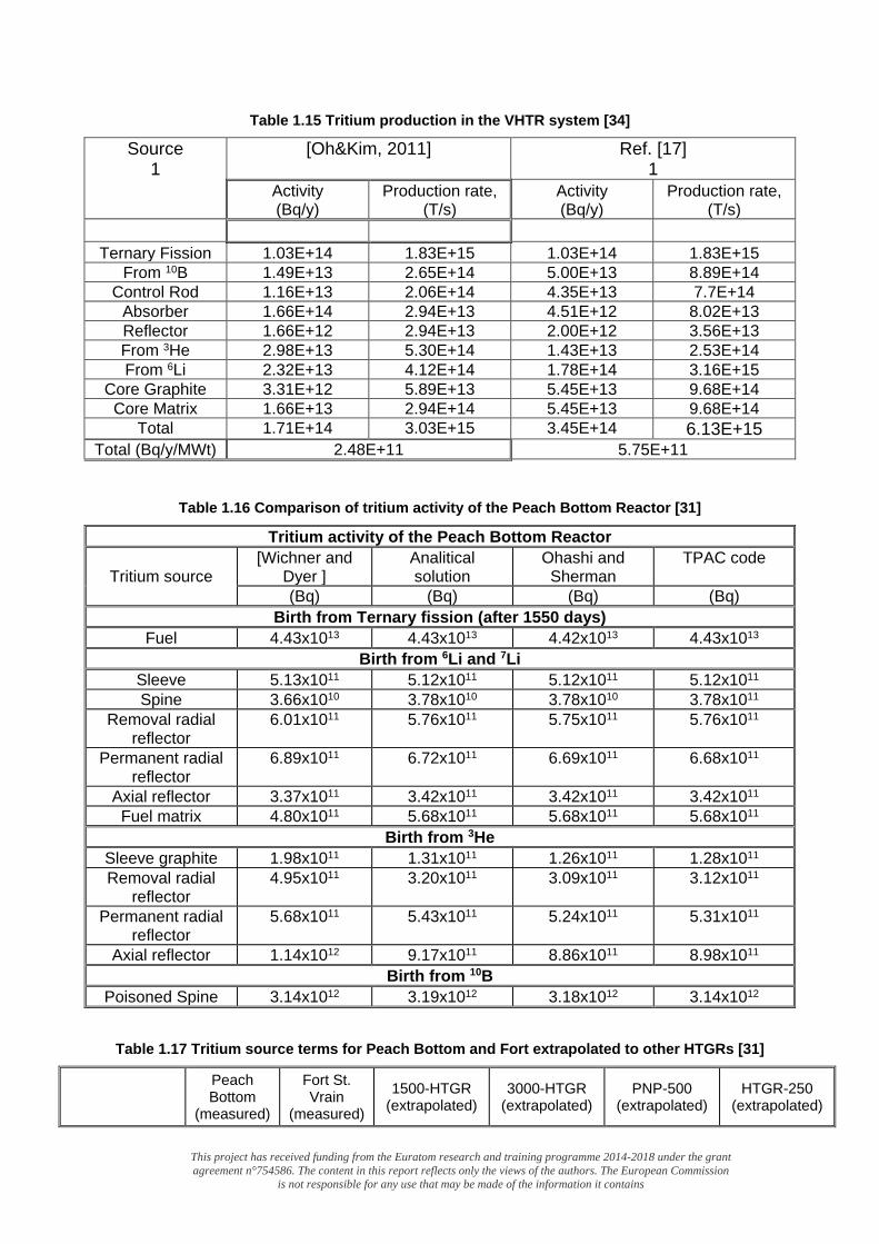
This project has received funding from the Euratom research and training programme 2014-2018 under the grant agreement n°754586. The content in this report reflects only the views of the authors. The European Commission
is not responsible for any use that may be made of the information it contains
Table 1.15 Tritium production in the VHTR system [34]
Source 1
[Oh&Kim, 2011]
Ref. [17] 1
Activity (Bq/y)
Production rate, (T/s)
Activity (Bq/y)
Production rate, (T/s)
Ternary Fission 1.03E+14 1.83E+15 1.03E+14 1.83E+15
From 10B 1.49E+13 2.65E+14 5.00E+13 8.89E+14 Control Rod 1.16E+13 2.06E+14 4.35E+13 7.7E+14
Absorber 1.66E+14 2.94E+13 4.51E+12 8.02E+13 Reflector 1.66E+12 2.94E+13 2.00E+12 3.56E+13 From 3He 2.98E+13 5.30E+14 1.43E+13 2.53E+14 From 6Li 2.32E+13 4.12E+14 1.78E+14 3.16E+15
Core Graphite 3.31E+12 5.89E+13 5.45E+13 9.68E+14 Core Matrix 1.66E+13 2.94E+14 5.45E+13 9.68E+14
Total 1.71E+14 3.03E+15 3.45E+14 6.13E+15 Total (Bq/y/MWt) 2.48E+11 5.75E+11
Table 1.16 Comparison of tritium activity of the Peach Bottom Reactor [31]
Tritium activity of the Peach Bottom Reactor
Tritium source [Wichner and
Dyer ] Analitical solution
Ohashi and Sherman
TPAC code
(Bq) (Bq) (Bq) (Bq) Birth from Ternary fission (after 1550 days)
Fuel 4.43x10¹³ 4.43x10¹³ 4.42x10¹³ 4.43x10¹³ Birth from 6Li and 7Li
Sleeve 5.13x10¹¹ 5.12x10¹¹ 5.12x10¹¹ 5.12x10¹¹ Spine 3.66x10¹⁰ 3.78x10¹⁰ 3.78x10¹⁰ 3.78x10¹¹
Removal radial reflector
6.01x10¹¹ 5.76x10¹¹ 5.75x10¹¹ 5.76x10¹¹
Permanent radial reflector
6.89x10¹¹ 6.72x10¹¹ 6.69x10¹¹ 6.68x10¹¹
Axial reflector 3.37x10¹¹ 3.42x10¹¹ 3.42x10¹¹ 3.42x10¹¹ Fuel matrix 4.80x10¹¹ 5.68x10¹¹ 5.68x10¹¹ 5.68x10¹¹
Birth from 3He Sleeve graphite 1.98x10¹¹ 1.31x10¹¹ 1.26x10¹¹ 1.28x10¹¹ Removal radial
reflector 4.95x10¹¹ 3.20x10¹¹ 3.09x10¹¹ 3.12x10¹¹
Permanent radial reflector
5.68x10¹¹ 5.43x10¹¹ 5.24x10¹¹ 5.31x10¹¹
Axial reflector 1.14x10¹² 9.17x10¹¹ 8.86x10¹¹ 8.98x10¹¹ Birth from 10B
Poisoned Spine 3.14x10¹² 3.19x10¹² 3.18x10¹² 3.14x10¹²
Table 1.17 Tritium source terms for Peach Bottom and Fort extrapolated to other HTGRs [31]
Peach Bottom
(measured)
Fort St. Vrain
(measured)
1500-HTGR (extrapolated)
3000-HTGR (extrapolated)
PNP-500 (extrapolated)
HTGR-250 (extrapolated)
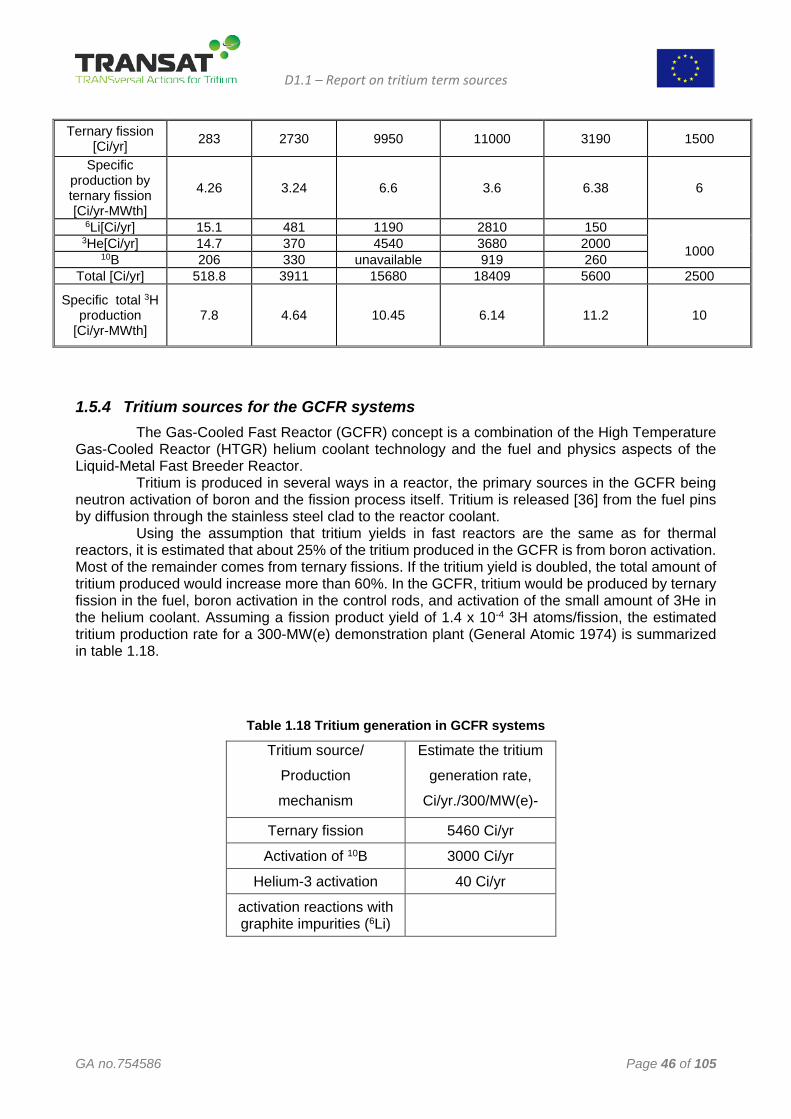
D1.1 – Report on tritium term sources
GA no.754586 Page 46 of 105
Ternary fission [Ci/yr] 283 2730 9950 11000 3190 1500
Specific production by ternary fission [Ci/yr-MWth]
4.26 3.24 6.6 3.6 6.38 6
6Li[Ci/yr] 15.1 481 1190 2810 150 1000
3He[Ci/yr] 14.7 370 4540 3680 2000 10B 206 330 unavailable 919 260
Total [Ci/yr] 518.8 3911 15680 18409 5600 2500
Specific total 3H production
[Ci/yr-MWth] 7.8 4.64 10.45 6.14 11.2 10
1.5.4 Tritium sources for the GCFR systems The Gas-Cooled Fast Reactor (GCFR) concept is a combination of the High Temperature Gas-Cooled Reactor (HTGR) helium coolant technology and the fuel and physics aspects of the Liquid-Metal Fast Breeder Reactor. Tritium is produced in several ways in a reactor, the primary sources in the GCFR being neutron activation of boron and the fission process itself. Tritium is released [36] from the fuel pins by diffusion through the stainless steel clad to the reactor coolant. Using the assumption that tritium yields in fast reactors are the same as for thermal reactors, it is estimated that about 25% of the tritium produced in the GCFR is from boron activation. Most of the remainder comes from ternary fissions. If the tritium yield is doubled, the total amount of tritium produced would increase more than 60%. In the GCFR, tritium would be produced by ternary fission in the fuel, boron activation in the control rods, and activation of the small amount of 3He in the helium coolant. Assuming a fission product yield of 1.4 x 10⁻⁴ 3H atoms/fission, the estimated tritium production rate for a 300-MW(e) demonstration plant (General Atomic 1974) is summarized in table 1.18.
Table 1.18 Tritium generation in GCFR systems
Tritium source/
Production
mechanism
Estimate the tritium
generation rate,
Ci/yr./300/MW(e)-
Ternary fission 5460 Ci/yr
Activation of 10B 3000 Ci/yr
Helium-3 activation 40 Ci/yr
activation reactions with graphite impurities (6Li)
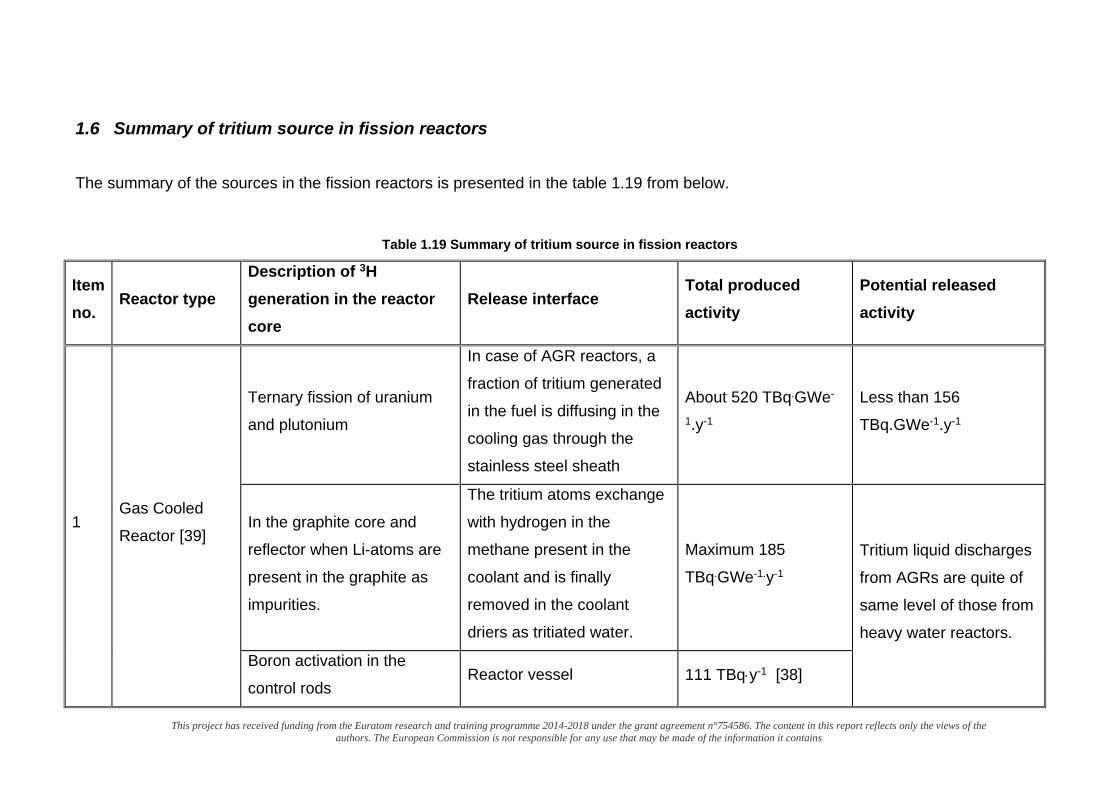
This project has received funding from the Euratom research and training programme 2014-2018 under the grant agreement n°754586. The content in this report reflects only the views of the authors. The European Commission is not responsible for any use that may be made of the information it contains
1.6 Summary of tritium source in fission reactors
The summary of the sources in the fission reactors is presented in the table 1.19 from below.
Table 1.19 Summary of tritium source in fission reactors
Item no.
Reactor type Description of 3H generation in the reactor core
Release interface Total produced activity
Potential released activity
1 Gas Cooled
Reactor [39]
Ternary fission of uranium
and plutonium
In case of AGR reactors, a
fraction of tritium generated
in the fuel is diffusing in the
cooling gas through the
stainless steel sheath
About 520 TBq.GWe-
1.y-1
Less than 156
TBq.GWe-1.y-1
In the graphite core and
reflector when Li-atoms are
present in the graphite as
impurities.
The tritium atoms exchange
with hydrogen in the
methane present in the
coolant and is finally
removed in the coolant
driers as tritiated water.
Maximum 185
TBq.GWe-1.y-1 Tritium liquid discharges
from AGRs are quite of
same level of those from
heavy water reactors.
Boron activation in the
control rods Reactor vessel 111 TBq⋅y-1 [38]
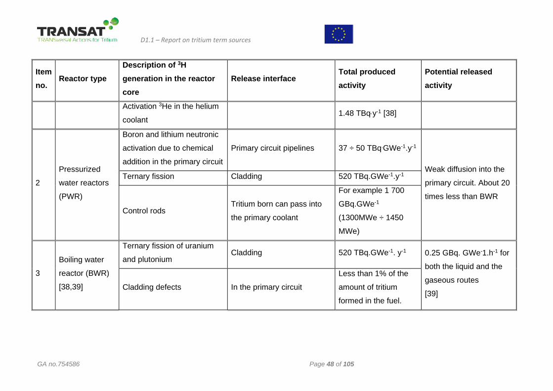
D1.1 – Report on tritium term sources
GA no.754586 Page 48 of 105
Item no.
Reactor type Description of 3H generation in the reactor core
Release interface Total produced activity
Potential released activity
Activation 3He in the helium
coolant 1.48 TBq⋅y-1 [38]
2
Pressurized
water reactors
(PWR)
Boron and lithium neutronic
activation due to chemical
addition in the primary circuit
Primary circuit pipelines 37 ÷ 50 TBq.GWe-1.y-1
Weak diffusion into the
primary circuit. About 20
times less than BWR
Ternary fission Cladding 520 TBq.GWe-1.y-1
Control rods Tritium born can pass into
the primary coolant
For example 1 700
GBq.GWe-1
(1300MWe ÷ 1450
MWe)
3
Boiling water
reactor (BWR)
[38,39]
Ternary fission of uranium
and plutonium Cladding 520 TBq.GWe-1. y-1 0.25 GBq. GWe-1.h-1 for
both the liquid and the
gaseous routes
[39] Cladding defects In the primary circuit
Less than 1% of the
amount of tritium
formed in the fuel.
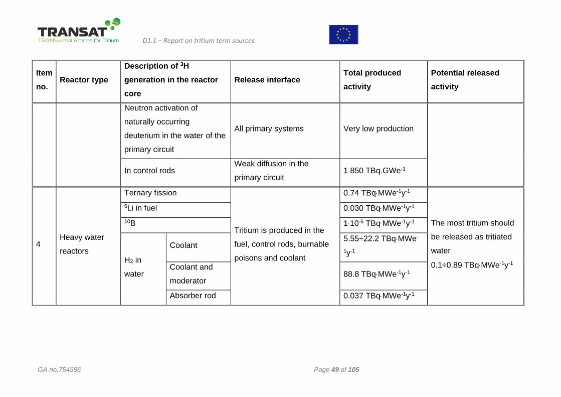
D1.1 – Report on tritium term sources
GA no.754586 Page 49 of 105
Item no.
Reactor type Description of 3H generation in the reactor core
Release interface Total produced activity
Potential released activity
Neutron activation of
naturally occurring
deuterium in the water of the
primary circuit
All primary systems Very low production
In control rods Weak diffusion in the
primary circuit 1 850 TBq.GWe-1
4 Heavy water
reactors
Ternary fission
Tritium is produced in the
fuel, control rods, burnable
poisons and coolant
0.74 TBq⋅MWe-1y-1
The most tritium should
be released as tritiated
water
0.1÷0.89 TBq⋅MWe-1y-1
6Li in fuel 0.030 TBq⋅MWe-1y-1 10B 1⋅10-6 TBq⋅MWe-1y-1
H2 in
water
Coolant 5.55÷22.2 TBq⋅MWe-
1y-1
Coolant and
moderator 88.8 TBq⋅MWe-1y-1
Absorber rod 0.037 TBq⋅MWe-1y-1
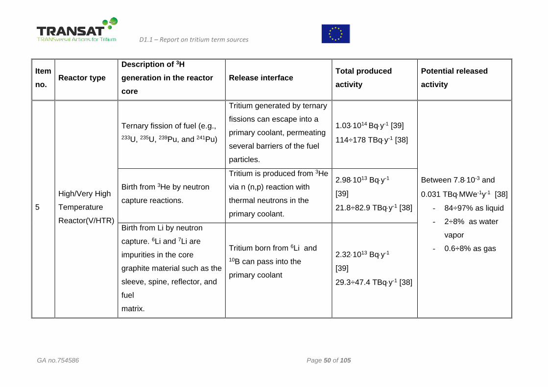
D1.1 – Report on tritium term sources
GA no.754586 Page 50 of 105
Item no.
Reactor type Description of 3H generation in the reactor core
Release interface Total produced activity
Potential released activity
5
High/Very High
Temperature
Reactor(V/HTR)
Ternary fission of fuel (e.g., 233U, 235U, 239Pu, and 241Pu)
Tritium generated by ternary
fissions can escape into a
primary coolant, permeating
several barriers of the fuel
particles.
1.03⋅1014 Bq⋅y-1 [39]
114÷178 TBq⋅y-1 [38]
Between 7.8⋅10-3 and
0.031 TBq⋅MWe-1y-1 [38]
- 84÷97% as liquid
- 2÷8% as water
vapor
- 0.6÷8% as gas
Birth from 3He by neutron
capture reactions.
Tritium is produced from 3He
via n (n,p) reaction with
thermal neutrons in the
primary coolant.
2.98⋅1013 Bq⋅y-1
[39]
21.8÷82.9 TBq⋅y-1 [38]
Birth from Li by neutron
capture. 6Li and 7Li are
impurities in the core
graphite material such as the
sleeve, spine, reflector, and
fuel
matrix.
Tritium born from 6Li and 10B can pass into the
primary coolant
2.32⋅1013 Bq⋅y-1
[39]
29.3÷47.4 TBq⋅y-1 [38]
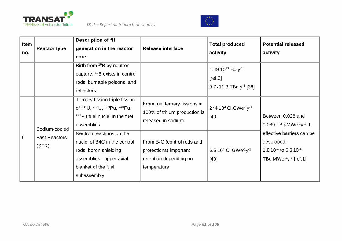
D1.1 – Report on tritium term sources
GA no.754586 Page 51 of 105
Item no.
Reactor type Description of 3H generation in the reactor core
Release interface Total produced activity
Potential released activity
Birth from 10B by neutron
capture. 10B exists in control
rods, burnable poisons, and
reflectors.
1.49⋅1013 Bq⋅y-1
[ref.2]
9.7÷11.3 TBq⋅y-1 [38]
6
Sodium-cooled
Fast Reactors
(SFR)
Ternary fission triple fission
of 235U, 238U, 239Pu, 240Pu, 241Pu fuel nuclei in the fuel
assemblies
From fuel ternary fissions ≈
100% of tritium production is
released in sodium.
2÷4⋅104 Ci.GWe-1y-1
[40] Between 0.026 and
0.089 TBq⋅MWe-1y-1. If
effective barriers can be
developed,
1.8.10-4 to 6.3.10-4
TBq⋅MWe-1y-1 [ref.1]
Neutron reactions on the
nuclei of B4C in the control
rods, boron shielding
assemblies, upper axial
blanket of the fuel
subassembly
From B4C (control rods and
protections) important
retention depending on
temperature
6.5⋅104 Ci⋅GWe-1y-1
[40]
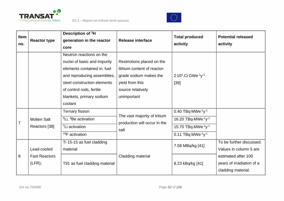
D1.1 – Report on tritium term sources
GA no.754586 Page 52 of 105
Item no.
Reactor type Description of 3H generation in the reactor core
Release interface Total produced activity
Potential released activity
Neutron reactions on the
nuclei of basic and impurity
elements contained in: fuel
and reproducing assemblies,
steel construction elements
of control rods, fertile
blankets, primary sodium
coolant
Restrictions placed on the
lithium content of reactor-
grade sodium makes the
yield from this
source relatively
unimportant
2.103.Ci⋅GWe-1y-1
[39]
7 Molten Salt
Reactors [38]
Ternary fission The vast majority of tritium
production will occur in the
salt
0.40 TBq⋅MWe-1y-1
6Li, 9Be activation 16.20 TBq⋅MWe-1y-1 7Li activation 15.70 TBq⋅MWe-1y-1 19F activation 0.11 TBq⋅MWe-1y-1
8
Lead-cooled
Fast Reactors
(LFR);
Ti 15-15 as fuel cladding
material
Cladding material
7.58 MBq/kg [41] To be further discussed.
Values in column 5 are
estimated after 100
years of irradiation of a
cladding material. T91 as fuel cladding material 8.23 kBq/kg [41]
This project has received funding from the Euratom research and training programme 2014-2018 under the grant agreement n°754586. The content in this report reflects only the views of the authors. The European Commission
is not responsible for any use that may be made of the information it contains
2 Tritium term sources in fusion reactors
Significant and promising developments have been achieved in the realization and operation of the fusion devices but fusion machine are still decades away from the commercial utilization. Different fusion plasma confinement concepts are under study, either based on magnetic fields to keep the plasma within the boundaries of a magnetic flask, or based on the inertia of plasma constituents. The status quo of nuclear fusion technology can be compared with the situation of nuclear fission about fifty to seventy years ago. At that time various concepts have been considered and tested to evaluate their best practicability and prospective to make nuclear fission power reactors economically and ecologically feasible as a primary energy source. Conversely, for nuclear fusion the final outcome of the competition between potential plasma confinement technologies is still completely open.
Experiments using Z-pinches for example virtually disappeared already from the research of fusion laboratories, mainly because of their tendency to produce neutron bursts originating from plasma instabilities. Similarly, further technological development of inertial confinement using deuterium / tritium targets ignited by LASERs is currently being discontinued. The follow-up project of NIF in the US called LIFE (LASER Inertial Fusion Energy) intended to increase the number of shots per unit of time compared to NIF and hence energy production by more than four orders of magnitude. However, LIFE was stopped in 2014.
As for magnetic confinement concept developments stellarators are much less advanced than tokamaks. Stellarators offer advantages in plasma stability and continues operation, but suffer from a quite complicated magnet design. One of the unresolved issues with tokamaks is plasma disruptions. Besides large devices like ITER and W7-X focus is nowadays also given to the development of smaller machines like spherical tokamaks or compact stellarators.
Apart from attempts to fuse 11B with 1H to 4He - a reaction which requires temperatures of about 3.5*109 degrees to overcome the Coulomb barriers - all fusion technology research is dedicated to the reaction between deuterium (2H or D) and tritium (3H or D) to 4He and a neutron at temperatures of around 1*108 degrees. Tritium is radioactive; the natural inventory on Earth is only about 2 to 4 kg. Tritium therefore need to be bred in fusion power plants from lithium. One of the concerns in fusion technology is tritium effluents and releases from future fusion power plants. Tritium can easily be measured down to very low concentrations, several orders of magnitude below today’s limits of the tritium contents in drinking water. Yet, tritium effluents and releases criteria are in the first place driven by its detectability.
The development of commercial fusion power production using deuterium (2H or D) and tritium (3H or T) is ongoing worldwide since decades. Large projects like ITER in France or NIF in the US are both publicly funded at investment levels of billions of € or $, respectively. The facility ITER - a large superconducting tokamak - is under design and construction at St. Paul Lez Durance in the South of France since 2006, with DT operation scheduled not before 2035 [42,43]. The European version of DEMO will undergo conceptual design between 2021 and 2027. However, the JET machine in Great Britain will again use tritium and DT in plasma operations already in the coming years [44].
Recently and in parallel to publicly funded projects efforts began to explore faster and cheaper ways to commercial fusion power production [45,46]. The different concepts are based on compact and flexible set-ups, allowing to modify the experiments in direct and quick responses to results. Also for some of these devices usage of deuterium and tritium are discussed.
Among the various ways to provide electrical power nuclear fusion will only be publicly accepted if the environmental impact is at tolerable levels. Auxiliary power requirements of fusion power plants will need to be optimized, and heat will need to be efficiently converted to electrical power through usage of high temperature steam. On the other hand, heat might need to be intermittently “stored” to account for pulsed plasma operation, on the expense of the temperature level available for steam generation. Tritium is highly mobile, and its containment and confinement becomes more difficult with increasing temperatures of structural materials; any effluents and releases shall be kept at an absolute minimum. Therefore tritium containment and confinement equipment and procedures need to be well integrated into the design and into operation of fusion power plants.
D1.1 – Report on tritium term sources
GA no.754586 Page 54 of 105
This chapter focusses on nuclear fusion and tritium usage in next step power reactors such as ITER and DEMO [47]. Tritium inventories and potential escape routes for tritium are identified and possible mitigation measures proposed where possible.
The regulations for working with tritium are plausibly dependent on the tritium amounts involved, significantly differ worldwide, and even differ in different European countries. In France for example tritium is formally considered a nuclear material, while Germany formally considers tritium a radioactive isotope.
None of the countries have developed specific laws or regulations and licensing conditions for nuclear fusion power reactors so far. However, attempts are being made to prepare for fusion technology specific Codes and Standards. An example is the transposition of ISO 17873 on ventilation systems in nuclear installations to make it applicable for fusion devices [48], or activities in ASME on fusion power construction materials [49].
The inventory of tritium, the processing throughput required, and the tritium consumption in fusion power plants is unprecedented. Almost 56 kg of tritium is consumed per GW- year (thermal) of fusion power; a 1 GWel reactor will therefore burn about 170 kg per year. Correspondingly, tritium breeding from lithium at a rate of almost 0.5 kg per day is required. As a result, the breeding and tritium processing systems will contain tritium at inventory levels of more than 10 kg, and will need to handle tritium throughputs of more than 1 kg per hour. Such amounts and throughputs may raise questions on tritium management and control, but are not addressed here and are outside of this deliverable. The tritium quantities in effluents and releases shall in any case be very low and intrinsically well below the accuracy limits of tritium tracking and accountancy, which can be anticipated for fusion power plants. This unquestionably does not mean that effluents and releases do not need to be measured in real time and quite accurately.
Working with tritium essentially involves two basic safety objectives [50]: 1. Confinement of tritium within its respective active and passive barriers; 2. Minimization of radiation dose to workers and the public. Accomplishing these safety objectives involves multiple measures and will be key to tritium usage
in fusion power plants.
2.1 The Nuclear Fuel Cycle of Fusion Power Reactors The burn-up fraction θ of deuterium and tritium fuelled into the plasma of nuclear fusion power
reactors is depending on plasma confinement technologies, is higher for inertial confinement in comparison to magnetic confinement, but in general is relatively low. ITER for example will have a θ < 10-2, i.e. less than 1%. Therefore, a large deuterium / tritium processing plant is needed [51], with throughputs unprecedented by about two orders of magnitude [52]. One of the central goals of the development of plasma physics is therefore to significantly increase θ, and at the same time to reduce the needs for processing of unburned fuel through a direct recycle of deuterium and tritium, at least partially and after removal of the fusion “ash” helium. Direct recycle requires minimizing production of impurities through plasma wall interactions, and for tokamaks limited application of techniques, which are introducing additional gases, e.g. deuterium for plasma stability control and disruption mitigation, or for radiative cooling of the divert or by argon or nitrogen injection.
A generic fuel cycle for nuclear fusion power reactors is outlined in figure 2.1. The plasma burning inside of a vacuum vessel is represented in D-shape as in magnetic plasma confinement machines. However, at the level shown the fuel cycle for inertial confinement machines would be very similar. The tritium breeding system of the fuel cycle is given in more detail in comparison to the Tritium Plant to allow for a more comprehensive discussion of the source terms of this part in the chapters below. Also, due to facilities like JET or TFTR and above all because of ITER, Tritium Plant processing systems have been already described in depth in different publications [53, 54].
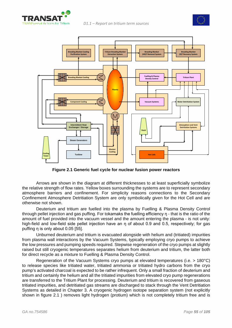
D1.1 – Report on tritium term sources
GA no.754586 Page 55 of 105
Plasma
Tritium Breeding BlanketExtraction System
Breeding Blanket(HD)T Removal System
Breeding Blanket(D)T Recovery System
Tritium PlantFuelling & PlasmaDensity Control
Vacuum Systems
Breeding Blanket CoolingPurification System
Breeding Blanket Cooling
Component Cooling
BlanketCooling
Steam Generators
Turbine
Atmosphere and Vent Detritiation Systems
Hot Cells
Intermittent Heat Exchanger / Storage
Water Detritiation System
Stack
CoolingTower
Figure 2.1 Generic fuel cycle for nuclear fusion power reactors
Arrows are shown in the diagram at different thicknesses to at least superficially symbolize
the relative strength of flow rates. Yellow boxes surrounding the systems are to represent secondary atmosphere barriers and confinement. For simplicity reasons connections to the Secondary Confinement Atmosphere Detritiation System are only symbolically given for the Hot Cell and are otherwise not shown.
Deuterium and tritium are fuelled into the plasma by Fuelling & Plasma Density Control through pellet injection and gas puffing. For tokamaks the fuelling efficiency η - that is the ratio of the amount of fuel provided into the vacuum vessel and the amount entering the plasma - is not unity: high-field and low-field side pellet injection have an η of about 0.9 and 0.5, respectively; for gas puffing η is only about 0.05 [55].
Unburned deuterium and tritium is evacuated alongside with helium and (tritiated) impurities from plasma wall interactions by the Vacuum Systems, typically employing cryo pumps to achieve the low pressures and pumping speeds required. Stepwise regeneration of the cryo pumps at slightly raised but still cryogenic temperatures separates helium from deuterium and tritium, the latter both for direct recycle as a mixture to Fuelling & Plasma Density Control.
Regeneration of the Vacuum Systems cryo pumps at elevated temperatures (i.e. > 180°C) to release species like tritiated water, tritiated ammonia or tritiated hydro carbons from the cryo pump’s activated charcoal is expected to be rather infrequent. Only a small fraction of deuterium and tritium and certainly the helium and all the tritiated impurities from elevated cryo pump regenerations are transferred to the Tritium Plant for processing. Deuterium and tritium is recovered from gaseous tritiated impurities, and detritiated gas streams are discharged to stack through the Vent Detritiation Systems as detailed in Chapter 3. A cryogenic hydrogen isotope separation system (not explicitly shown in figure 2.1 ) removes light hydrogen (protium) which is not completely tritium free and is
D1.1 – Report on tritium term sources
GA no.754586 Page 56 of 105
sent to the Water Detritiation System for decontamination, and isotope separation yields pure deuterium and tritium for plasma isotopic tailoring.
Another duty of the Tritium Plant is fuel storage, and controlled deuterium and tritium transfer to Fueling & Plasma Density Control to account for deficiencies from the partial direct recycle. The Tritium Plant also receives gases from the Breeding Blanket (D)T Recovery System, and a tritiated hydrogen gas mixture from the Water Detritiation System.
Atmospheres from secondary confinement and all gaseous discharges from tritium systems are treated in the Atmosphere and Vent Detritiation Systems. The tritiated water produced this way is processed in the Water Detritiation System based on Combined Electrolysis Catalytic Exchange (CECE). The products of CECE are all gaseous: a deuterium / tritium mixture which is transferred to the Tritium Plant, and light hydrogen (together with some deuterium) which is directly discharged to stack.
The tritium inventory Mi of the so-called inner fuel cycle of a nuclear fusion power reactor, i.e. the sum of the inventories of the Vacuum Systems, of Fuelling & Plasma Density Control, and of the Tritium Plant is strongly dependent on the tritium burn-up fraction θ, the tritium fuelling efficiency η, and the tritium processing time t. Even under partial direct recycle of deuterium and tritium, and with optimized burn-up fractions and tritium fuelling efficiencies Mi cannot be expected to be less than 10 kg [56].
The major duty of the Hot Cells shown in figure 2.1 is repair or refurbishment of components, tools, and equipment contaminated with tritium and / or activated by neutron exposure. Redundant components and modules have to be detritiated and conditioned in the Hot Cells prior to ultimate disposal as waste.
Vacuum vessel elements such as blanket modules or divertors are bulky, and due to e.g. tritium co-deposits and tritiated dusts their tritium content is significant; transport of these components to the Hot Cells requires remote operation and is challenging.
Tritium is continuously outgassing from the inner vacuum vessel components under exposure to air or nitrogen in the Hot Cells. The layout of the Hot Cell is therefore characterized by multiple confinement barriers, with interspace volumes served by detritiation systems. A vacuum oven (not explicitly shown in Figure 2.1) is to detritiate components prior to hand over to waste. Operation of the Hot Cell is also expected to produce liquid tritiated water, which is transferred to the Water Detritiation System.
Nuclear fusion power reactors need to breed their tritium from a lithium blanket surrounding the plasma in order to be self-sufficient in tritium fuel. The Tritium Breeding Ratio (TBR) is defined as the quotient of tritium atoms bred and tritium atoms burned. The TBR need to exceed unity by a margin to allow for bringing up all the tritium process inventories to the required operational levels, to compensate for radioactive decay (5.47% of the overall inventory per year), to provide a “reserve” storage inventory necessary for continued reactor operation under certain conditions, and to eventually supply tritium for start-up of other reactors [57].
The steady state inventory of the breeding blanket systems is reached once the production rate equals the breeding blanket tritium recovery (and the decay) rate and is dependent on the tritium residence time τ, i.e. the mean time a bred tritium atom remains in the breeding blanket systems until it is recovered and transferred to the Tritium Plant. One of the technological goals for tritium breeding blanket systems is therefore to make τ as low as possible. Nevertheless, with τ being of the order of 10 days [58] fusion power breeding blankets will contain at least 5 kg of tritium which need to be very well confined.
Quite a variety of breeding blanket concepts are under development worldwide using lithium in different chemical forms, e.g. as solids in ceramics like lithium silicates or lithium titanates, or as liquids in alloys like eutectic lithium-lead [59].
Tritium Breeding Blanket Extraction System are typically operated as loops and are often employing carrier gases. Details are depending on the breeding material and the blanket layout; protium is commonly added in large excess to extraction loops in order to enhance the efficiency of
D1.1 – Report on tritium term sources
GA no.754586 Page 57 of 105
tritium withdrawal through isotope exchange reactions [60]. As a result, the extracted tritium is in the chemical form of gaseous HT, often accompanied by tritiated water.
A Breeding Blanket (HD)T Removal System is needed to separate tritiated species from the extraction loops, and to convert tritiated water to molecular HT. The latter is transferred to the Breeding Blanket (D)T Recovery System, which in essence is a large hydrogen isotope separation facility. Recovered tritium is transferred to the Tritium Plant, and protium (and maybe deuterium) which can still contain residual tritium is returned to the Tritium Breeding Blanket Extraction System.
Various concepts are discussed for Breeding Blanket Cooling; the technologies are first of all and understandably linked to the breeding material of choice. Water, helium, eutectic alloys like lithium-lead or combinations of these media are under considerations. A common concern is tritium migration into Breeding Blanket Cooling. The cooling concepts therefore include a Breeding Blanket Cooling Purification System, at the end with transfer of molecular tritiated hydrogen to the Breeding Blanket (D)T Recovery System.
The thermal energy from the nuclear fusion reactions in the plasma is ultimately deposited in vacuum vessel blankets and components and is - together with the heat from exothermic transmutation reactions - employed to eventually drive the Steam Generators. Component Cooling and Blanket Cooling is separately shown in figure 2.1 just to represent various primary cooling loops. Depending on layout and operation different tritium concentration levels are to be expected in the primary cooling loops.
Permeation of tritium in the heat exchangers of the various primary cooling loops causes contamination of the secondary cooling loops. Considering tritium source terms an Intermittent Heat Exchanger / Storage is beneficial as it provides another tritium confinement barrier; however, it reduces the thermal to electrical energy conversation efficiency. A dry Cooling Tower is assumed to be employed for nuclear fusion power reactors in this deliverable to circumvent discharges of a potentially contaminated blow down, the latter therefore not considered here as a source term.
2.2 Identification of main Tritium Source Terms As a general rule, tritium can escape from systems due to limitations or insufficiencies in
confinement barriers. The assessable identification of tritium source terms in a nuclear fusion power reactor implies a comprehensive and complete functional analysis of the plant design and its layout. Tritium inventories in systems and the likelihood for any potential leakages vary with time. Thus, a broad number of operational and maintenance scenario trees need to be followed to recognize tritium source terms. Maintenance on tritium contaminated systems and components is known to often be a dominant cause for effluents and releases in comparison to operation and therefore requires particular attention.
Tritium can also escape as a consequence of operational deficiencies, of failure to follow procedures, of mistakes, and of incidents and accidents releasing inventories into confinement volumes or even into buildings and perhaps finally to the environment.
All in all, projections of tritium source terms of a fusion power plant requires at least a conceptual design comprising Process Flow Diagrams (PFDs) of primary systems and confinement systems together with pertinent arrangement drawings; in other words a coherent basis from which the source terms can be identified using functional trees and e.g. FMEA and / or HAZOP studies.
However, design and layout information available at present time on next step devices like DEMO for the development of fusion power plants beyond ITER is at best at pre-conceptual level. Nevertheless, tritium source terms need to be identified at very early stage to allow for mitigation of potential tritium effluents and releases through the development and application of advanced technologies, as well as through proper design of fusion power plants through all their phases.
In an attempt to pinpoint primary tritium source terms of future fusion power plants certain key systems, particularly those with a direct interface to the environment as reflected in figure 2.1, are
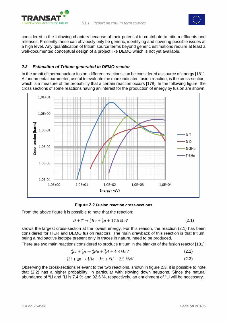
D1.1 – Report on tritium term sources
GA no.754586 Page 58 of 105
considered in the following chapters because of their potential to contribute to tritium effluents and releases. Presently these can obviously only be generic, identifying and covering possible issues at a high level. Any quantification of tritium source terms beyond generic estimations require at least a well-documented conceptual design of a project like DEMO which is not yet available.
2.3 Estimation of Tritium generated in DEMO reactor In the ambit of thermonuclear fusion, different reactions can be considered as source of energy [181]. A fundamental parameter, useful to evaluate the more indicated fusion reaction, is the cross-section, which is a measure of the probability that a certain reaction occurs [178]. In the following figure, the cross sections of some reactions having an interest for the production of energy by fusion are shown.
Figure 2.2 Fusion reaction cross-sections From the above figure it is possible to note that the reaction:
𝐷𝐷 + 𝑇𝑇 → 𝐻𝐻𝑒𝑒 + 𝑛𝑛 + 17.6 𝑀𝑀𝑒𝑒𝑀𝑀01
24 (2.1)
shows the largest cross-section at the lowest energy. For this reason, the reaction (2.1) has been considered for ITER and DEMO fusion reactors. The main drawback of this reaction is that tritium, being a radioactive isotope present only in traces in nature, need to be produced. There are two main reactions considered to produce tritium in the blanket of the fusion reactor [181]:
𝐿𝐿𝐿𝐿 + 𝑛𝑛01 →36 𝐻𝐻𝑒𝑒 + 𝐻𝐻 + 4.8 𝑀𝑀𝑒𝑒𝑀𝑀1
324 (2.2)
𝐿𝐿𝐿𝐿 + 𝑛𝑛01 →37 𝐻𝐻𝑒𝑒 + 𝑛𝑛01 + 𝐻𝐻 − 2.5 𝑀𝑀𝑒𝑒𝑀𝑀1
324 (2.3)
Observing the cross-sections relevant to the two reactions, shown in figure 2.3, it is possible to note that (2.2) has a higher probability, in particular with slowing down neutrons. Since the natural abundance of 6Li and 7Li is 7.4 % and 92.6 %, respectively, an enrichment of 6Li will be necessary.
1,0E-04
1,0E-03
1,0E-02
1,0E-01
1,0E+00
1,0E+01
1,0E+00 1,0E+01 1,0E+02 1,0E+03 1,0E+04
Cros
s-se
ctio
n (b
arns
)
Energy (keV)
D-T
D-D
D-3He
T-3He
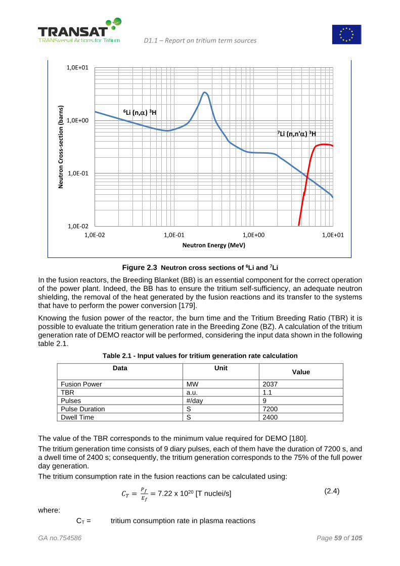
D1.1 – Report on tritium term sources
GA no.754586 Page 59 of 105
Figure 2.3 Neutron cross sections of 6Li and 7Li
In the fusion reactors, the Breeding Blanket (BB) is an essential component for the correct operation of the power plant. Indeed, the BB has to ensure the tritium self-sufficiency, an adequate neutron shielding, the removal of the heat generated by the fusion reactions and its transfer to the systems that have to perform the power conversion [179]. Knowing the fusion power of the reactor, the burn time and the Tritium Breeding Ratio (TBR) it is possible to evaluate the tritium generation rate in the Breeding Zone (BZ). A calculation of the tritium generation rate of DEMO reactor will be performed, considering the input data shown in the following table 2.1.
Table 2.1 - Input values for tritium generation rate calculation
Data
Unit Value
Fusion Power MW 2037 TBR a.u. 1.1 Pulses #/day 9 Pulse Duration S 7200 Dwell Time S 2400
The value of the TBR corresponds to the minimum value required for DEMO [180]. The tritium generation time consists of 9 diary pulses, each of them have the duration of 7200 s, and a dwell time of 2400 s; consequently, the tritium generation corresponds to the 75% of the full power day generation. The tritium consumption rate in the fusion reactions can be calculated using:
𝐶𝐶𝑇𝑇 = 𝑃𝑃𝑓𝑓
𝐸𝐸𝑓𝑓= 7.22 x 10²⁰ [T nuclei/s] (2.4)
where: CT = tritium consumption rate in plasma reactions
1,0E-02
1,0E-01
1,0E+00
1,0E+01
1,0E-02 1,0E-01 1,0E+00 1,0E+01
Neu
tron
Cro
ss-s
ectio
n (b
arns
)
Neutron Energy (MeV)
6Li (n,α) 3H
7Li (n,n'α) 3H
D1.1 – Report on tritium term sources
GA no.754586 Page 60 of 105
Pf = 2037 MW Ef = 17.6 MeV = 2.82 x 10⁻¹⁸ MJ
The tritium generation rate (fuel power day) in BZ results:
𝑆𝑆𝑇𝑇 = 𝐶𝐶𝑇𝑇 ∙ 𝑇𝑇𝐵𝐵𝑇𝑇 ∙ 𝐷𝐷 = 6.86 x 1025 [T nuclei/d] (2.5)
where: St = tritium generation rate (full power day) TBR = 1.1 D = 86400 s
Considering that the tritium generation corresponds to the 75% of the full power day generation, the generation rate of tritium per day corresponds to approx. 5.15 x 1025 tritium nuclei (257 g).
2.3.1 Atmosphere Detritiation Systems
As outlined above, all atmospheres actually or possibly containing tritium need to be detritiated in Atmosphere Detritiation Systems and eventually be decontaminated through the Vent Detritiation System prior to discharge to the environment.
Confinement Atmosphere Detritiation Systems usually operate in a recycle mode and as such do not provide a direct source term. The efficiency of tritium removal in a single pass is not too critical; the steady state tritium concentration in confinement volumes is governed by the volume exchange rate, adapted to the actual needs. However, excess gas need to be removed to maintain pressure gradients as required. Furthermore, the lower the tritium concentrations in an inner confinement volume the lower is the risk for airborne tritium in the next outer shell.
So-called Decontamination Factors (DFs) defined as the tritium concentration ratio at the inlet and the outlet of detritiation systems are often used to characterize the detritiation efficiency. However, it shall be noted that providing actual DFs is often confusing as higher inlet concentrations sometimes give rise to higher decontamination factors, and a tritium inlet concentration closed to zero under chronic contamination of the outlet even leads to DFs below unity. The outlet tritium concentrations at given discharge flow rates is therefore considered to be a much more appropriate notation.
Assuming a complete and quantitative oxidation of all tritiated species to water in the high temperature catalytic conversion step of detritiation systems the quality of decontamination is eventually determined by the removal efficiency of the tritiated water vapor from the atmospheres. A mathematical modelling comparison of different techniques like bubblers or adsorbers is given in [61]. A more recent development is the usage of wet scrubber columns in tritium confinement systems [53,54], meanwhile experimentally proven with tritium at semitechnical scale under different conditions [62]. One of the advantages of wet scrubber columns is the low risk for chronic tritium releases caused by contamination of the Vent Detritiation System outlet. The atmosphere outlet at the top of the column is the inlet for fresh water provided in a counter current mode; any transient elevated tritium contamination from e.g. operational off-sets is therefore quickly removed and the design conditions restored.
2.3.2 Water Detritiation
As shown in igure 2.1 the Water Detritiation System provides - besides the Vent Detritiation System - another exclusive and second discharge route for atmospheres to the stack. In order to manage and to control atmospheric tritium releases the limitation of atmospheric discharge routes to these two systems is absolutely essential.
Products of the Water Detritiation System have to be sufficiently decontaminated prior to discharge into the environment. Tritium discharges in liquid form (effluent water) are in general
D1.1 – Report on tritium term sources
GA no.754586 Page 61 of 105
considered to be more critical than atmospheric (gaseous) releases. Taking these matters into account the technology of choice for water detritiation is the Combined Electrolysis Catalytic Exchange (CECE) process [63].
The CECE process is based on electrolysis of water and catalyzed isotope exchange reactions and distillation employing fresh water in a column filled with a wet proof catalyst and packing material, and operated in counter current mode. This way the CECE process has two liquid feed streams, i.e. tritiated water and fresh water. Because all the water is electrolyzed the products are solely gaseous, i.e. an oxygen stream and a tritiated hydrogen stream. The oxygen stream is discharged through the Vent Detritiation System after removal of the tritiated water vapor in a condenser and dilution with air to exclude any explosion risks.
The tritiated hydrogen stream is sent to the cryogenic hydrogen isotope separation system of the Tritium Plant to take out the tritium. Because the isotope separation system cannot provide hydrogen with a sufficiently low tritium content it operates in direct conjunction with the Water Detritiation System and returns a hydrogen stream for decontamination [64]. A potential issue of the CECE process for water detritiation in a fusion power plant is the presence of deuterium. The latter is enriched in the counter current CECE column, and separation of deuterium and tritium is more difficult than separation of protium and tritium [65]. Particularly if deuterium is used in excess, e.g. because of deuterium neutral beam injection for heating purposes and / or deuterium massive pellet injection for disruption mitigation in tokamaks the cryogenic hydrogen isotope separation system could swamp the CECE column with deuterium, thereby increasing the risks for elevated tritium releases from the Water Detritiation System. 2.3.3 Cooling Loops
The cooling loops of a nuclear fusion power reactor have the potential to be accountable for one of the more severe source terms eventually causing tritium effluents and releases into the environment [66].
Primary cooling loops are necessarily operated at high temperatures, and the cooling media are separated from tritium holding parts of the fusion power plant by only a single physical barrier having large surface areas. Under these conditions, tritium is entering the primary cooling fluids through permeation; without extraction, a steady state tritium concentration is reached once the decay rate equals the permeation flow rates.
At this moment in time and until operational experiences become available any estimation of the tritium permeation fluxes into the primary cooling loops of fusion power plants can only be based on mock-up experimental data and on assumptions of their applicability. Sieverts’ law for example is often used in permeation calculations; however, external mass transfers can play an important role for given cases and thereby invalidating the use of this law [67]. The very low tritium partial pressures in the vacuum vessel for example are rather unlikely providing an appropriate measure to represent the chemical potential of tritium on the surface of first wall materials. The concentration of tritium ions in regions near to the first wall surface is above its thermal equilibrium due to the proximity to the fusion plasma, and radiochemical reactions need to be taken into account. Moreover, permeation barriers on the upstream side are expected to be unstable with time.
Primary cooling loops can reach notable tritium concentrations. Extraction of tritium from certain breeding blanket coolant media for example recover a significant fraction of the overall yield [68]. Water with elevated tritium concentrations is highly corrosive [69], undergoes self-radiolysis, and besides corrosion can be another primary cause for tritium permeation [70].
An important strategic element in multi-barrier confinement concepts is to allow for removal of tritium escaping from any part of the system as close as possible to the source; the removal technology should be such that tritium can easily be recovered. Continuous removal of tritium from primary fusion power plant cooling loops therefore appears to be an option, similar to the tritium removal from the heavy water moderator in CANDU fission reactors. For water coolants the closed circle technology for tritium stripping from CANDUs is directly applicable; tritium depleted cooling water can be returned into the primary loops.
D1.1 – Report on tritium term sources
GA no.754586 Page 62 of 105
Primary cooling loops of a fusion power plant are operated at much higher temperatures than in ITER; estimations on tritium concentrations in the water based primary heat transfer systems of ITER are thus not representative for fusion power plants; in comparison tritium permeation into the primary coolants of fusion power plants is much more pronounced.
Without continuous removal of tritium from primary cooling loops its steady state tritium concentrations can be expected to go above 10 TBqm-3, thereby forming a significant source term for tritium contamination of the secondary coolants.
The heat exchangers employed between the primary and secondary cooling loops provide a tritium barrier [71]. Assuming no intermittent fluids a single thin walled pipe or thin plate separates primary from secondary cooling loops. As shown in figure 2.1 there is no atmospheric confinement for secondary cooling loops and downstream systems. Any atmospheric release would therefore be an uncontrolled ground release; consequently, stringent requirements1 apply for tritium concentrations and the overall inventories of secondary cooling loops and all the downstream systems.
Tritium retention in the primary cooling loops and complying with very strict limitation of tritium concentrations in the secondary cooling loops is only achievable if heat exchanger construction metals are modified such that effective tritium permeation fluxes are minimized. Oxide layers on both upstream and downstream side potentially provide permeation reduction factors of orders of magnitude, but need to be stable under all operational conditions.
Detritiation of water from the secondary cooling loops does not appear to be an option. The CECE process requires tritium inlet concentrations > 100 MBqm-3. Water distillation for detritiation of water with lower tritium contents is economically questionable.
Eventually there is no difference in the principles and strategies for tritium confinement in cooling systems and for atmospheric tritium confinement. Active (detritiation) and passive (physical) barriers, following a “defense in depth” concept are the solutions for the challenges in cooling loops tritium confinement.
2.3.4 The Hot Cells
So far the Hot Cells are more or less neglected in the pre-conceptual design of nuclear fusion power reactors. However, the operation of Hot Cells is linked to handling of large tritium inventories, and is unavoidably contributing to effluents and releases from fusion power plants. Hot Cells effluents and releases can only be minimized through multiple leak tight “Russian doll” containments and extended closed loop atmospheric detritiation to well maintain tritium concentrations gradients within the confinement systems.
Transport of activated and contaminated components from the inside of the vacuum vessel to the Hot Cells involves crossing secondary containment barriers, requires complete remote handling, and is asking for high integrity confinement during transportation.
Only a limited data base is available on tritium outgassing from plasma facing components. As for apparent tritium permeability of membranes also estimations and extrapolations on outgassing rates of plasma facing components are dependent on assumptions and their validity. Tritium breeding blanket modules are to be replaced once they become depleted in lithium and hence losing their tritium breeding efficiency. Detritiation and / or refurbishing of these modules involves technologies which are in their very early stages of developments 2.3.5 Tritium Contaminated Solid Waste
Redundant solid components and materials are detritiated in the Hot Cells and then further conditioned as waste, e.g. by compaction and eventually packing in drums and containers for
1 Among others the requirements will eventually be derived using dose calculations on the “most exposed individual” and as such are site specific. No estimations can be given on absolute figures as there is no basis available yet.
D1.1 – Report on tritium term sources
GA no.754586 Page 63 of 105
ultimate disposal. However, the individual packages can still contain tens of grams of non-removable tritium. Solid waste need to be handled in any event such that it will not provide a releasable tritium source term, and is therefore not further considered here. 2.3.6 Maintenance
Even though the systematic of this chapter follows a systems by systems approach and does not explicitly consider activities maintenance on tritium bearing systems, particularly on those with high inventories, is potentially leading to elevated effluents and releases and is therefore at least briefly discussed here.
As an example maintenance on the vacuum vessel may possibly involve gas padding or venting with sub-atmospheric pressure control through the Vent Detritiation System. Tritiated dust accumulates in the vacuum vessel of nuclear fusion power reactors, and depending on first wall materials tritium co-deposits add to the vacuum vessel inventory up to kilogram levels.
Methods to remove tritium in co-deposits and in tritiated dusts need to be developed and applied prior to vacuum vessel maintenance. Glow discharge cleaning and baking for example reduces tritium outgassing. Closed loop atmosphere detritiation removes airborne tritium and thereby limits tritium effluents from the Vent Detritiation System; even the most advanced technology will have finite decontamination capabilities.
2.4 Tritium Confinement and Permeation Hydrogen is the element with the largest number of chemical compounds; no other chemical
element can react in such a diversity by either giving or taking an electron to make a chemical bond. Hydrogen can interact with most metals. Hydrogen atoms are characteristically occupying
interstitial places in metal lattices and thereby bringing about a considerable solubility, or can even form metal hydrides. Only low activation energies are required to move a hydrogen atom to the next nearest neighbour place in the host lattice, leading to comparatively fast diffusion of hydrogen in metals. These facts have two major consequences when it comes to tritium handling and processing:
• Materials in contact with tritium will become contaminated through isotopic exchange with regular hydrogen (protium) which is always present;
• With tritium solubility and diffusivity both being significant in certain metals and alloys (including those typically employed as structural materials) permeation of tritium through walls cannot at all times be completely avoided.
2.4.1 Atmospheric Tritium Confinement
Airborne tritium confinement has to always involve a multi-barrier concept, employing active and passive measures. The international standard ISO 17873 provides criteria for the design and operation of ventilation systems for nuclear installations other than nuclear reactors [72], however is written around aerosols. The methodology of the transposition to tritium already mentioned in Chapter 2 is based on schemes of types of ventilations given in Annex B of the ISO 17873, i.e. the C1 to C4*** categorization for airborne contamination levels. It consists of extracting functional requirements of devices given in ventilation schemes for the different categories and eventually provides proposals for new ventilation schemes to account for tritium as a gaseous species.
Detailing ventilation schemes for different ventilation categories is beyond the scope of this deliverable. However, a simplified atmospheric confinement scheme for tritium holding systems is outlined in figure 2.4.
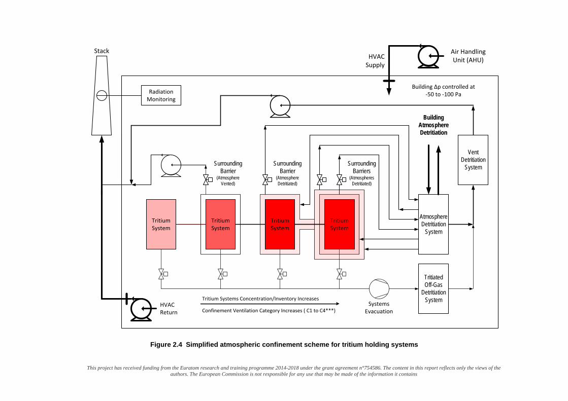
This project has received funding from the Euratom research and training programme 2014-2018 under the grant agreement n°754586. The content in this report reflects only the views of the authors. The European Commission is not responsible for any use that may be made of the information it contains
SurroundingBarrier
(AtmosphereDetritiated)
Stack
Tritium System
Tritium System
Tritium System
Tritium Systems Concentration/Inventory Increases
Radiation Monitoring
Tritium System
SurroundingBarrier
(AtmosphereVented)
Systems Evacuation
Air Handling Unit (AHU)HVAC
Supply
HVAC Return
Building Δp controlled at-50 to -100 Pa
BuildingAtmosphereDetritiation
Confinement Ventilation Category Increases ( C1 to C4***)
Atmosphere Detritiation
System
Vent Detritiation
SystemSurroundingBarriers
(AtmospheresDetritiated)
TritiatedOff-Gas
DetritiationSystem
Figure 2.4 Simplified atmospheric confinement scheme for tritium holding systems
This project has received funding from the Euratom research and training programme 2014-2018 under the grant agreement n°754586. The content in this report reflects only the views of the authors. The European Commission
is not responsible for any use that may be made of the information it contains
Tritium confinement follows a “Defense in Depth” concept. A requirement which cannot be compromised in tritium confinement is a building HVAC system capable of maintaining an overall sub-atmospheric pressure at a pressure difference Δp of – 50 to – 100 Pa. HVAC thereby provides an active confinement measure, with any credible tritium release controlled and not at ground level but at stack level. In case of elevated tritium concentrations in certain building volumes HVAC is isolated (as represented in figure 2.4) and the atmosphere detritiated in closed loop Atmosphere Detritiation Systems down to acceptable levels prior to putting HVAC on line again to minimize discharges to stack.
Radiation monitoring at the stack is used to accurately determine actual and chronic releases. It is based on real time radiation detection and accumulative measurements of tritium and tritiated compounds, along with measurements of the stack flow rate.
Tritium holding systems have to have a strong first passive (physical) barrier. Typically stainless steel is used as a construction material. The systems are designed and built with high leak tightness, employing a defined set of codes and standards, or at least employing good engineering practices.
It is self-evident that any gas evacuated from tritium systems must be detritiated prior to discharge to the environment. A dedicated Tritiated Off-Gas Detritiation System is needed upstream of the Vent Detritiation System, the latter operating in a “once through and out” mode.
With increasing systems tritium concentrations and systems tritium inventories the risks of elevated tritium levels within the next confinement enclosure may increase. Tritium escaping from inner systems with larger source terms therefore have to be additionally confined; the quality required for the actual confinement system is defined through the C1 to C4*** ventilation categorization.
Only systems with negligible inventories and / or low risks to cause airborne tritium contamination such as certain analytical devices (e.g. liquid scintillation counters) can be used without additional confinement. Reinforced ventilation can be acceptable in certain cases to protect workers, but obviously cannot protect the environment. Otherwise atmospheres in confinement volumes need to be detritiated in closed loops using Atmosphere Detritiation Systems as appropriate and defined through ventilation categorization. Pressure gradients are kept through discharges via the Vent Detritiation System.
Large volumes with substantial tritium concentrations such as Hot Cells handling in-vessel components having high tritium outgassing rates require a staged approach in barriers and in atmospheres detritiation.
Transfers of fluid tritium between systems are through double containment (typically coaxial) pipe work connections.
Transfers in general are often crossing outer containment barriers. For solids this requires atmosphere interlocks to avoid or at least to minimize cross contamination.
Atmosphere Detritiation Systems are typically based on oxidation of any tritium or tritiated compounds present in the atmosphere streams to tritiated water by heterogeneously catalyzed reactions on ceramic supported palladium at temperatures of up to 500°C. The tritiated water produced is then removed from the gaseous stream. For the latter purpose molecular sieves have been employed in the past, but meanwhile wet scrubbers have been developed and successfully tested [73]. The tritium concentration at the outlet of wet scrubber columns is inherently lower than at the outlet of molecular sieves, particularly when considering chronic releases. The efficiency of the tritiated water removal technology applied in the Vent Detritiation System eventually governs actual and chronical tritium releases by gaseous discharges.
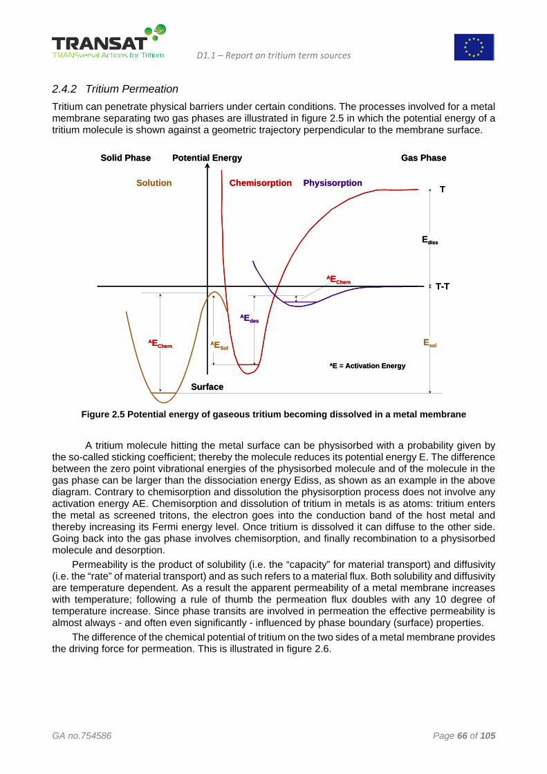
D1.1 – Report on tritium term sources
GA no.754586 Page 66 of 105
2.4.2 Tritium Permeation Tritium can penetrate physical barriers under certain conditions. The processes involved for a metal membrane separating two gas phases are illustrated in figure 2.5 in which the potential energy of a tritium molecule is shown against a geometric trajectory perpendicular to the membrane surface.
AE = Activation Energy
Surface
Solid Phase Gas Phase
Chemisorption Physisorption
T-T
T
Ediss
AEdes
AEChem
AEChem AESolEsol
Solution
Potential Energy
AE = Activation Energy
Surface
Solid Phase Gas Phase
Chemisorption Physisorption
T-T
T
Ediss
AEdes
AEChem
AEChem AESolEsol
Solution
Potential Energy
Figure 2.5 Potential energy of gaseous tritium becoming dissolved in a metal membrane
A tritium molecule hitting the metal surface can be physisorbed with a probability given by
the so-called sticking coefficient; thereby the molecule reduces its potential energy E. The difference between the zero point vibrational energies of the physisorbed molecule and of the molecule in the gas phase can be larger than the dissociation energy Ediss, as shown as an example in the above diagram. Contrary to chemisorption and dissolution the physisorption process does not involve any activation energy AE. Chemisorption and dissolution of tritium in metals is as atoms: tritium enters the metal as screened tritons, the electron goes into the conduction band of the host metal and thereby increasing its Fermi energy level. Once tritium is dissolved it can diffuse to the other side. Going back into the gas phase involves chemisorption, and finally recombination to a physisorbed molecule and desorption.
Permeability is the product of solubility (i.e. the “capacity” for material transport) and diffusivity (i.e. the “rate” of material transport) and as such refers to a material flux. Both solubility and diffusivity are temperature dependent. As a result the apparent permeability of a metal membrane increases with temperature; following a rule of thumb the permeation flux doubles with any 10 degree of temperature increase. Since phase transits are involved in permeation the effective permeability is almost always - and often even significantly - influenced by phase boundary (surface) properties.
The difference of the chemical potential of tritium on the two sides of a metal membrane provides the driving force for permeation. This is illustrated in figure 2.6.
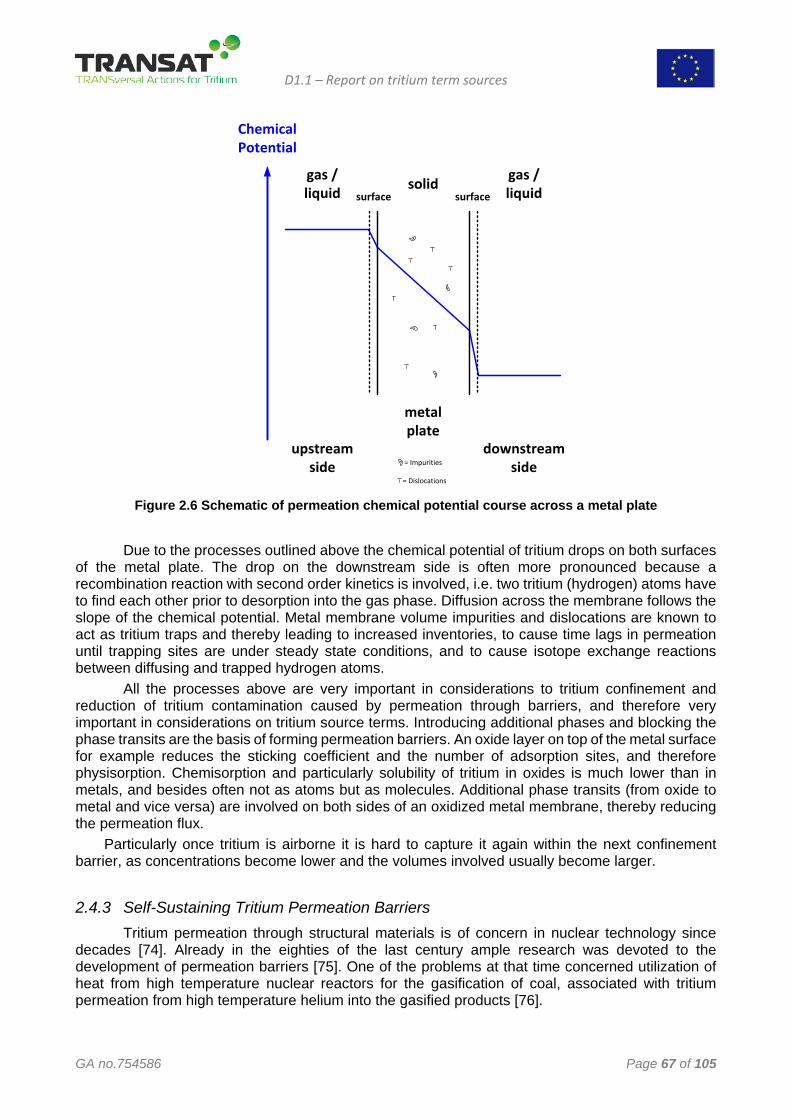
D1.1 – Report on tritium term sources
GA no.754586 Page 67 of 105
ChemicalPotential
upstreamside
gas /liquid solid gas /
liquidsurface surface
downstreamside
metalplate
= Impurities
= Dislocations Figure 2.6 Schematic of permeation chemical potential course across a metal plate
Due to the processes outlined above the chemical potential of tritium drops on both surfaces
of the metal plate. The drop on the downstream side is often more pronounced because a recombination reaction with second order kinetics is involved, i.e. two tritium (hydrogen) atoms have to find each other prior to desorption into the gas phase. Diffusion across the membrane follows the slope of the chemical potential. Metal membrane volume impurities and dislocations are known to act as tritium traps and thereby leading to increased inventories, to cause time lags in permeation until trapping sites are under steady state conditions, and to cause isotope exchange reactions between diffusing and trapped hydrogen atoms.
All the processes above are very important in considerations to tritium confinement and reduction of tritium contamination caused by permeation through barriers, and therefore very important in considerations on tritium source terms. Introducing additional phases and blocking the phase transits are the basis of forming permeation barriers. An oxide layer on top of the metal surface for example reduces the sticking coefficient and the number of adsorption sites, and therefore physisorption. Chemisorption and particularly solubility of tritium in oxides is much lower than in metals, and besides often not as atoms but as molecules. Additional phase transits (from oxide to metal and vice versa) are involved on both sides of an oxidized metal membrane, thereby reducing the permeation flux.
Particularly once tritium is airborne it is hard to capture it again within the next confinement barrier, as concentrations become lower and the volumes involved usually become larger.
2.4.3 Self-Sustaining Tritium Permeation Barriers Tritium permeation through structural materials is of concern in nuclear technology since
decades [74]. Already in the eighties of the last century ample research was devoted to the development of permeation barriers [75]. One of the problems at that time concerned utilization of heat from high temperature nuclear reactors for the gasification of coal, associated with tritium permeation from high temperature helium into the gasified products [76].
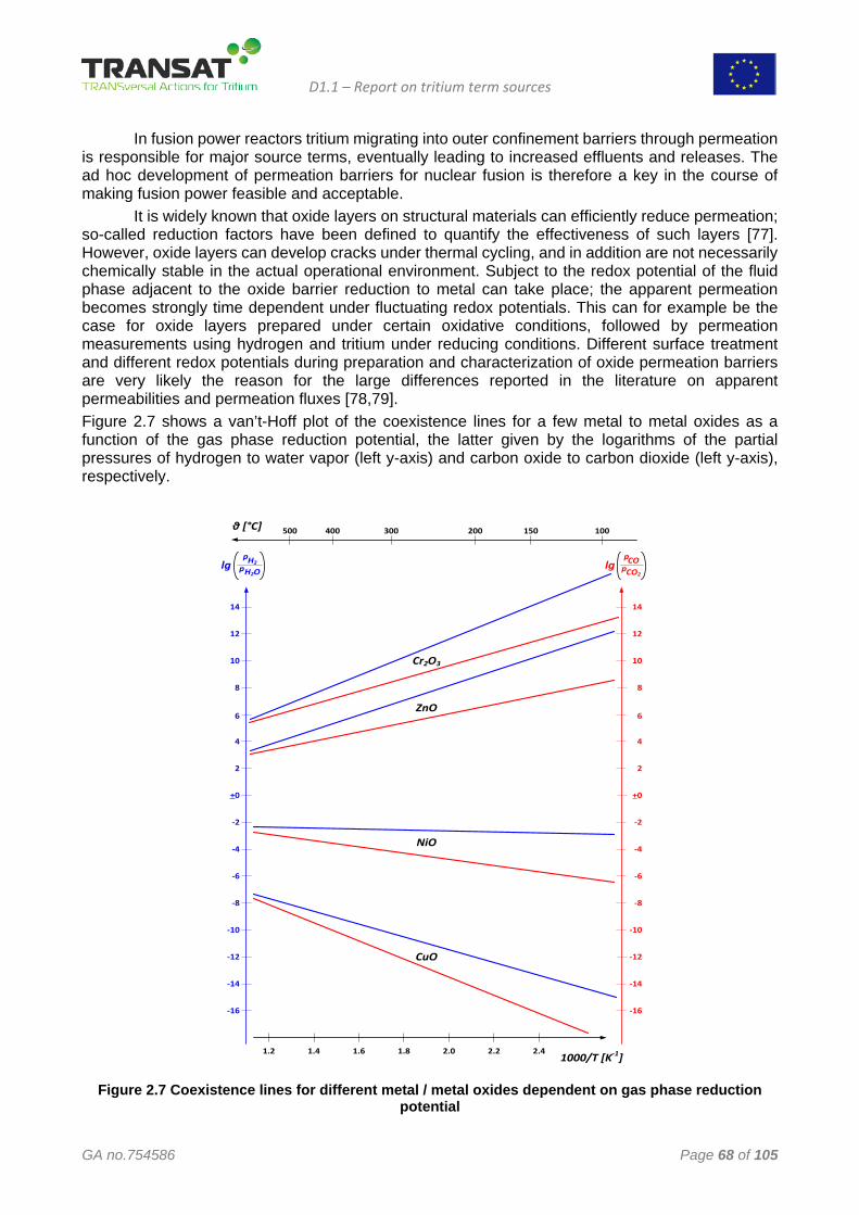
D1.1 – Report on tritium term sources
GA no.754586 Page 68 of 105
In fusion power reactors tritium migrating into outer confinement barriers through permeation is responsible for major source terms, eventually leading to increased effluents and releases. The ad hoc development of permeation barriers for nuclear fusion is therefore a key in the course of making fusion power feasible and acceptable.
It is widely known that oxide layers on structural materials can efficiently reduce permeation; so-called reduction factors have been defined to quantify the effectiveness of such layers [77]. However, oxide layers can develop cracks under thermal cycling, and in addition are not necessarily chemically stable in the actual operational environment. Subject to the redox potential of the fluid phase adjacent to the oxide barrier reduction to metal can take place; the apparent permeation becomes strongly time dependent under fluctuating redox potentials. This can for example be the case for oxide layers prepared under certain oxidative conditions, followed by permeation measurements using hydrogen and tritium under reducing conditions. Different surface treatment and different redox potentials during preparation and characterization of oxide permeation barriers are very likely the reason for the large differences reported in the literature on apparent permeabilities and permeation fluxes [78,79]. Figure 2.7 shows a van’t-Hoff plot of the coexistence lines for a few metal to metal oxides as a function of the gas phase reduction potential, the latter given by the logarithms of the partial pressures of hydrogen to water vapor (left y-axis) and carbon oxide to carbon dioxide (left y-axis), respectively.
-16
-14
-12
-10
-8
-6
-4
-2
+0
2
4
6
8
10
12
14
COCO2
pplg
H2OH2
pplg
-16
-14
-12
-10
-8
-6
-4
-2
+0
2
4
6
8
10
12
14
1000/T [K-1]
θ [°C]
1.6 1.8 2.0 2.2 2.41.41.2
500 400 300 200 150 100
CuO
NiO
ZnO
Cr2O3
Figure 2.7 Coexistence lines for different metal / metal oxides dependent on gas phase reduction
potential
D1.1 – Report on tritium term sources
GA no.754586 Page 69 of 105
Among the metals shown in the diagram copper is the easiest to reduce; on the other hand chromium requires considerable hydrogen to water vapor partial pressures to go from chromium oxide to the metal according to: Cr2O3 + 3 H2 → 2 Cr + 3 H2O.
Chromium is known to segregate to the surface of structural material alloys under oxidative conditions, particularly in alloys with low a carbon content; otherwise chromium concentrates on grain boundaries as chromium carbide.
It is explicitly noted that a chromium oxide layer is self-sustaining and even self-healing if cracks would occur from thermal cycling as long as the redox potential of the adjacent fluid phase has an oxidation potential above the one required to reverse the chemical reaction given above. Hence the elements used in oxide layer permeation barriers should be a constituent of the bulk alloy so that surface segregation supports self-sustaining and self-healing.
Structural materials and the redox potential on either side of confinement barrier should therefore be carefully selected in the design phase, and permeation barriers formed by oxidative pretreatment. An oxidative environment on the confinement barriers (on both upstream and downstream site if possible) should be maintained. Cold worked material should be annealed if possible to reduce dislocation densities and thereby tritium trapping in the bulk of materials. Permeation barriers should be operated at temperatures as low as possible and thermal cycling should be minimized.
Electro-polishing shall not at all be used for tritium bearing systems. It removes protective oxide layers and increases the surface near intrinsic hydrogen inventory, thereby leading to more pronounced tritium contamination through hydrogen isotope exchange.
3 Tritium anti-permeation barriers
3.1 Hydrogen isotopes permeation Permeability of hydrogen and its isotopes is generally defined as the steady state diffusional transport of atoms through a material that supports a differential pressure of the hydrogen isotope. assuming that the tritium partial pressure is negligible on one side of the plate of thickness t, the steady state diffusional flux can be expressed as:
𝐽𝐽 = 𝐷𝐷𝐷𝐷
𝜆𝜆 𝑝𝑝1/2 (3.1)
and the permeability:
𝛷𝛷 = 𝐷𝐷𝐾𝐾 (3.2)
The permeability is a materials property that characterizes diffusional transport through a bulk material, i.e., it is a relative measure of the transport of tritium when diffusion-limited transport dominates. [80] By definition, the permeability (as well as diffusivity and solubility) of hydrogen isotopes through metals is independent of surface condition, since it is related to diffusion of hydrogen through the material lattice (diffusivity) and the thermodynamic equilibrium between the gas and the metal(solubility).
Diffusivity, D, is a thermodynamic parameter, therefore, it follows the conventional Arrhenius-type dependence on temperature:
𝐷𝐷 = 𝐷𝐷0𝑒𝑒𝑒𝑒𝑝𝑝 �−𝐸𝐸𝐴𝐴𝑅𝑅𝑇𝑇� (3.3)
D1.1 – Report on tritium term sources
GA no.754586 Page 70 of 105
where D0 is a constant and EA is the activation energy of diffusion. Measuring tritium diffusion is non-trivial due to the availability of tritium. Therefore, hydrogen and deuterium are often used as surrogates. From classic rate theory, it is commonly inferred that the ratio of diffusivity of hydrogen isotopes is equivalent to the inverse ratio of the square root of the masses of the isotopes:
𝐷𝐷𝑇𝑇𝐷𝐷𝐻𝐻
= �𝑚𝑚𝐻𝐻𝑚𝑚𝑇𝑇
(3.4)
where m is the mass of the respective isotope, and the subscripts T and H refer to tritium and hydrogen respectively. When this approximation is invoked, the activation energy for diffusion is generally assumed to be independent of the mass of the isotope. Diffusion data at low temperatures do not support diffusion equation for a number of metals [81], however, at elevated temperatures, the inverse square root dependence on mass generally provides a reasonable approximation (especially for FCC structural metals) [82-88].
Solubility, K, represents equilibrium between the diatomic tritium molecule and tritium atoms in a structure matrix. The solubility, like diffusivity, generally follows the classic exponential dependence of thermodynamic parameters:
𝐾𝐾 = 𝐾𝐾0𝑒𝑒𝑒𝑒𝑝𝑝 �−∆𝐻𝐻𝑆𝑆𝑅𝑅𝑇𝑇� (3.5)
where o K is a constant and DHs is the standard enthalpy of dissolution of tritium (also called the heat of solution).
The chemical equilibrium between the diatomic gas and atomic tritium dissolved in a material lattice, assuming a dilute solution of dissolved tritium, can be expressed by Sievert’s Law:
𝐶𝐶0 = 𝐾𝐾(𝑝𝑝𝑇𝑇𝑇𝑇)1 2⁄ (3.6)
Where C0 is the equilibrium concentration and pTT is partial pressure of tritium.
Tritium can bond to microstructural features within metals, including vacancies, interfaces, grain boundaries and dislocations. This phenomenon is generally referred to as trapping. [89-98] The trapping of hydrogen and its isotopes is a thermally governed process with a characteristic energy generally referred to as the trap binding energy. This characteristic energy represents the reduction in the energy of the hydrogen relative to dissolution in the lattice [96,99] and can be thought of as the strength of the bond between the hydrogen isotope and the trap site to which it is bound. Traps sites affected the Diffusivity, in particular is possible to define an effective diffusivity proportional to D and a function of the relative amounts of trapped and lattice hydrogen:
𝐷𝐷𝑡𝑡𝑒𝑒𝑒𝑒 = 𝐷𝐷
1+𝑛𝑛𝑇𝑇𝑛𝑛𝐿𝐿𝑡𝑡𝑒𝑒𝑠𝑠�𝐸𝐸𝑡𝑡𝑅𝑅𝑇𝑇�
(3.6)
Where nt is the traps site, nL lattice site and Et trap binding energy. This means that materials with high solubilities of tritium (such as austenitic stainless steels), trapping may not affect transport significantly and Deff ≈ D. Instead, materials with low solubility and relatively large Et, the effective diffusivity can be substantially reduced compared to the lattice diffusivity. [100]
3.2 Structural materials
Structural materials for nuclear power conversion systems are simply those that comprise a majority of the plant. Most of them are expose to high neutron doses and used where the tritium is bred by
D1.1 – Report on tritium term sources
GA no.754586 Page 71 of 105
nuclear reactions. In this section are summarized the tritium permeation characteristic of the most used structural materials.
3.2.1 Austenitic stainless steels Austenitic stainless steels have been used extensively as a construction material for nuclear reactors, particularly type 316 austenitic stainless steel. The type 300-series austenitic stainless steels (Fe-Cr-Ni) have relatively high nickel content (commonly 8-14 wt.%), which is a detriment for fusion applications for several reasons including the susceptibility of nickel to activation induced radioactivity) [101-103]. The solubility and diffusivity of hydrogen and its isotopes through austenitic stainless steels has been extensively studied, this brief review focuses on the results for type 300-series alloys from gas permeation experiments. [104,105] The characteristics of hydrogen transport in austenitic stainless steels is independent of deformation when the deformation does not induce martensitic transformations [106-110]. The transport properties are also relatively insensitive to composition for the type 300-series alloys [105]. The most common type 300-series austenitic stainless steels are metastable, meaning that deformation can induce the formation of martensite in the austenitic matrix. This is important because strain-induced martensite has been shown to have a much higher diffusivity for hydrogen and its isotopes than austenite [111, 112]. This has implications on the apparent solubility as well. The stability of austenitic stainless steels with respect to the formation of strain-induced martensite increases most notably with nickel and nitrogen content (although other alloys also participate [112]). Therefore, effects of strain-induced martensite are most apparent on the low nickel type 300-series alloys, such as type 301 and 304, although type 316 austenitic stainless steel can transform (e.g., if nickel content is relatively low or if deformed at low temperature).
The Fe-Cr-Mn austenitic stainless steels have been considered as substitute for the more common grades of austenitic stainless steels since they have only nominal nickel content, although low-activation ferritic/martensitic steels have received more attention (see subsequent section). Alloys that have been considered typically contain both Cr and Mn in the range 10-20 wt.%, often with small amounts of other alloying elements. Unlike the Fe-Cr-Ni austenitic stainless steels, there are few reports of transport properties for the Fe-Cr-Mn austenitic alloys. [113]
The solubility of hydrogen and its isotopes in the Fe-Cr-Ni austenitic stainless steels is high relative to most structural materials. Compilation of data from gas permeation studies shows that most studies are consistent with one another, while studies that considered a variety of alloys within this class show that the solubility of hydrogen is essentially the same for a wide range of type 300-series austenitic stainless [107, 108, 110]. The heat of solution of hydrogen is austenitic stainless steels is relatively low (ΔHs = 6.9 kJ mol-1), thus the equilibrium content of hydrogen in the metal remains high even at room temperature. Table 1 lists the recommended transport properties for austenitic stainless steels (and a number of other metals and alloys). While the solubility appears to be insensitive to composition for the type 300-series alloys, the Fe-Cr-Ni-Mn alloys (which have not been widely considered for fusion applications) feature solubility that is more than 50% higher. [105]
Austenitic stainless steels show significantly lower permeability of hydrogen than other structural steels, particularly at low temperature. The low permeability can be attributed to the low diffusivity in these steels. The solubility of hydrogen and its isotopes, on the other hand, is large in austenitic stainless steels compared to other structural steels and the heat of dissolution is significantly lower than other metals. Thus, the tritium inventory in austenitic stainless steels can be relatively high even at low temperature. The low binding energy associated with trapping of hydrogen in austenitic stainless steel, combined with the high solubility, equates to essentially no contribution of trapping to the hydrogen inventory.
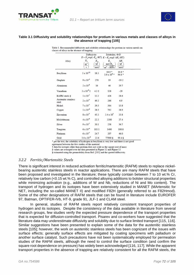
D1.1 – Report on tritium term sources
GA no.754586 Page 72 of 105
Table 3.1 Diffusivity and solubility relationships for protium in various metals and classes of alloys in
the absence of trapping [105]
3.2.2 Ferritic/Martensitic Steels There is significant interest in reduced activation ferritic/martensitic (RAFM) steels to replace nickel-bearing austenitic stainless steels in reactor applications. There are many RAFM steels that have been proposed and investigated in the literature; these typically contain between 7 to 10 wt.% Cr, relatively low carbon (<0.15 wt.% C), and controlled alloying additions to bolster structural properties while minimizing activation (e.g., additions of W and Nb, reductions of Ni and Mo content). The transport of hydrogen and its isotopes have been extensively studied in MANET (MArtensitic for NET, including the so-called MANET II) and modified F82H (generally referred to as F82Hmod). Some of the other designations of RAFM steels that can be found in literature include EUROFER 97, Batman, OPTIFER-IVb, HT-9, grade 91, JLF-1 and CLAM steel.
In general, studies of RAFM steels report relatively consistent transport properties of hydrogen and its isotopes. Despite the consistency of the data available in literature from several research groups, few studies verify the expected pressure dependence of the transport properties that is expected for diffusion-controlled transport. Pisarev and co-workers have suggested that the literature data may underestimate diffusivity and solubility due to surface limited transport [115, 116]. Similar suggestions have been presented to explain some of the data for the austenitic stainless steels [105]; however, the work on austenitic stainless steels has been cognizant of the issues with surface effects; generally surface effects are mitigated by coating specimens with palladium or another surface catalyst. Such precautions have not been systematically employed for permeation studies of the RAFM steels, although the need to control the surface condition (and confirm the square root dependence on pressure) has widely been acknowledged [116, 117]. While the apparent transport properties in the absence of trapping are relatively consistent for all the RAFM steels, the
D1.1 – Report on tritium term sources
GA no.754586 Page 73 of 105
issue of surface effects and the suggestions of Pisarev, et al. need further validation in the literature because the transport of tritium is less likely to be affected by surface conditions.
The diffusivity and solubility of hydrogen and isotopes are consistently similar for all the RAFM steels that have been tested. RAFM steels show relatively rapid diffusion and low solubility of hydrogen and its isotopes at ambient temperature. The diffusivity is six orders of magnitude greater than the austenitic stainless steels at 300 K, while the solubility is more than three orders of magnitude lower than the austenitic stainless steels. The diffusivity of hydrogen and its isotopes are not strongly sensitive to temperature compared to most other metals. On the other hand, the heat of solution (ΔHs) for the RAFM steels is quite large, thus the solubility of hydrogen approaches than of austenitic stainless steels at temperatures greater than 1000 K. Consequently, at elevated temperature (e.g., greater than 700 K), the permeability is less than an order of magnitude greater than the austenitic stainless steels and within a factor of five at temperature greater than 1000 K. Trapping is significant in the RAFM steels at temperature less than about 573 K, thus the apparent diffusivity is much lower than expected from tests that are performed at higher temperature.
3.2.3 Zirconium alloys Zirconium alloys are corrosion resistant in aqueous environments and have low neutron cross sections [118]. However, Zr readily forms embrittling hydride precipitates. Zirconium alloys oxidize and the surface ZrO2 may be an effective permeation barrier, preventing both hydrogen release and formation of detrimental hydrides. Andrieu, et al. [119] demonstrated that the rate of tritium release of zircaloy-4 (Zry4) decreased substantially upon oxide formation in tritiated water. Zirconium has multiple phases in some potential temperatures of interest: at 833 K, alpha, beta, and gamma Zr coexist in equilibrium. Most solubility and diffusivity studies have been conducted on the single-phase alpha-Zr; generally, at 773 K and below. Above this temperature, Zr alloys dissolve up to 50 at. % H and this solubility decreases rapidly with decreasing temperature, causing hydride precipitates within the alloys. The solubility has been found to vary slightly with alloying content. Yamanaka, et al. [120] note that the solubility in the beta phase decreases with alloying additions, while the solubility in the alpha phase increases with alloying additions. The solubility of H in ZrO2, regardless of crystal structure (10-4-10-5 mol H per mol oxide), is much smaller than the base metal and is even smaller than that in Al2O3. Alpha ZrO2 exhibits a solubility almost an order of magnitude smaller than beta ZrO2 [121]. Based on observations of tritium segregation to some precipitates [119, 122], many authors [121, 133, 134] argue that intermetallic precipitates in zircaloy could be paths for short-circuit diffusion due to large reported values for solubility and diffusivity in some of these phases. However, these quantities appear to be relatively large for the Zr-matrix material. Further, autoradiography shows depletion in some Fe-rich precipitates and at 623 K, the diffusivity in ZrFe2 is 2.5x10⁻¹¹ m2s-1, slower than bare Zr [135]. The permeability values through hydrides might be larger due to the high solubility of hydrogen isotopes the hydride phase. However, the volume fraction of hydrides tends to be small and the activation energy has been shown to be independent of the presence of the hydride [136]. Zirconium alloys that lack an oxide layer are not useful in hydrogen environments that exceed the solubility of H in Zr, due to hydride formation. At relatively low use temperatures (<623 K), and in aqueous or otherwise oxidizing environments, zirconium oxide is able to grow and is an effective barrier against the permeation of hydrogen. Above this temperature, the integrity of the oxide layer cannot be maintained and the effective permeation of hydrogen isotopes is increased substantially.
3.3 Protective coating against tritium permeation Uncontrolled tritium transport in nuclear fusion power plants can lead tritium inventory build-up in plant, tritium-contaminated effluents, high tritium concentrations in work areas, hydrogen embrittlement of structural metals and more difficult tritium processing. Hydrogen isotopes barriers are necessary to kinetically limit the achievement of isotopic thermodynamic equilibrium through
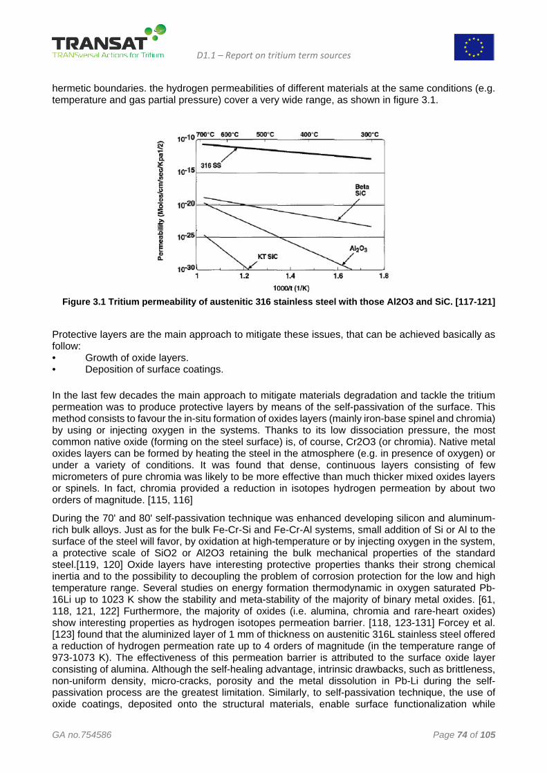
D1.1 – Report on tritium term sources
GA no.754586 Page 74 of 105
hermetic boundaries. the hydrogen permeabilities of different materials at the same conditions (e.g. temperature and gas partial pressure) cover a very wide range, as shown in figure 3.1.
Figure 3.1 Tritium permeability of austenitic 316 stainless steel with those Al2O3 and SiC. [117-121]
Protective layers are the main approach to mitigate these issues, that can be achieved basically as follow: • Growth of oxide layers. • Deposition of surface coatings. In the last few decades the main approach to mitigate materials degradation and tackle the tritium permeation was to produce protective layers by means of the self-passivation of the surface. This method consists to favour the in-situ formation of oxides layers (mainly iron-base spinel and chromia) by using or injecting oxygen in the systems. Thanks to its low dissociation pressure, the most common native oxide (forming on the steel surface) is, of course, Cr2O3 (or chromia). Native metal oxides layers can be formed by heating the steel in the atmosphere (e.g. in presence of oxygen) or under a variety of conditions. It was found that dense, continuous layers consisting of few micrometers of pure chromia was likely to be more effective than much thicker mixed oxides layers or spinels. In fact, chromia provided a reduction in isotopes hydrogen permeation by about two orders of magnitude. [115, 116]
During the 70' and 80' self-passivation technique was enhanced developing silicon and aluminum- rich bulk alloys. Just as for the bulk Fe-Cr-Si and Fe-Cr-Al systems, small addition of Si or Al to the surface of the steel will favor, by oxidation at high-temperature or by injecting oxygen in the system, a protective scale of SiO2 or Al2O3 retaining the bulk mechanical properties of the standard steel.[119, 120] Oxide layers have interesting protective properties thanks their strong chemical inertia and to the possibility to decoupling the problem of corrosion protection for the low and high temperature range. Several studies on energy formation thermodynamic in oxygen saturated Pb-16Li up to 1023 K show the stability and meta-stability of the majority of binary metal oxides. [61, 118, 121, 122] Furthermore, the majority of oxides (i.e. alumina, chromia and rare-heart oxides) show interesting properties as hydrogen isotopes permeation barrier. [118, 123-131] Forcey et al. [123] found that the aluminized layer of 1 mm of thickness on austenitic 316L stainless steel offered a reduction of hydrogen permeation rate up to 4 orders of magnitude (in the temperature range of 973-1073 K). The effectiveness of this permeation barrier is attributed to the surface oxide layer consisting of alumina. Although the self-healing advantage, intrinsic drawbacks, such as brittleness, non-uniform density, micro-cracks, porosity and the metal dissolution in Pb-Li during the self-passivation process are the greatest limitation. Similarly, to self-passivation technique, the use of oxide coatings, deposited onto the structural materials, enable surface functionalization while
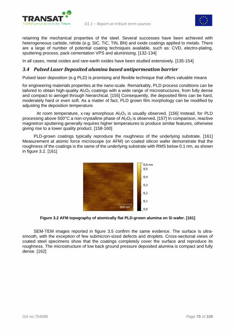
D1.1 – Report on tritium term sources
GA no.754586 Page 75 of 105
retaining the mechanical properties of the steel. Several successes have been achieved with heterogeneous carbide, nitride (e.g. SiC, TiC, TiN, BN) and oxide coatings applied to metals. There are a large of number of potential coating techniques available, such as: CVD, electro-plating, sputtering process, pack cementation VPS and aluminising. [132-134]
In all cases, metal oxides and rare-earth oxides have been studied extensively. [135-154]
3.4 Pulsed Laser Deposited alumina based antipermeation barrier Pulsed laser deposition (e.g PLD) is promising and flexible technique that offers valuable means
for engineering materials properties at the nano-scale. Remarkably, PLD process conditions can be tailored to obtain high-quality Al2O3 coatings with a wide range of microstructures, from fully dense and compact to aerogel through hierarchical. [155] Consequently, the deposited films can be hard, moderately hard or even soft. As a matter of fact, PLD grown film morphology can be modified by adjusting the deposition temperature.
At room temperature, x-ray amorphous Al2O3 is usually observed. [156] Instead, for PLD processing above 500°C a non-crystalline phase of Al2O3 is observed. [157] In comparison, reactive magnetron sputtering generally requires higher temperatures to produce similar features, otherwise giving rise to a lower quality product. [158-160]
PLD-grown coatings typically reproduce the roughness of the underlying substrate. [161] Measurement at atomic force microscope (or AFM) on coated silicon wafer demonstrate that the roughness of the coatings is the same of the underlying substrate with RMS below 0.1 nm, as shown in figure 3.2. [161]
Figure 3.2 AFM topography of atomically flat PLD-grown alumina on Si wafer. [161]
SEM-TEM images reported in figure 3.5 confirm the same evidence. The surface is ultra-
smooth, with the exception of few submicron-sized defects and droplets. Cross-sectional views of coated steel specimens show that the coatings completely cover the surface and reproduce its roughness. The microstructure of low back ground pressure deposited alumina is compact and fully dense. [162]
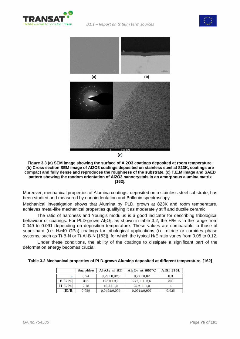
D1.1 – Report on tritium term sources
GA no.754586 Page 76 of 105
Figure 3.3 (a) SEM image showing the surface of Al2O3 coatings deposited at room temperature.
(b) Cross section SEM image of Al2O3 coatings deposited on stainless steel at 823K, coatings are compact and fully dense and reproduces the roughness of the substrate. (c) T.E.M image and SAED
pattern showing the random orientation of Al2O3 nanocrystals in an amorphous alumina matrix [162].
Moreover, mechanical properties of Alumina coatings, deposited onto stainless steel substrate, has been studied and measured by nanoindentation and Brillouin spectroscopy. Mechanical investigation shows that Alumina by PLD, grown at 823K and room temperature, achieves metal-like mechanical properties qualifying it as moderately stiff and ductile ceramic.
The ratio of hardness and Young's modulus is a good indicator for describing tribological behaviour of coatings. For PLD-grown Al2O3, as shown in table 3.2, the H/E is in the range from 0.049 to 0.091 depending on deposition temperature. These values are comparable to those of super-hard (i.e. H>40 GPa) coatings for tribological applications (i.e. nitride or carbides phase systems, such as Ti-B-N or Ti-Al-B-N [163]), for which the typical H/E ratio varies from 0.05 to 0.12.
Under these conditions, the ability of the coatings to dissipate a significant part of the deformation energy becomes crucial.
Table 3.2 Mechanical properties of PLD-grown Alumina deposited at different temperature. [162]
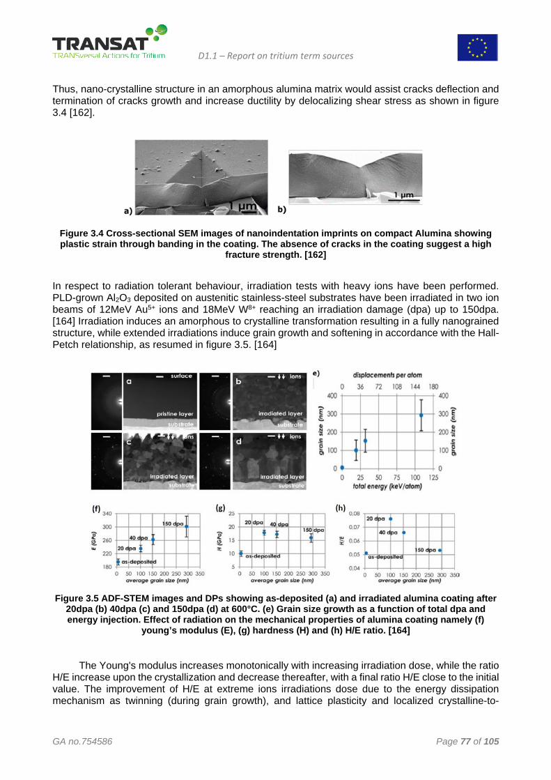
D1.1 – Report on tritium term sources
GA no.754586 Page 77 of 105
Thus, nano-crystalline structure in an amorphous alumina matrix would assist cracks deflection and termination of cracks growth and increase ductility by delocalizing shear stress as shown in figure 3.4 [162].
Figure 3.4 Cross-sectional SEM images of nanoindentation imprints on compact Alumina showing plastic strain through banding in the coating. The absence of cracks in the coating suggest a high
fracture strength. [162]
In respect to radiation tolerant behaviour, irradiation tests with heavy ions have been performed. PLD-grown Al2O3 deposited on austenitic stainless-steel substrates have been irradiated in two ion beams of 12MeV Au5+ ions and 18MeV W8+ reaching an irradiation damage (dpa) up to 150dpa. [164] Irradiation induces an amorphous to crystalline transformation resulting in a fully nanograined structure, while extended irradiations induce grain growth and softening in accordance with the Hall-Petch relationship, as resumed in figure 3.5. [164]
Figure 3.5 ADF-STEM images and DPs showing as-deposited (a) and irradiated alumina coating after
20dpa (b) 40dpa (c) and 150dpa (d) at 600°C. (e) Grain size growth as a function of total dpa and energy injection. Effect of radiation on the mechanical properties of alumina coating namely (f)
young’s modulus (E), (g) hardness (H) and (h) H/E ratio. [164]
The Young's modulus increases monotonically with increasing irradiation dose, while the ratio H/E increase upon the crystallization and decrease thereafter, with a final ratio H/E close to the initial value. The improvement of H/E at extreme ions irradiations dose due to the energy dissipation mechanism as twinning (during grain growth), and lattice plasticity and localized crystalline-to-
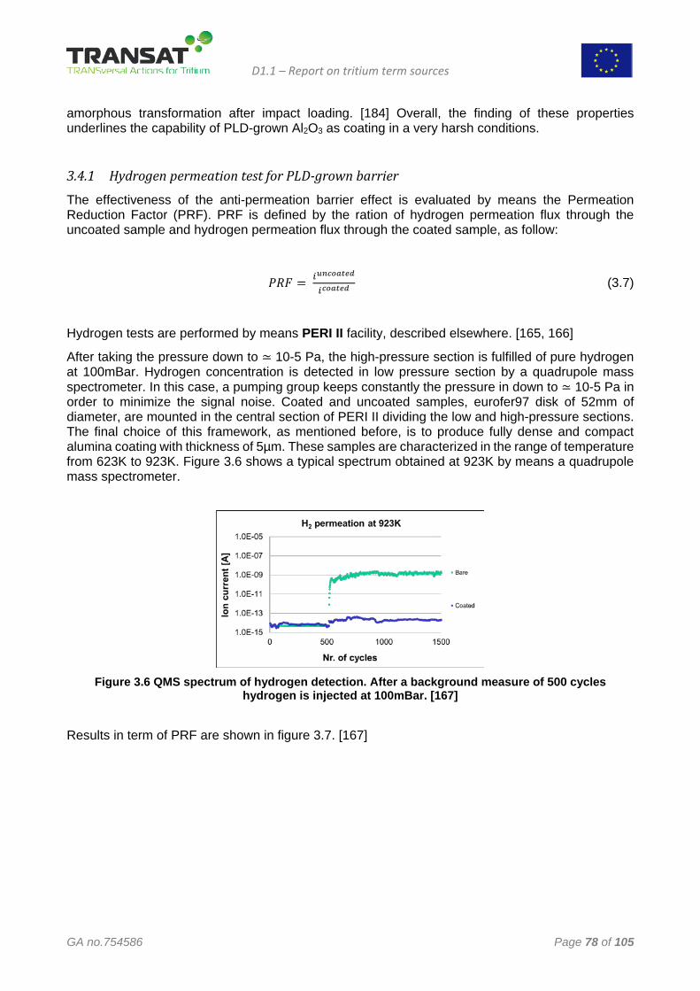
D1.1 – Report on tritium term sources
GA no.754586 Page 78 of 105
amorphous transformation after impact loading. [184] Overall, the finding of these properties underlines the capability of PLD-grown Al2O3 as coating in a very harsh conditions.
3.4.1 Hydrogen permeation test for PLD-grown barrier
The effectiveness of the anti-permeation barrier effect is evaluated by means the Permeation Reduction Factor (PRF). PRF is defined by the ration of hydrogen permeation flux through the uncoated sample and hydrogen permeation flux through the coated sample, as follow:
𝑃𝑃𝑇𝑇𝑃𝑃 = 𝐶𝐶𝑢𝑢𝑛𝑛𝑢𝑢𝑢𝑢𝑢𝑢𝑡𝑡𝑢𝑢𝑢𝑢
𝐶𝐶𝑢𝑢𝑢𝑢𝑢𝑢𝑡𝑡𝑢𝑢𝑢𝑢 (3.7)
Hydrogen tests are performed by means PERI II facility, described elsewhere. [165, 166]
After taking the pressure down to ≃ 10-5 Pa, the high-pressure section is fulfilled of pure hydrogen at 100mBar. Hydrogen concentration is detected in low pressure section by a quadrupole mass spectrometer. In this case, a pumping group keeps constantly the pressure in down to ≃ 10-5 Pa in order to minimize the signal noise. Coated and uncoated samples, eurofer97 disk of 52mm of diameter, are mounted in the central section of PERI II dividing the low and high-pressure sections. The final choice of this framework, as mentioned before, is to produce fully dense and compact alumina coating with thickness of 5µm. These samples are characterized in the range of temperature from 623K to 923K. Figure 3.6 shows a typical spectrum obtained at 923K by means a quadrupole mass spectrometer.
Figure 3.6 QMS spectrum of hydrogen detection. After a background measure of 500 cycles
hydrogen is injected at 100mBar. [167]
Results in term of PRF are shown in figure 3.7. [167]
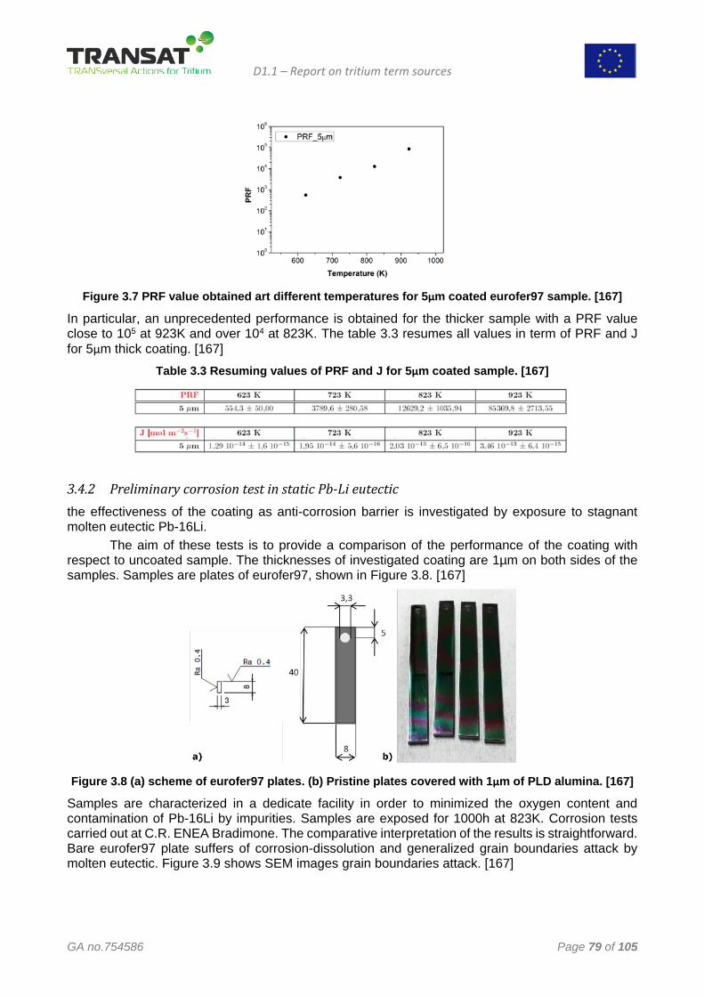
D1.1 – Report on tritium term sources
GA no.754586 Page 79 of 105
Figure 3.7 PRF value obtained art different temperatures for 5μm coated eurofer97 sample. [167]
In particular, an unprecedented performance is obtained for the thicker sample with a PRF value close to 105 at 923K and over 104 at 823K. The table 3.3 resumes all values in term of PRF and J for 5μm thick coating. [167]
Table 3.3 Resuming values of PRF and J for 5μm coated sample. [167]
3.4.2 Preliminary corrosion test in static Pb-Li eutectic the effectiveness of the coating as anti-corrosion barrier is investigated by exposure to stagnant molten eutectic Pb-16Li. The aim of these tests is to provide a comparison of the performance of the coating with respect to uncoated sample. The thicknesses of investigated coating are 1µm on both sides of the samples. Samples are plates of eurofer97, shown in Figure 3.8. [167]
Figure 3.8 (a) scheme of eurofer97 plates. (b) Pristine plates covered with 1μm of PLD alumina. [167]
Samples are characterized in a dedicate facility in order to minimized the oxygen content and contamination of Pb-16Li by impurities. Samples are exposed for 1000h at 823K. Corrosion tests carried out at C.R. ENEA Bradimone. The comparative interpretation of the results is straightforward. Bare eurofer97 plate suffers of corrosion-dissolution and generalized grain boundaries attack by molten eutectic. Figure 3.9 shows SEM images grain boundaries attack. [167]
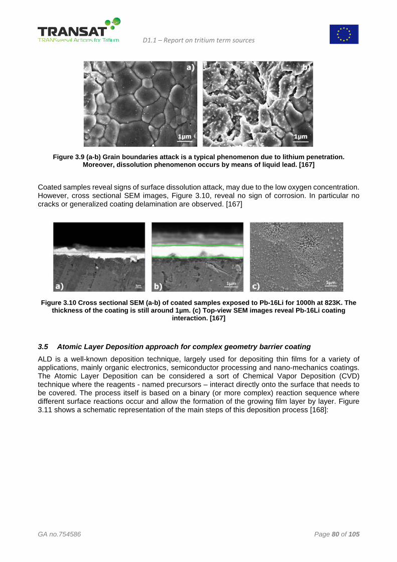
D1.1 – Report on tritium term sources
GA no.754586 Page 80 of 105
Figure 3.9 (a-b) Grain boundaries attack is a typical phenomenon due to lithium penetration.
Moreover, dissolution phenomenon occurs by means of liquid lead. [167]
Coated samples reveal signs of surface dissolution attack, may due to the low oxygen concentration. However, cross sectional SEM images, Figure 3.10, reveal no sign of corrosion. In particular no cracks or generalized coating delamination are observed. [167]
Figure 3.10 Cross sectional SEM (a-b) of coated samples exposed to Pb-16Li for 1000h at 823K. The
thickness of the coating is still around 1µm. (c) Top-view SEM images reveal Pb-16Li coating interaction. [167]
3.5 Atomic Layer Deposition approach for complex geometry barrier coating ALD is a well-known deposition technique, largely used for depositing thin films for a variety of applications, mainly organic electronics, semiconductor processing and nano-mechanics coatings. The Atomic Layer Deposition can be considered a sort of Chemical Vapor Deposition (CVD) technique where the reagents - named precursors – interact directly onto the surface that needs to be covered. The process itself is based on a binary (or more complex) reaction sequence where different surface reactions occur and allow the formation of the growing film layer by layer. Figure 3.11 shows a schematic representation of the main steps of this deposition process [168]:
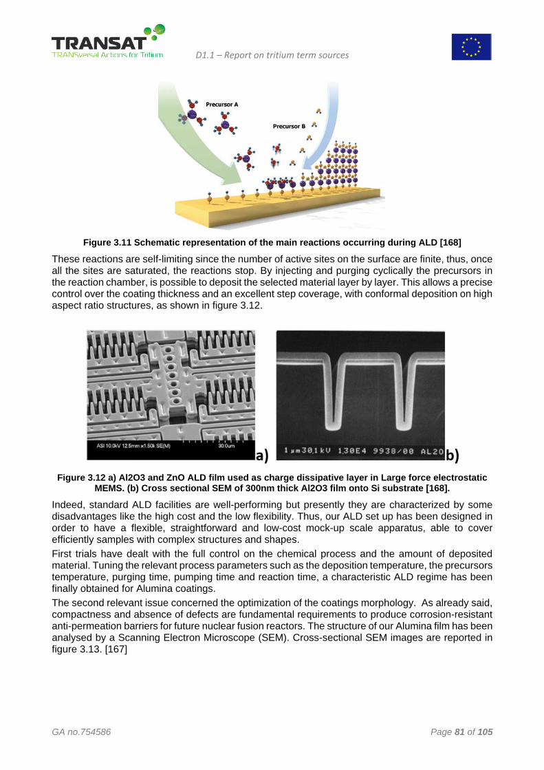
D1.1 – Report on tritium term sources
GA no.754586 Page 81 of 105
Figure 3.11 Schematic representation of the main reactions occurring during ALD [168]
These reactions are self-limiting since the number of active sites on the surface are finite, thus, once all the sites are saturated, the reactions stop. By injecting and purging cyclically the precursors in the reaction chamber, is possible to deposit the selected material layer by layer. This allows a precise control over the coating thickness and an excellent step coverage, with conformal deposition on high aspect ratio structures, as shown in figure 3.12.
Figure 3.12 a) Al2O3 and ZnO ALD film used as charge dissipative layer in Large force electrostatic
MEMS. (b) Cross sectional SEM of 300nm thick Al2O3 film onto Si substrate [168].
Indeed, standard ALD facilities are well-performing but presently they are characterized by some disadvantages like the high cost and the low flexibility. Thus, our ALD set up has been designed in order to have a flexible, straightforward and low-cost mock-up scale apparatus, able to cover efficiently samples with complex structures and shapes. First trials have dealt with the full control on the chemical process and the amount of deposited material. Tuning the relevant process parameters such as the deposition temperature, the precursors temperature, purging time, pumping time and reaction time, a characteristic ALD regime has been finally obtained for Alumina coatings. The second relevant issue concerned the optimization of the coatings morphology. As already said, compactness and absence of defects are fundamental requirements to produce corrosion-resistant anti-permeation barriers for future nuclear fusion reactors. The structure of our Alumina film has been analysed by a Scanning Electron Microscope (SEM). Cross-sectional SEM images are reported in figure 3.13. [167]
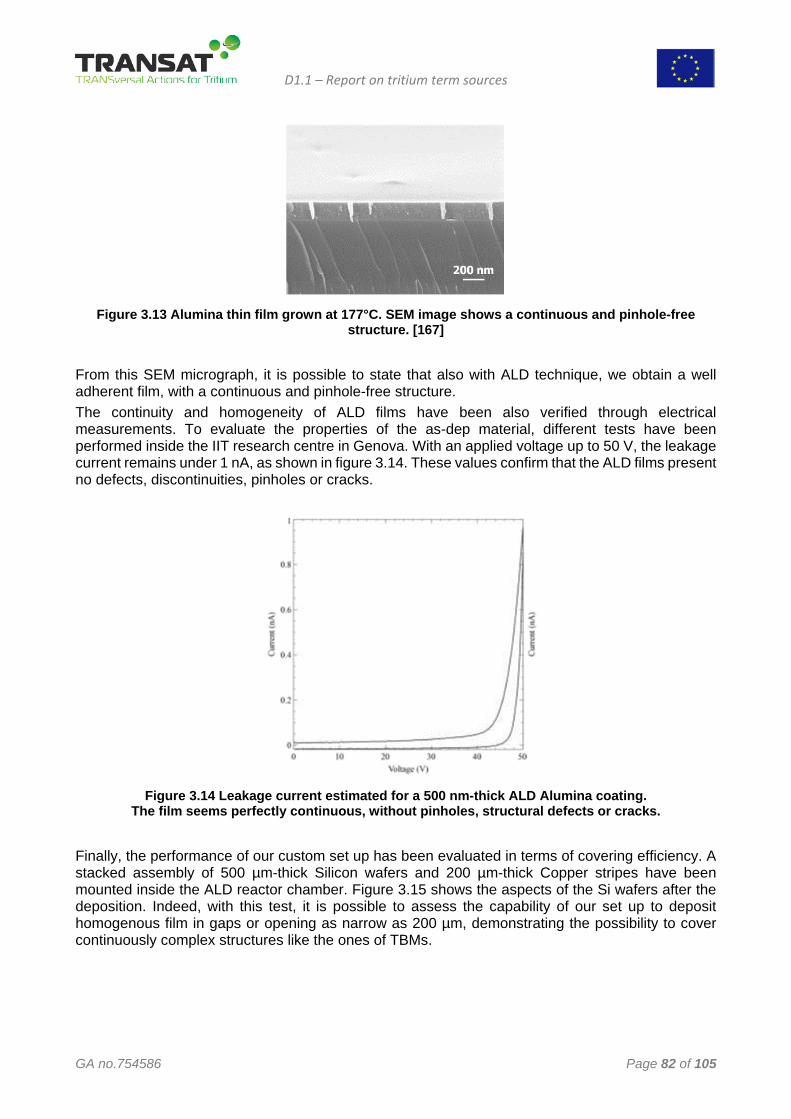
D1.1 – Report on tritium term sources
GA no.754586 Page 82 of 105
Figure 3.13 Alumina thin film grown at 177°C. SEM image shows a continuous and pinhole-free
structure. [167]
From this SEM micrograph, it is possible to state that also with ALD technique, we obtain a well adherent film, with a continuous and pinhole-free structure. The continuity and homogeneity of ALD films have been also verified through electrical measurements. To evaluate the properties of the as-dep material, different tests have been performed inside the IIT research centre in Genova. With an applied voltage up to 50 V, the leakage current remains under 1 nA, as shown in figure 3.14. These values confirm that the ALD films present no defects, discontinuities, pinholes or cracks.
Figure 3.14 Leakage current estimated for a 500 nm-thick ALD Alumina coating.
The film seems perfectly continuous, without pinholes, structural defects or cracks.
Finally, the performance of our custom set up has been evaluated in terms of covering efficiency. A stacked assembly of 500 µm-thick Silicon wafers and 200 µm-thick Copper stripes have been mounted inside the ALD reactor chamber. Figure 3.15 shows the aspects of the Si wafers after the deposition. Indeed, with this test, it is possible to assess the capability of our set up to deposit homogenous film in gaps or opening as narrow as 200 µm, demonstrating the possibility to cover continuously complex structures like the ones of TBMs.
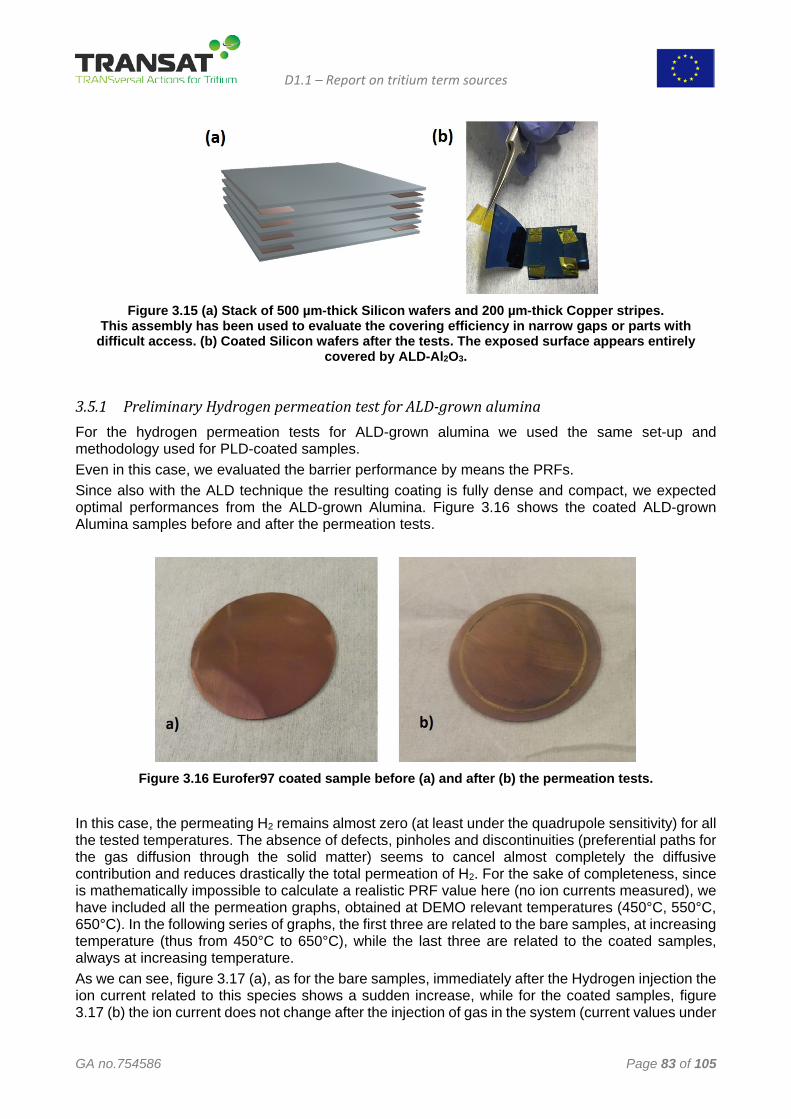
D1.1 – Report on tritium term sources
GA no.754586 Page 83 of 105
Figure 3.15 (a) Stack of 500 µm-thick Silicon wafers and 200 µm-thick Copper stripes.
This assembly has been used to evaluate the covering efficiency in narrow gaps or parts with difficult access. (b) Coated Silicon wafers after the tests. The exposed surface appears entirely
covered by ALD-Al2O3.
3.5.1 Preliminary Hydrogen permeation test for ALD-grown alumina For the hydrogen permeation tests for ALD-grown alumina we used the same set-up and methodology used for PLD-coated samples. Even in this case, we evaluated the barrier performance by means the PRFs. Since also with the ALD technique the resulting coating is fully dense and compact, we expected optimal performances from the ALD-grown Alumina. Figure 3.16 shows the coated ALD-grown Alumina samples before and after the permeation tests.
Figure 3.16 Eurofer97 coated sample before (a) and after (b) the permeation tests.
In this case, the permeating H2 remains almost zero (at least under the quadrupole sensitivity) for all the tested temperatures. The absence of defects, pinholes and discontinuities (preferential paths for the gas diffusion through the solid matter) seems to cancel almost completely the diffusive contribution and reduces drastically the total permeation of H2. For the sake of completeness, since is mathematically impossible to calculate a realistic PRF value here (no ion currents measured), we have included all the permeation graphs, obtained at DEMO relevant temperatures (450°C, 550°C, 650°C). In the following series of graphs, the first three are related to the bare samples, at increasing temperature (thus from 450°C to 650°C), while the last three are related to the coated samples, always at increasing temperature. As we can see, figure 3.17 (a), as for the bare samples, immediately after the Hydrogen injection the ion current related to this species shows a sudden increase, while for the coated samples, figure 3.17 (b) the ion current does not change after the injection of gas in the system (current values under
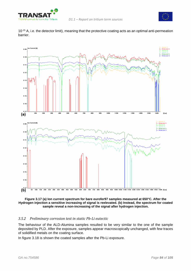
D1.1 – Report on tritium term sources
GA no.754586 Page 84 of 105
10-15 A, i.e. the detector limit), meaning that the protective coating acts as an optimal anti-permeation barrier.
Figure 3.17 (a) Ion current spectrum for bare eurofer97 samples measured at 650°C. After the
Hydrogen injection a sensitive increasing of signal is reelevated. (b) Instead, the spectrum for coated sample reveal a non-increasing of the signal after hydrogen injection.
3.5.2 Preliminary corrosion test in static Pb-Li eutectic The behaviour of the ALD-Alumina samples resulted to be very similar to the one of the sample deposited by PLD. After the exposure, samples appear macroscopically unchanged, with few traces of solidified metals on the coating surface. In figure 3.18 is shown the coated samples after the Pb-Li exposure.
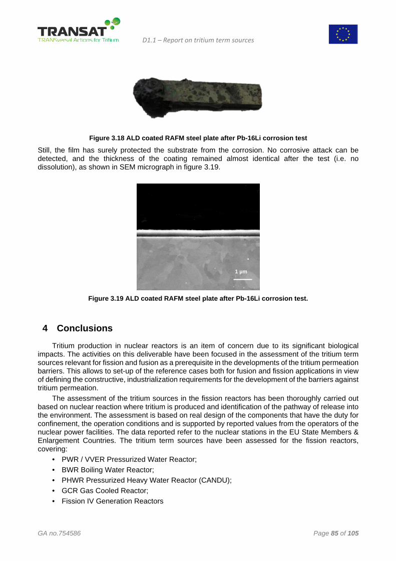
D1.1 – Report on tritium term sources
GA no.754586 Page 85 of 105
Figure 3.18 ALD coated RAFM steel plate after Pb-16Li corrosion test
Still, the film has surely protected the substrate from the corrosion. No corrosive attack can be detected, and the thickness of the coating remained almost identical after the test (i.e. no dissolution), as shown in SEM micrograph in figure 3.19.
Figure 3.19 ALD coated RAFM steel plate after Pb-16Li corrosion test.
4 Conclusions
Tritium production in nuclear reactors is an item of concern due to its significant biological impacts. The activities on this deliverable have been focused in the assessment of the tritium term sources relevant for fission and fusion as a prerequisite in the developments of the tritium permeation barriers. This allows to set-up of the reference cases both for fusion and fission applications in view of defining the constructive, industrialization requirements for the development of the barriers against tritium permeation.
The assessment of the tritium sources in the fission reactors has been thoroughly carried out based on nuclear reaction where tritium is produced and identification of the pathway of release into the environment. The assessment is based on real design of the components that have the duty for confinement, the operation conditions and is supported by reported values from the operators of the nuclear power facilities. The data reported refer to the nuclear stations in the EU State Members & Enlargement Countries. The tritium term sources have been assessed for the fission reactors, covering:
• PWR / VVER Pressurized Water Reactor; • BWR Boiling Water Reactor; • PHWR Pressurized Heavy Water Reactor (CANDU); • GCR Gas Cooled Reactor; • Fission IV Generation Reactors
1 µm
D1.1 – Report on tritium term sources
GA no.754586 Page 86 of 105
As far as fusion is concerned, the assessment of the tritium term source is based on Tokamak option, the magnetic confinement devices with specific characteristics from the ITER and EU-DEMO projects. For such facilities the reduction of tritium source terms remains to be a major task in the development of fusion technology and three areas with significant potentials for improvements have been identified:
• Reduction of tritium inventories in the inner fuel cycle, in the breeder blanket loops, and in the Hot Cell;
• Minimization of tritium migration from primary containments into outer confinement volumes; • Optimization of detritylation and decontamination techniques.
The assessment of the tritium term sources both for fission and fusion provides a sound data base for developments of barriers aiming to mitigate the tritium release into the environment and addressing the followings topics in the R&D programs will be highly beneficial:
1. The assessment of tritium source terms is mainly conducted through systems by systems approach. However, the tritium source terms are also dependent upon operation and maintenance scenarios. Besides the optimization of tritium inventories in the systems, the development of advanced containment and confinement technologies need to be continued. Confinement of tritiated liquids and of gaseous tritium requires a similar approach, i.e. leak tight primary containments and tritium removal from confined volumes as needed. Leak tightness of containments and using appropriate materials is the key issue in the minimization of tritium migration into outer confinement volumes. Further development of self-sustaining and self-healing tritium permeation barriers in cooling water loops appears indispensable.
2. Subjects of major concern for fusion power plants, but not limited to this technology, are the tritium source terms in the cooling loops. Restricting tritium permeation into primary cooling fluids has its limits; keeping the driving force low for tritium permeation into the secondary cooling loops is eventually asking for continuous detritiation of the primary cooling fluids. Particularly in the primary to secondary heat exchanger oxidizing conditions can easily be maintained to keep oxide layers stable and self-healing, thereby providing orders of magnitudes of reduction in tritium permeation fluxes. With additional tritium permeation barriers towards tertiary cooling in the Intermittent Heat Exchanger / Storage the steam generators remain sufficiently uncontaminated. Nevertheless, employment of dry cooling towers instead of wet cooling towers avoid discharging their blow down water with very low but still measurable tritium concentrations.
In order to mitigate the tritium release into environment and tritium inventory in the nuclear power plants, hydrogen isotopes barriers are necessary to kinetically limit the achievement of isotopic thermodynamic equilibrium through hermetic boundaries. On the basis of a literature review carried out two technologies were identified, Pulsed Layer Deposiion (PLD) and Aotmic Layer Deposition (ALD).
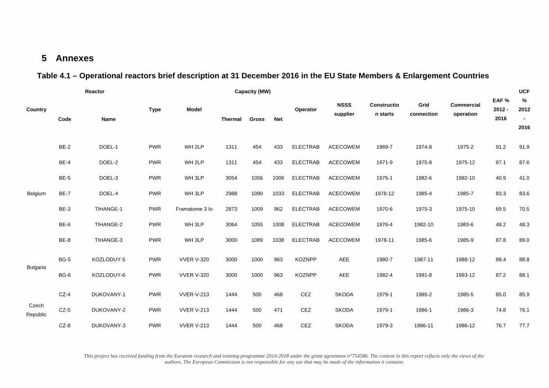
This project has received funding from the Euratom research and training programme 2014-2018 under the grant agreement n°754586. The content in this report reflects only the views of the authors. The European Commission is not responsible for any use that may be made of the information it contains
5 Annexes
Table 4.1 – Operational reactors brief description at 31 December 2016 in the EU State Members & Enlargement Countries
Country
Reactor
Type Model
Capacity (MW)
Operator NSSS
supplier Constructio
n starts Grid
connection Commercial
operation
EAF % 2012 - 2016
UCF %
2012 -
2016 Code Name Thermal Gross Net
Belgium
BE-2
BE-4
BE-5
BE-7
BE-3
BE-6
BE-8
DOEL-1
DOEL-2
DOEL-3
DOEL-4
TIHANGE-1
TIHANGE-2
TIHANGE-3
PWR
PWR
PWR
PWR
PWR
PWR
PWR
WH 2LP
WH 2LP
WH 3LP
WH 3LP
Framatome 3 Io
WH 3LP
WH 3LP
1311
1311
3054
2988
2873
3064
3000
454
454
1056
1090
1009
1055
1089
433
433
1006
1033
962
1008
1038
ELECTRAB
ELECTRAB
ELECTRAB
ELECTRAB
ELECTRAB
ELECTRAB
ELECTRAB
ACECOWEM
ACECOWEM
ACECOWEM
ACECOWEM
ACECOWEM
ACECOWEM
ACECOWEM
1969-7
1971-9
1975-1
1978-12
1970-6
1976-4
1978-11
1974-8
1975-8
1982-6
1985-4
1975-3
1982-10
1985-6
1975-2
1975-12
1982-10
1985-7
1975-10
1983-6
1985-9
91.2
87.1
40.9
83.3
69.5
48.2
87.8
91.9
87.6
41.0
83.6
70.5
48.3
89.0
Bulgaria BG-5
BG-6
KOZLODUY-5
KOZLODUY-6
PWR
PWR
VVER V-320
VVER V-320
3000
3000
1000
1000
963
963
KOZNPP
KOZNPP
AEE
AEE
1980-7
1982-4
1987-11
1991-8
1988-12
1993-12
88.4
87.2
88.8
88.1
Czech
Republic
CZ-4
CZ-5
CZ-8
DUKOVANY-1
DUKOVANY-2
DUKOVANY-3
PWR
PWR
PWR
VVER-V-213
VVER V-213
VVER V-213
1444
1444
1444
500
500
500
468
471
468
CEZ
CEZ
CEZ
SKODA
SKODA
SKODA
1979-1
1979-1
1979-3
1985-2
1986-1
1986-11
1985-5
1986-3
1986-12
85.0
74.8
76.7
85.9
76.1
77.7
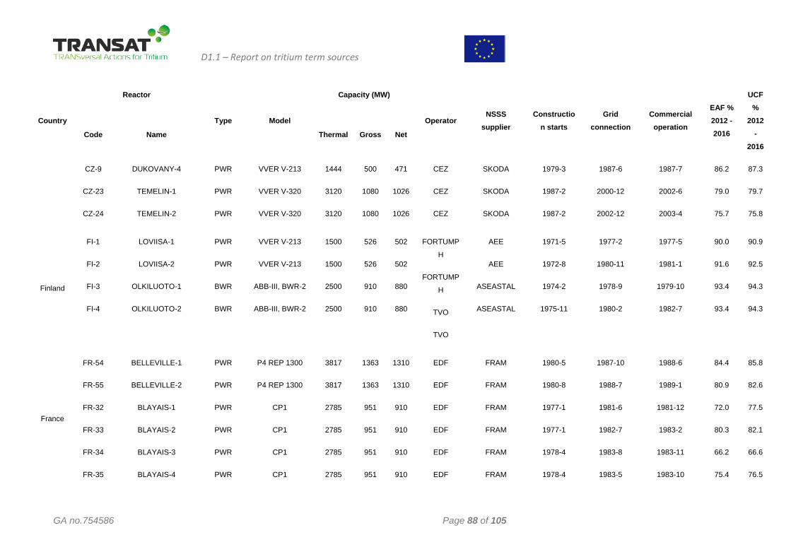
D1.1 – Report on tritium term sources
GA no.754586 Page 88 of 105
Country
Reactor
Type Model
Capacity (MW)
Operator NSSS
supplier Constructio
n starts Grid
connection Commercial
operation
EAF % 2012 - 2016
UCF %
2012 -
2016 Code Name Thermal Gross Net
CZ-9
CZ-23
CZ-24
DUKOVANY-4
TEMELIN-1
TEMELIN-2
PWR
PWR
PWR
VVER V-213
VVER V-320
VVER V-320
1444
3120
3120
500
1080
1080
471
1026
1026
CEZ
CEZ
CEZ
SKODA
SKODA
SKODA
1979-3
1987-2
1987-2
1987-6
2000-12
2002-12
1987-7
2002-6
2003-4
86.2
79.0
75.7
87.3
79.7
75.8
Finland
FI-1
FI-2
FI-3
FI-4
LOVIISA-1
LOVIISA-2
OLKILUOTO-1
OLKILUOTO-2
PWR
PWR
BWR
BWR
VVER V-213
VVER V-213
ABB-III, BWR-2
ABB-III, BWR-2
1500
1500
2500
2500
526
526
910
910
502
502
880
880
FORTUMP
H
FORTUMP
H
TVO
TVO
AEE
AEE
ASEASTAL
ASEASTAL
1971-5
1972-8
1974-2
1975-11
1977-2
1980-11
1978-9
1980-2
1977-5
1981-1
1979-10
1982-7
90.0
91.6
93.4
93.4
90.9
92.5
94.3
94.3
France
FR-54
FR-55
FR-32
FR-33
FR-34
FR-35
BELLEVILLE-1
BELLEVILLE-2
BLAYAIS-1
BLAYAIS-2
BLAYAIS-3
BLAYAIS-4
PWR
PWR
PWR
PWR
PWR
PWR
P4 REP 1300
P4 REP 1300
CP1
CP1
CP1
CP1
3817
3817
2785
2785
2785
2785
1363
1363
951
951
951
951
1310
1310
910
910
910
910
EDF
EDF
EDF
EDF
EDF
EDF
FRAM
FRAM
FRAM
FRAM
FRAM
FRAM
1980-5
1980-8
1977-1
1977-1
1978-4
1978-4
1987-10
1988-7
1981-6
1982-7
1983-8
1983-5
1988-6
1989-1
1981-12
1983-2
1983-11
1983-10
84.4
80.9
72.0
80.3
66.2
75.4
85.8
82.6
77.5
82.1
66.6
76.5
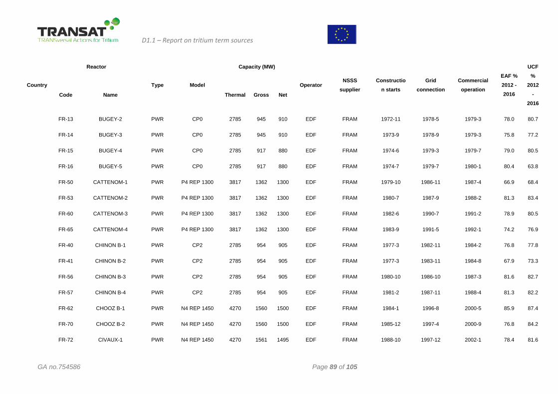
D1.1 – Report on tritium term sources
GA no.754586 Page 89 of 105
Country
Reactor
Type Model
Capacity (MW)
Operator NSSS
supplier Constructio
n starts Grid
connection Commercial
operation
EAF % 2012 - 2016
UCF %
2012 -
2016 Code Name Thermal Gross Net
FR-13
FR-14
FR-15
FR-16
FR-50
FR-53
FR-60
FR-65
FR-40
FR-41
FR-56
FR-57
FR-62
FR-70
FR-72
BUGEY-2
BUGEY-3
BUGEY-4
BUGEY-5
CATTENOM-1
CATTENOM-2
CATTENOM-3
CATTENOM-4
CHINON B-1
CHINON B-2
CHINON B-3
CHINON B-4
CHOOZ B-1
CHOOZ B-2
CIVAUX-1
PWR
PWR
PWR
PWR
PWR
PWR
PWR
PWR
PWR
PWR
PWR
PWR
PWR
PWR
PWR
CP0
CP0
CP0
CP0
P4 REP 1300
P4 REP 1300
P4 REP 1300
P4 REP 1300
CP2
CP2
CP2
CP2
N4 REP 1450
N4 REP 1450
N4 REP 1450
2785
2785
2785
2785
3817
3817
3817
3817
2785
2785
2785
2785
4270
4270
4270
945
945
917
917
1362
1362
1362
1362
954
954
954
954
1560
1560
1561
910
910
880
880
1300
1300
1300
1300
905
905
905
905
1500
1500
1495
EDF
EDF
EDF
EDF
EDF
EDF
EDF
EDF
EDF
EDF
EDF
EDF
EDF
EDF
EDF
FRAM
FRAM
FRAM
FRAM
FRAM
FRAM
FRAM
FRAM
FRAM
FRAM
FRAM
FRAM
FRAM
FRAM
FRAM
1972-11
1973-9
1974-6
1974-7
1979-10
1980-7
1982-6
1983-9
1977-3
1977-3
1980-10
1981-2
1984-1
1985-12
1988-10
1978-5
1978-9
1979-3
1979-7
1986-11
1987-9
1990-7
1991-5
1982-11
1983-11
1986-10
1987-11
1996-8
1997-4
1997-12
1979-3
1979-3
1979-7
1980-1
1987-4
1988-2
1991-2
1992-1
1984-2
1984-8
1987-3
1988-4
2000-5
2000-9
2002-1
78.0
75.8
79.0
80.4
66.9
81.3
78.9
74.2
76.8
67.9
81.6
81.3
85.9
76.8
78.4
80.7
77.2
80.5
63.8
68.4
83.4
80.5
76.9
77.8
73.3
82.7
82.2
87.4
84.2
81.6
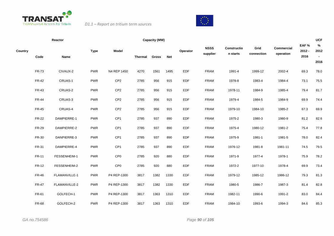
D1.1 – Report on tritium term sources
GA no.754586 Page 90 of 105
Country
Reactor
Type Model
Capacity (MW)
Operator NSSS
supplier Constructio
n starts Grid
connection Commercial
operation
EAF % 2012 - 2016
UCF %
2012 -
2016 Code Name Thermal Gross Net
FR-73
FR-42
FR-43
FR-44
FR-45
FR-22
FR-29
FR-30
FR-31
FR-11
FR-12
FR-46
FR-47
FR-61
FR-68
CIVAUX-2
CRUAS-1
CRUAS-2
CRUAS-3
CRUAS-4
DAMPIERRE-1
DAMPIERRE-2
DANPIERRE-3
DAMPIERRE-4
FESSENHEIM-1
FESSENHEIM-2
FLAMANVILLE-1
FLAMANVILLE-2
GOLFECH-1
GOLFECH-2
PWR
PWR
PWR
PWR
PWR
PWR
PWR
PWR
PWR
PWR
PWR
PWR
PWR
PWR
PWR
N4 REP 1450
CP2
CP2
CP2
CP2
CP1
CP1
CP1
CP1
CP0
CP0
P4 REP-1300
P4 REP-1300
P4 REP-1300
P4 REP-1300
4270
2785
2785
2785
2785
2785
2785
2785
2785
2785
2785
3817
3817
3817
3817
1561
956
956
956
956
937
937
937
937
920
920
1382
1382
1363
1363
1495
915
915
915
915
890
890
890
890
880
880
1330
1330
1310
1310
EDF
EDF
EDF
EDF
EDF
EDF
EDF
EDF
EDF
EDF
EDF
EDF
EDF
EDF
EDF
FRAM
FRAM
FRAM
FRAM
FRAM
FRAM
FRAM
FRAM
FRAM
FRAM
FRAM
FRAM
FRAM
FRAM
FRAM
1991-4
1978-8
1978-11
1979-4
1979-10
1975-2
1975-4
1975-9
1976-12
1971-9
1972-2
1979-12
1980-5
1982-11
1984-10
1999-12
1983-4
1984-9
1984-5
1984-10
1980-3
1980-12
1981-1
1981-8
1977-4
1977-10
1985-12
1986-7
1990-6
1993-6
2002-4
1984-4
1985-4
1984-9
1985-2
1980-9
1981-2
1981-5
1981-11
1978-1
1978-4
1986-12
1987-3
1991-2
1994-3
69.3
73.1
79.4
69.9
67.3
81.2
75.4
78.0
74.5
75.9
69.9
79.3
81.4
83.0
84.6
78.0
75.5
81.7
74.4
69.9
82.6
77.8
82.4
79.5
78.2
73.4
81.3
82.8
84.4
85.3
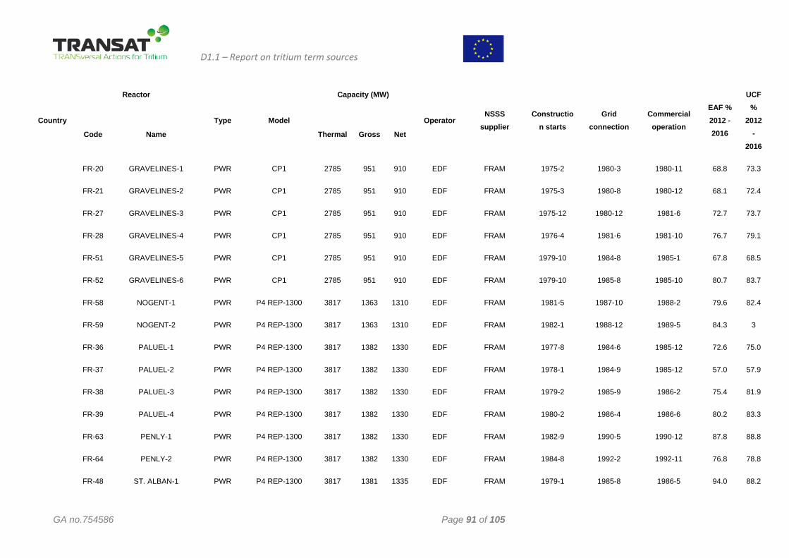
D1.1 – Report on tritium term sources
GA no.754586 Page 91 of 105
Country
Reactor
Type Model
Capacity (MW)
Operator NSSS
supplier Constructio
n starts Grid
connection Commercial
operation
EAF % 2012 - 2016
UCF %
2012 -
2016 Code Name Thermal Gross Net
FR-20
FR-21
FR-27
FR-28
FR-51
FR-52
FR-58
FR-59
FR-36
FR-37
FR-38
FR-39
FR-63
FR-64
FR-48
GRAVELINES-1
GRAVELINES-2
GRAVELINES-3
GRAVELINES-4
GRAVELINES-5
GRAVELINES-6
NOGENT-1
NOGENT-2
PALUEL-1
PALUEL-2
PALUEL-3
PALUEL-4
PENLY-1
PENLY-2
ST. ALBAN-1
PWR
PWR
PWR
PWR
PWR
PWR
PWR
PWR
PWR
PWR
PWR
PWR
PWR
PWR
PWR
CP1
CP1
CP1
CP1
CP1
CP1
P4 REP-1300
P4 REP-1300
P4 REP-1300
P4 REP-1300
P4 REP-1300
P4 REP-1300
P4 REP-1300
P4 REP-1300
P4 REP-1300
2785
2785
2785
2785
2785
2785
3817
3817
3817
3817
3817
3817
3817
3817
3817
951
951
951
951
951
951
1363
1363
1382
1382
1382
1382
1382
1382
1381
910
910
910
910
910
910
1310
1310
1330
1330
1330
1330
1330
1330
1335
EDF
EDF
EDF
EDF
EDF
EDF
EDF
EDF
EDF
EDF
EDF
EDF
EDF
EDF
EDF
FRAM
FRAM
FRAM
FRAM
FRAM
FRAM
FRAM
FRAM
FRAM
FRAM
FRAM
FRAM
FRAM
FRAM
FRAM
1975-2
1975-3
1975-12
1976-4
1979-10
1979-10
1981-5
1982-1
1977-8
1978-1
1979-2
1980-2
1982-9
1984-8
1979-1
1980-3
1980-8
1980-12
1981-6
1984-8
1985-8
1987-10
1988-12
1984-6
1984-9
1985-9
1986-4
1990-5
1992-2
1985-8
1980-11
1980-12
1981-6
1981-10
1985-1
1985-10
1988-2
1989-5
1985-12
1985-12
1986-2
1986-6
1990-12
1992-11
1986-5
68.8
68.1
72.7
76.7
67.8
80.7
79.6
84.3
72.6
57.0
75.4
80.2
87.8
76.8
94.0
73.3
72.4
73.7
79.1
68.5
83.7
82.4
3
75.0
57.9
81.9
83.3
88.8
78.8
88.2
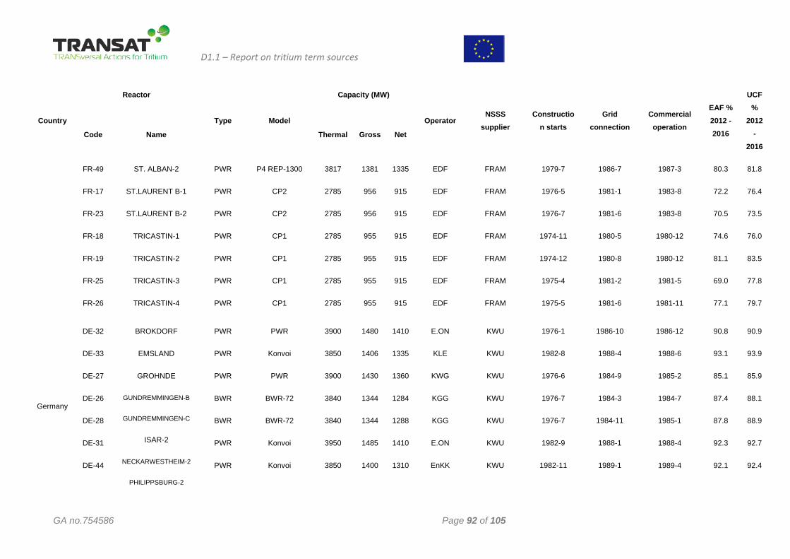
D1.1 – Report on tritium term sources
GA no.754586 Page 92 of 105
Country
Reactor
Type Model
Capacity (MW)
Operator NSSS
supplier Constructio
n starts Grid
connection Commercial
operation
EAF % 2012 - 2016
UCF %
2012 -
2016 Code Name Thermal Gross Net
FR-49
FR-17
FR-23
FR-18
FR-19
FR-25
FR-26
ST. ALBAN-2
ST.LAURENT B-1
ST.LAURENT B-2
TRICASTIN-1
TRICASTIN-2
TRICASTIN-3
TRICASTIN-4
PWR
PWR
PWR
PWR
PWR
PWR
PWR
P4 REP-1300
CP2
CP2
CP1
CP1
CP1
CP1
3817
2785
2785
2785
2785
2785
2785
1381
956
956
955
955
955
955
1335
915
915
915
915
915
915
EDF
EDF
EDF
EDF
EDF
EDF
EDF
FRAM
FRAM
FRAM
FRAM
FRAM
FRAM
FRAM
1979-7
1976-5
1976-7
1974-11
1974-12
1975-4
1975-5
1986-7
1981-1
1981-6
1980-5
1980-8
1981-2
1981-6
1987-3
1983-8
1983-8
1980-12
1980-12
1981-5
1981-11
80.3
72.2
70.5
74.6
81.1
69.0
77.1
81.8
76.4
73.5
76.0
83.5
77.8
79.7
Germany
DE-32
DE-33
DE-27
DE-26
DE-28
DE-31
DE-44
BROKDORF
EMSLAND
GROHNDE
GUNDREMMINGEN-B
GUNDREMMINGEN-C
ISAR-2
NECKARWESTHEIM-2
PHILIPPSBURG-2
PWR
PWR
PWR
BWR
BWR
PWR
PWR
PWR
Konvoi
PWR
BWR-72
BWR-72
Konvoi
Konvoi
3900
3850
3900
3840
3840
3950
3850
1480
1406
1430
1344
1344
1485
1400
1410
1335
1360
1284
1288
1410
1310
E.ON
KLE
KWG
KGG
KGG
E.ON
EnKK
KWU
KWU
KWU
KWU
KWU
KWU
KWU
1976-1
1982-8
1976-6
1976-7
1976-7
1982-9
1982-11
1986-10
1988-4
1984-9
1984-3
1984-11
1988-1
1989-1
1986-12
1988-6
1985-2
1984-7
1985-1
1988-4
1989-4
90.8
93.1
85.1
87.4
87.8
92.3
92.1
90.9
93.9
85.9
88.1
88.9
92.7
92.4
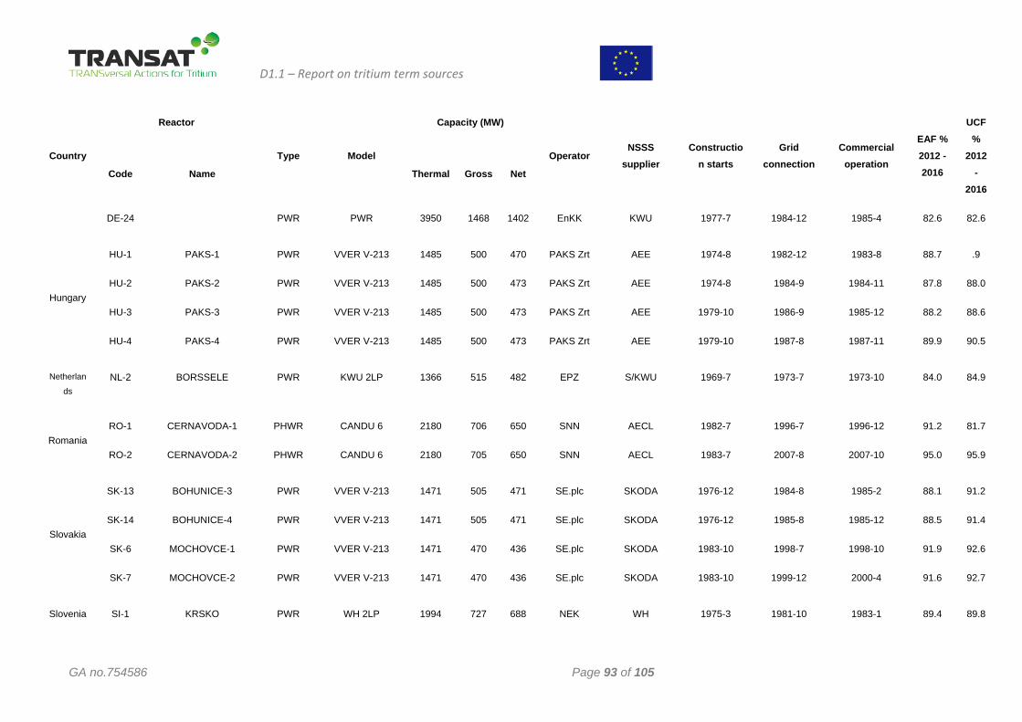
D1.1 – Report on tritium term sources
GA no.754586 Page 93 of 105
Country
Reactor
Type Model
Capacity (MW)
Operator NSSS
supplier Constructio
n starts Grid
connection Commercial
operation
EAF % 2012 - 2016
UCF %
2012 -
2016 Code Name Thermal Gross Net
DE-24 PWR PWR 3950 1468 1402 EnKK KWU 1977-7 1984-12 1985-4 82.6 82.6
Hungary
HU-1
HU-2
HU-3
HU-4
PAKS-1
PAKS-2
PAKS-3
PAKS-4
PWR
PWR
PWR
PWR
VVER V-213
VVER V-213
VVER V-213
VVER V-213
1485
1485
1485
1485
500
500
500
500
470
473
473
473
PAKS Zrt
PAKS Zrt
PAKS Zrt
PAKS Zrt
AEE
AEE
AEE
AEE
1974-8
1974-8
1979-10
1979-10
1982-12
1984-9
1986-9
1987-8
1983-8
1984-11
1985-12
1987-11
88.7
87.8
88.2
89.9
.9
88.0
88.6
90.5
Netherlan
ds NL-2 BORSSELE PWR KWU 2LP 1366 515 482 EPZ S/KWU 1969-7 1973-7 1973-10 84.0 84.9
Romania RO-1
RO-2
CERNAVODA-1
CERNAVODA-2
PHWR
PHWR
CANDU 6
CANDU 6
2180
2180
706
705
650
650
SNN
SNN
AECL
AECL
1982-7
1983-7
1996-7
2007-8
1996-12
2007-10
91.2
95.0
81.7
95.9
Slovakia
SK-13
SK-14
SK-6
SK-7
BOHUNICE-3
BOHUNICE-4
MOCHOVCE-1
MOCHOVCE-2
PWR
PWR
PWR
PWR
VVER V-213
VVER V-213
VVER V-213
VVER V-213
1471
1471
1471
1471
505
505
470
470
471
471
436
436
SE.plc
SE.plc
SE.plc
SE.plc
SKODA
SKODA
SKODA
SKODA
1976-12
1976-12
1983-10
1983-10
1984-8
1985-8
1998-7
1999-12
1985-2
1985-12
1998-10
2000-4
88.1
88.5
91.9
91.6
91.2
91.4
92.6
92.7
Slovenia SI-1 KRSKO PWR WH 2LP 1994 727 688 NEK WH 1975-3 1981-10 1983-1 89.4 89.8
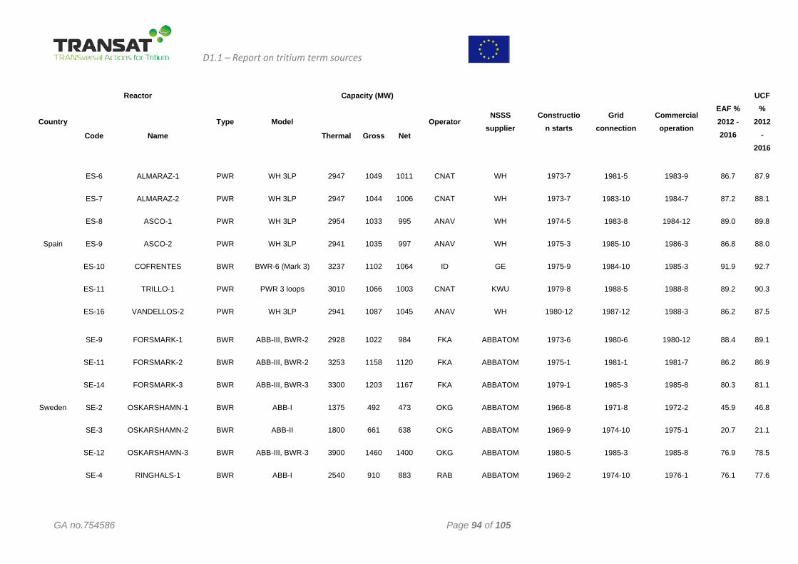
D1.1 – Report on tritium term sources
GA no.754586 Page 94 of 105
Country
Reactor
Type Model
Capacity (MW)
Operator NSSS
supplier Constructio
n starts Grid
connection Commercial
operation
EAF % 2012 - 2016
UCF %
2012 -
2016 Code Name Thermal Gross Net
Spain
ES-6
ES-7
ES-8
ES-9
ES-10
ES-11
ES-16
ALMARAZ-1
ALMARAZ-2
ASCO-1
ASCO-2
COFRENTES
TRILLO-1
VANDELLOS-2
PWR
PWR
PWR
PWR
BWR
PWR
PWR
WH 3LP
WH 3LP
WH 3LP
WH 3LP
BWR-6 (Mark 3)
PWR 3 loops
WH 3LP
2947
2947
2954
2941
3237
3010
2941
1049
1044
1033
1035
1102
1066
1087
1011
1006
995
997
1064
1003
1045
CNAT
CNAT
ANAV
ANAV
ID
CNAT
ANAV
WH
WH
WH
WH
GE
KWU
WH
1973-7
1973-7
1974-5
1975-3
1975-9
1979-8
1980-12
1981-5
1983-10
1983-8
1985-10
1984-10
1988-5
1987-12
1983-9
1984-7
1984-12
1986-3
1985-3
1988-8
1988-3
86.7
87.2
89.0
86.8
91.9
89.2
86.2
87.9
88.1
89.8
88.0
92.7
90.3
87.5
Sweden
SE-9
SE-11
SE-14
SE-2
SE-3
SE-12
SE-4
FORSMARK-1
FORSMARK-2
FORSMARK-3
OSKARSHAMN-1
OSKARSHAMN-2
OSKARSHAMN-3
RINGHALS-1
BWR
BWR
BWR
BWR
BWR
BWR
BWR
ABB-III, BWR-2
ABB-III, BWR-2
ABB-III, BWR-3
ABB-I
ABB-II
ABB-III, BWR-3
ABB-I
2928
3253
3300
1375
1800
3900
2540
1022
1158
1203
492
661
1460
910
984
1120
1167
473
638
1400
883
FKA
FKA
FKA
OKG
OKG
OKG
RAB
ABBATOM
ABBATOM
ABBATOM
ABBATOM
ABBATOM
ABBATOM
ABBATOM
1973-6
1975-1
1979-1
1966-8
1969-9
1980-5
1969-2
1980-6
1981-1
1985-3
1971-8
1974-10
1985-3
1974-10
1980-12
1981-7
1985-8
1972-2
1975-1
1985-8
1976-1
88.4
86.2
80.3
45.9
20.7
76.9
76.1
89.1
86.9
81.1
46.8
21.1
78.5
77.6
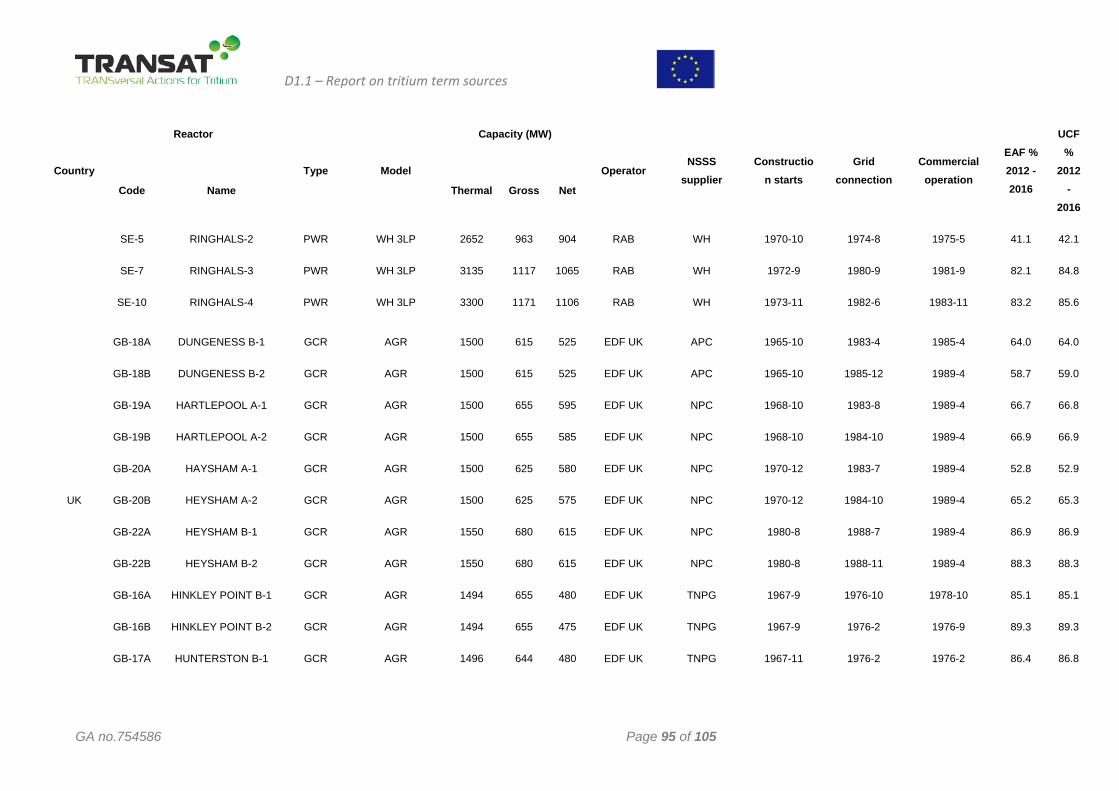
D1.1 – Report on tritium term sources
GA no.754586 Page 95 of 105
Country
Reactor
Type Model
Capacity (MW)
Operator NSSS
supplier Constructio
n starts Grid
connection Commercial
operation
EAF % 2012 - 2016
UCF %
2012 -
2016 Code Name Thermal Gross Net
SE-5
SE-7
SE-10
RINGHALS-2
RINGHALS-3
RINGHALS-4
PWR
PWR
PWR
WH 3LP
WH 3LP
WH 3LP
2652
3135
3300
963
1117
1171
904
1065
1106
RAB
RAB
RAB
WH
WH
WH
1970-10
1972-9
1973-11
1974-8
1980-9
1982-6
1975-5
1981-9
1983-11
41.1
82.1
83.2
42.1
84.8
85.6
UK
GB-18A
GB-18B
GB-19A
GB-19B
GB-20A
GB-20B
GB-22A
GB-22B
GB-16A
GB-16B
GB-17A
DUNGENESS B-1
DUNGENESS B-2
HARTLEPOOL A-1
HARTLEPOOL A-2
HAYSHAM A-1
HEYSHAM A-2
HEYSHAM B-1
HEYSHAM B-2
HINKLEY POINT B-1
HINKLEY POINT B-2
HUNTERSTON B-1
GCR
GCR
GCR
GCR
GCR
GCR
GCR
GCR
GCR
GCR
GCR
AGR
AGR
AGR
AGR
AGR
AGR
AGR
AGR
AGR
AGR
AGR
1500
1500
1500
1500
1500
1500
1550
1550
1494
1494
1496
615
615
655
655
625
625
680
680
655
655
644
525
525
595
585
580
575
615
615
480
475
480
EDF UK
EDF UK
EDF UK
EDF UK
EDF UK
EDF UK
EDF UK
EDF UK
EDF UK
EDF UK
EDF UK
APC
APC
NPC
NPC
NPC
NPC
NPC
NPC
TNPG
TNPG
TNPG
1965-10
1965-10
1968-10
1968-10
1970-12
1970-12
1980-8
1980-8
1967-9
1967-9
1967-11
1983-4
1985-12
1983-8
1984-10
1983-7
1984-10
1988-7
1988-11
1976-10
1976-2
1976-2
1985-4
1989-4
1989-4
1989-4
1989-4
1989-4
1989-4
1989-4
1978-10
1976-9
1976-2
64.0
58.7
66.7
66.9
52.8
65.2
86.9
88.3
85.1
89.3
86.4
64.0
59.0
66.8
66.9
52.9
65.3
86.9
88.3
85.1
89.3
86.8
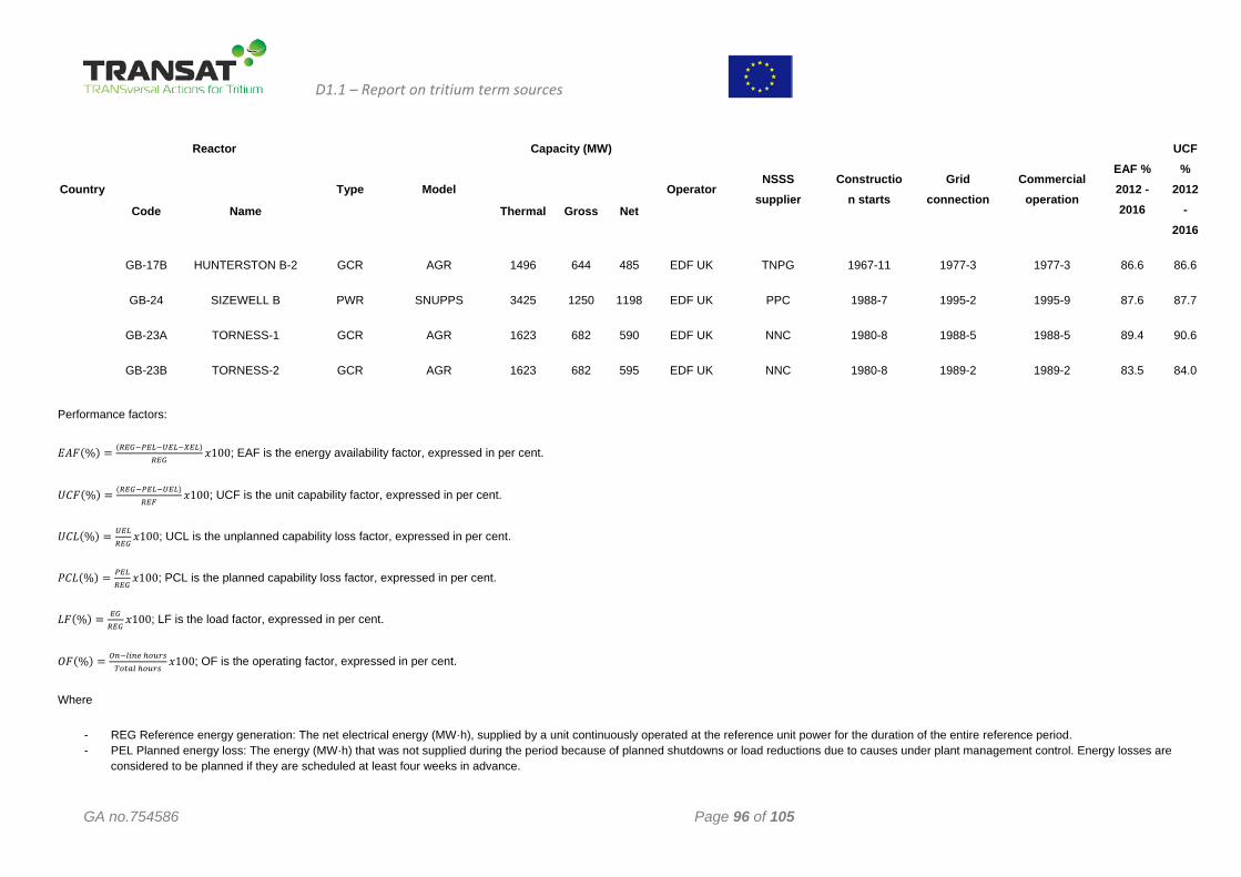
D1.1 – Report on tritium term sources
GA no.754586 Page 96 of 105
Country
Reactor
Type Model
Capacity (MW)
Operator NSSS
supplier Constructio
n starts Grid
connection Commercial
operation
EAF % 2012 - 2016
UCF %
2012 -
2016 Code Name Thermal Gross Net
GB-17B
GB-24
GB-23A
GB-23B
HUNTERSTON B-2
SIZEWELL B
TORNESS-1
TORNESS-2
GCR
PWR
GCR
GCR
AGR
SNUPPS
AGR
AGR
1496
3425
1623
1623
644
1250
682
682
485
1198
590
595
EDF UK
EDF UK
EDF UK
EDF UK
TNPG
PPC
NNC
NNC
1967-11
1988-7
1980-8
1980-8
1977-3
1995-2
1988-5
1989-2
1977-3
1995-9
1988-5
1989-2
86.6
87.6
89.4
83.5
86.6
87.7
90.6
84.0
Performance factors:
𝐸𝐸𝐴𝐴𝑃𝑃(%) = (𝑅𝑅𝐸𝐸𝑅𝑅−𝑃𝑃𝐸𝐸𝐿𝐿−𝑈𝑈𝐸𝐸𝐿𝐿−𝑋𝑋𝐸𝐸𝐿𝐿)𝑅𝑅𝐸𝐸𝑅𝑅
𝑒𝑒100; EAF is the energy availability factor, expressed in per cent.
𝑈𝑈𝐶𝐶𝑃𝑃(%) = (𝑅𝑅𝐸𝐸𝑅𝑅−𝑃𝑃𝐸𝐸𝐿𝐿−𝑈𝑈𝐸𝐸𝐿𝐿)𝑅𝑅𝐸𝐸𝑅𝑅
𝑒𝑒100; UCF is the unit capability factor, expressed in per cent.
𝑈𝑈𝐶𝐶𝐿𝐿(%) = 𝑈𝑈𝐸𝐸𝐿𝐿𝑅𝑅𝐸𝐸𝑅𝑅
𝑒𝑒100; UCL is the unplanned capability loss factor, expressed in per cent.
𝑃𝑃𝐶𝐶𝐿𝐿(%) = 𝑃𝑃𝐸𝐸𝐿𝐿𝑅𝑅𝐸𝐸𝑅𝑅
𝑒𝑒100; PCL is the planned capability loss factor, expressed in per cent.
𝐿𝐿𝑃𝑃(%) = 𝐸𝐸𝑅𝑅𝑅𝑅𝐸𝐸𝑅𝑅
𝑒𝑒100; LF is the load factor, expressed in per cent.
𝑂𝑂𝑃𝑃(%) = 𝑂𝑂𝑡𝑡−𝑙𝑙𝐶𝐶𝑡𝑡𝑡𝑡 ℎ𝑡𝑡𝑜𝑜𝑡𝑡𝑠𝑠𝑇𝑇𝑡𝑡𝜆𝜆𝑇𝑇𝑙𝑙 ℎ𝑡𝑡𝑜𝑜𝑡𝑡𝑠𝑠
𝑒𝑒100; OF is the operating factor, expressed in per cent.
Where
- REG Reference energy generation: The net electrical energy (MW·h), supplied by a unit continuously operated at the reference unit power for the duration of the entire reference period. - PEL Planned energy loss: The energy (MW·h) that was not supplied during the period because of planned shutdowns or load reductions due to causes under plant management control. Energy losses are
considered to be planned if they are scheduled at least four weeks in advance.
D1.1 – Report on tritium term sources
GA no.754586 Page 97 of 105
Country
Reactor
Type Model
Capacity (MW)
Operator NSSS
supplier Constructio
n starts Grid
connection Commercial
operation
EAF % 2012 - 2016
UCF %
2012 -
2016 Code Name Thermal Gross Net
- UEL Unplanned energy loss: The energy (MW·h) that was not supplied during the period because of unplanned shutdowns, outage extensions, or load reductions due to causes under plant management control. Energy losses are considered to be unplanned if they are not scheduled at least four weeks in advance.
- XEL External energy loss: The energy (MW·h) that was not supplied owing to constraints beyond plant management control that reduced plant availability. - EG: The net electrical energy supplied during the reference period as measured at the unit outlet terminals after deducting the electrical energy taken by unit auxiliaries and the losses in transformers that are
considered to be integral parts of the unit.
This project has received funding from the Euratom research and training programme 2014-2018 under the grant agreement n°754586. The content in this report reflects only the views of the authors. The European Commission
is not responsible for any use that may be made of the information it contains
6 References
[1] * * - Nuclear Power Reactors in the World, Reference data series no. 2, International Atomic Energy Agency, 2017 Edition [2] * * - Nuclear Engineering Handbook. Second Edition, edited by Kenneth D. Kok, CRC Press, Taylor & Francis Group, 2016 [3] Tritium handling and safe storage DOE-1129-2008 - December 2008 [4] Radioactive Effluents from Nuclear Power Plants – U.S.NRC NUREG/CR-2907, Vol. 15 [5] OPEXs of Wolsong TRF – Presentation Korea Hydro & Nuclear Power Co.,LTD September 2014 [6] Cernavoda Tritium Removal Facility SAFETY DESIGN GUIDE - CANDESCO No. KI CTRF- 00402-2, July 16, 2014 [7] Studiu de fezabilitate Instalatie de detritiere CNE Cernavoda -79-38500-SF-001 rev. 10. [8] Darlington Tritium Removal Facility Presentation to Wolsong TRF, Thomas Wong, September 2014 [9] Babcock & Wilcox Canada – Cernavoda Steam Generators Design - Project No. 7505/7506. [10] Babcock & Wilcox Canada – Cernavoda Moderator heat exchanger- Project No. 7507 [11] CITON – Schimbator de caldura 3221-HX1- Project No.2-2-32211-1-1-BD [12] Babcock & Wilcox Canada – Cernavoda Shutdown cooler- Project No. 7508 [13] Babcock & Wilcox Canada – Cernavoda Purification cooler - Project No. 7509 [14] Babcock & Wilcox Canada – Cernavoda Degasser cooler - Project No. 7510 [15] CITON -Design Manual - Main Moderator System - No. 82-32110-6005-DM [16] CITON -Design Manual - Primary Heat transport system -No. 82-33100-6001-DM [17] The Essential CANDU , Editor-in-Chief: Wm. J. Garland, Professor Emeritus, McMaster University, Hamilton, Ontario - 2014 [18] Tim Abram, Sue Ion, Generation-IV nuclear power, A review of the state of the science, Energy Policy 36, pp. 4323-4330, 2008 [19] SNEPT–ESNII-European Sustainable Nuclear Industrial Initiative – A contribution to the EU Low Carbon, Energy policy – The Demonstration Program for Fast Neutrons Reactors, “Concept paper” d’octobre 2010 [20] Hideki KAMIDE, Sodium Fast Reactor “Internatonal Workshop on Advanced Reactor Systems and Future Energy Market Needs” (Apr. 12, 2017 OECD Conference Centre, Paris, France [21] V.V. Alexseev, S.V.Zabrodskaia, K.V.Tykleeva, A.G.Tsikunov, The method of calculating tritium content in various technological media of BN-type reactors, IAEA-CN245-459 [22] J.E. Tanner, An Overview of Tritium Fast Fission Yields, U.S. Department of Energy, Contract DE-AC06-76RLO 1830, 1981 [23] Luciano Cinotti, M.E. Revus, Overview of Nuclear Power Plant, Madrid, 11-June, 2012 [24] E. Franza, A. Ciampichetti, M. Zucchetti, Analisi del trasporto del trizio nei sistemi SFR [25] ASN « Livre blanc du tritium » 2014 (http://www.asn.fr/sites/tritium/) [26] Christian Latgé, L. Brissonneau, Th. Gilardi, Coolants in Fast Neutron Spectrum Systems, IAEA Vienna International Center, Vienna, Austria 5th -7th July 2017 [28] T.A. Renner and C.C. McPheeters, Tritium and Hydrogen Transport in LMFBR Systems, ANL-78-64, September 1978 [29] Buzzelli et al., 1976; Buzzelli and Langer, 1977 [30] ENDF/BIV Library ENDG/BIV library-tapes 401-411 and 414-419,National Neutron Cross Section Center, Brookhaven National Laboratory (December 1974) [31] F.A. Cafasso et.al. Chemical engineering Division Reactor Fuels and Materials Chemistry Research, Argonne National Laboratory, July 1976-September 1977 [32] Eung S. Kim, Chang H. Oh, Mike Patterson, Development of Tritium Permeation Analysis Code and Tritium transport In a High Temperature Gas, Proceeding of ICAPP’10, San
D1.1 – Report on tritium term sources
GA no.754586 Page 99 of 105
Diego, CA, USA, June 13-17, 2010 [33] J. E. Phillips, C. E. Easterly, Sources of Tritium, OAK RIDE NATIONAL LABORATORY, December, 1980 [34] Jianzhu Cao, Liguo Zhang, Feng Xie, Bing Xia, and Stephen Tang Lam, Source Term Study on Tritium in HTR-PM:Theoretical Calculations and Experimental Design, Science and Technology of Nuclear Installations, Volume 2017, Article ID 3586723, 11 pages [35] Timothy Flaspoehlera and Bojan Petrovic, Assessing Pathways to Tritium Production and its Detailed Spatial Distribution Throughout the VHTR, EPJ Web of Conferences 106, 03005 (2016) [36] Michael A. Fütterer, Elio D'Agata, Xavier Raepsaet, Is Tritium an Issue for High Temperature Reactors, Proceedings of HTR 2014 Weihai, China, October 27-31, 2014 [37] A.M.Nolon, An Overview of Environmental Control Aspects for the Gas Cooled Fast Reactor, May 1981 [39] * * * - Discharges from boiling water reactors A review of available discharge data, Environment Agency, UK, July 2016 [40] Daniela Elena Gugiu, Şerban Constantin Valeca, Florin Cosmin Bortosu – Isotopic inventory evaluations in lead-cooled fast reactors, Journal of nuclear research and development, no. 15, May 2018. [41] Internation Atomic Energy Agency. Liquid Metal Cooled Reactors: Experience in Design and Operation. December 2007. ISBN 978–92–0–107907–7. [42] ITER Organization 2016 Annual Report. [43] A. Loarte, private communication: The ITER Research Plan, 05/2018. [44] I. S. Carvalho, D. Wilson, T. Keenan, R. Felton, E. Belonohy, J. Banks, S. Omolayo, A. C.
C. Sips, D. Price, P. Camp, S. Knipe, S. Medley, “Operational aspects of the JET tritium introduction modules”, Fusion Eng. Design 124, 841-845 (2017). [45] W. Wayt Gibbs, Spektrum der Wissenschaft 2.2017, “Kernfusion einmal anders”, 60-68. [46] M. M. Waldrop, “The Fusion Upstarts”, Nature 511, 398-400 (2014). [47] C Gliss, S. Ciattaglia, W Korn, I. Moscato, “Initial layout of DEMO buildings and Configuration of the main plant systems”, Fusion Eng. Design, in press (2018). [48] T. Delaforge, European ITER Site Studies (EISS), Task SL 53.7 “Guide for a transposition from recommended ventilation configurations for aerosol in ISO 17873 standard to means adapted for tritium”, 2006. [49] Y. Asada, “Japanese Activities Concerning Nuclear Codes and Standards”, J. Pressure Vessel Technol. 128 (1), 64-70 (2005). [50] N. Taylor, S. Ciattaglia, P. Cortes, M. Iseli, S. Rosanvallon, L. Topilski, “ITER safety and licensing update”, Fusion Eng. Design 87, 476-481, (2012). [51] ISO 17873, First edition 2004-10-15. [52] A. N. Perevezentsev, A. C. Bell, B. M. Andreev, M. B. Rozenkevich, Y. S. Pak, A. V.
Ovcharov, “Wet Scrubber Column for Air Detritiation”, Fusion Sci. Technol. 56, 1455- 1461,(2009).
[53] A. N .Perevezentsev, B. M. Andreev, M. B. Rozenkevich, Y. S. Pak, A. V. Ovcharov, S. A. Marunich, “Wet scrubber technology for tritium confinement at ITER”, Fusion Eng & Design 85, 1206-1210 (2010).
[54] M. Glugla, A. Antipenkov, S. Beloglazov, C. Caldwell-Nichols, I. R. Cristescu, I. Cristescu, C. Day, L. Doerr, J. P. Girard, E. Tada, “The ITER tritium systems”, Fusion
Eng. Design 82, 472-487 (2007). [55] N. Taylor, C. Alejaldre, P. Cortes, “Progress in the Safety and Licensing for ITER”, Fusion
Sci. Technol. 64, 111-117, (2013). [56] M. Glugla, R. Lässer, L. Dörr, D. K. Murdoch, R. Haange, H. Yoshida, “The inner deuterium/tritium fuel cycle of ITER”, Fusion Eng. Design 69, 39-43 (2003). [57] A. Frattolillo, L. R. Baylor, F. Bombarda, S. K. Combs, C. Day, P. T. Lang, S. Migliori, B. Pégourié, B. Ploeckl, “Core Fueling of DEMO by Direct Line Injection of High-Speed Pellets From the HFS”, IEEE Trans. Plasma Sci. 46, 1429 – 1435 (2018 ).
D1.1 – Report on tritium term sources
GA no.754586 Page 100 of 105
[58] M. E. Sawan, M. A. Abdou, “Physics and technology conditions for attaining tritium self- sufficiency for the DT fuel cycle”, Fusion Eng. Design 81, 1131-1144, (2006). [59] J. Ongena, R. Koch, Y. O. Kazakov, N. Bekris, D. Mazon, “The Big Step from ITER to DEMO”, 12th Carolus Magnus Summer School on Plasma and Fusion Energy Physics, Leuven, Belgium; Energy & Environment Volume 298, 442-456, (2015), ISBN 978 3 95806-107-1. [60] M. Abdou, “Overview of the Tritium Fuel Cycle and Conditions for Tritium Fuel Self- Sufficiency and Other Tritium Issues”, 4th IAEA DEMO Programme Workshop, Karlsruhe, (Germany) November 15th-18th, 2016. [61] L. M. Giancarli, M. Abdou, D. J. Campbell, V. A. Chuyanov, M. Y. Ahn, M. Enoeda, C Pan, Y. Poitevin, E. Rajendra Kumar, I. Ricapito, Y. Strebkov, S. Suzuki, P. C. Wong, M. Zmitko, “Overview of the ITER TBM Program”, Fusion Eng. Design 87, 395-402 (2012). [62] D. Demange, R. Antunes, O. Borisevich, L. Frances, D. Rapisarda, A. Santucci, M. Utili. “Tritium extraction technologies and DEMO requirements”, Fusion Eng. Design 109 111, 912-916 (2016). [63] S. Willms, et. al., “Mathematical Comparison of Three Tritium System Effluent HTO Cleanup Systems”, Fus. Sci. Technol. 41, 974 (2002). [64] Y. Iwai, private communication 2015. [65] I. Cristescu, I. R .Cristescu, L. Dörr, M. Glugla, D. Murdoch, S. Welte, “Long term performances assessment of a water detritiation system components”, Fusion Eng. Design 81, 839-844 (2006). [66] R. G. Ana, I Cristescu, L. Dörr, R. Michling, S. Welte, W. Wurster, I. Cristescu, “Design and experimental activities in view of Water Detritiation–Isotopic Separation Systems combination in TRENTA facility”, Fusion Eng. Design 84, 398-403 (2009). [67] I. Cristescu, I. R. Cristescu, U. Tamm, C. J. Caldwell-Nichols, M. Glugla, D. Murdoch, S. Welte, “Simultaneous tritium and deuterium transfer in a water detritiation CECE facility at TLK”, Fusion Eng. Design 69, 109-113 (2003). [68] N. Taylor, D. Baker, S. Ciattaglia, P. Cortes, J. Elbez-Uzan, M. Iseli, S. Reyes, L. Rodriguez Rodrigo, S. Rosanvallon, L. Topilski, “Updated safety analysis of ITER”, Fusion Eng.Design 86, 619-622 (2011). [69] A. Caravella, S. Hara, E. Drioli, G. Barbieri, “Sieverts law pressure exponent for hydrogen permeation through Pd-based membranes: Coupled influence of non-ideal diffusion and multicomponent external mass transfer”, Int. J. of Hydrogen Energy 38, 16229-16244 (2013). [70] B. Bornschein, C. Day, D. Demange, T. Pinna, “Tritium management and safety issues in ITER and DEMO breeding blankets”, Fusion Eng. Design 88, 466–471 (2013). [71] T. Hayashi, T. Itoh, K. Kobayashi, K. Isobe, M. Nishi, “Safety handling characteristics of high-level tritiated water”, Fusion Eng. Design 81, 1365-1369 (2006). [72] T. Otsuka, K. Hashizume “Behavior of Tritium permeation induced by water corrosion of α iron around room temperature”, Fusion Sci. Technol. 67 (3), 511-514. [73] H. Nakamura, M. Nishi, “Experimental evaluation of tritium permeation through stainless steel tubes of heat exchanger from primary to secondary water in ITER”, J. Nucl. Mat. 329–333 (2004) 183–187. [74] H. D. Röhrig, R. Hecker, J. Blumensaat, J. Schaefer, “Studies on the Permeation of Hydrogen and Tritium in Nuclear Process Heat Installations”, Nucl. Eng. Design 34, 157 167, (1975). [75] A. S. Schmidt, F. Verfuss, E. Wicke, “Studies on the Permeation of Hydrogen and Tritium through Heat Resistant Alloys”, J. Nucl. Mat. 131, 247-260 (1985). [76] H. Jüntgen, K. H. Van Heek, “Gasification of coal with steam using heat from HTRs”, Nucl.Eng. Design 34, 59-63 (1975). [77] G. W. Hollenberg, E. P. Simonen, G. Kalinin, A. Terlain, “Tritium / hydrogen barrier development”, Fusion Eng. Design 28, 190-208 (1995). [78] J. H. .Austin, T. S. Elleman, “Tritium diffusion in 304- and 316-stainless steels in the temperature range 25 to 222°C”, J. Nucl. Mat. 43, 119-125 (1972).
D1.1 – Report on tritium term sources
GA no.754586 Page 101 of 105
[79] R. A. Strehlow, H. C. Savage “The Permeation of Hydrogen Isotopes through Structural Metals at Low Pressures and through Metals with Oxide Film Barriers”, J. Nucl. Technol. 22, 127-137 (1974).
[80] Le Claire AD (1983) Permeation of gases through solids. [81] Katz L, Guinan M and Borg RJ (1971) Diffusion of H2, D2, and T2 in single-crystal Ni and
Cu. Physical Review B 4: 330-341. [82] Louthan MR and Derrick RG (1976) Permeability of nickel to high pressure hydrogen
isotopes. Scripta Metallurgica 10: 53-55. [83] Quick NR and Johnson HH (1979) Permeation and diffusion of hydrogen and deuterium in
310 stainless steel, 472K to 779K. Metallurgical Transactions 10A: 67-70. [84] Swansiger WA and Bastasz R (1979) Tritium and deuterium permeation in stainless
steels: Influence of thin oxide films. Journal of Nuclear Materials 85-86: 335-339. [85] Forcey KS, Ross DK, Simpson JCB, et al. (1988) Hydrogen transport and solubility in
316L and 1.4914 steels for fusion reactor applications. Journal of Nuclear Materials 160: 117-124.
[86] Shiraishi T, Nishikawa M, Tamaguchi T, et al. (1999) Permeation of multi-component hydrogen isotopes through austenitic stainless steels. Journal of Nuclear Materials 273: 60-65.
[87] Esteban GA, Legarda F and Perujo A (2005) Isotope effect in hydrogen transport in BCC-structured materials: Polycrystalline tungsten and reduced activation ferritic-martensitic steel. Fusion Science and Technology 48: 617-620.
[88] Hirth JP (1980) Effects of hydrogen on the properties of iron and steel. Metallurgical Transactions 11A: 861-890.
[89] Oriani RA (1970) The diffusion and trapping of hydrogen in steel. Acta Metallurgica 18: 147-157.
[90] Perkins WG (1973) Permeation and outgassing of vacuum materials. Journal of Vacuum Science and Technology 10: 543-556.
[91] Oriani RA (1994) The physical and metallurgical aspects of hydrogen in metals. Fusion Technology 26: 235-266.
[92] Serra E, Perujo A and Benamati G (1997) Influence of traps on the deuterium behaviour in the low activation martensitic steels F82H and Batman. Journal of Nuclear Materials 245: 108- 114.
[93] San Marchi C and Somerday BP (2008) Thermodynamics of gaseous hydrogen and hydrogen transport in metals. In: Choudhury B, Dillon A, Keller J and Moen C (eds.) Materials 38 Resarch Society Proceedings, vol. 1098E. pp 1098-HH1008-1001. San Francisco, CA, USA, 24-28 March. Materials Research Society.
[94] Fenici P, Boerman D, Coen V, et al. (1984) Properties of Cr-Mn austenitic stainless steels for fusion applications. Nuclear Engineering and Design/Fusion 1: 167-183.
[95] Kohyama A, Grossbeck ML and Piatti G (1992) The application of austenitic stainless steels in advanced fusion systems: Current limitations and future prospects. Journal of Nuclear Materials 191-194: 37-44.
[96] Sahin S and Uebeyli M (2008) A review of the potential use of austenitic stainless steels in nuclear fusion reactors. Journal of Fusion Engineering 27: 271-277.
[97] San Marchi C, Somerday BP and Robinson SL (2007) Permeability, Solubility and Diffusivity of Hydrogen Isotopes in Stainless Steels at High Gas Pressure. International Journal of Hydrogen Energy 32: 100-116.
[98] Anderl RA, Holland DF, Struttmann DA, et al. (1985) Tritium permeation in stainless steel-structures exposed to plasma ions. In: Evans J, Jones D and Wilkins DC (eds.) Proceedings of the 11th Symposium on Fusion Engineering, vol. 1. pp 644-649. Austin, TX, USA, 18-22 November. New York: IEEE.
[99] Louthan MR and Derrick RG (1975) Hydrogen transport in austenitic stainless steel. Corrosion Science 15: 565-577.
D1.1 – Report on tritium term sources
GA no.754586 Page 102 of 105
[100] Sun XK, Xu J and Li YY (1989) Hydrogen permeation behaviour in austenitic stainless steels. Materials Science and Engineering A 114: 179-187.
[101] Sun XK, Xu J and Li YY (1989) Hydrogen permeation behavior in metastable austenitic stainless steels 321 and 304. Acta Metallurgica 37: 2171-2176.
[102] Perng T-P and Altstetter CJ (1986) Effects of deformation on hydrogen permeation in austenitic stainless steels. Acta Metallurgica 34: 1771-1781.
[103] Perng T-P, Johnson M and Altstetter CJ (1989) Influence of plastic deformation on hydrogen diffusion and permeation in stainless steels. Acta Metallurgica 37: 3393-3397.
[104] Peckner D and Bernstein IM (1977) Handbook of Stainless Steels. New York: McGraw-Hill.
[105] Gromov AI and Kovneristyi YK (1980) Permeability, diffusion, and solubility of hydrogen in Cr-Ni and Cr-Mn austenitic steels. Metal Science and Heat Treatment 22: 321-324.
[106] Serra E, Benamati G and Ogorodnikova OV (1998) Hydrogen isotopes transport parameters in fusion reactor materials. Journal of Nuclear Materials 255: 105-115.
[107] Pisarev A, Shestakov V, Kulsartov S, et al. (2001) Surface effects in diffusion measurements: Deterium permeation through martensitic steel. Physica Scripta T94: 121-127.
[108] Shestakov V, Pisarev A, Sobolev V, et al. (2002) Gas driven deuterium permeation through F82H martensitic steel. Journal of Nuclear Materials 307-311: 1494-1497.
[109] Esteban GA, Perujo A, Douglas K, et al. (2000) Tritium diffusive transport parameters and trapping effects in the reduced activating martensitic steel OPTIFER-IVb. Journal of Nuclear Materials 281: 34-41.
[110] Forty CBA and Karditsas PJ (2000) Uses of zirconium alloys in fusion applications. Journal of Nuclear Materials 283-287: 607-610.
[111] Andrieu C, Ravel S, Ducros G, et al. (2005) Release of fission tritium through Zircaloy-4 fuel cladding tubes. Journal of Nuclear Materials 347: 12-19.
[112] Yamanaka S, Higuchi K and Miyake M (1995) Hydrogen solubility in zirconium alloys. Journal of Alloys and Compounds 231: 503-507.
[113] Yamanaka S, Nishizaki T, Uno M, et al. (1999) Hydrogen dissolution into zirconium oxide. Journal of Alloys and Compounds 293-295: 38-41.
[114] Cupp CR and Flubacher P (1962) An autoradiographic technique for the study of tritium in metals and its application to diffusion in zirconium at 149° to 240° C. Journal of Nuclear Materials 6: 213-228.
[115] Hatano Y, Hitaka R, Sugisaki M, et al. (1997) Influence of size distribution of Zr(Fe, Cr)2 precipitates on hydrogen transport through oxide film of Zircaloy-4. Journal of Nuclear Materials 248: 311-314.
[116] Lim BH, Hong HS and Lee KS (2003) Measurements of hydrogen permeation and absorption in zirconium oxide scales. Journal of Nuclear Materials 312: 134-140.
[117] Maier CU and Kronmuller H (1992) Hydrogen diffusion in the cubic Laves phase of ZrFe2. Journal of Physics: Condensed Matter 4: 4409-4420.
[118] Kunz W, Münzel H and Helfrich U (1982) Diffusion of tritium in zircaloy: Influence of low irradiation damage, oxygen concentration and formation of d-hydrides. Journal of Nuclear Materials 105: 178-183.
[119] R.A. Causey, W.R. Wampler, J.R. Rettelle, J.L. Kaane. Tritium migration in vapor-deposited -silicon carbide. J. Nucl. Mater.203 (1993) 196-205.
[120] K. Verghese, L.R. Zumwalt, C.P. Feng, T.S. Elleman. Hydrogen permeation through non-metallic solids. J. Nucl. Mater. 85/86 (1979) 1161-1164.
[121] R.M. Roberts, T.S. Elleman, H. Palour III, K. Verghese. Hydrogen permeability of sintered aluminum oxide. J. Am. Ceram. Soc. 62 (1979) 495-499.
[122] B.A. Pint. The eect of coatings on the compatibility of Fe-Cr steels with Pb-Li. J. Nucl. Mater. 417 (2011) 1195-1199.
[123] K.S. Forcey, D.K. Ross, C.H. Wu. The formation of hydrogen permeation barriers on steels by aluminizing. J.Nucl. Mater. 182 (1991) 36.
D1.1 – Report on tritium term sources
GA no.754586 Page 103 of 105
[124] E. Serra, A. Calza Bini, G. Cosoli, L. Pilloni. Hydrogen permeation measurements on alumina. J. Am. Ceram.Soc. 88 (2005) 15-18.
[125] D. Levchuck, F. Koch, H. Maier, H. Bolt. Deuterium permeation through Eurofer and alumina coated Eurofer. J. Nucl. Mater. 328 (2004) 103-106.
[126] F. Koch, R. Brill, H. Maier, D. Levchuck, A. Suzuki, T. Muroga, H. Bolt. Crystallization behavior of arc-deposited ceramic barrier coatings. J. Nucl. Mater. 329 (2004) 1403-1406.
[127] D.Levchuck, F.Koch, H. Maier, H. Bolt. Gas-driven deuterium permeation through Al2O3 coated samples. Phys. Scr. (2004) 119-123.
[128] Y. Ueki, T. Kunogi, N.B. Morley, M.A. Abdou. Electrical insulation test of alumina coating fabricated by Sol-Gel method in molten Pb-Li pool. Fusion Eng. Des. 85 (2010) 1824-1828.
[129] A. Aiello, I. Recapito, G. Benamati, A. Ciampichetti. Qualication of tritium permeation barriers in liquid Pb17Li. Fusion Eng.Des. 69 (2013) 245-252.
[130] T. Terai, T. Yoneoka, H. Tanaka, H. Kawamura, M. Nakamichi, K. Miyajima. Tritium permeation through austenitic stainless steel with chemically densied coating as a tritium permeation barrier. J. Nucl. Mater. 212-215
(1994) 976-980. [131] G.W. Hollenberg, E.P. Simonen, G. Kalinin, A. Terlain. Tritium/Hydrogen barrier
development. Fusion Eng. Des. 28 (1995) 190-208. [132] A. Perujo, K.S. Forcey. Tritium permeationbarriers for fusion technology. Fusion Eng.
Des. 28 (1995) 252-257. [133] E. Serra, P.J. Kelly, D.K. Ross, R.D. Arnell. Alumina sputtered on MANET as an eec- tive deuterium permeation barrier. J. Nucl. Mater. 257 (1998) 194-198. [134] G. Benamati, C. Chabrol, A. Perujo, E. Rigal, H. Glasbrenner. Development of tritium
permeation barriers on Al base in Europe. J. Nucl. Mater. 271-272 (1999) 391-395. [135] R. Hecker, D. Stover, H. Jonas, H.P. Buchkremer. Properties of chromia scales on high
temperature alloys used as barriers against hydrogen permeation. J. Nucl. Mater. 171 (1990) 84-93.
[136] M. Nakamichi, H. Nakamura, K. Hayashi, I. Takagi. Impact of ceramic coating deposition on the tritium permeation in the Japanese ITER-TBM. J. Nucl. Mater. 386-388 (2009) 692-695.
[137] J.G. McGuire. Hydrogen permeation resistance layers for liquid metal reactors. Proc. Conf. on Tritium Technology in Fission, Fusion and Isotopic Applications. Dyton OH. (1980) 64-68.
[138] K.S. Forcey, D.K. Ross, J.C.B. Simpson, D.S. Evans, A.G. Whitaker. The use of aluminizing on 316L austenitic and 1.4914 martensitic steels for the reduction of tritium leakege from the NET blanket. J. Nucl. Mater. 161 (1989) 108-116.
[139] E.H. Van Deventer, V.A. MacLaren, V.A. Maroni. Hydrogen permeation characteristics of aluminum-coated and aluminum-modified steels. J. Nucl. Mater. 88 (1980) 168-173.
[140] E.R. Gilbert, R.P. Allen, D.L. Baldwin, R.D. Bell, J.L. Brimhall, R.G. Clemmer, S.C. Marschman, M.A. McKinnon, R.E. Page, H.G. Powers, S.G. Chalk. Tritium permeation and related studies on barrier treated 316 stainless steel. Fusion Technol. 21 (1992) 739-744.
[141] A. Perujo, K.S. Forcey, T. Sample. Reduction of deuterium permeation through DIN 1.4911 stainless steel (MANET) by plasma spray deposited aluminum. J. Nucl. Mater. 207 (1993) 86-91.
[142] A. Muhlratzer, H. Zeilinger, H.G. Esser. Development of protective coating to reduce hydrogen and tritium permeation. Nucl. Technol. 66 (1984) 570-577.
[143] C. Shan, A. Wu, Y. Li, Z. Zhao, Q. Chen, Q. Huang, S. Shi. The behavior of diffusion and permeation of tritium through 316L stainless steel with coating of TiC and TiN/TiC. J. Nucl. Mater. 191-194 (1992) 221-225.
[144] K.S. Forcey, A. Perujo, F. Reiter, P.L. Lolli Ceroni. The formation of tritium permeation barrier by CVD. J. Nucl. Mater. 200 (1993) 417-420.
[145] M. Bonelli, R. Checchetto, L.M. Gratton, L. Guzman, A. Miotello, C. Tosello, I. Scotoni, F. Ferrari, L. Calliari, C. Cestari, M. Elena, N. Laidani, E. Voltolini, B. Mussini. Study of hydrogen diffusion behavior in PVD de-
D1.1 – Report on tritium term sources
GA no.754586 Page 104 of 105
posited and ion bombarded thin TiN film barriers on nuclear grade 316L stainless steel. Fusion Technol. (1992) 196-200.
[146] T. Nelson, G.T. Murray. Prevention of hydrogen embrittlement by TiO2 surface layer.Metall. Trans. A. 15 (1984) 597-600.
[147] J. Bowker, G.R. Pierch. The effect of a thin barrier layer on the permeation of hydrogen through mild steel and ferritic stainless steel. Metall. Trans. A. 15 (1984) 2093-2095.
[148] A.M. Brass, J. Chene, J.C. Pivin. Infuence of nitrogen ion implantation on hydrogen permeation in an extra mild steel. J. Mater. Sci. 24 (1989) 1693-1699.
[149] T. Chikada, A. Suzuki, T. Kobayashi, H.Maier, T. Terai, T. Muroga. Microstructure change and deuterium permeation behaviour of erbium oxide coating. J. Nucl. Mater. 417 (2011) 1241-1244.
[150] T. Chikada, A. Suzuki, C. Adelhelm, T. Terai, T. Muroga. Surface behavior in deuterium permeation through erbium oxide coatings. Nucl. Fusion 51 (2011) 063023.
[151] T. Chikada, A. Suzuki, T. Terai, T. Muroga, F. Koch. Compatibility of Erbium oxide coating with liquid lithium-lead alloy and corrosion protection effect of iron layer. Fusion Eng. Des. 88 (2013) 640-643.
[152] T. Chikada, S. Naitoh, A. Suzuki, T.Terai, T. Tanaka, T. Muroga. Deuterium permeation through erbium oxide coatings on RAFM steels by a dip-coating technique. J. Nucl. Mater. 442 (2013) S33-S37.
[153] T. Chikada, A. Suzuki, F. Koch, H. Maier, T. Terai, T. Muroga. Fabrication and deuterium permeation properties of erbia-metal multilayer coatings. J. Nucl. Mater. 442 (2013) S592-S596.
[154] T. Chikada, M. Shimada, R.J. Pawelko,T. Terai, T. Muroga. Tritium permeation experiments using reduced activation ferritic martensitic steel tube and erbium oxide coating. Fusion Eng. Des. 89 (2014) 1402-1405.
[155] F. Di Fonzo, D. Tonini, A. Li Bassi, C.S. Casari, M.G. Beghi, C.E. Bottani, D.Gastaldi, P.Vena, R. Contro. Growth regimes in pulsed laser deposition of aluminium oxide Films. Appl. Phys. A. 93 (2008) 765.
[156] V. Edlmayr, M. Moser, C. Walger, C. Mitterer.Thermal stability of sputtered Al2O3 coatings. Surf. Coat. Technol. 204 (2010) 1576.
[157] C. Cibert, H. Hidalgo, C. Champeaux, P. Tristant, C. Tixer, J. Desmaison. A. Catherinot. Properties of aluminium oxide thin films deposited by pulsed laser deposition and plasma enhanced chemical vapor deposition. Thin solid films 516 (2008) 1290.
[158] P. Eklund, M. Sridharan, G. Singh, J. Bottinger. Thermal stability and phase transformations of amorphous-Al2O3 thin films. Plasma Process. Polym. 6 (2009) S907.
[159] M. Sridharan, M. Sillassen, J. Bottinger, J. Chevallier, H. Birkedal. Pulsed DC magnetron sputtered Al2O3 films and their hardness. Surf. Coat. Technol. 202 (2007) 920.
[160] A. Khanna, D.G. Bhat, A. Harris, B.D. Beake. Structure-property correlations in aluminum oxide thin films grown by reactive AC magnetron sputtering. Surf. Coat. Technol. 201 (2006) 1109.
[161] D. Iadicicco. High performance alumina protective coatings. Master Thesis (2013) Politecnico di Milano.
[162] F. García Ferré, E. Bertarelli, A. Chiodoni, D. Carnelli, D. Gastaldi, P. Vena, M.G. Beghi, F. Di Fonzo. The mechanical properties of a nanocrystalline Al2O3/a-Al2O3 composite coating measured by nanoindentation and Brillouin spectroscopy. Acta Mater. 61 (2013) 2662.
[163] A. Leyland, A. Matthews. On the significance of the H/E ratio in wear control: a nanocomposite coating approach to optimized tribological behavior. Wear 246 (2000) 11.
[164] F.G. Ferrè, A. Mairov, L. Ceseracciu, Y. Serruys, P. Trocellier, C. Baumier, O. Kaïtasov, R. Brescia, D. Gastaldi, P. Vena, M.G. Beghi, L. Beck, K. Sridharan, F. Di Fonzo. Radiation endurance in Al2O3 nanoceramics. Sci. Rep. 6 (2016) 33478.
[165] Aiello A., Utili M., Ciampichetti A. 2011 J. Nucl. Mater. 417 1162-1165. [166] Aiello A., Utili M., Scalia S., Coccoluto G. 2009 Fusion Eng. Des. 84 385-9.
D1.1 – Report on tritium term sources
GA no.754586 Page 105 of 105
[167] D. Iadicicco. High performance ceramic coating for DEMO breeding blanket. Ph.D. Thesis (2017). Center for Nanoscience and technology (IIT) – Politecnico di Milano.
[168] Mikko Ritala et al. Chemical Vapor Deposition 1999, 5, No.1 [169] A. Ciampichetti et al. – Analisi del trasporto del trizio nei sistemi SFR – ENEA Report
NNFISS-LP3-020 (2011) [170] S. Tosti et al. – Tritium in fusion. Production, uses and environmental impact – Chapter 1
– R.D. Penzhorn – Natural and man-made sources of tritium: applications of tritium – Nova Science Publishers (2013)
[171] J.E. Tanner – An overview of tritium fast fission yields – PNL-3563 UC-11 (1981) [172] B.W. Gainey – A review of tritium behavior in HTGR systems – GA-A13461 – UC-77 –
(1976) [173] L.E. Trevorrow et al. – Tritium and noble-gas fission products in the nuclear fuel cycle –
ANL-8102 (1974) [174] D. Simek et al. – Tritium releases of nuclear power plants with VVER and PWR and
some ways to solutions of its reduction – Proceedings of the 2nd international symposium on safety and reliability
[175] C.L. Weaver – Tritium in the environment from nuclear powerplants – Public Health Reports – 84 (1969) 363-371
[176] IAEA-TECDOC-687- Fission and corrosion product behaviour in liquid metal fast breeder reactors (LMFBRs)
[177] G.W. Hollenberg – Tritium release from fast neutron irradiated boron carbide – HEDL-SA-1164-FP (1977)
[178] S. Tosti et al. – Tritium in fusion. Production, uses and environmental impact – Chapter 2 – F. Moro et al. – The deuterium-tritium fuel cycle in tokamak devices – Nova Science Publishers (2013)
[179] E. Martelli et al. – Advancements in DEMO WCLL breeding blanket design and integration – Int. J. Energy Res.– 42 (2018) 27-52
[180] F. Moro et al. – Neutronic analyses in support of the WCLL DEMO design development – Fus. Eng. Des.– article in press
[181] Kaye&Laby – Table of physical & chemical constants – www.kayelaby.npl.co.uk