report on geotechnical investigation proposed …
TRANSCRIPT

REPORT ON
GEOTECHNICAL INVESTIGATION
PROPOSED COMMERCIAL DEVELOPMENT
6710 HURONTARIO STREET
MISSISSAUGA, ONTARIO
Prepared for:
Flato Developments
Prepared By:
SIRATI & PARTNERS CONSULTANTS LIMITED
Project: SP18-347-10-R2 12700 Keele Street, King City
March 5, 2021 Ontario L7B 1H5
Tel: 905.833.1582
Fax: 905.833.4488

Project: SP18-347-10-R2 Geotechnical Investigation Flato Developments Proposed Commercial Development 6710 Hurontario Street, Mississauga, Ontario
SIRATI & PARTNERS CONSULTANTS LIMITED i MARCH 5, 2021
TABLE OF CONTENTS
1. INTRODUCTION 1
2. FIELD AND LABORATORY WORK 2
3. SUBSURFACE CONDITIONS 3
3.1 SOIL CONDITIONS ........................................................................................................ 3
3.2 GROUNDWATER CONDITIONS ................................................................................. 5
4. DISCUSSION AND RECOMMENDATIONS 5
4.1 ROADS .............................................................................................................................. 6
4.2 SEWERS ............................................................................................................................ 7
4.3 SITE GRADING AND ENGINEERED FILL ............................................................... 8
4.4 FOUNDATION CONDITIONS ...................................................................................... 9
5. FLOOR SLAB AND PERMANENT DRAINAGE 11
6. EARTH PRESSURES 12
7. TEMPORARY SHORING 12
8. EARTHQUAKE CONSIDERATIONS 14
9. GENERAL COMMENTS ON REPORT 14
DRAWINGS NOS.
BOREHOLES LOCATION PLAN 1
NOTES ON SAMPLE DESCRIPTIONS 1A
BOREHOLE LOGS
SOIL LABORATORY TESTING RESULTS
2 TO 4
5 & 6
DRAINAGE AND BACKFILL RECOMMENDATIONS 7 & 8
APPENDIX A: GUIDELINES FOR ENGINEERED FILL
APPENDIX B: GUIDELINES FOR ENGINEERED FILL
APPENDIX C: LIMITATIONS OF REPORT

Project: SP18-347-10-R2 Geotechnical Investigation Flato Developments Proposed Commercial Development 6710 Hurontario Street, Mississauga, Ontario
SIRATI & PARTNERS CONSULTANTS LIMITED 1
MARCH 5, 2021
1. INTRODUCTION
Sirati & Partners Consultants Limited (SIRATI) was retained by Flato Developments (the Client) to
undertake a geotechnical investigation for the proposed commercial development located at 6710
Hurontario Street in Mississauga, Ontario (the site or subject site).
It is understood that the property will be developed with a hotel and a service building, with three
levels of underground parking. The proposed development will include a seven-story building, a five-
story building, a two-story podium, and a one-story banquet hall. A copy of the architectural drawings
was provided to SIRATI, as per the following:
Ref. 1: Architectural Drawing Plans A-00 to A-18, prepared by IBI Group Architects (Canada) Inc.,
Dated 2021.03.04, Job # 115783.
The site is approximately 1.83 acres and bounded by Hurontario Street to the east, agriculture fields
to the north and south and a vacant lot to the west. The site is generally flat with maximum elevation
difference of 0.7 m between the borehole locations and covered by trees of different sizes and shrubs.
A preliminary geotechnical investigation was conducted at the Site by SIRATI during August 2018,
which included drilling 6 boreholes, among which, 2 boreholes were equipped with monitoring wells.
Additional borehole investigation was carried out during January 2021, that included drilling of three
boreholes and two monitoring wells.
The purpose of the geotechnical investigation was to determine the subsurface conditions at borehole
locations located within the footprints of development area and from the findings in the boreholes
provide revised geotechnical engineering recommendations for the following:
1. Foundations
2. Floor slab and permanent drainage
3. Excavations and backfill
4. Earthquake considerations
5. Earth pressures
6. Temporary Shoring
7. Service Installations
8. Pavement Design
This report is geotechnical in nature and only deals with geotechnical issues pertinent to the site and
proposed development. Environmental studies were also conducted by SIRATI and the reports are
presented under separate covers.
This report is provided based on the terms of reference presented above and on the assumption that
the design will be in accordance with the applicable codes and standards. If there are any changes in

Project: SP18-347-10-R2 Geotechnical Investigation Flato Developments Proposed Commercial Development 6710 Hurontario Street, Mississauga, Ontario
SIRATI & PARTNERS CONSULTANTS LIMITED 2
MARCH 5, 2021
the design features relevant to the geotechnical analyses, or if any questions arise concerning the
geotechnical aspects of the codes and standards, this office should be contacted to review the design.
It may then be necessary to carry out additional borings and reporting before the recommendations of
this office can be relied upon.
The site investigation and recommendations follow generally accepted practice for geotechnical
consultants in Ontario. The format and contents are guided by client specific needs and economics
and do not conform to generalized standards for services. Laboratory testing for most part follows
ASTM or CSA Standards or modifications of these standards that have become standard practice.
This report has been prepared for the Flato Developments and their architects and designers. Third
party use of this report without Sirati & Partners Consultants Limited (SIRATI) consent is prohibited.
The limitations presented in Appendix C form an integral part of the report and they must be
considered in conjunction with this report.
2. FIELD AND LABORATORY WORK
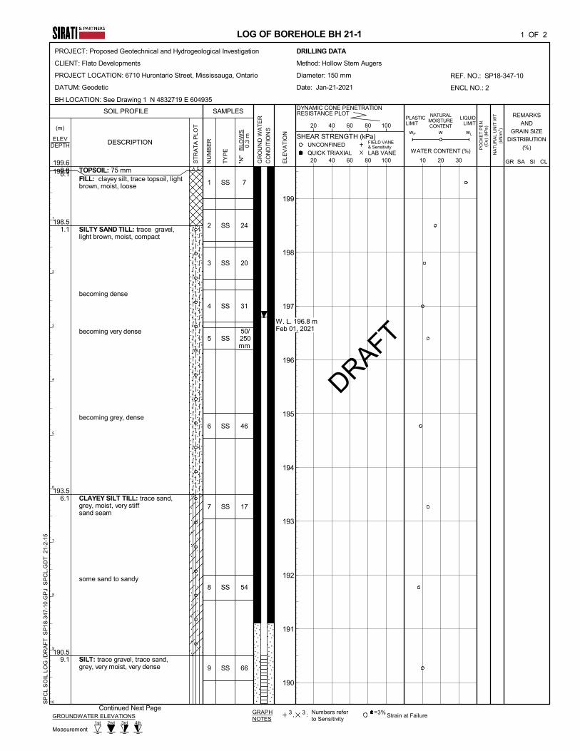
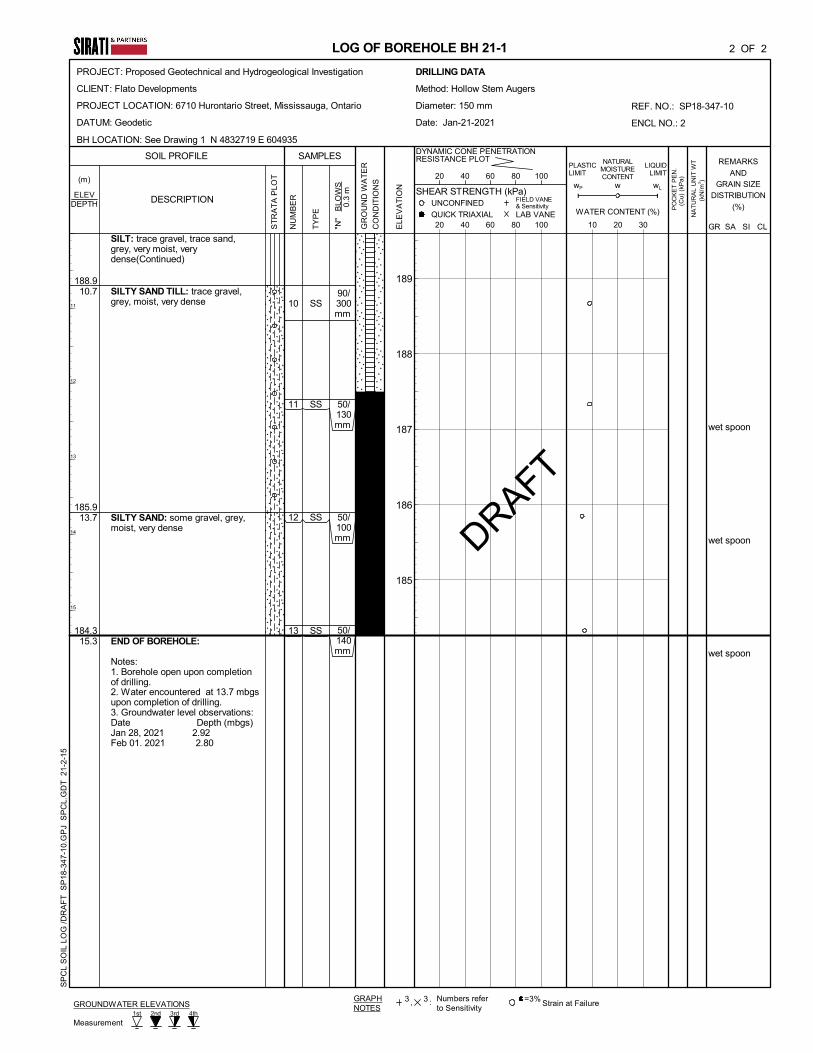
A total of two (3) boreholes (BH21-1 through BH21-3, see Drawing 1 for location plan) were drilled
at the site to the depths ranging between 10.5 m and 15.3 m. Boreholes were drilled with hollow stem
continuous flight auger equipment by a drilling sub-contractor under the direction and supervision of
SIRATI personnel. Samples were retrieved at regular intervals with a 50 mm O.D. split-barrel
sampler driven with a hammer weighing 624 N and dropping 760 mm in accordance with the
Standard Penetration Test (SPT) method.
In additional to the above boreholes, the stratigraphy and groundwater level obtained from boreholes
BH1 through BH3 and BH6 through BH8, drilled by SIRATI during August 2018 (Report No. SP18-
347-10) were used in this report. The location of the boreholes is presented in Figure 1. The borehole
logs are presented in Appendix A.
The field work was carried out in accordance with the ASTM D 1586-11 test method – “The Standard
Method of Standard Penetration Testing (SPT)”. All soil samples were logged in the field and
returned to SIRATI’s laboratory in King City for detailed examination by the project engineer and
subsequent laboratory testing.
As part of the geotechnical investigation in 218, four (4) representative soil samples were subjected to
particle size analysis and hydrometer analysis. The results of the laboratory tests are provided in
respective borehole logs in Appendix A. Additional tests, including particle size analysis, hydrometer
analysis, and Atterberg limits tests were performed on representative soil samples of boreholes BH21-
1 BH21-03. The results of the laboratory tests will be provided in the final report.
Groundwater level observations were made during drilling and in the open boreholes and upon
completion of the drilling operations. Monitoring wells were installed at four (4) borehole locations
(BH2, BH7, BH21-1, and BH21-2) for long-term (stabilized) groundwater level monitoring.

Project: SP18-347-10-R2 Geotechnical Investigation Flato Developments Proposed Commercial Development 6710 Hurontario Street, Mississauga, Ontario
SIRATI & PARTNERS CONSULTANTS LIMITED 3
MARCH 5, 2021
The elevations at the borehole locations were surveyed by SIRATI personnel using differential GPS
system and varied from 199.5 m to 200.2 m.
3. SUBSURFACE CONDITIONS
The borehole locations are shown on Drawing 1. Notes on sample descriptions and the general
features of fill material and glacial till are presented on Drawing 1A. Detailed subsurface conditions
are presented on the Borehole Logs, Drawings 2 to 4, as well as in Appendix A. The soil and
groundwater conditions are summarized as follows.
3.1 SOIL CONDITIONS
Topsoil: A surficial layer of topsoil was encountered at all borehole locations. The thickness of
topsoil was varying between 40 mm and 150 mm.
The thickness of the topsoil in each borehole is presented in the respective borehole logs. It should be
noted that the thickness of the topsoil explored at the borehole locations may not be representative for
the entire site and should not be relied on to calculate the amount of topsoil to be stripped at the site.
Variable Fill: A heterogeneous mixture of fill material was encountered directly below the topsoil
layer in all boreholes. Fill material generally consists of sandy silt/silty sand to clayey silt. Occasional
traces of topsoil and gravel were observed in fill material.
The fill material extends to a depth of 0.8 m to 1.5 mbgs. The measured SPT ‘N’ values in the fill
material ranged from 6 to 23 blows for 300 mm sampler penetration, indicating its loosely to
moderately compacted state. The higher ‘N’ values may be due to the presence of gravel or cobbles
within the fill material.
Cohesionless Soil Layers: Native cohesionless soil layers consisting of silty sand/sandy silt or silt
were encountered directly underlaying the fill material (BH1 and BH8) or sandwiched into the till
deposit (BH7, BH 21-1, and BH21-3).
The SPT ‘N’ values were recorded ranging between 17 (in BH8) and more than 50 blows per 300 mm
penetration (in BH7), indicating a compact to very dense condition of the soil.
BH7 and BH21-1 were terminated in cohesionless soil deposit.
The moisture content in cohesionless soil deposit was found ranging from 6% to 11.4%, indicating a
moist condition.
Sandy Silt/silty sand Till: The native sandy silt/silty sand till deposit was encountered in upper and
lower horizon layers. The upper layer of sandy silt till was encountered directly underlaying the fill
material and cohesionless soil deposit. The lower horizon layer was encountered underneath the
clayey silt till deposit.
All boreholes except BH7, BH21-1, and BH21-3 were terminated in sandy silt/silty sand till deposit.

Project: SP18-347-10-R2 Geotechnical Investigation Flato Developments Proposed Commercial Development 6710 Hurontario Street, Mississauga, Ontario
SIRATI & PARTNERS CONSULTANTS LIMITED 4
MARCH 5, 2021
The SPT ‘N’ values were recorded in sandy silt/ silty sand till deposit ranging from 16 (in BH21-2) to
more than 50 blows per 300 mm penetration (in multiple boreholes), indicating compact to very dense
condition of the soil.
The moisture content in sandy silt till deposit was found ranging 7.2% to 14.3%, indicating moist to
very moist condition.
Grain size analysis of two (2) representative soil samples (BH2/SS8 and BH7/SS4) were conducted
and the results are presented in Figure 5, with the following fractions:
Clay: 14% to 19%
Silt: 43% to 49%
Sand: 33% to 35%
Gravel: 3% to 4%
The result of Atterberg Limits conducted on one (1) representative soil sample (BH7/SS4) is
presented in Figure 6.
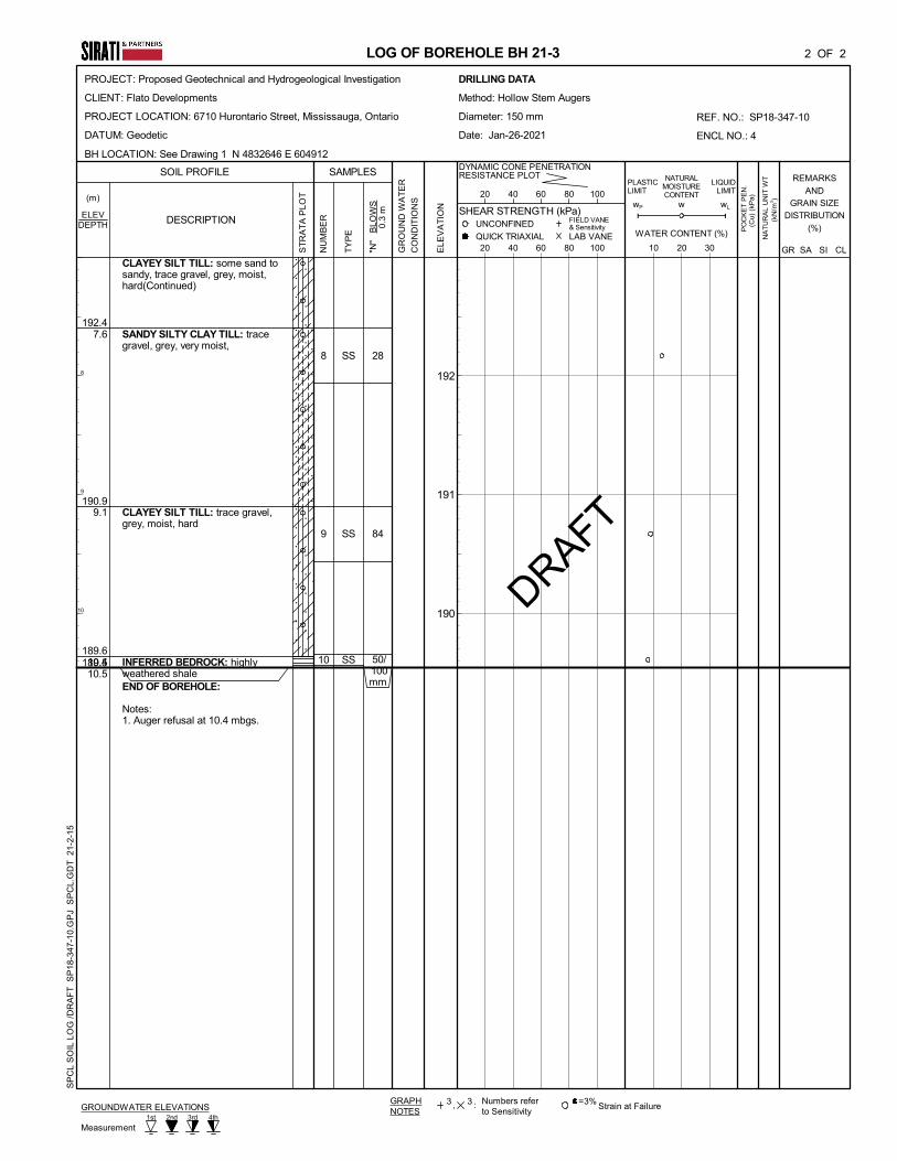
Cohesive Till: Clayey silt to silty clay till deposit was encountered interbedded in sandy silt/silty
sand till deposit in all boreholes except BH21-2. The layer was encountered at 3 m to 6.1 m,
extending to depths of 7.6 m to 10.3 m below the existing grade.
The SPT ‘N’ values were recorded in the cohesive till deposit ranging from 14 (in BH8) to more than
50 blows per 300 mm penetration (in BH1, BH21-1, and BH21-3), indicating very stiff to hard
consistency of the soil.
The moisture content in clayey silt till deposit was found ranging 7.2% to 15.6%, indicating moist to
very moist condition.
Grain size analysis of two (2) representative soil samples (BH1/SS7 and BH6/SS7) were conducted
and the results are presented in Figure 5, with the following fractions:
Clay: 18% to 21%
Silt: 45% to 51%
Sand: 26% to 28%
Gravel: 5% to 6%
The results of Atterberg Limits conducted on two (2) representative soil samples (BH1/SS7 and
BH6/SS7) are presented in Figure 6.
Inferred Weathered Shale: Inferred weathered shale of Georgian Bay Formation was encountered
in BH21-3, at 10.5 m depth, corresponding to geodetic elevation of 189.4 mASL. The inference was

Project: SP18-347-10-R2 Geotechnical Investigation Flato Developments Proposed Commercial Development 6710 Hurontario Street, Mississauga, Ontario
SIRATI & PARTNERS CONSULTANTS LIMITED 5
MARCH 5, 2021
made based on the split spoon sampled recovered from the depth and auger refusal. Similarly, auger
refusal was encountered in BH21-2 at 187.3 mASL. Given that no bedrock was encountered in BH21-
1, advanced to 184.3 mASL, or in BH1, advanced to 184.5 mASL, bedrock elevation is expected to
significantly vary within the site.
3.2 GROUNDWATER CONDITIONS
During drilling (short-term), groundwater was found in the boreholes at approximately 8.9 to 13.7 m
below the existing grade, except for BH21-2 which was in dry condition. The stabilized groundwater
table in the monitoring wells was observed on August 30, 2018 and February 01, 2021 at depths
ranging from 2.5 m to 4.2 mbgs, corresponding to elevations ranging from 196.0 m to 197.1 m
(Geodetic), as listed on Table 1.
Table 1: Groundwater Levels Observed in Monitoring Wells
BH
No.
Date of
Drilling
Date of
Observation
Depth of
Groundwater below
existing ground (m)
Elevation of
Groundwater (m)
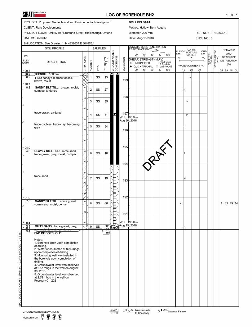
BH2 August 14,
2018
August 14, 2018
August 30, 2018
8.9
2.6
190.6
196.9
BH7 August 16,
2016
August 16, 2018
August 30, 2018
10.2
2.5
189.4
197.1
BH21-1 January 24,
2021
January 28, 2021
February 01, 2021
2.9
2.8
196.7
196.8
BH21-2 January 25,
2021
January 28, 2021
February 01, 2021
4.1
4.2
196.1
196.0
It should be noted that the groundwater levels can vary and are subject to seasonal fluctuations in
response to major weather events.
4. DISCUSSION AND RECOMMENDATIONS
It is understood that the property will be developed with a hotel and service building with three levels
of underground parking. The proposed development will include a seven-story building, a five-story
building, a two-story podium and a one-story banquet hall.
Inferred bedrock of Georgian Bay Formation was encountered in BH21-3 at 189.6 m ASL. The
contractor shall make allowance for excavating through bedrock below a geodetic elevation of 190
mASL.
Glacial till deposits are generally known to contain boulders. As such, the excavation contractor shall
make allowance for it.

Project: SP18-347-10-R2 Geotechnical Investigation Flato Developments Proposed Commercial Development 6710 Hurontario Street, Mississauga, Ontario
SIRATI & PARTNERS CONSULTANTS LIMITED 6
MARCH 5, 2021
4.1 ROADS
The investigation has shown that the predominant subgrade soil at the site, after stripping the topsoil,
fill material and any other organic and otherwise unsuitable material is capable to support the
pavement structure.
Based on the above and assuming that traffic usage will be residential minor local or local, the
following minimum pavement thickness is recommended:
40 mm HL3 Asphaltic Concrete
50 mm HL8 Asphaltic Concrete
150 mm Granular ‘A’
300 mm Granular ‘B’
These values may need to be adjusted according to the City of Mississauga Standards. The pavement
structure recommended above assumes that the subgrade has sufficient bearing capacity to
accommodate the applied pavement structure and local traffic. The site subgrade and weather
conditions (i.e. if wet) at the time of construction may necessitate the placement of thicker granular
sub-base layer in order to facilitate the construction. Furthermore, heavy construction equipment may
have to be kept off the newly prepared road subgrade before the placement of asphalt and/or
immediately thereafter, to avoid damaging the weak subgrade by heavy truck traffic.
4.1.1 Stripping, Sub-excavation and Grading
The site should be stripped of all topsoil, weathered/disturbed soils and any organic or otherwise
unsuitable soils to the full depth of the roads, both in cut and fill areas.
Following stripping, the site should be graded to the subgrade level and approved. The subgrade
should then be proof-rolled, in the presence of the Geotechnical Engineer, by at least several passes of
a heavy compactor having a rated capacity of at least 10 tons. Any soft spots thus exposed should be
removed and replaced by select fill material, similar to the existing subgrade soil and approved by the
Geotechnical Engineer. The subgrade should then be recompacted from the surface to at least 98% of
its Standard Proctor Maximum Dry Density (SPMDD). The final subgrade should be cambered or
otherwise shaped properly to facilitate rapid drainage and to prevent the formation of local
depressions in which water could accumulate.
Proper cambering and allowing the water to escape towards the sides (where it can be removed by
means of subdrains) is considered to be beneficial. Otherwise, any water collected in the granular sub-
base materials could be trapped thus causing problems due to softened subgrade, differential frost
heave, etc. For the same reason damaging the subgrade during and after placement of the granular
materials by heavy construction traffic should be avoided. If the moisture content of the local material
cannot be maintained at ±2% of the optimum moisture content, imported granular material must be
used.

Project: SP18-347-10-R2 Geotechnical Investigation Flato Developments Proposed Commercial Development 6710 Hurontario Street, Mississauga, Ontario
SIRATI & PARTNERS CONSULTANTS LIMITED 7
MARCH 5, 2021
Any fill required for re-grading the site or backfill should be select, clean material, free of topsoil,
organic or other foreign and unsuitable matter. The fill should be placed in thin layers and compacted
to at least 95% of its SPMDD. The degree of compaction should be increased to 98% within the top
1.0 m of the subgrade, as per City Standards. The compaction of the new fill should be checked by
frequent field density tests.
4.1.2 Construction
Once the subgrade has been inspected and approved, the granular base and sub-base course materials
should be placed in layers not exceeding 200 mm (uncompacted thickness) and should be compacted
to at least 100% of their respective SPMDD. The grading of the material should conform to current
OPS Specifications.
The placing, spreading and rolling of the asphalt should be in accordance with OPS Specifications or,
as required by the local authorities.
Frequent field density tests should be carried out on both the asphalt and granular base and sub-base
materials to ensure that the required degree of compaction is achieved.
4.1.3 Drainage
The City of Mississauga requires the installation of full-length subdrains on all roads. The subdrains
should be properly filtered to prevent the loss of (and clogging by) soil fines.
All paved surfaces should be sloped to provide satisfactory drainage towards catch basins. As
discussed in Section 4.1.1, by means of good planning any water trapped in the granular sub-base
materials should be drained rapidly towards subdrains or other interceptors.
4.2 SEWERS
As a part of the site development, a network of new storm and sanitary sewers is to be constructed.
4.2.1 Trenching
It is expected that the trenches will be dug through fill material and native soil deposits. The
groundwater was observed in the monitoring wells at 196.0 mASL to 197.1 mASL. For any trenching
below the groundwater level, water table must be lowered to 1.0 m below the lowest excavation level.
All excavations must be carried out in accordance with the most recent Occupational Health and
Safety Act (OHSA). In accordance with OHSA, fill material can be classified as Type 4 Soil.
Cohesive till deposits can be classified as Type 2 Soil above groundwater table and Type 3 Soil
below groundwater table. Native cohesionless Soils can be classified as Type 3 Soil above
groundwater table and Type 4 Soil below groundwater table.

Project: SP18-347-10-R2 Geotechnical Investigation Flato Developments Proposed Commercial Development 6710 Hurontario Street, Mississauga, Ontario
SIRATI & PARTNERS CONSULTANTS LIMITED 8
MARCH 5, 2021
4.2.2 Bedding
The boreholes show that, in their undisturbed state, native soils will provide adequate support for the
sewer pipes and allow the use of normal Class B type bedding. The recommended minimum
thickness of granular bedding below the invert of the pipes is 150 mm. The thickness of the bedding
may, however, have to be increased depending on the pipe diameter. The bedding material should
consist of well-graded granular material such as Granular ‘A’ or equivalent. After installing the pipe
on the bedding, a granular surround of approved bedding material, which extends at least 300 mm
above the obvert of the pipe, or as set out by the local Authority, should be placed.
To avoid the loss of soil fines from the subgrade, uniformly graded clear stone should not be used
unless, below the granular bedding material, a suitable, approved filter fabric (geotextile) is placed.
The geotextile should extend along the sides of the trench and should be wrapped all around the
poorly graded bedding material.
4.2.3 Backfilling of Trenches
Based on visual and tactile examination, and the measured moisture contents of the soil samples, the
onsite excavated soils from above the groundwater table will generally need to be brought to ±2% of
the optimum moisture content whether by adding water or aerating. Soils excavated from below the
groundwater table may require aeration prior to their use as backfill material.
The backfill should be placed in maximum 200 mm thick layers at or near (±2%) their optimum
moisture content, and each layer should be compacted to at last 95% SPMDD. Unsuitable materials
such as organic soils, boulders, cobbles, frozen soils, etc. should not be used for backfilling.
Otherwise imported selected inorganic fill will be required for backfilling at this site.
The onsite excavated soils should not be used in confined areas (e.g. around catch basins and laterals
under roadways) where heavy compaction equipment cannot be operated. The use of imported
granular fill would be preferable in confined areas and around structures, such as catch basins.
4.3 SITE GRADING AND ENGINEERED FILL
In the areas where earth fill is required for site grading purposes, an engineered fill may be
constructed below building foundations, roads, boulevards, etc.
Prior to the construction of engineered fill, all topsoil, fill material, weak weathered / disturbed and
any other unsuitable materials must be removed in this area. After the removal of all unsuitable
materials, the excavation base consisting of native soil deposits must be inspected and approved by a
qualified geotechnical engineer prior to any placement of engineered fill. The base of the excavation
should be compacted, and proof rolled with heavy compactors (minimum 10,000 kg). During proof
rolling, spongy, wet or soft/loose spots should be sub-excavated to stable subgrade and replaced with
approved soil, compatible with subgrade conditions, as directed by the geotechnical engineer.

Project: SP18-347-10-R2 Geotechnical Investigation Flato Developments Proposed Commercial Development 6710 Hurontario Street, Mississauga, Ontario
SIRATI & PARTNERS CONSULTANTS LIMITED 9
MARCH 5, 2021
The material for engineered fill should consist of approved inorganic soil, compacted to 100 percent
of Standard Proctor Maximum Dry Density (SPMDD). Recommendations regarding engineered fill
placement are provided in Appendix B of this report.
To reduce the risk of improperly placed engineered compacted fill, full-time supervision of the
contractor is essential by SIRATI to certify the engineered fill. Please note that SIRATI can only
provide certification for material properly placed and compacted under direct supervision. Detailed
Engineered fill and inspection requirements to be discussed at the pre-construction meeting with the
contractor.
Depending upon the amount of grade raise, there will be consolidation settlement of the underlying
soils. Additionally, there will be settlement of the engineered fill under its own weight, approximately
0.5% of the fill height. A waiting period of 3 to 6 months may be required prior to the construction of
any structures on engineered fill. This should be confirmed during the detail design stage, once the
grading plans for the proposed development are available.
4.4 FOUNDATION CONDITIONS
According to the latest architectural drawing provided by the Client, P2 Parking level will be at
193.63 m ASL, and P3 Parking level will be at 190.63 m ASL.
4.4.1 Frost Protection
All footings exposed to seasonal freezing conditions must have at least 1.2 meters of soil cover for
frost protection.
4.4.2 Conventional Strip/Spread Footings
Table 2 shows the allowable soil bearing values at serviceability limit state (SLS) and ultimate limit
state (ULS) in the undisturbed inorganic natural soils, at or below the geodetic elevations of 193.2 m
and 190.2 m. The bearing value would be suitable for the use of normal strip or spread footings to
support the proposed development. It should be noted that the bearing capacities were provided based
on the soil and groundwater condition at the borehole locations and as such, variability should be
anticipated between the boreholes.
Table 2: Bearing Values and Founding Elevations for Conventional Footings
BH
No. Founding Material
Bearing
Capacity
at SLS
(kPa)
Factored
Geotechnical
Resistance at
ULS
(kPa)
Minimum
Depth Below
Existing
Ground
(m)
Founding
Level at or
Below
Elevation
(m)
BH1 Clayey Silt Till
Sandy Silt Till 200
500
300
750
6.9
9.9
193.2
190.2

Project: SP18-347-10-R2 Geotechnical Investigation Flato Developments Proposed Commercial Development 6710 Hurontario Street, Mississauga, Ontario
SIRATI & PARTNERS CONSULTANTS LIMITED 10
MARCH 5, 2021
BH2 Clayey Silt Till
Silty Sand
200
500
300
750
6.3
9.3
193.2
190.2
BH3 Clayey Silt Till
Sandy Silt Till
200
500
300
700
7.0
10.0
193.2
190.2
BH6 Clayey Silt Till
Sandy Silt Till
200
500
300
750
6.9
9.9
193.2
190.2
BH7 Clayey Silt Till
Sandy Silt Till
200
500
300
700
6.4
9.4
193.2
190.2
BH8 Clayey Silt Till
Sandy Silt Till to Sand
200
500
300
750
6.5
9.5
193.2
190.2
BH21-1 Clayey Silt Till
Silt
200
500
300
700
6.4
9.4
193.2
190.2
BH21-2 Sandy Silt Till
Sandy Silt Till
200
500
300
750
7.0
10.0
193.2
190.2
BH21-3 Clayey Silt Till
Clayey Silt Till
200
500
300
750
6.8
9.8
193.2
190.2
The foundations designed to the above specified allowable bearing capacity at the serviceability limit
states (SLS) are expected to settle less than 25 mm of total and 19 mm of differential settlements.
Considerations must be given to the adjacent foundation element structures (if supported by different
types of foundations) to minimize loading interaction/influence. If the low-rise building footings will
be supported by the caissons and underground parking structure will be supported by spread/strip
footings, in such conditions, it is prudent to structurally separate the footings from each other.
All footing bases must be inspected by this office prior to pouring concrete. It is suggested that a lean
concrete mat slab be placed immediately after the excavation is complete to avoid weathering of the
soil unless the footings are cast immediately after excavation.
Where construction is undertaking during winter conditions, footing subgrade should be protected
from freezing. Foundation walls and columns should be protected against heave due to soil ad-
freezing.
Positive dewatering will be required prior to the strip and spread foundation construction below the
groundwater table, otherwise it will result in unstable base and loss of bearing capacity. Groundwater
table must be lowered to at least 1m below the lowest founding level prior to excavation.
4.4.3 Caisson Foundation
Alternatively, Shallow caisson foundation may be used for the proposed development. The diameter
of the caissons should be at least 760 mm to allow safe passage for the cleaning and inspection of the
base of each caisson base prior to pouring concrete. The caisson Contractor should be advised to
provide temporary smooth surface liners for sealing off any wet pocket in the fill or wet seams in the
relatively impervious clayey silt, and to allow safe passage for the cleaning and inspection of the
caisson bases.

Project: SP18-347-10-R2 Geotechnical Investigation Flato Developments Proposed Commercial Development 6710 Hurontario Street, Mississauga, Ontario
SIRATI & PARTNERS CONSULTANTS LIMITED 11
MARCH 5, 2021
A net allowable bearing pressure of 700 kPa (SLS) and 1.0 MPa (ULS) may be used for the
embedment into the very dense to hard soil with the approximate elevation of 190.0 m Geodetic. It is
anticipated that the associated settlements are not expected to be large, and in general limiting of the
total settlement to less than 25 mm and the differential settlement to less than 20 mm by the
recommended net bearing pressure is considered appropriate.
Prior to pouring concrete, the base of each caisson should be inspected by the Geotechnical Engineer.
The investigation and comments are necessarily on-going as new information of the underground
conditions becomes available. For example, more specific information is available with respect to
conditions between boreholes when foundation construction is underway. The interpretation between
boreholes and the recommendations of this report must therefore be checked through field inspections
provided by SIRATI to validate the information for use during the construction stage.
5. FLOOR SLAB AND PERMANENT DRAINAGE
Depending upon the lowest underground parking level of the building in relation to the long-term
ground water level, the basement may need to be constructed as a ‘water-tight’ structure or be
continuously managed be an appropriately designed dewatering system. For construction, the
basement excavation may extend 1 or 2 m below the basement level and would carry out with
conventional dewatering from inside. Attention would be required with regard to stability of the base
of the excavation. In addition, the basement substructure would require suitable water proofing
measures to keep it in a dry condition.
In order to facilitate foundation and basement construction, appropriate dewatering measures will be
required by a dewatering contractor.
With three (3) level of basement, the basement floor slab can be supported on grade provided the base
thoroughly proof rolled to detect any soft or unstable areas, which must be removed and replaced with
suitably compacted soils, as defined in Section 4 of this report. Once the required subgrade has been
developed, SIRATI recommends that the exposed subgrade be inspected and approved by the
Geotechnical Engineer prior to the placement of any granular fill or concrete. A granular layer
consisting of at least 200 mm of 19 mm Crusher Run Limestone (CRL) or OPSS Granular A should
be installed under the floor slab as a granular base layer. The Granular material should be compacted
to 100% of its SPMDD.
It is considered by SIRATI that completed excavations for floor slabs should not be left open before
pouring concrete for any period longer than 24 hours. Particularly, if the floor construction works are
being completed during the winter months or wet weather periods. The base of any floor slab
excavation that is left exposed longer than 24 hours should be suitably covered and protected from
water ponding, and/or protected to prevent degradation of the exposed founding stratum with the
construction of a mud mat.
The floor slab should be structurally independent of any load bearing structural elements and should
tolerate expected foundation settlements as indicated above.

Project: SP18-347-10-R2 Geotechnical Investigation Flato Developments Proposed Commercial Development 6710 Hurontario Street, Mississauga, Ontario
SIRATI & PARTNERS CONSULTANTS LIMITED 12
MARCH 5, 2021
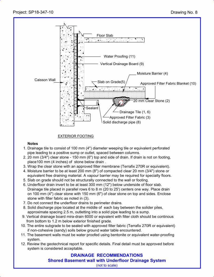
The perimeter drainage system shown on Drawings 11 and 12 are recommended for shored
excavations. Weeping tile systems on the exterior and underfloor drainage systems, should be
appropriately designed to effectively discharge water and eliminate hydrostatic pressure build-ups.
6. EARTH PRESSURES
The lateral earth and water pressure acting at any depth on the basement walls can be calculated by
the following formula:
In soils above the groundwater table (z < dw):
p = K ( z + q)
In soils below the groundwater table (z ≥ dw):
p = K { dw + 1 (z - dw) + q} + pw
In which, pw = w (z - dw)
where p = lateral earth and water pressure in kPa acting at a depth of z below ground surface
K = earth pressure coefficient = 0.47
= unit weight of soil above groundwater table, assuming = 21.5 kN/m3
1 = submerged unit weight of soil below groundwater table, assuming
1 = 11.7 kN/m3
w = unit weight of water, assuming w = 9.8 kN/m3
z = depth below ground surface to point of interest, in meters
dw = depth of groundwater table below ground surface, in meters
q = value of surcharge in kPa
pw = hydrostatic water pressure in kPa
When the basement wall is poured against the shoring caisson wall, the basement wall as well as the
shoring caisson wall should be designed for hydrostatic pressure, even though a drainage board is
provided between the basement wall and the caisson wall. For the design of the basement walls and
shoring caisson wall, the groundwater table elevation at the site can be considered varying between
196.9 and 197.1 mASL.
7. TEMPORARY SHORING
It is understood that the proposed excavations will be supported by a temporary shoring system
consisting of timber lagging and soldier piles. A tightly-braced caisson wall may also be required to
support adjacent structures.

Project: SP18-347-10-R2 Geotechnical Investigation Flato Developments Proposed Commercial Development 6710 Hurontario Street, Mississauga, Ontario
SIRATI & PARTNERS CONSULTANTS LIMITED 13
MARCH 5, 2021
The presence of groundwater table in the cohesionless deposits (sand, silt, sandy silt to silty sand) will
make the construction of the shoring caissons difficult and therefore appropriate protection must be
provided to prevent the soil from caving and thus minimize the possible formation of voids below the
floor slab and adjacent foundations.
The shoring system must be designed in accordance with the Fourth Edition of the Canadian
Foundation Engineering Manual. The soil parameters estimated to be applicable for this design are as
follows:
1) Earth Pressure Coefficients
(a) where movement must be minimal:
K=0.47
(b) where minor movement (.002H) can be tolerated, K=0.31
(c) passive earth pressure for soldier piles (unfactored), Kp=3.25 for the very
dense soils
2) For stability check
= 32
c= 0
= 22 kN/m3
Surcharge is to be determined by shoring contractor.
3) For earth anchors
Bond value of 50 kPa is suggested; this value depends on anchor installation methods
and grouting procedures. Gravity poured concrete can result in low bond values while
pressure grouted anchors will give higher values and produce a more satisfactory
anchor.
Safe net bearing value for soldier pile caissons base assuming clean dry hole is q = 500 kPa.
Assuming a slurry procedure and tremie concrete, then q = 300 kPa
Casing will be required during the construction of the tiebacks to prevent caving of soils. The soldier
piles should be installed in pre-augured holes taken below the deepest excavation. The holes should
be filled with concrete below the excavation level and half bag mix above the base of the excavation.
The concrete strength must be specified by the shoring designer. Temporary liners will be required to
help prevent the sandy and gravelly soils from caving during the installation period. Measures will be
required to prevent the loss of soil through the spaces between the lagging boards (if used). This
could be achieved by installing a geotextile filter cloth behind the lagging boards.

Project: SP18-347-10-R2 Geotechnical Investigation Flato Developments Proposed Commercial Development 6710 Hurontario Street, Mississauga, Ontario
SIRATI & PARTNERS CONSULTANTS LIMITED 14
MARCH 5, 2021
Soil anchors will be required to support the shoring. The anchors must be of a length that meets the
Canadian Foundation Manual recommendations. It is important to note that the minimum length lies
beyond the 45 - /2 + .15H line drawn from the base of the soldier pile and the overall stability of the
system must be checked at each anchor level.
The top anchor must not be placed lower than 3.0 meters below the top of level ground surface.
Anchors will require casing when penetrating through wet sand and silt layers. The suggested bond
value of 50 KPa is arbitrary since the contractor’s installation procedures will determine the actual
soil to concrete bond value. Hence, the contractor must decide on a capacity and confirm its
availability. All anchors must be tested as indicated in the Foundation Manual, 4th edition.
Adhesion on the buried caisson shaft or behind the shoring system must be neglected when designing
this shoring system.
Movement of the shoring system is inevitable. Vertical movements will result from the vertical load
on the soldier piles resulting from the inclined tiebacks and inward horizontal movement results from
earth and water pressures. The magnitude of this movement can be controlled by sound construction
practices, and it is anticipated that the horizontal movement will be in the range of 0.1 to 0.25%H.
To ensure that movements of the shoring are within an acceptable range, monitoring must be carried
out. Vertical and horizontal targets on the soldier piles must be located and surveyed before
excavation begins. Weekly readings during excavation should show that the movements will be
within those predicted; if not, the monitoring results will enable directions to be given to improve the
shoring.
8. EARTHQUAKE CONSIDERATIONS
Based on the borehole information and according to Table 4.1.8.4.A of OBC 2012, the subject site for
the proposed building founded on dense to very dense soils can be classified as “Class C”.
9. GENERAL COMMENTS ON REPORT
Sirati & Partners Consultants Limited should be retained for a general review of the final design and
specifications to verify that this report has been properly interpreted and implemented. If not accorded
the privilege of making this review, Sirati & Partners will assume no responsibility for interpretation
of the recommendations in the report.
The comments given in this report are intended only for the guidance of design engineers. The
number of boreholes required to determine the localized underground conditions between boreholes
affecting construction costs, techniques, sequencing, equipment, scheduling, etc., would be much
greater than has been carried out for design purposes. Contractors bidding on or undertaking the
works should, in this light, decide on their own investigations, as well as their own interpretations of
the factual borehole results, so that they may draw their own conclusions as to how the subsurface
conditions may affect them.


Project: SP18-347-10-R2 Geotechnical Investigation Flato Developments Proposed Commercial Development 6710 Hurontario Street, Mississauga, Ontario
SIRATI & PARTNERS CONSULTANTS LIMITED 1
MARCH 5, 2021
Drawings

BH8MW
7
BH6
BH3
BH21-2
BH21-1
BH21-3
MW2
BH1
Legend:
Project Title:
North:
Site Location:
Figure Title:
Scale: Project Number:
Figure Number:Date:
N
0m 5m 10m
February 2021
Borehole Location Plan
1
6710 Hurontario, Mississauga, ON
Geotechnical and Environmental Investigation
Property Boundary
SP18-347-10
12700- Keele Street King City, ON. L7B 1H5
Phone# 905 833 1582, Fax# 905 833 5360
Borehole
Monitoring Well
Monitoring Well (2021)
Borehole (2021)

Project: SP18-347-10-R2 Geotechnical Investigation Flato Developments Proposed Commercial Development 6710 Hurontario Street, Mississauga, Ontario
SIRATI & PARTNERS CONSULTANTS LIMITED 2
MARCH 5, 2021
Drawing 1A: Notes on Sample Descriptions
1. All sample descriptions included in this report follow the Canadian Foundations Engineering Manual soil classification
system. This system follows the standard proposed by the International Society for Soil Mechanics and Foundation
Engineering. Laboratory grain size analyses provided by Sirati & Partners Consultants Limited also follow the same
system. Different classification systems may be used by others; one such system is the Unified Soil Classification.
Please note that, with the exception of those samples where a grain size analysis has been made, all samples are
classified visually. Visual classification is not sufficiently accurate to provide exact grain sizing or precise
differentiation between size classification systems.
ISSMFE SOIL CLASSIFICATION
CLAY SILT SAND GRAVEL COBBLES BOULDERS
FINE MEDIUM COARSE FINE MEDIUM COARSE FINE MEDIUM COARS
E
0.002 0.006 0.02 0.06 0.2 0.6 2.0 6.0 20 60 200
EQUIVALENT GRAIN DIAMETER IN MILLIMETRES
CLAY (PLASTIC) TO FINE MEDIUM CRS. FINE COARSE
SILT (NONPLASTIC) SAND GRAVEL
UNIFIED SOIL CLASSIFICATION
2. Fill: Where fill is designated on the borehole log it is defined as indicated by the sample recovered during the boring
process. The reader is cautioned that fills are heterogeneous in nature and variable in density or degree of compaction.
The borehole description may therefore not be applicable as a general description of site fill materials. All fills should
be expected to contain obstruction such as wood, large concrete pieces or subsurface basements, floors, tanks, etc., none
of these may have been encountered in the boreholes. Since boreholes cannot accurately define the contents of the fill,
test pits are recommended to provide supplementary information. Despite the use of test pits, the heterogeneous nature
of fill will leave some ambiguity as to the exact composition of the fill. Most fills contain pockets, seams, or layers of
organically contaminated soil. This organic material can result in the generation of methane gas and/or significant
ongoing and future settlements. Fill at this site may have been monitored for the presence of methane gas and, if so, the
results are given on the borehole logs. The monitoring process does not indicate the volume of gas that can be
potentially generated nor does it pinpoint the source of the gas. These readings are to advise of the presence of gas only,
and a detailed study is recommended for sites where any explosive gas/methane is detected. Some fill material may be
contaminated by toxic/hazardous waste that renders it unacceptable for deposition in any but designated land fill sites;
unless specifically stated the fill on this site has not been tested for contaminants that may be considered toxic or
hazardous. This testing and a potential hazard study can be undertaken if requested. In most residential/commercial
areas undergoing reconstruction, buried oil tanks are common and are generally not detected in a conventional
geotechnical site investigation.
3. Till: The term till on the borehole logs indicates that the material originates from a geological process associated with
glaciation. Because of this geological process the till must be considered heterogeneous in composition and as such may
contain pockets and/or seams of material such as sand, gravel, silt or clay. Till often contains cobbles (60 to 200 mm) or
boulders (over 200 mm). Contractors may therefore encounter cobbles and boulders during excavation, even if they are
not indicated by the borings. It should be appreciated that normal sampling equipment cannot differentiate the size or
type of any obstruction. Because of the horizontal and vertical variability of till, the sample description may be
applicable to a very limited zone; caution is therefore essential when dealing with sensitive excavations or dewatering
programs in till materials.
7
24
20
31
50/ 250mm
46
17
54
66
199.5
198.5
193.5
190.5
0.1
1.1
6.1
9.1
SS
SS
SS
SS
SS
SS
SS
SS
SS
1
2
3
4
5
6
7
8
9
TOPSOIL: 75 mmFILL: clayey silt, trace topsoil, lightbrown, moist, loose
SILTY SAND TILL: trace gravel,light brown, moist, compact
becoming dense
becoming very dense
becoming grey, dense
CLAYEY SILT TILL: trace sand,grey, moist, very stiffsand seam
some sand to sandy
SILT: trace gravel, trace sand,grey, very moist, very dense
w
ELE
VA
TIO
N
:
10 20 30
REMARKS
AND
GRAIN SIZE
DISTRIBUTION
(%)
NATURALMOISTURECONTENT
3
SI
GRAPHNOTES
LIQUIDLIMIT
SAMPLES
NU
MB
ER
199
198
197
196
195
194
193
192
191
190
NA
TU
RA
L U
NIT
WT
PO
CK
ET
PE
N.
199.6
PLASTICLIMIT
FIELD VANE& Sensitivity
ELEV
SOIL PROFILE
wL
0.0
UNCONFINED
Continued Next Page
1 OF 2
20 40 60 80 100GR
OU
ND
WA
TE
R
CO
ND
ITIO
NS
"N"
B
LOW
S
0.3
m
DESCRIPTION
PROJECT: Proposed Geotechnical and Hydrogeological Investigation
CLIENT: Flato Developments
PROJECT LOCATION: 6710 Hurontario Street, Mississauga, Ontario
DATUM: Geodetic
BH LOCATION: See Drawing 1 N 4832719 E 604935
GR
REF. NO.: SP18-347-10
ENCL NO.: 2
1
2
3
4
5
6
7
8
9
10
Numbers referto Sensitivity
DYNAMIC CONE PENETRATIONRESISTANCE PLOT
20 40 60 80 100
QUICK TRIAXIAL
SHEAR STRENGTH (kPa)
TY
PE
,3
CL
=3%Strain at Failure
Measurement
(Cu)
(kP
a)(m)
ST
RA
TA
PLO
T
LAB VANE WATER CONTENT (%)
wP
DEPTH
SA
LOG OF BOREHOLE BH 21-1
1st 2nd 4th3rdGROUNDWATER ELEVATIONS
(kN
/m3)
DRILLING DATA
Method: Hollow Stem Augers
Diameter: 150 mm
Date: Jan-21-2021
DRAFT
SP
CL
SO
IL L
OG
/DR
AF
T S
P18
-347
-10.
GP
J S
PC
L.G
DT
21-
2-15
W. L. 196.8 mFeb 01, 2021
90/ 300mm
50/ 130mm
50/ 100mm
50/ 140mm
188.9
185.9
184.3
10.7
13.7
15.3
SS
SS
SS
SS
10
11
12
13
wet spoon
wet spoon
wet spoon
SILT: trace gravel, trace sand,grey, very moist, verydense(Continued)
SILTY SAND TILL: trace gravel,grey, moist, very dense
END OF BOREHOLE:
Notes:1. Borehole open upon completionof drilling.2. Water encountered at 13.7 mbgsupon completion of drilling.3. Groundwater level observations:Date Depth (mbgs)Jan 28, 2021 2.92Feb 01. 2021 2.80
w
ELE
VA
TIO
N
:
302010
REMARKS
AND
GRAIN SIZE
DISTRIBUTION
(%)
NATURALMOISTURECONTENT
3
SI
GRAPHNOTES
LIQUIDLIMIT
SAMPLES
NU
MB
ER
189
188
187
186
185
NA
TU
RA
L U
NIT
WT
PO
CK
ET
PE
N.PLASTIC
LIMIT
FIELD VANE& Sensitivity
ELEV
SOIL PROFILE
wL
UNCONFINED
2 OF 2
80 10020 40 60GR
OU
ND
WA
TE
R
CO
ND
ITIO
NS
"N"
B
LOW
S
0.3
m
DESCRIPTION
PROJECT: Proposed Geotechnical and Hydrogeological Investigation
CLIENT: Flato Developments
PROJECT LOCATION: 6710 Hurontario Street, Mississauga, Ontario
DATUM: Geodetic
BH LOCATION: See Drawing 1 N 4832719 E 604935
GR
REF. NO.: SP18-347-10
ENCL NO.: 2
11
12
13
14
15
Numbers referto Sensitivity
DYNAMIC CONE PENETRATIONRESISTANCE PLOT
20 40 60 80 100
QUICK TRIAXIAL
SHEAR STRENGTH (kPa)
TY
PE
,3
CL
=3%Strain at Failure
Measurement
(Cu)
(kP
a)(m)
ST
RA
TA
PLO
T
LAB VANE WATER CONTENT (%)
wP
DEPTH
SA
LOG OF BOREHOLE BH 21-1
4th3rd2nd1stGROUNDWATER ELEVATIONS
(kN
/m3)
DRILLING DATA
Method: Hollow Stem Augers
Diameter: 150 mm
Date: Jan-21-2021
DRAFT
SP
CL
SO
IL L
OG
/DR
AF
T S
P18
-347
-10.
GP
J S
PC
L.G
DT
21-
2-15
moist, very denseSILTY SAND: some gravel, grey,

7
22
31
24
59
16
16
17
82
200.2
199.4
198.7
195.6
0.0
0.8
1.5
4.6
SS
SS
SS
SS
SS
SS
SS
SS
SS
1
2
3
4
5
6
7
8
9
TOPSOIL: 40 mm FILL: clayey silt with topsoilinclusion, trace rootlets, dark borwn,moist, loose to compact
SANDY SILT TILL: trace cobbles,trace gravel, trace clay, light brown,very moist, compact
SANDY SILT TO SILTY SANDTILL: trace gravel, trace clay, lightbrown, moist, dense
with oxidation, becoming compact
trace cobbles, grey, very dense
SANDY SILT TILL: some cobbles,trace gravel, trace clay, brown togrey, moist, compact
trace cobbles, trace gravel, traceclay, grey, moist
some clay to clayey, trace gravel,grey, moist
- trace to some clay, trace gravel
w
ELE
VA
TIO
N
:
10 20 30
REMARKS
AND
GRAIN SIZE
DISTRIBUTION
(%)
NATURALMOISTURECONTENT
3
SI
GRAPHNOTES
LIQUIDLIMIT
SAMPLES
NU
MB
ER
200
199
198
197
196
195
194
193
192
191
NA
TU
RA
L U
NIT
WT
PO
CK
ET
PE
N.
200.2
PLASTICLIMIT
FIELD VANE& Sensitivity
ELEV
SOIL PROFILE
wL
0.0
UNCONFINED
Continued Next Page
1 OF 2
20 40 60 80 100GR
OU
ND
WA
TE
R
CO
ND
ITIO
NS
"N"
B
LOW
S
0.3
m
DESCRIPTION
PROJECT: Proposed Geotechnical and Hydrogeological Investigation
CLIENT: Flato Developments
PROJECT LOCATION: 6710 Hurontario Street, Mississauga, Ontario
DATUM: Geodetic
BH LOCATION: See Drawing 1 N 4832682 E 604918
GR
REF. NO.: SP18-347-10
ENCL NO.: 3
1
2
3
4
5
6
7
8
9
10
Numbers referto Sensitivity
DYNAMIC CONE PENETRATIONRESISTANCE PLOT
20 40 60 80 100
QUICK TRIAXIAL
SHEAR STRENGTH (kPa)
TY
PE
,3
CL
=3%Strain at Failure
Measurement
(Cu)
(kP
a)(m)
ST
RA
TA
PLO
T
LAB VANE WATER CONTENT (%)
wP
DEPTH
SA
LOG OF BOREHOLE BH 21-2
1st 2nd 4th3rdGROUNDWATER ELEVATIONS
(kN
/m3)
DRILLING DATA
Method: Hollow Stem Augers
Diameter: 150 mm
Date: Jan-25-2021
DRAFT
SP
CL
SO
IL L
OG
/DR
AF
T S
P18
-347
-10.
GP
J S
PC
L.G
DT
21-
2-15
W. L. 196.0 mFeb 01, 2021

96/ 280mm
50/ 130mm
187.313.0
SS
SS
10
11
SANDY SILT TILL: some cobbles,trace gravel, trace clay, brown togrey, moist, compact(Continued)
trace cobbles
END OF BOREHOLE:
Notes:1. Auger refusal at 12.95 mbgs.2. Borehole open and dry uponcompletion of drilling.3. Monitoring well was installed inthe borehole upon completion ofdrilling.4. Monitoring well was covered withstivk up well protective cover.5. Groundwater level observations:Date Depth (mbgs)Jan 28, 2021 4.12Feb 01. 2021 4.19
w
ELE
VA
TIO
N
:
10 20 30
REMARKS
AND
GRAIN SIZE
DISTRIBUTION
(%)
NATURALMOISTURECONTENT
3
SI
GRAPHNOTES
LIQUIDLIMIT
SAMPLES
NU
MB
ER
190
189
188
NA
TU
RA
L U
NIT
WT
PO
CK
ET
PE
N.PLASTIC
LIMIT
FIELD VANE& Sensitivity
ELEV
SOIL PROFILE
wL
UNCONFINED
2 OF 2
20 40 60 80 100GR
OU
ND
WA
TE
R
CO
ND
ITIO
NS
"N"
B
LOW
S
0.3
m
DESCRIPTION
PROJECT: Proposed Geotechnical and Hydrogeological Investigation
CLIENT: Flato Developments
PROJECT LOCATION: 6710 Hurontario Street, Mississauga, Ontario
DATUM: Geodetic
BH LOCATION: See Drawing 1 N 4832682 E 604918
GR
REF. NO.: SP18-347-10
ENCL NO.: 3
11
12
Numbers referto Sensitivity
DYNAMIC CONE PENETRATIONRESISTANCE PLOT
20 40 60 80 100
QUICK TRIAXIAL
SHEAR STRENGTH (kPa)
TY
PE
,3
CL
=3%Strain at Failure
Measurement
(Cu)
(kP
a)(m)
ST
RA
TA
PLO
T
LAB VANE WATER CONTENT (%)
wP
DEPTH
SA
LOG OF BOREHOLE BH 21-2
1st 2nd 4th3rdGROUNDWATER ELEVATIONS
(kN
/m3)
DRILLING DATA
Method: Hollow Stem Augers
Diameter: 150 mm
Date: Jan-25-2021
DRAFT
SP
CL
SO
IL L
OG
/DR
AF
T S
P18
-347
-10.
GP
J S
PC
L.G
DT
21-
2-15

6
19
34
44
52
31
23
199.9
199.2
197.7
197.0
195.4
0.2
0.8
2.3
3.0
4.6
SS
SS
SS
GRAB
SS
SS
SS
1
2
3
4
5
6
7
TOPSOIL: 150 mm
FILL: clayey silt with topsoil to silt,some sand, trace gravel, lightbrown, moist, loose
SANDY SILT TILL: trace gravel,trace clay, light brown, moist,compact to dense
trace cobbles, brown with oxidation
SILTY SAND: trace gravel, traceclay, brown, moist, dense
SANDY SILT TILL: trace gravel,trace rock fragments, brown, moist,very dense
CLAYEY SILT TILL: some sand tosandy, trace gravel, grey, moist,hard
trace cobbles, very moist, very stiff
w
ELE
VA
TIO
N
:
10 20 30
REMARKS
AND
GRAIN SIZE
DISTRIBUTION
(%)
NATURALMOISTURECONTENT
3
SI
GRAPHNOTES
LIQUIDLIMIT
SAMPLES
NU
MB
ER
199
198
197
196
195
194
NA
TU
RA
L U
NIT
WT
PO
CK
ET
PE
N.
200.0
PLASTICLIMIT
FIELD VANE& Sensitivity
ELEV
SOIL PROFILE
wL
0.0
UNCONFINED
Continued Next Page
1 OF 2
20 40 60 80 100GR
OU
ND
WA
TE
R
CO
ND
ITIO
NS
"N"
B
LOW
S
0.3
m
DESCRIPTION
PROJECT: Proposed Geotechnical and Hydrogeological Investigation
CLIENT: Flato Developments
PROJECT LOCATION: 6710 Hurontario Street, Mississauga, Ontario
DATUM: Geodetic
BH LOCATION: See Drawing 1 N 4832646 E 604912
GR
REF. NO.: SP18-347-10
ENCL NO.: 4
1
2
3
4
5
6
7
Numbers referto Sensitivity
DYNAMIC CONE PENETRATIONRESISTANCE PLOT
20 40 60 80 100
QUICK TRIAXIAL
SHEAR STRENGTH (kPa)
TY
PE
,3
CL
=3%Strain at Failure
Measurement
(Cu)
(kP
a)(m)
ST
RA
TA
PLO
T
LAB VANE WATER CONTENT (%)
wP
DEPTH
SA
LOG OF BOREHOLE BH 21-3
1st 2nd 4th3rdGROUNDWATER ELEVATIONS
(kN
/m3)
DRILLING DATA
Method: Hollow Stem Augers
Diameter: 150 mm
Date: Jan-26-2021
DRAFT
SP
CL
SO
IL L
OG
/DR
AF
T S
P18
-347
-10.
GP
J S
PC
L.G
DT
21-
2-15
28
84
50/ 100mm
192.4
190.9
189.6189.5
7.6
9.1
10.410.5
SS
SS
SS
8
9
10
CLAYEY SILT TILL: some sand tosandy, trace gravel, grey, moist,hard(Continued)
SANDY SILTY CLAY TILL: tracegravel, grey, very moist,
CLAYEY SILT TILL: trace gravel,grey, moist, hard
INFERRED BEDROCK: highlyweathered shaleEND OF BOREHOLE:
Notes:1. Auger refusal at 10.4 mbgs.
w
ELE
VA
TIO
N
:
10 20 30
REMARKS
AND
GRAIN SIZE
DISTRIBUTION
(%)
NATURALMOISTURECONTENT
3
SI
GRAPHNOTES
LIQUIDLIMIT
SAMPLES
NU
MB
ER
192
191
190
NA
TU
RA
L U
NIT
WT
PO
CK
ET
PE
N.PLASTIC
LIMIT
FIELD VANE& Sensitivity
ELEV
SOIL PROFILE
wL
UNCONFINED
2 OF 2
20 40 60 80 100GR
OU
ND
WA
TE
R
CO
ND
ITIO
NS
"N"
B
LOW
S
0.3
m
DESCRIPTION
PROJECT: Proposed Geotechnical and Hydrogeological Investigation
CLIENT: Flato Developments
PROJECT LOCATION: 6710 Hurontario Street, Mississauga, Ontario
DATUM: Geodetic
BH LOCATION: See Drawing 1 N 4832646 E 604912
GR
REF. NO.: SP18-347-10
ENCL NO.: 4
8
9
10
Numbers referto Sensitivity
DYNAMIC CONE PENETRATIONRESISTANCE PLOT
20 40 60 80 100
QUICK TRIAXIAL
SHEAR STRENGTH (kPa)
TY
PE
,3
CL
=3%Strain at Failure
Measurement
(Cu)
(kP
a)(m)
ST
RA
TA
PLO
T
LAB VANE WATER CONTENT (%)
wP
DEPTH
SA
LOG OF BOREHOLE BH 21-3
1st 2nd 4th3rdGROUNDWATER ELEVATIONS
(kN
/m3)
DRILLING DATA
Method: Hollow Stem Augers
Diameter: 150 mm
Date: Jan-26-2021
DRAFT
SP
CL
SO
IL L
OG
/DR
AF
T S
P18
-347
-10.
GP
J S
PC
L.G
DT
21-
2-15

0
10
20
30
40
50
60
70
80
90
100
0.001 0.01 0.1 1 10 100
PE
RC
EN
T P
AS
SIN
G
GRAIN SIZE ( mm )
7S-SH1B21018S0
S8-SBH221118S0
S4-SBH721218S0
7S-SH6B21318S0
GRAIN SIZE DISTRIBUTION
CLAY AND SILTSAND GRAVEL
Fine CoarseFine Medium Coarse
1 51"3/41/2#4#16#200 #50#100
GRAIN SIZE IN MICROMETERS
10 30 75503SIEVE DESIGNATION ( Imperial )
3/8"
UNIFIED SOIL CLASSIFICATION SYSTEM
3"
Project: SP18-347-10
Date: September, 2018
Fig: 5

Project No.:
Fig. No. :
Date :
SP18-347-10
September, 2018
Atterberg's Limits TestASTM D4318-10
0
10
20
30
40
50
60
0 10 20 30 40 50 60 70 80 90 100
Pla
stic
ity
In
dex
(P
I)
Liquid Limit (LL or WL)
18S0210 BH1-SS7
18S0212 BH7-SS4
18S0213 BH6-SS7
CL or OL
CH or OH
MH or OH
ML or OL
A LineU Line
CL-ML
6

DRAINAGE RECOMMENDATIONSShored Basement wall with Underfloor Drainage System
(not to scale)
Project: SP18-347-10 Drawing No.7
Notes 1. Drainage tile to consist of 100 mm (4") diameter weeping tile or equivalent perforated pipe leading to a positive sump or outlet, spaced between columns. 2. 20 mm (3/4") clear stone - 150 mm (6") top and side of drain. If drain is not on footing, place100 mm (4 inches) of stone below drain . 3. Wrap the clear stone with an approved filter membrane (Terrafix 270R or equivalent). 4. Moisture barrier to be at least 200 mm (8") of compacted clear 20 mm (3/4") stone or equivalent free draining material. A vapour barrier may be required for specialty floors. 5. Slab on grade should not be structurally connected to the wall or footing. 6. Underfloor drain invert to be at least 300 mm (12") below underside of floor slab. Drainage tile placed in parallel rows 6 to 8 m (20 to 25') centers one way. Place drain on 100 mm (4") clear stone with 150 mm (6") of clear stone on top and sides. Enclose stone with filter fabric as noted in (3). 7. Do not connect the underfloor drains to perimeter drains. 8. Solid discharge pipe located at the middle of each bay between the solider piles, approximate spacing 2.5 m, outletting into a solid pipe leading to a sump. 9. Vertical drainage board with filter cloth should be kept a minium of 1.2 m below exterior finished grade. 10. The entire subgrade to be sealed with approved filter fabric (Terrafix 270R or equivalent) if non-cohesive (sandy) soils below ground water table encountered. 11. The basement walls should be water proofed using bentonite or equivalent water-proofing system.12. Review the geotechnical report for specific details. Final detail must be approved before system is considered acceptable.
EXTERIOR FOOTING
Fabric Filter (9)
Floor Slab
Slab on Grade(5)
Moisture Barrier (4)
20 mm Clear Stone (2)
Drainage Tile (1, 6)
Approved Filter Fabric (3)Solid discharge pipe (8)
Fabric Flap
Shoring
Vertical Drainage Board (9)
Sealant
Approved Filter Fabric Blanket (10)
Water Proofing (11)
DRAINAGE RECOMMENDATIONSShored Basement wall with Underfloor Drainage System
(not to scale)
Project: SP18-347-10 Drawing No. 8
Notes 1. Drainage tile to consist of 100 mm (4") diameter weeping tile or equivalent perforated pipe leading to a positive sump or outlet, spaced between columns. 2. 20 mm (3/4") clear stone - 150 mm (6") top and side of drain. If drain is not on footing, place100 mm (4 inches) of stone below drain . 3. Wrap the clear stone with an approved filter membrane (Terrafix 270R or equivalent). 4. Moisture barrier to be at least 200 mm (8") of compacted clear 20 mm (3/4") stone or equivalent free draining material. A vapour barrier may be required for specialty floors. 5. Slab on grade should not be structurally connected to the wall or footing. 6. Underfloor drain invert to be at least 300 mm (12") below underside of floor slab. Drainage tile placed in parallel rows 6 to 8 m (20 to 25') centers one way. Place drain on 100 mm (4") clear stone with 150 mm (6") of clear stone on top and sides. Enclose stone with filter fabric as noted in (3). 7. Do not connect the underfloor drains to perimeter drains. 8. Solid discharge pipe located at the middle of each bay between the solider piles, approximate spacing 2.5 m, outletting into a solid pipe leading to a sump. 9. Vertical drainage board mira-drain 6000 or eqivalent with filter cloth should be continous from bottom to 1.2 m below exterior finished grade. 10. The entire subgrade to be sealed with approved filter fabric (Terrafix 270R or equivalent) if non-cohesive (sandy) soils below ground water table encountered. 11. The basement walls must be water proofed using bentonite or equivalent water-proofing system.12. Review the geotechnical report for specific details. Final detail must be approved before system is considered acceptable.
EXTERIOR FOOTING
Floor Slab
Slab on Grade(5)
Moisture Barrier (4)
20 mm Clear Stone (2)
Drainage Tile (1, 6)
Approved Filter Fabric (3)Solid discharge pipe (8)
Water Proofing (11)
Caisson Wall
Vertical Drainage Board (9)
Sealant
Approved Filter Fabric Blanket (10)

Project: SP18-347-10-R2 Geotechnical Investigation Flato Developments Proposed Commercial Development 6710 Hurontario Street, Mississauga, Ontario
SIRATI & PARTNERS CONSULTANTS LIMITED 3
MARCH 5, 2021
APPENDIX A:
BOREHOLE LOGS OF 2018 INVESTIGATION

11
23
22
34
33
16
15
17
75/ 250mm
85/275mm
93/ 275mm
69
18
200.0
199.3
198.6
197.8
197.1
195.5
191.0
189.4
187.9
5
0.2
0.8
1.5
2.3
3.0
4.6
9.1
10.7
12.2
SS
SS
SS
SS
SS
SS
SS
SS
SS
SS
SS
SS
1
4
2
3
5
6
7
8
9
10
11
12
26
wet spoon
51
TOPSOIL: 150 mmFILL: sandy silt, mixed withtopsoil, moist
FILL: sandy silt, trace gravel, tracetopsoil, brown, moist
SILTY SAND: trace gravel,brown, moist, compact
SANDY SILT: moist, dense
SANDY SILT TILL: trace gravel,oxidated, brown, moist, dense
CLAYEY SILT TILL: some sand,trace gravel,grey, very moist, verystiff
layer of sandy gravel
SANDY SILT TILL:trace gravel,trace sand, grey, moist, very dense
SANDY SILT TILL:trace gravel,trace sand, grey, wet, very dense
SANDY SILT TILL: trace gravel,trace cobbles, grey, moist, verydense
w
ELE
VA
TIO
N
:
10 20 30
REMARKS
AND
GRAIN SIZE
DISTRIBUTION
(%)
NATURALMOISTURECONTENT
3
SI
GRAPHNOTES
LIQUIDLIMIT
SAMPLES
NU
MB
ER
200
199
198
197
196
195
194
193
192
191
190
189
188
187
NA
TU
RA
L U
NIT
WT
PO
CK
ET
PE
N.
200.1
PLASTICLIMIT
FIELD VANE& Sensitivity
ELEV
SOIL PROFILE
wL
0.0
UNCONFINED
Continued Next Page
1 OF 2
20 40 60 80 100GR
OU
ND
WA
TE
R
CO
ND
ITIO
NS
"N"
B
LOW
S
0.3
m
DESCRIPTION
PROJECT: Proposed Geotechnical and Environmental Investigation
CLIENT: Flato Developments
PROJECT LOCATION: 6710 Hurontario Street, Mississauga, Ontario
DATUM: Geodetic
BH LOCATION: See Drawing 1 N 4832666 E 604855.6
GR
REF. NO.: SP18-347-10
ENCL NO.: 2
1
2
3
4
5
6
7
8
9
10
11
12
13
14
Numbers referto Sensitivity
DYNAMIC CONE PENETRATIONRESISTANCE PLOT
20 40 60 80 100
QUICK TRIAXIAL
SHEAR STRENGTH (kPa)
TY
PE
,3
CL
=3%Strain at Failure
Measurement
(Cu)
(kP
a)(m)
ST
RA
TA
PLO
T
LAB VANE WATER CONTENT (%)
wP
DEPTH
SA
LOG OF BOREHOLE BH1
1st 2nd 4th3rdGROUNDWATER ELEVATIONS
(kN
/m3)
DRILLING DATA
Method: Hollow Stem Augers
Diameter: 200 mm
Date: Aug-14-2018
DRAFT
SP
CL
SO
IL L
OG
/DR
AF
T S
P18
-347
-10.
GP
J S
PC
L.G
DT
21-
2-16
W. L. 186.4 m

88/ 275mm184.5
15.7
SS13
wet spoon
wet spoon
SANDY SILT TILL: trace gravel,trace cobbles, grey, moist, verydense(Continued)
END OF BOREHOLE:
Notes:1. Borehole open upon completionof drilling.2. Water measured at 13.7 mbgsupon completion of drilling.
w
ELE
VA
TIO
N
:
10 20 30
REMARKS
AND
GRAIN SIZE
DISTRIBUTION
(%)
NATURALMOISTURECONTENT
3
SI
GRAPHNOTES
LIQUIDLIMIT
SAMPLES
NU
MB
ER
186
185
NA
TU
RA
L U
NIT
WT
PO
CK
ET
PE
N.PLASTIC
LIMIT
FIELD VANE& Sensitivity
ELEV
SOIL PROFILE
wL
UNCONFINED
2 OF 2
20 40 60 80 100GR
OU
ND
WA
TE
R
CO
ND
ITIO
NS
"N"
B
LOW
S
0.3
m
DESCRIPTION
PROJECT: Proposed Geotechnical and Environmental Investigation
CLIENT: Flato Developments
PROJECT LOCATION: 6710 Hurontario Street, Mississauga, Ontario
DATUM: Geodetic
BH LOCATION: See Drawing 1 N 4832666 E 604855.6
GR
REF. NO.: SP18-347-10
ENCL NO.: 2
15
Numbers referto Sensitivity
DYNAMIC CONE PENETRATIONRESISTANCE PLOT
20 40 60 80 100
QUICK TRIAXIAL
SHEAR STRENGTH (kPa)
TY
PE
,3
CL
=3%Strain at Failure
Measurement
(Cu)
(kP
a)(m)
ST
RA
TA
PLO
T
LAB VANE WATER CONTENT (%)
wP
DEPTH
SA
LOG OF BOREHOLE BH1
1st 2nd 4th3rdGROUNDWATER ELEVATIONS
(kN
/m3)
DRILLING DATA
Method: Hollow Stem Augers
Diameter: 200 mm
Date: Aug-14-2018
DRAFT
SP
CL
SO
IL L
OG
/DR
AF
T S
P18
-347
-10.
GP
J S
PC
L.G
DT
21-
2-16
Aug 15, 2018
13
27
35
31
34
16
19
66
50/ 100mm
14
199.3
198.7
194.9
191.9
190.4
190.1
4
0.2
0.8
4.6
7.6
9.1
9.4
SS
SS
SS
SS
SS
SS
SS
SS
SS
1
2
3
4
5
6
7
8
9
33 49
TOPSOIL: 180mm FILL: sandy silt, trace topsoil,brown, moist
SANDY SILT TILL: brown, moist,compact to dense
trace gravel, oxidated
trace cobbles, trace clay, becominggrey
CLAYEY SILT TILL: some sand,trace gravel, grey, moist, compact
trace sand
SANDY SILT TILL: some gravel,some sand, moist, dense
SILTY SAND : trace gravel, grey,very moist to wet, very denseEND OF BOREHOLE:
Notes:1. Borehole open upon completionof drilling.2. Water encountered at 8.84 mbgsupon completion of drilling.3. Monitoring well was installed inthe borehole upon completion ofdrilling.4. Groundwater level was observedat 2.57 mbgs in the well on August30, 2018.5. Groundwater level was observedat 2.78 mbgs in the well onFebruary 01, 2021.
w
ELE
VA
TIO
N
:
10 20 30
REMARKS
AND
GRAIN SIZE
DISTRIBUTION
(%)
NATURALMOISTURECONTENT
3
SI
GRAPHNOTES
LIQUIDLIMIT
SAMPLES
NU
MB
ER
199
198
197
196
195
194
193
192
191N
AT
UR
AL
UN
IT W
T
PO
CK
ET
PE
N.
199.5
PLASTICLIMIT
FIELD VANE& Sensitivity
ELEV
SOIL PROFILE
wL
0.0
UNCONFINED
1 OF 1
20 40 60 80 100GR
OU
ND
WA
TE
R
CO
ND
ITIO
NS
"N"
B
LOW
S
0.3
m
DESCRIPTION
PROJECT: Proposed Geotechnical and Environmental Investigation
CLIENT: Flato Developments
PROJECT LOCATION: 6710 Hurontario Street, Mississauga, Ontario
DATUM: Geodetic
BH LOCATION: See Drawing 1 N 4832637 E 604876.1
GR
REF. NO.: SP18-347-10
ENCL NO.: 3
1
2
3
4
5
6
7
8
9
Numbers referto Sensitivity
DYNAMIC CONE PENETRATIONRESISTANCE PLOT
20 40 60 80 100
QUICK TRIAXIAL
SHEAR STRENGTH (kPa)
TY
PE
,3
CL
=3%Strain at Failure
Measurement
(Cu)
(kP
a)(m)
ST
RA
TA
PLO
T
LAB VANE WATER CONTENT (%)
wP
DEPTH
SA
LOG OF BOREHOLE BH2
1st 2nd 4th3rdGROUNDWATER ELEVATIONS
(kN
/m3)
DRILLING DATA
Method: Hollow Stem Augers
Diameter: 200 mm
Date: Aug-15-2018
DRAFT
SP
CL
SO
IL L
OG
/DR
AF
T S
P18
-347
-10.
GP
J S
PC
L.G
DT
21-
2-16
W. L. 190.6 mAug 15, 2018
W. L. 196.9 mAug 30, 2018

15
31
26
23
23
16
21
19
71
50/ 125mm
200.0
199.4
197.2
191.1
189.4
0.3
0.8
3.0
9.1
10.8
SS
SS
SS
SS
SS
SS
SS
SS
SS
SS
1
2
3
4
5
6
7
8
9
10
TOPSOIL: 280 mm
FILL: sandy silt mixed with topsoil,trace gravel, trace topsoil,brown,moist SANDY SILT TILL: brown, moist,dense to compact
trace cobbles
oxidated
CLAYEY SILT TILL: trace gravel,trace sand, brown, moist, very stiff
trace cobbles, becoming grey andvery moist
SANDY SILT TILL: trace gravel,grey, moist, very dense
END OF BOREHOLE:
Notes:1. Borehole open upon completionof drilling.2. Water encountered at 10.77mbgs upon completion of drilling.
w
ELE
VA
TIO
N
:
10 20 30
REMARKS
AND
GRAIN SIZE
DISTRIBUTION
(%)
NATURALMOISTURECONTENT
3
SI
GRAPHNOTES
LIQUIDLIMIT
SAMPLES
NU
MB
ER
200
199
198
197
196
195
194
193
192
191
190
NA
TU
RA
L U
NIT
WT
PO
CK
ET
PE
N.
200.2
PLASTICLIMIT
FIELD VANE& Sensitivity
ELEV
SOIL PROFILE
wL
0.0
UNCONFINED
1 OF 1
20 40 60 80 100GR
OU
ND
WA
TE
R
CO
ND
ITIO
NS
"N"
B
LOW
S
0.3
m
DESCRIPTION
PROJECT: Proposed Geotechnical and Environmental Investigation
CLIENT: Flato Developments
PROJECT LOCATION: 6710 Hurontario Street, Mississauga, Ontario
DATUM: Geodetic
BH LOCATION: See Drawing 1 N 4832669 E 604896
GR
REF. NO.: SP18-347-10
ENCL NO.: 4
1
2
3
4
5
6
7
8
9
10
Numbers referto Sensitivity
DYNAMIC CONE PENETRATIONRESISTANCE PLOT
20 40 60 80 100
QUICK TRIAXIAL
SHEAR STRENGTH (kPa)
TY
PE
,3
CL
=3%Strain at Failure
Measurement
(Cu)
(kP
a)(m)
ST
RA
TA
PLO
T
LAB VANE WATER CONTENT (%)
wP
DEPTH
SA
LOG OF BOREHOLE BH3
1st 2nd 4th3rdGROUNDWATER ELEVATIONS
(kN
/m3)
DRILLING DATA
Method: Solid Stem Augers
Diameter: 150 mm
Date: Aug-15-2018
DRAFT
SP
CL
SO
IL L
OG
/DR
AF
T S
P18
-347
-10.
GP
J S
PC
L.G
DT
21-
2-16
W. L. 189.5 mAug 15, 2018

13
18
23
22
30
25
18
14
21
50/ 75mm
55/ 150mm
21
199.9
198.6
196.3
191.0
189.4
189.1
6
0.2
1.5
3.8
9.1
10.7
11.0
SS
SS
SS
SS
SS
SS
SS
SS
SS
SS
SS
1
2
3
4
5
6
7
8
9
10
11
28 45
TOPSOIL: 200 mm FILL: sandy silt, trace topsoil,brown, moist
trace gravel
SANDY SILT TILL: trace cobbles,brown, moist, compact
trace clay, oxidised
CLAYEY SILT TILL: trace gravel,trace sand, grey, very moist, stiff
trace cobbles
SANDY SILT TILL: trace cobbles,trace gravel, grey, moist, very dense
SILTY SAND: trace gravel, traceshale fragments, grey, wet, verydenseEND OF BOREHOLE:
Notes:1. Borehole open upon completionof drilling.2. Water encountered at 10.36mbgs upon completion of drilling.
w
ELE
VA
TIO
N
:
10 20 30
REMARKS
AND
GRAIN SIZE
DISTRIBUTION
(%)
NATURALMOISTURECONTENT
3
SI
GRAPHNOTES
LIQUIDLIMIT
SAMPLES
NU
MB
ER
200
199
198
197
196
195
194
193
192
191
190
NA
TU
RA
L U
NIT
WT
PO
CK
ET
PE
N.
200.1
PLASTICLIMIT
FIELD VANE& Sensitivity
ELEV
SOIL PROFILE
wL
0.0
UNCONFINED
1 OF 1
20 40 60 80 100GR
OU
ND
WA
TE
R
CO
ND
ITIO
NS
"N"
B
LOW
S
0.3
m
DESCRIPTION
PROJECT: Proposed Geotechnical and Environmental Investigation
CLIENT: Flato Developments
PROJECT LOCATION: 6710 Hurontario Street, Mississauga, Ontario
DATUM: Geodetic
BH LOCATION: See Drawing 1 N 4832706 E 604946.3
GR
REF. NO.: SP18-347-10
ENCL NO.: 5
1
2
3
4
5
6
7
8
9
10
Numbers referto Sensitivity
DYNAMIC CONE PENETRATIONRESISTANCE PLOT
20 40 60 80 100
QUICK TRIAXIAL
SHEAR STRENGTH (kPa)
TY
PE
,3
CL
=3%Strain at Failure
Measurement
(Cu)
(kP
a)(m)
ST
RA
TA
PLO
T
LAB VANE WATER CONTENT (%)
wP
DEPTH
SA
LOG OF BOREHOLE BH6
1st 2nd 4th3rdGROUNDWATER ELEVATIONS
(kN
/m3)
DRILLING DATA
Method: Solid Stem Augers
Diameter: 150 mm
Date: Aug-15-2018
DRAFT
SP
CL
SO
IL L
OG
/DR
AF
T S
P18
-347
-10.
GP
J S
PC
L.G
DT
21-
2-16
W. L. 189.7 mAug 15, 2018

9
20
22
25
34
45
25
22
24
65
90
19
199.4
198.8
193.5
190.5
188.9
188.3
3
0.2
0.8
6.1
9.1
10.7
11.3
SS
SS
SS
SS
SS
SS
SS
SS
SS
SS
SS
1
2
3
4
5
6
7
8
9
10
11
35 43
TOPSOIL: 200 mm FILL: sandy silt, trace topsoil,brown, moist
SANDY SILT TILL: trace gravel,trace clay, brown, moist, compact todense
trace cobbles, oxidised
becoming grey
some clay
CLAYEY SILT TILL: trace gravel,trace sand, grey, moist, very stiff
trace cobbles
SANDY SILT TILL: trace cobbles,trace gravel, grey, moist, dense
SANDY SILT TO SILTY SAND:trace gravel, grey, moist, very dense
END OF BOREHOLE:
Notes:1. Borehole Oopen upon completionof drilling.2. Water encountered at 10.21mbgs upon completion of drilling.3. Monitoring well was installed inthe borehole upon completion ofdrilling.4. Groundwater level was observedat 2.55 mbgs in the well on August30, 2018.5. Groundwater level was observed
w
ELE
VA
TIO
N
:
10 20 30
REMARKS
AND
GRAIN SIZE
DISTRIBUTION
(%)
NATURALMOISTURECONTENT
3
SI
GRAPHNOTES
LIQUIDLIMIT
SAMPLES
NU
MB
ER
199
198
197
196
195
194
193
192
191
190
189
NA
TU
RA
L U
NIT
WT
PO
CK
ET
PE
N.
199.6
PLASTICLIMIT
FIELD VANE& Sensitivity
ELEV
SOIL PROFILE
wL
0.0
UNCONFINED
Continued Next Page
1 OF 2
20 40 60 80 100GR
OU
ND
WA
TE
R
CO
ND
ITIO
NS
"N"
B
LOW
S
0.3
m
DESCRIPTION
PROJECT: Proposed Geotechnical and Environmental Investigation
CLIENT: Flato Developments
PROJECT LOCATION: 6710 Hurontario Street, Mississauga, Ontario
DATUM: Geodetic
BH LOCATION: See Drawing 1 N 4832727 E 604953.8
GR
REF. NO.: SP18-347-10
ENCL NO.: 6
1
2
3
4
5
6
7
8
9
10
11
Numbers referto Sensitivity
DYNAMIC CONE PENETRATIONRESISTANCE PLOT
20 40 60 80 100
QUICK TRIAXIAL
SHEAR STRENGTH (kPa)
TY
PE
,3
CL
=3%Strain at Failure
Measurement
(Cu)
(kP
a)(m)
ST
RA
TA
PLO
T
LAB VANE WATER CONTENT (%)
wP
DEPTH
SA
LOG OF BOREHOLE BH7
1st 2nd 4th3rdGROUNDWATER ELEVATIONS
(kN
/m3)
DRILLING DATA
Method: Hollow Stem Augers
Diameter: 200 mm
Date: Aug-16-2018
DRAFT
SP
CL
SO
IL L
OG
/DR
AF
T S
P18
-347
-10.
GP
J S
PC
L.G
DT
21-
2-16
W. L. 189.4 mAug 16, 2018
W. L. 197.1 mAug 30, 2018

at 2.84 mbgs in the well onFebruary 01, 2021.
w
ELE
VA
TIO
N
:
10 20 30
REMARKS
AND
GRAIN SIZE
DISTRIBUTION
(%)
NATURALMOISTURECONTENT
3
SI
GRAPHNOTES
LIQUIDLIMIT
SAMPLES
NU
MB
ER
NA
TU
RA
L U
NIT
WT
PO
CK
ET
PE
N.PLASTIC
LIMIT
FIELD VANE& Sensitivity
ELEV
SOIL PROFILE
wL
UNCONFINED
2 OF 2
20 40 60 80 100GR
OU
ND
WA
TE
R
CO
ND
ITIO
NS
"N"
B
LOW
S
0.3
m
DESCRIPTION
PROJECT: Proposed Geotechnical and Environmental Investigation
CLIENT: Flato Developments
PROJECT LOCATION: 6710 Hurontario Street, Mississauga, Ontario
DATUM: Geodetic
BH LOCATION: See Drawing 1 N 4832727 E 604953.8
GR
REF. NO.: SP18-347-10
ENCL NO.: 6
Numbers referto Sensitivity
DYNAMIC CONE PENETRATIONRESISTANCE PLOT
20 40 60 80 100
QUICK TRIAXIAL
SHEAR STRENGTH (kPa)
TY
PE
,3
CL
=3%Strain at Failure
Measurement
(Cu)
(kP
a)(m)
ST
RA
TA
PLO
T
LAB VANE WATER CONTENT (%)
wP
DEPTH
SA
LOG OF BOREHOLE BH7
1st 2nd 4th3rdGROUNDWATER ELEVATIONS
(kN
/m3)
DRILLING DATA
Method: Hollow Stem Augers
Diameter: 200 mm
Date: Aug-16-2018
DRAFT
SP
CL
SO
IL L
OG
/DR
AF
T S
P18
-347
-10.
GP
J S
PC
L.G
DT
21-
2-16

8
17
18
22
31
42
22
14
36
48
52/ 150mm
199.6
198.9
198.2
195.1
190.6
189.0
188.7
0.1
0.8
1.5
4.6
9.1
10.7
11.0
SS
SS
SS
SS
SS
SS
SS
SS
SS
SS
SS
1
2
3
4
5
6
7
8
9
10
11
TOPSOIL: 100 mm FILL: silty sand, trace topsoil,brown, moist
SANDY SILT: trace clay, brown,moist, compact
SANDY SILT TO SANDY SILTTILL: trace gravel, trace clay,oxidated, brown, moist, compact todense
trace cobbles
becoming grey
CLAYEY SILT TILL: trace gravel,trace sand, grey, moist, very stiff tohard
becoming very moist
SANDY SILT TILL TO SAND: grey, moist to wet, dense
SANDY SILT TILL : grey, moist tovery moist, very denseEND OF BOREHOLE:
Notes:1. Borehole caved at 8.84 mbgs.2. Water encountered at 8.23 mbgsupon completion of drilling.
w
ELE
VA
TIO
N
:
10 20 30
REMARKS
AND
GRAIN SIZE
DISTRIBUTION
(%)
NATURALMOISTURECONTENT
3
SI
GRAPHNOTES
LIQUIDLIMIT
SAMPLES
NU
MB
ER
199
198
197
196
195
194
193
192
191
190
189
NA
TU
RA
L U
NIT
WT
PO
CK
ET
PE
N.
199.7
PLASTICLIMIT
FIELD VANE& Sensitivity
ELEV
SOIL PROFILE
wL
0.0
UNCONFINED
1 OF 1
20 40 60 80 100GR
OU
ND
WA
TE
R
CO
ND
ITIO
NS
"N"
B
LOW
S
0.3
m
DESCRIPTION
PROJECT: Proposed Geotechnical and Environmental Investigation
CLIENT: Flato Developments
PROJECT LOCATION: 6710 Hurontario Street, Mississauga, Ontario
DATUM: Geodetic
BH LOCATION: See Drawing 1 N 4832713 E 604967.7
GR
REF. NO.: SP18-347-10
ENCL NO.: 7
1
2
3
4
5
6
7
8
9
10
Numbers referto Sensitivity
DYNAMIC CONE PENETRATIONRESISTANCE PLOT
20 40 60 80 100
QUICK TRIAXIAL
SHEAR STRENGTH (kPa)
TY
PE
,3
CL
=3%Strain at Failure
Measurement
(Cu)
(kP
a)(m)
ST
RA
TA
PLO
T
LAB VANE WATER CONTENT (%)
wP
DEPTH
SA
LOG OF BOREHOLE BH8
1st 2nd 4th3rdGROUNDWATER ELEVATIONS
(kN
/m3)
DRILLING DATA
Method: Solid Stem Augers
Diameter: 150 mm
Date: Aug-16-2018
DRAFT
SP
CL
SO
IL L
OG
/DR
AF
T S
P18
-347
-10.
GP
J S
PC
L.G
DT
21-
2-16
Project: SP18-347-10-R2 Geotechnical Investigation Flato Developments Proposed Commercial Development 6710 Hurontario Street, Mississauga, Ontario
SIRATI & PARTNERS CONSULTANTS LIMITED 4
MARCH 5, 2021
APPENDIX B: GUIDELINES FOR ENGINEERED FILL
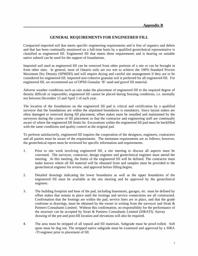
Appendix B
i
GENERAL REQUIREMENTS FOR ENGINEERED FILL
Compacted imported soil that meets specific engineering requirements and is free of organics and debris and that has been continually monitored on a full-time basis by a qualified geotechnical representative is classified as engineered fill. Engineered fill that meets these requirements and is bearing on suitable native subsoil can be used for the support of foundations.
Imported soil used as engineered fill can be removed from other portions of a site or can be brought in from other sites. In general, most of Ontario soils are too wet to achieve the 100% Standard Proctor Maximum Dry Density (SPMDD) and will require drying and careful site management if they are to be considered for engineered fill. Imported non-cohesive granular soil is preferred for all engineered fill. For engineered fill, we recommend use of OPSS Granular ‘B’ sand and gravel fill material.
Adverse weather conditions such as rain make the placement of engineered fill to the required degree of density difficult or impossible; engineered fill cannot be placed during freezing conditions, i.e. normally not between December 15 and April 1 of each year.
The location of the foundations on the engineered fill pad is critical and certification by a qualified surveyor that the foundations are within the stipulated boundaries is mandatory. Since layout stakes are often damaged or removed during fill placement, offset stakes must be installed and maintained by the surveyors during the course of fill placement so that the contractor and engineering staff are continually aware of where the engineered fill limits lie. Excavations within the engineered fill pad must be backfilled with the same conditions and quality control as the original pad.
To perform satisfactorily, engineered fill requires the cooperation of the designers, engineers, contractors and all parties must be aware of the requirements. The minimum requirements are as follows; however, the geotechnical report must be reviewed for specific information and requirements.
1. Prior to site work involving engineered fill, a site meeting to discuss all aspects must be
convened. The surveyor, contractor, design engineer and geotechnical engineer must attend the meeting. At this meeting, the limits of the engineered fill will be defined. The contractor must make known where all fill material will be obtained from and samples must be provided to the geotechnical engineer for review, and approval before filling begins.
2. Detailed drawings indicating the lower boundaries as well as the upper boundaries of the
engineered fill must be available at the site meeting and be approved by the geotechnical engineer.
3. The building footprint and base of the pad, including basements, garages, etc. must be defined by
offset stakes that remain in place until the footings and service connections are all constructed. Confirmation that the footings are within the pad, service lines are in place, and that the grade conforms to drawings, must be obtained by the owner in writing from the surveyor and Sirati & Partners Consultants Limited. Without this confirmation, no responsibility for the performance of the structure can be accepted by Sirati & Partners Consultants Limited (SIRATI). Survey
drawing of the pre-and post-fill location and elevations will also be required.
4. The area must be stripped of all topsoil and fill materials. Subgrade must be proof-rolled. Soft
spots must be dug out. The stripped native subgrade must be examined and approved by a SIRA
-TI engineer prior to placement of fill.

Appendix B
ii
5.
6.
7.
8.
9.
10.
11.
12.
13.
14.
The approved engineered fill material must be compacted to 100% Standard Proctor Maximum Dry Density throughout. Engineered fill should not be placed during the winter months. Engineered fill compacted to 100% SPMDD will settle under its own weight approximately 0.5% of the fill height and the structural engineer must be aware of this settlement. In addition to the settlement of the fill, additional settlement due to consolidation of the underlying soils from the structural and fill loads will occur and should be evaluated prior to placing the fill.
Full-time geotechnical inspection by SIRATI during placement of engineered fill is required.
Work cannot commence or continue without the presence of the SIRATI representative.
The fill must be placed such that the specified geometry is achieved. Refer to the attached sketches for minimum requirements. Take careful note that the projection of the compacted pad beyond the footing at footing level is a minimum of 2 m. The base of the compacted pad extends 2 m plus the depth of excavation beyond the edge of the footing.
A bearing capacity of 150 kPa at SLS (225 kPa at ULS) can be used provided that all conditions outlined above are adhered to. A minimum footing width of 500 mm (20 inches) is suggested and footings must be provided with nominal steel reinforcement.
All excavations must be done in accordance with the Occupational Health and Safety Regulations of Ontario.
After completion of the engineered fill pad a second contractor may be selected to install footings. The prepared footing bases must be evaluated by engineering staff from SIRATI prior
to footing concrete placements. All excavations must be backfilled under full time supervision
by SIRATI to the same degree as the engineered fill pad. Surface water cannot be allowed to
pond in excavations or to be trapped in clear stone backfill. Clear stone backfill can only be used
with the approval of SIRATI.
After completion of compaction, the surface of the engineered fill pad must be protected from disturbance from traffic, rain and frost. During the course of fill placement, the engineered fill must be smooth-graded, proof-rolled and sloped/crowned at the end of each day, prior to weekends and any stoppage in work in order to promote rapid runoff of rainwater and to avoid any ponding surface water. Any stockpiles of fill intended for use as engineered fill must also be smooth-bladed to promote runoff and/or protected from excessive moisture take up.
If there is a delay in construction, the engineered fill pad must be inspected and accepted by the geotechnical engineer. The location of the structure must be reconfirmed that it remains within the pad.
The geometry of the engineered fill as illustrated in these General Requirements is general in nature. Each project will have its own unique requirements. For example, if perimeter sidewalks are to be constructed around the building, then the projection of the engineered fill beyond the foundation wall may need to be greater.
These guidelines are to be read in conjunction with Sirati & Partners Consultants Limited (SIRA
TI) report attached.

Appendix B
iii
Competent Natural Soil To Be Confirmed By SIRATI
Backfill in this area to be as per the SIRATI report
Engineered Fill Full Time Inspection During Placement By SIRATI

Project: SP18-347-10-R2 Geotechnical Investigation Flato Developments Proposed Commercial Development 6710 Hurontario Street, Mississauga, Ontario
SIRATI & PARTNERS CONSULTANTS LIMITED 5
MARCH 5, 2021
Appendix C: Limitations of Report
This report is intended solely for the Client named. The material in it reflects our best judgment in light of the
information available to Sirati & Partners Consultants Limited (SIRATI) at the time of preparation. Unless
otherwise agreed in writing by SIRATI, it shall not be used to express or imply warranty as to the fitness of the
property for a particular purpose. No portion of this report may be used as a separate entity, it is written to be
read in its entirety.
The conclusions and recommendations given in this report are based on information determined at the borehole
locations. The information contained herein in no way reflects on the environment aspects of the project, unless
otherwise stated. Subsurface and groundwater conditions between and beyond the boreholes may differ from
those encountered at the borehole locations, and conditions may become apparent during construction, which
could not be detected or anticipated at the time of the site investigation. The benchmark and elevations used in
this report are primarily to establish relative elevation differences between the borehole locations and should not
be used for other purposes, such as grading, excavating, planning, development, etc. Professional judgement was
exercised in gathering and analyzing data and formulation of recommendations using current industry guidelines
and standards. Similar to all professional persons rendering advice, SIRATI cannot act as absolute insurer of the
conclusion we have reached. No additional warranty or representation, expressed or implied, is included or
intended in this report other than stated herein the report.
The design recommendations given in this report are applicable only to the project described in the text and then
only if constructed substantially in accordance with the details stated in this report.
The comments made in this report on potential construction problems and possible methods are intended only for
the guidance of the designer. The number of boreholes may not be sufficient to determine all the factors that may
affect construction methods and costs. For example, the thickness of surficial topsoil or fill layers may vary
markedly and unpredictably. The contractors bidding on this project or undertaking the construction should,
therefore, make their own interpretation of the factual information presented and draw their own conclusions as
to how the subsurface conditions may affect their work. This work has been undertaken in accordance with
normally accepted geotechnical engineering practices. Any use which a third party makes of this report, or any
reliance on or decisions to be made based on it, are the responsibility of such third parties. SIRATI accepts no
responsibility for damages, if any, suffered by any third party as a result of decisions made or actions based on
this report.
We accept no responsibility for any decisions made or actions taken as a result of this report unless we are
specifically advised of and participate in such action, in which case our responsibility will be as agreed to at that
time. Any user of this report specifically denies any right to claims against the Consultant, Sub-Consultants, their
officers, agents and employees in excess of the fee paid for professional services.
SIRATI engagement hereunder is subject to and condition upon, that SIRATI not being required by the Client, or
any other third party to provide evidence or testimony in any legal proceedings pertaining to this finding of this
report or providing litigations support services which may arise to be required in respect of the work produced
herein by SIRATI. It is prohibited to publish, release or disclose to any third party the report produced by
SIRATI pursuant to this engagement and such report is produced solely for the Client own internal purposes and
which shall remain the confidential proprietary property of SIRATI for use by the Client, within the context of
the work agreement. The Client will and does hereby remise and forever absolutely release SIRATI, its directors,
officers, agents and shareholders of and from any and all claims, obligations, liabilities, expenses, costs, charges
or other demands or requirements of any nature pertaining to the report produced by SIRATI hereunder. The
Client will not commence any claims against any Person who may make a claim against SIRATI in respect of
work produced under this engagement.