report on domestic refrigerating machines 1923 – 1925 library/about/mission and vision/ashrae...
TRANSCRIPT
1
Report on Domestic Refrigerating Machines 1923 – 1925 Written by: Alexander Stevenson Jr. (1892-1946) Assistant to Francis Pratt, Vice President of Engineering General Electric Co. Transcription by: Anne Marie Nagengast Editorial notes added by Bernard A. Nagengast 2004/2005 A Project by the Historical Committee, American Society of Heating, Refrigerating and Air-Conditioning Engineers The original copy of this report was discarded when the Technical Data Library of the General Electric Co. was disbanded. This transcription was based on a badly faded photocopy provided by Ruth Schwartz Cowan, who accessed the original during her research for her book “More Work for Mother” (1983: Basic Books). Due to the poor condition of the photocopy, some lines or words were illegible – in those cases a note was inserted in the transcription: text illegible. Some appendices included graphs or illustrations that were faded beyond recognition – these were not included. In the case where an illustration was identified with a General Electric photograph number, that information was included should a researcher wish to access the originals located in the General Electric Photo Collection at the Schenectady Museum, Schenectady, New York. Historical Significance: Alexander Stevenson’s report is the first comprehensive engineering study of household refrigeration, a rapidly developing field in the early 1920’s. The report, written in 1923, with additions in 1924 and 1925 with many appendices, gives the history of General Electric’s involvement in refrigeration, and has information on most of the household refrigeration units in existence at that time. Much of the information can be found nowhere else. Stevenson was assisted in the project by several staff of General Electric’s Ft. Wayne (Indiana) Division including Walter Goll, Works Manager; Clark Orr, master mechanic and lead engineer; Harvey Crane, field service; Robert Steck, chief engineer and James Woods, former Works Manager. (for additional history see: Linkous, Clovis. 1994. General Electric at Ft. Wayne – A 110 Year History. Baltimore: Gateway Press). The Stevenson report provided the justification for General Electric’s entry into the household refrigerator market.
2
Data Folder No. 1120
Subject DOMESTIC REFRIGERATING MACHINES Nature Complete Data etc. By A.R. Stevenson Aug. 17, 1923 Date filed: Aug. 24, 1923.
GENERAL ELECTRIC COMPANY SCHENECTADY, N.Y. Return promptly to Data Section Files

3
DOMESTIC REFRIGERATING MACHINES Schenectady, N.Y., August 17, 1923 Mr. Gerard Swope, President, New York Office, Dear Mr. Swope:
I forwarded to you on August 14th Mr. Goll’s letter
to me of August 11th commenting on the report compiled by Mr. A. R.
Stevenson, Jr., re above.
After Mr. Stevenson had completed his final draft of the report
he spent over a week at Fort Wayne reviewing it in detail with Messrs,
Goll, Crane, Orr, Wood and Evans, making such changes in the report
at the information brought forth in the conference made desirable.
The report containing the results of a highly skillful, conscientious
and unprejudiced investigation made by Mr. Stevenson over a period
of a little less then 5 months. In regard to this I want to point
out that Mr. Stevenson’s investigations were first directed to ac-
tivities outside of our own Company, and that he did not concentrate
his attention on the Fort Wayne situation until he had thoroughly
absorbed what had been done elsewhere.
I believe that the report contains practically all information
of value currently available which bears upon the business in domes-
tic refrigerating machines.
As recommended in the report, the statements submitted with re-
spect to factory cost, selling expenses, profits and look-up, should
be checked and revised by the General Electric Company’s Comptroller
if we decide to process further in the exploitation of the domestic
refrigerating machine business. In this connection I note that

4
-2-
in Table VI, Summary, Report #2, Parts III and IV, Manufactur-
ing and Financial, factory inventory material and apparatus is
included as a part of the lockup of the selling company, but
in accordance with our established practice it would be include-
ed in the factory accounting. In connection with the latter
an allowances of 140% on direct labor has been made in the report
for factory overhead.
I am sending to you today a copy of the Report compris-
ing three volumes.
The first volume constitutes the Report and the second
and third volumes appendices.
Volume I is divided into three parts consisting of
Index, Report #1, Summary and Conclusions; Report #2, Histor-
ical Introduction – Part 1, Commercial, Part II, Engineering,
Parts III and IV, Manufacturing and Financial.
I hope that you will read Report I and as much of
Report 2, Parts I to IV, inclusive, as your interest in this
subject may lead you to do.
I think that the information given in Volume II and
III may be looked upon largely as of reference value.
You will probably recall that I requested Mr. Steven-
son to make this report as the outcome of conversations with
Mr. Young and later with yourself last March, at which time
Consideration was being given to a suggestion made by
Mr. F. S. Hunting that we should turn over to Mr. Kettering
of the Dayton Research Laboratories of the General Motors Com-

5
-3-
pany a sample of our latest design of OC-2 domestic refrigera-
ting machine made at the Fort Wayne Works. For certain
reasons which I stated at the time, I objected to this being
done and Mr. Young replied that, considering the probability
of the General Electric Company ultimately organizing a sub-
sidiary company for exploiting domestic electrical devices,
he deemed it important that we should keep in close touch with
the domestic refrigerating machine business. I understood at
the time that he had in mind the possibility of such a subsid-
iary company as that above referred to selling domestic re-
frigerating machines manufactured by the General Motors Com-
pany.
I then made the statement that, in view of such circums-
tances, it seemed to me that we should encourage the Fort Wayne
Works to continue its development as I believed that their de-
signs and manufacturing experiences in this line were superior
to those of any one else then in the field.
While it is a fact that the Fort Wayne Works have not
been carrying on aggressive developmental work for some time
past, yet certain important improvements have been introduced
into their designs, and I feel even under these circumstances that
Mr. Stevenson’s report essentially substantiates the statement
which I made at that time.
I am confident that we are today in a stronger position
than any one else in this country to handle the engineering and
manufacturing activities of a domestic refrigerating machine

6
-4-
business, and the question of the desirability of the General
Electric Company exploiting this business is largely a matter
of financial, sales and servicing arrangements.
There reads through Mr. Stevenson’s report the important
fact that all existing practice carries a more than normal
hazard of being revolutionized by inventions of a fundamental
character. So many active minds throughout the country are
being directed to the solution of these problems that it would
be perhaps surprising if some such inventions did not material-
ize. This, of course, introduces a hazard into the business
of more than ordinary magnitude.
In considering this subject I think that I should state
my conviction that time is decidedly an element in the situa-
tion, that the business is a rapidly evolving one, making real
strides from the developmental to the commercial stage, and that
each year finds a limited number of manufacturers more thorough-
ly established in the market and gathering into their services
the best selling agencies, including the central stations. With
relation to this point of view, I also recall that Mr. R.
McAllister Lloyd in conversation with me about two months ago
expressed the opinion that the art had now advanced to such a
state of stabilization as to make it an opportune time to enter
into commercial exploitation. While I should not be prepared
to accept Mr. Lloyd’s opinion in this matter without reserve,
yet I do put some weight upon the fact that he has been active-
ly interested in domestic refrigeration for a number of years

7
-5-
past.
It is well understood that heavy financial losses
have been incurred in the exploitation of this business, but
I suggest that the problem for the General Company to consider
is whether the time has not arrived when this business can be
made profitable. It seems to me that Mr. Stevenson has treat-
ed this phase of the situation in a circumspect and judicial
way.
While there are many detailed references in the Report
indicating the value of our design and manufacturing exper-
ience at Fort Wayne, it does not seem to me necessary that I
should make further reference to them in this letter.
I strongly urge that Mr. Stevenson’s report, concurred
in by our people at Fort Wayne, should receive at this time
the serious consideration which I feel it and the subject to
which is refers deserve.
If we have in mind providing in the near future as
organization particularly adapted for the effective commercial
exploitation and financing of the domestic electrical devices,
and believe that a domestic refrigerating machine is a logical
component of such a line of devices, I would recommend that
we should again take up in a comprehensive and affective way
development work on domestic refrigerating machines at Fort
Wayne, supporting the effort with such assistance as our lab-
oratories and experts located elsewhere could give.
Meanwhile, I will take the responsibility of approving
in behalf of the Manufacturing Committee an appropriation of
8
-6-
$1000 for the purpose of demonstrating so far as possible
whether there are merits in the mercury injector suggested by
Mr. Hewett, on which preliminary calculations have been made
by Mr. Alger, as I believe that more definite information in
regard to this has such possible value to the General Company
as to justify this small expenditure even though the chance
of success is remote.
Very truly yours,
FRANCIS O. PRATT
FCP/ JSH-Jr
CDYoung Dictated by Mr. Pratt
KWRiceJr Signed in his (text illegible)
ARJackson
WGoll
ARStevenson
Publication Bureau
9
DOMESTIC REFRIGERATION
Report #1
SUMMARY AND CONCLUSIONS
Report #2
GENERAL SURVEY
Report #3
APPENDICES CONTAINING DETAILED INFORMATION
Complied and written by
(signed) A. R. Stevenson, Jr
Concurred in
(signed) Walter Goll
H E Crane
Clark Orr
10
INDEX
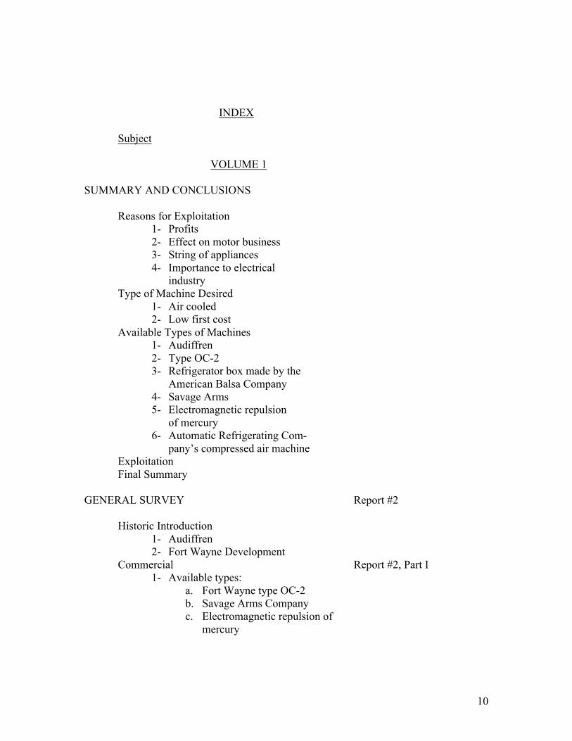
Subject VOLUME 1 SUMMARY AND CONCLUSIONS Reasons for Exploitation
1- Profits 2- Effect on motor business 3- String of appliances 4- Importance to electrical
industry Type of Machine Desired
1- Air cooled 2- Low first cost
Available Types of Machines 1- Audiffren 2- Type OC-2 3- Refrigerator box made by the
American Balsa Company 4- Savage Arms 5- Electromagnetic repulsion
of mercury 6- Automatic Refrigerating Com-
pany’s compressed air machine Exploitation Final Summary GENERAL SURVEY Report #2 Historic Introduction
1- Audiffren 2- Fort Wayne Development
Commercial Report #2, Part I 1- Available types:
a. Fort Wayne type OC-2 b. Savage Arms Company c. Electromagnetic repulsion of
mercury
11
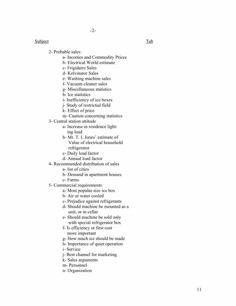
-2- Subject Tab 2- Probable sales: a- Incomes and Commodity Prices b- Electrical World estimate c- Frigidaire Sales d- Kelvinator Sales e- Washing machine sales f- Vacuum cleaner sales g- Miscellaneous statistics h- Ice statistics i- Inefficiency of ice boxes j- Study of restricted field k- Effect of price m- Caution concerning statistics
3- Central station attitude a- Increase in residence light- ing load b- Mr. T. I. Jones’ estimate of Value of electrical household refrigerator c- Daily load factor d- Annual load factor 4- Recommended distribution of sales a- list of cities b- Demand in apartment houses c- Farms 5- Commercial requirements
a- Most popular size ice box b- Air or water cooled c- Prejudice against refrigerants d- Should machine be mounted as a unit, or in cellar e- Should machine be sold only with special refrigerator box f- Is efficiency or first cost more important g- How much ice should be made h- Importance of quiet operation i- Service j- Best channel for marketing k- Sales arguments m- Personnel n- Organization
12
-3-
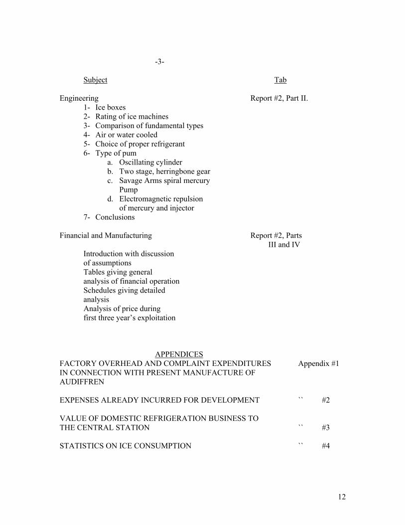
Subject Tab
Engineering Report #2, Part II. 1- Ice boxes 2- Rating of ice machines 3- Comparison of fundamental types 4- Air or water cooled 5- Choice of proper refrigerant 6- Type of pum
a. Oscillating cylinder b. Two stage, herringbone gear c. Savage Arms spiral mercury
Pump d. Electromagnetic repulsion
of mercury and injector 7- Conclusions
Financial and Manufacturing Report #2, Parts III and IV Introduction with discussion
of assumptions Tables giving general analysis of financial operation Schedules giving detailed analysis Analysis of price during first three year’s exploitation
APPENDICES
FACTORY OVERHEAD AND COMPLAINT EXPENDITURES Appendix #1 IN CONNECTION WITH PRESENT MANUFACTURE OF AUDIFFREN EXPENSES ALREADY INCURRED FOR DEVELOPMENT `` #2 VALUE OF DOMESTIC REFRIGERATION BUSINESS TO THE CENTRAL STATION `` #3 STATISTICS ON ICE CONSUMPTION `` #4

13
-4- Subject Tab REPLIES FROM SUPERINTENDENTS OF WATER WORKS Appendix #5 ICE BOXES (Includes Climate Maps) `` #6 DISCUSSION OF THE FACTORS WHICH INFLUENCE THE RATING OF A DOMESTIC REFRIGERATING MACHINE `` #7 ANALYSIS OF TESTS ON TYPE OC-2 FORM F MACHINE `` #8 DISCUSSION OF POSSIBLE REDESIGN OF THE FORT WAYNE TYPE OC-2 MACHINE FOR AIR COOLING `` #9 THEORETICAL ANAYLSIS AND COMPARISON OF ABSORPTION MACHINES `` #10 COMPARISON OF VARIOUS REFRIGERANTS `` #11 BALSA REFRIGERATOR BOX `` #12 FORT WAYNE TYPE OC-2 REFRIGERATING MACHINE `` #13 SAVAGE ARMS REFRIGERATING MACHINE `` #14 ODIN REFRIGERATING MACHINES `` #15 WATER VAPOR MACHINE SUGGESTED BY MR. A. R. DODGE `` #16 SYSTEM OF REFRIGERATION SUGGESTED BY MR. R. W. DAVENPORT OF DETROIT `` #17 LIST OF PEOPLE INTERVIEWED `` #18 LIST OF COMPANIES VISITED `` #19 M. V. ARNOLD’S MACHINE `` #20 AUDIFFREN SOLD BY JONES MANVILLE COMPANY `` #21 AUDIFFREN SOLD BY AUDIFFREN COMPANY `` #22

14
-5- Subject Tab
AUTOFRIGO Appendix #23 BAUER & WAHL `` #24 BRUNSWICK `` #25 CHILRITE `` #26 COLDAY `` #27 COLDMAKER `` #28
COMMON SENSE `` #29
COPELAND `` #30
CORBLIN COMPRESSOR `` #31
FEDERATED ENGINEERS DEVELOPMENT CORPORATION `` #32
FREEZERATOR `` #33
FRIGIDAIRE `` #34
FRIGIDOR `` #35
FRIGOR `` #36
FRIGORE `` #37
GLACIFER COMPANY `` #38
GOETZ ICE MACHINE `` #39
HAVENSTRITE DEVELOPMENT `` #40
GEORGE HORANA `` #41
ISKO COMPANY `` #42
KARGE LABORATORIES `` #43
KEITH ELECTRIC REFRIGERATOR `` #44
KELVINATOR `` #45
PROFESSOR KEYES’ MACHINE `` #46
KNICKERBOCKER ICE COMPANY `` #47

15
-6-
Subject Tab
KOLD KING Appendix 48
C. H. LEONARD `` 49
LIPMAN `` 50
MATHES & COMPANY `` 51
McCLELLAN REFRIGERATOR `` 52
MACLAREN FROZEN AIR MACHINE `` 53
MOTORFRIGERATOR `` 54
F. W. NIEBLING `` 55
NORWALK `` 56
OTTO `` 57
RADIANT `` 58
RAPIDE `` 59
REFRIGO `` 60
RUMPLER `` 61
SANITARY (Changed to Frankenburg) `` 62
SERVEL `` 63
C. E. TRIPP’S MACHINE `` 64
UNIVERSAL ICE MACHINE `` 65
UTILITY ICE MACHINE `` 66
FRED W. WOLF COMPANY `` 67
WILLIAMS SIMPLEX REFRIGERATOR `` 68
MR. HUNTING’S REPORT OF REFRIGERATING
MACHINE DEVELOPMENT AT FORT WAYNE WORKS `` 69
16
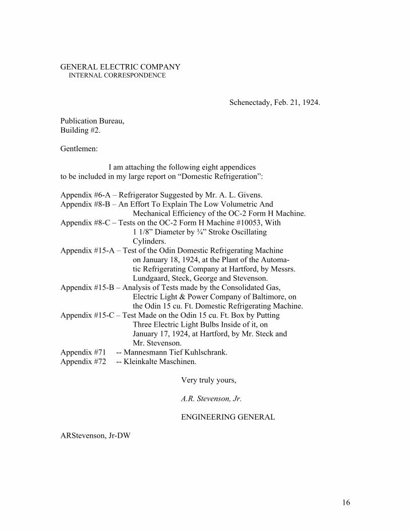
GENERAL ELECTRIC COMPANY INTERNAL CORRESPONDENCE Schenectady, Feb. 21, 1924. Publication Bureau, Building #2. Gentlemen: I am attaching the following eight appendices to be included in my large report on “Domestic Refrigeration”: Appendix #6-A – Refrigerator Suggested by Mr. A. L. Givens. Appendix #8-B – An Effort To Explain The Low Volumetric And Mechanical Efficiency of the OC-2 Form H Machine. Appendix #8-C – Tests on the OC-2 Form H Machine #10053, With
1 1/8” Diameter by ¾” Stroke Oscillating Cylinders. Appendix #15-A – Test of the Odin Domestic Refrigerating Machine on January 18, 1924, at the Plant of the Automa- tic Refrigerating Company at Hartford, by Messrs. Lundgaard, Steck, George and Stevenson. Appendix #15-B – Analysis of Tests made by the Consolidated Gas, Electric Light & Power Company of Baltimore, on the Odin 15 cu. Ft. Domestic Refrigerating Machine. Appendix #15-C – Test Made on the Odin 15 cu. Ft. Box by Putting Three Electric Light Bulbs Inside of it, on January 17, 1924, at Hartford, by Mr. Steck and Mr. Stevenson. Appendix #71 -- Mannesmann Tief Kuhlschrank. Appendix #72 -- Kleinkalte Maschinen. Very truly yours, A.R. Stevenson, Jr. ENGINEERING GENERAL ARStevenson, Jr-DW

17
GENERAL ELECTRIC COMPANY INTERNAL CORRESPONDENCE Schenectady, Feb. 21, 1924. Publication Bureau, Building #2. I am attaching the following appendices which should be included in your report on Domestic Refrigeration: APPENDIX #12-A - Information Furnished by Mr. Stuart Otto on Balsa Box. APPENDIX #13-A - Corblin Compressor. APPENDIX #14-A - Tests on the Savage Arms Machine. APPENDIX #15-A - Addition – Thermometer Corrections. APPENDIX #15-D - Tests of the Odin Machine #143 Made by Messrs. Lundgaard and Stevenson on February 4 &5, 1924. APPENDIX #44-A - Information Furnished by Mr. Stuart Otto on Keith Machine. APPENDIX #46-A - Information Furnished by Mr. Stuart Otto on Keyes Machine. APPENDIX #57-A - Otto Refrigerating Machine. APPENDIX #71-A - Information Furnished by Mr. Stuart Otto on Mannesmann Machine. APPENDIX #73 - Polaris. APPENDIX #74 - Haccius & Bischof.
A.R. Stevenson, Jr.
ENGINEERING GENERAL
ARStevenson, Jr-DW

18
VOLUME I
Report #1
SUMMARY AND CONCLUSIONS
************
REASONS FOR EXPLOITATION
It is recommended that the General Electric Company
should undertake the further development of an electrical house-
hold refrigerator as an addition to their sting of appliances,
and because widespread adoption will increase the revenue of the
central stations, thus indirectly benefiting the General Electric
Company. But, the General Electric Company should not enter this
field in the hopes of immediate profits from the sale of these
machines. For some years to come, the development and complaint
expenses will probably eat up all the profits.
On page 36 of the July 1923 number of “Ice and Refriger-
ation” in the “Report of the Activities of the Trade Development
Bureau of the National Association of Ice Industries” there is
the following statement:
“More than sixty million dollars have been spent by
developers of the Household Machine”.
This is probably a very inaccurate statement, but one
cannot think of even one-third this amount having been spent
without being impressed with the necessity for caution in enter-
ing this field. It would seem as though enough money and
brains had been spent to prove the difficulty of the problem.

19
Four general questions which must be considered in
deciding whether it is advisable for the General Electric
Company to undertake the exploitation of an electric household
refrigerator are profits, effect on motor business, string of
appliances and importance to electrical industry.
#1 Profits
No thoroughly reliable and reasonably inexpensive
domestic refrigerating machine has yet been developed by any
of the many companies engaged in this enterprise. During the
developmental stage, it is easier to lose than to make money.
Therefore, the General Electric Company should not undertake this
business in the hope of immediate profits.
On the other hand there is a large and growing
demand for these machines. This is discussed in part #1 of
report No. 2, where it is estimated that all manufacturers
together will sell about 40,500 machines this year. It is also
estimated that the business will increase to 138,000 machines
sold by all manufacturers in 1934.
It is believed that the General Electric Subsidiary
Company could not hope to obtain more than a fifth of this total
business.
On these assumptions, the G. E. Subsidiary could
In 1934 do a gross business of $7,320,000 sales of domestic
refrigeration machines to dealers. (See table #1, page #4,
part #1 of Report No. 2.)
In part 3 of Report No. 2, there is the analysis
of the operation of a separate selling organization exploiting
domestic refrigerating machines. That analysis would

20
seem to indicate that after a preliminary year devoted to
development and the three following years of commercial exploita-
tion, there would be a substantial return on the investment and
most of the development could be liquidated. Predictions of this
kind are almost purely guess work, but the details are given in
Reports III and IV so that the reader can determine for himself
whether the guesses are based on conservative assumptions. Of
course, in actual practice the figures might be divided differentely.
It might even be decided to lower the selling price in order to
facilitate sales. This might lessen the sales expense, but it
would probably mean smaller profits and consequently a longer
period might be required to liquidate the development.
The money “locked up” at the end of each year
Is as follows:
Lockup Average Profit Profit expressed at end Invest- as percentage of
of year ment average invest- During ment. Year Year of prelimin- ary development $126,047* $107,297 First year’s exploitation 228,272x y 177,159 -$13,125 -7.4 % Second year’s exploitation 406,172x 317,172 20,850 6.6 % Third year’s Exploitation _631,722x 518,897 114,850 22.3 % _ 1,120,525 122,575 AVERAGE 280,131 30,644 10.8 % _________________________ Foot-note*: This figure includes $88,647 already spent on the development of the water cooled type OC-2 machine. At some (Cont’d on next page)

21
Of course, this is all imaginary, but the
schedules of operation are given in detail in part III of Report
No. 2. By referring to them, it is possible to form an opinion
as to how conservative the estimate is.
These figures should be submitted to the
Comptroller’s Department for revision before they are accepted
as final. We are not accountants and we do not have the accurate
information concerning probable allocations of General Electric
Company corporate expenses, etc.
It is felt that the operation of such a com-
pany will depend largely on the ability of the manager and his
associates. If it is contemplated having such a company run by
one of the G. E. department heads in his spare time, it is felt
that it may not succeed. Some one big man must devote his whole
time to the job and be held entirely responsible for the success
or failure of the domestic refrigeration business.
2. Effect on Motor Business
Mr. F. M. Kimball feels that $250,000. worth
of small motor business with refrigerating manufacturers will be
______________
Foot-note* Cont’d: later time, this water cooled development might be of use in entering the field of refrigeration for ice cream stores, butcher shops, restaurants, etc., where there is quite a demand for machine with capacities from 250 to 400 lbs. of ice per twenty-four hours. Foot-note (x): These figures include money tied up in material, goods in transit and warehouse, accounts receivable, and unliqui- dated development. Foot-note (y) Includes the accumulated loss.
22
seriously prejudiced if the General Electric Company enters the
field of domestic refrigeration.
But, Mr. A. J. Francis feels that the manu-
facturers of refrigerating machinery would not object if the
General Electric Company marketed a domestic refrigerating
Machine through some subsidiary company and not under the
General Electric name.
After interviewing the officials of many of
the companies engaged in the manufacture of domestic refrigerat-
ing machines, it is our impression that they would be inclined
not to object to a strong competitor who would help educate
public opinion to the idea of mechanical refrigeration.
There is also a possibility that in entering
the domestic refrigerating field the General Electric Company
might secure patents. The motor business might possibly be
assisted by offering to license other companies on the condition
that they purchase General Electric motors.
If the General Electric Company should develop
and put on the market a domestic refrigerating machine of such
superior quality as to create a prestige in this field , other
manufacturers might want to use G. E. motors in order to partly
share this prestige.
At present, the General Electric Company is
not getting its proper share of the motor business of the manu-
facturers of domestic refrigerating machines.
Our recommendations would be that this
question of motor business should not be allowed to stand in the

23
way, if for other reasons it should seem advisable to enter the
domestic refrigerating field.
3. String of Appliances
It is increasingly being realized that the
“contact with the customer” is the most important feature in
merchandising. After sufficient sales effort has been made to
establish the “contact with the customer”, it is very important
that the salesman have a “string of appliances” to sell. If the
customer does not want an electric range, perhaps he will con-
sider the purchase of a washing machine, or perhaps he is inter-
ested in an electrical refrigerator.
An electrical household refrigerator is a
necessary part of any broad scheme for merchandising electrical
household appliances.
One of the best reasons for the General Elec-
tric Company’s entering the domestic refrigerating machine busi-
ness is to complete its string of appliances. If the whole line
of General Electric appliances eventually sold under the same
trade name, each appliance in the home should be a silent sales-
man for the rest of the line.
4. Importance to Electrical Industry
The General Electric Company gains by anything
which benefits the electrical industry.
There is no doubt but than the electrical
household refrigerator is the best household appliance from the

24
standpoint of revenue to the central stations. It is estimated
that in 1934, there will be 560,000 domestic refrigerating
machines in operation in the United States. At 2.2 KW-hrs. per
day and 5 cents per KW-hr., the annual revenue from each machine is
about $40.00. This makes a revenue of $22,400,000. to the
central stations. Probably the total central station income
in 1935 will be $1,500,000,000. This would indicate that the
domestic refrigeration machines might form about 1½ % of the
total revenue.
If the revenue from residence lighting, etc.,
is 16% of the total, then the domestic refrigeration machine
might form about 10% of the residence revenue.
For further details see part 1 of Report #2,
page 23.

25
_TYPE OF MACHINES DESIRED_
In report #2, the proper design of a domestic
refrigerating machine is discussed in detail as regards
commercial requirements and engineering possibilities. Let
it suffice to say here that:
1. The ideal refrigerating machine should be
air cooled. It should also be mentioned that the electric
power bill of the air cooled machine would be about $1.30 more
in six months than the water cooled machine, but that approximate-
ly 86 cents worth of water would be saved. (See appendix #7, page #5).
Since the General Electric Company is entering
this field for the benefit of the central station, it would
seem wise to exploit a machine in which the total revenue
would accrue to the central station rather that partly to
the water works.
This question of air cooling versus water
cooling is discussed in detail on page #33 of part #1 of Report
#2.
2. Since at present prices the interest and
depreciation changes are greater that the cost of power, it
seems evident that it is more important to obtain a low first
cost than high efficiency.
26
AVAILABLE TYPES OF MACHINES_
1. The General Electric Company is at present
Building the most reliable small ice machine at present on
the market. Some of the Audiffren machines have lasted
ten years without ever being opened for repairs. There
are very few pieces of machinery that can compare with such
a record. On the other hand, it seems impossible to build
a machine of the Audiffren design which could be sold with
a refrigerator box for much less than $1000.
Due to the high price and consequent small
production, the overhead on these Audiffren machines is so
high that the business is no longer profitable to the General
Electric Company. For details, see appendix #1, page #1.
If the General Electric Company decides to
exploit a domestic refrigerating machine the additional
production would help absorb the overhead and thus insure
lower costs on both the domestic and the Audiffren machine
that would otherwise be possible. If we are to continue
the manufacture of the Audiffren machine we should make a
new contract with the Audiffren Company which would permit
us to do this work at a profit.
The machine now being developed by the Savage
Arms Company of Utica, N.Y., may prove successful and a
serious competitor of both the Audiffren and the OC domestic
machines to be discussed in the following section. This
possibility might well be borne in mind in considering a new
contract with the Audiffren Company.

27
2. The Fort Wayne OC 2 (domestic water cooled)
machine has in it the essential features which have been so
well proven out in the Audiffren design, such as the eccentrics,
the oscillating cylinders, the valves and the system of
lubrication. We believe that these elements combine to make
the most reliable water cooled machine available for production.
In addition the OC 2 is simpler and less expensive
to manufacture than the Audiffren design. However, it is
water cooled and the commercial demand is for air cooling.
It is believed by those most familiar with the past history
of this development that the type OC 2 machine can easily be
redesigned for air cooling and if placed on the market in the
near future would be the best machine available. It is
therefore recommended that work start immediately upon the
task of modifying this OC 2 machine to permit of air cooling
and be prosecuted vigorously. The following program is
recommended:
1. That tests be undertaken on the OC 2 machine modified
for air cooling and that when sufficient data have been secured.
2. The drawings and patterns be made for an air cooled
design.
3. Six models be made and placed in test not only in the
shop but also in the homes of those concerned with this work
at Fort Wayne.
We have no doubt that the OC 2 machine can be
modified for successful operation as an air cooled device,

28
but we feel very positive that this design should be very
thoroughly worked out and proven before a commercial program
is undertaken. (We feel that the domestic refrigerating
machine business is in its developmental stage and that
in all probability some decided and radical improvement
may be made in this field which might supersede all
present types.) The Savage Arms development already
mentioned is an example of the possibilities along this
line. Any scheme for exploitation therefore must
include in its budget a very liberal development account
or it is doomed to failure.
3. It is recommended that refrigerator boxes be
purchased from the American Balsa Company. Their box is
far superior to any other which can be obtained for the
same price. (See Appendix #12).
4. The Savage Arms Company is about to put on the
market a domestic refrigerating machine which employs a
very novel type of mercury pump. We believe this pump
may have great possibilities, but the Savage Arms
machine is still a laboratory model and would have to be
completely redesigned in order to make a good production
machine. (This machine is described in detail in
Appendix #14)
We recommend that every effort be made to secure for

29
test a model of the Savage arms development and pending these
tests an option be taken for a license to manufacture under
their patents.
5. There is an expired patent #757,393 which
covers a refrigerating machine in which the refrigerant is com-
pressed by means of mercury injection. The mercury is pumped
by electro-magnetic repulsion.
Recently, Mr. J. R. Hewett has suggested a
similar scheme.
Mr. Alger of the Induction Motor Department
has calculated a possible efficiency of about 30 percent for a
motor through which the mercury could be pumped by magnetic
repulsion.
The overall efficiency of the Fort Wayne type
OC-2 motor and compressor is about 14½ %.
Therefore, if an injector could be built with
an efficiency of approximately 50% (which seems unlikely) #, there
is a slight chance of equaling the overall efficiency of our
present machine.
It should be possible to build such a machine
cheaply, and it would have a great advantage in having no moving
parts. This would eliminate the problems of noise and lubrication.
____________________
Foot-note (#): When a steam injector is used for feeding water into a boiler, the thermal efficiency is nearly 100% because the heat content of the steam is returned to the boiler. But, when a steam injector is used for pumping water, the latent heat of condensation of the steam is wasted in uselessly warming up the water and the efficiency is from one to two percent. We have been unable up to date to find any data on a mercury injector where the question of latent heat of condensation would not enter.

30
Of course, the chance of success is slight. Even if success is
possible, considerable research and development will be required
before it is attained.
We would recommend that this investigator be
pushed far enough to determine what the possibilities are.
6. The Automatic Refrigerating Company of Hart-
ford have gotten out a domestic refrigerating machine, the “Odin”,
which uses air for the refrigerant. (See appendix #15). This
machine is interesting, but we are afraid it is inherently ex-
pensive and inefficient.
We would recommend that one of these be pur-
chased for investigation and test.
7. Mr. R. W. Davenport of Detroit has suggested
a system of refrigeration which is described in appendix #17.
This is chiefly interesting because the Detroit Edison Company
thinks so highly of it. They say that Mr. Charles M. Schwab,
Mr. Carrier of the Air Conditioning Company, and the National
Association of Ice Industries, are all much interested in this system.
Mr. Davenport believes his invention is worth one
million dollars, but we do not believe it is a necessary part
of a domestic refrigerating machine. However, experiments should
be conducted along the lines outlined in appendix #17.
8. Professor Keyes of Massachusetts Institute of
Technology has developed, and is putting out through the National
Automatic Refrigerating Company, an absorption refrigerating
machine. (See appendix #46.) The is far superior to any of
the other absorption machines on the market. Its disadvantages are:
1. It uses ammonia against which there is a
prejudice.
2. It is inefficient
3. It is water cooled

31
Its advantages are:
a. Noiseless
b. Perhaps inexpensive to build.
We would recommend that we purchase one of these
for investigation and test.
EXPLOITATION.
Since to complete a “string of appliances” was one
of the two reasons for entering this field, this whole
program hinges on the formation of one subsidiary company to
market all domestic appliances. A program for exploitation is discussed in Report #2.
FINAL SUMMARY
Reports #2 and #3 include a complete discussion
of the whole subject together with detailed information.
In case the foregoing recommendations are not
acceptable, the data in Reports #2 and #3 are available for
a study leading to perhaps revised recommendations.
Date Aug 8, 1923 Signed A. R. Stevenson Jr.
Walter Goll
H E Crane
Clark Orr

32
Report #2
GENERAL SURVEY
*********
HISTORICAL INTRODUCTION.
1. Audiffren
In 1911, Mr. Griscom purchased certain rights under
the patents of the Audiffren Singrun machine, formed the American
Audiffren Company, made a contract with the General Electric
Company to build these machines, and with the Johns-Manville
Company to sell them. A rough description of this Audiffren
machine is given in appendix #21, Vol. III.
Due to the high price, no great volume of
business has ever been done by the Audiffren Company. The
General Electric Company has manufactured to date 2510 Audiffren
machines.
During the last six years, 1917-1922, the following
machines were manufactured and sold.
Year No. Sold No. Manufactured 1917 309 302 1918 417 432 1919 273 284 1920 406 362 1921 64 150 1922 167 105____________ Average 275 275
This year’s output will probably be in the
neighborhood of 275.
-1-

33
The overhead resulting from this small production
is very high. (See appendix #1, Vol. II)
The Fort Wayne factory feels that the Audiffren business is
not profitable unless the production of refrigerating machines
can be increased.
It was felt that the production of refrigerating
machines could probably be increased by marketing a domestic
refrigerating machine, because there is quite a large and
increasing demand for artificial refrigeration in the home.
Unfortunately, the cost of the Audiffren cannot
be decreased by making it smaller. The Audiffren Company
estimate that their smallest size ice machine, complete with
a ten or twelve cubic foot ice-box, could not be sold for
less that about $900.00 . (For details, see appendix #22,
Vol. III.) It would be difficult to do a large volume
of business with such a high priced machine.
2. Fort Wayne Development
Realizing that the Audiffren machine is in-
herently too expensive, the General Electric engineers in
charge of its manufacture decided, about 1917, to attempt
the design of a less expensive domestic refrigerating machine.
After several preliminary trials, the type OC-2
machine was developed. A brief description of this machine is
given in appendix #15, Vol. II. Mr. Hunting’s report of
January 31st, 1922, gave such a complete description of the type
OC-2 machine that it seemed unwise to cover the same ground again.
-2-

34
During the last few years, most of the defects of the type OC-2
machine have been overcome one at a time.
At present, the type OC-2 machine is probably the
best water cooled domestic refrigerating machine available.
About thirty of these machines have been built
and about twenty-two machines are in service. At the end of
1922, these on consignment were valued at $6,598.95.
We believe the type OC-2 machine can be resigned
for air cooling without much difficulty. In the commercial and
financial discussion which follow in parts 1 and 3 of this report,
it is indicated that the type OC-2 machine could be sold
complete with a refrigerator box having 7 cubic feet food storage
capacity for a price of $593.00. This price includes freight
from Fort Wayne to New York and complete installation in the
customer’s home.
This price compares very favorably with that
of the Frigidaire machine put out by the Delco Light Company.
The Albany agent of this company told me that their Model B-9,
having 9 cubic feet food storage capacity and selling for $595,
is their most popular size machine. This price of $595, is
f.o.b. Dayton, and does not include freight or installation.
Also, the B-9 machine is a water cooled machine, so that the
installation charge would probably be $30, for the plumber, in
addition to wiring, etc.
The question arose as to whether the General
Electric Company should exploit this type OC-2 machine.
-3-
35
About March 20, 1923, an investigation of the whole field of
domestic refrigerating was undertaken at the request of Mr.
F. G. Pratt.
The subject naturally falls under four main
heads: -
I Commercial.
II Engineering.
III & IV Financial and Manufacturing.
The commercial, engineering, financial, and
manufacturing aspects are so closely interwoven that it has been
impossible to draw definite lines of demarcation between them.
It was recommended in Report No. 1 that the domestic refrigerating
business should be handled as part of a large Domestic
Appliance Company. The organization of this larger company
is beyond the scope of this report. Therefore, the financial
and manufacturing questions in part 3 were discussed on the
assumption of the formation of a separate sales organization.
This makes a clear profit and loss statement.
It was felt, if an analysis of the domestic
refrigeration business with a separate sales organization showed
reasonable returns on the investment, that it would be reasonable
to consider it a profitable department for inclusion in a large
domestic appliance corporation.
-4-

36
REPORT #2
PART 1
**********
COMMERCIAL
1. Available Types
The General Electric Company might undertake
the exploitation of the following:
a. Fort Wayne type OC-2
Up to date about $88,547.00 has been spent in
the development of this machine, and an additional development
of about $41,165.00 would be required to put it on the market.
The following table shows the items of cost, overhead, profits,
discount, etc.
The operation during the second year’s ex-
ploitation has been taken as typical.
Materials, each - - - - - - - - - - - - - $ 87.13 ) Schedule Labor, each - - - - - - - - - - - - - - - 28.28 ) “H” 140% Expense - - - - - - - - - - - - - 39.59 ) Part III Factory cost - - - - - - - - - - - - - - - $ 155.00 Allocating of G.E.Co. general corporate expenses, 10% - - - - - 15.50 ) Manufacturing profit to cover ) Table II Investment in plant facilities, ) Part III 10% - - - - - - - - - - - - - - - - - - - 15.50 ) Factory bills machine at - - - - - - - $ 186.00 General commercial expenses of subsidiary company or depart- ) Table III mental organization, 10.4% - - - 19.30 ) Part III
Gross commercial cost, not in- cluding development - - - - - - - - $ 205.30 Profit, 10.2% of gross commercial- 20.85 ) Table V ) Part III Development, 17.6% of factory billing - - - - - - - - - - - - - - - - - 32.75 ) Table I District pays for machine - - - - - - $ 258.90

37
-2- District pays for machine - - - - - - $ 258.90 ) Schedule FF District pays for refrigerator box - 80.00 ) Part III
$338.90
District selling expense, 28.7% of selling price to central ) Table IV station - - - - - - - - - - - - - - - - - - 141.35 ) Part III Selling price to central station - - - $ 480.25 ) Schedule Y Discount to central station, 15%- - 84.75 ) Part III Total selling to customer- - - - - - - $ 565.00
The various percentages used in making up the
above price are explained in detail in Report No. 2, Part III,
“Financial”.
b. In report #1 it was recommended that a
Savage Arms machine be purchased for rest and that an option be
obtained on a license for its manufacture. If these tests should
be successful and if a satisfactory license agreement could be
obtained, it is possible that the manufacture of this machine
might be undertaken.
c. There is also a faint possibility that the
experiments being carried on in the Research Laboratory on an
injector pump run be electromagnetic repulsion of mercury may
ultimately lead to a simpler and more inexpensive contrivance
than the above.
The general commercial situation will be reviewed
from the standpoint of the exploitation of the Fort Wayne
type OC-2 machine because it is the machine which we believe offers
the most immediate promise of success.

38
-3- 2. Probable Number of Sales The General Electric Company would not want to sell more than one hundred machines the first year and one thousand the second. If everything went well the first two years, the sales would thereafter be pushed as hard as possible.
a. We estimate the following sales.

39
-4-
TABLE #1 ________________________________________________________________________ ________________________________________________________________________ Gross Selling Price Number Selling Sales to of Machine G.E.
Of Price Ultimate Alone to Gross Year Machines Complete Customer Dealer Sales . 1st (1924) 100 $ 592.97 $59,297.00 $ 421.21 $ 42,000.00 2nd (1925) 1,000 565.00 565,000.00 400.00 400,000.00 3rd (1926) 3,000 540.00 1,620,000.00 194.00 1,150,000.00 4th (1927) 6,000 520.00 3,120,000.00 370.00 2,210,000.00 5th (1928) 9,600 495.00 4,750,000.00 352.00 3,380,000.00 6th (1929) 13,000 470.00 6,110,000.00 334.00 4,350,000.00 7th (1930) 15,900 445.00 7,100,000.00 316.00 5,050,000.00 9th (1931) 18,200 420.00 7,650,000.00 300.00 5,420,000.00 9th (1932) 21,000 400.00 8,400,000.00 284.00 6,000,000.00 10th (1933) 27,600 375.00 10,300,000.00 267.00 7,320,000.00 This information is shown graphically on curve H-99399. NOTE:- Since the preparation of this table it was found advisable to spend an additional year in development before starting exploitation. This would make the dates one year later. (see diagram)

40
-5- The preceding estimate was arrived at from
a study of incomes, ice statistics and comparison with other
commodities, as follows.
1. Although the price of this machine is
over $500.00, it is hoped that by the time the General Electric
Company is ready to push the sale that the price will have
dropped to $500.00, due to better methods of manufacture.
It s further assumed that any family with
an income of $5000.00 is a prospective purchaser for this
$500.00 device.
Curve H-99366 was prepared showing the number
of people having incomes over $5000.00. It is immediately
apparent that the increase of this number has been abnormal
during the past ten years because of the change in the value
of money. Therefore, a very erroneous result would be obtained
by projecting this curve as indicated.
It seemed evident that a curve of increase
in number of people having a purchasing power equivalent to
a $5000.00 income in 1923 was needed.
Therefore, curve H-H99396 was drawn showing
the variation of the index price for consumers’ goods during
the last ten years. It is evident that a $3180.00 income had
the same purchasing power in 1914 as a $5000.00 income today.
The desired curve would, therefore, show the number of people

41
-6-
in 1914 with incomes over $3180.00, and the number of people
in 1923 with incomes over $5000.00.
Curve H-99395 was prepared from the income
tax reports to show the number of people each year with incomes
over certain amounts.
The following table was prepared by a
combination of the data on curves H-99395 and H-99396.
TABLE #2
______ Commodity Price Consumers ‘ Income Goods Equivalent Numbers of Average In Purchasing Incomes of Throughout Power to This class Year Year $5000 in 1923 and over 1914 100% $ 3180 340,000 1915 102% 3250 315,000 1916 120% 3830 370,000 1917 165% 5280 400,000 1918 185% 5900 390,000 1919 220% 7000 380,000 1920 230% 7300 390,000 1921 165% 5250 390,000 1922 150% 4800 1923 157% 5000
The above table is very interesting because
it shoes that while the index prices and the value of money
have both been fluctuating, the number of people with a

42
-7-
certain purchasing power has been clearly constant, with an
average increase of about one percent a year.
These figures are plotted on H-99397.
In order to see how much the market would be
increased by a reduction in price, a similar set of figures
was prepared for a machine selling for $350.00 on the 1923
price level.
It was assumed that persons with an income
of over $3500.00 in 1923 would be prospective purchasers of
a $350.00 device.
The following table was prepared from the
commodity prices on H-99396 and the income curves on H-99395.
TABLE #3
Income Equivalent Number of In Purchasing Incomes of Price Power to This Class Year Index $3500 in 1923 and Over__________ 1914 100% $ 2230 - - - - 1915 102% 2270 - - - - 1916 120% 2680 - - - - 1917 165% 2670 730,000 1918 185% 3670 750,000 1919 220% 4130 690,000 1920 230% 4900 680,000 1921 165% 5100 1,100,000 1922 150% 3340 - - - - 1923 157% 3500 - - - -

43
-8-
These figures are also shown on H-99397.
Examination of the points plotted on H-99397
shows that the period for which data is available is too short to
predict the proper slope of the lines.
We have, therefore, assumed that the purchasing
power of the country is increasing in proportion to the population.
Year Population Reference 1910 91,972,266 The World 1920 105,710,620 Almanac for 1923 1935 122,000,000 Estimate by W. I. King of the National Bureau of Economics Research There was a 16 percent increase in population
in the ten years from 1910 to 1920. According to Mr. King’s
estimate, there will be a 16 percent increase in the fifteen
years between 1920 and 1935.
If the General Electric Company starts to
manufacture a machine with a selling price of $500.00, it is
reasonable to suppose that by improved designs and improved
methods of quantity production the cost could be reduced so
that by 1935 the selling price might be $350.00.
The average price of complete domestic refrigerating
machines is about $500.00, and we have assumed a gradual
reduction to $350.00 in 1935.
44
-9-
Therefore, the curve for the number of machines
to saturate the country is drawn starting with the number of
incomes of a purchasing power above the present equivalent of
$5000.00 (in 1923), and ending in 1935 with the number of
incomes above the equivalent of $3500.00 (in 1923).
We have still further increased the saturation
limit 25 percent to include families which have two incomes.
The curve based on these assumptions shows a
saturation of 500,000 machines in 1924, increasing to 1,150,000
machines in 1934.
Mr. P. L. Miles of the Edison Electric Appliance
Company told me that they had found the following relation
to hold for the sales of the electric ranges. Given the number
of possible purchasers as 100 percent,
Percentage of Possible Market Reached each Year First year - - - - - - - - - - - - - 1.6% Second year - - - - - - - - - - - 2.4% Third year - - - - - - - - - - - - 3.6% Fourth year - - - - - - - - - - - 5.4% Fifth year - - - - - - - - - - - - 8.1% ___ Total in five years - - - - - - 21.1% Using the values shown on H-99397 for the
possible market, we have applied Mr. Miles’ percentages to
them in the following table, from 1919 to 1924.
The values from 1924 to 1934 are calculated
backward from the number in operation, which we assume will
never exceed half the possible market.

45
-10-
We have assumed that the average life of these
machines is five years and shown the 7500 machines sold
in 1919 as worn out in 1924, etc.
TABLE #4
(See table) (See diagrams)
The above table was made up simultaneously

46
-11-
with the drawing of curve H-99398, which represents the same data.
The curve for the total number of machines sold
each year by all manufacturers looks very conservative, compared
to the extravagant estimates that have been made by some
enthusiasts. It will be demonstrated later on by some comparison
with the sales of other devices that our estimate is about
correct.
We have assumed that the General Electric Company
cannot hope to get more that 20 percent of the business, and
probably will not reach even that figure before 1934.
Curve H-99399 and the tables of probable sales
in the earlier part of this section were based on the above
statistics and assumptions.
b. The Electrical World prepared a report for
Mr. R. Beecher, president of the D’Aroy Advertisting Company,
St. Louis, Mo., in 1925, entitled, “An Analysis of the Market
for and the Marketing of the Domestic Electric Refrigerator.”
Their figures compare with ours as follows:

47
-12-
Estimated by Estimated by Electrical A.R. Stevenson, World # Jr.__#_________ Number sold in 1919 15,000 7,500 “ 1920 30,000 11,000 “ 1921 25,000 17,000 “ 1922 11,000 27,000 Total in United States at end of 1922 81,000 64,280 Saturation 700,000 500,000
c. Mr. D. W. Weed tells us that he has the
following information on good authority from the General
Motors Company, concerning the sales of the Frigidaire.
Number of machines sold up to the end of 1921 - - - - - - - - - - 12,000
Number sold during 1922 - - - - - - - - - - - - - - - - - - - - - - - - - - 1,500
Expect to sell during 1923 - - - - - - - - - - - - - - - - - - - - - - - - - 5,000
Expect to sell during 1924 - - - - - - - - - - - - - - - - - - - - - - - - - 23,000
Mr. Weed further mentioned that the General Motors
Company felt that the market for domestic refrigerating machines
is larger that the automobile market. It seems obvious that
this is a mistaken opinion.
d. Mr. Dwelley, the vice-president of the
Kelvinator Corporation, told us that they had 15,000 machines
_________________
Foot-note (#) : The Electrical World Figures purport to be actual sales. Our figures are an estimate of what should have Been sold under normal exploitation in normal years. It is interesting that the total comes out so Nearly alike. Their figure of $1,000 looks high to us. As regards saturation, they do not mention what price machine they are considering, but they based their estimate on $5000.00 incomes.
48
-13-
out. They are building at the rate of sixty a day. If
their production holds up, they will ship 60 times 300, or
18,000 machines this year.
e. Our Fort Wayne Factory have obtained
from the American Washing Machine Manufacturers Association
the following list showing the total number of washing
machines sold in the United States by all manufacturers.
1920 total sales 565,548
1921 “ 289,385
1922 “ 422,937
1923 (Jan. 1 to May 1) 177,874
It was impossible to obtain data back of
1920 from the same source.
But, Mr. Aenshaw found an advertisement for
Compe Switches in the Electrical World for March 18, 1922,
which gave the total selling price of washing machines from
1909 to 1920. Of course, this is not a very reliable source
of information, but we divided the total sales by an assumed
average price of $150.00 and plotted curve H-99400.
The same report of the Electrical World
referred to in section B, states that 2,500,000 washing machines
are in operation.
In 1920, after ten years’ exploitation, the
number sold was about one-fifth of the number in operation.

49
-14-
Compare this with our refrigerator estimate
on H-99398 of 138,000 sold, with a total number of 560,000
machines in operation, which is a ratio of four to one. This
curve was based on Mr. P. L. Miles’ estimate that during the
first few years the sales would increase 50 percent each year.
Examination of the washing machine curve
shows,
Percent increase Number sold Over previous year
1914 20,000 1915 30,000 50% 1916 45,000 50% 1917 90,000 100% 1918 167,000 86% 1919 320,000 92% 1920 565,548 76%
H-99398 shows 138,000 refrigerating machines
after ten years’ exploitation being sold at $375.00. This compares very logically with the 565,548 washing machines sold in 1920 at $150.00. The 60 percent difference in price would easily account for quadrupling the probable sales.
f. Our Fort Wayne Factory have also obtained figures on the total number of vacuum cleaners sold by all manufacturers, and Mr. H. J. Mauger of the Edison Electric Appliance Company has furnished the figures for electric ranges and flat-irons.

50
YEAR FLATIRONS # RANGES VACUUM CLEANERS
1912 650,000 5,000
1913 825,000 7,500
1914 900,000 10,000
1915 1,000,000 13,500
1916 1,200,000 20,000
1917 1,300,000 24,000
1918 1,400,000 7,500
1919 1,500,000 22,500 175,500
1920 2,000,000 41,000 1,024,167
1921 1,200,000 16,500 588,502
1922 2,100,000 25,500 745,873
Foot-note (#) : In considering the number of articles in use, the above figures would have to be considerably modified as the average life for an electric flatiron, for example, is probably 7 ½ years, and many of the early type ranges have been discarded.

51
-15-
The previously mentioned report by the
Electrical World states that there are 3,000,000 vacuum
cleaners in operation. The Electrical World estimates that
one million will be sold in 1923.
These figures, considered with relative
price, would also seem to confirm the opinion that we have
not underestimated the probable sales of refrigerating
machines.
g. The following miscellaneous statistics
are quoted from the Electrical World, page 1285, for
June 2, 1923.
Estimated # Which will be # in Sold this year Operation Household electric ironers - - - - 1,500,000 Electrical flatirons 4,000,000 6,000,000 Portable lamps 3,000,000 - - - - Fans 800,000 - - - - Electrical ranges 75,000 - - - - Washing machines 600,000 2,500,000 Vacuum cleaners 1,000,000 3,000,000 Refrigerating machines 22,000 81,000
h. Ice Statistics
The Ice and Refrigeration Bluebook shows
an annual consumption of ice for commercial purposes in the
52
-16-
whole United States to be 55,385,000 tons. By the term
commercial is meant ice sold to families, butchers, stores, etc.
The tabulation by states and months is given in appendix #4,
Vol. II.
Incidentally, it is interesting to note that more
than seventy percent of the total sales for the year are made
in the period from May to September. The peak month is July,
during which seventeen percent of the annual sales are made.
The average daily tonnage during July is, therefore,
190,000 tons per twenty-four hours.
Suppose that half of this is used in butcher shops
and stores where the demand is larger than could be met by a
domestic refrigerating machine.
Suppose that one-quarter of this is distributed
to poor families who could not possibly afford to buy a domestic
refrigerating machine.
This leaves about 47,500 tons per twenty-four
hours which might possibly be replaced by domestic refrigerating
machines. If each of these machines took the place of 100 lbs.
of ice per day, there would be possible sales for 950,000 such
machines in the United States.
The assumptions as to the division of this ice are
purely guess work, but the fact that the answer is of the same
order of magnitude as that obtained from income statistics is
slightly interesting.

53
-17-
i. The inefficiency of the average ice box is thoroughly
discussed in appendix #6, Vol. II “Ice Boxes.”
Dr. John R. Williams, Secretary of the Milk Commissions,
Rochester, N.Y., read a paper, “A Study of Refrigeration in the
Home and the Efficiency of Household Refrigerators”, before the
Third National Congress of Refrigeration, in 1913. The following
two quotations from this paper are of special interest.
“The waste from ice meltage because of improper insulation of refrigerators in Rochester
homes (population of city 230,000) amounts to 60,000 tons yearly, or about $350,000. At least $100,000 more is wasted yearly in the present competitive system of delivery.” “A refrigerator is of little value which will not operate with reasonable care and ice consumption at 45 degrees Fahrenheit, during the summer months”
That the ice companies themselves are awaken-
ing to the demand for better refrigeration is illustrated by the
following quotation from the National Association of Ice
Industries.
“There is no doubt about the fact that a great many women have been dissatisfied with the re- frigeration they get from the ice they use, and dissatisfied users are not good prospects for the use of ice the year round.
- - - - - - - - - - - - - - The committee on National Advertising and Publicity and the Trade Development Bureau have conducted very thorough research since last fall into the possibilities of a line of refrigerators constructed along lines which would assure the ultimate in refrigeration with ice. One big need for the development of such a means to the end of service is found in the radically increasing inroad of the mechanical refrigerator for domestic use.

54
-18-
In particular, Mr. H. H. Bosworth, of the Cleveland
Office, says that the City Ice and Fuel Company have purchased
seven-eights of the Freezerator Corporation and are planning
to sell this make of domestic refrigerator to their customers.
It is rumored in Cleveland that they expect to sell 5000 machines
this year and 12,000 machines next year in Cleveland alone.
j. Another way of estimating the demand is by
studying a restricted field and then projecting these figures for the whole country.
There are supposed to be about 3,500 domestic
Refrigerating machines installed in home in Detroit. This
is about nine percent of the total number which we estimated
had been sold throughout the whole country.
Another way of getting the demand might be by
saying that if in Detroit, a city of approximately 1,000,000
inhabitants, 3,500 machines could be sold, perhaps in the whole
country with a population of 100,000,000, 350,000 would be
sold with the same amount of exploitation. But, Detroit has
probably nowhere nearly been saturated with domestic refrigerating
machines as yet.
55
-19-
k. Effect of Price
Mr. J. F. Roche, of the Edison Electric
Appliance Company, estimated that by means of intense commercial
exploitation we could sell during the first year:
$800.00 Complete with box 200
$500.00 7,500
$250.00 20,000
As an example of how the market narrows
with increase in price, take automobiles:
Sold in 1922 Price______ 36,765 Over $3000.00 412,000 Between $1000. and $2999. 1,560,000 Under $1000
Mr. G. T. Fielding, director of commercial
research of our Bridgeport Works, has send me some figures
as follows:
Income Class Total No. of No. of Families Price of of Prospective Families in in this Class Refrigerator Purchaser this Income Living in the Class in 1922 City $500 to $600 $10,000 to $20,000 148,000 111,000 $100 to $150 $3000 to $6000 1,094,000 937,000________ Mr. Fielding feels that no one with an income
Less that $10,000.00 would buy a $500.00 or $600.00 electric
refrigerator, and for a man whose income is over $20,000.00
such convenience for the service would not ordinarily arouse
56
-20-
much enthusiasm. We disagree entirely with this opinion.
The rich people of our acquaintance are very much interested
in such contrivances.
m. Caution concerning statistics
There are people of considerable importance who
feel that it is impossible to make reliable predictions
from statistics of this character.
The following quotation is from a letter by Mr.
E. B. Seits, Secretary of the American Washing Machine
Manufacturers’ Association
“I believe that if you are introducing as you suggest an article which has never been offered to the public, that the question of income of prospective purchasers would not enter into the question to any large extent, i.c., if the article was anything less than $400.00 because if the article was worth the exploiting, the kind of exploitation which it would receive would determine the quantity. After an article becomes less of a specialty, i.e., after hundreds of thousands of even millions of them are in actual use, then the question of income and family budget become a very highly important factor in arriving at saturation”. “It so happens that I am a director of a company exploiting on the market a domestic refrigerating machine and we have not at any time tried to estimate the number of machines that could sell from the standpoint of the number of people who could afford to pay our price, mainly because we think that for quite a period of years a successful refrigerating machine can be sold in satisfactory quantities and that it will not be until perhaps several millions of them are in American homes before we will have to take into account what saturation point is.”

57
-21- We are told that in 1910, it was estimated that there
were 22,000,000 horses in the United States. Based on this
figure, it was further predicted that three million machines
would saturate the automobile market. We believe today there
are 15,000,000 automobiles in this country. This shows that
the automobile market was very much under-estimated.
In the same way, the foregoing estimates of the
number of domestic machines which could replace the present
demand for ice, might possibly be an under-estimate, because
people who do not use ice today might possibly be educated in
the future to use refrigerating machines. It is our impression
that education might increase the demand in the southern parts
of our country where at present the use of ice is not so widespread
as in the more northern portions. There is still more
room for increase in England where very few families ever use
ice in their homes for the preservation of food.
3. Central Station Attitude
a. There are in the United States 24,351,676 homes.
Home denotes the abiding place of a family and does not mean
an entire dwelling. Of these homes, 8,467,600 are wired
and 1,000,000 new home are wired each year. On page 1269 of
the June 2, 1923, Electrical World, there is a table showing
58
-22-
that the average residential customer pays an electric light
bill of $27.00 a year. This would mean that the annual revenue
of the central stations from domestic customers is about
$225,000,000.00.
At 2.2 KW-hours per day and five cents per KW-hour,
the annual bill for an ice machine is about $40.00. The
total revenue from 64,280 would be about $2,500,000.00.
There is a chart on page 1272 of the June 2, 1923,
Electrical World, which shows that the total annual revenue
of the central stations in the United States is about
$1,000,000,000.00. The present domestic refrigeration
load is only about one-quarter of a percent of this.
We hesitate to estimate the number of homes that
will be wired in 1934, because we feel quite sure that the
present rate of increase, one million a year, cannot continue
unabated. If this rate should be continued, there would be
about twenty million homes wired by 1934. This would mean
pretty nearly every home in the country.
On the other hand, we believe the total central
station revenue will increase about $1,500,000,000.00 by
1934.
It was estimated that there would be 560,000
electric household refrigerators in operation in 1934. At

59
-23-
$40.00 per machine, this would mean about $22,400,000.00
annual revenue which would only be about 1 ½ percent of the
total revenue.
The foregoing estimate of $225,000,000.00
residence revenue compared with $1,000,000,000.00 total
revenue at present shows a proportion of 22 ½ percent. The
following table, giving the distribution of the revenue of
one central station, shows a proportion of 16 percent.
If in 1935 the revenue from residences is
16 percent of the total, the electric household refrigerator
will probably be about 10 percent of the residence lead.
CENTRAL STATION DEVELOPMENT AT PROVIDENCE, R.I.
April 21, 1923 – Electrical World
Narrogansett Electric Lighting Company – President E.A.
Barrows’ annual report for 1922
SOURCES OF INCOME
Sold other public service corporations - - - - - - - - - - - 25% Commercial lighting - - - - - - - - - - - - - - - - - - - - - - 23% Commercial power - -- - - - - - - - - - - - - - - - - - - - - - 21% Residence lighting - -- - - - - - - - - - - - - - -- - - - - - - - 16% Street lighting - - - - - - - - - - - - - - - - - - - - - - - - - - - 6 % Miscellaneous - - - - - - - - - - - - - - - - - - - - - - - - - - - 3% Profit on merchandise - - - - - - - - - - - - - - - - - - - - - - 2% Gas - - - - - - - - - - - - - - - - - - - - - - - - - - - - - - - - - - - 2% Interest on invested capital - - - - - - - - - - - - - - - - - - - 2% 100%

60
-24-
b. The electric household refrigerator
is an attractive load to the central station because of its
good load factor. Mr. T. I Jones, of the Brooklyn Edison
Company, estimates that the annual revenue per kilowatt of
demand is $213.33 for the electric household refrigerator:
whereas, the electric range has an annual revenue of only
$48.00 per kilowatt of demand.
c. The daily variations in load are really
not as advantageous when considered carefully. The refrigerator
is most likely to run during the evening because of
the constant opening of the doors during the dinner hours. It
is not an off-peak device.
d. The annual variation in load is quite
advantageous. Most central stations have a smaller load in
summer than in the winter. The domestic refrigerator load in
summer is likely to be at least double the winter load. This
will tend to fill up the valley in the central station load
curve.
4. Distribution
a. The Commercial Service Bureau of the
Publication Department have made a report, “Sales Possiblities
and Publicity Plan for a Domestic Refrigerator (Electric Type)”.

61
-25-
This report shows that there is more ice consumed
in New York State than in any other. Pennsylvania,
Illinois, California, Ohio, and Texas come next in ice
consumption.
The best territory for immediate sales is
probably in the following states: New York, Massachusetts,
New Jersey, Pennsylvania, Ohio, Michigan, Indiana, Illinois,
Missouri, and Iowa.
The middle west has, up to the present time, been
exploited by domestic refrigerating machine manufacturers
to a much greater extent that the east.
We feel that New York City, Philadelphia, and
Boston are three very promising fields which have hardly been
touched.
We would, therefore, recommend that sales be started
in the following order:
1. New York 2. Philadelphia 3. Boston 4. Pittsburgh 5. St. Louis 6. Baltimore and Washington 7. Cincinnati 8. Minneapolis and St. Paul 9. Buffalo 10. Providence
We have purposely left out Chicago, Detroit, and
Cleveland, because they are already being intensely
Exploited by competitors.

62
-26-
We have also left out the Pacific Coast cities
because they are too far away.
For the sake of experience in a hot climate,
A few experimental machines should be sold in Dallas, Texas.
b. Demand in Apartment Houses
One great advantage of the large city as a
sales area lies in the fact that large individual sales of
perhaps one hundred machines may be made to apartment houses.
In quite a few instances, large apartment
houses have installed domestic refrigerating machines in all
their apartments. It is found that the investment is about
the same as for the older installations where one large
refrigerating machine is installed in the basement and the
brine pumped to each apartment through carefully insulated
pipes. There is the further advantage that the power for
the individual refrigerating machine will be registered on
each customer’s meter and will not have to be included in
the rents which are already high. It is also probable that t
a large central refrigerating plant would operate at a very
poor efficiency, at times when only a few of the apartments
are in use.
The Coldak Company had an order for 374
machines for one apartment, and several smaller orders. The
Kelvinator Corporation had several orders for 25 or 30 machines
63
-27-
for apartment houses in Boston. Mr. Grant, the president of
the Delco Light Company, said they had sold several lots of
machines to apartment houses. But, he said the business with
apartments was not so good as it might appear. It took an
engineer from the factory to make these large sales, and
their credit department has had difficulty in securing prompt
payment.
Mr. T. I. Jones, of the Brooklyn Edison Company
expressed the opinion that in the future domestic refrigerating
machines will be installed in apartments and houses
by the builders, in the same way that bath tubs are now. He
feels that the commercial cost of selling to contractors would
certainly be less than to individuals.
That the architects are waking up to the
importance of refrigeration is indicated by a formal request
received by the American Engineering Standards Committee from
the American Institute of Architects. This communication is
too long to quote as a whole, but it starts as follows:
“In connection with the design and equipment of dwellings, particularly multiple dwellings, the architectural profession encounters the problem of domestic refrigerators or “ice boxes”. The problem of selecting this type of equipment is one that concerns also a very large proportion of the lay public wherever the climate requires the chilling of food stuffs for their preservation”.

64
-28- c. Farms
There is probably quite a demand in rural
territory where, at present, it is necessary for each individual
to haul his own ice. But, it will be more difficult to sell
and service machines in widely scattered territory. Considering
that the farm lighting plant business has not been a
great financial success, we would recommend that at least in
the beginning we avoid scattered sales in country districts.
In case this recommendation is overruled, the following
statistics may be of interest.
There are 6,500,000 farms in the United States,
500,000 of which are electrified. The central stations furnish
200,000 and the other 300,000 have their own farm lighting
plants.
5. Commercial Requirements
Having shown that there is a real demand for
electrical household refrigerators and given an idea of the
attitude of the central stations, the ice companies, and the
architects, and having sketched the territory which should be
exploited, it is now necessary to determine definatly the
type of machine which should be exploited.
Before deciding to enter the domestic refrigeration
field, the following questions should be considered

65
-29-
from a commercial standpoint. They are listed below with the
answers in brief. Following the list, each question is taken
up more in detail.
a. What is the most popular size ice box? 7cu. ft. foot storage capacity.
b. Should the machine be air cooled or water cooled? It is commercially necessary to have an air cooled machine.
c. Is there a commercial prejudice against certain refrigerants? There is a more or less unjustified commercial prejudice against ammonia. For a machine with internal lubrication, sulphur dioxide is probably the best refrigerant, while for a
machine without internal lubrication ethyl chloride might be preferable.
d. Should the machine be mounted as a unit
with the refrigerator, or in the cellar? The demand for these two types of installation is about equally divided. During the first few years, I would
recommend that self-contained units only be sold. Later, in order to take full advantage of the market, it will be necessary to supply machines both ways.
e. Should the machine be sold only with a special refrigerator box, or should it be sold for the use with any box? The machine should be sold only with a special refrigerator box. Appendix #6 , on “Ice Boxes”, shows that it is very inefficient
and almost impossible to obtain proper temperatures in an ordinary ice box. People will expect better temperatures with a refrigerating machines than they have had in the past with ice.

66
-30-
f. Is efficiency or first cost the more
Important? First cost is more important that efficiency. This is because at
the present time the interest and depreciation charges are larger that the power bill.
g. How much ice should be made? 12 ½ lbs. per day. It is necessary to make some ice as a sales argument. 12 ½ lbs. is sufficient to freeze two quarts of ice cream.
h. How important is quiet operation? Quiet operation is essential because the machine is likely to start up at any time during the night.
i. What arrangements must be made for servicing and how much will it cost? There should be a service man within a distance of two or three hours of each machine. Two service men should be capable of handling all the complaints in the largest city. The salaries and expenses of one service
man would probably run about $3000. a year. I believe the dealer should allow 4 percent of the selling price for service.
j. What is the best channel for marketing these machines and how much will it cost? They should be marketed as one of a
string of appliances handled by a domestic appliance company. The representatives of the domestic appliance company would cooperate with the central stations. At least 40 percent discount would have to be allowed for the selling organization in the field. For the first few years, neither jobbers nor dealers will be of any assistance.

67
-31-
k. What sales arguments could be made
for a domestic refrigerating machine? Economy cannot be used as a sales argument, but saving in food, freedom from the ice-man, purity of ice, satisfied users, a desire to be up-to-date, and advertising will help create the demand.
l. Personnel. The success of any commercial enterprise depends to a large extent upon the energy and enthusiasm of the men promoting it. It will be necessary to find salesmen and service men, in addition to engineers and factory hands.
m. Should a separate company be organized? The refrigerating business should be handled by a separately organized domestic appliance company. The General Electric name cannot be used because this might prejudice other motor business to manufacturers of refrigerating machinery. It would be desirable to have all G. E. appliances bear the same trade name.
The following is a detailed discussion of
these questions. Additional information on these same points
from an engineering standpoint may be found in Part II of
this report, and from a financial standpoint in Part III.
a. Most Popular Size of Box
Most people do not know how many cubic feet
food capacity there is in their ice box. The boxes are sold with
a rating in pounds of ice rather than cubic feet. We believe
the most popular size of ice box purchased by people with
the class of incomes under consideration has a rating

68
-32-
of about one hundred pounds of ice. These hundred pound boxes
have about 6 cu. Ft. food storage capacity.
The Delco Light Company make the Frigidaire
in three sizes: 4.1 cu. Ft., 9 cu. Ft., and 15.5 cu. Ft. We
understand that the 9 cu. Ft. food storage capacity box is the
best seller. Mr. Grant, the president of the Delco Light Company,
feels that a box with 7 cu. Ft. food storage capacity
would be the most popular size.
The National Association of Ice Industries
has designed an ice box which is being built by the American
Balsa Company. This box has 7.08 cu. Ft. food storage capacity.
I believe it is the best box, both from the standpoint of construction
and low cost, which is on the market, and that if the
General Electric Company decides to exploit a domestic refrigerating
machine, arrangements should be made to obtain Balsa
boxes. This box is described in detail in appendix #12,
Vol. II.
To begin with, only the 7 cu. Ft. box should
be standardized on. Later, the following sizes might be added:
1 – 5 cu. Ft. food storage capacity for
apartment house use.
2 – 8 or 9 cu. Ft. foot storage capacity
for families in small towns or suburbs
3 – 15 cu. Ft. food storage capacity for
moderately large country houses.
69
-33-
4 – 25 cu. Ft. food storage capacity
for very large country houses.
b. Air Cooled Machines versus Water Cooled Machines
Almost all the domestic refrigerating machines on
the market today are air cooled. The most prominent of
these air cooled machines is the Kelvinator. The Frigidaire
is the only prominent water cooled domestic refrigerating
machine on the market. Mr. Grant, the president of this Company,
told us that they expect to get out an air cooled machine,
and, in fact, their present organization would never have put
out a water cooled machine if they had not inherited a water
cooled machine from the old Frigidaire Company. However, the
Delco Light Company expects to continue the exploitation of
the water cooled machine, Frigidaire, even after they get out
an air cooled one, thus giving customers the choice.
It is shown in appendix #9, “The Redesign of
the Type OC-2 machine for Air Cooling”, that with an average
temperature of seventy degrees, the 6 months’ power bill for
the air cooled machine would be $1.30 more than the water cooled,
but that 86 cents worth of water would be saved. From the standpoint
of the electrical industry, it is better to exploit a machine
consuming additional current, rather that one dividing its
revenue between the central station and the water works.

70
-34-
The water cooled machine has the following
disadvantages:
1 – Refrigerators are often installed in a
special room, the window of which is often left open in
winter. One of the General Electric, type OC-2 machines, installed
in Mr. Griswald’s house at Erie, froze up and burst
the condenser coil. This is a serious disadvantage because
it would be very hard to educate the public to the idea that
there is a danger of freezing up a refrigerating machine.
2 – A plumber is necessary to install a water
cooled machine. This would only cost about $30.00, but there
is a public prejudice against plumbers.
3 – In some places there is sediment in the
water which might clog up the machine.
4 – The automatic control of the water is
an additional feature which may get out of order.
5 – The average cost of water is about
$1.00 per thousand cubic feet. It can be seen that even in
localities where the water costs as high as $3.00 per thousand
cubic feet, the monthly water bill would not be more than
about $3.00. However, in some cases, the water valve has
gotten out of adjustment. Water bills are not sent out oftener
than every six months. We have heard rumors of installations
where a six months’ water bill ran as high as $40.00.
6 – It has been suggested that in some cities
water motors are not allowed on the city’s lines, and that,

71
-35-
therefore, water cooled refrigerating machine would not be
allowed. We wrote to the superintendent of Water Works in
forty-one cities in New York State, ten cities in Georgia,
and seventeen cities in Texas. Almost all of these, that
have replied, state that they are willing to have these
machines installed.
7 – It has also been suggested that in hot,
dry weather people might be requested to shut off their refrigerating
machines. The Superintendent of Water Works
above mentioned, all seemed to think that this was a remote
possibility. It should be remembered that these men represented the
larger cities and that the water supply may not be
so reliable in smaller towns and suburbs. Trouble might
also be encountered with private water supplies.
In traveling around the country, we have found
an almost universal sentiment that a domestic refrigerating
machine should be air cooled.
It seemed to be the general impression that the
advantages of air cooling would offset the lower efficiency.
Finally, Mr. Hunting, who formerly was a very much in
favor of a water cooled machine, has changed his mind and is
now of the opinion that air cooling is a commercial necessity.

72
-36-
b. Comparison of Refrigerants
1 – On account of the publicity that has been
given to some of the accidents which have occurred in
large ice plants, there is a commercial prejudice against
ammonia. At present, there is no commercial prejudice against
the other refrigerants, although competitors might possibly
stir up such a feeling. Appendix #11 should be referred to
for a detailed comparison of the various properties of different
refrigerants.
It should be mentioned here that there are
two machines which use a refrigerant against which there can
be no commercial prejudice, namely sir. The ODIN built by
the Automatic Refrigerating Company of Hartford, Conn., is
one of the machines using air as the refrigerant. It is
completely described in appendix #15. We believe that
there is no doubt that this machine will do what is claimed for it, but we also believe that
the construction is inherently
very expensive. The MACLAREN FROZEN AIR machine is described
in appendix #35. It uses air under 60 lbs. pressure. It can
probably be made inexpensively, but we do not believe in its
present size that it will do the amount of refrigeration claimed.
It is also very noisy. Both of these compressed air machines
are inherently very inefficient.

73
-37-
2 – None of the refrigerants are so dangerous
as illuminating gas. But, illuminating gas can be a shut off
in case of fire.
We wrote the Fire Department of New York City
for their rules and regulations with regard to domestic refrigerating
machines, but could get nothing definite by way
of reply. We have been told by other manufacturers of domestic
refrigerating machines that the New York City Fire Department
looks at the question of refrigerants from an unexpected angle.
They say the fire inspectors do not feel that hermetically
sealing the machine is sufficient. They feel that in case of
fire, the machine might blow up due to heat, and a fireman
might by suffocated by the fumes or burned by an explosion
of gas.
d. Complete versus Separate Installation
Mounting the refrigerating machine as a
unit with the refrigerator box has the following advantages:
1 – The refrigerating machine and the
refrigerator box can be sold as a unit. This tends to secure
successful refrigeration because the machine manufacturer can
furnish a good box.
2 – The installation charge will be less.
In Cleveland, the charge for mounting a Kelvinator in the
basement and piping the refrigerant to the refrigerator on

74
-38-
the floor above is $22.00.
3 – In apartment houses, a self-contained
unit is almost essential because there is no cellar in which
it can be mounted.
On the other hand, mounting the machine in
the cellar has certain advantages:
1 – Any noise which the machine may make
is less likely to cause annoyance.
2 – The cellar is likely to be cooler than
the kitchen and an air cooled machine would operate more
efficiently in the cooler place.
3 – A water cooled machine would be less
likely to freeze up in winter if mounted in the cellar than
in a pantry where the window might be open.
4 – Any oil of grease is kept at a distance
from the food compartment.
5 – Service men would seldom have to go into
the kitchen or pantry because repairs could be made in the
cellar.
6 – Sometimes the pantry where the refrigerator
is to be mounted is small and in that case, the
space saved by mounting the machine in the basement may be important.
After listening to the contradictory opinions

75
-39-
of a great many machine manufacturers, we would estimate that
the demand for self-contained units and separate installations
in the cellar is about equally divided. In order to take
full advantages of the market, it would be necessary to supply
machines both ways.
e. Installation in Miscellaneous Boxes
It is apparently a fact that ice boxes sold
by department stores are sold for looks rather than insulating
qualities. They either waste a great deal of ice or else,
the temperature in the food compartment is higher than is
necessary for the proper preservation of the food. (See ap-
pendix #6, Vol. II., for a discussion of the ice box
problem.)
One of the arguments used by the manufacturers
of domestic refrigerating machines is that they will preserve
the food better than an ice box. Some of them even guarantee
certain temperatures in the food compartment. It was obviously
impossible to guarantee temperatures in the food compartment,
or to guarantee power consumption unless the manufacturer had
some control of the design and insulation of the refrigerator
box. Therefore, a great many of the companies insisted on
furnishing a refrigerator box with their machines.
If the refrigerating machine is to be mounted
in or on the box, it is much more convenient to sell a complete
unit than to attempt to adapt the machine to any box.

76
-40-
But, a great many people already have ice
boxes and there is quite a sales resistance involved in persuading
them to scrap the cold box and purchase a new one.
Some of the Isko dealers used to make the customer an allowance
for the old box, following a similar practice to the
automobile dealers. However, one of them told us that they
lost money on these second hand boxes because there was no
good market for them. Mr. Fisher of the Hurley Washing Machine
Company, said they took in a great many second hand washing
machines, fixed them up, and resold them. Mr. Fisher felt
that a second hand department would be a necessary part of a
domestic refrigerating machine business. On the other hand,
the Frigidaire Company have never attempted to do a second
hand business. We believe we should stay out of the second
hand business. If a real demand is created, perhaps independent
dealers in second hand refrigerators will grow up.
Some of the manufacturers of domestic
refrigerating machines examine the customer’s ice box and in nine
cases out of ten, agree to install the machine in the old
box. The Kelvinator does this. We understand that they to
not guarantee food compartment temperatures, but guarantee
that the brine tank will be maintained twelve or fifteen
degrees colder than ice. They also tell the customer that
with a poor box, the power consumption will be increased.

77
-41-
The Frigidaire started in with a policy of
insisting on a special box, but are now selling machine for
use with almost any box.
In order to sell machines for use with
miscellaneous boxes, it is necessary to make expansion coils
and brine tanks of all different sizes and shapes. We saw
at least a dozen different sizes and shapes of brine tanks on
the erecting floor of the Kelvinator Corporation. This interferes
with standardization.
Of course, the self-contained units could
be sold more like merchandise. It takes a certain amount of
field engineering to adapt the machines and ice boxes to
each other. Further, the tests on standard ice boxes given
in appendix #6, page #5, show that to maintain 40 degrees
in these ice boxes it would be necessary to run at very low
brine temperatures. This might freeze the food. It is,
therefore, almost impossible to obtain proper refrigeration
in an ordinary box on a 90 degrees day.
We believe we should start in selling complete
units and later, if necessary, take up the question of installations
in existing boxes.
If a self-contained unit is sold, another
question is involved. Should the manufacturer make his own
box, or buy from existing ice box manufacturers? It has been
suggested that if the manufacturer builds his own boxes he

78
-42-
will antagonize all the other ice box manufacturers. We do not
believe this is serious. The automobile companies have not
felt it necessary to buy their bodies form the old carriage
builders. The ice box manufacturers have shown so little brains
in the design of their ice boxes that with proper engineering
talent, the machine manufacturer can probably produce something
far superior.
There is one company, however, whose ice boxes
should be considered for possible modification and adoption.
The box made by American Balsa Company is described in
appendix #12, Vol. II. This company is owned by the American
International Corporation. We believe that the General Electric
Company has very friendly relations with this company, and
arrangements might possibly be made to use their boxes.
f. Efficiency versus Cost
It would be unwise, at least at first, to
assume that these domestic refrigerating machines would last
more than ten years. In fact, we do not know of any exept the
Audiffren which have been operating more than five years. A
ten or twenty percent depreciation charge is larger than the
power bill. Therefore, from a sound economic standpoint,
first cost is more important that efficiency. We also feel
that there will be less sales resistance the lower the price.
A great many of these machines are being sold
today on the argument that the power bill is less than the ice

79
-43-
bill, the question of interest and depreciation being slurred
over. Apparently a great many people shut their eyes to the
fact that the machine will not last forever. But, even so,
it would be our opinion that a low first cost is more important
that efficiency.
In deciding between efficiency and first cost,
it should be pointed out that for the benefit of the electrical
industry it is better for the customer to pay a little more to
the central station in the form of power bills than to expend
the same amount of money for interest and depreciation.
g. Amount of Ice Required
Mr. Roche, of the Edison Electric Appliance
Company, told us that when electric ranges were being introduced
it was of great sales assistance to be able to point
out to the customer red-hot coils. This ocular demonstration
of hear was apparently more convincing than merely the touch
of a hot plate. Similarly, it will be of great sales assistance
if these domestic ice machines made at least a few
cubes of ice. Most of the companies now in the business say
that their experience leads to the same conclusion.
On the other hand, almost all the people we
have interviewed have felt that it was unnecessary to make
enough ice to make ice cream.
The Frigidaire 15 cu. Ft. outfit freezes
9 lbs. of ice in eight hours. This is divided into 72 cubes.

80
-44-
This would allow twenty-four cubes for each meal which would
make sufficient for drinking water with some left of for
butter, salad, etc.
It takes at least 12 ½ lbs. of ice to
Freeze two quarts of ice cream.
The Savage Arms machines, which is one of the
most unusual and interesting machines about to be placed on
the market, makes 40 lbs. of ice in about six hours. But,
this ice is used in place of a bring tank to hold the box
temperatures while the machine is shut down. Of course, this
ice is available for other purposes. If it is removed, it is
only necessary to run the machine longer to keep the box cool
and freeze some more ice.
In conclusion, it is necessary to make a
little ice because it is a sales assistance. It is not absolutely
necessary to make more than five to ten pounds. But,
there is no harm in making more ice if it can be done without
sacrificing other features.
It would seem desirable to have a capacity
of about 12 ½ lbs., so that two quarts of ice cream can be
frozen if desired. It would also be advisable to have the
ice compartments so arranged that when the trays are removed
a covered dish containing a dessert can be inserted for
freezing.

81
-45-
h. Quiet operation
The importance of quiet operation cannot be
overestimated. People do not object especially to a noisy
vacuum cleaner or a noisy washing machine because these are
run only during the day. But, most of these refrigerating
machines start up at almost any time and the slightest noise
in the dead of night is very disagreeable. People may get
used to this, but there will be a sales resistance until they
do. The Savage Arms Company expect to store enough ice during
the day so that the machine may be shut down at night.
Of course, arranging the machine so that it
will be shut down during the middle of the night will reduce
the attractiveness of the load from a control station standpoint,
because the machine would never run during the off-peak
period.
l. Servicing
It would be unreasonable to assume that any
of these machines would run without service. The Audiffren
is probably the most fool-proof machine on the market. Some
of them have run ten or eleven years without trouble. But,
on the average, there are 4 percent complaints. This means
that the amount of cost of repairing machines and adjusting
complaints is 4 percent of the annual factory cost of

82
-46-
machines shipped. The Kelvinator Corporation claim two service
calls per machine per year on their average. The Frigidaire
corporation state that two adjustment calls and three other
service calls, making a total of five, will be required the
first year.
If a refrigerator breaks down, the food will
spoil unless its is fixed almost immediately. Therefore, prompt
service will be necessary in order to give satisfaction.
The service may be done in two ways. The
Kelvinator Corporation makes almost all its repairs in th e
field. They find that two service men can handle this eight
complaints per day which occur in Detroit, where 1500 Kelvinators
are installed. This method requires trained mechanics in each
locality. The Kelvinator Corporation runs a school for service
men and will not give a dealer an agency until one of this
employees has been through the school and has a certificate.
Another method is to make a machine like the
General Electric, type OC-2, which is completely enclosed in
a case. The control could be repaired in the field by a service
electrician, but if anything went wrong inside the machine
itself, it would be removed and shipped back to the factory for
repairs. It would then be necessary either to supply the customer
with a spare machine, or else arrange the customer’s box
for the use of ice during the period of repair.

83
-47-
The objections to this method are:
1 – The extra investment in spare machines.
This might be avoided by using ice.
2 – It takes two or three men to lift the
machine in and out. This, together with the trucking and
freight charges, is expensive.
In appendix #13, Vol. II, will be found
an historical sketch of several of the type OC-2 installations.
If there are many complaints, it would be
better to make repairs in the field.
But, if the complaints can be reduced to less
than one per machine, per two years, then the system of returning
the machine to the factory for repairs would be justified.
At least 4 percent of the selling price should
be allowed for service to being with. This might by reduced
later it the machine turned out to be much more reliable than
any of those at present on the market.
The question of service is treated more
thoroughly in Part III of this report.
j. Merchandising Channels
There are very divergent opinions as to the
best method of marketing domestic refrigerating machines. On
84
-48-
one point, however, the opinion is almost unanimous, i.e.,
that the jobber will serve no useful purpose in the system.
(Perhaps later, after the business is thoroughly established,
the jobber might be given a chance.)
1 – It might be thought that this business
should be done through dealers. The dealer would want not
less than 25 percent and probably 40 or 50 percent discount.
However, the dealer cannot be relied upon to push a new device,
and we should not rely upon him in the early stages
although later when the product is thoroughly established,
he might be useful.
2 – Some of the central stations would like
to handle the sale of these machines in their territory. They
have the added incentive of the extra revenue from power sales.
However, the public service commissions would not allow them
to charge a merchandising loss as an operating cost, and they
would need about 40 percent to push this business. The fact
that some of them think they only need 25 percent would tend
to indicate that they are not familiar with intensive sales
campaigns and the expenses involved. It is questionable
whether the central stations would have the enthusiasm
necessary to really promote sales. It would probably be necessary
for the manufacturer to send a representative to each town to
properly enthuse the central stations Commercial Department.

85
-49-
and show them how to put on a sales campaign. This method is
being followed at present by the Edison Electric Appliance
Company.
3 – Another method would be for the
manufacturer to have his own representatives in each territory. H
would probably have to spend the same 40 percent to do this
as would the central stations, but might be able to keep
his own representatives up to a high water mark of enthusiasm.
4 – There is also the question as to whether
the individual salesman should sell only refrigerating machines,
being a thorough expert on that subject, or whether he should
handle a “string” of appliances.
The Edison Electric Appliance Company seemed
to favor a salesman who sold only electric ranges and was a
thorough expert on that subject. They felt that if the sales-
man handled a “string” of appliances, he would be a “jack of
all trades and master of none”.
On the contrary, Mr. Barber, in charge of
merchandising for the Western Electric Company, told me that
people were coming to realize that a string of appliances are
a necessity to good merchandising. It is felt that after
having made the sales effort involved in obtaining extremes
to a bone, the salesman should be prepared to sell any one of
a number of domestic appliances in which he discusses that

86
-50-
the family happens to be interested. It if turns out that
the family did not want a refrigerating machine, perhaps an
electric range or washing machine might be sold instead. If
an expert is necessary, the salesman could call for his assistance
in the final stages of the proposition after the contact
has been thoroughly established. Also, after selling any one
of these contrivances, the way is open for the same salesman
to return and sell some other appliance later.
This type of question would probably be
decided by whoever was made sales manager of the new company.
5 – Another alternative would be to make
arrangements with the Western Electric Company to market the
refrigerating machine. If a good, inexpensive, fool-proof
machine could be found, I believe they would be very open to
such a proposition. Perhaps the Edison Electric Appliance,
the Hurley Washing Machine Company, or the Electric Vacuum
Cleaner Company would want to consider the commercial exploitation
of a household electrical refrigerator.
If any of these companies undertook the commercial
exploitation, the General Electric Company would probably
have to give them a jobber’s commission of 25 percent, but its
own commercial overhead could be reduced to about 10 percent.
6 – Still another alternative would be to get
the ice companies in each locality to take up the sale of
domestic refrigerating machines. The City Ice and Fuel Company

87
-51-
is doing this in Cleveland at present. From our personal
experience with ice companies in the sale of large electrical
apparatus for their ice plants, we would be inclined to believe
that very few of them have the personnel with either the
enthusiasm or commercial experience to push such a device. It
is also our impression that in most places the ice companies
are unpopular, and look on with suspicion by their customers.
We would, therefore, hesitate to recommend this method of selling.
The cost of selling would be about the same, no
matter which system was adopted. An analysis of this cost
will be found in Part III.
k. Sales Arguments
The sales arguments can be classed as follows:
1 - Economy
It has been demonstrated that the power bill
for a domestic ice machine with a reasonable rate of say five
cents per KW-hour, is about 65 or 70 percent of the cost of
ice at 60 cents per hundred-weight. It appendix #3, Vol. II,
there is quoted a table from Mr. T. I. Jones’ paper showing
the comparative cost of operation. At present prices, the interest
and depreciation on the cost of the refrigerating
machines over-balance the fact that power costs less than ice.

88
-52-
Mr. Jones points out that with current at
five cents per KW-hour, and ice at 60 cents per hundred-weight,
a 6 cu. Ft. electric machine must be sold complete with a box
for $175.00 to equal the present ice cost. Mr. Jones has included
the refrigerator at $100.00. This leaves $75.00 as the
selling price of the refrigerating machine. This would mean
a factory cost of $28.00. This may ultimately be possible, but
will not be attained until they are manufactured on the same
scale as the Ford Automobile. No matter how good a device was
available, no one would dare go into such elaborate production
during the first few years, until after all unforeseen difficulties
had come to light. Mr. Jones also figures that a
10 cu. Ft. machine should sell complete with a $150.00 box for
$269.00. This leaves $119.00 as the selling price of the
machine, or a factory cost of about $45.00. This is nearer
attainment. We have seen one or two machines which it was
claimed, could be manufactured for a cost in the neighborhood
of $65.00, although these would have to be investigated much
more thoroughly before relying on such a figure.
It is, therefore, evident that there is no
real economic saving at the present time to be obtained by
putting in a mechanical refrigerator in most places where
power costs at least five cents, and ice about 60 cents.
But, in Schenectady, power only costs three
cents per KW-hour and ice costs 80 cents per hundred-weight.

89
-53-
Under these conditions, using Mr. Jones’ own method of figuring,
the 6 cu. Ft. electrical refrigerator is, even at a
selling price of $225.00 for the machine alone, a little bit
less expensive than ice. For the 10 cu. Ft. box, the machine
itself would have to sell for about $315.00, which is also
possible. However, these figures are based on 10 percent
depreciation and this is rather optimistic.
Even under the most favorable assumptions,
the saving is so slight that it can hardly by used as an argument.
2 – Saving of Food
Saving of food is perhaps a good argument for
a domestic refrigerator. In order to really preserve food,
the box should be kept under 45 degrees in the food compartment.
This is very rarely the case with ice boxes in hot weather.
Personally, I believe that the old superstition that a thunder-
storm curdles the cream has arisen because just before a
thunderstorm it usually very hot. The old-fashioned refri-
gerator is not capable of maintaining a low temperature with
the room at 80 or 90 degrees, and the cream curdles due to
heat. After once warmed up, it takes the box some time to cool
off, and perhaps the cream does not sour until after to storm
has cooled the atmosphere. However, this sales argument has
the flaw that with proper insulation at 45 degree temperature
can be maintained with ice.
90
-54-
It is also claimed that the dry cold of a
refrigerating machine preserves the food better than the damp
cold of a refrigerator. There may be something in this. On
the other hand, the ice men claim that the melting ice carries
off odors which deposit on the bring tank of a refrigerating
machine. However, when the bring tank is defrosted, the
melting frost has a tendency to wash the brine tank, although
it is true that this washing action is not complete.
3 – Freedom from Ice Men
Another argument is freedom from the ice man.
In small families it is sometimes a hardship when one member
has to stay at home to let the ice man in. The ice man is
quite often late, and considerable time may be wasted in this
way. It is also a nuisance having a man, perhaps with muddy
boots, carry a dripping piece of ice through the house.
In apartment houses, the ice is sent up on a
dumb-waiter and it is necessary for some member of the family
to lift it out of the dumb-waiter into the ice box. This is
sometimes a physical stain.
But, if many service calls are required for
the machine, the service man may cause as much dirt and
inconvenience as the ice man.
4 – Purity of Ice
No matter how carefully the ice is made from

91
-55-
pure water in a large ice plant, there is always danger of
contamination during its delivery. I remember taking lunch
with the owner of a large ice plant and the engineer of another
very large plant. They both agreed that although all possible
precautions were taken to keep the ice clean, they themselves
would hesitate to drink water containing their ice. With the
domestic machine, the little cubes of ice, being made in the
costumer’s own home, are not likely to have any dangerous
germs if the water used in making the ice is pure.
5 – Delivery
In some country places and suburbs, the ice
companies will not deliver and it is quite a nuisance for the
customer to haul his own ice. In these cases, a domestic
refrigerating machine is almost a necessity.
6 – Demand Through Advertising
In addition to the above, there is the fact
that advertising has created a demand for electrical appliances
in the house. And, some people will probably buy electrical
refrigerators just for the sake of having another electrical
appliance in their homes.
7 – Satisfaction
We think it is also the case that in spite of
the troubles encountered, most of the users are satisfied and
could not be persuaded to go back to ice.

92
-56-
m. Personnel
Mr. P. L. Miles, who handles the sale of
electrical ranges for the Edison Electric Appliance Company,
said that he would like to have a chance to exploit domestic
refrigerating machines. Commercial men might be borrowed
from some of our other domestic appliance companies.
Since the Fort Wayne type OC-2 machine is
entirely self-contained and would be shipped back to the
factory in case anything went wrong on the inside, the field
service problem resolves itself into purely a matter of electrical
control. It should be very easy to find men capable
of handling this part of the problem.
It seems to us that in order to insure success
some one man should be made completely responsible for the
domestic refrigeration business and given full authority.
n. Organization of Separate Company
Mr. Francis assures us that the General Electric
Company could sell one hundred domestic refrigerating
machines as an experiment under its own name without hurting
its fractional horsepower motor business. However, Mr. Francis
feels that if the General Electric Company really goes into
this business, it would hurt the motor sales to other refri-
gerator manufacturers if the business were carried on under the

93
-57-
General Electric name. But, the motor business would not
suffer if the General Electric Company was known to hold a
controlling interest in some subsidiary manufacturer of domestic
refrigerating machines under another name.
Mr. F. M. Kimball seemed to feel that it might
prejudice $250,000.00 worth of small motor business if the
General Electric Company got out a domestic refrigerating
machine under any name.
It also seems likely that a small organization
whose existence depended on making a success of the refrigerating
machine might make more strenuous efforts to make it a
success than a more generalized department.
The General Electric Company has already
established several precedents in the manufacture of domestic
appliances under other names in subsidiary companies. The people
familiar with the operation of these companies can best decide
whether the precedent should be followed in this case also.
Since the completion of a “string of appliances”
is the best reason for entering the electrical household
refrigerator business, we should feel that the best method of exploitation
would be through a subsidiary company which would be
organized to exploit all the domestic appliances which are at
present being sold by several different subsidiaries.

94
Report #2
Part II
Engineering
1. Ice boxes: From an engineering standpoint, the average ice
box is a very poor design. Too much attention has been paid to
appearance and too little to the insulation necessary to obtain
good refrigeration temperature and economical ice meltage. Cork
insulation is really very cheap. It can easily be demonstrated
that an extra investment in cork insulation will pay for itself
because lower temperature in the food compartment can be obtained
with less ice. In appendix #6, Vol. II, “Ice Boxes”, its is calculated
that if 1” additional cork insulation is added to an average
100# ice box, the saving in ice will pay 6% interest, 10% depreciation
and 18% profit on the additional investment. The same appendix
includes considerable more information of the same character.
In order to obtain low enough temperature in the food
compartment of the average ice box, it would be necessary to run a
refrigerating machine with an unreasonably low brine temperature.
This would be impossible with some machines and very inefficient
with others. In appendix #7, Vol. II, “Discussion of Factors which
influence the rating of a domestic refrigerating machine”, it is
shown that the addition of 1” of cork to an average 100# ice box
will cause a saving on ice equivalent to 6% interest, 10% deprecation
and 26% profit on the additional investment. This is not so
much due to the reduction in refrigerating effect, but to the
higher efficiency of the machine when operating with a higher brine
temperature.

95
-2-
It is therefore not recommended that the General Electric
Company sell machines for installation in miscellaneous boxes.
The American Balsa Company is making a 100# ice box which is
really a good engineering design.
High Wide Deep Out side Dimensions 50” 35 ½” 21” Food Compartment 36 5/8” 16” 15 5/8” Milk Compartment 11 5/8” 13” 15 5/8” Ice Compartment 27” 14 1/8” 15 5/8” *The ice compartment is apparently large enough to accommodate the bring tank of the type OC-2 machine. Cubical Content in Cu. Ft. Total inside - - - - - - 10.53 Ice Chamber - - - - - - 3.45 Food and Milk Chambers - - - - 7.08 A 96 hour test was run on this box with a 70 degree Fahrenheit room
Temperature.
The average temperature in the food compartment was 44 degrees
Fahrenheit and the average ice meltage was .802 lbs. per hour.
In order to appreciate the excellence of the above performance,
it is necessary to refer to the tests on average boxes shown in
appendix #6, Vol. II.
The box is constructed as follows:
Two inches of balsa wood dovetailed together form both the
framework and the insulation. (Balsa wood has the same insulation
resistance as cork.)
This balsa insulation is lined inside and out with 5/16 inch
of artificial stone made form a special waterproofed composition

96
-3-
with mangasite as the base. (This is the same composition that is
used in the floors of subway ears, except that if is given an additional
waterproofing treatment.)
The box is completely covered with white enamel paint, both
inside and out.
(See pictures)
This box sells at retail for $104. We understood from one of
their employees that the factory cost is $50.
We believe we could buy these boxes for $90 in lots of 100,
arranged for reception of the type OC-2 machine. Perhaps it will
be necessary to strengthen the box in order to support the machine.
2. Rating of Machine: A machine with a rating of 30# of ice a
a day would easily refrigerate this box and make 12 ½# of ice on
an average 70 deg. day.

97
-4-
However, in order to carry the peak load on a 90 deg. day,
would require a rating of about 125# of ice a day.
The Fort Wayne type OC-2 machine has a rating of 167# of ice
a day. This will be reduced by the changes necessary in air cooling,
but will still be amply large. It is our understanding that
it would be difficult to make a smaller machine at a lower cost.
3. Fundamental Types: The coefficient of performance of a
refrigerating machine is the ratio of the refrigerating effect in
B. t. u. divided by the energy required.
Coefficient of Performance. Theoretical Carnot Cycle 21 degrees F. to 82.5 degrees F. 7.81 Wet Compression SO(2) allowing for efficiency type OC-2 machine .94 Intermittent Ammonia & Water Absorption Machine Without Precooler .337 Intermittent Ammonia & Water Absorption Machine With Precooler .455 Intermittent Ammonia with sold absorbent .435 Compressed Air .17 The above table gives a general idea of the relative efficiencies
of the different methods of obtaining refrigeration.
The type OC-2 machine has an electrical input of .305 watt
hours per B. t. u. of refrigeration. The electrical input expressed
in B. t. u. is 1.07. Therefore, the coefficient of performance is
about .94.
The intermittent absorption machines are thoroughly discussed
in appendix #10, Vol. II, “Absorption Machines.” It is hard to get

98
-5-
accurate data on these small machines. From a test published
in Seibel’s “Compend of Mechanical Refrigeration & Engineering”,
pages 454-455, it is shown that a 40 ton absorption machine shows
an input in steam heat of 3.75 B.t.u. for each B.t.u. of refrigeration
produced. This corresponds to a coefficient of performance
of .265. It would be natural to expect that small machines would
have a worse coefficient of performance. Therefore, the figures in
the above table for absorption machines are probably too optimistic.
The coefficient of performance of the compressed
air machine is calculated from the meager data we could obtain from
the Automatic Refrigerating Company on their “Odin” machine. They
told us the input was about 3 ½ KW-hours per day.
We calculated that their box would require
81 ½ B.t.u. per hour refrigeration. The combination of these two
figures gives the coefficient of performance of .17.
Mr. R. W. Davenport of Detroit has suggested a
system of refrigeration which is described in appendix #17. This
is chiefly interesting because the Detroit Edison Company thinks so
highly of it. We believe some experiments should be made along the
lines suggested by Mr. Davenport.
4. Air or Water Cooled: This question is thoroughly discussed
in appendix #9, Vol. II, “Redesign of Type OC-2 Machine for Air
Cooling.” Apparently the air cooled machine would require about
$1.30 more electricity in six months that the water cooled machine,
but about 86 cents worth of water would be saved.
The air cooled machine is recommended on account
of its greater simplicity.
99
-6-
5. Choice of Proper Refrigerant: In appendix #11, Vol. II,
“Comparison of Various Refrigerants”, the conclusion is reached
that sulphur dioxide is probably the best refrigerant for the type
OC-2 machine.
In a machine with no internal lubrication like
the Savage Arms development, probably ethyl chloride would be
preferable.
6. Type of Pump:
A. The oscillating cylinder pump used in the
type OC-2 machine demonstrated its reliability throughout eleven
years’ operation in Audiffren machines. However, it does not have
piston rings and the overall efficiency, including the motor, due
to slippage and friction is only about 14 ½%. It also has the
disadvantage that lubrication is required which makes an oil
separator necessary.
B. The Coldak Company have a two stage herringbone
gear, rotary pump which apparently has given good service. Most
engineers are inclined to look askance at any form of rotary pump.
C. The Savage Arms Company have developed a
rotary pump in the form of an Archimedes spiral through which mercury
is caused to flow by centrifugal force.
For a description of this pump, see appendix #14,
Vol. II, “Savage Arms Machine”.
Mr. Goll, Mr. Blake, Mr. Dalton, Mr. Hewett and
myself have all seen this pump and unanimously agree that it is of
great interest.

100
-7-
It has the following advantages:
a. No internal lubrication.
b. No stuffing box.
c. Probably 50% mechanical efficiency.
d. Probably 100% volumetric efficiency.
e. Impossible to blow up.
f. It is hope that it could be made for
a low cost.
If it is decided to enter the domestic refrigeration
field, we strongly recommend that the Savage Arms Company be
addressed with a view to obtaining a model for test and an option for
a license.
D. Mr. Hewett has suggested a domestic refrigerating
machine in which the gas is compressed by mean of an injector
which is operated by mercury. The mercury is pumped by
electromagnetic repulsion. This idea is old. Patent No. 757393,
dated April 12, 1904, by Mr. Coleman, has already expired, covering
this same scheme.
When we first heard of this scheme, we thought
it was absolutely impracticable from the standpoint of efficiency,
but Mr. Alger of the Induction Motor Department has calculated that
he can make an electromagnetic mercury pump with an efficiency of
30%. We have been unable to find any experimental data as to the
efficiency of a mercury injector, and because of the necessity of
finishing this report quickly, there is no time to make any experiments
along this line. If an injector could be made with a 50% #
Foot-note (#) : See next page.
101
-8-
efficiency, the overall efficiency of the electromagnetic pump and
injector would be 15%. The present Fort Wayne type OC-2 machine
has an overall efficiency of only 14.6%.
This type of pump would have the advantage that
there would be no moving parts. This would eliminate both the
problems of lubrication and noise.
Of course, even if such a scheme is ultimately
possible, a great deal of research and development work will be
necessary.
Although we believe there is only a slight
chance of getting an injector with a sufficiently high efficiency,
we believe that this investigation should be pushed far enough to
show what the possibilities are.
a. An electromagnetic mercury pump should be built in accordance with Mr. Alger’s design.
b. Experiments should be made to determine the efficiency of a mercury injector in compressing ethyl chloride vapor.
7. Conclusion:
The domestic refrigerating machine is still in
the stage of engineering development.
______________ Foot-note (#) on preceding page: When a steam injector is used for feeding water into a boiler, the thermal efficiency is nearly 100%, because the best content of the steam is returned to the boiler. But, when a steam injector is used for pumping water, the latent heat of condensation of the steam is wasted in uselessly warming up the water and the efficiency is from one to two percent. We have been unable to up to date to find any data on a mercury injector where the question of latent heat of condensation would not enter.

102
-9-
The Fort Wayne type OC-2 machine is sufficiently
perfect for exploitation.
In the near future, something far superior may
be found and if the General Electric hopes to lead, it will be
necessary to spend about $30,000. a year for the next five or ten
years in further research and development.
103
REPORT #2
PARTS III & IV
*******
MANUFACTURING AND FINANCIAL#
Introduction It has been found impractical to separate the
manufacturing discussion from the financial discussion, and they
are both included in the following.
There are three general ways in which the
General Electric Company might exploit a domestic refrigerating
Machine.
1 – Probably the best method of exploitation would be as one of a “string of appliances manufactured by or for, and handled by a domestic appliance corporation. However, it would be outside the scope of this report to attempt to analyze the proportion of the expenses of such a corporation which should be allotted to the domestic refrigerating machine business.
2 – The General Electric Company might simply manufacture the machines at their Fort
Wayne Works and sell them to some subsidiary company or departmental organization to exploit domestic refrigerating machines. 3 – A separate company might by organized to manufacture and exploit these machines.
The second case lends itself to a clearer
analysis than either of the others.
__________________
104
-2-
The Fort Wayne Works are already organized to
manufacture the Audiffren machine. By a rearrangement the domestic
ice machines could very easily be manufacture along with the
Audiffren machines for the first few years, without much increase
in space.
The items of expense in the manufacture of the
Audiffren are well known, and we therefore feel that a more accurate
estimate of the cost of manufacture of the domestic machine
can be made by assuming that the Fort Wayne Works will consolidate
their manufacture along with the Audiffren machines.
This had the added advantage that the increased
production secured by a consolidation of these two lines of apparatus
in the same shop will distribute the factory overhead over
a large volume of business and thus tend to lower the percentage
which must be charged against each machine.
The sales of these machines should be made by a
domestic appliance company. But, such a company does not yet
exist and, as mentioned earlier, the organization of a large
domestic appliance company is beyond the scope of this report.
In order to make a clear profit and loss statement,
it is assumed that the domestic refrigerating machines will
be sold through a separate subsidiary company or departmental
organization, which will be described in detail further on.
It seems evident that if certain results can
be obtained in the first few years’ operation of small separate
company or departmental organization, better results could be

105
-3-
obtained as part of a large domestic appliance company where the
general office expenses would be absorbed by larger gross sales.
It its not recommended that manufacture and
exploitation be started immediately. Some preliminary development
work and factory rearrangement is required. The present OC-2
machine is water cooled, and although we are confident that it
can be easily redesigned for air cooling, it is conservative to
assume that six or eight months will be required to produce,
test, and prove a model, satisfactory in all its details. It
is also felt that business conditions will be more favorable for
exploitation in 1925 that in 1924.
The Fort Wayne Works has an unexpended balance
for the developmental work on the type OC-2 machine of about
$10,000. This makes it possible to start the development of an
air cooled design immediately.
The detailed explanation of expenditures follows
the outline of operations.
TABLE I: Development Account.
TABLE II: Manufacturing.
It is assumed that the manufacturing
will be done by the Fort Wayne Works.
TABLE III: General Expenses of subsidiary sales
company or departmental organization.
There will be no General Office for
the first two years. The District
Manager of the New York Office of
the domestic refrigerating machine
sales organization will act as
General Sales Manager.

106
-4-
TABLE IV: District Sales Expenses.
TABLE V: Summary.
TABLE VI: Summary.
At the head of each column in each of these
tables there is a capital letter which indicates the schedule on
which an explanation of the items can be found. When the same
column is repeated on more than one table, the same letter is
used. There were not enough letters in the alphabet for these
different columns, and the latter few are given double letters.

107
TABLE I.
DEVELOPMENT ACCOUNT
Previous Development Expended on Type OC-2 Water Cooled Machine - $88,547 (to June 25, 1923
A B C D E F
Development Patterns & Complaint Applied App. Total % of Factory
Year &Research Special Tools Expenses Expense for Year Billing One year Dev.period $17500 a $15000 $ ---- $ ---- $32500 ---- 1st year of expenditures 10000 5000 1550 10700 b 27250 146.0% 2nd year of expenditures 10000 5000 7750 10000 32750 17.6% 3rd year of expenditures 10000 10000 21000 10000 51000 10.1% TOTAL $47500 $35000 $30300 $30700 $143500 20.3%
Percent of
Factory Billing 6.7% 4.9% 4.3% 4.4% 20.3%
Total development, including that previously expended on the water cooled machine, is
$232,047, which equals 32.9% of the total factory billing for three years.
a This includes $5,00 for the purchase and test of competing machines.
b This includes $5,700 which is the difference between the actual factory cost for the
first 100 machines and the amount billed by the factory.
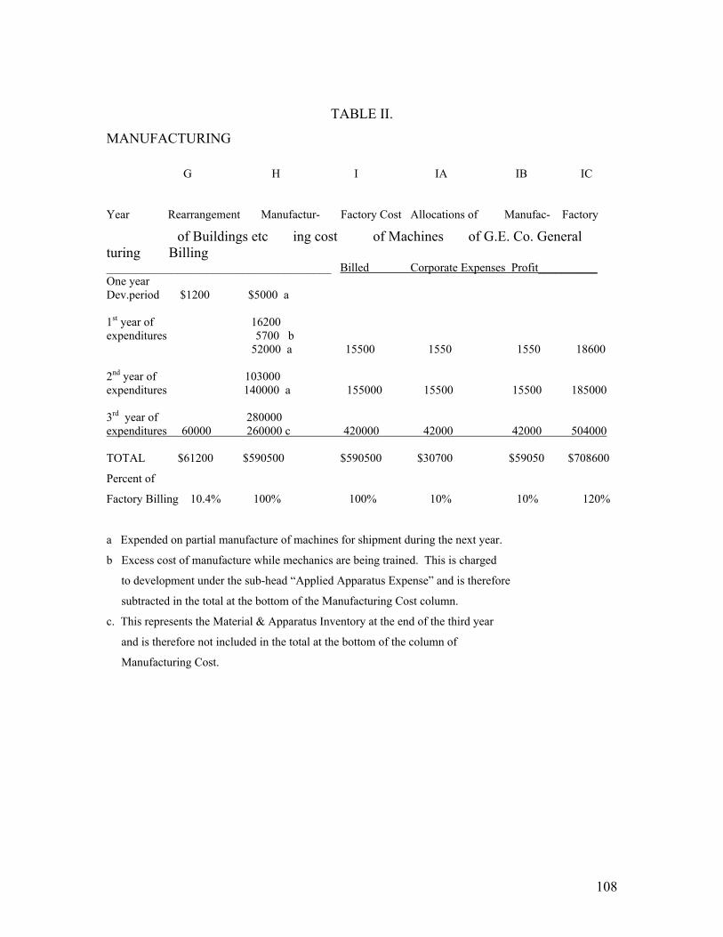
108
TABLE II.
MANUFACTURING
G H I IA IB IC
Year Rearrangement Manufactur- Factory Cost Allocations of Manufac- Factory
of Buildings etc ing cost of Machines of G.E. Co. General turing Billing ______________________________________ Billed Corporate Expenses Profit__________ One year Dev.period $1200 $5000 a 1st year of 16200 expenditures 5700 b 52000 a 15500 1550 1550 18600 2nd year of 103000 expenditures 140000 a 155000 15500 15500 185000 3rd year of 280000 expenditures 60000 260000 c 420000 42000 42000 504000 TOTAL $61200 $590500 $590500 $30700 $59050 $708600
Percent of
Factory Billing 10.4% 100% 100% 10% 10% 120%
a Expended on partial manufacture of machines for shipment during the next year.
b Excess cost of manufacture while mechanics are being trained. This is charged
to development under the sub-head “Applied Apparatus Expense” and is therefore
subtracted in the total at the bottom of the Manufacturing Cost column.
c. This represents the Material & Apparatus Inventory at the end of the third year
and is therefore not included in the total at the bottom of the column of
Manufacturing Cost.
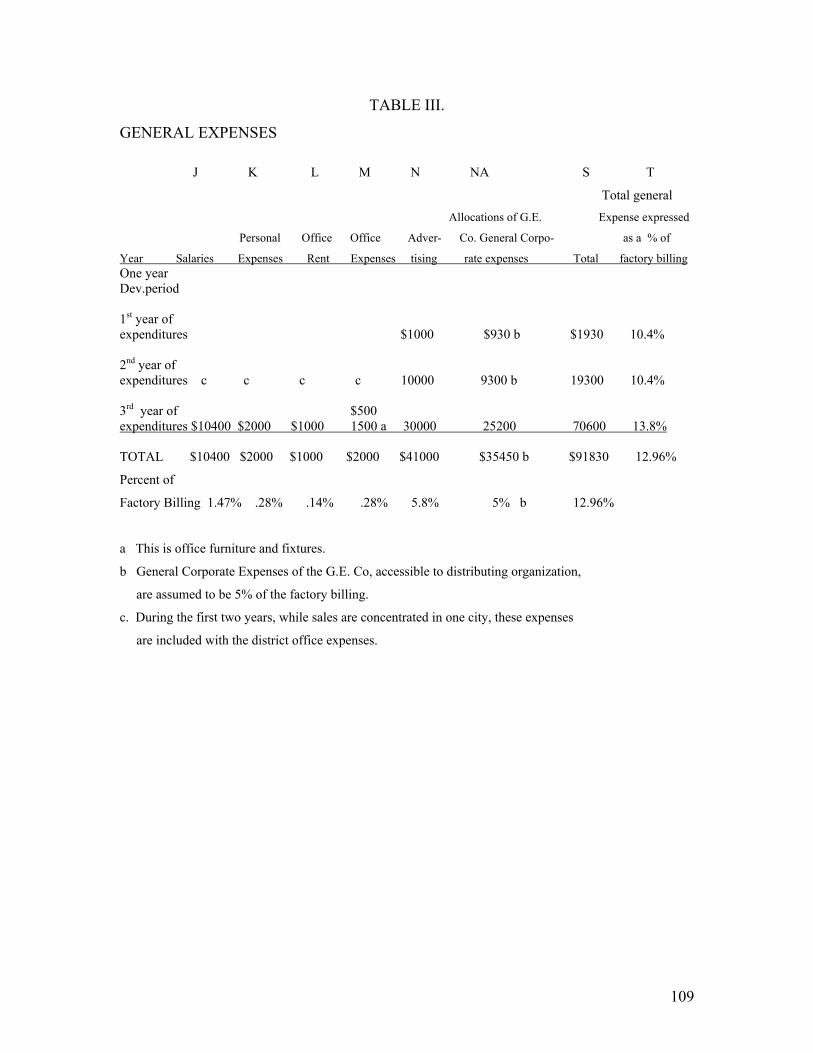
109
TABLE III.
GENERAL EXPENSES
J K L M N NA S T
Total general Allocations of G.E. Expense expressed
Personal Office Office Adver- Co. General Corpo- as a % of
Year Salaries Expenses Rent Expenses tising rate expenses Total factory billing One year Dev.period 1st year of expenditures $1000 $930 b $1930 10.4% 2nd year of expenditures c c c c 10000 9300 b 19300 10.4% 3rd year of $500 expenditures $10400 $2000 $1000 1500 a 30000 25200 70600 13.8% TOTAL $10400 $2000 $1000 $2000 $41000 $35450 b $91830 12.96%
Percent of
Factory Billing 1.47% .28% .14% .28% 5.8% 5% b 12.96%
a This is office furniture and fixtures.
b General Corporate Expenses of the G.E. Co, accessible to distributing organization,
are assumed to be 5% of the factory billing.
c. During the first two years, while sales are concentrated in one city, these expenses
are included with the district office expenses.

110
TABLE IV.
DISTRICT SALES EXPENSES
U V W X Z AA BB CC Personal Office Office Instal- % of Sales
Year Salaries Expenses Rent Expenses lation Service Total Billed One year Dev.period 1st year of $1000 expenditures $16400 $6000 $2000 $ 2000 a $6000 $600 $34000 67.2% 2nd year of 2000 expenditures 65400 26450 4000 1500 a 40000 2000 141350 28.7% 3rd year of 6000 expenditures 196200 79350 12000 7000 a 120000 6000 426550 31.0% TOTAL $278000 $111800 $18000 $19500 $166000 $8600 $601900 31.6%
Percent of
Factory Billing 1.4.64% 5.85% 0.94% 1.02% 8.7% 0.45% 31.0%
a Office furniture and fixtures purchased during the year

111
TABLE V.
SUMMARY
DD IC S E EE FF ? GG HH II Number of Expend. Profit Partial Liq. Accum.
Machines Factory General for or Refrig District Sales of Prev. Profit
Year Sold Billing Expense Devel Loss Boxes Expense Billed Devel. or Loss One year Dev.period $32500 b -32500 b 1st year of Loss expenditures 100 $18600 $1930 27250 b -13125 9000 34000 50405 -27250 b 13125 2nd year of expenditures 1000 186000 19300 32750 20850 80000 141350 480250 7725 ------- 3rd year of expenditures 3000 504000 70600 51000 114850 210000 426550 1377000 114850 ------- TOTAL 4100 $708600 $91830 $145500 d $122575 $299000 $601900 $1907555 $62825 d
13% a 20.3% a 15.2% e 15.7% c 31.6% e 8.9% a
a This is percentage of Factory Billing
b These items of development are not included in the sales price but are charged to the
development account
c This is percentage of sales billed. D
d The sum of the columns Expenditure for Development and Partial Liquiditation of Previous Develop-
ment is $205,824. The total development is this sum plus $25,722, the unliquidated development
at the end of the third year, or $232,047., which is 32.9% of the Factory Billing. E
e This is a percentage of the Gross Cost. The gross cost is the sum of column “I” and column “S”

112
TABLE VI.
SUMMARY
JJ KK Q O & P II LL MM NN
Factory Notes to Accum- # Avg. In- Profit Ex.
Inventory come due lated vestment as % of the
Unliq. Material Cash Goods in Transit Profit Lockup at Throughout Average
Year Develop. & Apparatus Balance & Accts. Rec. or Loss end of year the year Investment One year Dev.period $121047 a $5000 $125047 a $107297 a Less 1st year 148297 52000 $5000 $9950 $13025 228272 177159 -7.4% 2nd year 140572 140000 30000 95500 ----- 405072 317172 +6.0% 3rd year 25722 260000 80000 266000 ----- 631722 518897 +22.3% 1120525
Four years’ average investment $280131
Four years’ average profit 30644
Four years’ average profit 10.8%
a This includes $88547 previously expended for development of water cooled machine.
# This does not include the lockup in manufacturing equipment, catalogue tools, etc. It is
assumed that the G.E. Co’s 10% manufacturing profit will pay the interest on the investment
in manufacturing facilities.
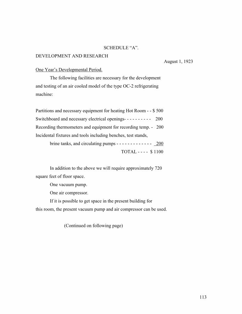
113
SCHEDULE “A”.
DEVELOPMENT AND RESEARCH August 1, 1923
One Year’s Developmental Period.
The following facilities are necessary for the development
and testing of an air cooled model of the type OC-2 refrigerating
machine:
Partitions and necessary equipment for heating Hot Room - - $ 500
Switchboard and necessary electrical openings- - - - - - - - - - 200
Recording thermometers and equipment for recording temp. - 200
Incidental fixtures and tools including benches, test stands,
brine tanks, and circulating pumps - - - - - - - - - - - - - 200
TOTAL - - - - $ 1100
In addition to the above we will require approximately 720
square feet of floor space.
One vacuum pump.
One air compressor.
If it is possible to get space in the present building for
this room, the present vacuum pump and air compressor can be used.
(Continued on following page)
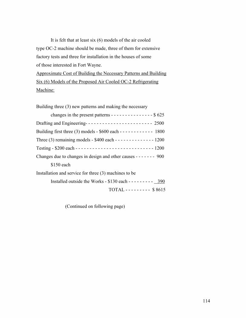
114
It is felt that at least six (6) models of the air cooled
type OC-2 machine should be made, three of them for extensive
factory tests and three for installation in the houses of some
of those interested in Fort Wayne.
Approximate Cost of Building the Necessary Patterns and Building
Six (6) Models of the Proposed Air Cooled OC-2 Refrigerating
Machine:
Building three (3) new patterns and making the necessary
changes in the present patterns - - - - - - - - - - - - - - - $ 625
Drafting and Engineering- - - - - - - - - - - - - - - - - - - - - - - - 2500
Building first three (3) models - $600 each - - - - - - - - - - - - 1800
Three (3) remaining models - $400 each - - - - - - - - - - - - - - 1200
Testing - $200 each - - - - - - - - - - - - - - - - - - - - - - - - - - - - 1200
Changes due to changes in design and other causes - - - - - - - 900
$150 each
Installation and service for three (3) machines to be
Installed outside the Works - $130 each - - - - - - - - - 390
TOTAL - - - - - - - - - $ 8615
(Continued on following page)
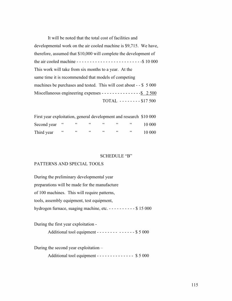
115
It will be noted that the total cost of facilities and
developmental work on the air cooled machine is $9,715. We have,
therefore, assumed that $10,000 will complete the development of
the air cooled machine - - - - - - - - - - - - - - - - - - - - - - - - -$ 10 000
This work will take from six months to a year. At the
same time it is recommended that models of competing
machines be purchases and tested. This will cost about - - $ 5 000
Miscellaneous engineering expenses - - - - - - - - - - - - - - -$ 2 500
TOTAL - - - - - - - - $17 500
First year exploitation, general development and research $10 000
Second year “ “ “ “ “ “ 10 000
Third year “ “ “ “ “ “ 10 000
SCHEDULE “B”
PATTERNS AND SPECIAL TOOLS
During the preliminary developmental year
preparations will be made for the manufacture
of 100 machines. This will require patterns,
tools, assembly equipment, test equipment,
hydrogen furnace, suaging machine, etc. - - - - - - - - - - $ 15 000
During the first year exploitation -
Additional tool equipment - - - - - - - - - - - - - - $ 5 000
During the second year exploitation –
Additional tool equipment - - - - - - - - - - - - - - $ 5 000
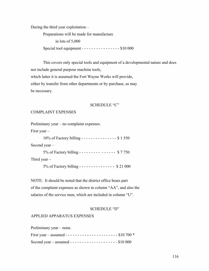
116
During the third year exploitation –
Preparations will be made for manufacture
in lots of 5,000
Special tool equipment - - - - - - - - - - - - - - - - $10 000
This covers only special tools and equipment of a developmental nature and does
not include general purpose machine tools,
which latter it is assumed the Fort Wayne Works will provide,
either by transfer from other departments or by purchase, as may
be necessary.
SCHEDULE “C”
COMPLAINT EXPENSES
Preliminary year – no complaint expenses.
First year –
10% of Factory billing - - - - - - - - - - - - - - - $ 1 550
Second year –
5% of Factory billing - - - - - - - - - - - - - - - $ 7 750
Third year –
5% of Factory billing - - - - - - - - - - - - - - - $ 21 000
NOTE: It should be noted that the district office bears part
of the complaint expenses as shown in column “AA”, and also the
salaries of the service men, which are included in column “U”.
SCHEDULE “D”
APPLIED APPARATUS EXPENSES
Preliminary year – none.
First year – assumed - - - - - - - - - - - - - - - - - - - - - - $10 700 *
Second year – assumed - - - - - - - - - - - - - - - - - - - - $10 000

117
Third year – assumed - - - - - - - - - - - - - - - - - - - - - $10 000
* This includes $5,700 which is the difference between the
actual factory cost of the first 100 machines and the amount
billed by the factory.
SCHEDULE “E”
TOTAL FOR YEAR
This column is the sum of columns “A”, “B”, “C”, and “D”.
SCHEDULE “F”
PER CENT OF FACTORY BILLING This column is the quotient of column “E” divided by
Column “IC”, expressed as a percentage.
SCHEDULE “G”
REARRANGEMENT OF BUILDINGS, ETC.
During the year of preliminary development it will be
necessary to rearrange the present Ice Machine department of
the Fort Wayne Factory. This will consist of rearranging the
machinery, the wiring, and constructing a partition.
TOTAL COST - - - - - $ 1, 200
NOTE: The ice machine department at the Fort Wayne Works now
occupies the first floor and basement of Building 12, which given
available manufacturing space of 14,400 square feet. The pattern
shop and pattern storage occupies the second and third floors of
this building, equaling 19,200 square feet.
The present space is sufficient for the manufacture of the
Audiffren machines and 100 domestic machines per year, and a
slight rearrangement will provide sufficient space for 1000

118
domestic machines required in the second year.
For the 3000 domestic machines required in the third year
and the Audiffren production there will be required a total of
34,000 square feet, which is practically the total area f
Building 12.
This will necessitate providing approximately 20,000 square
feet additional for pattern shop and pattern storage. The cost
of this extra 20,000 square feet will probably by $60,000.
(Continued on following page)

119
It should especially be noted that the interest on buildings,
catalogue tools, etc., it is not included in the accounts shown in
the following tables, because it is assumed that the Fort Wayne
factory will include this interest charge in the cost at which
the machines are billed.
Column “G” was included merely by way of mentioning these
items, for fear it should be supposed that they had been entirely
overlooked.
SCHEDULE “GG”
SALES BILLED The sales billed is taken from Table I of Part II of Report #2,
page 4, after deducting a 15% discount for the central station as
explained in schedule “Y”.
SCHEDULE “HH”
LIQUIDATION OF PREVIOUS DEVELOPMENT During the preliminary year the development acct. increased $ 32 500.
During the first year the development account increased $ 27 250.
During the second year the whole accumulated profit of $ 7,725
was used to liquidate some of the previous development.
During the third year the whole of the accumulated profit,
$114,850, was used to liquidate most of the remaining
development account. (See schedule “JJ”)
SCHEDULE “II”
ACCUMULATED PROFIT OR LOSS In this column is shown the loss of $13,125 during the first year. In the second year there was no accumulated profit, because the surplus profits were all used to liquidate development.

120
In the third year, there was no accumulated profit, because the surplus profits were all used to liquidate development.
SCHEDULE “H”
MANUFACTURING COST
During the year of preliminary development work was started
on a lot of 100 machines at an estimated cost of $200 each.
Preliminary year –
At the end of the year this work was 25%
completed. Expenditure - - - - - $5 000
First year –
During the first year of exploitation this
lot of 100 machines was completed. Expenditures - - $15 000
Extra Contingencies - - - - - 1 200
This made a total cost for the 100 machines of - $21 200
The machines were billed by the factory at - $15 500
Difference - - - - $ 5 700 *
* Four years’ average profit This difference was charged to the development
account under the heading “Applied App. Expend.”
Toward the end of the year work was one-third completed
on a lot of 1000 machines at an estimated
cost of $155 each - - - - - $52 000
Second Year –
Lot of 1000 machines completed - - - $103 000

121
One-third completion of a lot of 3000 machines
at $140 each - - - - - - $140 000
Third year –
Completion of lot of 3000 machines - - - $280 000
One-third completion of a lot of 6000 machines
at $150 each - - - - - - $260 000
(Continued on following page)

122
NOTE: Boxing of these machines would cost between $2.00 and $3.00
each, and it is assumed that this is included in the cost at which
the machines are billed.
The Fort Wayne factory have estimated that with rapid production
the type OC-2 air cooled machine can be made in lots of
100 as follows:
MATERIAL - - - - $ 86.74
LABOR - - - - 28.16
140% EXPENSE - - - 39.42
Total - $154.32
Of this cost $8.86 is the motor, and $28.26 is the automatic
control.
It will be noted that during the first year it has been
assumed that a lot of 100 machines would actually cost about $200
each. During the second year a lot of 1000 machines would actually
cost about $155 each. During the third year a lot of 3000 machines
would actually cost $140 each. And during the fourth year a lot of
6000 machines would actually cost $130 each.
SCHEDULE “I”
FACTORY COST OF MACHINES BILLED
Preliminary year – None.
First year - 100 machines at $155. - - - - $ 15 500
Second year - 1000 machines at $155. - - - - $155 000
Third year - 3000 machines at $140. - - - - $420 000

123
SCHEDULE “IA”
ALLOCATION OF GENERAL ELECTRIC COMPANY’S CORPORATE EXPENSES.
It is assumed that part of the general corporate expenses of
the General Electric Company will be assessed against the manufacture
of these machines. Since the commercial overhead on apparatus
shipped to the Western Electric Company is only 9%, we believe that
we are justified in assuming this allocation of expenses to the
Ice Machine Department of the Fort Wayne Works will not be more
than 10% of the factory cost.
SCHEDULE “IB”
MANUFACTURING PROFIT.
If a separate subsidiary company is organized to sell the
domestic refrigerating machines, it would be necessary for the
General Electric Company to take a manufacturing profit. So many
contracts are done on a “cost plus 10%” basis, that we have assumed
a 10% manufacturing profit would make a suitable return on the
investment in factory buildings, catalogues tools, etc.
SCHEDULE “IC”
FACTORY BILLING
This is the sum of columns “I”, “IA”, “IB”, and “IC”.
Preliminary year – None.
First year - 100 machines at $186. - - - $ 18 600
Second year - 1000 machines at $186. - - - $186 000
Third year - 3000 machines at $168. - - - $504 000
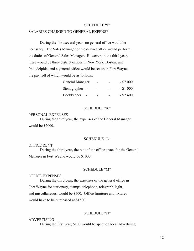
124
SCHEDULE “J”
SALARIES CHARGED TO GENERAL EXPENSE
During the first several years no general office would be
necessary. The Sales Manager of the district office would perform
the duties of General Sales Manager. However, in the third year,
there would be three district offices in New York, Boston, and
Philadelphia, and a general office would be set up in Fort Wayne,
the pay roll of which would be as follows:
General Manager - - - $7 000
Stenographer - - - - $1 000
Bookkeeper - - - - $2 400
SCHEDULE “K”
PERSONAL EXPENSES During the third year, the expenses of the General Manager
would be $2000.
SCHEDULE “L”
OFFICE RENT During the third year, the rent of the office space for the General
Manager in Fort Wayne would be $1000.
SCHEDULE “M”
OFFICE EXPENSES During the third year, the expenses of the general office in
Fort Wayne for stationary, stamps, telephone, telegraph, light,
and miscellaneous, would be $500. Office furniture and fixtures
would have to be purchased at $1500.
SCHEDULE “N”
ADVERTISING During the first year, $100 would be spent on local advertising

125
in New York. During the second year, $10,000 would be spent
on local advertising in New York. During the third year, $10,000
would be spent in each of the three cities, New York, Boston, and
Philadelphia.
SCHEDULE “NA”
ALLOCATION OF GENERAL ELECTRIC COMPANY’S GENERAL CORPORATE
EXPENSES CHARGED TO SEPARATE SUBSIDIARY COMPANY OR DEPART-
______________________MENTAL ORGANIZATION______________________
Since some of the General Electric corporate expenses have
already been included in Schedule “IA” where an allotment equal to
10% of the manufacturing cost was charged to the Ice Machine Department
of the Fort Wayne Works, it is assumed that the selling organization
will not be charged with allocations of the General Electric
Company’s general corporate expenses, amounting to more than
5% of the factory billing.
SCHEDULE “O”
GOODS IN TRANSIT AND
IN THE WAREHOUSE
First year – 100 machines each in transit and in warehouse
30 days - - 8 1/3 machines in transit at the same
time, valued at $186. each.
Total average value of goods in transit and in
the warehouse throughout the year - - - - - - - $ 1 550
Second year – 1000 machines each in transit and in warehouse
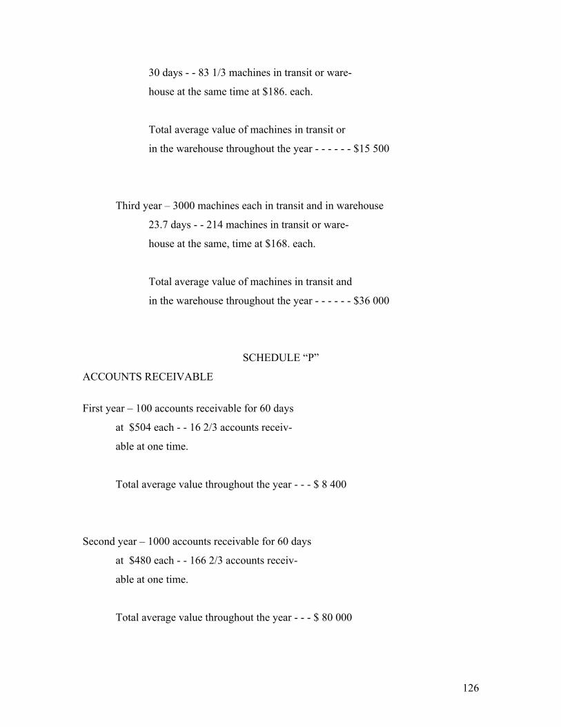
126
30 days - - 83 1/3 machines in transit or ware-
house at the same time at $186. each.
Total average value of machines in transit or
in the warehouse throughout the year - - - - - - $15 500
Third year – 3000 machines each in transit and in warehouse
23.7 days - - 214 machines in transit or ware-
house at the same, time at $168. each.
Total average value of machines in transit and
in the warehouse throughout the year - - - - - - $36 000
SCHEDULE “P”
ACCOUNTS RECEIVABLE
First year – 100 accounts receivable for 60 days
at $504 each - - 16 2/3 accounts receiv-
able at one time.
Total average value throughout the year - - - $ 8 400
Second year – 1000 accounts receivable for 60 days
at $480 each - - 166 2/3 accounts receiv-
able at one time.
Total average value throughout the year - - - $ 80 000

127
Third year – 3000 accounts receivable for 60 days
at $459 each - - 500 accounts receivable
at one time.
Total average value throughout the year - - - $230 000
SCHEDULE “Q”
CASH BALANCE First year – Since the sales billed are $50,405 it would
be reasonable to carry a cash balance of - - $ 5 000
Second year – Sales billed - - - - - - - - - - - - - - - - - - - - - - $480 250
assumed cash balance- - - - - - - - - - - - - - - $ 30 000
Third year – Sales billed - - - - - - - - - - - - - - - - - - - - - - - -$1 377 000
assumed cash balance- - - - - - - - - - - - - - - -$ 80 000
SCHEDULE “R”
UNLIQUIDATED DEVELOPMENT Column “T” is column “S” expressed as a percentage of
column “IC”.
SCHEDULE “U”
DISTRICT OFFICE SALARIES
First year – one district manager - - - - $ 5 000
two salesmen at $4 000- - - - 8 000
one bookkeeper- - - - - 2 400
one stenographer- - - - - 1 000
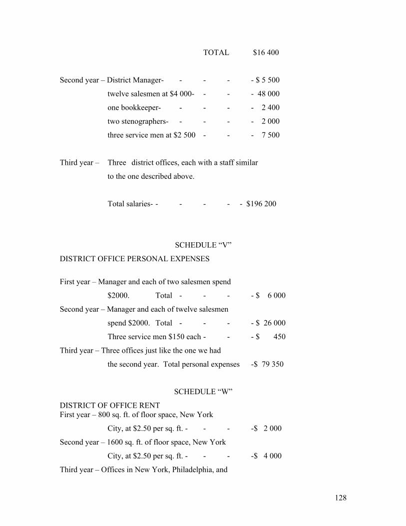
128
TOTAL $16 400
Second year – District Manager- - - - - $ 5 500
twelve salesmen at $4 000- - - - 48 000
one bookkeeper- - - - - 2 400
two stenographers- - - - - 2 000
three service men at $2 500 - - - 7 500
Third year – Three district offices, each with a staff similar
to the one described above.
Total salaries- - - - - - $196 200
SCHEDULE “V”
DISTRICT OFFICE PERSONAL EXPENSES
First year – Manager and each of two salesmen spend
$2000. Total - - - - $ 6 000
Second year – Manager and each of twelve salesmen
spend $2000. Total - - - - $ 26 000
Three service men $150 each - - - $ 450
Third year – Three offices just like the one we had
the second year. Total personal expenses -$ 79 350
SCHEDULE “W”
DISTRICT OF OFFICE RENT First year – 800 sq. ft. of floor space, New York
City, at $2.50 per sq. ft. - - - -$ 2 000
Second year – 1600 sq. ft. of floor space, New York
City, at $2.50 per sq. ft. - - - -$ 4 000
Third year – Offices in New York, Philadelphia, and
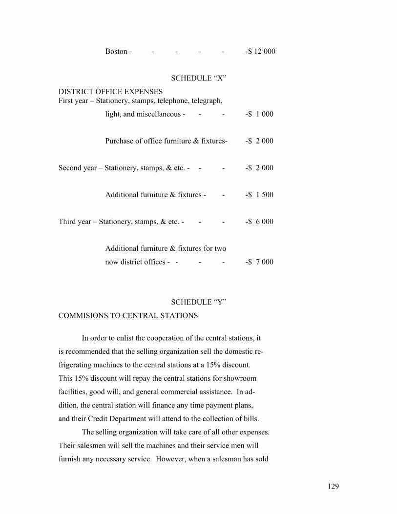
129
Boston - - - - - -$ 12 000
SCHEDULE “X”
DISTRICT OFFICE EXPENSES First year – Stationery, stamps, telephone, telegraph,
light, and miscellaneous - - - -$ 1 000
Purchase of office furniture & fixtures- -$ 2 000
Second year – Stationery, stamps, & etc. - - - -$ 2 000
Additional furniture & fixtures - - -$ 1 500
Third year – Stationery, stamps, & etc. - - - -$ 6 000
Additional furniture & fixtures for two
now district offices - - - - -$ 7 000
SCHEDULE “Y”
COMMISIONS TO CENTRAL STATIONS
In order to enlist the cooperation of the central stations, it
is recommended that the selling organization sell the domestic re-
frigerating machines to the central stations at a 15% discount.
This 15% discount will repay the central stations for showroom
facilities, good will, and general commercial assistance. In ad-
dition, the central station will finance any time payment plans,
and their Credit Department will attend to the collection of bills.
The selling organization will take care of all other expenses.
Their salesmen will sell the machines and their service men will
furnish any necessary service. However, when a salesman has sold
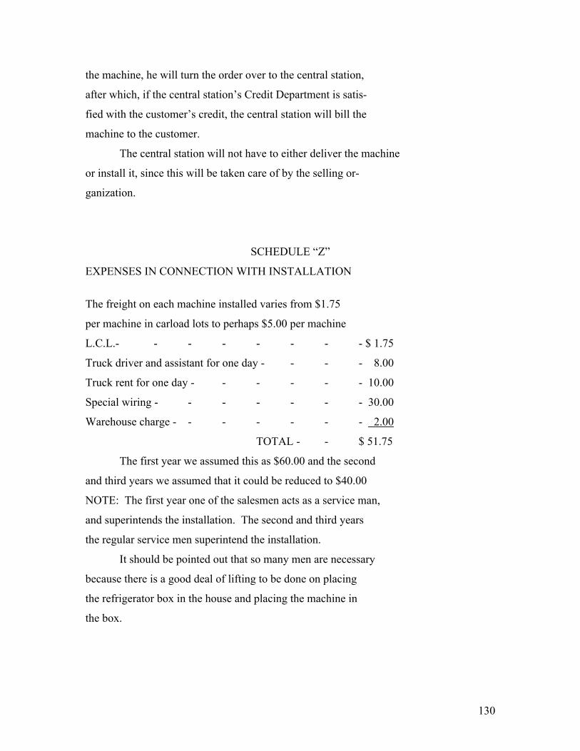
130
the machine, he will turn the order over to the central station,
after which, if the central station’s Credit Department is satis-
fied with the customer’s credit, the central station will bill the
machine to the customer.
The central station will not have to either deliver the machine
or install it, since this will be taken care of by the selling or-
ganization.
SCHEDULE “Z”
EXPENSES IN CONNECTION WITH INSTALLATION
The freight on each machine installed varies from $1.75
per machine in carload lots to perhaps $5.00 per machine
L.C.L.- - - - - - - - $ 1.75
Truck driver and assistant for one day - - - - 8.00
Truck rent for one day - - - - - - 10.00
Special wiring - - - - - - - 30.00
Warehouse charge - - - - - - - 2.00
TOTAL - - $ 51.75
The first year we assumed this as $60.00 and the second
and third years we assumed that it could be reduced to $40.00
NOTE: The first year one of the salesmen acts as a service man,
and superintends the installation. The second and third years
the regular service men superintend the installation.
It should be pointed out that so many men are necessary
because there is a good deal of lifting to be done on placing
the refrigerator box in the house and placing the machine in
the box.

131
SCHEDULE “AA”
SERVICE
First year – If 10 machines were shipped back to factory
the replacing of them would cost the district
office at least $60 each, in addition to the
service man’s pay, which is included under
Salaries, equals - - - - - $ 600
Second year – Fifty machines shipped back to factory, re-
placement cost at $40 each equals - - - $2 000
Third year – One hundred fifty machines shipped back to
factory, replacement cost equals - - - $6 000
SCHEDULE “BB”
TOTAL Column “BB” is the sum of “U”, “V”, “W”, “X”, “Z”, and “AA”.
SCHEDULE “CC”
PERCENT OF SALES BILLED Column “CC” is column “BB” expressed as a percentage of column “GG”
SCHEDULE “DD”
NUMBER OF MACHINES SHIPPED The number of machines shipped is taken from Table in Part II
of report II, page 4.
SCHEDULE “EE”
PROFIT OR LOSS This is obtained by subtracting columns “I”, “S”, “E”, “FF”,

132
“BB”, from column “GG”, with the exception that during the first year column “E” is charged to the development account.
SCHEDULE “FF” REFRIGERATOR BOXES First year – 100 boxes at $90 - - - - - $ 9 000
Second year – 1000 `` `` $80 - - - - - $ 80 000
Third year – 3000 `` `` $70 - - - - - $210 000
SCHEDULE “JJ”
UNLIQUIDATED DEVELOPMENT Previous development on water cooled machine - - - $ 88 547
Expenditures during preliminary year - - - - 32 500
Total at beginning of first year’s exploitation - - - $ 121 297
Additional development during first year - - - - 27 250
Total at beginning of second year - - - - $ 148 297
During the second year $27,528 was spent on development,
but this was all charged to sales.
Previous development liquidated by surplus profits - - - $ 7 725
Balance at beginning of third year - - - - $140 572
During the third year there was spent for development
$51,000, but this was all charged against sales.
Liquidated from profits - - - - - - $114 850
Development at beginning of fourth year - - - - $ 25 722
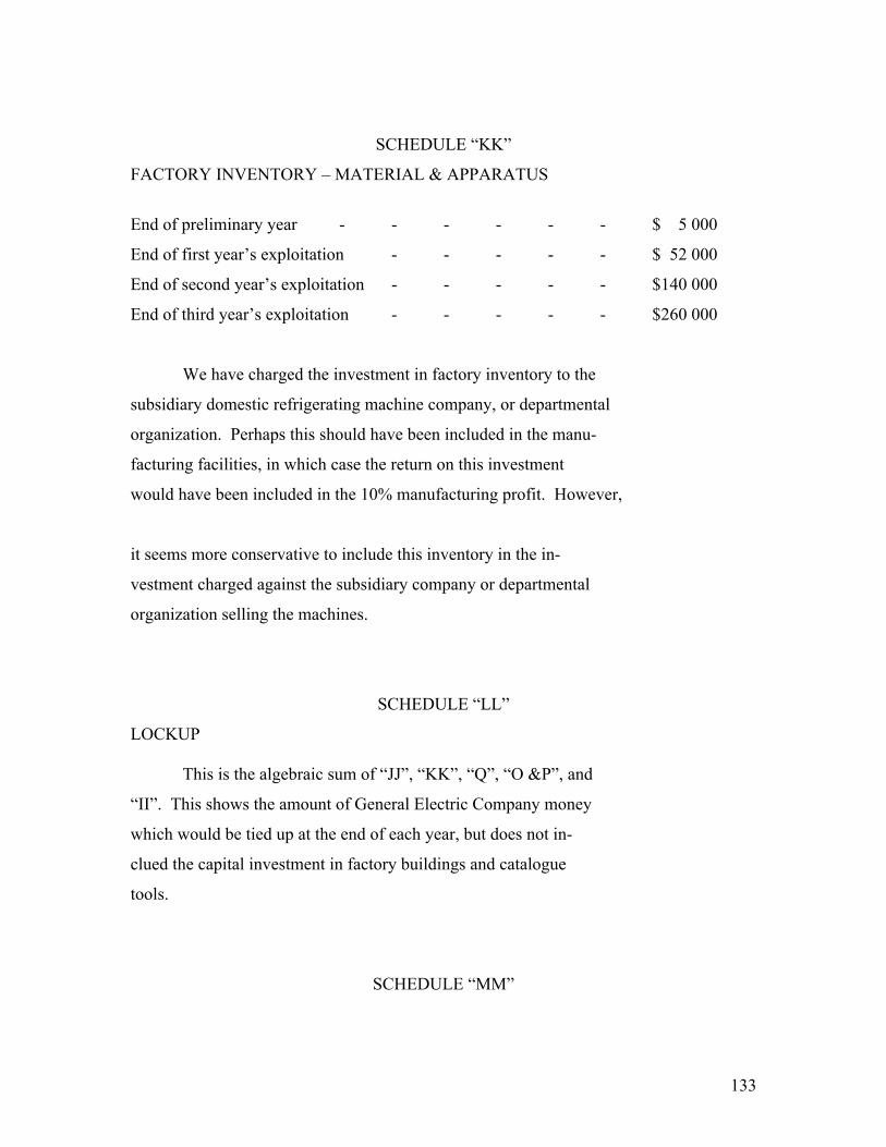
133
SCHEDULE “KK”
FACTORY INVENTORY – MATERIAL & APPARATUS
End of preliminary year - - - - - - $ 5 000
End of first year’s exploitation - - - - - $ 52 000
End of second year’s exploitation - - - - - $140 000
End of third year’s exploitation - - - - - $260 000
We have charged the investment in factory inventory to the
subsidiary domestic refrigerating machine company, or departmental
organization. Perhaps this should have been included in the manu-
facturing facilities, in which case the return on this investment
would have been included in the 10% manufacturing profit. However,
it seems more conservative to include this inventory in the in-
vestment charged against the subsidiary company or departmental
organization selling the machines.
SCHEDULE “LL”
LOCKUP This is the algebraic sum of “JJ”, “KK”, “Q”, “O &P”, and
“II”. This shows the amount of General Electric Company money
which would be tied up at the end of each year, but does not in-
clued the capital investment in factory buildings and catalogue
tools.
SCHEDULE “MM”

134
AVERAGE INVESTMENT THROUGHOUT THE YEAR
At the beginning of one years developmental
period the investment consisted merely in the amount
previously expended for development, namely - - - - $ 88 547
At the end of one year’s developmental period, the
lockup had increased to - - - - - - - $126 047
The average lockup throughout the one year’s development
period was - - - - - - - - - $107 297
One year’s exploitation:
At the beginning, the lockup was - - - - - - $126 047
At the end of the year, the lockup was - - - - - $228 272
Average lockup throughout the year - - - - - - $177 159
Second year’s exploitation:
At the beginning, the lockup was - - - - - - $228 272
At the end of the year, the lockup was - - - - - $406 072
Average lockup throughout the year - - - - - - $317 172
Third year’s exploitation:
At the beginning, the lockup was - - - - - - $406 072
At the end of the year, the lockup was - - - - - $631 722
Average lockup throughout the year - - - - - - $518 897
Average lockup throughout the four years - - - - - $280 131
Distributing the total profits through the four years given in

135
annual average profit of $30,644. Therefore, the average investment
throughout one year’s developmental period and three years’
exploitation would be $280,131, and the average return during
these four years would be 10.8% per annum.
SCHEDULE “NN”
PROFIT EXPRESSED AS A PERCENTAGE OF THE AVERAGE INVESTMENT
This is obtained by expressing column “EE”, table V, as a
percentage of column “MM”, table VI.
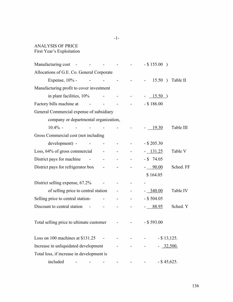
136
-1-
ANALYSIS OF PRICE First Year’s Exploitation
Manufacturing cost - - - - - - $ 155.00 )
Allocations of G.E. Co. General Corporate
Expense, 10% - - - - - - 15.50 ) Table II
Manufacturing profit to cover investment
in plant facilities, 10% - - - - 15.50 )
Factory bills machine at - - - - - $ 186.00
General Commercial expense of subsidiary
company or departmental organization,
10.4% - - - - - - - 19.30 Table III
Gross Commercial cost (not including
development) - - - - - - $ 205.30
Loss, 64% of gross commercial - - - - 131.25 Table V
District pays for machine - - - - - $ 74.05
District pays for refrigerator box - - - - 90.00 Sched. FF
$ 164.05
District selling expense, 67.2% - - - -
of selling price to central station - - - 340.00 Table IV
Selling price to central station - - - - - $ 504.05
Discount to central station - - - - - 88.95 Sched. Y
Total selling price to ultimate customer - - - $ 593.00
Loss on 100 machines at $131.25 - - - - - $ 13,125.
Increase in unliquidated development - - - - 32,500.
Total loss, if increase in development is
included - - - - - - - $ 45,625.

137
-2-
ANALYSIS OF PRICE
Second year’s exploitation.
Manufacturing cost - - - - - - $ 155.00 )
Allocations of G.E. Co. General Corporate
Expense, 10% - - - - - - 15.50 ) Table II
Manufacturing profit to cover investment
in plant facilities, 10% - - - - 15.50 )
Factory bills machine at - - - - - $ 186.00
General Commercial expense of subsidiary
company or departmental organization,
10.4% - - - - - - - 19.30 Table III
Gross Commercial cost (not including
development) - - - - - - $ 205.30
Profit, 10.2% of gross commercial - - - - 20.85 Table V
Development, 17.6% of factory billing - - - 32.75 Table I
District pays for machine - - - - - $ 258.90
District pays for refrigerator box - - - - 80.00 Sched. FF
$ 338.90
District selling expense, 28.7% of selling
price to central station - - - - 141.35 Table IV
Selling price to central station - - - - - $ 480.25
Discount to central station, 15% - - - - 84.75 Sched. Y
Total selling price to ultimate customer - - - $ 565.00
Profit on 1000 machines at $20.85 - - - - $ 20,850.
Liquidation of previous year’s loss - - - - 13,125.
$ 7,725.
Partial liquidation of previous development - - - 7,725.
Accumulated profit or loss - - - - - $ -------

138
-3-
ANALYSIS OF PRICE
Third Year’s Exploitation
Manufacturing cost - - - - - - $ 140.00 )
Allocations of G.E. Co. General Corporate
Expense, 10% - - - - - - 14.00 ) Table II
Manufacturing profit to cover investment
in plant facilities, 10% - - - - 14.00 )
Factory bills machine at - - - - - $ 168.00
General Commercial expense of subsidiary
company or departmental organization,
13.8% - - - - - - - 23.53 Table III
Gross Commercial cost (not including
development) - - - - - - $ 191.53
Profit, 20% of gross commercial - - - - 38.28 Table V
Development, 10.1% of factory billing - - - 17.00 Table I
District pays for machine - - - - - $ 246.81
District pays for refrigerator box - - - - 70.00 Sched. FF
$ 316.81
District selling expense, 31% of selling
price to central station - - - - 142.19 Table IV
Selling price to central station - - - - - $ 459.00
Discount to central station, 15% - - - - 81.00 Sched. Y
Total selling price to ultimate customer - - - $ 540.00
Profit on 3000 machines at $38.28 - - - - -$114,850.
Partial liquidation of previous development - - - - 114,850.
Accumulated profit or loss - - - - - -$ --------
139
DOMESTIC REFRIGERATION
February 14, 1925.
SUPPLEMENT TO REPORT OF AUGUST 27, 1924, AND PRECEDING REPORTS
Compiled and written by Walter Goll. A.R. Stevenson, Jr. Concurred in
H. E. Crane Clark Orr R. Steck
James J. Wood

140
INDEX PAGE
Introduction 1
History 2
Description 3
Installation 4
Service 5
Reliability 6
Protection 7
Capacity and Economy 7
Energy Consumed 8
Development 9
Costs 9
Prices 10
Comparison with prices of
other machines 10
Program 11
Conclusion 12

141
REPORT ON TYPE OC-2 DOMESTIC REFRIGERATING MACHINE
AIR COOLED (Supplementary to Report of Aug. 27, 1924 and preceding reports).
The development of this machine has progressed to such a
point that it is now deemed proper to undertake the manufacture and sale
during the next six months of one hundred machines, in order that
valuable experience may be gained. The present design has many advan-
tages and some disadvantages as compared with other machine now on the
market, but as a whole we consider it a superior design. There are
only two features in this design concerning which we feel some uncer-
tainty. These are noise and insulation. The noise is somewhat greater
than that of an electric fan and considerably less than that of a
vacuum cleaner or an oil burner. Continued efforts are being made to
improve this feature. However, the woman in whose homes these machines
are installed do not consider the noise a serious objection. It com-
pares favorable in this respect with competing machines.
In some of the water cooled machines there were insulation
failures but additional insulation and winding space provided in a re-
design of the motor, together with an improved treatment of the coils,
will, we believe, satisfactorily solve this problem. Sufficient time
has not elapsed since these changes were adopted to demonstrate how
long this insulation will last but we have reason to anticipate a life
of ten years. At this point in our development it seems proper to
review briefly the facts upon which we base our recommendations.

142
-2-
HISTORY
The Audiffren machine has been built for about twenty-six
years past in France, and for a dozen years here at Fort Wayne Works.
This Fort Wayne production has shown a complaint expense of 2.6% of
factory cost for the past eight years. About 1917 the engineers under-
took to apply their many years experience with the Audiffren machine
to the development of a domestic device. After several years experi-
ment they produced the Type OC-2 machine, water cooled, and with the
motor totally enclosed within the machine housing. In the early part
of 1921 about twenty-five of these machines were installed in the homes
of G. E. employees at Fort Wayne and Schenectady. Very few of these
machines remain in service, most of them having been returned to the
factory, but the experience gained has been invaluable in perfecting
the design.
In August, 1923, work was started on the redesign for air
cooling. This change presented many new problems not thereto fore
encountered, which have been successfully solved. The present design
is the result of an intimate experience with machines and problems of
like character, antedating probably the experience of any other domestic
refrigerating company now in the market.
DESCRIPTION
This design consists of a split-phase motor mounted on the
shaft of a two-cylinder single acting compressor. These oscillating
cylinders, together with the eccentric which drives them, are of the
same general design as those which have performed so successfully in the
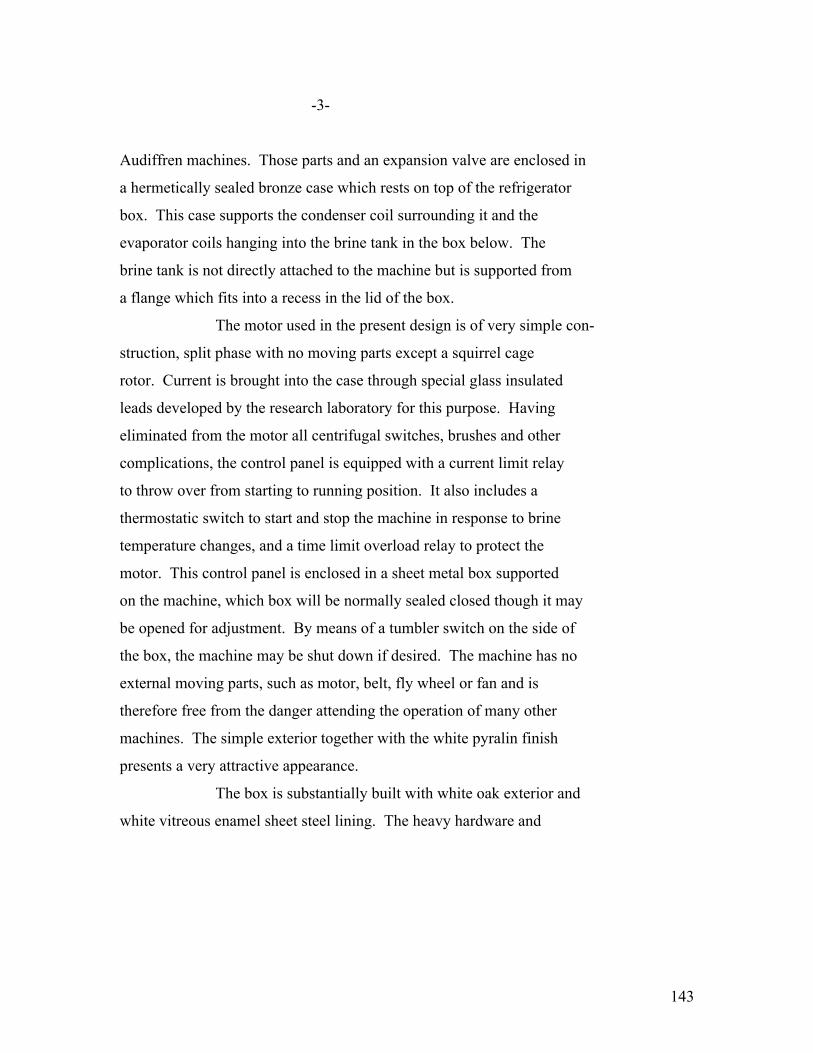
143
-3-
Audiffren machines. Those parts and an expansion valve are enclosed in
a hermetically sealed bronze case which rests on top of the refrigerator
box. This case supports the condenser coil surrounding it and the
evaporator coils hanging into the brine tank in the box below. The
brine tank is not directly attached to the machine but is supported from
a flange which fits into a recess in the lid of the box.
The motor used in the present design is of very simple con-
struction, split phase with no moving parts except a squirrel cage
rotor. Current is brought into the case through special glass insulated
leads developed by the research laboratory for this purpose. Having
eliminated from the motor all centrifugal switches, brushes and other
complications, the control panel is equipped with a current limit relay
to throw over from starting to running position. It also includes a
thermostatic switch to start and stop the machine in response to brine
temperature changes, and a time limit overload relay to protect the
motor. This control panel is enclosed in a sheet metal box supported
on the machine, which box will be normally sealed closed though it may
be opened for adjustment. By means of a tumbler switch on the side of
the box, the machine may be shut down if desired. The machine has no
external moving parts, such as motor, belt, fly wheel or fan and is
therefore free from the danger attending the operation of many other
machines. The simple exterior together with the white pyralin finish
presents a very attractive appearance.
The box is substantially built with white oak exterior and
white vitreous enamel sheet steel lining. The heavy hardware and
144
-4-
gaskets around the doors prevent leakage. The insulation consists of
two inches or cork. The outside dimensions of the box are,
Width 41”
Height 53”
Depth 25”
The total inside volume is approximately 14 cu. Ft. of which approximately
9 cubic feet is available for food storage. The steel brine tank is
finished in vitreous enamel and sufficient space is provided between it
and the box to permit of easy access for thorough cleaning. This box
in the quality and quantity of insulation, its sturdiness of construc-
tion and the ease with which it may be cleaned is superior to any other
box on the market. Special precautions have been taken to seal all the
interior woodwork, thus preventing musty odors frequently found in
other refrigerators. It is made to our designs by one of the largest
manufacturers in this line.
INSTALLATION
The outstanding advantage of this machine is that it will be
charged at the factory with gas and oil, sealed up and together with the
refrigerator box and brine tank, shipped in three parts ready for
installation. In one half hour two men can easily roll the box into
place, drop in the brine tank, fill it with brine and place the machine
on top of the box with the expansion coils hanging in the brine. To
start the machine it is then necessary only to connect into an outlet
or lamp socket. No adjustments nor tests will ordinarily be required
on the customers’ premises.
Contrast the simplicity and low cost of this installation with

145
-5-
the preliminary survey, piping and connecting required by many other
systems of domestic refrigeration
SERVICE
In case of complaint minor adjustments in our control
mechanism can be made on the customer’s premises.
The mechanism inside the main case is so simple and rugged
there is little likelihood of failure. In case of trouble, however the
machine would be replaced in about fifteen minutes work on the custo-
mer’s premises and taken to a service station or sent to the factory
for examination and repair. Since no major repairs would be attempted
on the customer’s premises, the service man would require only a little
knowledge of electrical control apparatus. It is said our competitors
can make repairs on the spot. They can service the motor, replace the
belt, oil some of the exposed bearings, tighten the stuffing box and
gas to replace what has leaked through stuffing box and pipe connec-
tions. It is our understanding, however, that major repairs, such as
replacement of valves, taking up bearings, etc. are made in a service
shop.
To remove one of those competing machines involves the open-
ing of the pipe lines, with loss of some gas, and the danger of getting
air and moisture into the system. Our own machine, being self-contained
is simply lifted our of the brine tank and the box without breaking
pipe connection. To facilitate this operation of insulation and
removal we have developed a convenient crane which can be collapsed
ready transportation. It is obvious that the kind of service our com-
petitors do on the spot will not be necessary with our machine with

146
-6-
possible exception of control adjustments. We had no belt to replace.
No external bearings to lubricate, no brushes, centrifugal switches, etc.
to adjust on the motor, and no danger of gas or oil leakage, since our
machine has no stuffing box and is hermetically sealed, all joints being
thoroughly soldered in the factory.
RELIABILITY
The above discussion under “SERVICE” enumerates the reasons for
our faith in the reliability of this machine, which can be summed up as
follows:-
All operating parts are completely sealed with a supply of
lubricant adequate for all time, and there is no stuffing box to
leak either gas or oil.
The motor is very simple, without brushes, short circuiting
switches or moving contacts.
The machine is charged and sealed at the factory under ideal
conditions for excluding moisture and air and does not require any piping
or gas connections on the customer’s premises.
The eccentric driven single-acting oscillating cylinder com-
pressor with snifter discharge valves, all essentially as used in the
Audiffren machine for so many years, is the simplest and most reliable form
of compressor of which we have knowledge.
The use of materials and methods of lubrication, peculiarly
adapted to this machine, developed by long experience with the Audiffren
and later designs.

147
-7-
PROTECTION
Patent approval on this design was obtained some time ago, and
the applications are pending covering certain details. However, the
broad ideas are old and we will have no valuable patent protection.
Nevertheless the experience gained in building the Audiffren machine and
in developing the domestic device constitutes a broad knowledge of the
art, which is highly essential to successful production, and which would
require considerable time and expense for others to acquire.
CAPACITY AND ECONOMY
The following data are compiled from careful tests made in
our own factory upon various machines.
Room Temp. 75°F Room Temp. 90°F
Economy Capacity Economy Capacity Watt-hr B.t.u. Watt-hr B.t.u. B.t.u. per hr. B.t.u. per hr.
OC-2 0.387 650 0.500 510
Odin 0.41 630 - -
Savage Arms 0.58 570 0.71 430
Kelvinator 1 Cyl. 0.835 370 0.90 350
Model #1420 “ 2 “ 0.515 685 - -
Frigidaire 2 “ 0.517 710 0.598 620
SerV-el 2 “ 0.374 928 0.484 739
These tests indicate performance of the machines alone on a
test brine tank and do not include the characteristics of the box. ? rate of
600 B.t.u. per hour is equivalent to the melting of 100 pounds of ice
in 24 hours.

148
-8-
This table indicates that our machine takes less power per
unit of refrigeration than any other, except the SerV-el, which is about 3% more
efficient at 75°F. room temperature. That is probably due to the
larger capacity of the SerV-el machine, it being a well known fact that
other things being equal the larger the machine the higher the efficency.
The power input on our machine is about 250 watts against 350 watts for
the SerV-el.
We have built one model of about the same size as the SerV-el
which showed an economy of .323 W. Hr. per B.t.u., which is about 14%
higher efficiency that the SerV-el.
We consider our machine is of a capacity best adapted to the box
we are furnishing, since it will maintain proper temperatures even on a
90°F. day with 11 hours operation in each 24 hours.
SerV-el is sold for use with boxes already in service, many
of which have poor insulating qualities and therefore require more
refrigeration.
ENERGY CONSUMED
Aside from the efficiency of the machine, the cost of opera-
tion is dependent upon the quality of the box and its resistance to the
leakage of heat. For this reason operating tests of different machines
are not comparable because of the wide variation in box efficiency.
Mr. T. I. Jones of the Brooklyn Edison Co. in a paper presented
before the Association of Edison Ill’g. Companies, Oct. 1922, gave an
annual current consumption of 800 K.W. hours for these machines, which
is at the rate of 2.19 K.W.H. per day the year around.
One of our machines with standard box in Mr. H. E. Crane’s
149
-9-
home consumed in actual operation an average of 2.6 K.W.H. per day for
sixty-hour days from July 25 to Sept. 28, 1924. This was a period of
unusually high temperature with several days of 93°F., or over. From
Sept. 28, 1924 to Feb. 12, 1925, a period of 137 days, the consumption
has averaged 2.36 K.W.Hr. per day. The average for the total 201 days
is 2.44 K.W.Hr. per day.
DEVELOPMENT
Applied apparatus expense expenditures totaled $54,217.00 up
to Dec. 31, 1924. The engineering budget submitted recently contained
an item of $46,110.00 A.A.E. for this work for 1925. This, of course,
is an estimate only. Future development will be directed along lines
indicated by experience with the present machine, and as dictated by the
trend of commercial requirements. Tools and patterns for various rates
of production must be provided at the estimated costs.
100 machines $8,000.
Additional for 1000 “ 5,000
“ “ 3000 “ 5,000
Total for - - - 3000 “ $18,000
COSTS
Estimates just completed show costs on the machine complete
including control panel and brine tank, but not including the box, as
follows:-
LOTS 100 1000 3000
Material 78 77.75 75.98 Direct Labor 60 29.67 26.64 Expense (150%) 90 (135%) 40.47 (120%) 31.97 220 147.47 134.59
On boxes we have a firm quotation of $115.00 in lots of 100 F.O.B. St. Paul, and estimate a price of $100,00 in lots of 1000 or 3000.
Realizing there are many methods of determining a price, we
Merely suggest the following items which might be included.
150
-10-
PRICES
BASED ON A PRODUCTION OF 3000 PER YEAR
Machine complete - - - - $ 135.00 A.A.E. 25% - - - - 33.75 Gross Factory Cost - - 168.75 Commercial Expense - 16 2/3% 28.12 196.87 Profit 20% - - 246.10
Crating 4.00 250.10 Refrigerator Box F.O.B. St. Paul 100.00 Handling charge 10% 10.00 Freight St. Paul to Ft. Wayne 1.92 Price to agent FOB Ft. Wayne 362.02 Discount to agent to cover freight, installation charge and profit 34% of $550.00 187.00 Selling price to customer - $ 549.00
This set up is made merely as a suggestion and will no doubt
be materially modified by any commercial organization undertaking the
sale of this device. However, it indicates that the total development
incurred up to this date can be liquidated in the sale of 3000 machines
a commercial selling expense provided for which is in all probability
more than ample for this class of appliances a satisfactory profit for
the G.E. Co. and a working discount or commission for the distributor.
COMPARISON WITH PRICES OF OTHER MACHINES
The following prices are delivered and installed, including box
Cu. Ft. Food Space Price
OC-2 9 $ 550.00 Frigidaire 9 605.00 SerV-el 9 550.00

151
-11-
Cu. Ft. Food Space Price Kelvinator) machine ) $340.00 installed ) Box brought ) retail equal ) 200.00 to ours ) 9 $540.00 PROGRAM
Our definite recommendation is to begin the manufacture as
soon as authority can be secured (not later that March 1st, 1925) of
100 machines and the purchase of 100 boxes, these equipments to be sold
in Fort Wayne and one other nearby city, preferably Cincinnati or
Cleveland, where sales and service efforts can be concentrated and
carried on at a minimum of expense. This will involve the purchase of
materials, the making of patterns and tools and the training of help.
If authority can be secured by March 1st, we can start assembly June
1st, at the rate of five per week, and complete assembly of 100 machines
by September 1st.
The sale and servicing of these first 100 machines can be
handled by the factory organization here at Fort Wayne with some slight
sales assistance from the local office. Following is an estimate of
the cost of this program.
152
-12-
100 refrigerating machines at $230.00 - $23,000. 100 refrigerator boxes, FOB St. Paul, Minn. - - - 115.00 - 11,500 Boxing refrigerator machines 500 Shop cost- boxed- - - - - - - $35,000.00 Freight on boxes - - - - - - - - - - - - - - - - 500. Freight on refrigerating machines- - - - - 200. Cartage and installation - - - - - - - - - - - 1,500. Sales expense, salaries, rental, show space and servicing six months Cincinnati or Cleveland 5,000. Selling and servicing Fort Wayne 1,000. Extra traveling expenses- - - - - - - - - - - 600. Local advertising and bulletin- - - - - - 1,000. Contingencies and complaints - - - - - 5,200.
Total sales and distribution expense - - - - - 15,000.00 Re-arrangement manufacturing facilities 2,000. Tools and patterns for 100 machines- - 8,000. 10,000.00 GRAND TOTAL $60,000.00 At a selling price of $550.00 this initial campaign would
show only a small loss and would give us a very valuable and neces-
sary experience.
Upon the completion of this program we will be in an
excellent position to go ahead with a production of 1000 machines in
1926 and further extensions in the future, provided the commercial
department has developed an adequate plan for the sale of this product.
CONCLUSION
Based upon many years experience in the manufacture of the
Audiffren and in the development of this domestic machine, supplemented
by tests on all the leading domestic machines now on the market, we are
convinced that the present machine is superior to any now on the market
153
-13-
While no doubt improvements will continue to be made in the
present design, we feel sure we should undertake immediately to exploit
this machine. To keep pace with the development in this new industry
on which so much time and money are being spent by our competitors, we
must continue our development work aggressively.
Ed note: supplement included 9 photos and drawings that were too dark to copy.
Original copies of the GE photos are in the GE Photo Collection at the
Schenectady Museum
GE photo# 283076 “OC-2, Form H Refrigerating Machine on Seeger #370 Special Refrigerator
GE photo# 283077 “OC-2, Form H Refrigerating Machine on Seeger #370 Special Refrigerator
GE photo# 283079 “OC-2, Form H Refrigerating Machine removed from Seeger #370 Special
Refrigerator, door open showing brine tank in place.
Drawing (no number or title) Ed note: shows crossection of OC-2 evaporator
Photo (no number or title) Ed note: shows open control box for OC-2
Photo (no number or title) Ed note: shows outside of control box for OC-2
Drawing (no number or title) Ed note: shows crossection of OC-2 compressor and condenser
Illustration (no number or title) Ed note: shows remotely installed Kelvinator system
Illustration (no number or title) Ed note: shows remotely installed Frigidaire system

154
APPENDIX #1 Editor’s Note: This is one page, faded so that it is virtually unreadable. It appears to be a table of data on the Audiffren machines from 1917 – 1921.
APPENDIX #2.
EXPENSES ALREADY INCURRED FOR DEVELOPMENT
********************
Schenectady, July 2, 1923. Mr. A. B. Stevenson, Jr., P & M Engineering Dept., B U I L D I N G. Attached is a detailed statement covering Applied
Apparatus Expenditures on Refrigeration Work done at the
Schenectady, Lynn, Pittsfield and Ft. Wayne Works since 1915.
This report indicates that the Company has spent since 1915
an aggregate of $138,733. for the development of domestic and
Audiffren machines. During this period, $99,149. of the
above development was written off: $13,873. was transferred
to the General Office, and $11,555. was credited to the
several accounts from credits received through shipments.
This has resulted in an unliquidated balance on June 1, 1923
of $14,156.
I believe the above gives you the information requested
in your recent letter.
Yours truly,
N.J. KINGSBURY.
For: A. W. Oppermann
AWO:W

155
-2-
RECAPITULATION OF APPLIED APPARATUS EXPENDITURES
TO JUNE, 1 1923 ON REFRIGERATION WORK (Does not include development on Audiffren machines.)
TOTAL EXPENDITURES Schenectady Works - - - $ 2,490. No work now being done. Lynn Works - - - - 15,945. “ “ “ “ Pittsfield Works - - - 832. “ “ “ “ Fort Wayne Works - - - 87,226 Work actively going on. _________ TOTAL EXPENDITURES $106,493 Written off or charged to residue - - - 99,149 _________ Unliquidated balance in Dev, a/c June 1, 1923 $ 7,344

156
-3-
DEVELOPMENT WORK ON REFRIGERATION
SCHENECTADY RESEARCH LABORATORY Year Research Laboratory 1915 $ 936. Written off in December, 1915. 1916 738. $540. written off in Dec. 1917 (Bal. Charged to residue) 1917 - - - 1918 - - - 1919 478. Charged to residue. 1920 318. “ “ “ ____________ TOTAL$ 2,490.
LYNN WORKS Year Debits Credits Written off Unliq. Balance ____ _____ ______ _________ Accumulative__ 1919 $ 3,025. - - - - - - - - $ 3,025. 1920 8,858. - - - - - - - - 11,883. 1921 4,062. - - - - - - - - - - - - - ______________ ______ _________ _____________ TOTAL $15,945. - - - $ 15,945. - - - -
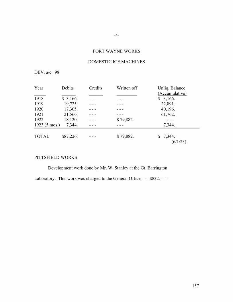
157
-4-
FORT WAYNE WORKS
DOMESTIC ICE MACHINES
DEV. a/c 98 Year Debits Credits Written off Unliq. Balance _____ ______ ______ _________ (Accumulative) 1918 $ 3,166. - - - - - - $ 3,166. 1919 19,725. - - - - - - 22,891. 1920 17,305. - - - - - - 40,196. 1921 21,566. - - - - - - 61,762. 1922 18,120. - - - $ 79,882. - - - 1923 (5 mos.) 7,344. - - - - - - 7,344. TOTAL $87,226. - - - $ 79,882. $ 7,344. (6/1/23) PITTSFIELD WORKS
Development work done by Mr. W. Stanley at the Gt. Barrington Laboratory. This work was charged to the General Office - - - $832. - - -
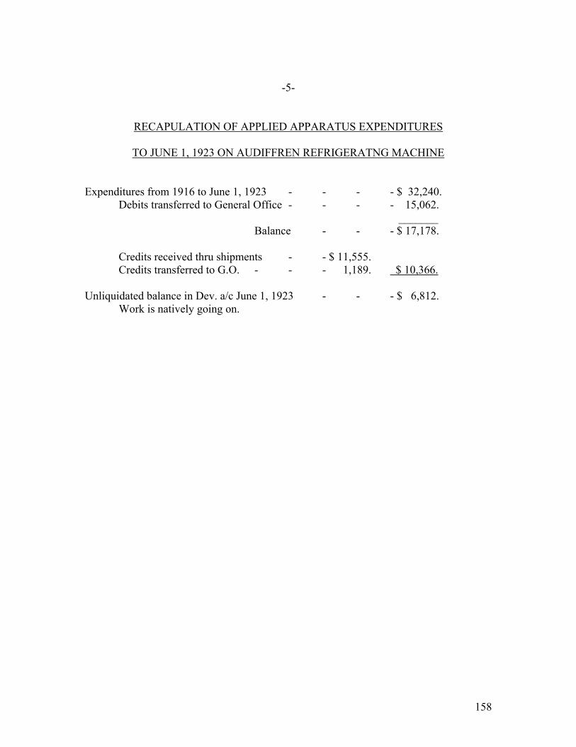
158
-5-
RECAPULATION OF APPLIED APPARATUS EXPENDITURES
TO JUNE 1, 1923 ON AUDIFFREN REFRIGERATNG MACHINE Expenditures from 1916 to June 1, 1923 - - - - $ 32,240. Debits transferred to General Office - - - - 15,062. _______ Balance - - - $ 17,178. Credits received thru shipments - - $ 11,555. Credits transferred to G.O. - - - 1,189. $ 10,366. Unliquidated balance in Dev. a/c June 1, 1923 - - - $ 6,812. Work is natively going on.
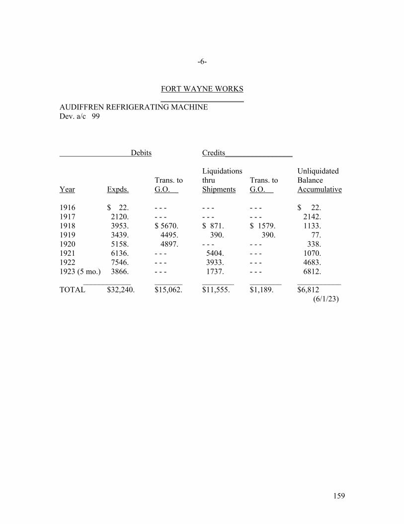
159
-6-
FORT WAYNE WORKS _____________________
AUDIFFREN REFRIGERATING MACHINE Dev. a/c 99 Debits Credits_________________ Liquidations Unliquidated Trans. to thru Trans. to Balance Year Expds. G.O. Shipments G.O. Accumulative 1916 $ 22. - - - - - - - - - $ 22. 1917 2120. - - - - - - - - - 2142. 1918 3953. $ 5670. $ 871. $ 1579. 1133. 1919 3439. 4495. 390. 390. 77. 1920 5158. 4897. - - - - - - 338. 1921 6136. - - - 5404. - - - 1070. 1922 7546. - - - 3933. - - - 4683. 1923 (5 mo.) 3866. - - - 1737. - - - 6812. ____________ _______ ________ ________ ___________ TOTAL $32,240. $15,062. $11,555. $1,189. $6,812 (6/1/23)
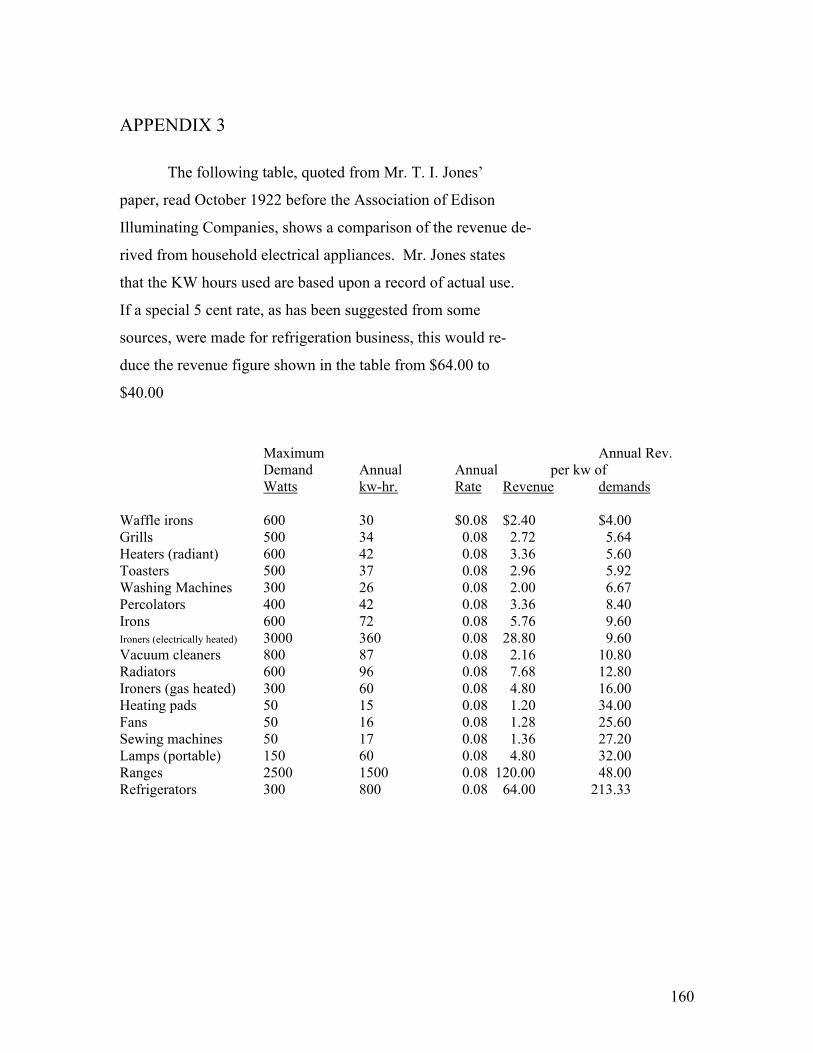
160
APPENDIX 3
The following table, quoted from Mr. T. I. Jones’
paper, read October 1922 before the Association of Edison
Illuminating Companies, shows a comparison of the revenue de-
rived from household electrical appliances. Mr. Jones states
that the KW hours used are based upon a record of actual use.
If a special 5 cent rate, as has been suggested from some
sources, were made for refrigeration business, this would re-
duce the revenue figure shown in the table from $64.00 to
$40.00
Maximum Annual Rev. Demand Annual Annual per kw of Watts kw-hr. Rate Revenue demands Waffle irons 600 30 $0.08 $2.40 $4.00 Grills 500 34 0.08 2.72 5.64 Heaters (radiant) 600 42 0.08 3.36 5.60 Toasters 500 37 0.08 2.96 5.92 Washing Machines 300 26 0.08 2.00 6.67 Percolators 400 42 0.08 3.36 8.40 Irons 600 72 0.08 5.76 9.60 Ironers (electrically heated) 3000 360 0.08 28.80 9.60 Vacuum cleaners 800 87 0.08 2.16 10.80 Radiators 600 96 0.08 7.68 12.80 Ironers (gas heated) 300 60 0.08 4.80 16.00 Heating pads 50 15 0.08 1.20 34.00 Fans 50 16 0.08 1.28 25.60 Sewing machines 50 17 0.08 1.36 27.20 Lamps (portable) 150 60 0.08 4.80 32.00 Ranges 2500 1500 0.08 120.00 48.00 Refrigerators 300 800 0.08 64.00 213.33

161
APPENDIX 4
TABLE COPIED FROM ICE & REFRIGERATION BLUE BOOK The consumption of ice in tons for commercial purposes by states is estimated at 35,305,000 tons. By the term commercial is meant ice sold to families, butchers, stores of various kinds, etc., and does not include ice used for cold storage purposes and ice manufactured by plants using it for their own purposes. The approximate amount consumed in each state from figures obtained from various sources, is shown in table XII. TABLE XII – Estimated Consumption Of Ice In Various States
State Annual Consumption (Tons)
Alabama 380,000 Arizona 245,000 Arkansas 500,000 California 1,500,000 Colorado 360,000 Connecticut 300,000 Delaware 150,000 Florida 650,000 Georgia 750,000 Idaho, Montana, NewMexico, Utah, and Wyoming 150,000 Illinois 3,500,000 Indiana 1,200,000 Iowa 450,000 Kansas 600,000 Kentucky 525,000 Louisiana 750,000 Maine 150,000 Maryland 625,000 Massachusetts 1,000,000 Michigan 600,000 Minnesota 400,000 Mississippi 250,000 Missouri 2,000,000 Nebraska 300,000 Nevada 50,000 New Hampshire 100,000 New Jersey 1,250,000 New York 5,000,000 North Carolina 385,000 The Dakotas 130,000 Ohio 2,000,000 Oklahoma 325,000
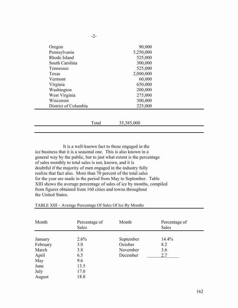
162
-2- Oregon 90,000 Pennsylvania 5,250,000 Rhode Island 525,000 South Carolina 300,000 Tennessee 525,000 Texas 2,000,000 Vermont 60,000 Virginia 650,000 Washington 200,000 West Virginia 275,000 Wisconsin 300,000 District of Columbia 225,000
Total 35,385,000 It is a well-known fact to those engaged in the ice business that it is a seasonal one. This is also known in a general way by the public, but to just what extent is the percentage of sales monthly to total sales is not, known, and it is doubtful if the majority of men engaged in the industry fully realize that fact also. More than 70 percent of the total sales for the year are made in the period from May to September. Table XIII shows the average percentage of sales of ice by months, compiled from figures obtained from 160 cities and towns throughout the United States. TABLE XIII – Average Percentage Of Sales Of Ice By Months Month Percentage of Month Percentage of Sales Sales January 2.6% September 14.4% February 3.0 October 8.2 March 3.8 November 3.6 April 6.5 December 2.7_____ May 9.6 June 13.5 July 17.0 August 18.8

163
TABLE SHOWING AVERAGE RETAIL PRICES CHARGED FOR ICE IN VARIOUS SECTIONS
OF THE UNITED STATES ************
Retail Price In Cents Per Hundredweight During Year District 1922 x 1923 o Eastern- - - - 59.1 cents 62.3 cents Midwestern - - - 59.2 60.7 Western - - - 73.5 83.0 Southern - - - 60.1 61.7 General Average - - 62.3 65.0 x from Ice & Refrigeration Blue Book o From page 451 May 1923 Ice and Refrigeration magazine.
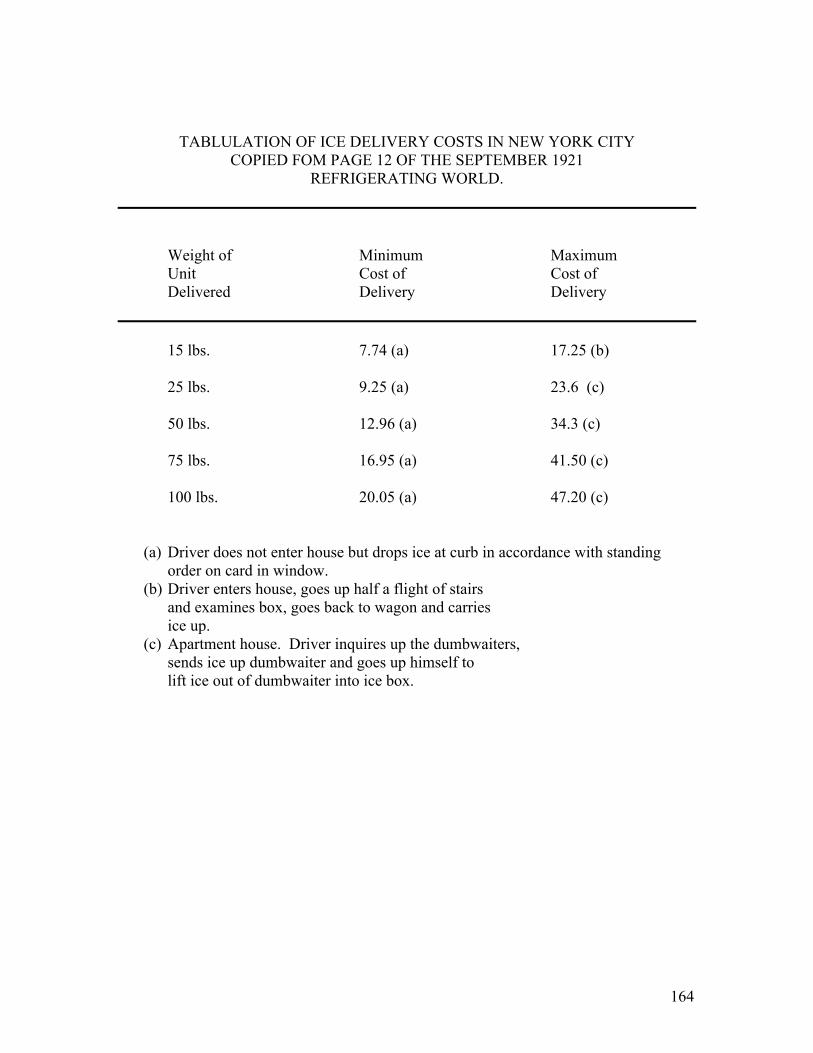
164
TABLULATION OF ICE DELIVERY COSTS IN NEW YORK CITY COPIED FOM PAGE 12 OF THE SEPTEMBER 1921
REFRIGERATING WORLD.
Weight of Minimum Maximum Unit Cost of Cost of Delivered Delivery Delivery 15 lbs. 7.74 (a) 17.25 (b) 25 lbs. 9.25 (a) 23.6 (c) 50 lbs. 12.96 (a) 34.3 (c) 75 lbs. 16.95 (a) 41.50 (c) 100 lbs. 20.05 (a) 47.20 (c)
(a) Driver does not enter house but drops ice at curb in accordance with standing order on card in window.
(b) Driver enters house, goes up half a flight of stairs and examines box, goes back to wagon and carries ice up.
(c) Apartment house. Driver inquires up the dumbwaiters, sends ice up dumbwaiter and goes up himself to lift ice out of dumbwaiter into ice box.

165
APPENDIX #5
Replies From Superintendents of Water Works In Texas, Georgia, and New York State.
Temperature of Water In The Hottest Part of Summer Texas Temperature Price Dallas 90 degrees Fahr. ? Amarillo 87 deg. Fahr. 75 cents per 1000 cu. Ft. Fort Arthur 70 deg. Fahr. 30 cents “ “ gallons Sherman 60 deg. Fahr. ? Texarkana 85 deg. Fahr. 1st 13,500 gals – 50 cents per M Next 48,000 gals – 40 cents per M Next 60,000 gals – 30 cents per M Over 121,000 gals – 20 cents per M Minimum charge per quarter - $3.75 Ranger 70 deg. Fahr. ? Georgia Atlanta Between 75 cents & 90 cents Within city limits – 10 cents per M Out side city limits – 20 cents “ “ Lagrange ? ? Prefer air cooled machines. Augusta ? 1st 1000 gals per day –25 cents M Next 19000 gals per day –20 cents M Next 10000 gals per day –15 cents M Over 30000 gals per day – 12.5 cents M Athens 72 deg. Fahr. 10 cents to 25 cents per M gals. New York Gloversville ? Minimum charge per 6 months $2.00 1st 5000 cu. Ft. – 12 cents per 100 Next 5000 cu. Ft. – 10 cents per 100 Next 5000 cu. Ft. – 8 cents per 100 Next 5000 cu. Ft. – 6 cents per 100 Next 5000 cu. Ft. – 4 cents per 100 Over 25000 cu. Ft. – 3.5 cents per 100
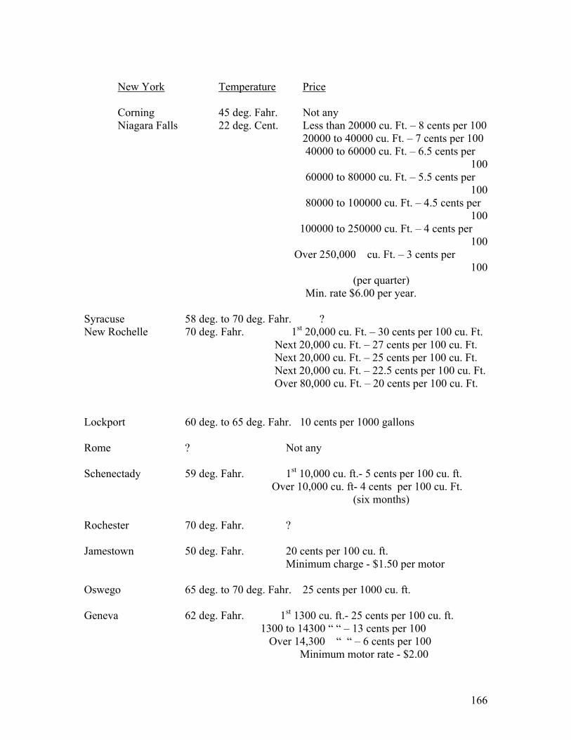
166
New York Temperature Price
Corning 45 deg. Fahr. Not any Niagara Falls 22 deg. Cent. Less than 20000 cu. Ft. – 8 cents per 100 20000 to 40000 cu. Ft. – 7 cents per 100 40000 to 60000 cu. Ft. – 6.5 cents per 100 60000 to 80000 cu. Ft. – 5.5 cents per 100 80000 to 100000 cu. Ft. – 4.5 cents per 100 100000 to 250000 cu. Ft. – 4 cents per 100 Over 250,000 cu. Ft. – 3 cents per 100 (per quarter) Min. rate $6.00 per year. Syracuse 58 deg. to 70 deg. Fahr. ? New Rochelle 70 deg. Fahr. 1st 20,000 cu. Ft. – 30 cents per 100 cu. Ft. Next 20,000 cu. Ft. – 27 cents per 100 cu. Ft. Next 20,000 cu. Ft. – 25 cents per 100 cu. Ft. Next 20,000 cu. Ft. – 22.5 cents per 100 cu. Ft. Over 80,000 cu. Ft. – 20 cents per 100 cu. Ft. Lockport 60 deg. to 65 deg. Fahr. 10 cents per 1000 gallons
Rome ? Not any
Schenectady 59 deg. Fahr. 1st 10,000 cu. ft.- 5 cents per 100 cu. ft. Over 10,000 cu. ft- 4 cents per 100 cu. Ft. (six months) Rochester 70 deg. Fahr. ? Jamestown 50 deg. Fahr. 20 cents per 100 cu. ft. Minimum charge - $1.50 per motor Oswego 65 deg. to 70 deg. Fahr. 25 cents per 1000 cu. ft. Geneva 62 deg. Fahr. 1st 1300 cu. ft.- 25 cents per 100 cu. ft. 1300 to 14300 “ “ – 13 cents per 100 Over 14,300 “ “ – 6 cents per 100 Minimum motor rate - $2.00

167
Elmira 58 deg. in May 1st 1300 cu. ft.– 30 cents per 100 cu. ft. Next 1300 cu. ft.- 26.18 cents per 100 Next 1400 cu. ft.- 22.44 cents per 100 Next 5400 cu. ft.- 15 cents per 100 100000 cu. ft.- 7.5 cents per 100 200000 cu. ft,- 7 cents per 100 Balance - 6 cents
New York Temperature Price Olean From wells 45 deg. to 50 deg. F. ? From creek 75 deg. to 80 deg. F. Ogdensburg 68 deg. Fahr. 10 cents per 1000 gals.
Watertown Same as ground ?
Yonkers 60 deg. Fahr. 16 cents per 100 cu. ft.
Mount Vernon 75 deg. Fahr. 1st 1500 cu. ft.- 32 cents per 100 cu. ft. Next 45000 cu. ft.- 26 cents Next 50000 cu. ft.- 20 cents Over 100000 cu. ft.- 15 cents (within quarter) Kingston ? 1st 1500 cu. ft.- 2.50 Next 3500 cu. ft.- 1.500 per M cu. ft. Next 5000 cu. ft.- 1.00 `` `` `` `` Next 10000 cu. ft.- 70 cents `` `` `` `` Next 20000 cu. ft.- 50 cents `` `` `` `` Minimum motor rater per quarter $3.50 Poughkeepsie 60 deg. Fahr. 1st 10000 cu. ft.- 2.00 per M cu. ft. Next 10000 cu. ft.- 1.75 `` `` `` `` Over 20000 cu. ft.- 1.60 `` `` `` `` Glens Falls ? ? Amsterdam ? 1st 40000 cu. ft.- 8 cents per 100 cu. ft. Next 100000 cu. ft.- 5 cents per 100 Over 140000 cu. ft.- 3 cents per 100 (by quarter)

168
Buffalo 60 deg. to 65 deg. Fahr. Not any Ithaca ? Rates vary from 70 cents per M cu. ft. to $3.50 per M cu. ft. and it will be necessary to refer to Rate Book. Peekskill ? 16 cents per 100 cu. ft. Laskawasso Same as Buffalo Hornell ? ? New York City 73 deg. Fahr. $20 per ton per year for the actual capacity of machine, where rated ton capacity is less than one ton, a charge is made in accordance with the fractional part of a ton, with a minimum charge of $5. per ???.

169
APPENDIX #6
ICE BOXES
*****************
AVERAGE BOX
1. Test Data
Mr. Alder of the Good Housekeeping Institue
made some tests on standard ice boxes to determine the amount
of ice meltage and food compartment temperatures. The boxes tested
were as follows: -
Volume of ice Volume of food Total Rating in compartment compartment Internal Lbs. of ice cu. ft. cu. ft. Volume 125 2.94 5.93 8.87 109 2.2 6.06 8.25 90 2.04 4.97 6.91 ____________________________________________________________ Mr. Alder was not at liberty to tell me
the names of the manufacturers of those boxes, but said
they were of good commercial quality, being sold at from
$70.00 to $100.00. He believed they would have about a ten
year life.
Mr. Alder made several 100 hour tests on
these ice boxes during which the ice was replaced up to
the full capacity of the box every twenty-four hours.
He found that the ice meltage was about .007 lbs. of ice
per hour, per cubic foot of food compartment volume, per
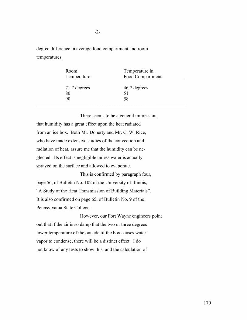
170
-2-
degree difference in average food compartment and room
temperatures.
Room Temperature in Temperature Food Compartment _ 71.7 degrees 46.7 degrees
80 51 90 58
______________________________________________________________ There seems to be a general impression
that humidity has a great effect upon the heat radiated
from an ice box. Both Mr. Doherty and Mr. C. W. Rice,
who have made extensive studies of the convection and
radiation of heat, assure me that the humidity can be ne-
glected. Its effect is negligible unless water is actually
sprayed on the surface and allowed to evaporate.
This is confirmed by paragraph four,
page 56, of Bulletin No. 102 of the University of Illinois,
“A Study of the Heat Transmission of Building Materials”.
It is also confirmed on page 65, of Bulletin No. 9 of the
Pennsylvania State College.
However, our Fort Wayne engineers point
out that if the air is so damp that the two or three degrees
lower temperature of the outside of the box causes water
vapor to condense, there will be a distinct effect. I do
not know of any tests to show this, and the calculation of
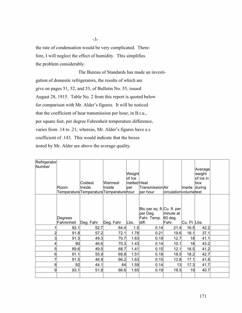
171
-3-
the rate of condensation would be very complicated. There-
fore, I will neglect the effect of humidity. This simplifies
the problem considerably.
The Bureau of Standards has made an investi-
gation of domestic refrigerators, the results of which are
give on pages 51, 52, and 53, of Bulletin No. 55, issued
August 28, 1915. Table No. 2 from this report is quoted below
for comparison with Mr. Alder’s figures. It will be noticed
that the coefficient of heat transmission per hour, in B.t.u.,
per square feet, per degree Fahrenheit temperature difference,
varies from .14 to .21; whereas, Mr. Alder’s figures have a c
coefficient of .143. This would indicate that the boxes
tested by Mr. Alder are above the average quality.
Refrigerator Number
Room Temperature
Coldest Inside Temperature
Warmest Inside Temperature
Weight of Ice melted per hour
Heat Transmission per hour
Air circulation
Inside volume
Average weight of ice in box during test
Degrees Fahrenheit Deg. Fahr Deg. Fahr Lbs.
Btu per sq. ft. per Deg. Fahr. Temp. diff.
Cu. ft. per minute at 60 deg. Fahr. Cu. Ft. Lbs.
1 92.1 52.7 64.4 1.5 0.14 21.4 16.5 42.2 2 91.8 57.2 72.1 1.78 0.21 19.6 18.1 37.1 3 91.3 49.3 70.7 1.63 0.19 12.7 18 41.1 4 90 46.6 70.3 1.43 0.14 10.1 18 43.2 5 89.6 49.5 68.7 1.41 0.15 12.1 16.5 41.2 6 91.1 55.9 69.8 1.51 0.18 18.5 18.2 42.7 7 91.5 46.9 66.2 1.63 0.15 13.8 17.1 41.8 8 92 44.1 64 1.59 0.14 13 17.3 41.7 9 93.1 51.8 66.6 1.65 0.19 18.5 19 40.7

172
-4- I wrote to eighty-one manufactures of ice
boxes asking for scientific data and only eight were able
to give intelligent replies.
There is a special appendix on the ice box
manufactured by the American Balsa Company, which I believe
to be the best box on the market from both the standpoint of
efficiency and cost.
2. Analysis of Operation with Ice
a. The first three lines of the following
table are obtained directly from Mr. Alder’s figures for the
on hundred pound box.

173
-5-
TABLE #
Ice Metage Lbs. Per
Hour
Temp of Ice
Diff. In Temp
Temp. of Food
Diff in Temp
Room Temp
Type of Insulations
Insulated Area in Sq. Ft.
B.t.u. per sq. ft., per hour, per degree
1 1.06 # 32 deg. 14.7 deg. 46.7 deg. 25 deg. 71.7 deg. Standard 42.5 0.143 2 1.23 32 19 51 29 80 Standard 42.5 0.143 3 1.36 32 26 58 32 90 Standard 42.5 0.143 4 1.28 20 20 40 30 70 Standard 42.5 0.143 5 2.12 -9 49 40 50 90 Standard 42.5 0.143
6 0.8 32 8 40 30 70
1 inch additional
cork 42.5 0.0905
7 1.12 32 16 48 42 90
1 inch additional
cork 42.5 0.0905
8 0.8 32 8 40 50 90
3 inch additional
cork 42.5 0.054
9 0.55 32 2.5 34.5 35.5 70
3 inch additional
cork 42.5 0.054
Foot-note (/-): The outside dimensions of the box are assumed 46`` high,
32.5`` wide, 19.5`` deep.
Foot-note (#): These temperatures are assumed to be obtained by the
use of ordinary salt or calcium chloride crystals.
b. It will be noted that Mr. Alder’s
figures assume that the heat transmission through the
box insulation is a linear function of the temperature
drop between the outside air and the food compartment.
This is theoretically correct if the contact resistance
Between the air and the box can be neglected.

174
-6-
c. Mr. C. W. Rice has given me a formula
for the contact resistance to the flow of heat from a
cylinder. This formula is for convection only. Mr. Rice’s
formula shows that although the contact resistance cannot
be neglected, it can be considered as practically a linear
function within the range of temperatures under discussion.
Foot-note (#): Mr. Rice will read a paper, “Free and Forced
Convection of Heat in Gases and Liquids”, at
the June, 1923, A.I.E.E Convention.
Other papers on the laws of Heat and Trans-
mission are:
1. Laws of Heat Transmission in
Electrical Machinery
I. Langmuir
A.I.E.E. Feb., 1913.
2. Convection and Radiation of Heat
I. Langmuir
American Electrochem Society
Vol. XXIII, Pge. 299-332
April, 1913.

175
-7-
3. Convection and Conduction of Heat in Gases
Physical Review – 1912.
4. Thermal Condensation and Convection in
Gases at High Temperatures.
Transaction from American Electrochem
Society – 1911.

176
-8-
On page 40 of the University of Illinois Bulletin NO. 102, a formula is given for the
contact resistance, from which a temperature difference of 2.6 F could be calculated.
This is 23.3 percent less than Mr. Rice’s formula. I should not expect a much closer
check than this.
About the same drop could be calculated
from the inside of the box to the air in the food compart-
ment. This makes a total contact drop of 6.4 degrees F. The
total drop was 25 degrees: therefore, the drop through the
insulation must have been about 18.6 degrees. The insulation was
apparently equivalent to 1 1/3 inches of cork.
In general, it will be noted that in the
range of temperatures under consideration the contact re-
sistance can be considered linear, and, therefore, lumped
with the insulation resistance.
d. An analysis shows that at least within
the range of Mr. Alder’s tests, the rise in temperature
between the ice and the center of the food compartment has
a variation which is proportional to the convection be-
tween two chambers at these temperatures.

177
-9-
e. The attached maps of the climate show
(Editors note: faded beyond recongnition )
the temperatures which will be encountered all over the
United States.
I have decided it would be unreasonable
to design the boxes for the extreme temperature of 110 degrees,
but believe that the box should be suitable for use in
room temperatures up to 90 degrees F.
Dr. John R. Williams, Secretary of the
Milk Commission, Rochester, New York, in a paper before the
Third International Congress of Refrigeration, in 1913,
states:
(EDITORS NOTE: remaining pages are missing)

178
January 17, 1924
APPENDIX # 6-A
REFRIGERATOR SUGGESTED BY Mr. A. L. GIVENS
***************
Mr. Givens has suggested a new principle of
refrigerator, which system might be termed a “prevention”
rather that a “cure”. In previous practice, the heat has been
allowed to leak into the refrigerator through insulation, and
has then been removed from the refrigerator by air convection
to a brine tank. Mr. Givens suggests that the cooling unit,
either brine tank or trays containing melting ice, be connec-
ted directly to the sheet metal, enameled lining of the re-
frigerator. Any heat leaking through the cork insulation
would be caught on the sheet metal lining and conducted di-
rectly to the cooling unit. Mr. Givens has suggested that the
cooling unit might be mounted in the center of the box.
The enameled sheet steel linings of refri-
gerators, I understand, are usually 1/16” thick. It would
probably be advisable in making a refrigerator along the lines
of Mr. Givens’ suggestion to use at least 1/8” steel, in which
case the lining should not rise higher than 49.4°F., at the
point farthest from the refrigerating unit. In these calcula-
tions, it has been assumed that any heat which leaks in through
the door of the refrigerator will be convected through the in-
terior air to the wall of the food compartment which is next the
cooling unit.
This construction has the great advantage that
each food compartment will be complete will be complete in itself, the porcelain

179
lining having rounded corners which can easily by cleaned. None
of the oil vapors from the food will be carried over the ice
trays, as in the Savage Arms design. It will, therefore, be
unnecessary to clean the ice trays or the brine tank, if a
brine tank should be used.

180
APPENDIX #7
DISCUSSION OF THE FACTORS WHICH INFLUENCE THE RATING OF A
DOMESTIC REFRIGERATING MACHINE.
********************************
1. The table on page 5 of appendix #6 shows that to
maintain a temperature of 40° in a standard hundred
pound ice box with a room temperature of 90°, would require
a brine tank temperature of –9°F. and a rate of ice meltage
of about 2.12 lbs. of ice per hour.
On account of the danger of freezing up the oil,
it would probably be inadvisable with most types of
refrigerating machines to attempt to carry the brine at
a temperature lower than plus 20°F.
With the brine tank at 20°F. on a 90°
day, the food compartment would be about 52 ½° and
the rate of ice meltage would be 1.6 lbs. per hour.
Therefore, unless the refrigerating machine is
of a type which can be operated with a brine tank tempera-
ture of less than 20°, it would be impossible to
produce good refrigeration (food compartment temperatures
less than 45°) in a standard 100 lb. box on a 90° day,
unless the air circulation is improved.
But, for the sake of argument, assume that the
refrigerating machine can be operated with a brine
temperature of –9°. In order to refrigerate the box on a
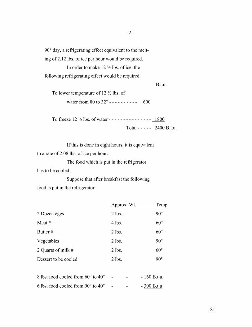
181
-2-
90° day, a refrigerating effect equivalent to the melt-
ing of 2.12 lbs. of ice per hour would be required.
In order to make 12 ½ lbs. of ice, the
following refrigerating effect would be required.
B.t.u.
To lower temperature of 12 ½ lbs. of
water from 80 to 32° - - - - - - - - - - 600
To freeze 12 ½ lbs. of water - - - - - - - - - - - - - - - 1800
Total - - - - - 2400 B.t.u.
If this is done in eight hours, it is equivalent
to a rate of 2.08 lbs. of ice per hour.
The food which is put in the refrigerator
has to be cooled.
Suppose that after breakfast the following
food is put in the refrigerator.
Approx. Wt. Temp.
2 Dozen eggs 2 lbs. 90°
Meat # 4 lbs. 60°
Butter # 2 lbs. 60°
Vegetables 2 lbs. 90°
2 Quarts of milk # 2 lbs. 60°
Dessert to be cooled 2 lbs. 90°
8 lbs. food cooled from 60° to 40° - - - 160 B.t.u.
6 lbs. food cooled from 90° to 40° - - - 300 B.t.u

182
Total - - - 460 B.t.u.
Foot-note (#): It is assumed that these articles are delivered
promptly from the store and have not warmed up to room tem-
perature. Assume the specific heat of all of these to be unity.

183
-3-
If this is done in three hours, it is equi-
valent to a rate of 1.06 lbs. of ice per hour.
What is the effect of opening the door of
the refrigerator? Suppose that each time the refrigerator
is opened the whole food compartment fills with 90° air at
100 percent humidity. The food compartment has a capacity of
6.05 cu. Ft. This would represent .414 lbs. of air. In
cooling this 90° air to 40°, about .011 lbs. of water will be
condensed. The refrigerating effect required to cool the air
and condense the water will be 16.8 B.t.u., which is equivalent
to .1165 lbs. of ice. If the box is opened twelve times an
hour, it is likely that 1.42 additional pounds of ice would be
melted. The engineer of the Arlington Refrigerator Company,
who was formerly with the Toledo Coldmaker Company, made some
tests to determine the effect of opening the door of the re-
refrigerator. He found that frequent opening and closing of the
door increased the amount of ice meltage 27 percent. I have
assumed that the refrigerator will be opened twelve times an
hour in order to make an increase of 27 percent.
Adding all these together, the peak lead on
the refrigerating machine would be,
Rate in lbs. of
Ice per hour
To hold box at 40° with room at 90° - - - - 2.12
To freeze 12 ½ lbs. of ice in eight hours - - - 2.08
To cool food in three hours - - - - - 1.06
Opening the box twelve times - - - - - 1.42
Total - - - - - 6.68

184
-4-
This is equivalent to a maximum rating of
160 lbs. of ice per twenty-four hours.
However, the average load would be much
less than this.
Lbs. of ice per
24 Hours
To hold box at 40° with room at 70° - - 30.8
To freeze 12 ½ lbs. ice once in 24 hours - 15.7
To cool food once in twenty-four hours - 2.35
Opening the box twenty-five times, each
time filling with 70° air at 66%
humidity - - - - .82
Average daily consumption - - - 49.67
The new Fort Wayne type OC-2, form G machine
would not be capable of holding the food compartment of this
box at 40° on a 90 degree day, because the oil would freeze
up if it was run with a brine temperature of -9°. Further,
even if the oil did not freeze up, the capacity of the
machine would only be about 80 lbs. of ice per twenty-four
hours at this brine temperature, whereas, 160 lbs. of ice
would be required.
On the other hand, a brine temperature of
20° would be correct for this box on an average 70 degree
day. The Fort Wayne type OC-2, form G machine is capable of
operation under this condition with approximately 45.5 watt-
hours per pound of ice. It would, therefore, require 2.26 KW-
hours per day.

185
-5-
Let us see what rating of machine would be
required for use with a special 100 lb. box having an addi-
tional inch of cork insulation. (This would make a total
insulation equivalent to 2 1/3 inches of Non-Pareil corkboard.)
In this case, on an average 70 degree day,
the brine tank could be run at 32°, thereby obtaining a food
compartment temperature of 40°, and the rate of ice meltage
would only be .8 lbs. of ice per hour.
In order to maintain a 40° food compartment
on a 90° day, it would be necessary to hold the brine
tank at 18° and the rate of ice meltage would be 1.3 lbs.
per hour.
Rate in lbs. of Ice per hour To hold the box at 40° with room at 90° - - - - 1.33
To freeze 12 ½ lbs. ice in eight hours - - - - - - 2.08
To cool food in three hours - - - - - - - - - - - - - 1.06
Total - - - - - - - - - - - - - 4.47
This is equivalent to a maximum rating of
about 108 lbs. of ice per twenty-four hours.
On the average 70 degree day, however,
Lbs. of ice per 24 hours To hold box at 40° with room at 70° - - - - - - 19.2
To freeze 12 ½ lbs. ice once a day - - - - - - - 15.7
To cool food once a day - - - - - - - - - - - - - - 2.35
Opening box twenty-five times - - - - - - - - - .82
Total - - - - - - 38.07
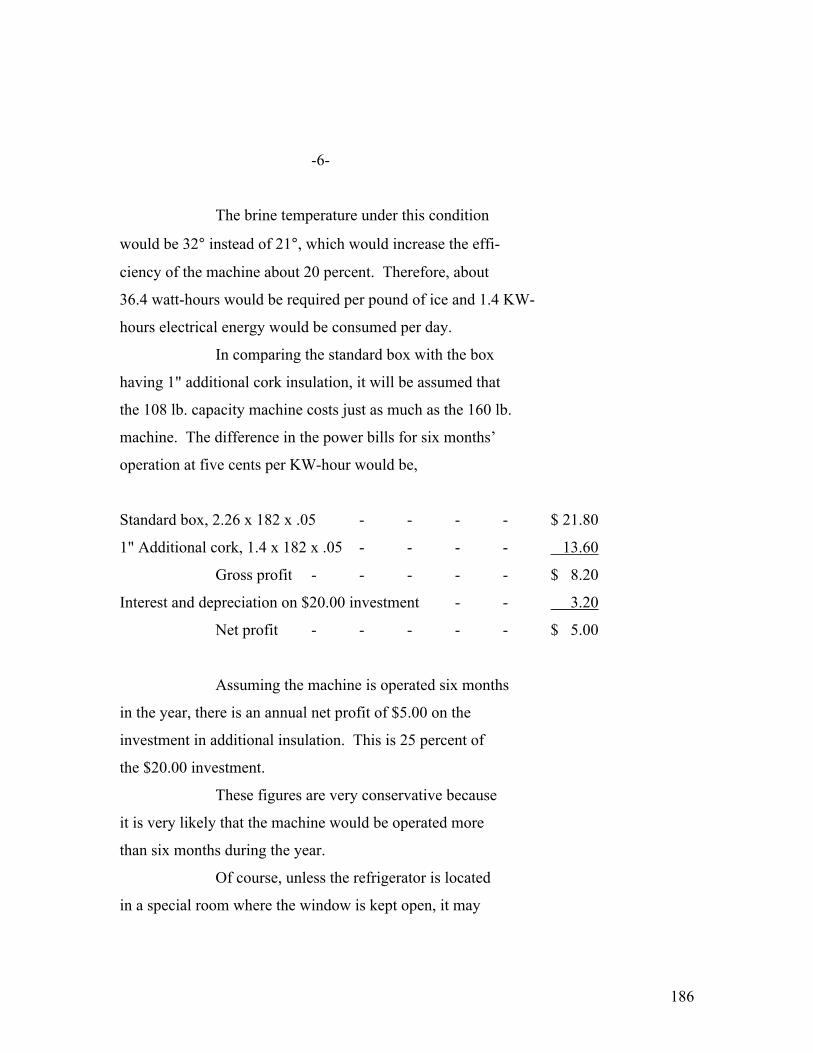
186
-6-
The brine temperature under this condition
would be 32° instead of 21°, which would increase the effi-
ciency of the machine about 20 percent. Therefore, about
36.4 watt-hours would be required per pound of ice and 1.4 KW-
hours electrical energy would be consumed per day.
In comparing the standard box with the box
having 1" additional cork insulation, it will be assumed that
the 108 lb. capacity machine costs just as much as the 160 lb.
machine. The difference in the power bills for six months’
operation at five cents per KW-hour would be,
Standard box, 2.26 x 182 x .05 - - - - $ 21.80
1" Additional cork, 1.4 x 182 x .05 - - - - 13.60
Gross profit - - - - - $ 8.20
Interest and depreciation on $20.00 investment - - 3.20
Net profit - - - - - $ 5.00
Assuming the machine is operated six months
in the year, there is an annual net profit of $5.00 on the
investment in additional insulation. This is 25 percent of
the $20.00 investment.
These figures are very conservative because
it is very likely that the machine would be operated more
than six months during the year.
Of course, unless the refrigerator is located
in a special room where the window is kept open, it may

187
-7-
possibly have to run with a 70° room temperature all
the year. Mr. C. K. Nichols, sales manager of the New York
Edison Company, is preparing figures for a report which will
be read at the October meeting of the National Association of
Edison Illuminating Companies. These figures have not been
tabulated in scientific form as yet, but I had a chance to
glance over them in Mr. Nichols’ office, and my impression is
that most of the machines carried about an average load all
winter. For instance, one machine averaged 2 KW-hours per
day for the year, but during the month of July the average was
2.3 KW-hours per day. Other machines averaged for the year
2.8 KW-hours, 2.7 KW-hours, 1.8 KW-hours, and 1.73 KW-hours.
If three extra inches of cork are added
(making a total insulation equivalent to 4 1/3 inches of
cork), the peak load of the machine would be reduced to a
rating of 95 lbs. of ice per twenty-four hours. The average
load would be 30.07 lbs. of ice per day, and the brine tank
could be run at 37 ½ degrees. The watt-hours per pound
of ice would be 32.5.
The power bill for six months would compare
as follows:
Standard box - - - - - $ 21.80 Three extra inches of cork - - - 9.00
Gross profit - - - $ 12.80
Interest and depreciation on $60.00 investment 9.60
Net profit - - - $ 3.20

188
-8-
It will be noticed that the net profit is
5 1/3 percent of the $60.00 investment.
THE FRIGIDAIRE HAS A 9 cu. ft. BOX WITH TWO
INCHES OF CORK INSULLATION, AND MAKES 9 lbs. OF ICE PER DAY.
The insulation consists of 2 inches of cork
board, five ply laminated wood, and porcelain lining.
The outside area is 73 sq. ft
If the insulation is the equivalent of
2 1/3 inches of cork, the heat transfer on a 70 degree day
through 73 sq. ft. to a 40 degree internal temperature would
be about 1.37 lbs. of ice per hour.
Therefore, the average load would be,
Lbs. ice per
24 hours
To hold a temperature of 40° - - - - - - 33 lbs.
To freeze 9 lbs. of ice - - - - - - - - - - - 11.3 lbs.
To cool food - - - - - - - - - - - - - - - - - 2.35 lbs.
Total - - - - - - - - - - - - 46.65 lbs.
If the machine has the same efficiency as
the Fort Wayne type OC-2 machine, this corresponds to about
2.14 KW-hours per day.
This checks very well with the actual per-
formances. Mr. T. I. Jones’ paper gave a figure of 1.8 KW-
hours per day this machine. Mr. Grant told me the
latest figure was 1 ½ KW-hours, average for the year. Of
course, during the winter months the temperature might be

189
-9-
less than 70 degrees, which would bring down the average.
It is interesting to calculate that the
12 ½ lbs. of ice for table use is made with an expenditure
of only .71 KW-hours, or about 3 ½ cents, if the power
costs five cents per KW-hour. This corresponds to 28 ½ cents
per hundred-weight, whereas the purchase price of ice is about
60 cents to 80 cents per hundred-weight.
THE FORT WAYNE TYPE OC-2 MACHINE IS INSTALLED
IN A JEWETT REFRIGERATOR WHICH HAS,
1 – Interior space – 25.7 cu. ft. 2 – Food compartment – 19.5 cu. ft. 3 – Insulated area – 45" x 19" x 52" – 58 sq. ft. 4 – Insulation – 7/8" ash case, 2 courses waterproof paper, 2 courses 1 ½" corkboard,
½ " granulated – cork with binder. White vitreous porcelain on 18 gauge steel.
I assume that this total insulation is equi- valent to 3 ¾" of cork. 5 – The machine is arranged so that the temperature in the food compartment varies from 42° to 48°. The average is actually 46° 6 – The brine tank temperatures vary from 18° to 26° F. 7 – The area of the brine tank is 9.3 sq. ft. 8 – Mr. Crane estimates that the inside of the expansion coils will be 2° lower than the brine temperature. 9 – The area of the expansion coils is 7.7 sq. ft.
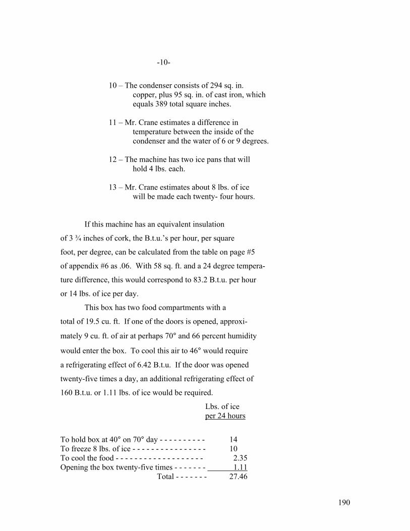
190
-10-
10 – The condenser consists of 294 sq. in. copper, plus 95 sq. in. of cast iron, which equals 389 total square inches. 11 – Mr. Crane estimates a difference in temperature between the inside of the condenser and the water of 6 or 9 degrees. 12 – The machine has two ice pans that will hold 4 lbs. each. 13 – Mr. Crane estimates about 8 lbs. of ice will be made each twenty- four hours. If this machine has an equivalent insulation
of 3 ¾ inches of cork, the B.t.u.’s per hour, per square
foot, per degree, can be calculated from the table on page #5
of appendix #6 as .06. With 58 sq. ft. and a 24 degree tempera-
ture difference, this would correspond to 83.2 B.t.u. per hour
or 14 lbs. of ice per day.
This box has two food compartments with a
total of 19.5 cu. ft. If one of the doors is opened, approxi-
mately 9 cu. ft. of air at perhaps 70° and 66 percent humidity
would enter the box. To cool this air to 46° would require
a refrigerating effect of 6.42 B.t.u. If the door was opened
twenty-five times a day, an additional refrigerating effect of
160 B.t.u. or 1.11 lbs. of ice would be required.
Lbs. of ice per 24 hours
To hold box at 40° on 70° day - - - - - - - - - - 14 To freeze 8 lbs. of ice - - - - - - - - - - - - - - - - 10 To cool the food - - - - - - - - - - - - - - - - - - - 2.35 Opening the box twenty-five times - - - - - - - 1.11 Total - - - - - - - 27.46

191
-11-
The old type OC-2, form E machine required
40.5 watt-hours per pound of ice. Therefore, the theoretical
KW-hour consumption on an average 70 degree day would be 1.11.
The figures which Mr. Riffel took on Mr.
Waters’ machine show that the average of July, August, Sep-
tember, October and November, was 1.45 KW-hours per day. The
variation was from 2.28 KW-hours in July down to .85 KW-hours
in October.
It is also interesting to note that the
water consumed by this machine during the same period averaged
4.72cu. ft. per day. # This varied from 7.85 cu. ft. in July
down to 2.5 cu. ft. in November. At an average rate of 4.72
cu. ft. per day, in six months only 860 cu. ft. would be used.
At $1.00 per thousand cubic feet, this would correspond to a
water bill of 86 cents. The amount of water taken by this
machine is apparently very much less than that required by
- - - - - - - - - - - - - - - -
Foot- note (#): There is some question as to the accuracy of the water meter at Mr. Waters’ machine, but these readings check very well with the data obtained from tests at Fort Wayne. The machine running with an input of 340 watts, took eight gallons of water a day. If the power for the
day is only 1.45 KW-hours, the machine only ran 18% of the time. It would therefore take 34 ½ gallons of 4.6 cu. ft. of water per day.

192
-12-
the Frigidaire. The Frigidaire, Model B-15, in advertised as
taking from 20 to 30 cu. ft. per day average, which is from
four to six times as much as this type OC-2 machine. This
particular size of Frigidaire machine refrigerates 15.5 cu. ft.,
whereas the type OC-2 machine refrigerates 19.5 cu. ft.

193
APPENDIX 8
ANALYSIS OF TEST ON
TYPE OC-2 FORM “F” MACHINE
********************
Mr. Hunting’s report of January 31, 1922,
page 29, together with information contained in Mr. Crane’s
letter of July 5, gives the following test figures:
Capacity - - - - - 1210 B.t.u. per hour
Condensing water enters at - - - 58 degrees
Condensing water leaves condenser at - 77 degrees
Condensing water leaves water jacket at - 88 degrees
Condensing water - - - - 8 gallons per hour
raised 30° F.
Condenser pressure - - - - 48 lbs.
Brine temperature - - - - 23° Fahrenheit
Power input - - - - - .28 watt-hours per
B.t.u.
In appendix #11, “Comparison of Various
Refrigerants”, it was shown that the theoretical coefficient
of performance for sulphur dioxide between these temperatures
is 7.11 for wet compression and 6.96 for dry compression.
If we assume wet compression, then
1210/7.11 = 170 B.t.u. work will be required per hour to
produce a refrigerating effect of 1210 B.t.u. If this work
is done in one hours, the theoretical horsepower required
will be .0666. Assume two degrees difference in temperature

194
-2-
between the brine and the inside of the expansion coils.
This makes an expansion coil temperature of 21°. Neglecting
efficiency, this corresponds to 49 ½ watts.
But, the electrical input was 340 watts.
Therefore, the losses in the motor and compressor must have
been 290.5 watts which, expressed in heat units, is equiva-
lent to 995 B.t.u. per hour. On the temperature-entropy
diagram H-99384, which shows the wet compression of one pound
of sulphur dioxide, it will be noted that the condenser must
absorb 162.5 B.t.u. for every pound of sulphur dioxide cir-
culated. It will be necessary to circulate 8 ½ lbs. of
sulphur dioxide per hour to obtain a rating of 1210 B.t.u.
per hour. Therefore, the condenser must absorb 1380 B.t.u.
Heat given off in the condenser by the cooling
and liquefaction of the sulphur dioxide - - - - - 1380 B.t.u.
Heat equivalent of the losses - - - - - - - - - - - - - - - - - 995 ``
Total - - - - - - - - - - - - - - - - - - 2375 B.t.u.
Heat taken up by eight gallons of cooling
water raised 30 degrees - - - - - - - - - - - - - - - - 2010 ``
Difference - - - - - - - - - - - - - - 365 B.t.u
Therefore, 365 B.t.u. per hour must have
been radiated and convected from the case of the OC-2 machine.
The volume of 8 ½ lbs. of sulphur dioxide
vapor at 21° F. is 38 cu. ft. Therefore, 38 cu. ft. of gas

195
-3-
must have been pumped per hour. The compressor of this
form F machine had a displacement of 70 cu. ft. per hour.
Therefore, the volumetric efficiency is about 54 percent.
If this low volumetric efficiency were due to a large clearance
in the end of the cylinder, it would not necessarily represent
a power loss, but the clearance in these machines is very small,
being a fraction of a percent. Therefore, most of this loss
must be slippage past the piston. This seems like a very
excessive slippage loss, but it might possibly be due to the
fact that there are no piston rings in this type of compressor.
If this 46 percent loss in volume is due to
slippage, it means that the indicated horsepower of the com-
pressor is approximately 46 percent larger than would other0
wise be the case. The indicated horsepower is, therefore,
.0666 = .1225. 54
The motor efficiency is assumed to be 60 per-
cent so that with an input of 340 watts the output would be
.274 horsepower.
Therefore, the mechanical efficiency of the
pump must be .1225/274 = 45 percent.
The overall efficiency of the machine from
the electrical input to the motor to the theoretical horse-
power required to compress the gas would be .0666.456 =
14.6 percent.

196
-4-
This is assumed to be distributed as
follows:
Motor efficiency - - - - - - - - 60%
Mechanical efficiency - - - - 45%
Volumetric efficiency
due to slippage - - - - 54%
The heat given to the cooling water can be
determined as follows:
Water enters - - - - - - - - - - - - - - - - - - - - - - 58°
1380 B.t.u. given to the condenser by
8 gallons of water causes a rise of - - 20 ½ °
Water must leave the condenser at - - - - - - - 78 ½ °
Since the water leaves the water jacket
at 88 degrees, it could only have risen 9 ½ °, which
would correspond to 630 B.t.u.
Temperature of the sulphur dioxide at 48 lbs. - - - - 82 ½ °
The average condenser temperature - - - - - - - - - - - 68 ¼ °
Difference in temperature between the water
and the sulphur dioxide - - - - - - - - - - - - - - 14 ¼ °
These tests are on the old Fort Wayne
type OC-2, form F machine, which had a slow compressor con-
sisting of two double acting cylinders with cranks at right
angles geared to the motor. Within the last six months, the
type OC-2 machine has been redesigned, the newer model

197
-5-
being called form G. This new machine has two single acting
cylinders, direct connected to the motor. Tests on this new
machine show a power consumption of .315 watt-hours per B.t.u.
which is 12 percent more than with the old form F machine.
The Fort Wayne engineers suggest that this additional loss is
due to the more rapid stirring of the oil. I think it is
probably due to the lower volumetric efficiency of the high
speed compressor for the following reasons:
The capacity of the machine with 21° brine
is only 1025 B.t.u. Therefore, only 32 cu. ft. of vapor
must be pumped.
The displacement of the machine is 71 cu. ft.
This makes a volumetric efficiency of 45 percent as compared
with the 54 percent volumetric efficiency of the old form F
machine.
I believe this would easily account for the.
additional 12 percent power required.
Condenser
In the above calculations, it was assumed
that the average drop between the gas in the condenser and
the cooling water was 15 degrees. The area of the condenser
is 389 sq. in. 294 sq. in. of this consists of the 9/16 inch
inside diameter pipe carrying water at the rate of eight
gallons per hour. This corresponds to 0.173 feet per second.

198
-6-
On page 187 of “Elements of Refrigeration”, by A. M. Green, Jr.,
there is a formula credited to R. L. Shipman,
K = 130 √W
Where, K = B.t.u. per square foot, per hour,
per degree.
W = Velocity of water in feet per second.
Substituting a velocity of water of .173 ft.
per second, the value of “K” becomes 54.
Therefore, the B.t.u. transfer through the
294 square inches of pipe, with an average difference in
temperature of 15 degrees, would be,
B.t.u. = 54 × 294/144 × 15 = 1650
The actual heat transfer was 1380 B.t.u.
I have not calculated the heat transfer in
the cast iron portions because the velocity of flow would be
very small, making a very small value of “K”.
Expansion Coils The assumption of 2 degrees drop between
the brine and the expansion coils was apparently not so con-
servative because the value of “K” for brine coolers given
on page 189 of Professor Greene’s book is 50. The expansion
coils have 7.7 square feet. The heat transfer was 1210.
This requires a 3.16 degree difference.
199
APPENDIX # 8-A.
**********
ANALYSIS OF TESTS ON TYPE OC-2 FORM G MACHINE NO. 100 37-G. ********* EDITOR’s note: diagrams or pictures referenced are too faded to be included
SUMMARY The Carnot cycle coefficient of performance is,
___T² _
T¹ - T²
Although the absolute values of the coefficient of performance
of a sulphur dioxide cycle and a Carnot cycle are not the same,
for different conditions, their variation is proportional within
an error of about 2 ½ %.
The overall efficiency of the motor and compressor
= thermodynamic work divided by electrical input expressed in
B.t.u. = a constant = 15.4%.
Since the overall efficiency is a constant, the
actual electrical power per B.t.u. refrigerating effect will
vary as the coefficient of performance. Therefore, if you have
a test in which the electrical input per B.t.u. is E when the
absolute temperature of the expansion coils is T² and the abso-
lute temperature of the condenser T¹, then the electrical in-
put per B.t.u., E`, for the same machine operating between an
expansion coil temperature T²` and a condenser temperature T¹`
will be,
E` = E × ( T¹` - T² ) × ( T² ) T²` T¹ - T²

200
-2-
It will be quite interesting to see whether this
formula will check tests which are made over a wider range
of temperatures.
The volumetric efficiency corresponding to the
tests varies from 56% down to 46.7%. This could be accounted
for by a 38.9% leakage and the re-expansion of a 12 ½ %
clearance volume. I am wondering whether there is a suffi-
ciently large bubble of gas still under the snifter discharge
valve at the end of the compression stroke which might be
sucked back into the cylinder, re-expanding and thus giving
the effect of 12 ½ % clearance.
I - INTRODUCTION When I was in Fort Wayne a short time ago, Mr.
Clark Orr called my attention to the following tests on ma-
chine #10037-G.
TABLE I
Brine :Condenser Gauge :Refrigerating :Electrical Input Temperature : Pressure :Effect : : :BTU per hour : Watts ____________:_________________ :___________ :________________
20° : 48 lbs. : 980 : 265 20° : 58 lbs. : 850 : 266 20° : 69 lbs. : 785 : 275
__________________________________________________________
These figures are plotted on H-108944. Mr. Orr
felt that it was very peculiar that this curve was concave up-
ward. The fact that the curve is concave upward looks very
promising for an air cooled machine because it shows that as
(Editors note: 2 pages of diagrams faded beyond recognition)

201
-3-
the condenser pressure rises and the temperature rises, the
capacity of the machine falls off less rapidly than might
otherwise be expected.
II- TEMPERATURE ENTROPY DIAGRAM – H-108945 The calculations for this diagram are given in
Section VI at the end of this appendix. The diagram is based
on the circulation of one pound of sulpur dioxide. The hori-
zontal distance across the bottom represents the refrigeration
which can be obtained by circulating one pound of sulpur
dioxide. It will be noticed that due to the evaporation going
through the expansion valve and due to the required moisture
in order to maintain wet compression in the compressor, the
possible refrigeration is considerably less than the latest
heat of evaporation of one pound.
The following calculations are for three different
conditions, all with a brine temperature of 20° Fahrenheit. I
have chosen even temperatures of 80°, 90°, and 100°, because
it avoids interpolations in the tables.
(Editors note: 2 pages of diagrams faded beyond recognition)
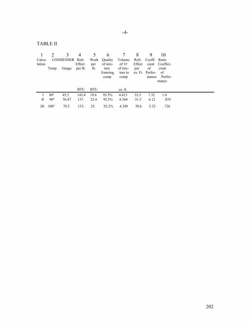
202
-4- TABLE II 1 2 3 4 5 6 7 8 9 10 Calcu- CONDENSER Refr. Work Quality Volume Refr. Coeffi Ratio lation Effect per of mix- of 1# Effect cient Coeffici- Temp. Guage per lb. lb. ture of mix- per of cient Entering ture to cu. Ft. Perfor- of comp comp mance Perfor- mance BTU BTU cu. ft. I 80° 45.2 143.4 19.6 93.5% 4.413 32.5 7.32 1.0 II 90° 56.87 137. 22.4 92.5% 4.364 31.5 6.12 .835
III 100° 70.2 133. 25. 92.2% 4.349 30.6 5.32 .726

203
-5- Column 4 is the refrigerating effect per pound, taken from the temperature-entropy diagram. Column 5 is the thermodynamic work theoretically required to compress a pound of sulphur dioxide from the ex- pansion coil pressure to the condenser pressure. Column 8 is the refrigerating effect per cubic feet actually pumped. It is the quotient of Column 4 divided by the thermodynamic work in Column 5. Column 10 is the ratio of the coefficient of per- formance in calculation II and III to the coefficient of per- formance in calculation I. In order to show that the variation in the coeffi-
cient of performance is dependent on the expansion and con-
denser temperatures, Table III has been prepared.
TABLE III
Calcu-: Tempe-: T¹ : T² : T¹ - T² : Carnot cycle : Ratio : lation : rature : : : : Coefficient : Coefficients of : : : : : : of Perfor- : Performance : : : : : : mance : : I : 80 : 540: 480 : 60 : 8.0 : 1.0 II : 90 : 550: 480 : 70 : 6.85 : .86 III : 100 : 560: 480 : 80 : 6.0 : .75 _____________________________________________________
Column 3 is the absolute condenser temperatures. It
is the temperature in Column 2 plus 460.
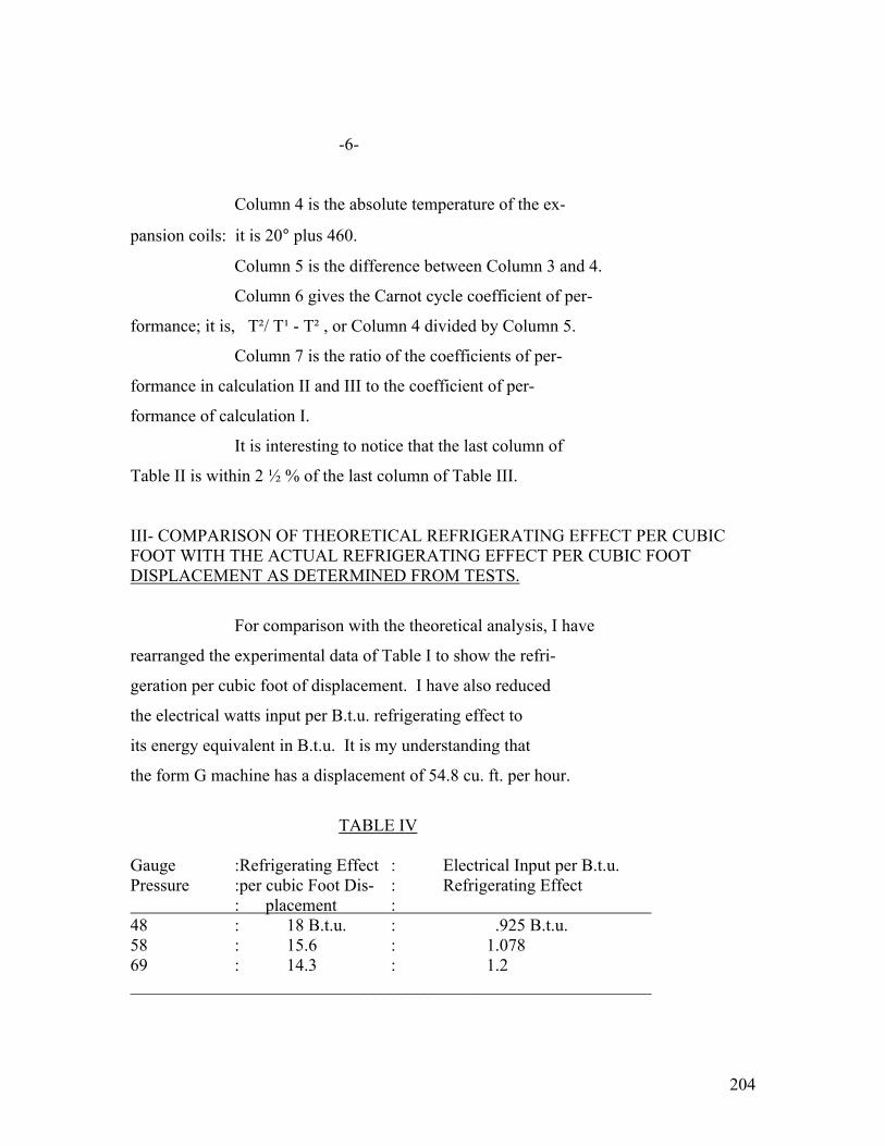
204
-6-
Column 4 is the absolute temperature of the ex-
pansion coils: it is 20° plus 460.
Column 5 is the difference between Column 3 and 4.
Column 6 gives the Carnot cycle coefficient of per-
formance; it is, T²/ T¹ - T² , or Column 4 divided by Column 5.
Column 7 is the ratio of the coefficients of per-
formance in calculation II and III to the coefficient of per-
formance of calculation I.
It is interesting to notice that the last column of
Table II is within 2 ½ % of the last column of Table III.
III- COMPARISON OF THEORETICAL REFRIGERATING EFFECT PER CUBIC FOOT WITH THE ACTUAL REFRIGERATING EFFECT PER CUBIC FOOT DISPLACEMENT AS DETERMINED FROM TESTS.
For comparison with the theoretical analysis, I have
rearranged the experimental data of Table I to show the refri-
geration per cubic foot of displacement. I have also reduced
the electrical watts input per B.t.u. refrigerating effect to
its energy equivalent in B.t.u. It is my understanding that
the form G machine has a displacement of 54.8 cu. ft. per hour.
TABLE IV Gauge :Refrigerating Effect : Electrical Input per B.t.u. Pressure :per cubic Foot Dis- : Refrigerating Effect : placement : 48 : 18 B.t.u. : .925 B.t.u. 58 : 15.6 : 1.078 69 : 14.3 : 1.2 ____________________________________________________________

205
-7-
Curve I on H-105447 is the refrigerating effect
per cubic foot displacement from tests given in Table IV.
Curve II on the same H-105447 is the theoretical
refrigerating effect per cubic foot from Column 8 of Table II.
Curve III on the same H-105447 is the ratio of
Curve I divided by Curve II. It is the volumetric efficiency
Because if the compressor had pumped a volume equal to its
displacement, the refrigerating effects from test on Curve I
would have coincided with the theoretical refrigerating effect
per cubic foot given in Curve II.
IV- COMPARISON OF THE THEORETICAL THERMODYNAMIC WORK WITH THE ACTUAL ELECTRICAL ENERGY INPUT TO THE MOTOR AS GIVEN BY TEST.
The theoretical thermodynamic work per B.t.u. is
the reciprocal of the coefficient of performance, or it could
have been determined directly by dividing Column 5 by Column 4
of Table II.
TABLE V :Calculation : Thermodynamic work : : : per B.t.u. : : I : .136 :
: II : .162 :
: III : .188 :
________________________________________________
Curve I on H-105448 shows the theoretical thermo-
dynamic work per B.t.u.
Curve II on H-105448 shows the electrical input per B.t.u.

206
-8-
Curve III shows the ratio of Curve I divided by
Curve II. It is the overall efficiency of the motor and
the compressor. It will be noted that the overall efficiency
is a constant, 15.4%, throughout the range of the experiment.
One reason for calculating the efficiency in this way is so
that it will come out as a constant. It is then possible, if we
have an experiment giving the electrical input per B.t.u. re-
frigerating effect with a certain expansion coil temperature
and condenser temperature, to calculate the electrical input
per B.t.u. for any other expansion coil temperature and con-
denser temperature by merely taking the ratio of the Carnot
cycle coefficient of performance for each case.
V. It is interesting to note that the overall effi-
ciency was a constant whereas the volumetric efficiency
varied considerably. If the losses which cause volumetric
efficiency were all due to leakage, we would expect the over-
all efficiency to vary with the volumetric efficiency. But,
suppose the volumetric efficiency is due to a constant loss
plus another loss of the nature of re-expansion in clearance
spaces, any volumetric loss which is due to re-expansion in
clearance does not mean loss in power.
These compressors are supposed to have a very
small clearance. On the other hand, it occurs to me that
there is a chance that at the end of the compression stroke
there may be a good sized bubble of gas under the snifter
valve, which would be sucked back into the cylinder at the

207
-9-
beginning of the suction stroke and then re-expand in the
cylinder, giving the effect of clearance. In order to show
this possibility, I have prepared Table VI.
Table VI indicates, therefore, that the assump-
tion that the volumetric efficiency is due to 38.9% leakage
and a re-expansion of a 12 ½ % clearance volume gives the
same overall volumetric efficiency in Column 7 as the test
volumetric efficiency in Column 4. This assumption would
also be consistent with the experimental fact that the over-
all efficiency of the motor and compressor is a constant.
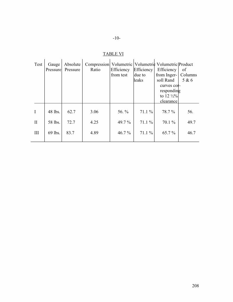
208
-10-
TABLE VI Test Gauge Absolute Compression Volumetric Volumetric Volumetric Product Pressure Pressure Ratio Efficiency Efficiency Efficiency of from test due to from Inger- Columns leaks soll Rand 5 & 6 curves cor- responding to 12 ½% clearance I 48 lbs. 62.7 3.06 56. % 71.1 % 78.7 % 56. II 58 lbs. 72.7 4.25 49.7 % 71.1 % 70.1 % 49.7 III 69 lbs. 83.7 4.89 46.7 % 71.1 % 65.7 % 46.7

209
-11-
VI – DETAILED CALCULATIONS FOR TEMPERATURE-ENTROPY DIAGRAM
Calculation #1
WET COMPRESSION CYCLE BETWEEN 20° and 80° F.
After compression at 80° Fah.
Gauge pressure = 45.2 lbs. per sq. in.
Total heat = H = 182 B.t.u.
Entropy = S = .3393
If the compression is adiabatic, the entropy must
have been the same before compression as afterward.
Therefore, before compression at 20° Fah.
S = .3393
This requires that the quality be,
X = .935
Total heat = H = 162.4
Volume = 4.72 × quality = 4.4132
After condensation at 80°
Total heat = H = 19
Entropy = S = .0372
After expanding through nozzle with constant heat
content, the temperature drops to 20°
Total heat = H = 19
This requires that the quality should be .1341.
The refrigerating effect is equal to the difference
of the total heat before compression and after expansion, or
162.4 – 19 = 143.4
Refrigerating effect per cu. ft. = 143.4 / 4.4132 = 32.5
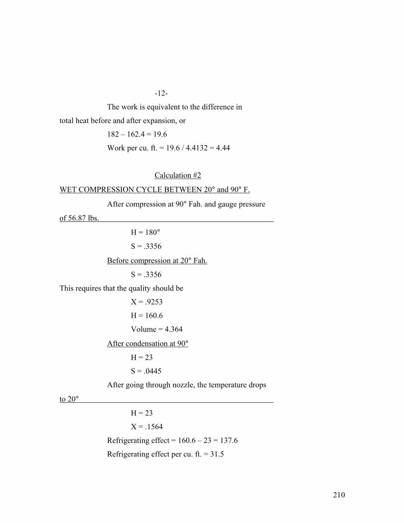
210
-12-
The work is equivalent to the difference in
total heat before and after expansion, or
182 – 162.4 = 19.6
Work per cu. ft. = 19.6 / 4.4132 = 4.44
Calculation #2
WET COMPRESSION CYCLE BETWEEN 20° and 90° F.
After compression at 90° Fah. and gauge pressure
of 56.87 lbs.
H = 180°
S = .3356
Before compression at 20° Fah.
S = .3356
This requires that the quality should be
X = .9253
H = 160.6
Volume = 4.364
After condensation at 90°
H = 23
S = .0445
After going through nozzle, the temperature drops
to 20°
H = 23
X = .1564
Refrigerating effect = 160.6 – 23 = 137.6
Refrigerating effect per cu. ft. = 31.5
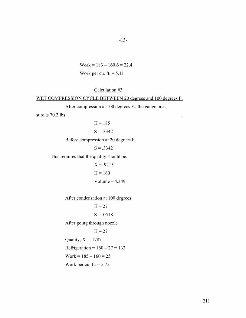
211
-13-
Work = 183 – 160.6 = 22.4
Work per cu. ft. = 5.11
Calculation #3
WET COMPRESSION CYCLE BETWEEN 20 degrees and 100 degrees F.
After compression at 100 degrees F., the gauge pres-
sure is 70.2 lbs. .
H = 185
S = .3342
Before compression at 20 degrees F.
S = .3342
This requires that the quality should be.
X = .9215
H = 160
Volume – 4.349
After condensation at 100 degrees
H = 27
S = .0518
After going through nozzle
H = 27
Quality, X = .1787
Refrigeration = 160 – 27 = 133
Work = 185 – 160 = 25
Work per cu. ft. = 5.75

212
January 16, 1924
APPENDIX # 8-B
AN EFFORT TO EXPLAIN THE LOW VOLUMETRIC AND
MECHANICAL EFFICIENCY OF THE OC-2 FORM H MACHINE
*************
EDITOR’s note: diagrams or drawings referenced are too faded to be included
Tests made on the ¾" stroke by 1-1/8"
diameter machine. If there are 1-1/2 thousandths clearance
in the end of the cylinder, the total clearance volume, ne-
glecting suction and discharge ports, would be 2.26%. How-
ever, the clearance between the piston and the end of the
cylinder is likely to be more than 1-1/2 thousandths, and we
have, therefore, assumed a total clearance volume of 4%.
With a 26° brine temperature, the absorp-
tion from the brine tank was 795 B.t.u. The probable leakage
up the expansion and suction tubes may have been 14 B.t.u.,
making a total refrigerating effect of 809 B.t.u.
In the Evaporator- P¹ = 16.9 lbs. absolute
T¹ = 19.36° Fahrenheit
H¹ = 184.66 B.t.u. per lb.
S¹ = .398
V¹ = 4.6 cu. Ft. per lb.
Inside the Cylinder- The walls of the cylinders are probably
around 150°F. (This will be checked by future tests.) The
vapor pressure of the oil at 150° F. is approximately 4.28 ice.
Since the total suction pressure is 16.9 lbs., the partial

213
-2-
pressure of the refrigerant would be 12.62 lbs. At the end
of the suction stroke, the cylinder is therefore filled with
vapor under the following conditions.
P2 = 12.62 lbs.
T2 = 150° F.
H2 = 208 B.t.u.
S2 = .445
V2 = 7.4 cu. Ft. per lb.
At the End of Compression- The condenser pressure is 106.7 lbs. absolute,
and there is a probable drop in the discharge valves of 13.3
lbs. Therefore, at the end of compression the vapor in the
cylinder is under the following conditions.
P3 = 120 lbs.
T3 = 355° F.
H3 = 250 B.t.u.
S3 = .445
V3 = 1.2 cu. Ft. per lb.
Re-expansion in Clearance- Four percent of this re-expands, and after re-
expansion the conditions are:
P4 = 12.62 lbs.
T4 = 150°F.
H4 = 208 B.t.u.
S4 = .445
V4 = 7.4 cu. ft. per lb.

214
-3-
It will be noted that this 4% expands from
a volume of 1.2 cu. ft. per lb. to a volume of 7.4 cu. ft.
per lb. Therefore, the volume has increased from 4% to 24.7%.
This is equivalent to a volumetric efficiency of 75.3% due to
re-expansion. There was another volumetric efficiency due to
the fact that the volume in the expansion coils was 4.6, where-
as the rise in temperature and reduction in pressure when enter-
ing the cylinder increased on volume per lb. to 7.4. This re-
presented a volumetric efficiency of 62.3%. The overall
volumetric efficiency would be the product of these two, or
46.7%.
Refrigerating Capacity- If the gas is condensed at 106.7 lbs. and
116° Fahrenheit, the total heat per pound of the liquid will be
51 B.t.u. This will not change going through the expansion
valve. The refrigerating capacity is, therefore, equal to,
184.66 – 51 = 133.66 B.t.u. per lb.
Since the machine did 809 B.t.u. per hour, it must circulate
6.05 lbs. per hour, with an apparent volume of 4.6 cu. ft. per
lb. There must, therefore, be sucked out of the evaporator
27.7 cu. ft. per hour which, with a volumetric efficiency of
46.7% and total displacement of the compressor of 59.5 cu. ft.
per hour, exactly corresponds to a two cylinder, single acting
compressor, 3/4" stroke by 1-1/8" diameter, running at 1150
r.p.u.
Work per Pound- The work per pound is the difference between

215
-4-
H3 and H2, is we neglect the work of re-expansion: this gives
42 B.t.u. The coefficient of performance is the refrigerating
effect divided by work, or
133.66 = 3.18 42
Work required per B.t.u. = 1 3.18 B.t.u.
Energy is watt-hours per B.t.u. = 1 = .09 watts per 3.18 × 3.414
The motor takes .406 watts per B.t.u. The
motor efficiency is 46.7%. Therefore, the motor output is
.190 watts. The compressor mechanical efficiency must be,
.09 / .406 = 47.4%
The overall electrical and mechanical efficiency is,
.09 / .406 = 22.%

216
-5-
While at Fort Wayne, I calculated the clear-
ance volumes of the standard 1" diameter by 3/4"stroke oscil-
lating cylinder compressor.
Drawing H-105455 shows the suction part of the
machine. The dotted line is the outline of the hole at the in-
side of the cylinder wall, whereas the heavy line is the outline
of the hole at the valve seat. The area at the valve seat is
about .04496 sq. in. and at the inner wall is .0611 sq. in. The
average area is, therefore, .05303. The depth through the cylin-
der is .187". The volume of the suction part is therefore .00994
cu. in.
Drawing H-105456 shows the outline of the dis-
charge valve at the inside of the cylinder wall. It had an area
of .0653 sq. in. The discharge valve at the outside is 1/8"
diameter and has an area of .049 sq. in. This makes an average
area of .05715 sq. in. The depth is .206"; the volume of the
discharge port is, therefore, .0118 cu. in.
There is a groove in the cylinder head, the
volume of which may be approximated by that of a triangular pyra-
mid, 1/32" altitude of base by, .1375 width of base by .625
height = 6.7 × 10⁻⁴ cu. in. A more accurate calculation by an-
other method shown 6.1 × 10⁻⁴ cu. in.
SUMMARY OF CLEARANCE VOLUME Volume of suction valve .00994 cu. in. Volume of discharge valve .01180 " " Volume of groove in cylinder head .00061 " " Volume of clearance between piston and end of cylinder = π/4x(1)²x.0015⁄ .00118 " " Total clearance volume .02353 cu. in. ⁄ The clearance between the piston and the end of the cylinder is probably, in a great many cases, considerably more than 1 ½ thousandths, as assumed.

217
-6- Total volume = π/4 × .75 = .59 cu. in.
Percent clearance volume = .02353 / .59 × 100 = 4%
The 3/4" stroke by 1 1/8" diameter cylinder is the same as the 1" diameter cylinder, except bored at 1/8" bigger diameter. The ports are, therefore, 1/16" shallower. The volume can therefore, be found by proportion from the fore- going. Volume of suction valve .00661 cu. in. Volume of discharge port .00824 " " Volume of groove (same as before) .00061 " " Volume in end of cylinder = π / 4 × (1-1/8)² × .0015 ⁄ .0015 " " Total clearance volume .01696 cu. in. Total volume = .75 cu. in. Percent clearance volume = 2.26% DROP THROUGH SUCTION VALVE Drawing H-105457 shows the area of the suction
valve with the cylinder at various angular positions.
Curve H-105458 was prepared by counting the
squares on drawing H-105457.
Drawing H-105459 shows the calculated distance
of the piston from the head and, plotted against the crank
angle. The solid line shows calculated values and the dotted
line show Mr. Orr’s measurements.
The full line on drawing H-105460 shows the
theoretical valve opening in inches. The circles show Mr. Orr’s
measurements.
⁄ The clearance between the piston and the end of the cylinder
is probably, in a great many cases, considerably more than
1 ½ thousandths, as assumed.
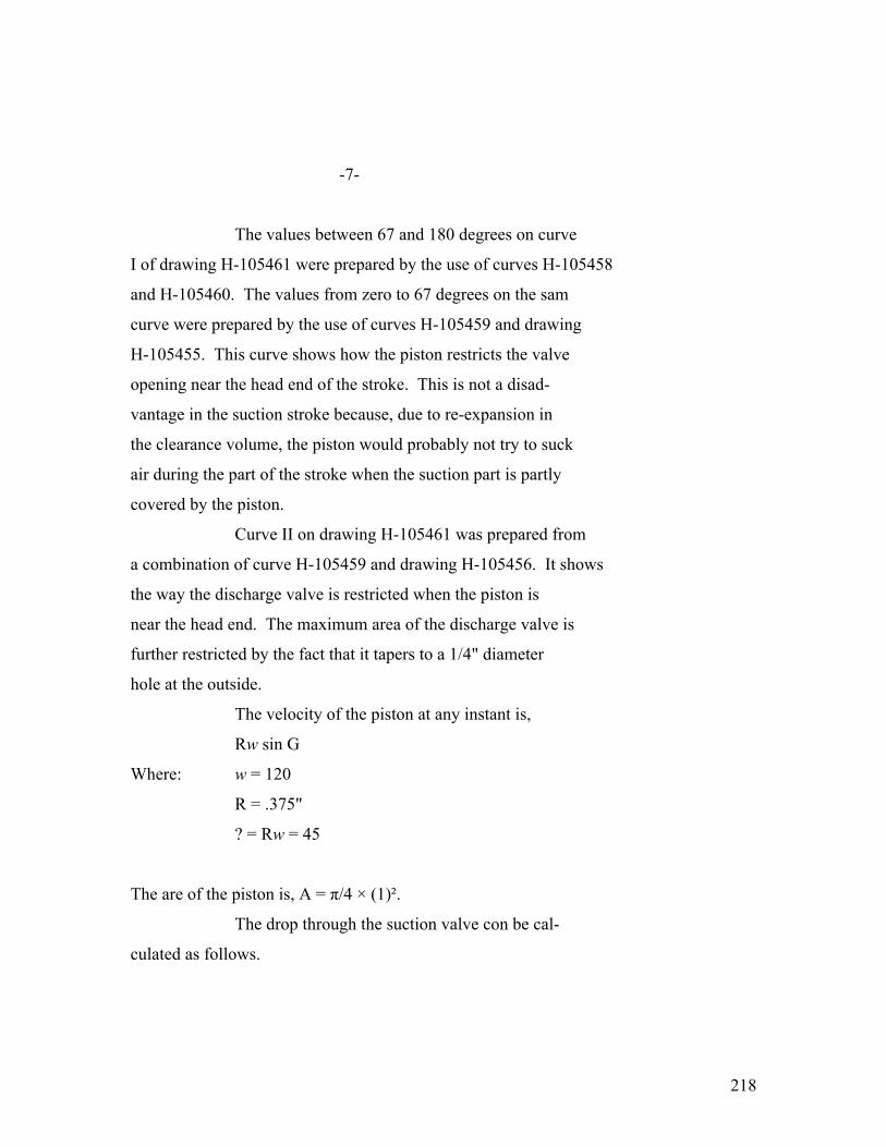
218
-7-
The values between 67 and 180 degrees on curve
I of drawing H-105461 were prepared by the use of curves H-105458
and H-105460. The values from zero to 67 degrees on the sam
curve were prepared by the use of curves H-105459 and drawing
H-105455. This curve shows how the piston restricts the valve
opening near the head end of the stroke. This is not a disad-
vantage in the suction stroke because, due to re-expansion in
the clearance volume, the piston would probably not try to suck
air during the part of the stroke when the suction part is partly
covered by the piston.
Curve II on drawing H-105461 was prepared from
a combination of curve H-105459 and drawing H-105456. It shows
the way the discharge valve is restricted when the piston is
near the head end. The maximum area of the discharge valve is
further restricted by the fact that it tapers to a 1/4" diameter
hole at the outside.
The velocity of the piston at any instant is,
Rw sin G
Where: w = 120
R = .375"
? = Rw = 45
The are of the piston is, A = π/4 × (1)².
The drop through the suction valve con be cal-
culated as follows.
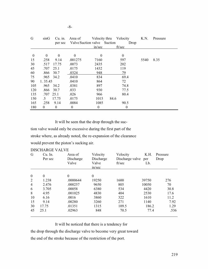
219
-8-
G sinG Cu. in. Area of Velocity thru Velocity K.N. Pressure per sec Valve Suction valve Suction Drop in/sec ft/sec 0 0 0 0 0 0 15 .258 9.14 .001275 7160 597 5540 8.35 30 .517 17.75 .0073 2435 202 45 .707 25.1 .0175 1432 119 60 .866 30.7 .0324 948 79 75 .965 34.2 .0410 834 69.4 90 1. 35.45 .0410 864 72 105 .965 34.2 .0381 897 74.8 120 .866 30.7 .033 930 77.5 135 .707 25.1 .026 966 80.4 150 .5 17.75 .0175 1015 84.6 165 .258 9.14 .0084 1085 90.5 180 0 0 0 0 0 It will be seen that the drop through the suc-
tion valve would only be excessive during the first part of the
stroke where, as already noted, the re-expansion of the clearance
would prevent the piston’s sucking air.
DISCHARGE VALVE G Cu. In. Area of Velocity Velocity K.H. Pressure Per sec Discharge Discharge Discharge valve per Drop Valve Valve ft/sec Lb. in/sec 0 0 0 0 2 1.238 .0000644 19250 1600 39750 276 4 2.476 .000257 9650 805 10050 70 6 3.705 .00058 6380 534 4420 30.8 8 4.95 .001025 4830 404 2530 17.6 10 6.16 .0016 3860 322 1610 11.2 15 9.14 .00280 3260 271 1140 7.92 30 17.75 .01351 1315 109.5 186.2 1.29 45 25.1 .02963 848 70.5 77.4 .536 It will be noticed that there is a tendency for
the drop through the discharge valve to become very great toward
the end of the stroke because of the restriction of the port.
220
-9-
The values of pressure drop shown are imaginary because before
the pressure rose to these high valves the air would compress
in the clearance volume.
DISCHARGE VALVE SPRING It took ¼ lb. spring balance to raise the
discharge valve spring. The discharge valve is a ¼" diameter
hole, having an area of .0491 sq. in. Therefore, a pressure of
at least 5.08 lbs. per sq. in. would be required to raise the
valve.
The spring of the discharge valve is tuned
three and one-half tones below Middle C. Middle C has 258.5
beats per second. A note three and one-half tones below Middle
C would have 211 beats per second. It would take half a bear
for the valve to rise and fall; therefore, it seems likely that
when the pressure risen sufficiently to open the valve, it will
open, the pressure will equalize, and the valve will tend to
fall again, receding in perhaps 1/422 seconds.
The main crank moves about eight degrees in
this time. It seems likely that the discharge valve will pro0
bably oscillate two or three times at each opening, until the
pressure drop due to the restriction will hold it open at the
end of the stroke.
Curve H-105463 shows the cylinder volume, in-
cluding the clearance volume, for different crank angles measured
from the head end position.
Curve H-105462 shows the approximate pressure
corresponding to various specific volumes.
221
TESTS ON THE OC-2 FORM “H” MACHINE #10053. WITH 1 1/8" DIAMETER BY 3/4" STROKE OSCIL- LATING CYLINDERS.
Schenectady, Feb. 2, 1924.
Mr. Robert Steck, Farm Power & Lighting Engr. Dept., Fort Wayne Works. Dear Mr. Stock: I have gone over Test #2 and Test #5 which were attached to your letter of January 26th. I made curve H-105480 for my own use, giving the calibration of brine tank #46. I believe that it is quite important that this calibration be checked by maintaining various temperatures with an electric heater. By this time, you will have received a report from me, showing the calcula- tions on the heat flow through the 4" of cork insulation in the Odin box under transient conditions. These calculations on the Odin show the type of error which we ran the chance of by our old-fashioned method of testing. I wish you would send me a complete specifica- tion of our brine tank, giving the dimensions and the materials. It may be possible to set up a set of equations from which the true amount of refrigeration can be calculated from these tran- sient runs. On the other hand, to use theoretical equations at all, it is necessary to know the exact temperature conditions in the cork before starting a run. It is my understanding that at present Mr. Orr heats up the inside of the brine tank rapidly with an electric heater after each refrigeration test. The re- sult is that perhaps in the middle of the wall, the work is still at a low temperature, whereas the outside is at room temperature and the inside has also been heated up to room temperature. A run started with this distribution of temperature would probably give entirely different results from a run started with everything equalized. I notice in going over the tests on the refri- gerating machine, that you have started the runs at 32°. We are all agreed that the end points of these runs are very inaccurate
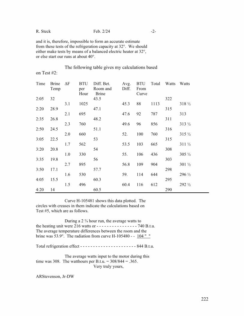
222
R. Steck Feb. 2/24 -2- and it is, therefore, impossible to form an accurate estimate from these tests of the refrigeration capacity at 32°. We should either make tests by means of a balanced electric heater at 32°, or else start our runs at about 40°. The following table gives my calculations based on Test #2: Time Brine ΔF BTU Diff. Bet. Avg. BTU Total Watts Watts Temp per Room and Diff. From Hour Brine Curve 2:05 32 43.5 322
3.1 1025 45.3 88 1113 318 ½ 2:20 28.9 47.1 315 2.1 695 47.6 92 787 313 2:35 26.8 48.2 311 2.3 760 49.6 96 856 313 ½ 2:50 24.5 51.1 316 2.0 660 52. 100 760 315 ½ 3:05 22.5 53 315 1.7 562 53.5 103 665 311 ½ 3:20 20.8 54 308 1.0 330 55. 106 436 305 ½ 3:35 19.8 56 303 2.7 895 56.8 109 904 301 ½ 3:50 17.1 57.7 298 1.6 530 59. 114 644 296 ½ 4:05 15.5 60.3 295 1.5 496 60.4 116 612 292 ½ 4:20 14 60.5 290 Curve H-105481 shows this data plotted. The circles with creases in them indicate the calculations based on Test #5, which are as follows. During a 2 ¾ hour run, the average watts to the heating unit were 216 watts or - - - - - - - - - - - - - - - - 740 B.t.u. The average temperature differences between the room and the brine was 53.9°. The radiation from curve H-105480 - - 104 " " Total refrigeration effect - - - - - - - - - - - - - - - - - - - - - - 844 B.t.u. The average watts input to the motor during this time was 308. The watthours per B.t.u. = 308/844 = .365. Very truly yours, ARStevenson, Jr-DW

223
APPENDIX #9
DISCUSSION OF THE POSSIBLE REDESIGN OF THE
FORT WAYNE TYPE OC-2 MACHINE FOR AIR COOLING
******************************
1. The condenser at present consists of a
copper tube carrying water through the gas chamber. This
tube is 12 ft. 3 in. long, and it had an outside diameter
of 5/8".
Let us assume that this same pipe is
placed out in the air and the gas piped through it.
The total heat transfer required is about
2000 B.t.u. per hour, or 585 watts.
This is very conservative because, as was
shown in appendix # , “Analysis of Tests on the Type
OC-2 Machine”, although 2000 B.t.u. per hour was absorbed
by the cooling water, only 1380 B.t.u. of this was absorbed
in the condenser and the rest was either given off in the
water jacket or dissipated directly from the case.
Mr. Chester Rice has given me a formula
for the convection of heat from cylinders.
Wc = .0067 D¾ L P½ Tavg .754
Tamb .877 ∆ t Let, D = 5/8" = 1.58 cm.
L = 12' 3" = 357 cm.
P = 1
224
-2-
Tamb = (460 + 70) ÷ 1.8 = 530/1.8 = 295° K.
Assume ∆ t = 10 degrees
Tavg = 300° K.
Substituting in the formula,
Wc = 17.85 watts.
The formula for radiation of heat is as
follows: 4 4 Wr = 5.7 × A × e [( T1 /1000 ) – ( T2 /1000 )]
A = 1870 sq. cm.
c = 1 (I assume the pipe can have a black furnace.)
T2 = 295
T1 = 305 3 -3
Wr = 5.7 × 1.87 × 10 × 1.08 × 10 = 11.5 watts
With a 10° Centigrade rise (18° Fahrenheit
rise), we have calculated that a length of pipe 12 ft. 3 in.
long will dissipate 17.85 watts through convection and
11.5 watts through radiation, making a total of 29.35 watts.

225
-3-
In order to dissipate 2000 B.t.u. per hour (585 watts), a
Length of pipe twenty times as long would be required, or
245 feet.#
I notice that the present condenser coil,
12 ft. 3 in. long, has a material charge of 89 cents and a
labor charge of 20 cents. Assuming that both the material
and the labor together are in direct proportion to the
length, a coil 245 ft. long would have a,
Material charge - - - - - - - - - - - - - $ 17.80
Labor - - - - - - - - - - - - - - - - - - - - 4.00
140% Labor overhead - - - - - - - - - 5.60
Additional factory cost - - - - - - - - $ 27.40
From this could be subtracted about $7.40, covering the
various parts which are now included for the automatic con-
trol of water. Therefore, the condenser could be changed
for air cooling at an additional factory cost of about
$20.00.
I assume that the motor housing could be
cast with fins for about the same price that the present
water jacket is included.
___________
Foot-note (#) : These calculations are made on the basis of still air, and it is possible that if this pipe is coiled in the form of a chimney, less would be required. The Kelvinator has 20 turns of pipe and I imagine the rectangles are about 35" × 20". This corresponds to about 185 ft. of pipe. The Kelvinator probably does not rise more than 18°F., due to the chimney action and the windage from the motor, etc.

226
-4-
ECONOMY OF AIR COOLED OPERATION.
Having built the condenser for an 18 degree
rise, on a 70 degree day this machine would run with a con-
denser temperature of 38°F.
In the appendix on the type OC-2 water
cooled machine, it was calculated from the pressure that the
condenser temperature was 82 ½ degrees.
From a theoretical Carnot cycle standpoint,
a machine operating between 88° and 21° would require 9 per-
cent more power than a machine operating between 82 ½°
and 21°. This is also consistent with the tests shown on
H-99373.
In the appendix on the factors determining
the proper rating for ice machines, it was pointed out that
Mr. Waters’ type OC-2 water cooled machine required on the
average 1.45 KW-hours per day. But, this was with the older
slow speed compressor. The new high speed compressor re-
quires .315 watt-hours per B.t.u., which is
.315/.28 = 112%
twelve percent more than the old machine under the same con-
ditions. It would, therefore, have taken about 1.62 KW-hours
per day. At five cents per KW-hour, the power bill would have

227
-5-
been about $14.50 for six months. At $1.00 per thousand
cubic feet, the water would have cost 86 cents for the same
period.
Nine percent of $14.50 is $1.30. Therefore,
The power bill for the air cooled machine would probably be
$1.30 more in six months. Of course, the 86 cents water
bill would be saved.
I would point out, however, that this com-
prison is not really fair to the air cooled machine because
the water here in Schenectady is very cold, even in the
hottest part of summer it never gets above 59°.
The actual hottest temperature of the water
supply during the summer for twenty-one cities in New York,
Georgia, and Texas, averages about 70°, and ranges anywhere
from 50° to 90°.
For the extreme case, let us assume that the
air temperature is 110° and the water temperature is 90°.
On a ninety degree day, about 50 percent more
refrigeration would be required.
On June 15, 1923, Mr. Crane made a test on
machine #10045, with the water leaving at 123 degrees. The
condenser pressure was 90 lbs. This corresponds to about
102°. With the brine tank at 19.6 degrees, the power input
was 332 watts and the machine was absorbing heat at the rate
of 716.9 B.t.u. per hour. This is at the rate of 120 lbs.

228
-6-
of ice a day and 8 KW-hours per day. The energy input is
.465 watt-hours per B.t.u. This is about 47 percent greater
than the other test under normal conditions.
Due to the 82 degree difference in tempera-
ture instead of a 61.5 degree difference, we would theore-
tically expect about 35 percent increase in power. The other
12 percent may be due to the fact that the volumetric effi-
ciency might have been worse at these higher pressures.
The power bill for six months at 3.6 KW-hours
a day with a five cent rate would be about $33.00.
The amount of heat taken up by the cooling
water and radiation must have been 716.9 B.t.u., plus 1100,
or 1816.9 B.t.u.
About 850 of this B.t.u. must have been in
the condenser. The drop would, therefore, be,
14 ¼ × 850/1380 = 8.8 degrees.
The average temperature of the condensing
water must have been about 102 – 8.8 = 93.2°F.
If four gallons of water per hour are used,
the rise in the condenser would be 34.8 degrees; the water
entering would be 93.2 – 17.4 = 75.8, and leaving would be
110.6.
The heat taken from the water jacket would
be about half of 967 or 482 B.t.u. The rise would be about

229
-7-
14.6 degrees. This would make the outgoing water 125.2° F. ,
which checks fairly well with the value of 123°F.
In order to maintain a condenser temperature
of 102° F. with water entering at 90°, it would be necessary
to use,
4 × 17.4/3.2 = 22 gallons of water per hour.
The machine would run 46 percent of the
time so that the daily water consumption would be 245 gallons
per day, or 32.5 cu. Ft. At $1.00 per thousand cubic feet,
the water bill in six months would be $6.00.
The total cost of operation would be $39.00
for the six months.
The above water bill is unreasonable.
Suppose that we assume the rise to be 30°.
Then, the average temperature would be 105 degrees, and the
condenser temperature would be 115 degrees.
It can be seen from curve H-99373 that the
capacity of the machine would be 689 B.t.u. , with a corres-
ponding input of 340 watts.
The 340 watts input represents 1160 B.t.u.
The total B.t.u. which must be taken care of by the cooling water is the sum of the equi- valent of the watts input and the refri- gerating effect, or - - - - - - - - - - - - - - - 1849 " The B.t.u. given up in cooling and liquefying The sulphur dioxide is - - - - - - - - - - - - 840 " Difference - - - - - - - - - - 1009 B.t.u.

230
-8- It is likely that half this difference is
radiated from the case and the other half taken up by the
cooling water. The requirements for cooling water would be,
Condenser - - - - - - - - - - - - - 689 B.t.u.
Water jacket- - - - - - - - - - - - 504 " Total - - - - - - 1193 B.t.u.
If the cooling water is allowed up to rise
thirty degrees, 4 ¾ gallons per hour will be required,
The machine would have to run 46 percent
of the time. Therefore, the daily consumption would be
3.76 KW-hours electrical energy and 48 gallons, or 6.4 ou. Ft.
of water.
The six months power bill would be - - - - - - - -$ 34.20 The six months water bill would be - - - - - - - - 1.16 Total for six months’ bill - - $ 35.36 The air cooled machine operating in a 110
degree room would have a condenser temperature of about
130 degrees.
A condenser temperature of 130 degrees
would correspond to about 126 lbs. per square inch.
From H-99373 it can be seen that with
130 degrees condenser temperature, .6 watt-hours per B.t.u.
231
-9-
or about 4 ½ KW-hours per day would be required. # There-
fore, the six months’ power bill would be $41.00 as against
$35.36. If these extreme conditions lasted for six months,
the water cooled machine would show a saving of $4.64.
These figures for the 90 degree day, of
course, should not be applied to so long a period as six
months because there is no place in the country where such
temperatures would last for six months.
I would also point out that the amount of
water used by the type OC-2 machine is very much less than
the Frigidaire. The records at Mr. Waters’ show a maximum
of 7.85 cu. Ft. per day in July, whereas the corresponding
size Frigidaire machine is advertised as taking 20 to 30
_________________
Foot-note (#): On May 23, 1923, Mr. Crane ran a test at 125 lbs. condenser pressure which showed that 471 watt-hours were required to produce 480 B.t.u. This is at the rate of .98 watt-hours per B.t.u. This is 58 percent more power than we figured from the other tests. It would seem to in- dicate that at these high temperatures and pressures the oil seals on the compressor pistons and valves ceased to function properly. However, I do not feel that this test is reliable because it was run with very small quantities of cold water instead of a lot of warm water. In fact, the water was turned on and off continually in an attempt to adjust the temperature. If this test is correct, then if the room temperature was 110 degrees Fahrenheit for six months, the power bill for the air cooled machine would be 1.63 times the water cooled power bill. It seems obvious from curve H-99373 that this test is wrong.
232
-10-
cu. Ft. per day. Of course, if the machine took 30 cu. ft.
of water, this water charge would be $1.87 multiplied by 30,
divided by 7.85, which would be $7.15, which would more
than balance the power bill of the air cooled machine unless
Mr. Crane’s test at 126 lbs. is correct.
In redesigning this machine for air cooling it may
be necessary to increase the cylinder sizes in order to
maintain a capacity of approximately equivalent to the
melting of 100 pounds of ice per days, which rating would be
required by the Balsa box on a 90° day.
(Editors note: Curve H-99373 faded beyond recognition )
233
APPENDIX #10.
ABSORPTION MACHINES
****************
The following theoretical example is
worked out for comparison with the calculations made in
appendices Nos. 11, for compression machines. The
temperature of the expansion coils is assumed to be 21°F.,
and the temperature in the condenser and generator which can
be obtained by means of cooling water is assumed to be
82 ½ °F. The machine will be assumed to operate with
ammonia and water.
The system will be very simple, consist-
ing only of a generator and condenser, an expansion valve,
and expansion coils. The generator will also be used as
the absorber.
The concentration in the absorber can be
obtained from the formula,
Tsat/Tsol = .0047x + .655 (1)
Tsat = 21 + 459.6 = 480.6
Tsol = 82 ½ + 459.6 = 542.1
? x = 48.8%
The condenser will also run at 82.5 degrees
The saturation pressure is 159.65 lbs/in²
absolute.
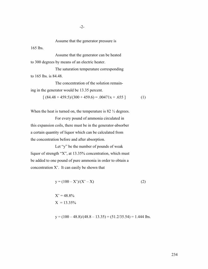
234
-2-
Assume that the generator pressure is
165 lbs.
Assume that the generator can be heated
to 300 degrees by means of an electric heater.
The saturation temperature corresponding
to 165 lbs. is 84.48.
The concentration of the solution remain-
ing in the generator would be 13.35 percent.
[ (84.48 + 459.5)/(300 + 459.6) = .00471x + .655 ] (1)
When the heat is turned on, the temperature is 82 ½ degrees.
For every pound of ammonia circulated in
this expansion coils, there must be in the generator-absorber
a certain quantity of liquor which can be calculated from
the concentration before and after absorption.
Let “y” be the number of pounds of weak
liquor of strength “X”, at 13.35% concentration, which must
be added to one pound of pure ammonia in order to obtain a
concentration X’. It can easily be shown that
y = (100 – X’)/(X’ – X) (2)
X’ = 48.8%
X = 13.35%
y = (100 – 48.8)/(48.8 – 13.35) = (51.2/35.54) = 1.444 lbs.

235
-3-
Step #1 – Heating from 82 ½° to 165 lbs. pressure.
At the beginning of the heating period,
there is in the generator,
Liquor at ( 48.8% concentration ) 2.444 lbs.
( t = 82 ½° F. )
( p = 49 ½ lbs. )
The specific gravity of this liquor at
60 degrees is given by the formula,
s60 - 1 - 4.3/1000 [ x - x²/100 + x³/10,000 ] (3)
x = 48.8%
s60 = 1 - .157 = .843
The specific gravity at some other temper-
ature can be obtained,
s60 = st + .003(t – 60)(1 – st) (4)
s82 ½ = .831
The volume of this 2.444 lbs. is, therefore,
.047 cu. Ft., 81 cu. Inches.
It probably would not be practical to
attempt to make the generator just this volume.
Suppose the generator is 100 cubic inches.
This leave 19 cu. Inches = .011 cu. Ft. for vapor.
The vapor pressure of the steam would be,
Vapor pressure x psat 1700 – 17 I/1700 + x
At 82 ½ degrees,
psat = .5483

236
-4-
The ammonia vapor pressure would be,
49.5 - .5483 = 48.9517
Volume of 1 lb. of ammonia vapor, 48.9517 lbs.
and 82 ½° = 6.723 cu. Ft.
Heat content per pound of ammonia = 576.26.
Volume 1 lb. of steam vapor, .5483 lbs. and
82 ½° = 587.51 cu. Ft.
Heat content per pound of steam – 1095 B.t.u.
Therefore in .011 cu. Ft., there would be
.00164 lbs. of ammonia vapor and .0000187 lbs. of steam.
We will neglect these.

237
-5-
Now, assume that the non-return valve from the
expansion coils is closed and the heat turned on.
It will also be assumed that there is
some liquid ammonia left in the condenser which will hold
up the condenser pressure.
Therefore, the non-return valve to the
condenser will not open until the pressure reaches 165 lbs.
The saturation temperature corresponding
to 165 lbs. is 84.48° ?.; the temperature to which the
48.8 percent concentrated solution must be heated in order
to get a pressure of 165 lbs. is given by the formula:
Tsat/Tsol = .00471X + .655
X = 48.8%
Tsat = 84.48 + 459.6 = 544.08
Tsol = 544.08/.875 = 622 = 163.4 degrees
Let us see whether the concentration of
the solution could have changed during this heating.

238
-6-
The specific gravity of this liquor can
be calculated by equations (3) and (4).
Then, s162.4 = .722
The liquor, therefore, expands in volume
from .047 cu. Ft. to .054 cu. Ft. This only leaves .004
cu. Ft. for the vapors.
The vapor pressure of the steam can be
calculated from equation (5).
Pest? st 162.4° F. = 5.017
X = 48.8%
Vapor pressure = 5.017 – ((1700 - 17 × 48.8)/(1700 + 48.8)) = 2.48 lbs.
The ammonia pressure is,
165 – 2.48 = 162.52 lbs.
The volume of one pound of ammonia vapor at
162.52 lbs. and 162.4° F. = 2.2466 cu. Ft.
The volume of one pound of steam at 2.48 lbs.
and 162.4° F. = 149 cu. Ft.
Therefore, in .004 cu. Ft., there would be
.0018 lbs. of ammonia vapor and .000027 lbs. of water vapor.
Therefore, .00016 lbs. of ammonia must have
evaporated and .0000083 lbs. of water must have evaporated
from the liquor during this heating. These quantities are
so small that I believe then can be neglected.
The heat necessary to accomplish this
preliminary heating can be estimated as follows.
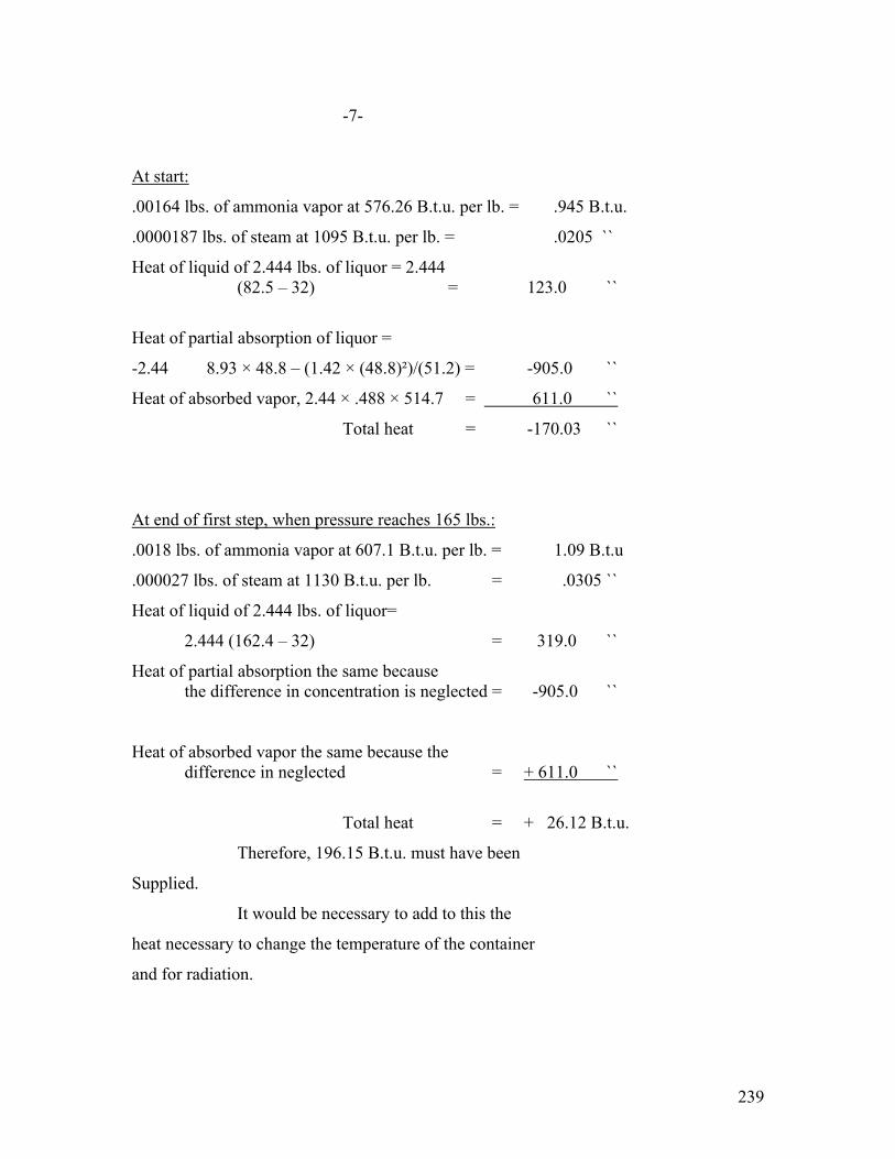
239
-7-
At start:
.00164 lbs. of ammonia vapor at 576.26 B.t.u. per lb. = .945 B.t.u.
.0000187 lbs. of steam at 1095 B.t.u. per lb. = .0205 ``
Heat of liquid of 2.444 lbs. of liquor = 2.444 (82.5 – 32) = 123.0 ``
Heat of partial absorption of liquor =
-2.44 8.93 × 48.8 – (1.42 × (48.8)²)/(51.2) = -905.0 ``
Heat of absorbed vapor, 2.44 × .488 × 514.7 = 611.0 ``
Total heat = -170.03 ``
At end of first step, when pressure reaches 165 lbs.:
.0018 lbs. of ammonia vapor at 607.1 B.t.u. per lb. = 1.09 B.t.u
.000027 lbs. of steam at 1130 B.t.u. per lb. = .0305 ``
Heat of liquid of 2.444 lbs. of liquor=
2.444 (162.4 – 32) = 319.0 ``
Heat of partial absorption the same because the difference in concentration is neglected = -905.0 ``
Heat of absorbed vapor the same because the difference in neglected = + 611.0 ``
Total heat = + 26.12 B.t.u.
Therefore, 196.15 B.t.u. must have been
Supplied.
It would be necessary to add to this the
heat necessary to change the temperature of the container
and for radiation.

240
-8-
Step #2 – Heating from 162.4° to 230°.
The next step in the process is a boiling
at a constant pressure of 165 lbs. , while the temperature
rises and the concentration decreases.
In order to accomplish this step accurately,
it would probably be necessary to split it up into five
degree intervals in order to determine the exact amount of
heat which leaves with the ammonia vapor.
In order to simplify this pressure, an inter-
mediate point at 230° and a final point at 300° will be cal-
culated and a curve drawn through the three points, including
the first point at 162.4°.
At 230° and 165 lbs. pressure, the concentration
can be determined by substitution in equation (1) as 28.6 percent.
The vapor pressure of the steam can be determined
by substitution in equation (5). The saturation pressure at
230° F. is 20.78 lbs.
The vapor pressure is, therefore, equal to
20.78 × ((1700 – 17 × 28.6)/(1700 + 28.6)) = 14.6 lbs.
The ammonia pressure is the difference between 165 lbs. and 14.6 lbs., or = 150.4 lbs. The specific volume of ammonia vapor at 150.4 lbs and 230° F. = 2.766 cu. Ft. The heat content is approximately 648.1 B.t.u.
The volume of one pound of steam at 14.6 lbs. and
230° is 27.84 cu. Ft. The heat content is approximately 1158 B.t.u.
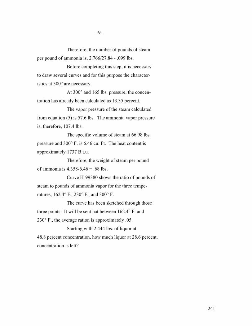
241
-9-
Therefore, the number of pounds of steam
per pound of ammonia is, 2.766/27.84 - .099 lbs.
Before completing this step, it is necessary
to draw several curves and for this purpose the character-
istics at 300° are necessary.
At 300° and 165 lbs. pressure, the concen-
tration has already been calculated as 13.35 percent.
The vapor pressure of the steam calculated
from equation (5) is 57.6 lbs. The ammonia vapor pressure
is, therefore, 107.4 lbs.
The specific volume of steam at 66.98 lbs.
pressure and 300° F. is 6.46 cu. Ft. The heat content is
approximately 1737 B.t.u.
Therefore, the weight of steam per pound
of ammonia is 4.358-6.46 = .68 lbs.
Curve H-99380 shows the ratio of pounds of
steam to pounds of ammonia vapor for the three tempe-
ratures, 162.4° F., 230° F., and 300° F.
The curve has been sketched through those
three points. It will be sent hat between 162.4° F. and
230° F., the average ration is approximately .05.
Starting with 2.444 lbs. of liquor at
48.8 percent concentration, how much liquor at 28.6 percent,
concentration is left?

242
-10-
Let, y = Number of pounds of ammonia that
are boiled over.
Then, .05 y = Number of pounds of water boiled over.
Lbs. of Ammonia Lbs. of Water
At Start 1.19 1.254
Loss y .05 y
At finish 1.19 – y 1.254 - .05 y
Concentration = .286 = 1.19 – y
1.19 – y + 1.254 - .05 y
Solving this, y = .7 lbs. ammonia.
.05 y = .035 lbs. water.
This leaves 1.709 lbs. of liquor.
The specific gravity of the liquor at
28.6 percent concentration and 230° can be determined from
equations (3) and (4) as .8. Therefore, the volume of
1.709 lbs. of liquor under these conditions is .0343 cu. Ft.
since the tank contains .058 cu. Ft., this leaves .0237 cu. Ft.
for vapor.
Since the specific volume of the ammonia
vapor is 2.766, there would be room for .00855 lbs. Since
the specific volume of the steam is 27.84 cu. Ft., there
would be room for .00085 lbs. of steam.
WEIGHT BALANCE FOR GENERATOR WHITE HEATING FROM 162.4°F.
To 230°F.
At 162.4°
Lbs. of liquor at 48.8% concentration 2.444 Lbs. of ammonia vapor .0018 Lbs. of steam .000027 Total 2.445827
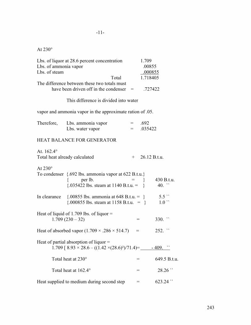
243
-11- At 230° Lbs. of liquor at 28.6 percent concentration 1.709 Lbs. of ammonia vapor .00855 Lbs. of steam .000855 Total 1.718405 The difference between these two totals must have been driven off in the condenser = .727422 This difference is divided into water vapor and ammonia vapor in the approximate ration of .05. Therefore, Lbs. ammonia vapor = .692 Lbs. water vapor = .035422 HEAT BALANCE FOR GENERATOR At. 162.4° Total heat already calculated + 26.12 B.t.u. At 230° To condenser {.692 lbs. ammonia vapor at 622 B.t.u.} { per lb. = } 430 B.t.u. {.035422 lbs. steam at 1140 B.t.u. = } 40. `` In clearance {.00855 lbs. ammonia at 648 B.t.u. = } 5.5 `` {.000855 lbs. steam at 1158 B.t.u. = } 1.0 `` Heat of liquid of 1.709 lbs. of liquor = 1.709 (230 – 32) = 330. `` Heat of absorbed vapor (1.709 × .286 × 514.7) = 252. `` Heat of partial absorption of liquor = 1.709 [ 8.93 × 28.6 – ((1.42 ×(28.6)²)/71.4)= - 409. `` Total heat at 230° = 649.5 B.t.u. Total heat at 162.4° = 28.26 `` Heat supplied to medium during second step = 623.24 ``
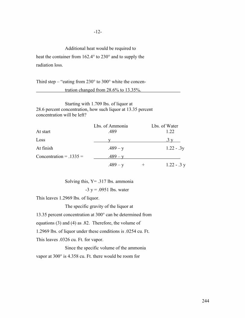
244
-12-
Additional heat would be required to
heat the container from 162.4° to 230° and to supply the
radiation loss.
Third step – “eating from 230° to 300° white the concen-
tration changed from 28.6% to 13.35%.
Starting with 1.709 lbs. of liquor at 28.6 percent concentration, how such liquor at 13.35 percent concentration will be left? Lbs. of Ammonia Lbs. of Water At start .489 1.22
Loss y .3 y
At finish .489 – y 1.22 - .3y
Concentration = .1335 = .489 – y
.489 – y + 1.22 - .3 y
Solving this, Y= .317 lbs. ammonia
-3 y = .0951 lbs. water
This leaves 1.2969 lbs. of liquor.
The specific gravity of the liquor at
13.35 percent concentration at 300° can be determined from
equations (3) and (4) as .82. Therefore, the volume of
1.2969 lbs. of liquor under these conditions is .0254 cu. Ft.
This leaves .0326 cu. Ft. for vapor.
Since the specific volume of the ammonia
vapor at 300° is 4.358 cu. Ft. there would be room for

245
-13-
.00148 lbs. Since the specific volume of the steam at 300°
is 6.64 cu. Ft., there would be room for .00505 lbs.
WEIGHT BALANCE FOR GENERATOR WHILE HEATING FROM 230° to 300°,
At 300°
Lbs. of liquor at 13.35% concentration 1.2969 Lbs. ammonia vapor .00748 Lbs. of steam .00505 Total 1.30943 At 203° Total 1.718405 Therefore, the difference must have been driven off into the condenser = .408975 This difference is divided into steam and
ammonia in the approximate ratio of .3, which is the average
of curve H-99380 between 230° and 300°.
Lbs. ammonia vapor = .314 Lbs. water vapor = .094975 HEAT BALANCE FOR GENERATOR At 230° Total heat of liquor and vapors remaining in generator = (649.5 – 470) = 179.5 At 300° To condenser .324 lbs. ammonia at 662 B.t.u. = 207. .094975 lbs. steam at 1360 B.t.u. = 129. In clearance .00748 lbs. ammonia at 692.4 = 5.2 .00505 lbs. steam at 1737 B.t.u - 8.75

246
-14- Heat of liquid of 1.2969 lbs. of liquor = 1.2969 (300 – 32) = 348 B.t.u. Heat absorbed vapor (1.2969 × .1335 × 514.7) = 89.2 Heat of partial absorption of liquor = 1.2969 [ 8.93 × 13.35 – (1.42 ×(13.35)²)/86.65) ]= -150.5
Total heat at 300° = 636.65 B.t.u. Total heat at 230° = 179.5 `` Heat which must be supplied = 457.15 Additional heat would be necessary to
heat the container from 230° to 300° and to supply the
radiation losses.
SUMMARY OF THE HEAT SUPPLIED TO THE GENERATOR.
First Step
B.t.u. consumed by medium 196.15
Second Step
B.t.u. consumed by medium 623.24 Third Step B.t.u. consumed by medium 457.15
Total = 1276.54 B.t.u.
Curve H-99381 has been drawn to show the
process of heating from 162.4° to 300°. The curves are all
drawn through three points, 162.4°, 230°, and 300°. The
curve for B.t.u. required has been increased above that re-
quired to heat the medium by 45 B.t.u., to raise the tempe-
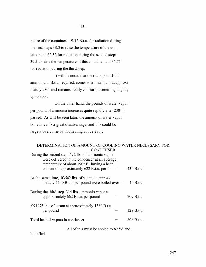
247
-15-
rature of the container. 19.12 B.t.u. for radiation during
the first steps 38.3 to raise the temperature of the con-
tainer and 62.32 for radiation during the second step:
39.5 to raise the temperature of this container and 35.71
for radiation during the third step.
It will be noted that the ratio, pounds of
ammonia to B.t.u. required, comes to a maximum at approxi-
mately 230° and remains nearly constant, decreasing slightly
up to 300°.
On the other hand, the pounds of water vapor
per pound of ammonia increases quite rapidly after 230° is
passed. As will be seen later, the amount of water vapor
boiled over is a great disadvantage, and this could be
largely overcome by not heating above 230°.
DETERMINATION OF AMOUNT OF COOLING WATER NECESSARY FOR CONDENSER
During the second step .692 lbs. of ammonia vapor were delivered to the condenser at an average temperature of about 190° F., having a heat content of approximately 622 B.t.u. per lb. = 430 B.t.u At the same time, .03542 lbs. of steam at approx- imately 1140 B.t.u. per pound were boiled over = 40 B.t.u During the third step .314 lbs. ammonia vapor at approximately 662 B.t.u. per pound = 207 B.t.u .094975 lbs. of steam at approximately 1360 B.t.u. per pound = 129 B.t.u. Total heat of vapors in condenser = 806 B.t.u. All of this must be cooled to 82 ½° and liquefied.

248
-16-
The possible concentration at 165 lbs.
pressure and 82.5° F. can be determined from equation (1)
as 77.3 percent.
After liquefying, there will be .130395 lbs.
of water which can take up .444 lbs. of ammonia vapor, making
.574395 lbs. of liquor at 77.3 percent concentration. This
leaves .556 lbs. of liquid ammonia.
Heat of liquid of .5744 lbs. of liquor = .5744 (82.5 – 32) = 29 Heat of absorbed vapor, (.5744 × .773 × 514.7) = 229 Heat of partial absorption of liquor = .5744 [8.93 × 77.3 – ((1.42 × (77.3)²)/22.7)] = -182 Heat of .556 lbs. of liquid ammonia = 31.6 Total heat of liquor and ammonia leaving condenser = 107.6 B.t.u. Heat entering condenser = 806.
Therefore, condenser must have removed – 698.0 B.t.u.
EXPANSION VALVE
In going through the expansion valve, the
total heat must remain constant or 179.6 B.t.u.
The conditions in the expansion coils are
21° F. and 49.28 lbs. pressure. The concentration which is
required under these conditions can be determined from
equation (1) as 73 percent. Therefore, .22 lbs. of ammonia
will be forced out of the solution. This leaves .3504 lbs.

249
-17-
of liquor at 73 percent concentration and .776 lbs. of
ammonia.
Heat of liquor of .3504 lbs. of liquor = .3504 (21 – 32) = -2.86 Heat of absorbed vapor, (.3504 × .773 × 514.7) - = 140. Heat of partial absorption = .3504 [(8.93 × 77.3) - ((1.42 × (77.3)²)/22.7)) =-111. Heat of liquid .776 lbs. of ammonia at 21° = -12.1 Total heat of liquids after passing through expansion valve = 14.04 B.t.u. Total heat should equal = 107.6 ``
Difference = 93.56 B.t.u.
Since the latent heat of ammonia at 21° is
552.2 B.t.u. per pound, .168 lbs. of ammonia must have been
vaporized in order to make up this difference.
There remains in the expansion coils, therefore,
Lbs. of liquor at 73 percent = .3504
Lbs. of ammonia vapor = .168
Lbs. of liquid ammonia = .608
The refrigerating effect, instead of cor-
responding to the evaporation of one pound of ammonia is re-
duced due to the presence of the water to only the equivalent
of .608 lbs. of ammonia. Therefore, per pound of ammonia is
circulated, there is only 552.2 × .608 = 335 B.t.u. refri-
gerating effect.

250
-18-
COOLING WATER NECESSARY FOR ABSORBER
The liquid and vapors left in the absorber
must be cooled from 300° to 82 ½°.
The heat content at 300° was = 300.65 B.t.u.
The liquor and vapor from the expansion coils has a heat content of 107.6 + 335 = 442.6 `` Total =743.25 B.t.u. After absorption, the heat content is =-170.03 `` Therefore, the cooling water must have removed 913.28 B.t.u. SUMMARY OF B.T.U. USED IN HEATING AND COOLING THE MEDIUM. In order to obtain a Lbs. of ammonia 1 lb refrigerating effect Circulated of 167 lbs. of ice in 24 hrs. 72 lbs. Heat required during 1276.54 B.t.u. 91,100 B.t.u. generating period Heat removed in con- 698.4 B.t.u. 50,000 B.t.u. denser by cooling water Refrigerating effect 335. B.t.u. 24,000 B.t.u. Heat removed in ab- 913.28 B.t.u. 65,600 B.t.u. sorber by cooling water
1611.54 1611.68
CHECK The foregoing table shows that in order to
equal the rating of the Fort Wayne type OC-2 machine, it would
be necessary to circulate 72 lbs. of ammonia in twenty-four hours.
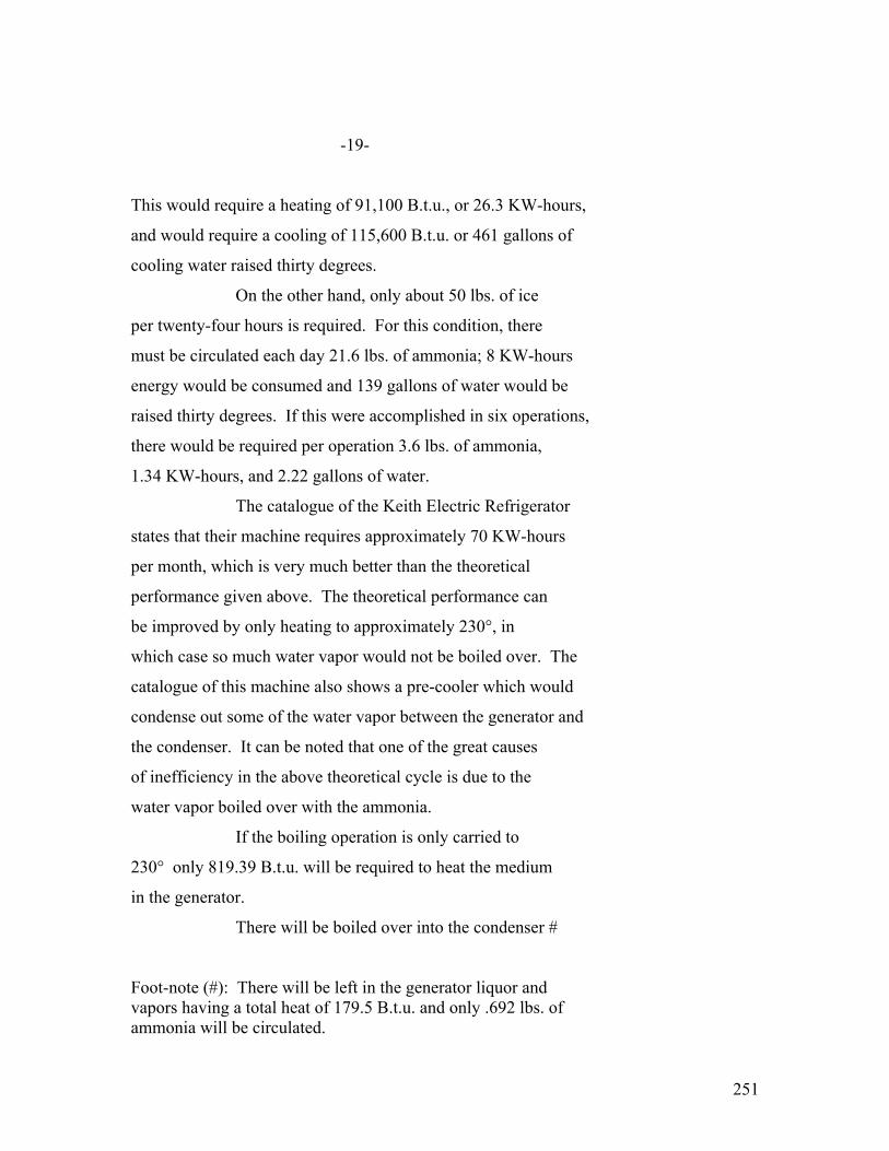
251
-19-
This would require a heating of 91,100 B.t.u., or 26.3 KW-hours,
and would require a cooling of 115,600 B.t.u. or 461 gallons of
cooling water raised thirty degrees.
On the other hand, only about 50 lbs. of ice
per twenty-four hours is required. For this condition, there
must be circulated each day 21.6 lbs. of ammonia; 8 KW-hours
energy would be consumed and 139 gallons of water would be
raised thirty degrees. If this were accomplished in six operations,
there would be required per operation 3.6 lbs. of ammonia,
1.34 KW-hours, and 2.22 gallons of water.
The catalogue of the Keith Electric Refrigerator
states that their machine requires approximately 70 KW-hours
per month, which is very much better than the theoretical
performance given above. The theoretical performance can
be improved by only heating to approximately 230°, in
which case so much water vapor would not be boiled over. The
catalogue of this machine also shows a pre-cooler which would
condense out some of the water vapor between the generator and
the condenser. It can be noted that one of the great causes
of inefficiency in the above theoretical cycle is due to the
water vapor boiled over with the ammonia.
If the boiling operation is only carried to
230° only 819.39 B.t.u. will be required to heat the medium
in the generator.
There will be boiled over into the condenser #
Foot-note (#): There will be left in the generator liquor and vapors having a total heat of 179.5 B.t.u. and only .692 lbs. of ammonia will be circulated.

252
-20-
.692 lbs. ammonia vapor at 622 B.t.u. = 430
.035422 lbs. steam at 1140 B.t.u. = 40
Total heat of vapors going to condenser = 470 B.t.u.
These vapors must be cooled to 82.5° and
liquefied.
The possible concentration is 77.3 percent.
After liquefaction, there will be .035422 lbs.
of water which can take up .12 lbs. of ammonia, making
.155422 lbs. of liquor at 77.3 percent concentration. This
leaves .572 lbs. of liquid ammonia.
Heat of liquid of .155422 lbs. of liquor at 82.5° =.55422 (82.5 – 32) = 7.9 B.t.u.
Heat of absorbed vapor, (.155422 × .773 × 514.7) = 62.0 ``
Heat of partial absorption of liquor =
.155422 [8.93 × 77.3 – ((1.42 × (77.3)²)/22.7)] = -49.4 ``
Heat of .572 lbs. of liquid ammonia = 32.5 ``
Total heat of liquids leaving condenser = 53.0 ``
Total heat of vapors entering condenser = 470.0 ``
Cooling water must absorb 417.0 B.t.u.
Going through the expansion valve, the
total heat stays constant.
At 21° F. and 49.28 lbs., the concentration
will be 73 percent.
Therefore, .025 lbs. of ammonia will be
forced out of the solution. This leaves .130422 lbs. of
liquor and .597 lbs. of ammonia.

253
-21-
Heat of .130422 lbs. of liquor = -1.07 B.t.u.
Heat of absorbed vapor = 52.1 ``
Heat of partial absorption = -41.4 ``
Heat of liquid of .597 lbs. of ammonia = - 9.3 ``
Total = 0.33 B.t.u.
Heat should equal + 53.00 ``
Heat corresponding to evaporation 52.67 B.t.u.
Therefore, .095 lbs. of ammonia must be
vaporized.
There remain in the expansion coils.
Lbs. of liquor at 75% .130422
Lbs. of ammonia vapor .095
Lbs of liquid ammonia .502
The refrigerating effect instead of corresponding
to .692 lbs. of ammonia will only be the equivalent of
.502 lbs., or 278 B.t.u.
Heat content left in the generator = 179.5 B.t.u.
Heat from expansion coils = 331.0 ``
Heat from absorption = -170.03 ``
Heat removed by cooling water = 680.53 B.t.u.

254
-22-
SUMMARY
In order to obtain a Lbs. of ammonia .692 lbs. refrigerating effect Circulated of 50 lbs. of ice in 24 hours 18 lbs. Heat required during 819.39 B.t.u. 21,300 B.t.u. Generating period Heat removed in con- 417 B.t.u. 10,850 B.t.u. denser by cooling water Refrigerating effect 278. B.t.u. 7,200 B.t.u. Heat removed in absorber By cooling water 680.53 B.t.u. 17,800 B.t.u.
1097.39 1097.53 CHECK
Therefore, in order to give the equivalent
of 50 lbs. of ice in twenty-four hours, 18 lbs. ammonia circulated 6.15 KW-hours electricity 71 gallons of water
By means of a pre-cooler, the electric power
could not possibly be reduced to less than approximately
4 ½ KW-hours, which would be 134 KW-hours per month.
(EDITOR’s NOTE: Page 23 is missing)

255
-24-
Professor Keyes, of Massachusetts Institute
of Technology, has invented an absorption machine with a
solid absorbent, in which case no water vapor would be boiled
over. Professor Keyes has not revealed what the solid ab-
sorbent is and, therefore, the heats of absorption are unknown.
Assume that the heat of absorption in the
solid absorbent of Professor Keyes’ machine is the same as the
heat of absorption in water.
Since the machine cannot boil over in steam,
approximately 178.76 B.t.u. might be saved during the genera-
tion period.
The total heat of ammonia vapor going to the
condenser would be 637 B.t.u.
The liquid ammonia leaving the condenser at
82.5° F. would have a total heat of 56.9 B.t.u. Therefore,
the cooling water must remove 580.1 B.t.u.
In going through the expansion valve, the
heat content must remain constant, or 56.9 B.t.u. The heat
of one pound of liquid at 21° is minus 12.1 B.t.u. Therefore,
going through the expansion valve, .124 lbs. of ammonia vapor
would be vaporized in order to produce 69 B.t.u. This would
leave .876 lbs. of liquid in the expansion coils, from which
the refrigerating effect of 480 B.t.u. could be obtained.
Again, the total heat in the absorber would be approximately = 300.65 B.t.u The total heat of the refrigerant entering the absorber from the expansion coils = 536.9 `` After absorption, the total heat in the absorber = -170.03 `` The B.t.u. abstracted by the cooling water in the absorber must therefore be = 1007.58 B.t.u.

256
-25- Lbs. of ammonia 1 lb. In order to obtain a circulated rating of 50 lbs. of ice in 24 hours. 15 lbs. Heat required during 1097.78 B.t.u. 16,400 B.t.u. generating period Heat removed in con- 580.1 B.t.u. 8,700 B.t.u. denser by cooling water Refrigerating effect 480 B.t.u. 7,200 B.t.u. Heat removed in ab- sorber by cooling 1007 B.t.u. 16,000 B.t.u. water
1577.78 1587.1
NEARLY CHECKS
Therefore, with Professor Keyes’ machine,
in order to obtain a refrigerating effect of 50 lbs. of ice
in twenty-four hours, 15 lbs. of ammonia must be circulated,
4.8 KW-hours heating would be required, and 64 gallons of water
would be raised thirty degrees.
It would probably be wise to add about 20 per-
cent for radiation and the heat required to heat and cool the
container. The daily input in electric power and water would be
5.8 KW-hours and 77 gallons.
If the generator operates half of the time,
a 485 watt unit would be required.

257
-26-
Professor Keyes’ machine has a 500 watt
unit and takes about 72 gallons of water a day. However,
the daily energy consumption is given as only 3 KW-hours a
day.

258
APPENDIX #11.
COMPARISON OF VARIOUS REFRIGERANTS
*************
Mr. Grant, president of the Delco Light
Company told me that they had investigated six hundred re-
frigerants and had finally decided on sulphur dioxide as
the best one for their Frigidaire machine. In preparing
this report, I have not had time to investigate six hundred
refrigerants, but have made a comparison of about eight of
the more popular vapors.
For a machine with internal lubrication
like the Frigidaire or our Fort Wayne type OC-2 machine,
the indications are that sulphur dioxide is probably the
best refrigerant for the following reasons:
a- It will not dissolve the oil.
b- Its coefficient of performance is
nearly as high as ammonia
c- The pressures are lower than ammonia.
d- It is absolutely non-explosive.
e- It is less poisonous than ammonia.
The disadvantages are:
a- It has a more immediate effect on
the nose and threat than ammonia.
b- In the presence of water vapor, it
forms sulphurous acid.
c- The pressures are higher than with
ethyl chloride or butane.

259
-2-
d- The coefficient of performance is
less than ethyl chloride or butane.
For a machine where there is no internal
lubrication such as the Savage Arms mercury pump, ethyl
chloride is probably the best refrigerant. Its advantages
are:
a- High coefficient of performance.
b- Low pressure.
c- Non-poisonous, although narcotic.
d- Less explosive than butane.
e- Perhaps better known than butane.
Its disadvantages are:
a- More explosive than ammonia.
Comparison with Illuminating Gas There is no more reason to be afraid of
any of these refrigerants than of illuminating gas because,
a- If illuminating gas contains carbon monoxide it is poisonous. One part by volume of carbon monoxide in eight hundred parts of air will produce death.
b- Illuminating gas is explosive.
Nice parts of “water gas” in one hundred parts of air will produce an explosive mixture. Six parts of “coal gas” and one hundred parts of air will make an explosive mixture. The violence of an air-illuminating gas explosion would equal that of
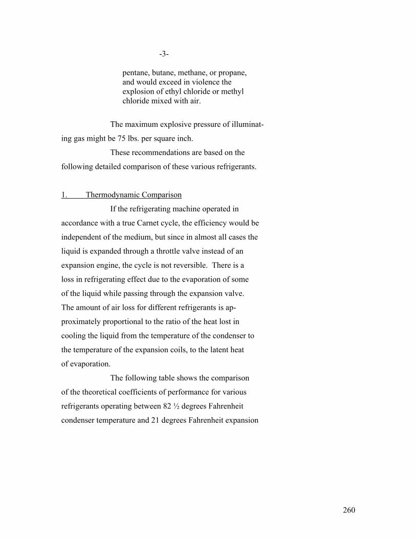
260
-3- pentane, butane, methane, or propane, and would exceed in violence the explosion of ethyl chloride or methyl chloride mixed with air.
The maximum explosive pressure of illuminat-
ing gas might be 75 lbs. per square inch.
These recommendations are based on the
following detailed comparison of these various refrigerants.
1. Thermodynamic Comparison
If the refrigerating machine operated in
accordance with a true Carnet cycle, the efficiency would be
independent of the medium, but since in almost all cases the
liquid is expanded through a throttle valve instead of an
expansion engine, the cycle is not reversible. There is a
loss in refrigerating effect due to the evaporation of some
of the liquid while passing through the expansion valve.
The amount of air loss for different refrigerants is ap-
proximately proportional to the ratio of the heat lost in
cooling the liquid from the temperature of the condenser to
the temperature of the expansion coils, to the latent heat
of evaporation.
The following table shows the comparison
of the theoretical coefficients of performance for various
refrigerants operating between 82 ½ degrees Fahrenheit
condenser temperature and 21 degrees Fahrenheit expansion
261
-4-
coil temperature. The coefficient of performance is the
ratio of the refrigerating effect divided by the required
mechanical energy expressed in B.t.u.
These coefficients of performance are
obtained from the attached temperature-entropy charts.
a- H-99386 represents the temperature-
entropy chart for ammonia with wet compression and H-99385
represents the temperature-entropy diagram for ammonia with
dry compression. The figures for these charts are made up
with the use of table in G.A. Goodenough’s “Properties
of Steam and Ammonia”.
b- H-99384 represents the temperature-
entropy diagram for wet compression of sulphur dioxide and
H-99383 represents the temperature-entropy diagram of dry
compression of sulphur dioxide. These were drawn from the
data given in the “Steam and Entropy Tables” by Cecil M.
Peabody. The data for the super-heated sulphur dioxide
vapor is calculated using the value of specific heat at
constant pressure determined by Rognault, .15438, in the
equation,
Entropy = Cp logc (T/T1)
c- H-99387 represents wet compression
for carbon dioxide and H-99388 represents dry compression
of carbon dioxide. These were plotted from the tables on

262
-5-
pages 388 and 389 of A. M. Greene, Jr’s, “Elements of Re-
frigeration”.
d- H-99389 represents wet compression and
H-99390 represents dry compression of methyl chloride. These
diagrams were plotted from the data given on pages 15 through
18 of the April, 1923, Refrigerating World, from an article,
“Properties of Methyl Chloride”, by Charles H. Herter.
e- H-99391 represents wet compression and
H-99392 represents dry compression of ethyl chloride. These
curves were plotted from data given on page 14 of the August,
1922, Refrigerating World, from an article, “Ethyl Chloride”,
by Charles H. Herter. The properties of super-heated ethyl
chloride were estimated from Regnault’s value of a specific
heat at constant pressure of .274.
f- H-99393 represents wet compression of
pentane. These were drawn from the data on pages 954 and
955 of the December 12, 1922, issue of Power, “Low Pressure
Refrigerants”, by Harry D. Edwards. The data given in
this article was not in the proper form and it was neces-
sary to estimate the specific heat of the liquid from a
value of the heat of liquid at 80 degrees Fahrenheit above
32 degrees, which was given in one of the tables. Apparently,
c = .3
The entropy of the liquid was calculated with this specific
heat, and the entropy of vaporization was calculated from

263
-6-
the values of latent heat of vaporization given in the
tables.
I could not draw the curves for dry com-
pression because I could not find a value of the specific
heat of the super-heated vapor.
g- H-99394 represents wet compression of
butane and is calculated from the same article, “Low
Pressure Refrigerants”, by Harry D. Edwards, referred to
Above. Apparently the specific heat of liquid butane is
the same as pentane, namely, C = .3
h- I could not find sufficiently complete
data on methane to make similar calculations.
Professor Keyes of Massachusetts Institute
of Technology has made some investigations on methane and
it might be possible to obtain some data from him.
i- I have not obtained sufficient data
on propane to make similar calculations. Propane is being
exploited commercially by the Carr Lighting and Power Com-
pany, Adams Building, 61 Broadway, New York City, but the
pamphlet which they publish does not give very much
scientific information.
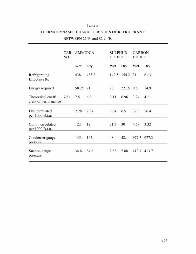
264
Table #
THERMODYNAMIC CHARACTERISTICS OF REFRIGERANTS
BETWEEN 21°F. and 82 ½ °F.
CAR- AMMONIA SULPHUR CARBON NOT DIOXIDE DIOXIDE
Wet Dry Wet Dry Wet Dry Refrigerating 438. 483.2 142.5 154.2 31. 61.3 Effect per lb. Energy required 58.25 71. 20. 22.15 9.6 14.9 Theoretical coeffi 7.81 7.5 6.8 7.11 6.96 3.24 4.11 cient of performance Lbs. circulated 2.28 2.07 7.04 6.5 32.3 16.4 per 1000 B.t.u. Cu. Ft. circulated 12.1 12. 31.3 30 4.69 3.32 per 1000 B.t.u. Condenser gauge 145. 145. 48. 48. 977.3 977.3 pressure Suction gauge 34.6 34.6 2.88 2.88 413.7 413.7 pressure

265
METHYL ETHYL PENTANE BUTANE METH PROPANE CHLORIDE CHLORIDE ANE Wet Dry Wet Dry Wet Dry Wet Dry 142.54 147.36 144. 148.4 138.5 136. ________________________________________________________________________ 21.3 21.89 19.5 20.77 19. 18.5 ________________________________________________________________________ 6.71 6.75 7.38 7.17 7.3 7.38 ________________________________________________________________________ 7.03 6.8 6.97 6.75 7.22 7.39 ________________________________________________________________________ 22.6 22.4 80. 79.2 158. 54.5 ________________________________________________________________________ 75.78 75.78 11. 11. -3.6 31.6 138. ________________________________________________________________________ 14.73 14.73 -7.7 -7.7 -12. .2 43.1

266
-8-
The above table would seem to indicate
that from the standpoint of thermodynamic efficiency, the
two best refrigerants are ethyl chloride and butane.
2. Mechanical Comparison
Under this heading, there are three questions
being considered.
a. Pressure
Due to the high pressure, I believe carbon
dioxide should not be considered. Ammonia and propane also
run at rather high pressures.
If the machine has a stuffing box, negative
pressures should be avoided, but with a sealed system I do
not consider negative pressures a disadvantage.
b. Volume
Theoretically, there should be no mechanical
preference as to whether large volumes at low pressures or
small volumes at high pressures are pumped. Practically, it
is difficult to make very small volume compressors and, there-
fore, for domestic machines I should favor the larger volume
refrigerants. However, it will be found that the most con-
venient volume depends largely on the ??? of pump.
c. Lubrication
All of these refrigerants except ammonia,

267
-9-
carbon dioxide, and sulphur dioxide have a tendency to
dissolve the oil. Therefore, if there is internal lubrica-
tion, sulphur dioxide has the advantage. If there is no
internal lubrication, either ethyl chloride or butane should
be used.
3. Chemical Properties
The following table gives some of the chemi-
cal properties.

268
-10-
TABLE #
NUMBER OF POUNDS OF REFRIGERANT WHICH RELEASED IN A ROOM
6’ x 10’ x 10’ WOULD BE EITHER POISONOUS OR EXPLOSIVE
________________________________________________________________________
Ammonia Sulphur Carbon Methyl Ethyl Pentane Butane Methane Propane Dioxide Dioxide Chloride Chloride Dangerous if in- haled for some time .125 .168 .06(*) .06(*) 3 3 3 Immediate effect on nose and throat .375 .002 Poisonous effect after burning .003 .003 Explosive or not Yes No No Yes Yes Yes Yes Yes Yes Amount to form explosive mixture 67# 84# 8#
Foot-note (*): These gases are narcotic rather than poisonous.

269
-11-
a. Poisonous
It can be seen that ethyl and methyl chloride
are very much less poisonous that either ammonia or sulphur
dioxide. In fact, they are only narcotic except after burning.
The hydrocarbon gases, pentane, butane, and
methane, are more like gasoline fumes and are not nearly as
poisonous.
b. Explosiveness
From this standpoint, sulphur dioxide is the
best, because it will not explode under any condition. Ethyl
chloride is bad because eight pounds in a small room would
form an explosive mixture. I understand that the Coldak
machine has twelve and a half pounds of ethyl chloride in it.
The hydrocarbon gases, pentane, butane, and
methane, would be more violent in their explosion than ethyl
chloride. I could get no figures as to the quantities neces-
sary to form explosive mixtures.
c. Corrosive Effect
Sulphur dioxide will form sulphurous acid
if released in a damp atmosphere, and this will have a
corrosive effect.
The figures on the poisonous qualities of
these gases and of the amounts necessary to form explosive

270
-12-
mixtures are calculated from information obtained from Professor
Ellery of Union College, and Mr. Dansizen of the Research
Laboratory.
4. Cost Comparison The purchasing agent of the Fort
Wayne Works obtained the following quotations on several of
these refrigerants:
Cost in cents per lb.
Sulphur Dioxide 9 ½ ¢
Ammonia 38 ¢
Ethyl Chloride 32 ¢
Methyl Chloride ¢
It might be thought that for true comparison these costs
should be multiplied by the number of pounds shown in the
fourth line of the table on page seven. But the total number
of pounds refrigerant in a system depends more on the design
of the evaporation coils that the thermodynamic properties.
For instance the Fort Wayne type OC-2 machine contains between
3 & 4 pounds of sulphur dioxide and the Coldak contains between
8 & 12 pounds of ethyl chloride. We can see no very good
reason why an ethyl chloride machine should contain more pounds
of refrigerant that a sulphur dioxide machine. Perhaps the
Coldak Company uses so much ethyl chloride that any leakage
there may be through the stuffing box will be a smaller per-
centage of the whole. The Fort Wayne type OC-2 is a completely
sealed machine and therefore no allowance is necessary for
leakage.
271
-13-
Apparently sulphur dioxide is the least expensive re-
frigerant for small machines.
It is likely that in large machines three times as much
SO2 would be required as ammonia and this would make the
total cost about the same.
(Editors Note: 32 PAGES OF DIAGRAMS are too faded to be included)

272
-13-
“A refrigerator is of little value
which will not operate with reasonable care and ice consumption at 45 degrees Fahrenheit during the summer months.”
The following is copied from the last page
of the bulletin gotten out by the Frigidor Corporation:
MILK TEST
In an average room.
In an average refrigerator.
At a very low temperature such as in not
possible to obtain under the usual conditions in an ice-cooled
system, but is a regularly present in the Frigidor system.
NUMBER OF BACTERIA PER CUBIC CENTIMETER# IN
CERTIFIED MILK HELD AT DIFFERENT TEMPERATURES
Approximate Number of Living Bacteria at Following Temperatures
Days Room Average Days Frigidor Held Temperature Refrigerator Held Temperature 68° F 54° F 33° F Fresh 3,000 sweet 3,000 sweet Fresh 2,900 sweet 1 1,500,000 “ 8,000 “ 1-8 days 2800 to 3,100 “ 2 31,000,000 “ 150,000 “ 9 “ 22,000 “ 3 300,000,000 sour 2,300,000 “ 10 “ 200,000 “ 4 ********** “ 125,000,000 “ / 11 “ 1?,000,000 “ 5 ********** “ 500,000,000 sour (#): About a quarter of a teaspoonful. (/): End of experiment with milk still sweet. It will be seen that the numbers of bacteria
in the milk after two (2) days of the average refrigerator

273
-14-
temperature were larger than they were at the refrigerator
temperature after nine (9) days. Poorer grades of milk
would show far less satisfactory results for the ice cool-
ing system.
I wrote the State Board of Health for their
opinion on the proper temperature and humidity for domestic
ice machines. They had no such data and forwarded my letter
to the Department of Farms and Markets. The Department of
Farms and Markets had no data on this subject, and at their
suggestion I wrote the Department of Penology at Cornell
University. The Department of Penology replied giving a
number of figures which applied to cold storage warehouse
where food is kept for months or years. They forwarded my
letter to the Department of Dairy Industry, Cornell
University, seemed to fool that milk and butter could be
kept satisfactorily for a few weeks with temperatures of
from forty to fifty degrees Fahrenheit.

274
-15-
f. In traveling around the country, I
find that most of the people who have investigated domestic
refrigeration feel that the temperature in the food com-
partment should be below 45° F. and, as a factor of safety,
try to obtain a temperature of 40°.
The temperatures obtained in this average
box are over 45° on a 70 degree day, and as high as 58° on
a 90 degree day.
g. How can an average temperature of 40°
be obtained in the food compartment of this box by melting
ice?
On pages 14 and 15 of “Elements of Refri-
geration”, by Professor A. M. Greene, Jr., curves are given
showing the temperatures which can be obtained by mixing
salt and water. Apparently, a temperature of minus 10° F.
can be obtained by mixing one-quarter of a pound of salt
with three-quarters of a pound of ice. It is my under-
standing that Professor Greene’s tables are copied from
Bulletin No. 98 of the United States Department of Agri-
culture.
Assume that the temperature of the ice in
the refrigerator can be lowered by the above method. Line
four of the table shows the ice temperature which would
have to be obtained to hold the box at 40° on a 70 degree
day. The calculations are as follows.

275
-16-
The temperature difference between the bood
and the outside air would be thirty degrees. Assuming tha
the best heat transmission is directly proportional, 1.28 lbs.
of ice would be melted.
In a similar manner, it can be calculated
that the ice must be minus 9° F. in order to maintain the
food compartment at 40°, with a room temperature of 90°.
g. Curves H-99367 illustrate graphically
the data in lines 1,2,3,4, and 5 of the table. It
seems evident that the air passages in the ice box are to
restricted. This box could probably be greatly improved
by enlarging them. It would be difficult to state

276
-17-
theoretically just how much could be accomplished in this
way.
i. One very obvious way of improving the
box would be to increase the insulation.
If the ice is 32° F. and the food com-
partment is 40° F., the heat transfer between them by
equation (3) is 0.8 lbs.
In order that a meltage of 0.8 lbs. May
maintain a difference of 30 degrees between the food com-
partment and the outside air, the insulation must be in-
creased so that only .0905 B.t.u. will flow per square foot,
per hour, per degree. The reciprocals of the conductivity
can be treated as resistance. The additional resistance
required is the difference between the total required re-
sistance and the present resistance.
(1/.0905) – (1/.143) = (1/25)
Therefore, the additional insulation must
have a conductivity of less that .25 B.t.u. per square
foot, per hour, per degree.
Non-Pareil corkboard, 1” thick has a con-
ductivity of .25 B.t.u. per hour, per square food, per
degree.
Therefore, the additional insulation should
consist of 1” Non-Pareil corkboard. The price of this is
277
-18-
about 7 ¾ cents per board-foot. Therefore, 42 ½ board-
feet would cost $3.30. Double this to cover the labor of
installing it, and multiply by three to cover commercial
percentages. This shows that this extra inch of cork insu-
lation could have been furnished with box at an additional
selling price of about $20.00.
Assuming 6 percent interest on the invest-
ment and 10 percent depreciation, it is found that the
annual cost is $3.00.
On the other hand, better refrigeration
is assured and 0.26 lbs. Of ice per hour is saved. This
is 6.25 lbs. per day. Assuming that the box is used during
six months of the year, the annual saving is 1140 lbs., or
11 ½ hundred-weight. At 60 cents per hundred-weight, this
corresponds to a saving of $6.85 worth of ice, or a net
saving of $3.65. This is 18 percent on the investment as
well as better refrigeration. On a 90 degree day, this
box would melt 1.12 lbs. of ice and the food compartment
would rise to 48°.
If it is desired to keep the box at 40°
with a room temperature of 90 degrees, the conductivity
of the insulation must be resized to .054.
(1/.054) – (1/.143) = (1/.087)

278
-19-
Therefore, the additional insulation must
have a conductivity of less than .087 B.t.u. per square
feet, per hour, per degree. This would require about 3”
of Non-Pareil corkboard.
The interest and depreciation on this would
be $10.95.
This box under average 70 degree conditions
would only melt .55 lbs. of ice per hour and the temperature
of the food compartment would be about 34 ½ degrees.
There would be a saving of .51 lbs. per hour, or 2240 lbs.
during the six warmer months. At 60 cents per hundred-weight,
this would be $13.50 gross saving. The not saving would be
$2.55, which is 4 ¼ percent profit on the $60.00 additional
investment.
j. The curves on H-99368 show graphically
the effect which additional insulation has on the food com-
partment temperatures and the rates of ice meltage.
k. Dr. John R. Williams in his paper before
the Third International Congress on Refrigeration, in 1913,
takes up the question of the economy which can be obtained
by adding extra cork insulation in the refrigerator. The
following conclusions are quoted from this paper:
“Neither the cellar nor pantry in the home are efficiently cold to keep perishable foods from spoiling during the warm months of the year; therefore, every home should have a good
refrigerator.

279
-20- “Only about half the homes in the city have refrigerators; the other half are com- pelled to depend upon the inadequate protection afforded by the cellar. “The majority of domestic refrigerators are inefficient because they consume too much ice and do not maintain a temperature low enough to prevent food from spoiling. “The chief explanation of their inefficiency is to be found in the lack of suffi- cient and proper installation. “There are a large number of shoddy refrigerators on the market which contain no other insulation than a sheet or two of paper. They are sold chiefly to working people who can ill afford to use them, because they are both unsanitary and grossly uneconomical in the consumption of ice. “The waste from ice meltage because of improper insulation of refrigerators in Rochester house (population of city, 880,000) amounts to 60,000 tons yearly, or about $380,000. “At least $100,000. more is wasted yearly in the present competitive system of delivery. # “Unnecessary waste is now making refrigeration cost consumers from three to five times as much as it should. “There are certain simple directions which will be of assistance in selecting a refrigerator. If they are observed, the purchaser can at least Avoid being defrauded. “One should insist upon seeing a section of the wall of the refrigerator which he contem- plates buying. Honest manufacturers are always will to let customers know the character of their wares. “Do not buy a box which does not bear the name and address of the maker, nor one Foot-note: See last page of appendix #4 for cost of delivery.

280
-21- sold only under the name of a retail dealer. If the manufacturer is ashamed to acknowledge his handiwork, you are justified in suspecting fraud. “Do not buy a box which contains less than three inches of good insulation, not including the wooden case or the metal or tile lining. “Beware of impossible “vacuum”, doubtful “dead air space”, and no-good paper insulation. “Money invested in insulation will be returned many times in the saving in ice bills. Added insulation mean not only economy in ice Consumption, but also lower temperatures in the Refrigerator and the less spoiling of food.”
Mr. F. Nichols of Pittsburgh, Pa., presented
a paper at the joint meeting of the A.S.R.E. and the A.S. M.E.,
December 4, 1922, entitled, “The Economic Thickness of In-
sulation in the Refrigerating Field”. Mr. Nichols has made
up a general formula for the most economic thickness of in-
sulation, based on interest and depreciation on investment,
and operating costs.
3. Value of Baffles
It is an interesting question as to why
ice boxes are made with air circulation to a separate ice
compartment, instead of putting the ice in the food com-
partment. Experiments with our Fort Wayne type OC-2 machine
in a Jewett box show that better temperatures can be obtained,
when the baffles are removed, by direct radiation and con-

281
-22-
duction from the brine tank to the food. Why do not ice box
builders do the same thing? One possible advantage of the
air circulation method may be evident from the following
hypothetical operation of the ice box.
a. Warm air enters the food compartment
when the door is opened.
b. The warm air is convected to the ice
compartment where it is chilled, and any excess moisture
condensed out.
c. The air passing from the ice compartment
to the food compartment warms up slightly, which decreases
the humidity.
Thus, it is seen that even with an ice box
there is a theoretical possibility of obtaining dry refri-
geration by means of air circulation.
On the other hand, if the ice were in the
same compartment with the food, any moisture condensing the
air might fall in the form of a mist or dew on the food,
making it soggy.

282
General Electric Company Internal Correspondence
Subject: REPORT ON DOMESTIC REFRIGERATING MACHINES. Location: Referring to: Schenectady, Sept. 20, 1923. Publication Department, Building #2. Will you please insert the following note in
your copy of the report on “Domestic Refrigerating Machines”.
appendix #12, “Balsa Boxes”.
I have just learned confidentially that there
has been trouble with some of the cement lined ice boxes made
by the American Balsa Company, due to the Balsa wood warping
and cracking the cement. It is therefore necessary for us to
withdraw our approval of this box. If the General Electric
Company decides to go into domestic refrigerating machine
business, it will probably be necessary to make a little
further study of the refrigerator box problem.
At note of this should be made in paragraph #3,
on page 10, Report #1, “Summary and Conclusions”.
A. R. STEVENSON, JR.
CONSULTING ENGR. DEPT.
ARS;DW
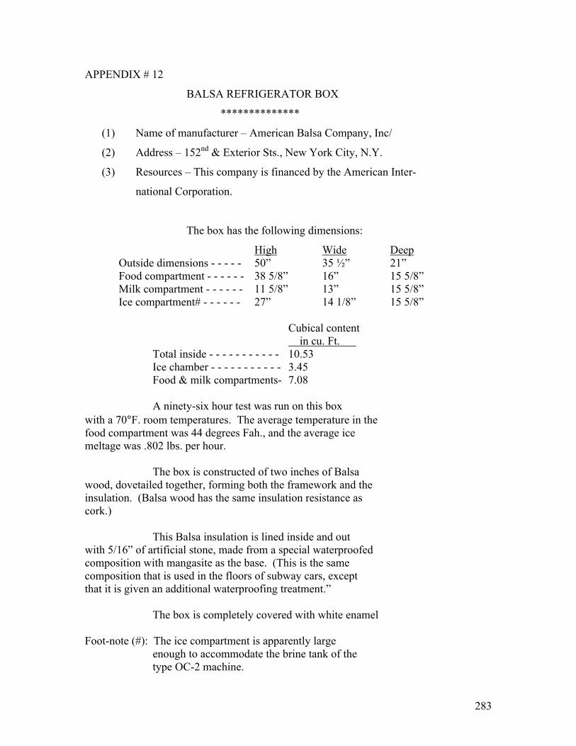
283
APPENDIX # 12
BALSA REFRIGERATOR BOX
**************
(1) Name of manufacturer – American Balsa Company, Inc/
(2) Address – 152nd & Exterior Sts., New York City, N.Y.
(3) Resources – This company is financed by the American Inter-
national Corporation.
The box has the following dimensions:
High Wide Deep Outside dimensions - - - - - 50” 35 ½” 21” Food compartment - - - - - - 38 5/8” 16” 15 5/8” Milk compartment - - - - - - 11 5/8” 13” 15 5/8” Ice compartment# - - - - - - 27” 14 1/8” 15 5/8” Cubical content in cu. Ft. Total inside - - - - - - - - - - - 10.53 Ice chamber - - - - - - - - - - - 3.45 Food & milk compartments- 7.08 A ninety-six hour test was run on this box with a 70°F. room temperatures. The average temperature in the food compartment was 44 degrees Fah., and the average ice meltage was .802 lbs. per hour. The box is constructed of two inches of Balsa wood, dovetailed together, forming both the framework and the insulation. (Balsa wood has the same insulation resistance as cork.) This Balsa insulation is lined inside and out with 5/16” of artificial stone, made from a special waterproofed composition with mangasite as the base. (This is the same composition that is used in the floors of subway cars, except that it is given an additional waterproofing treatment.” The box is completely covered with white enamel Foot-note (#): The ice compartment is apparently large enough to accommodate the brine tank of the type OC-2 machine.

284
Balsa - #2 paint both inside and out. The box sells at retail for $104.00. I under- stand from one of their employees that the factory cost is $80.00. I believe that we might buy these boxes for $90.00 in lots of one hundred, arranged for the reception of the type OC-2 machine. The rating of a machine suitable for use with this Balsa Box could be estimated as follows: The total outside area of the box is 49.6 sq. ft. There are two inches of Balsa wood insulation and 5/8” of artificial stone. According to a paper by H. C. Dickinson and M. S. Van Dusen, of the National Bureau of Standards, reprinted in the American Society of Refrigerating Engineers Journal, September 1916, the Balsa wood has a coefficient of heat transmission 12-1/2 per cent greater than cork. In the same paper the average coefficient of heat transmission for brick or cement is about sixteen times as great as that of cork. We have assumed that this figure can be used for the mangasite artificial stone. The insulation is therefore equivalent to 2” Balsa wood equivalent to 1.78” cork 5/8” mangasite “ “ .04” “ Total insulation 1.82”
x Total air film (inside and out) Equivalent to .5” “ 2.32” ∅ B.t.u. per hour per sq. ft. per degree is .1325
x(Foot Note) See pages 8 and 9 of appendix #6 where it was calculated that a flow of 152 B.t.u. per hour through a surface of 42.5 sq. ft. made an air film drop of 2.9°F. (Average of 3.2° and 2.6° calculated by different methods). The total drop inside and out would be double this, or 5.8°F. Since 3.58 B.t.u. per hour per sq. ft. cause a drop of 5.6° the two air films have a coefficient of heat transmission of .618 which is equivalent to ½” of cork. ∅ (Foot Note) The coefficient of heat transmission of cork is .308 B.t.u. per hour per sq. ft. per degree per inch of thickness, according to the same paper by Mesars. Dickinson and Van Dusen.

285
Balsa - #3.
For a 26° drop B.t.u. per sq. ft. per hour equals 3.45 For an area of 49.6 sq. ft. equals 171 B.t.u. This is equivalent in pounds of ice per hour to 1.19. The American Balsa Company claim to have made a test
which indicated an ice meltage of .802 pounds of ice per hour. This is 32.5 percent better that the above estimated figure. In order to justify this test it would be necessary to assume that either the Balsa wood or the magnesite has a much lower coefficient of heat transfer than we estimated. In making a conservation decision as to the proper rating for a machine to refrigerate this box we have used our own theoretical figures rather than the test made by the American Balsa Company. AVERAGE LOAD. (See page 4 Report #7) Pounds ice per 24 hours To hold box at 40° with room at 70° 33 To freeze 12-1/2# ice once in 24 hours 15.7 To cool food once in 24 hours 2.35 Opening box 25 times .82 51.87 The Fort Wayne type OC-2, form G, air cooled machine could easily carry this load with a brine temperature of about 23°F. MAXIMUM LOAD (See page 3 Report #7) Rate pounds ice per hour To hold box at 44° with room at 90° 2.11 To freeze 12-1/2# ice in 24 hours .69 To cool food in three hours 1.06 Opening box four times per hour .47 4.33
Which is a rate of refrigeration equal to 104 pounds of ice per day.
In redesigning the OC machine for air cooled operation with this box, a capacity of at least 106 pounds of ice per 24 hours with 26° brine and 90° room temperature should be maintained.

286
APPENDIX #12-A INFORMATION FURNISHED BY MR. STUART OTTO ON BALSA BOX _______________
Mr. Stuart Otto told me that he has several
of the Balsa boxes in his factory and that the Balsa wood had
the following defects:
1- The Balsa wood did not have the qualities
claimed for it.
2- The magnesite covering cracked off.
3- The white enamel paint would not stick
properly to the magnesite.
ARStevenson, Jr-DW
February 19, 1924
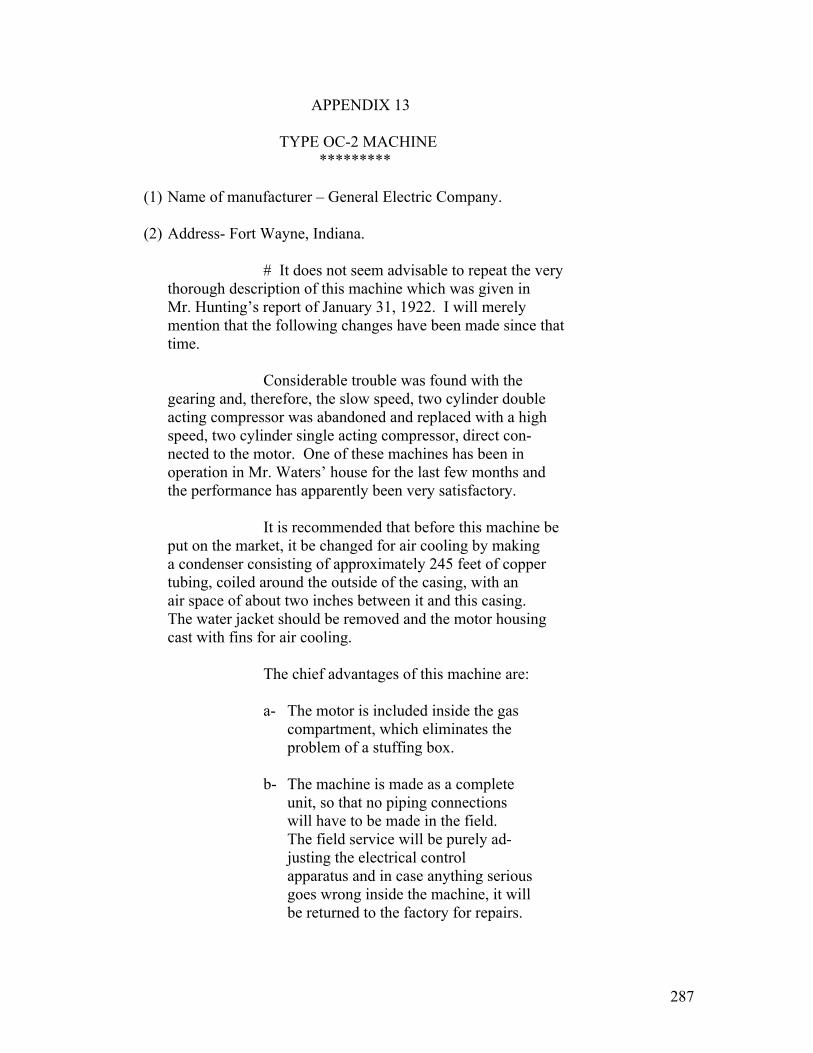
287
APPENDIX 13
TYPE OC-2 MACHINE *********
(1) Name of manufacturer – General Electric Company. (2) Address- Fort Wayne, Indiana.
# It does not seem advisable to repeat the very thorough description of this machine which was given in
Mr. Hunting’s report of January 31, 1922. I will merely mention that the following changes have been made since that time.
Considerable trouble was found with the gearing and, therefore, the slow speed, two cylinder double acting compressor was abandoned and replaced with a high speed, two cylinder single acting compressor, direct con- nected to the motor. One of these machines has been in operation in Mr. Waters’ house for the last few months and the performance has apparently been very satisfactory. It is recommended that before this machine be put on the market, it be changed for air cooling by making a condenser consisting of approximately 245 feet of copper tubing, coiled around the outside of the casing, with an air space of about two inches between it and this casing. The water jacket should be removed and the motor housing cast with fins for air cooling. The chief advantages of this machine are:
a- The motor is included inside the gas compartment, which eliminates the problem of a stuffing box.
b- The machine is made as a complete
unit, so that no piping connections will have to be made in the field. The field service will be purely ad- justing the electrical control apparatus and in case anything serious goes wrong inside the machine, it will be returned to the factory for repairs.

288
The machine could probably be put on the market at a price of $593.00. (See Part III of Report #2. Manufacturing and Financial.) The machine as present takes about .315 watt-hours per B.t.u. Then redesigned for Foot-note (#): An abstract from Mr. Hunting’s report is included in appendix #69.
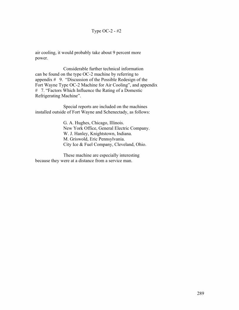
289
Type OC-2 - #2 air cooling, it would probably take about 9 percent more power. Considerable further technical information can be found on the type OC-2 machine by referring to appendix # 9. “Discussion of the Possible Redesign of the Fort Wayne Type OC-2 Machine for Air Cooling”, and appendix # 7. “Factors Which Influence the Rating of a Domestic Refrigerating Machine”. Special reports are included on the machines installed outside of Fort Wayne and Schenectady, as follows: G. A. Hughes, Chicago, Illinois. New York Office, General Electric Company. W. J. Hanley, Knightstown, Indiana. M. Griswold, Eric Pennsylvania. City Ice & Fuel Company, Cleveland, Ohio. These machine are especially interesting because they were at a distance from a service man.
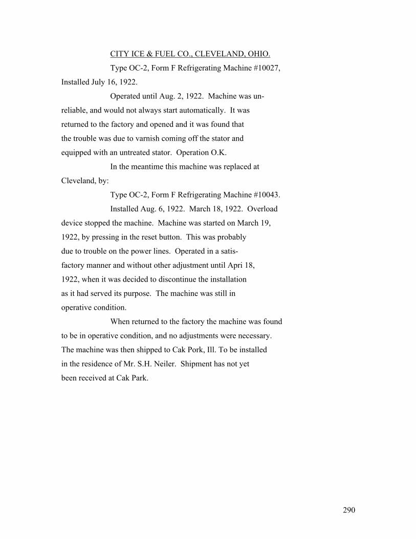
290
CITY ICE & FUEL CO., CLEVELAND, OHIO.
Type OC-2, Form F Refrigerating Machine #10027,
Installed July 16, 1922.
Operated until Aug. 2, 1922. Machine was un-
reliable, and would not always start automatically. It was
returned to the factory and opened and it was found that
the trouble was due to varnish coming off the stator and
equipped with an untreated stator. Operation O.K.
In the meantime this machine was replaced at
Cleveland, by:
Type OC-2, Form F Refrigerating Machine #10043.
Installed Aug. 6, 1922. March 18, 1922. Overload
device stopped the machine. Machine was started on March 19,
1922, by pressing in the reset button. This was probably
due to trouble on the power lines. Operated in a satis-
factory manner and without other adjustment until Apri 18,
1922, when it was decided to discontinue the installation
as it had served its purpose. The machine was still in
operative condition.
When returned to the factory the machine was found
to be in operative condition, and no adjustments were necessary.
The machine was then shipped to Cak Pork, Ill. To be installed
in the residence of Mr. S.H. Neiler. Shipment has not yet
been received at Cak Park.

291
C. A. HUGHES, -EDISON ELECTRIC APP. CO., CHICAGO, ILL.
Type OC-2, Form E Refrigerating Machine #10023.
Installed in the showrooms of the Edison Electric
Appliance Co., Chicago, Ill., on Nov. 29, 1920.
Machine stalled on Dec. 3, 1920, due to the fact
that it was not equipped with an equalizing valve. Machine
was replaced by another machine which was equipped with an
equalizing valve, although it was one of the first models of
an equalizing valve used in these machines. This improved
conditions, but did not entirely correct the trouble. The
replacing machine was:
Type OC-2, Form E Refrigerating Machine #10030.
Installed Dec. 4, 1920.
Machine was transferred to Mr. Hughes’ residence
about March 16, 1921.
Machine failed on March 22, 1921, due to trouble
with an old style equalizing valve. It was replaced by:
Type OC-2, Form E Refrigerating Machine #10029.
installed March 30, 1921.
Thermostat became grounded and was replaced by a
new style thermostat on June 21, 1921. Service man necessary.
On April 13, 1922 service man was again called to
Chicago to adjust control device.
Although this machine was functioning properly,
it was replaced on Nov. 14, 1922 by a Form F machine with a vitreous

292
-2-
enameled brine tank, because it was our policy at that
time to bring up-to-date all machines which were then in
service.
Type OC-2, Form F Refrigerating Machine #10026.
Installed Nov. 14, 1922. In operation to date.
No adjustments.
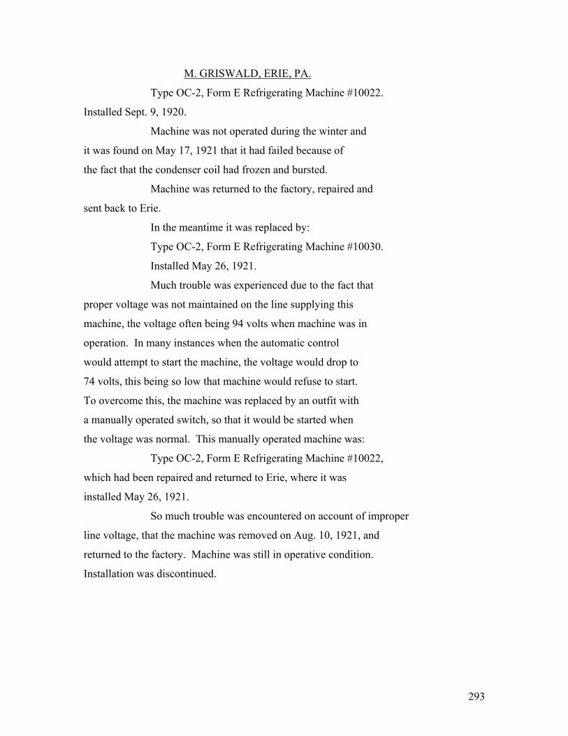
293
M. GRISWALD, ERIE, PA.
Type OC-2, Form E Refrigerating Machine #10022.
Installed Sept. 9, 1920.
Machine was not operated during the winter and
it was found on May 17, 1921 that it had failed because of
the fact that the condenser coil had frozen and bursted.
Machine was returned to the factory, repaired and
sent back to Erie.
In the meantime it was replaced by:
Type OC-2, Form E Refrigerating Machine #10030.
Installed May 26, 1921.
Much trouble was experienced due to the fact that
proper voltage was not maintained on the line supplying this
machine, the voltage often being 94 volts when machine was in
operation. In many instances when the automatic control
would attempt to start the machine, the voltage would drop to
74 volts, this being so low that machine would refuse to start.
To overcome this, the machine was replaced by an outfit with
a manually operated switch, so that it would be started when
the voltage was normal. This manually operated machine was:
Type OC-2, Form E Refrigerating Machine #10022,
which had been repaired and returned to Erie, where it was
installed May 26, 1921.
So much trouble was encountered on account of improper
line voltage, that the machine was removed on Aug. 10, 1921, and
returned to the factory. Machine was still in operative condition.
Installation was discontinued.

294
W.J. HARLEY - - KNIGHTSTOWN, IND.
Type OC-2, Form E Refrigerating Machine #10023
was installed on Sept. 1, 1920. Ran till Oct. 18, 1920.
Oct. 7, 1920, thermostat and water valve were not
working properly. Wrote Mr. Hanley and asked him to make
adjustments as per his suggestion in his letter of Oct. 6, 1920.
Before these adjustments were made, trouble was
experienced because the machine would not start up with brine
tank at cold temperatures.
On Oct. 18, 1920, the machine was removed and re-
turned to the factory, inspected and it was found that this
failure was due to the motor not being able to start the
machine until the pressures were equalized. (This was one of
the early models and was not equipped with an equalizing valve.)
The machine was repaired and equipped with an equalizing valve
which prevented a recurrence of this trouble.
In the meantime this machine was replaced at
Mr. Hanley’s residence by:
Type OC-2, Form E Refrigerating Machine #10026,
installed Oct. 18, 1920. Ran until June 18, 1921. No
adjustments during this time.
Machine failed on June 18, 1921, due to a grounded
metal glass lead. This was one of the old style metal glass
leads, and was ??? was of the later loads ??? with
greater space between the conductor and the sheath at the end

295
-2-
inside the machine.
Machine was returned to the factory, repaired,
and sent back to Knightstown, where it was again installed
on July 1, 1921.
No adjustments until June 8, 1922, when the machine
failed, due to gas leak through porous casting near the
charging plug.
Machine was returned to the factory, and was
replaced by:
Type OC-2, Form F Refrigerating Machine #10037
which was installed on June 14, 1922.
This machine operated in a satisfactory manner and
without adjustment, but on Dec. 18, 1922, it was replaced by
an up-to-date machine because it was our policy at that time
to replace all machines which were equipped with the old style
painted brine tanks. When the machine was returned to the
factory it was in operative condition, but the brine tank was
badly corroded.
It was replaced by:
Type OC-2, Form F Refrigerating Machine #10032,
which was installed on Dec. 18, 1922, and which is still
operating. No adjustments to date.
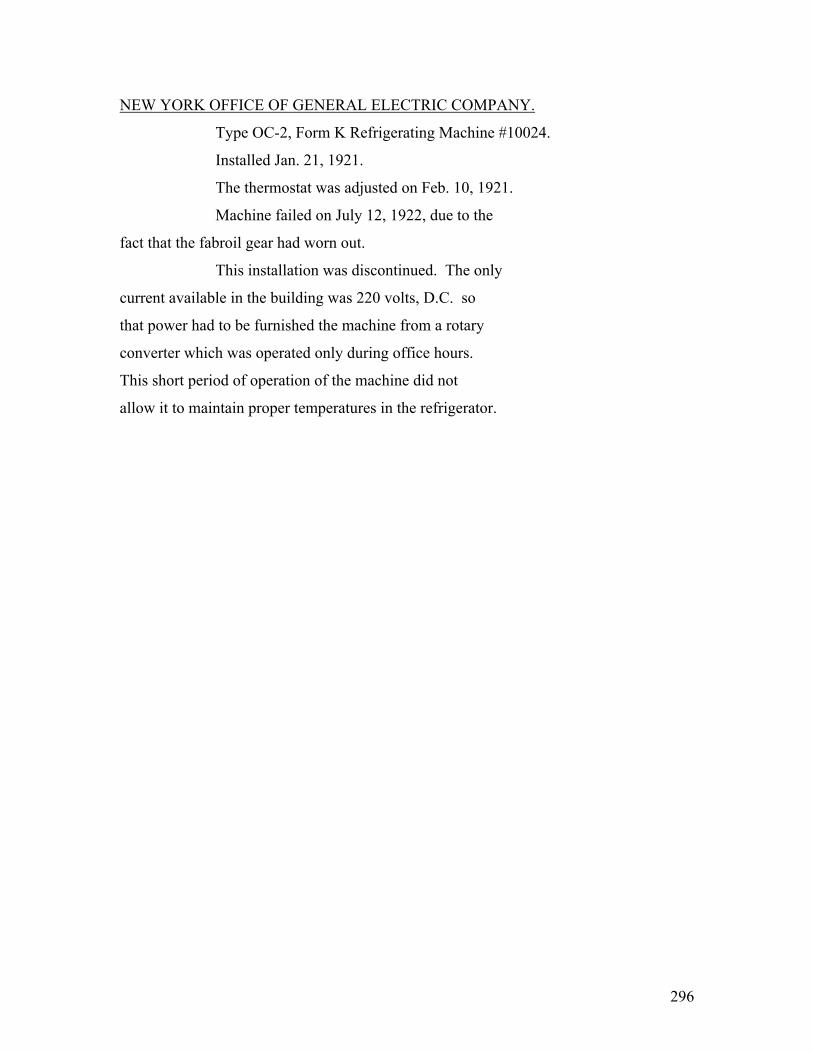
296
NEW YORK OFFICE OF GENERAL ELECTRIC COMPANY.
Type OC-2, Form K Refrigerating Machine #10024.
Installed Jan. 21, 1921.
The thermostat was adjusted on Feb. 10, 1921.
Machine failed on July 12, 1922, due to the
fact that the fabroil gear had worn out.
This installation was discontinued. The only
current available in the building was 220 volts, D.C. so
that power had to be furnished the machine from a rotary
converter which was operated only during office hours.
This short period of operation of the machine did not
allow it to maintain proper temperatures in the refrigerator.

297
APPENDIX #13-A CORBLIN COMPRESSOR _____________ Principle:
The membrane compressor is an apparatus in
which a thin metallic disc pinched between two circular plates
is allowed to oscillate up and down into elliptical spaces
hollowed out in the thickness of the plates.
It is there oscillations of the disc which,
by means of poppet valves placed in one of the plates, produces
the suction and compression of the gas, which is sheltered by
the membrane from the lubricant and other impurities.
A piston moving in a cylinder full of oil
pushes the membrane up and down by oil pressure.
An extra small compensating pump replaces any
oil which escapes between the piston and the cylinder, and thus,
by maintaining a full supply of oil, insures that the membrane
is always pushed down to its lower position, doing away with
all clearance volume.
The membrane compressor does away with all
oiling and stuffing boxes and preserves the gas in a pure con-
dition, at the same time economizing the power. (See Communi-
cation (text illegible)
LeBlanc, January 3, 1921.) The fact that there is no internal
oiling permits the use of gases which might attack the lubri-
cant, and renders unnecessary oil separators which ordinarily

298
-2-
complicate other refrigerating machines. It also prevents
any gumming of the valves and valve ports, which is one of
the principal causes of failure of small machines. It also
prevents the stirring of the lubricant and the refrigerant,
which very often produces a soapsuds which interferes with
the valves and sometimes make it necessary to dismantle the
machine.
Elimination of the stuffing box eliminates
the losses and permits the use of noxious gases. It is no
longer necessary to watch the heating of the stuffing box, or
to keep the piston lined up with the stuffing box. The ab-
sence of the stuffing box reduces the friction of the piston
which moves in oil and gives a very high mechanical efficiency.
Elimination of clearance volumes makes a very high volumetric
efficiency.
The plunger of the oil pump has a relief
valve in it so that when the pressure reaches a certain point
the oil is allowed to go up through the plunger. This pre-
vents breaking the machine by excessive oil pressures.
It is claimed that this membrane compressor
has 50% better efficiency that some other types of small ma-
chines.
It can be taken apart completely by anyone
in about two hours. The membrane (text illegible)
three screws. The valves can be removed by loosening two other
screws.
The crank shaft bearings and the connecting
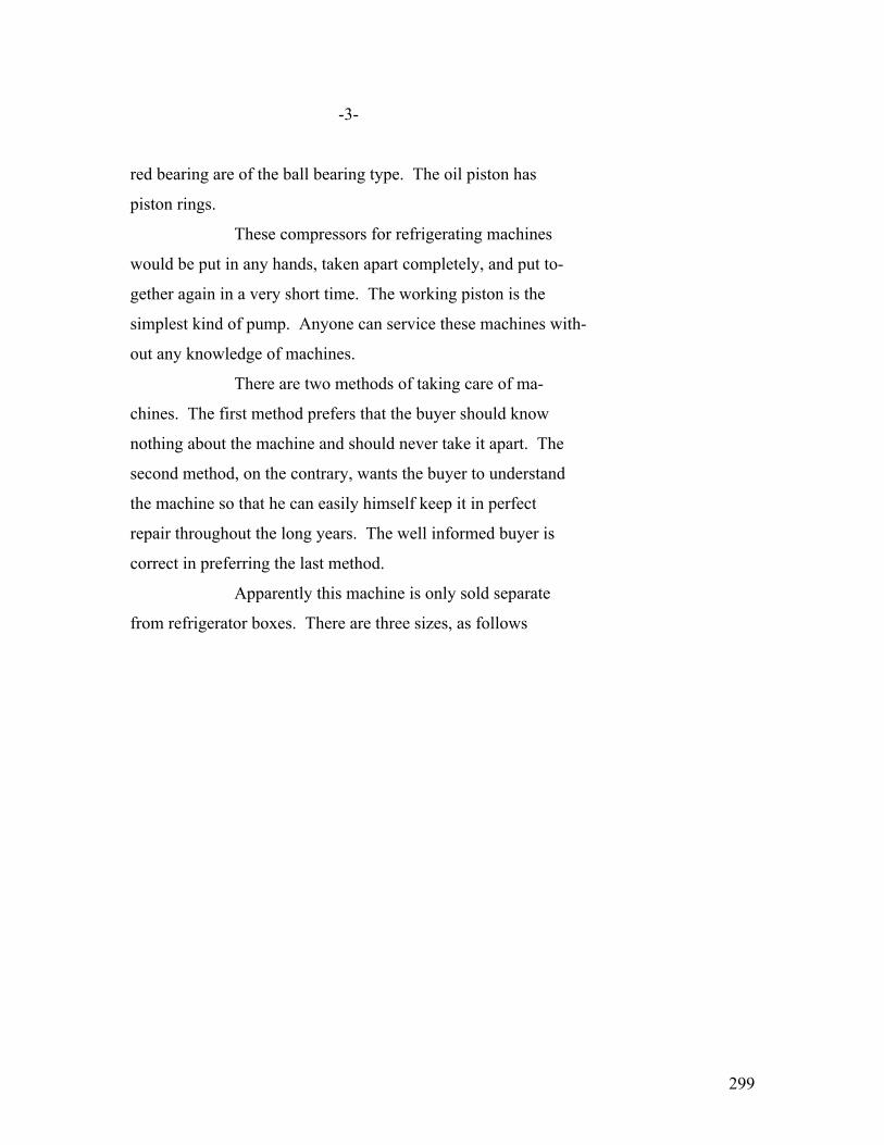
299
-3-
red bearing are of the ball bearing type. The oil piston has
piston rings.
These compressors for refrigerating machines
would be put in any hands, taken apart completely, and put to-
gether again in a very short time. The working piston is the
simplest kind of pump. Anyone can service these machines with-
out any knowledge of machines.
There are two methods of taking care of ma-
chines. The first method prefers that the buyer should know
nothing about the machine and should never take it apart. The
second method, on the contrary, wants the buyer to understand
the machine so that he can easily himself keep it in perfect
repair throughout the long years. The well informed buyer is
correct in preferring the last method.
Apparently this machine is only sold separate
from refrigerator boxes. There are three sizes, as follows
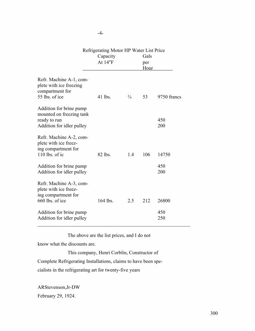
300
-4-
Refrigerating Motor HP Water List Price Capacity Gals At 14°F per Hour Refr. Machine A-1, com- plete with ice freezing compartment for 55 lbs. of ice 41 lbs. ¾ 53 9750 francs Addition for brine pump mounted on freezing tank ready to run 450 Addition for idler pulley 200 Refr. Machine A-2, com- plete with ice freez- ing compartment for 110 lbs. of ic 82 lbs. 1.4 106 14750 Addition for brine pump 450 Addition for idler pulley 200 Refr. Machine A-3, com- plete with ice freez- ing compartment for 660 lbs. of ice 164 lbs. 2.5 212 26800 Addition for brine pump 450 Addition for idler pulley 250 _____________________________________________________________ The above are the list prices, and I do not
know what the discounts are.
This company, Henri Corblin, Constructor of
Complete Refrigerating Installations, claims to have been spe-
cialists in the refrigerating art for twenty-five years
ARStevenson,Jr-DW
February 29, 1924.

301
APPENDIX #14 SAVAGE ARMS COMPANY ************ (1) Manufactured by: Savage Arms Company. (2) Address: Utica, New York. (3) Resources: This company has a manufacturing capacity of $5,000,000, approximately, total for all plants. Their domestic refrigerating machines will not be available until August or September, 1923. (4) Patents: 1,373,174 Jay Grant DeRemer May 29, 1921 1,373,175 “ “ 15,590 “ “ 15,591 “ “ (5) Remarks:
The principle of the Savage Arms machine can best be described as follows. a – Consider a tank full of mercury, with a screw dipping into it. The screw should be surrounded by a tube, so that the threads form a spiral passage. [ diagram ] The screw and the casing are rotated about their own axis. The threads pick up some mercury and trap some air ??? revolution. The mercury is too heavy to be carried around with the screw and, therefore, remains in the bottom. As the screw is rotated, the mercury is carried along the bottom, while the un trapped air is carried along the top. If the upper and of the spiral passage is connected to an air receiver under pressure, the mercury is (Text Illegible) of these differences in height of mercury will be equal to the pressure against which the air is pumped. Such a contrivance could be used as a pump to (Text Illegible) The refrigerant, but about 250 turns would be (Text Illegible)
302
-2 -
in order to build up the required pressure. This would be quite bulky and require a great deal of mercury. The Savage Arms Company have improved on this principle by using centrifugal force instead of gravity. In practice, the value of centrifugal force, which they use, is twenty-five times the force of gravity: therefore, only about ten turns are required. The patents mentioned about have been granted to the Savage Arms Company covering this arrangement. These patents give a very complete description of the contrivance. Briefly, it consists of a horizontal disc about 15” in diameter, which revolves about a vertical axis. At the periphery of this disc, there is a bearing inclined about fifteen degrees from the vertical. Mounted in this bearing is a tube about 4” in diameter by 15” high, shown in the drawing H-108901 The tube with the spiral passageway, although the bottom of it is carried in a circular path, does not rotate with respect to the earth. When the tube is on the right side, the centrifugal force is to the right, when the tube is on the left side, the centrifugal force is to the left. Thus, the centrifugal force revolves about the tube, pulling the mercury around with it. In drawing H-108901, the auction chamber is re- presented by “A”. The shaded portion shows the level of the mercury, which is held out by the centrifugal force. (The level of mercury is perpendicular to the centrifugal force.) When the table has rotated, bringing the machine to the left, the mercury will stand in the other side of this compartment. As the mercury swings around the compartment, it is caught by the spiral threads and, at the same time, a certain amount of air is trapped. It will be noticed that the outside spiral slots

303
are shaded, showing that they are full of mercury; whereas, the inside spiral slots are filled with gas. As the cen-
trifugal force changes from side to side (Text Illegible) the gas around through the spiral passage until both the mercury and the gas are delivered in the compression chamber, “B”.
[ diagram (Illegible) ]
- 3 - It will be noticed that in the compression chamber, “B”, the mercury again stays in the outside with its surface
perpendicular to the centrifugal force. The gas cannot get down through the surface of the mercury and, therefore, goes up the annular passage to the discharge tube, while the mercury flows up through the central passage, back into the suction chamber. The suction and discharge tubes are wound up in spirals of the same shape as the hair-spring in a watch. About fifteen feet of pipe is used. As the machine rotates, these pipes are twisted about fifteen degrees. This is one degree per foot. The Savage Arms Company have checked up the strain in the material with the tests which have been made at the University of Illinois. This twist of one degree per foot, puts a strain on the material less than the yield point. Therefore, the material should last indefinitely. The Savage Arms Company have had some of these machines run- ning about a year, without any sign of breakage. This pump has the following advantages: a - No internal lubrication. Therefore, any refrigerant can be used, and an oil seperator is not required. b - There is no stuffing box. c - It is impossible to explode the machine because after a certain pressure is reached the mercury will run backward through the spirals.

304
The machines which the Savage Arms Company have are still laboratory models, and look very expensive, but Mr. Goll, Mr. Dalton, Mr. Blake, and myself all feel that it should be possible to redesign this machine mechanically so that it could be built for a low factory cost. So much money has been spent in trying to solve the domestic refrigeration problem along stereotyped lines, that it is reasonable to believe that real success can only be achieved by some unusual development. Mr. Perkins, the engineer of the Audiffren Company, told me that he did not
(Text Illegible) be solved until somebody invented a machine which would be just as unusual today as the Audiffren was a dozen years ago. I believe the Savage Arms machine fills Mr. Perkins’ speci- fication.

305
- 4 - The Savage Arms machine can also be built in larger sizes in a construction similar to the Audiffren con- struction. In this case, the spiral tubing is omitted and the compressor, condenser, and expansion coils are all included in one rigid body which is rotated about an axis.
[ diagram (Illegible)]
The compressor and condenser end of this would be
sprayed with water and the expansion end would be sprayed with
brine. I believe that this Savage Arms machine is so much
simpler that if properly pushed, it will supersede the
Audiffren machine in the larger sizes.

306
TESTS OF THE SAVAGE ARMS MACHINE.
Schenectady, Feb. 28, 1924.
Mr. Robert Steck.
Fort Wayne Works.
Dear Mr. Steck:
I want to congratulate someone on the beautiful
form in which Tests #1, 2, 3, 4, 5, 6, 7, 8 and 9, on the Savage
Arms machine in the Bohn box were plotted up. It certainly looks
as though the Savage Arms evaporator does not have sufficient
area for heat transfer to maintain proper temperatures in the
food compartment in 90 degree room, with the evaporator plates at
32 degrees, as contemplated. Apparently this machine will maintain an
average temperature of about 50 degrees in the food compartment in a
room temperature of about 85 degrees, but with room temperatures of 90 degrees
the average box temperature rises to nearly 60 degrees. It would look
to me as thought they will have to either increase the area for
heat transfer, or else use a box with better insulation.
Tests #10, 11 and 12, on the refrigerating unit
by itself in our calibrated brine tank, to determine heat absorp-
tion, does not look consistent. Test 10 is the most satisfactory
looking of the three and apparently indicates that with 27 degrees
brine temperature and a room temperature of 76 degrees, the machine has
an absorption of 476.81 B.t.u. per hour. This is very low. Ap-
parently the power input under this condition is .66 watthours

307
R. Steck Feb. 28/ 24 -2-
per B.t.u. This is much worse than I expected.
Test #11 was apparently taken with approxi-
mately 28 degrees brine temperature and a room temperature of 85.5 degrees,
and would indicate that, at this higher room temperature, the
capacity had fallen off tremendously. I see a note on your
test record at the end of this Test #11, stating that you
purged out air. The presence of air in the system might ac-
count for the bad performance.
Test #12, taken with a brine temperature of
about 34 degrees and a room temperature of about 80 degrees, looks bad too.
As far as I can tell from the records which you sent me, you
did not take the trouble to calculate Tests #11 and 12. I
take this either as an indication that you felt there was
something wrong with the machine during the test, or else
that the machine was so poor that it could be plainly seen
without calculation.
I am not sure how much brine you had in the
tank during Tests #11 and 12, but on the assumption that you
had 100 lbs. of brine, I have made the following calculations.
Test #11:
Average brine temperature – (Text Illegible)
Brine temperature rose from 26.8 to 29.2 degrees in
1¾ hours
Average power input – 304 watts
Average room temperature – 80.4 degrees
Average difference between room temperature and
brine temperature – 52.3 degrees
308
R. Steck Feb. 28/24 - 3 -
Average input to heating unit – 4.01
amperes at 10.4 volts
BTU per hr.
Heating unit = 4.01 x 10.4 x 3.415 = 142.5
Leakage with 52.3 degrees temperature difference,
from curve = 100.
Warming up brine = 2.4 x 100 x .83/1.75 = - 114.
Refrigerating effect of machine = 128.5
Watt hours per B.t.u. = 2.37
Test #12 Average brine temperature – 33.1 degrees
Brine temperature rose from 32.1 to 35 degrees in
2¾ hours
Average power input – 304 watts
Average room temperature – 80.1 degrees
Average difference between room temperature
and brine temperature – 47 degrees
Average input to heating unit – 4.28
amperes at 11.04 volts
BTU per hr.
Heating unit = 4.28 x 11.04 x 3.415 = 161.5
Leakage with 47 degrees temperature difference,
from curve = 90.
Warming up brine = - 87.5
Refrigerating effect of machine = 164.
Watt hours per B.t.u. = 1.88
If our tests are correct, Mr. DeRemer certainly
has a very wrong idea of the performance of his own machine. I
think we were all impressed with the fact that Mr. DeRemer was
a very good engineer and perfectly honest. It is very hard to

309
R. Steck Feb. 28/24 - 4 -
believe that his is fooling himself as much as our test would
seem to indicate.
I have tried to check the performance of the
refrigerating machine itself in our calibrated brine tank,
which you made in Tests #10, 11 and 12, with the performance
of the machine in its Bohn Syphon box in test #7. It is my
understanding that the Savage Arms Company are using the Bohn
Syphon box #43, which has the following outside dimensions:
30” wide
21” deep
47” high
This is equivalent to 48.6 sq. ft. of the insulated area.
This Bohn Syphon box #43 melted 24½ lbs. of
ice per day with a room temperature of 72 degrees and an average food
compartment temperature of 47 degrees. This is at the rate of .98 lbs.
per twenty-four hours per degree difference.
Assuming that the insulation of the type #42
Bohn Syphon box is the same as the insulation of the type #43

310
R. Steck Feb. 28/24 -5-
Bohn Syphon box, the ice meltage per degree per twenty-four
hours would be in proportion to the insulated area. Therefore,
it might be reasonable to assume that the type #42 would melt
.98 x 48.6/53.6 = .9 lbs. of ice per degree per twenty-four
hours.
In Test #7, the refrigerating machine started
with a new charge of water at 32 degrees and froze this water up com-
pletely in 31 hours. It is my understanding that the pans of
the Savage Arms machine hold 40 lbs. of water. To freeze this
40 lbs. of water and bring the temperature down to 24½ degrees
would require a refrigeration of 42 lbs. of ice. Since it is
spread over 31 hours, this is a rate of refrigeration of 1.35
lbs. of ice per hour.
The average difference between the food com-
partment temperature and the room temperature during this time
was 35¼ degrees. Therefore, the heat leakage to the box would be
35¼ x .9/24 = 1.33 lbs. of ice per hour. The refrigerating
machine must therefore have been delivering 2.68 lbs. of ice
per hour, which is equivalent to 386 B.t.u. per hour. The
average input to the motor was about 317 watts, so that the
power input was about .822 watt hours per B.t.u. This seems to
??? ??? ??? with ??? ???
In the ??? with Mr. DeRemer dictated
on January 8th, while he was at Fort Wayne, he states that in
a 62 degrees room temperature his machine has a capacity of 626 B.t.u.

311
R. Steck Feb. 28/24 -6-
per hour and should require 320 watts or less. At first
glance, it might be said that this was consistent with our
readings. We know that the capacity of our own machine falls
off as the condenser temperature is raised. This test would
seem to indicate that the Savage Arms refrigeration capacity
also falls of as the condenser temperature is raised. On the
other hand, our preliminary theoretical considerations led us
to the belief that in the Savage Arms type of compressor there
could be no re-expansion of clearance volumes. Of course,
there is a falling off in the amount of refrigeration due to
the fact that the larger the temperature difference between
the condenser and the evaporator , the more of the liquid is
evaporated going through the expansion valve.
The three tests to be compared are:
Observer Brine Room BTU per Watt hours Temperature Temperature Hour per BTU
DeRemer 30 degrees 62 degrees 626 .51
Fort Wayne, Test #10 27.5 degrees 76.2 degrees 477 .66
Estimated by Stevenson from Test #7 30 degrees 87 degrees 386 .822 The Fort Wayne Test #10 would indicate that
there is approximately 4 degrees drop between the brine temperature
and the evaporator temperature and that there is about 24.8 degrees
rise between the room temperature and the condenser temperature.
(I am very much surprised at this large difference between room and
condenser temperature.)

312
R. Steck Feb/ 28/24 -7-
In Mr. DeRemer’s test, the liquid is con-
densed at 86.8 degrees and has a heat of liquid of 23.4 degrees B.t.u. per
pound. In going through the expansion valve, the heat of
liquid theoretically remains constant. Pure liquid at 26 degrees
would have a heat of liquid of –2.5. Therefore, 25.9 B.t.u.
must have been used up in evaporating some of the liquid while
going through the expansion valve. The latent heat of vapori-
sation of ethyl chloride at 26 degrees is 166.6 B.t.u. per pound.
Subtracting 25.9. this leaves 140.7 B.t.u. per pound available
for refrigeration. The volume of a pound at 26 degrees is 10 cu. ft.,
so that the refrigeration per cu. ft. is about 14.07 B.t.u.
In the Fort Wayne test, the liquid in the
condenser is at 101 degrees, and has a heat of liquid of 29.5 B.t.u.
The heat of pure liquid in the evaporator at 23.5 degrees would be
-3.6. Therefore, 33.1 B.t.u. must be used up in evaporating
some of the liquid going through the expansion valve. The
latent heat of vaporization of ethyl chloride of 23.5 degrees is
about 167.15 B.t.u. per pound. The net refrigeration per
pound would, therefore, be 134.05 B.t.u. The volume of a
pound at this temperature is 10.65 cu. ft., so that the refri-
geration per cu. ft. would be 12.6 B.t.u.
In Test #7, which I calculated, the liquid in
the condenser would be at (Text Illegible) and would have a heat of liquid of 34.1 B.t.u. The heat of pure liquid in the eva-

313
R. Steck Feb. 28/24 -8-
porator at 26 degrees would be –2.5 B.t.u. Therefore, 34.6 B.t.u.
would be used up in evaporating some of the liquid as it goes
through the expansion valve. The latent heat of vaporization
at 26 degrees is about 166 B.t.u. The net refrigeration per pound is,
therefore, 129.4 B.t.u. The volume is 10 cu. ft. per pound.
Therefore, the refrigeration per cu. ft. would be 12.94 B.t.u.
These three calculations can be compared in
a table, as follows.
Observer Room Difference Theoretical Refrigerating Temperature in Pressure BTU per cu. ft. Effect claimed BTU per Hour__ DeRemer 62 degrees 21 14.07 626 Fort Wayne 76.2 degrees 27.7 12.6 477 Stevenson 87 degrees 42 12.94 386 _ _ Corresponding Dis- Dispacement of Apparent Volu- Watthours per placement of pump Pump Claimed by metric effi- BTU Cu. ft. per hr. Savage Arms Co. ciency _
44.5 52 85.5 .51 37.9 52 73 .66 29.8 52 57.2 .822 _______________________________________________________________ One would think that the volumetric efficiency
of a pump like the Savage Arms, where there is no re-expansion
in clearance, would be 100% until the pressure rose to a point
where the mercury pistons would actually be blown back against
the centrifugal force. It is my understanding that the Savage
Arms machine is designed for about 40 lbs. pressure difference
and, therefore, in Test #7, with a theoretical pressure differ-
ence of 42 lbs., there might have been some blowing back. On
314
R. Steck Feb. 28/24 -9-
the other hand, the above apparent volumetric efficiency might
be due to heat absorbed by the liquid in the float chamber and
the pipes leading from the float chamber to the evaporator
plates. Our tests seem to indicate that the tempera-
ture rise from the room temperature to the condenser tempera-
ture is 24.6 degrees, and that the temperature drop between the brine
temperature and the evaporator temperature is 4 degrees. Then, as in-
dicated above, the pressure difference with a brine temperature
of 30 degrees and a room temperature of 87 degrees is 47 lbs. If our tests
are correct, the Savage Arms Company have not allowed suffi-
ciently for overload in designing their compressor for approxi-
mately 40 lbs. difference, because this pressure difference is
sure to be exceeded on very hot days. It is hard to believe
that the temperature rise from the room to the inside of the
condenser could be as much as 24.8, when it is remembered that
the Savage Arms Company have very good forced ventilation on
the condenser.
Very truly yours,
ENGINEERING GENERAL
ARStevenson, Jr-DH
FCPratt
WSGoll
SHBlake

315
Appendix 15 ODIN *****
(1) Name of manufacturer – Automatic Refrigerating Company.
(2) Address – Hartford, Connecticut
(3) Resources – This concern is well established as a manufacturers
of commercial ice machines. Their manufacturing capacity is
approximately $2,000,000. and they have a paid in capital of
$750,000.
Mr. Owens, secretary and general manager of the Automatic Refrigerating Company, told me that the Consoli- dated Gas and Electric Company of Baltimore had offered to buy 10,000 machines if they could get them for $200.00. The year, after which they will get on a manufacturing basis. They also expect to develop an intermediate size of about 10 cu. Ft. capacity. I believe they have up to date made about 100 of the 5 cu. Ft. size, and about twelve of the 15 cu. Ft. size.
(4) Cubic contents – 5 cu. Ft. and 15 cu. Ft.
(5) Automatic or non-automatic –Automatic.
(6) If thermostatic control, give range of temperature – from
42 to 46 degrees Fahrenheit.
(7) Refrigerant used – Air.
(8) Compressor – The pump apparently ran about 150 RPM. Each
cylinder had two pistons, one of them made of bakelite. Ap-
parently the compression takes place between the two pistons.
(9) Air or water cooled – Air cooled.
(10) Retail net price to user - 5 cu. Ft. 15 cu. Ft.
$450. $750.
This price includes the refrigerator box.
If ice is wanted, $50.00 extra is required to
cover a brine arrangement.
(11) Percent discounted to central stations – They handle this unit
exclusively through their own direct branch offices.
316
APPENDIX #16.
WATER VAPOR MACHINE SUGGESTED BY
MR. A. R. DODGE
***************************
Mr. A. R. Dodge has suggested that we might
use a set of discs as centrifugal vacuum pumps to reduce the
pressure and cause the water to evaporate. He made one of
those pumps consisting of two 8” discs, running at 12,000 RPM.
The input to the motor was five amperes, 118 volts, or
590 watts. He got a total pressure difference of 26.35” of
water, or 2.1 ft. of water, which equals .91 lbs. per square
inch.
In order to make water vapor at 32 degrees,
it is necessary to have an absolute pressure of .085 lbs.
per square inch. The pressure difference between this and
atmosphere would be about 14.61 lbs. If two of these discs
will pump .91 lbs., then it might require about thirty-two
discs in order to get the proper vacuum. (This is based on
the assumption that the pressure difference is linear,
whereas, 19 is very likely that at these lower pressures
this low would not hold.)
(Text Illegible) B.t.u. refrigerating
effect per hour, it would be necessary to pump about 3200 cu. Ft.
of water vapor, which is about 150 times as large a volume as it

317
-2-
is necessary to pump with sulphur dioxide. Mr. Dodge had no
tests to show what volume could be pumped with this rotary
disc machine.
My feeling is that this scheme has the
following disadvantages:
a- Vibration and noise due to the high
speed of the discs.
b- Large volume of water vapor which
would have to be pumped.
c- Difficulty of obtaining a low enough
vacuum.
d- Although there are not sufficient
tests are to be certain, the indications
are that the power input would be
more than 500 watts.
The method of cooling by evaporating water
In a vacuum has been known since the beginning of the nine-
teenth century. Professor Leslie, in the year 1810, described
a laboratory experiment in which water was frozen by placing
it in a saucer under the receiver of an air pump. Professor
Leslie obtained this high vacuum by placing under the same
receiver another saucer containing sulphuric acid. After the
air had been exhausted, the vapor of the water was given off
freely and absorbed by the sulphuric acid.
Such a machine was made in 1878 by Windhausen,
and was practically employed on a somewhat large scale by
the Aylesbury Dairy Company in the making of ice. This machine
was able to freeze about 12 tons of ice in twenty-four hours.

318
-3-
A compound air pump was used, maintaining an excellent vacuum
of only one-twentieth of a pound per square inch. Six blocks
of ice weighing 650 lbs. each are described as having been
formed in about sixty minutes after starting.
Mr. Carre, in the year 1875, introduced for
domestic purposes a small form of absorption machine using
water and sulphuric acid, consisting of an air pump and a
chamber to contain the acid.
This subject is discussed in detail on
pages 47 through 51 of “The Mechanical Production of Cold”,
by Ewing, where it is estimated that the coefficient of
performance of such machines was about one-sixth.
319
Corrected: October 17, 1023.
APPENDIX #17.
SYSTEM OF REFRIGERATION SUGGESTED BY R. W. DAVENPORT
******************
The Detroit Edison Company are very much in-
Terested in the system of refrigeration suggested by Mr. R. W.
Davenport, of 1583 Hurlbut Avenue, Detroit, Michigan. At the
end of this appendix is a copy of a letter written on August 8,
1923, by one of the Detroit Edison sales engineers, Mr. A. D.
McLay. In spite of Mr. McLay’s enthusiasm, we would not recom-
mend that the General Electric Company invest any money in this
scheme, because we feel that any possible advantages would be
overcome by additional complication and cost.
Mr. Davenport’s system can best be explained by
referring to the following diagrams.
(SEE DIAGRAM ( Illegible))

320
-2-
I have made up the following hypothetical
figures to illustrate the ideas which I gained from a converse-
tion with Mr. Davenport.
“A” is the condenser and is held at a total
absolute pressure of 29.7 lbs. per square inch. As explained
later, the temperature of the mixture, while going through the
condenser, drops from 170° Fahrenheit to 104° Fahrenheit.
It is then assumed that by means of some kind
of carburetor, a mixture of one pound of air, .872 lbs. of vapor,
and 7.3 lbs. of liquid tetrachloride are allowed to escape from
the condenser into a nozzle “B”.
This nozzle is shaped so that the mixture will
attain a velocity of about 720 feet per second, at which time the
temperature will have dropped to 32° Fahrenheit, and the pressure
will have dropped to 3.337 lbs. per square inch absolute. After
attaining this velocity and low temperature, the mixture is led
through a continuation of the nozzle, where it is allowed to ab-
sorb heat from the refrigerator. This would naturally cause the
mixture to rise in temperature. This tendency to rise in tempe-
rature is partly counteracted by the fact that the velocity in-
creases to about 834 feet per second so that the temperature does
not rise higher than 50° Fahrenheit in the part of the nozzle
which is absorbing heat from the refrigerator.
The third part of the nozzle is arranged to
transform the velocity of the mixture into a static pressure.

321
-3-
the mixture slows down, the temperature rises to about 128.4°
Fahrenheit, and the pressure rises to about 14.7 lbs. per square
inch absolute. One of the advantages claimed for this machine is
that, because the system is at atmospheric pressure at this point,
it can be opened and fresh refrigerant poured in.
The pump takes the mixture at 14.7 lbs. per
square inch absolute pressure and 128.4° Fahrenheit, and compresses
it to 170° Fahrenheit and 29.7 lbs. per square inch absolute, in
which condition it enters the condenser.
In preparing a temperature-entropy chart for a
mixture of air, vapor, and liquid, there are several general rules
which must be observed.
(1) The air and the vapor occupy the same space.
Therefore, the product of the weight of air by its specific volume
must equal the product of the weight of vapor by its specific
volume.
Lbs. of vapor per lb. of air = Specific volume of air (1) Specific volume of vapor In this investigation, we will neglect the volume
of the liquid.
(2) Dalton’s law states that the total pressure
is the sum of the partial pressures.
Total pressure = air pressure + vapor pressure (2)
(Text Illegible)
and total heat of carbon tetrachloride are all taken from Table VIII

322
-4-
on page 70, of “Properties of Steam and Other Vapors”, by C. H.
Peabody.
The point of zero entropy and zero heat has been
taken as 32° Fahrenheit.
(4) The properties of air are calculated as
follows:
Specific volume = 53.34 x absolute temperature (deg. F.) (In cu. Ft. per lb.) 144 x absolute pressure (lbs. per sq. in) (3)
Total heat of air above 32° F. - .242 (t-32°) (4)
Entropy of air above 32° F. and = .557 log10 (T/491.6) - .158 log10 (P/14.7) (5) 14.7 lbs. pressure
(5) The other rules can best be explained during
the calculation of the cycle.
A hypothetical cycle for this mixture is shown on
temperature-entropy diagram H-108913-A, which is attached. The
detailed calculations are as follows. It will be found that the
capital letters of the subscripts refer to the corresponding points
on the temperature-entropy diagram.
A3. Suppose we have one pound of air and
8.172 lbs. of carbon tetrachloride at 104° Fahrenheit and a total
pressure of 29.7 lbs. per square inch absolute.
Total pressure = 2937 Vapor pressure of ?? ?? Air pressure = 25.55

323
-5- Absolute temperature = 104° + 459.6 = 563.6° Specific volume of air = 53.34 x 563.6 = 8.2 cu. Ft 25.55 x 144 Total heat of air = .242(104 – 32) = 17.45 B.t.u. Entropy of air = .557 log10 (563.6/491.6)- log (25.55/14.7) = -.00985 From table, specific volume of C C14 = 9.38 cu. Ft. Lbs. of C C14 per Lb. of air = 8.2 = .872 lbs. 9.38 Since there is a total of 8.172 lbs. of C C14
and .872 lbs. of this is vapor, there must remain 7.3 lbs. of liquid.
From the above information and a further use of
Peabody’s table, the following summary can be prepared.
Lbs. Volume Pressure Entropy Heat
Air 1.0 8.2 25.55 - .0049 17.45
Vapor .872 8.2 4.15 .163 91.
Liquid 7.3 - - - - - - - .2003 105.5 Total 9.172 8.2 29.7 .3582 213.95
This point is plotted on the temperature-entropy
diagram H-108913-A ( Illegible) at 104° Fahrenheit and an entropy of .3584.
It is now assumed that this mixture goes
through a perfect, frictionless, adiabatic expansion nozzle, where

324
-6-
it reaches a temperature of 32° Fahrenheit and a total pressure
of 3.337 lbs.
Total pressure = 3.337
Vapor pressure at 32° = .637
Air pressure = 2.700
Absolute temperature = 32° + 459.6 = 491.6°
Specific volume of air = 53.34 x 491.6 = 67.5 cu. Ft. 2.7 x 144
Heat content of air = .242 x (t - 32°) = 0
Entropy of air = .557 log10 491.6/491.6 = .158 log10 14.7-2.7 = .116
Specific volume of C C14 per lb. of air = 67.5/52.4 = 1.275 lbs.
This leaves 6.897 lbs. of liquid.
Lbs. Volume Pressure Entropy Heat
Air 1. 67.5 2.7 .116 0
Vapor 1.275 67.5 .637 .2424 119.34
Liquid 6.897 - - - - - - - - - 0 0 Total 9.172 67.5 3.337 .3584 119.34
When the mixture entered the nozzle, it had a
heat content of 213.95 B.t.u. It now has only 119.34 B.t.u.
Since the nozzle was assumed to be frictionless and non-conducting,
the difference 94.61 B.t.u. (Text Illegible)
94.61 B.t.u.= 73.300 ft. lbs. = (Text Illegible)
-7-
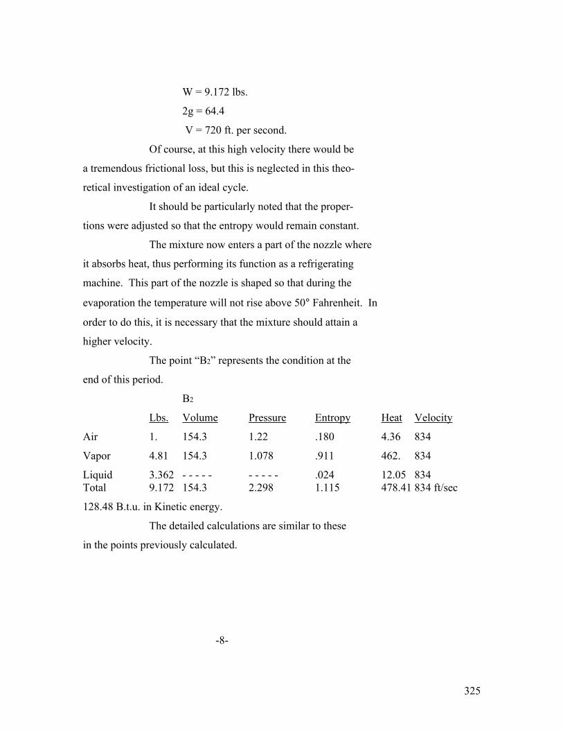
325
W = 9.172 lbs.
2g = 64.4
V = 720 ft. per second.
Of course, at this high velocity there would be
a tremendous frictional loss, but this is neglected in this theo-
retical investigation of an ideal cycle.
It should be particularly noted that the proper-
tions were adjusted so that the entropy would remain constant.
The mixture now enters a part of the nozzle where
it absorbs heat, thus performing its function as a refrigerating
machine. This part of the nozzle is shaped so that during the
evaporation the temperature will not rise above 50° Fahrenheit. In
order to do this, it is necessary that the mixture should attain a
higher velocity.
The point “B2” represents the condition at the
end of this period.
B2
Lbs. Volume Pressure Entropy Heat Velocity
Air 1. 154.3 1.22 .180 4.36 834
Vapor 4.81 154.3 1.078 .911 462. 834
Liquid 3.362 - - - - - - - - - - .024 12.05 834 Total 9.172 154.3 2.298 1.115 478.41 834 ft/sec
128.48 B.t.u. in Kinetic energy.
The detailed calculations are similar to these
in the points previously calculated.
-8-

326
At the beginning of the refrigeration period
“B1”, the mixture had a total energy content of 119.34 B.t.u. in
heat and 94.61 B.t.u. in Kinetic energy, making a total of 213.95
B.t.u. At the end of the refrigerating period, “B2”, the mixture
has an energy content of 478.41 B.t.u. in heat and 128.48 B.t.u.
in Kinetic energy, making a total of 606.89 B.t.u. Therefore, the
heat absorbed during the refrigerating process must have been
392.94 B.t.u.
The mixture now enters the third part of the
nozzle between “B2” and “B3”, which is shaped so that the Kinetic
energy will be transferred into static pressure. Neglecting fric-
tion, etc., it is theoretically possible to make this change at
constant entropy. The point “B3” represents the conditions after
this change has been completed.
B3.
Lbs. Volume Pressure Entropy Heat
Air 1. 28.2 7.7 .0880 22.34
Vapor 4.185 28.2 7. .8940 514.
Liquid 3.357 - - - - - - - - .1340 70.5 Total 9.172 28.2 14.7 1.1160 606.89
It will be noted that the energy content,
605.89 B.t.u. remained constant and that the entropy, 1.116, also
remained constant during this change, but that the pressure rose
to 14.7 lbs. absolute and the temperature rose to 128.4° Fahren-
heit. It is assumed that the mixture has lost its velocity as
-9-
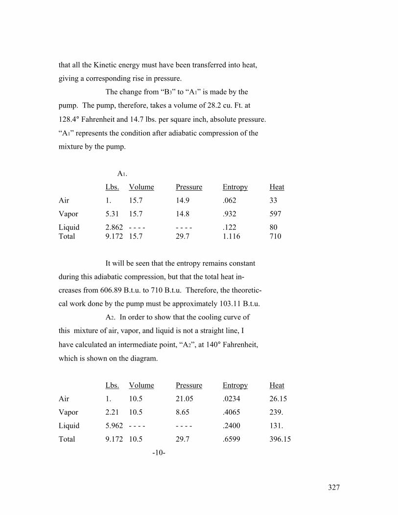
327
that all the Kinetic energy must have been transferred into heat,
giving a corresponding rise in pressure.
The change from “B3” to “A1” is made by the
pump. The pump, therefore, takes a volume of 28.2 cu. Ft. at
128.4° Fahrenheit and 14.7 lbs. per square inch, absolute pressure.
“A1” represents the condition after adiabatic compression of the
mixture by the pump.
A1.
Lbs. Volume Pressure Entropy Heat
Air 1. 15.7 14.9 .062 33
Vapor 5.31 15.7 14.8 .932 597
Liquid 2.862 - - - - - - - - .122 80 Total 9.172 15.7 29.7 1.116 710
It will be seen that the entropy remains constant
during this adiabatic compression, but that the total heat in-
creases from 606.89 B.t.u. to 710 B.t.u. Therefore, the theoretic-
cal work done by the pump must be approximately 103.11 B.t.u.
A2. In order to show that the cooling curve of
this mixture of air, vapor, and liquid is not a straight line, I
have calculated an intermediate point, “A2”, at 140° Fahrenheit,
which is shown on the diagram.
Lbs. Volume Pressure Entropy Heat
Air 1. 10.5 21.05 .0234 26.15
Vapor 2.21 10.5 8.65 .4065 239.
Liquid 5.962 - - - - - - - - .2400 131.
Total 9.172 10.5 29.7 .6599 396.15
-10-
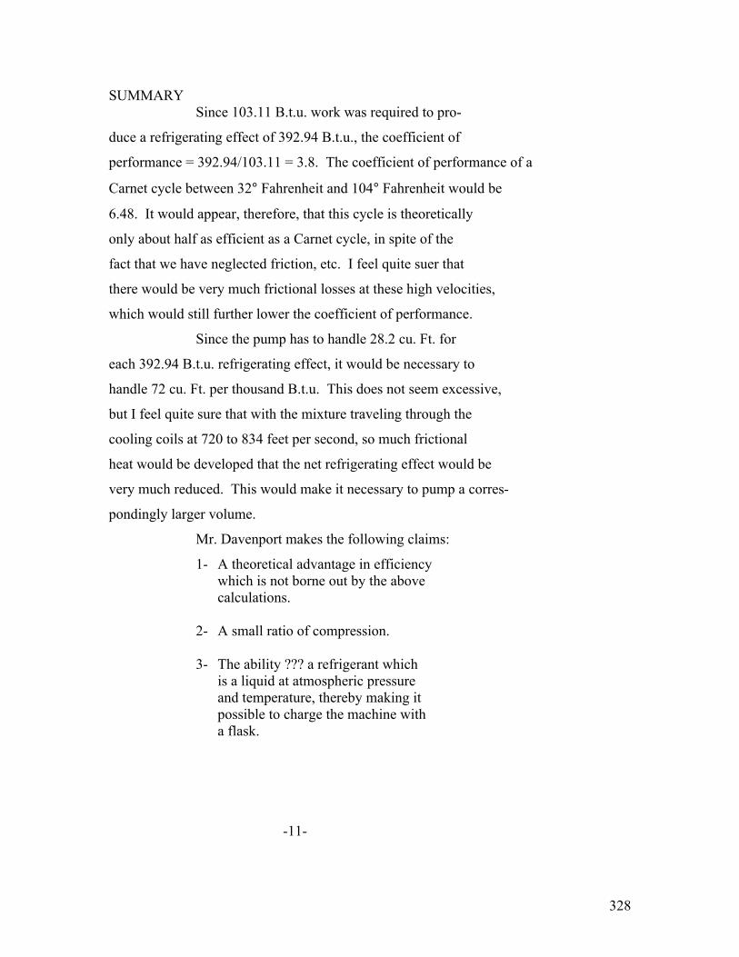
328
SUMMARY Since 103.11 B.t.u. work was required to pro-
duce a refrigerating effect of 392.94 B.t.u., the coefficient of
performance = 392.94/103.11 = 3.8. The coefficient of performance of a
Carnet cycle between 32° Fahrenheit and 104° Fahrenheit would be
6.48. It would appear, therefore, that this cycle is theoretically
only about half as efficient as a Carnet cycle, in spite of the
fact that we have neglected friction, etc. I feel quite suer that
there would be very much frictional losses at these high velocities,
which would still further lower the coefficient of performance.
Since the pump has to handle 28.2 cu. Ft. for
each 392.94 B.t.u. refrigerating effect, it would be necessary to
handle 72 cu. Ft. per thousand B.t.u. This does not seem excessive,
but I feel quite sure that with the mixture traveling through the
cooling coils at 720 to 834 feet per second, so much frictional
heat would be developed that the net refrigerating effect would be
very much reduced. This would make it necessary to pump a corres-
pondingly larger volume.
Mr. Davenport makes the following claims:
1- A theoretical advantage in efficiency which is not borne out by the above calculations.
2- A small ratio of compression. 3- The ability ??? a refrigerant which
is a liquid at atmospheric pressure and temperature, thereby making it possible to charge the machine with a flask. -11-

329
4- The fact that any leakage of air
into the machine is an advantage rather that a disadvantage.
On the other hand, Mr. Davenport has not yet
perfected the machine mechanically and we foresee the following
possible difficulties:
1- The volume to be pumped per thousand B.t.u. would be at least 72 cu. Ft., as compared with approximately 30 cu. Ft. for sulphur dioxide in our type OC-2 machine. Therefore, the pump would probably be more expensive.
2- We imagine that quite a complicated
carburetor would be necessary in order that the mixture going to the nozzle would have the proper propor- tions of air, vapor, and liquid.
3- The design and construction of the
expansion nozzle might be quite difficult.
4- Mr. Davenport has urged the advantage
that the refrigerant can be resupplied easily from a flask. We feel that the type OC-2 machine, which is Hermetically scaled, will never require any resupply of gas.
Mr. Davenport suggests the following theoretical ideas for consideration:
1- A difference between a perfect gas and a mixture of saturated vapor and a gas.
2- Probable alteration of latent heat
due to the attenuation of the liquid into films a few molecules thick, (Text Illegible) air and vapor.
-12-

330
3- He believes that the evaporation temperature at a certain pressure is lower when thoroughly aerated because, “The temperature of a body of liquid of a given tonsil strength is limited only by the density of its own vapor in its surface contact layer.” (SEE DIAGRAM ( Illegible))

331
THE DETROIT EDISON COMPANY General Offices 2000 Second Ave. Detroit, Michigan August 8, 1923.
Mr. A. R. Stevenson, Jr., Power & Mining Engineering Dept., General Electric Company, Schenectady, N.Y. Dear Mr. Stevenson: - Now that you have, through the mediation of my company, been given full and complete information on the Davenport refrigerating process, you will, perhaps, judging from your con- versation Saturday, act much as I would under similar conditions and proceed along the following lines:
1. I would immediately confirm, both by my own efforts and by consultations with my associates, the breadth and soundness of the principles of the process.
2. I would then, for an indefinite period, waste time, perchance endeavoring to think up some way to safely take ad- vantage of the information given me with the object of evading the inventor’s claims – or, in your words, “try to do the same thing another way.”
3. Eventually I might find myself wondering whether it would be cheaper to take a chance on making the things and fight- ing, or purchasing the invention. But I didn’t have a chance to talk with you alone at any time or I would have given you this further information which I am sure will direct your decisions. I have been present with Mr. Davenport at a number of recent conferences, some of them arranged by me because of my interest in domestic refrigeration for a number of years as a public utility problem, and the follow- ing groups are interested either as prospective manufacturers or users: (1) A man from New York directly representing Chase N. Schwab, (2) Mr. Carrier of the Air Conditioning Company, (3) National Ice Association (represented by the president and vice- president of the General Ice Delivery Company of Detroit), and (4) The General Electric Company, (Text Illegible) the Ice Association held the strongest hang, with Mr. Schwab coming along ascend. In a scrap either of these would be hard to

332
(2) A. R. Stevenson, Jr. August 8, 1923. beat, but I am sure it will not come to that. It is not neces- sary to tell you why we would prefer not to have this in the hands of the Ice Companies. I don’t know whether you know, but I have been told several times, and again in this recent conference with the Ice crowd, that they have had for a number of years, like the German General Staff, a plan worked out which they would pursue if the right domestic machine came along and reached their con- troll. That plan is to make the machine by the thousands and the various number companies, local ice concerns, would act as dealers. The machine would be put in your house on a rental basis of just enough to cover fixed costs and give a good healthy profit selling the machine eventually, also at a good profit, when the customer had learned by experience that the machine was right. They would, of course, include service and continue the rental policy where the customer didn’t wish to buy. The user would, of course, pay for the current consumed. Analyzing that you’ll find it isn’t such a bad plan. Manufacturers of some of our well known machines tell me they can manufacture their machine for $70.00. Now if that is true, Davenport’s can be made for $30 to $40, or less. Let us assume that this ice company purchasing machines by the thousand could place on in domestic ice boxes for $100, where before these users had averaged $5.00 a month for ice. The customer will at once have an increased electric bill ranging from $15 to $25 per year depending on the rate. In addition to this he will have to pay the ice company $15 per year to cover fixed costs and something for service and profit. So it looks as though the ice company could continue to pay good dividends even if the user spent no more than originally spent for ice. But, of course, he would be willing to pay more. Now my idea is that this is a public utility problem, that we are better fitted to give this kind of service than the ice companies, we already have the necessary service organization for such a simple machine, and that we should borrow their plan for distribution. But we cannot do this if this has companies control the situation. Hence, we want to see the thing manufactured by one of the big electric companies.

333
Now, if you decide that Davenport’s machine is right in principle, and a couple of days should, with the eminent advisors available, enable you to do this, it follows that the domestic refrigerating problem is solved and the exploitation of (3) A. R. Stevenson, Jr. August 8, 1923 this field is immediately available to you. If you do decide this, I believe it is for the best interests that you enter into at least tentative negotiations and thus get in line on it this week. Your very truly, THE DETROIT EDISON COMPANY A. D. MoLay Sales Engineer Copies to Miss S. M. Sheridan, Vice President & Sales Manager, The Detroit Edison Company. Mr. T. D. Crocker, Chairman, Associated Edison Committee on Domestic Refrigeration. P.S. Mr. Davenport just phoned me that he will leave Monday for York, Pa., with Mr. Hayes of the General Ice Company. Couldn’t you wire him to call at Schenectady on the way back?

334
GENERAL ELECTRIC COMPANY _____ Internal Correspondence Mr. Davenport’s Scheme for Domestic Refrigeration. DETROIT – August 22, 1923 Mr. A. R. Stevenson, Jr., Power & Mining Engr. Dept., SCHENECTADY.
I thank you for your August 20th
letter with the attached report concerning this
domestic refrigeration scheme.
We will get in touch with the
necessary people in the Detroit Edison Company and
convey to them the information that we are not interest-
ed in the purchase of this refrigeration scheme.
Yours very truly,
SM DEAN
ASSISTANT MANAGER.
SMD.VB.

335
APPENDIX NO. 18.
PARTIAL LIST OF PEOPLE CONSULTED BY INTERVIEW OR CORRESPONDENCE.
- - - - - - - - - -
The following is a partial list of people who have
been consulted either by interview or correspondence.
Mr. Henshaw’s office was of special assistance in
looking up the information concerning the competing machines
and the capitalization of the competing companies.
Mr. Blake and Mr. Dalton furnished very valuable
advice as to the proper method of conducting the investigation.
Mr. Goll, Mr. Wood, Mr. Evans, Mr. Crane, Mr. Orr and
Mr. Givens of the Ft. Wayne Works, all furnished assistance in
the preparation of the report.
Mr. Bows ad Mr. Blakeman of the Commercial Service
Section of the Publication Bureau prepared a report covering
a publicity plan for domestic refrigeration, electric type,
which furnished a general idea of the cost of advertising.
Advertising Department, (F.R.Davis.)
American Society Refrigerating Engineers.
American Washing Machine Manufacturers Association.
Mr. G. W. Alder, Engr. Of the Good Housekeeping
Institute.
336
Mr. Barber, Merchandising Dept. of the Western Electric Co.
Mr. A. K. Bayler.
Dr. E. J. Berg.
Mr. S. H. Blake
Mr. D. L. Boyd (Mr. Henshaw’s Office).
Mr. W. J. Bray (Salesman handling Refrigeration Industry
in Chicago Office.)
Bureau of Standards
Mr. H. E. Bussey, Engineer Atlanta Office.
Mr. C. C. Chesney (who has a Coldak machine in his house)
Mr. F. P. Coffin (Research Laboratory)
Mr. R. N. Cole, Refrigerating Engineer.
Commercial Service Section of the Publication Bureau
(W. A. Bowe).
Mr. H. E. Crane, Mgr. Ice Machine Dept., Ft. Wayne Works.
Mr. T. D. Crocker, Minneapolis Light & Power Co.
Mr. G. W. Crossett (Salesman handling Refrigeration Industry
in the New York Office).
Mr. Neil Currie, Jr.
Mr. William Dalton.
Mr. A. P. Danz, Industrial Control Specialist.
Mr. C. Dansizen, Research Laboratory.
Mr. R. W. Davenport, Inventor.
Mr. M. C. Davison, Ingersoll-Rand Co.
Mr. J. G. DeRemer, Consulting Engineer, Savage Arms Co.
Department of Agriculture.
Mr. A. R. Dodge, Flow Motor Department.

337
Mr. Donahue, Former Service Man for the Isko Company,
Mr. Dwelly, Vice President of the Kelvinator Company.
Mr. Dwight, Society for Promotion of Electrical Development.
Mr. A. L. Ellis, Thompson Research Laboratory.
Dean Edward Ellery, Union College.
Engineering News Record.
Engineering Standards Committee.
Mr. H. F. T. Erben.
Mr. Sam Ferguson, Hartford Electric Light & Power Company.
Mr. G. T. Fielding, Director Commercial Research of
Bridgeport Works.
Fire Department, New York City.
Mr. Fischer, Vilter Company.
Mr. Fisher, Hurley Washing Machine Company.
Professor D. L. Fisk, University of Illinois.
Mr. A. J. Francis, Mgr. Practional Horse Power Dept.
Mr. Gardner, Statistician of the Western Electric Co.
Mr. Garrison (In charge of refrigeration for the
Ingersoll-Rand Co.)
Mr. W. S. Goll.
Mr. Grant, President of the Delco Light Co. manufactur-
ing Frigidaire.
Professor A. M. Greene, Princeton University.
Mr. V. R. Greene, Consulting Engineer.
Mr. A. C. Greenwood, Edison Illuminating Co., Boston.
Mr. Givens, Ft. Wayne Works.
Mr. A. W. Henshaw

338
Mr. J. R. Hewett.
Mr. N. H. Hiller, President of the Carbondale Company.
Mr. W. J. Hanley.
Hibbard Company, Agents in Cleveland for the Kelvinator
Corporation.
Mr. T. I. Jones, Brooklyn Edison Company.
Mr. D. F. Keith, President Keith Electric Refrigeration
Company.
Mr. F. M. Kimball.
Mr. Koken, Refrigerating Engineer.
Mr. Kossats, Service Mgr. Of the Frigidor Company.
Mr. N. J. Kingsbury.
Dr. Langmuir.
Mr. Lawrence, of the Firm of Thomas Murray, Consulting
Engineers.
Mr. Loffell, Pilsbury Becker Company.
Mr. N. McA, Lloyd, Consulting Engineer.
Mr. I. Lungard, of the Automatic Refrigeration Co.,
Inventor of the Odin.
Professor MacIntyre, University of Illinois.
Mr. D. J. M’Nulty, American Balsa Company.
Mr. J. F. McManus, Director of the Glacifer Company.
Mr. A. C. McLay, Sales Engineer, Detroit Edison.
Mr. L. S. McCormick, President of the MacLaren Frozen
Air Company.
Mr. P. L. Miles, Edison Electric Appliance Co.
Mr. G. E. Miller, Cleveland Edison Co.
Mr. Miller, Servel Company.
339
Mr. J. P. Morash, General Manager of the Lipman
Company
Dr. S. A. Moss, Thompson Research Laboratory
Mr. J. F. Myrick, Salesman for refrigerating apparatus
in the Baltimore Office.
Mr. C. R. Neeson, Consulting Engineer (formerly
engineer of the Knickerbocker Ice Co.)
Mr. C. K. Nichols, New York Edison Company.
Mr. J. E. North, Secretary of the Electric League of
Cleveland.
Mr. Oettli, Publication Bureau, General Electric Co.,
Paris, France.
Mr. Clark Orr, Engineer Ice Machine Dept., Ft. Wayne
Works.
Mr. Stuart Otto, President of the Hall Borchert Co.
which manufactures a domestic
refrigerating machine.
Mr. K. A. Pauly.
Mr. M. E. Pennington, Engineer investigating domestic
refrigeration for the National
Association of Ice Industries.
Mr. K. D. Perkins, Engineer of the Audiffren Company.
Mr. C. F. Pittman, Industrial Control Department.
Mr. Rae, Western Electric Company.
Mr. C. E. Reddie, Western Electric Company
(In charge of their investigation of
domestic Refrigerating apparatus)
Mr. Willard Reid, President of the Coldak Company.
340
Mr. E. L. Rich, Patent Department.
Mr. A. F. Riggs, Assistant Engr., Chicago Office.
Mr. H. J. Riffel (In charge of the service of the
type OC-2 machines on consignment
in Schenectady.)
Mr. J. F. Roche (In charge of advertising for the
Edison Electric Appliance Co.
Mr. Rogers, Sauter Company.
Mr. Paul Schlingman, Salesman in charge of Refrigeration
Industry in the St. Louis Office.
Mr. E. B. Seitz, Secretary American Association of
Washing Machine Manufacturers.
Mr. J. A. Smith.
Mr. E. B. Smith, Industrial Control Specialist,
Cincinnati Office.
Mr. Sorren, Hartford Electric Light Company.
Dr. Steinmetz.
Mr. T. K. Stevenson, Western Electric Company.
Mr. C. W. Stone.
Superintendents of Water Works in eighty-one cities.
Professor Elihu Thompson.
Mr. C. K. Trip of the Lynn Works.
Washington State College.
Mr. E. G. Waters.
Mr. D. W. Weed (Who make a report previously on this
same subject).
Mr. E. T. Williams, President of the Williams Simplex
Refrigerating Company.
341
Mr. Wilson, Salesman for the Frigidair in the
Albany District.
Mr. J. J. Wood, Ft. Wayne Works.
Mr. Zimmerman (Formerly Service Man for the Carbonic
Machine Company).

342
APPENDIX NO. 19
LIST OF MANUFACTURERS DESIRED EITHER BY MR. STEVENSON
OR MR. CRANE.
- - - - - - - - - - -
The following is a partial list of manufacturers of
domestic refrigerating machines which have been personally
investigated by either Mr. Crane or Mr. Stevenson. A great
many of the other machines listed in the appendixes have
been investigated by representative of Mr. Henshaw or members
of General Electric Company Local Offices.
M. B. Arnold.
The American Balsa Company.
The Audiffren Company.
The Autofrigo Company
(Sample machine tested by Mr. H. E. Crane)
The Coldak Company.
Common Sense Ice Machine Company.
The Copeland Company.
The Federated Engineers Development Corporation.
The Freezerator Company.
The Frigidaire Company.
The Frigidor Company.
The Glacifer Company.
The Havenstrite Company.
George Horawa Company.
The Isko Company.
343
The Kelvinator Company.
Professor Keyes Machine.
The Lipman Company.
Mac Laren Frozen Air Corporation.
The Horwalk Company.
The Odin Company.
Savage Arms Company.
The Servel Company.
Universal Company.
Utility Ice Machine Company.
Williams Simplex Refrigerator Company.

344
Appendix 20 M.V. ARNOLD’s MACHINE *************
(1) Some of manufacturer – Mr. M. V. Arnold.
(2) Address – Furniture Building, Evansville, Indiana.
(3) Resources - ?
(4) Model – There is only one model.
(5) Size motor – 1/8 H.P. with water condenser at 40 lbs.:
or, on ¼ H.P., with air condenser at 80 lbs.
(6) Cubic contents – 15 cu. Ft.
(7) Automatic or non-automatic – Automatic.
(8) Place where machine is mounted – it can be located in or away from the ice box any reasonable distance without pipe insulation.
(9) Model temperature of ice box – 40 degrees Fahrenheit.
(10) Refrigerant used - ?
(11) Is there a stuffing box – No.
(12) Air cooled or water cooled – Water.
(13) Compressor – One cylinder.
(14) Brine tank used or direct expansion – Brine tank.
(15) Detail net price to user- ?
Mr. Arnold says that the machine could be manufactured for $75.00 on a production of ten a day.
(16) Average hours operated per day – 9 hours.
(17) Guarantee – Unknown.
(18) Service – No arrangements have been made for servicing this machine, as Mr. Arnold has made only the one machine.
Remarks:
(Text illegible) Mr. H. E. Crane, of the Fort Wayne Office:
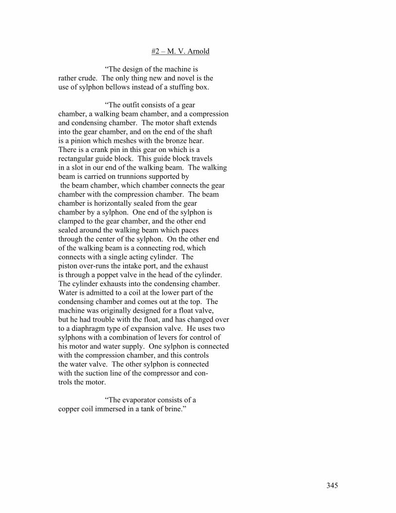
345
#2 – M. V. Arnold “The design of the machine is rather crude. The only thing new and novel is the use of sylphon bellows instead of a stuffing box. “The outfit consists of a gear chamber, a walking beam chamber, and a compression and condensing chamber. The motor shaft extends into the gear chamber, and on the end of the shaft is a pinion which meshes with the bronze hear. There is a crank pin in this gear on which is a rectangular guide block. This guide block travels in a slot in our end of the walking beam. The walking beam is carried on trunnions supported by the beam chamber, which chamber connects the gear chamber with the compression chamber. The beam chamber is horizontally sealed from the gear chamber by a sylphon. One end of the sylphon is clamped to the gear chamber, and the other end sealed around the walking beam which paces through the center of the sylphon. On the other end of the walking beam is a connecting rod, which connects with a single acting cylinder. The piston over-runs the intake port, and the exhaust is through a poppet valve in the head of the cylinder. The cylinder exhausts into the condensing chamber. Water is admitted to a coil at the lower part of the condensing chamber and comes out at the top. The machine was originally designed for a float valve, but he had trouble with the float, and has changed over to a diaphragm type of expansion valve. He uses two sylphons with a combination of levers for control of his motor and water supply. One sylphon is connected with the compression chamber, and this controls the water valve. The other sylphon is connected with the suction line of the compressor and con- trols the motor. “The evaporator consists of a copper coil immersed in a tank of brine.”
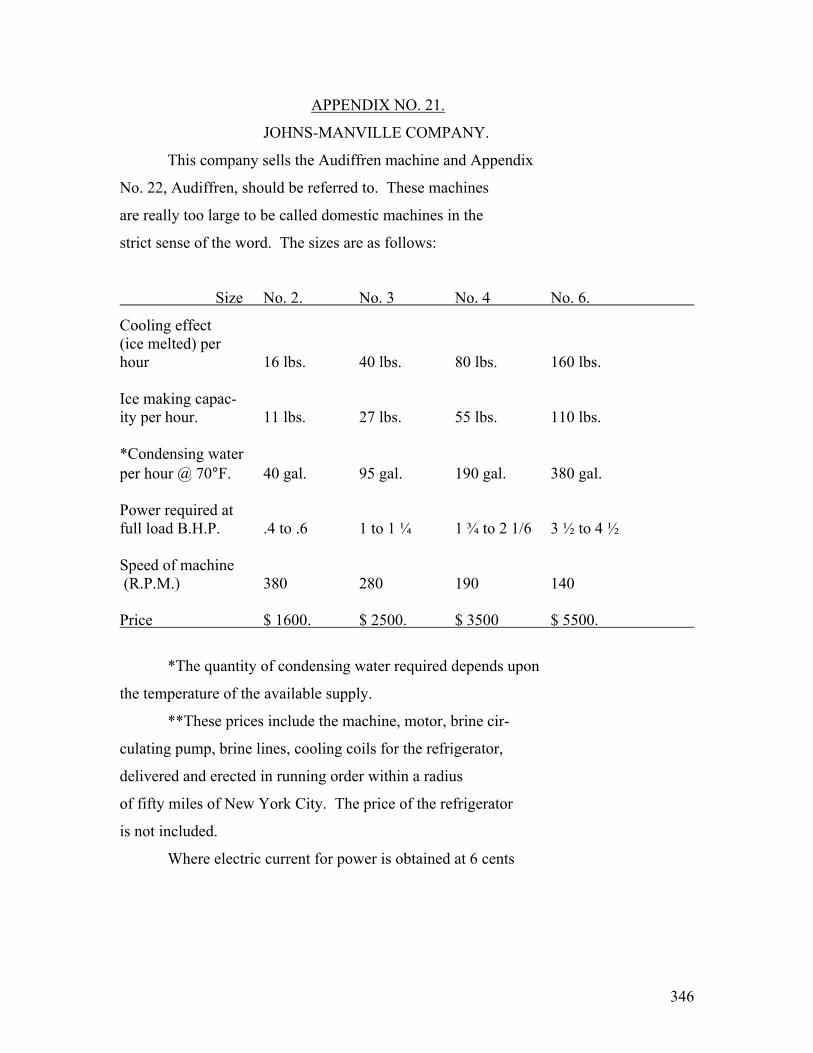
346
APPENDIX NO. 21.
JOHNS-MANVILLE COMPANY.
This company sells the Audiffren machine and Appendix
No. 22, Audiffren, should be referred to. These machines
are really too large to be called domestic machines in the
strict sense of the word. The sizes are as follows:
Size No. 2. No. 3 No. 4 No. 6.
Cooling effect (ice melted) per hour 16 lbs. 40 lbs. 80 lbs. 160 lbs. Ice making capac- ity per hour. 11 lbs. 27 lbs. 55 lbs. 110 lbs. *Condensing water per hour @ 70°F. 40 gal. 95 gal. 190 gal. 380 gal. Power required at full load B.H.P. .4 to .6 1 to 1 ¼ 1 ¾ to 2 1/6 3 ½ to 4 ½ Speed of machine (R.P.M.) 380 280 190 140 Price $ 1600. $ 2500. $ 3500 $ 5500.
*The quantity of condensing water required depends upon
the temperature of the available supply.
**These prices include the machine, motor, brine cir-
culating pump, brine lines, cooling coils for the refrigerator,
delivered and erected in running order within a radius
of fifty miles of New York City. The price of the refrigerator
is not included.
Where electric current for power is obtained at 6 cents

347
per K.W. hour, and condensing water at $1.00 per 1,000 cubic
feet, these machines will furnish refrigeration at from
16 cents to 22 cents per hundred pounds of refrigerating
effect.
The Johns-Manville Company make the statement that
the Refrigerator Box can be held 10 to 15 degrees colder
than when ice is used.
In case the reader is not familiar with the Audiffren
machine, the following brief description may be of interest.
The machine looks like a large dumbbell. One end of
the dumbbell contains a two cylinder double acting compressor
which hangs on a lead weighted pendulum. The gas is
compressed by this compressor and the heat of condensation
is taken away by cooling water in which that end of the
dumbbell revolves. The liquid sulphur dioxide goes through
an expansion valve and through the hollow shaft to the other
end of the dumbbell where it evaporates. This evaporation
absorbs heat from the brine in which the expansion dumbbell
is immersed.
These dumbbells are completely sealed up and the
chance of leakage of the refrigerant is thereby very much
reduced. Some of these dumbbells have been in operation
for eleven years without being opened.
The dumbbells are mounted in bearings and are
revolved by a belt from a motor. As the dumbbells revolve
the compressor with the pendulum hangs stationary and is

348
operated by the revolution of the dumbbell.
Appendix No. 1 shows that only 5% or 6% of these
dumbbells are ever returned for repairs. The chief
difficulty has been due to the fact that in case the cooling
water supply is shut off, the pressures build up and the
compressor with its pendulum instead of hanging stationary,
turns over with the dumbbell. This causes an unbalance
which bends the shaft. Incidentally, this is a safety
feature because it prevents the machine from blowing up.
The machine includes a centrifugal unloading device
which equalizes the pressures in the compressor cylinders
and allows the motor to start up easily.
There is also quite a complicated oiling system which
insures a circulation of oil through the machine.
The dumbbells are made of special navy bronze and are
carefully tinned. This tinning operation fills in the pores
in the casting which might cause a leak. There is only
about one machine a year returned on account of leaks.
In all the years the General Electric Company have been
manufacturing these machines, there have only been one or
two valve springs broken.
The expansion valve is of the float type.
There is a special (illegible text) the
gas in the expansion bell and scoops up the oil so that

349
it will be returned with the gas to the suction side of
the compressor. The expanded gas is sucked back through
the large tube in the hollow shaft, whereas the liquid goes
from the compressor bell to the expansion bell through a
small tube down the center of the shaft.

350
APPENDIX NO. 22.
AUDIFFREN.
1. Name of Manufacturer – Audiffren Refrigerating & Machine
Company.
2. Address – 90 West Street, New York City.
3. Resources – This concern has an authorized capital
of One Million Six Hundred Thousand Dollars, ($1,600,000.)
and Two Hundred Thousand Dollars, ($200,000) of this was
issued at par in 1911.
4. This company was organized by Mr. Griscom about 1911
and purchased the American rights to the Audiffren patents
from the Singrun Company. They arranged with the General
Electric Company to manufacture these machines and with the
Johns-Manville Company to sell them. The contract between
the Audiffren Company and the General Electric Company con-
tained the following paragraph:
“First, the factory cost is to be computed on the basis
in use from time to time by the General Electric Company
at its factory where said machines are manufactured
(the additions to direct labor to cover overhead charges
no to exceed 100% on direct labor and not to exceed
5% on material) but not including any development.
To the figure thus obtained is to at added twenty five
percent (25%), and to the total thus arrived at is
to be added ten percent (10%) and to this is to be
added development at cost as ascertained by the

351
methods in use from time to time at the said factory.
“Nothing herein contained shall operate as an admission
by the General Electric Company of the ownership, scope or
validity of any patent or patent rights owned or claimed
by the Refrigerating Company, nor shall anything herein
contained be construed as restricting the right of the
General Company to make, use and sell to others to be sold
and used, refrigerating machines of any design or construction
whatsoever except the Audiffren machines of this contract,
provided however that should the General Company manufacture
and sell refrigerating machines competing with the Audiffren
machine in the same capacities, then and in that case the
Refrigerating Company shall have the right to terminate
this agreement by sixty days notice in writing served on the
General Company to that effect.”
Appendix No. 1 shows that the overhead on the present
manufacture of the Audiffren machine at our Ft. Wayne factory
greatly exceeds 100%. This business is, therefore, no
longer attractive to the General Electric Company unless the
volume can be increased and the contract changed.
It is interesting to note that the smallest size
Audiffren machine is rate at 100 lbs. of ice in twenty-four
hours, whereas the Ft. Wayne type O.C.-2 domestic refrigerating
machine has a capacity of considerably less that 200 lbs. of
ice in twenty-four hours. Originally all these Audiffren

352
machines were water cooled and were sold through the Johns-
Manville Company. For a description of them see Appendix
No. 21, Johns-Manville.
5. Comparatively few of the Audiffren machines have been
sold for use on domestic refrigerating installation because
of the large floor space required, the excessive weight and
the open condenser which combine to make a serious installation
problem.
6. Two of the important patents on the Audiffren machine
are No. 1,155,780 which does not expire until October 5, 1932,
and No. 1,424,826 which covers the automatic control and was
issued Aug. 8, 1922.
7. Recently the Audiffren Company has developed an air cooled
machine. Our Ft. Wayne factory furnished them a No. 2 size
of two cylinders, thus reducing the capacity. The Audiffren
Company have soldered on copper fins to the dumbbells in order
to avoid water cooling and a brine tank. A rotary motion
of the dumbbells furnishes a fan action so that the heat
transfer is very good. When the room temperature is 110
degrees Fahrenheit, the condenser pressure was only 89 lbs.
The dumbbell will be installed (illegible text)
the fans on the expansion end will suck the warm air in at the bottom.
The input to the motor is 300 watts and it runs about

353
half the time when refrigerating a refrigerator having 12 cu.
Ft. food storage capacity.
8. Mr. Perkins, the engineer of the Audiffren Company,
gave me the following list of costs:
Dumbbell - - $ 200.00
12 cu. Ft. Refrigerator - - 200.00
1/5 HP motor - - 26.00
Bearings - - 15.00
Base - - 25.00
Idler - - 10.00
Copper in fins - - 18.00
Soldering copper fins 10.00
Thermostat and Starter 30.00
Assembly - - 41.00
Total Cost - - $ 575.00
Probable selling price, approx. $ 900.00 Note: For description of the water cooled machines, attention is again called to the Appendix No. 21, Johns-Manville.

354
Appendix 23 AUTOFRIGOR ********
(1) Name of manufacturer – Escher Wyss & Co.
(2) Address – Zurich, Switzerland.
(3) Resources - ?
(4) Models – A-301 A-501
(5) Size motor - 1/4 H.P. 0.35 H.P.
(6) Cubic contents - 14 cu. Ft. 25 cu. Ft
(7) Dimensions: See catalogue Data Folder #704
Weight - 360 lbs. 480 lbs. (without refr.) (without refr.)
(8) Ice Making – 5 to 10 lbs. ice 8 – 16 lbs. ice daily daily
(9) Place where machine is mounted – in top of refrigerator.
(10) Automatic or non-automatic – Literature describes no automatic control.
(11) Usual temperature of ice box - 35° to 40°
(12) Refrigerant used – Methyl chloride.
(13) Is there a stuffing box – No No
(14) How often resupplied - Never Never
(15) Is gas considered dangerous or not – Not (See appendix on refrigerants.)
(16) Safety shut-off – None mentioned.
(17) Air or water cooled - Water Water
(18) Water per day - 13 gals. Per hour 13 gals per hour
(19) Compressor – One double acting, oscillating cylinder, 1400 RPM.

355
#2 - Autofrigor
(20) Brine tank used for direct expansion – Brine for ice, but Apparently direct expansion for cooling.
(21) Detail net price to user – Unknown.
(22) Percent discounts to deplore – Unknown.
(23) Average hours operated per day – 6 to 10.
(24) Estimated KW-hours per day – 1.5 to 2.5.
(25) Guarantee – Unknown.
(26) Second hand business – Unknown.
(27) Service – The Escher Wyss & Co., will manufacture this machine in Switzerland for exploitation to the United States because the offers they received from America did not come up to their expectations. They will organize a special sales organization for these machines in the United States, and after they have been successfully introduced on the American market they will make arrangements for their manu- facture over here.
Remarks:
This machine is almost identical with our Fort Wayne OC-2 machine. The chief differences are
as follows:
a- The stator of the motor is outside the machine and the power is transmitted magnetically through a thin metal diaphram of non-magnetic material of high electrical resistances situated in the air gap of the motor, forming a seal around the rotor. Our Fort Wayne engineers tested one of these machines and prepared technical report #15201, and they point out that this metal diaphram in the air gap heats up very badly. Of course, the Swiss engineers may have recently discovered a more high resis- tance material in which the eddy current losses would be less.
b- The brine tank of this machine is corrugated. This is theoretically and advantage because it gives a larger area for absorbing heat. There is danger that this construction would be more expensive than our present smooth tanks. Mr. Bosworth said that the Escher Wyss Company sent seven Autofrigor machines to this country.

356
#3 – Autofrigor The principal advantage of the Autofrigor is that it has no packing whatsoever, as the whole pump and all moving parts are enclosed in the ice machine itself. For this purpose the rotor is surrounded by a very thin sheet of special metal. A special lubrication system for the motor as well as for the compressor pump is applied. Another essential part of the Autofrigor is the device to prevent the nozzles from freezing: there is also a special device to indicate if the rotor is revolving or not.

357
Appendix 24 BAUER & WAHL ******* (1) Name of Manufacturer – Bauer & Wahl, Engineers and Contractors.
(2) Address – Place Kleber, Strasbourg.
(3) Resources - ?
(4) Models – Three (4000, 8000, and 12,000 frigories per hour)
Remarks:
The advertisement says that this machine is of the Linde system. The picture looks like a small size ammonia installation. It looks more like a butcher shop rather than a domestic machine.
358
Appendix 25 BRUNSWICK ********
Mr. Danz, the industrial control specia-
list of the New York Office, said that Major Holmes of
the firm of Miller, (illegible text), Hutchinson, had invented a
domestic refrigerating machine in which there is no
stuffing box because the piston is pushed through a
sylphon bellows. Mr. Danz understood that the Brunswick
Company had taken this up.
Ed note: this may have been manufactured under the tradenames Holmes and Allison
359
Appendix 26
CHILRITE
**************
(1) Name of manufacturer – Winter Machine Company
(2) Address – Pawtucket, Rhode Island.
(3) Resources – This concern has an authorized capitol of $200,000.00.

360
Appendix 27
COLDAK ***********
(1) Name of Manufacturer – The Coldak Company.
(2) Address – 40 Napier Street, Springfield, Mass.
(3) Resources – Paid in capital, $36,000.00; manufacturing capacity, $150,000.00; output in 1922, $100,000.00 This Company have sold three hundred machines and are building four hundred more now. They have several orders for about fifty machines for apartment houses. They have just received one large order for 398 machines to one company, 374 for one apartment house, and 24 for another. They are making about six machines a day. The machine was put out commercially in June, 1922, and some of them have ran ever since without and atten- tion. Mr. C. O. Chesney, manager of the Pittsfield Works, is very much pleased with one that he put in last October. The following is quoted from a letter from Mr. Wm. Reid, president of the Coldak Company: “We regret very much that we are not in a position to make any further sales con- nections at this time, as we have been very much over-sold for the past eight months in spite of substantially increased production facilities. “We are now laying plans for still greater production and expect to be in a position
within the next four months to extend our dealer connections.”
(4) Development -
(5) Models – “A” “B” “C”
(6) Size motor - ½ ¼ ?
(7) Cubic Contents- 20 – 40 cu. Ft. Not over ? 20 cu. Ft.
(8) Ice making at twelve and a half pounds of ice in just barely
sufficient to freeze two quarts of ice cream. This can be
obtained in five or six of the trays.
361
#2 – Coldak
They make about twenty pounds of ice per KW-hour: if the machine were water cooled, they might make six pounds of ice more.
(9) Automatic or non-automatic – Automatic. (10) Place where machine is mounted – in basement. (11) If thermostatic control, give range of temperature - 38° to
50°. (12) Usual temperature of ice box – They are willing to put their
machines in any ice box, but guarantee brine temperature and not degrees temperature. They try to keep the brine between 20 and 22 degrees Fahrenheit.
(13) Refrigerant used – Ethyl chloride.
Ethyl chloride has more B.t.u. per pound than anything except ammonia. It burns quite fiercely at any opening. It is very unlikely that enough would get into a room to cause an explosion. They furnish two pressure gauges on a machine at a total cost of about $1.50. All the valves are arranged so that a special wrench would be required so that a customer could not fool with it. When ethyl chloride burns, it gives off chlorine.
(14) Is there a stuffing box – Yes. The stuffing box is arranged with a spring
which gradually takes up the wear. This has to be tightened about once a year. The stuffing box on the Coldak machine is similar to the gland stuffing box on the Isko machine, which has worked well for years.
(15) How often resupplied – The Coldak company have not yet had long enough experience to know how often ethyl chloride must be renewed.
(16) Cost of new refrigerant - ? (17) Is gas considered dangerous or not – See appendix on
refrigerants.
362
#3 - Coldak
(18) Lubricant – They put a special oiling system on the motor with a tank large enough so that the oil only has to be renewed once every two years. Sometimes, if the machine is shut down for long, the oil becomes thin by being diluted with liquid ethyl chloride, alcohol and water. This thin oil does not make a good seal in the pump and sometimes the pump will not pump itself out. It is then necessary to shut off the supply of liquid to the expansion valve for about one-half hour. The machine will then pump a vacuum and get very hot. This vaporizes the ethyl chloride, leaving the oil somewhat thicker. Then, the supply of liquid to the expansion valve can be opened and machine will operate successfully.
(19) Air or water cooled – Air. (20) Compressor – Rotary.
This machine has a two stage herringbone gear rotary pump. In the past, the Isko Company and others have had rotary pumps, but they have been single stage and have operated with a differential of as high as 100 lbs. The pressures encountered with ethyl chloride run anywhere from 25 to 40 lbs. This is divided into two stages so that probably the explanation of their success. The gear wheels in the pump are especially
designed. Apparently there is about 2/1000 clearance. They have a spring coupling which allows the motor sufficient and play and also makes it easier for the motor to start the pump. On a damp hot day, the conduction and convec- tion from the box is greater, making more work for the ice machine. Their pump has so little clearance that it pumps the same amount of refrigerant in the hot weather as in cold weather. This was demonstrated by tests which they showed me. They have a hot room for testing their machines, which is heated electrically.
(21) Brine tank used or direct expansion – brine tank. (22) Retail net price to user - “A” “B” “C”
$325.00 $295.00 ??? (23) Percent discounts to dealers – At present, they give dealers
35 percent, the salesman getting 15 percent of this.

363
#4 – Coldak
(24) Does price include: Refrigerator - No No No Brine tank - Yes Yes Yes Installation - No No No The dealer makes a separate charge for delivery and installation.
(25) Average hours operated per day – 6 hours. Mr. C. O. Chesney, manager of the Pittsfield Works, says that the machine runs for about one hour and shuts down for three.
(26) Guarantee – “The COLDAK Company in lieu of all implied warranties hereby expressly agrees to correct any defects of labor or material in COLDAK machines which develop under normal and proper use within one year from the date of shipment thereof, provided the Purchaser gives the COLDAK company immediate written notice of
such defects.”
(27) Service – The Coldak Company showed me one machine which has been running for 4 ½ years and is still running very quietly.
They have no trouble with leakage from their stuffing box. They lead high pressure oil into the stuffing box and some oil comes out, but apparently no ethyl chloride gets outs. The originally had trouble with selective freezing and blocking the expansion valve. They have applied for a patent on adding three or four ounces of alcohol, which prevents the moisture from freezing very successfully. Once in a while, their machine has to be shut down over night in order to defrost. The melting of the frost carries away odors which have collected around the brine tank. A drain is necessary in order to carry away the melted frost. The Coldak Company say that Coldak machines are entirely dependable and automatic and do not require any
attention from the owner: they start and stop themselves, even the electric motor automatically oils itself and carries a two years’ supply of oil in the sight feed bottle.
364
Appendix 28 COLDMAKER ************
(1) Name of manufacturer – Toledo Coldmaker Company (2) Address – Toledo, Ohio.
(3) Resources = The paid in capital of this Company is $45,000.00.
and they have a manufacturing capacity of approximately $100,000.00, and distribute through jobbers.
(4) Size motor – Unknown. (5) Cubic contents – Is for installation in any box.
(6) Ice making – There is a compartment where ice can be made or
desserts frozen.
(7) Automatic or non-automatic – Automatic. Air or water cooled – water.
(8) Place where machine is mounted – The cooling coils and ice trays are installed in the ice chamber of the refriger- ator. The machinery is installed in the basement or other out-of-the-way place.
(9) If thermostatic control, give range of temperature – A vartiation
of two degrees from the desired temperature in the food compartment actuates the thermostat which starts or stops the compressor instantly.
(10) Refrigerant used – Ammonia. (11) How often resupplied – About seventy-five cents worth of
ammonia (one quart) will serve indefinitely.
(12) Is gas considered dangerous or not – Yes (See appendix on refrigerants.)
(13) Air cooled or water cooled – (14) Brine tank used or direct expansion – Brine tank. (15) Compressor – two cylinder, with pistons only 1 ¼ inches in
diameter.
(16) Retail net price to user – Unknown. (17) Percent discounts to central stations – Unknown.
365
#2 - Coldmaker
(18) Guarantee – Unknown. (19) Service – this machine has been built and sold for over
eight years. The following Coldmaker Company has been making and selling refrigerating machines for meat markets, dairies, etc., for many years.
366
Appendix 29 COMMON SENSE ***************
(1) Name of manufacturer – The Common Sense Ice Machine Company. (2) Address – Chicago, Illinois.
(3) Resources – This company has a paid in capital of $30,000.00.
Mr. A. G. Darling, of this department, says
that this Company has so many orders that it absolutely refuses to sell any of these machines for installation out- side of Chicago. He has written them for bulletins, but they do not even answer his letters.
(4) Model – Style “A”. The Common Sense Ice Machine Company will sell
their machine for use with any ice box.
(5) Size motor – No motor is used. (6) Trays – 4. (7) No/ cubes per tray – (8) Automatic or non-automatic – Automatic. (9) Place where machine is mounted – At any distance from the
refrigerator up to 40 feet.
(10) If thermostatic control, give range of temperature - 28° to 38° Fahrenheit.
(11) Usual temperature of ice box – 30 degrees Fahrenheit. (12) Refrigerant used – Aqua-ammonia (water & ammonia).
(13) Is there a stuffing box – none except in the valve stem.
(14) How often resupplied – Unknown.
(15) Is gas considered dangerous or not – Yes (See appendix on
refrigerants). (16) Air or water cooled – water. (17) (illegible text)
367
#2 – Common Sense (18) Compressor – No compressor is used. It is an absorption machine.
(19) Brine tank used or direct expansion – Brine tank.
(20) Retail net price to user - $450.00.
This price includes the installation with water and gas.
(21) Percent discounts to central stations – Unknown. (22) Does price include:
Refrigerator - No Brine tank - Yes Installation - Yes
(23) Average hours operated per day – The machine starts and
stops once a day, running for a period of about two hours.
(24) Cu. Ft. of gas used per day – 150 cu/ft. (25) Guarantee – Unknown. (26) Service – The salesman at the People’s Gas Company in
Chicago claims that they have sold about fifty of these machines. Some of them have been in service for two years, and he claims that they have no trouble or service calls. It seems likely that some of the five con- trol diaphrams might crystallize sooner or later. Mr. Roberson, of the Chicago Office, says that this ice machine is different from any other that he has seen, in that it has no rotating parts, and the machine appears to be very simple to maintain. He also says that as far as he was able to learn, there have been no explosions, and the attendant was very eager to explain that it was impossible for this machine to explode, explaining that the blow-off valve (illegible text) Mr. A. G. Darling says that in May, 1922, the peoples’ Gas Company had thirty or forty machines out and had had no complaints or repairs. In one instance, they sent out a man to adjust the thermostat to hold a different temperature from that for which it was originally set.

368
#3 – Common Sense Remarks: There is a pilot light on this machine. The difference in pressure between the generator and the condenser turns the water from the condenser to the gene- rator and this change in the water operates the pressure valve, which cuts off the gas. There is a non-return valve between the generator and the condenser. The brine tempe-
rature is controlled by the expansion valve. There is a blow-off valve into the water discharge pipe. There are two diaphragms which operate the water valves. One of these is connected to the generator and the other one to the condenser. There is a diaphragm operated by water pressure, which turns on and off the gas. There is another diaphragm operated from the condenser pressure which increases and decreases the amount of gas. There is another diaphragm which opens the blow-off valve.

369
Appendix 30 COPELAND ***************
(1) Name of manufacturer – Copeland Products, Inc. (2) Address – Flint, Michigan. (3) Resources – This company recently took over the Electricold
Company, and have authorized 200,000 shares no par value stock and claim 100,000 shares are subscribed. They have only temporary facilities now but expect to build a new factory this summer. Mr. Copeland, who was formerly manager of the Kelvinator Corporation, left this company about two and a half years ago, and since then has been developing a machine. He has worked carefully and without much noise, as this sort of work characterized his development of the Kelvinator. When he finally got the machine to a point where he thought it was ready to market, he said that he went to Flint and personally sold $100,000.00 worth of stock in Flint and Detroit without any selling expense, and that the development work had all been paid for before he started to sell the stock. He stated that there was a friendly feeling between his organization and the Kelvinator Corporation, and in evidence of this showed me an agreement between himself and the Kelvinator Corporation by which he is free to use any patents now owned or which may be acquired by the Kelvinator Corporation: and that the Kelvinator Corporation is likewise free to use and patents which Copeland owns at present or may acquire. (Mr. H. R. Crane – Fort Wayne Works) The factory is getting tooled up for production and he advised me that he contemplated producing 3000 machines yet this year. He further advised me that he had received orders for 1500 of these machines so far.
(4) Development – (5) Ice making – Ice trays are placed in individual compartments,
on slides. Cannot freeze fast. Easily removable. Special moulds of liberal size can be used for desserts, etc.
(6) Size motor – 1/6 H.P. Emerson and Century motors at 1725 RPM. (7) Automatic or non-automatic – Automatic. (8) Refrigerants used – Mr. Copeland will use butane as the refrig-
erant for the domestic machine, and pentane for the commercial machine.
(9) Is there a stuffing box – Yes.
He is using the same stuffing box that he used in the Kelvinator.

370
#2 – Copeland
(10) How often resupplied – Unknown. (11) Is gas considered dangerous or not – See appendix on re-
frigerants.
(12) Lubricant – The lubricant is a special lubricant that he has developed for this purpose, as the ordinary mineral oils cannot be successfully used with the refrigerants in the Marsh gas group.
(13) Air or water cooled – Air. (14) Compressor – They have a single noting cylinder compressor,
2” diameter by 1 ½” stroke. (15) Brine tank used or direct expansion – His evaporator consists
of coils of pipe in a tank, with alcohol as a cooling medium instead of brine. In order to get away from the odor of alcohol in the refrigerator he hermetically seals the cooling tank.
(16) Retail net price to user - $195.00 – As understood, this
does not include the installation cost. (17) Percent discounts to central stations – Unknown. (18) Guarantee – Unknown. (19) Service –
Remarks: Mr. H. R. Crane says that from what he knows of Mr. Copeland’s way of handling work, he would expect this machine to be a worth while competitor. There are a number of mechanical details that do not look good to him, but he believes that Mr. Copeland’s machine will probably be ranked with some of the good ones on the market.
371
Appendix 31 CORBLIN COMPRESSOR *******************
(1) Name of manufacturer – Henri Corblin, Constructor.
(2) Address – 78 & 80, Boulevard Saint Marcel, Paris.
(3) Resources - ?
(4) Models - A-1
(5) Size motor - ¾ H.P.
(6) Dimensions:
Weight - ?
Exterior dimensions: ?
(7) Ice making - 33 lbs. a day
(8) Place where machine is mounted – Anywhere.
(9) Automatic or non-automatic – It is
(10) Air or water cooled – Water.
(11) Water per day – 40 gallons.
(12) Refrigerant used - ?
(13) Compressor – Reciprocating.
(14) Brine tank used or direct expansion – Brine tank.
(15) Retail net price to user – Unknown.
(16) Percent discounts to dealer – Unknown.
(17) Guarantee – Unknown.
(18) Is there a stuffing box – No
Remarks: As can be seen by the picture, (Ed note: picture too dark to copy) this compressor operates through a membrane. This is an apparatus in which a thin metallic disc is clamped between two circular rings.
It is oscillated and down by the pressure of oil from an oil pump. (illegible text) the refrigerating vapor through intake and discharge poppet valves. It looks to me as though the space in which this membrane is placed is curved, and it is possible that there

372
#2 – Corblin Compressor
curves are designed so that the membrane cannot be bent or stretched beyond its yield point, in which case the mem- brane might last for some time. It seems to me that this machine is quite interesting as an example of one method of getting rid of the difficulties contingent upon the use of a stuffing box.

373
Appendix #32
FEDERATED ENGINEERS DEVELOPMENT CORPORATION ******************************************************
(1) Name of manufacturer – Federated Engineers Development
Corporation.
(2) Address – 154 Odgen Avenue, Jersey City, N.J.
(3) Resources – These people are experimenting on a domestic
refrigerating machine, but will not give out much information.
(4) Development –
(5) Automatic or non-automatic – Dr. Steinmetz had the impression
that it would be controlled by a thermostat.
(6) Usual temperature of ice box – They have put this machine in
a standard ice box purchased at a department store and were
able to maintain 35 or 40 degrees in the food compartment
on a 90 degree day, but the refrigerating element, under these
conditions, was run at approximately zero degrees.
(7) Refrigerant used – Ethyl chloride.
(8) Is gas considered dangerous or not – See appendix on refri-
gerants.
(9) Lubricant – This machine will have no internal lubrication.
(10) Air or water cooled – Water.
(11) Compressor – This machine has a compressor, the actuating element of which is a thing membrane of goldbeater skin. On one side of this membrane is ethyl chloride which is used as the refrigerant. Water pressure is intermittently admitted to the other side of this membrane.
(12) Retail net price to user - $150.00.
This machine can be made for about $50.00. If electrically operated, it will cost a little more.
(13) Guarantee – Unknown.
(14) (illegible text)
374
appendix 33 FREEZERATOR **************
(1) Name of manufacturer – Household Utilities Corporation. (2) Address – 16 Hendric Ave., Detroit, Michigan. (3) Resources – This Company is now owned by the City Ice and
Fuel Company, of Cleveland, through which they expect to sell 5000 machines this year and 12,000 next year in Cleveland. Mr. Bosworth, the fractional horsepower salesman of the Cleveland Office, said that this Company put out about 1000 machines last year with Masters Motors.
(4) Size motor – ¼ H.P. repulsion induction motor. (5) Ice making – In the brine tank there is a compartment in
which ice cubes can be made. (6) Automatic or non-automatic – Automatic. (7) Refrigerant used – Sulphur dioxide. (8) Is there a stuffing box – Yes. (9) How often resupplied – Advertisement says never.
Examination of the machine which was tested at Fort Wayne on March 5, 1923, showed that all six of the valves, and the stuffing box were leaking sulphur dioxide. At the rate at which the machine was leaking, it would probably lose its entire charge of gas in about three (3) months.
(10) Cost of new refrigerant - ? (11) Is gas considered dangerous or not – (12) Air or water cooled – Air. (13) Compressor – Three cylinder. (14) Place where machine is mounted – In the basement. (15) Brine tank used or direct expansion – Brine tank.
Freezerator brine tanks are made in three (illegible text)
determines the size tank you need.
375
#2 – Freezerator
(16) Retail net price to user - ? The Hibbard Company have heard that the
Freezerator can be made for a factory cost of $85.00 (17) Percent discounts to central stations – Unknown. (18) Does price include:
Refrigerator - No Brine tank - Unknown Installation - Unknown
(19) Average hours operated per day - ? (20) Estimated KW-hours per day – 2 KW-hours. (21) Guarantee:
ODIN - #2.
(12) Average hours operated per day – The 15 cu. Ft. box takes about 250 watts and runs about two hours and shuts down for three.
(13) Services – They have had some belt troubles.
Apparently they did have trouble with the freezing of oil, but by mean of an oil groove with drain, they have been able to prevent the oil from getting up into the cold part of the machine. Remarks:
This machine is covered by patent #1,240,846, which was filed in September 21, 1915 and issued September 25,
1917. These patent papers contain a very thorough descrip- tion of the machine. The following is a brief technical analysis of their 15 cu. Ft. size. The insulated portion of the box is about 25” x 17 ½” x 5 ft. The total area to be insulated is, therefore, about 41.2 sq. ft. The insulation consists of about four inches of cork-board. I estimate that with a 40 degree food com- partment temperature and a 70 degree room temperature, there would be a flow of 81.5 B.t.u. per hour through this in-

376
sulation. The engineer of the Automatic Refrigerating Company told me that the pressure never when about 10 lbs. Gauge. I estimate that the air goes to the expansion motor at 10 lbs. gauge pressure and 140°F., where it is expanded to minus 6.7 lbs. gauge pressure and 25 degrees below zero Fahrenheit. The expansion horsepower is .324. The air then warms up to about minus 8 ½ degrees Fah., taking heat from the ice box. It is then compressed to 10 lbs. gauge and approximately 162°F. This requires a compression horse- power of .336. The air s then cooled from 162° to 140°, after which it is re-expanded. Of course, the above figures are largely guess-work, because the Automatic Refrigerating Company would not give me all these details.
Guarantee “This is to certify that Freezerator, Serial No._____, has been fully tested, and we here- by guarantee same against all defective material and workmanship for a period of one year from the
date of purchase. Defective parts will be replaced FREE of charge if the same are prepaid to the Freezerator Co., Detroit, U.S.A.”
(22) Service – Freezerator is assembled in independent units.
Should repairs of replacements ever be necessary, they can be made without interrupting refrigerating service. Freezerator can be removed from refrigerator and premises in a half hour’s time without harm to either. This is important for those who are leasing their homes. With the regular inspection which we are prepared to give, a Freezerator should serve you indefinitely. Parts will have to be renewed, but only at long intervals. It is the long life of Freezerator that makes its first cost insignificant. (All the above was taken from the Freezerator Bulletin.) In the test which was held in Fort Wayne on March 5, 1923, it was found that it was almost impossible to properly adjust the expansion valves. This is one of the faults inherent in a diaphragm type expansion valve.
(23) Noise – The machine is of light weight, but it is very noisy, the moving parts being badly out of balance.

377
APPENDIX NO. 34 FRIGIDAIRE
(1) Name of manufacturer – Delco Light Co. – (FRIGIDAIRE) (2) Address – Dayton, Ohio. (New York Office Domestic Electric
Co., Inc., 45 Warren Street.) (3) Resources – General Motors Company.
The following is quoted from a letter by Mr. Edwin L. Rich of the Patent Department: “While in Dayton, I had no opportunity to talk to anybody in Delco Light with reference to Frigidaire refrigerating machines. I did talk with Mr. R. D. Howell, of the patent department of the
Dayton Engineering Laboratories Corporation, on the subject of this refrigerating machine. He said the greatest objection to refrigerating machines was the question of noise and expense. He said the operation of them was bound to be noisy, and the ordinary household refrigerator could not be sold for less that $500.00, which made the same too expensive for the ordinary household. He also told me that Delco Light lost money in the manufacture and sale of their refrigerating machines up to about two years ago, when Mr. Grant was made president of the company and put in charge of the sale of these machines. Since that time, although they have not made any money on the refrigerating machines, they are not losing money. He says that Mr. Grant is a very energetic person, and looks after the details of the company and follows the sales work very closely.” Mr. T. I. Vance in his paper, “Household
Electric Refrigeration”, which was published in October, 1922, says that there are 5000 Frigidaire refrigerating machines which have been in successful operation for at
least twelve consecutive months. Mr. Wilson, the Albany agent of the Frigidaire, lays that there are approximately 15,000 Frigidaire in service altogether. There are 300 Frigidaires in the city of Atlanta. (M. M. Querey – Atlanta) Frigidaire Corporation, Dayton, Ohio, sold during 1922 approximately 2000 machines. All of these machines were equipped with Century and Wagner motors. (R. J. Druhot – Dayton)

378
#2 - Frigidaire
(4) Size motor – ¼ H.P. Motor – Alternating Current – 110 or 220 volt, single phase. 25-30-50-60 cycles. Direct Current – 32, 110 or 220 volt. Speed – 1420 to 1750 r.p.m., according to type of motor. The Delco Light Company are buying almost exclusively Century motors at the present time, but expect to make their own motors in the near future.
(5) Automatic or non-automatic – Automatic. (6) If thermostatic control, give range of temperature – Brine,
16° to 24°, 8° range. (7) Refrigerant used – Sulphur dioxide.
Mr. Grant mentioned that the manufacturing of these machines is a very fussy job. They distill their SO2 in order to get the moisture out of it, and they pump the air out of the system down to one-tenth of an inch pressure before charging.
(8) Is there a stuffing box – Yes. Mr. Grant says that they did have a great
deal of trouble with their stuffing boxes, but they put two engineers on that problem and solved it about a year and a half ago. They now feel that it should not be neces- sary to renew the gas more than every two or three years. One of his engineers claimed that it would not be necessary to renew the gas more frequently than every five years. The success of their stuffing box lies in a special packing material which they have developed. Mr. Grant said that the Delco Light Company have a method of eliminating the stuffing box, but their stuffing boxes are so good that they are not sure it is worth while or necessary
(9) How often resupplied – Indefinite. (10) Cost of new refrigerant – Complete charge 10 lbs., present
price 35¢ per lb. (11) Is gas considered dangerous or not – Not (See appendix on
Refrigerants.)
(12) Safety shut-off – Excess pressure device breaks motor cir- cuit at 80 to 90 lbs. per square inch, pressure.

379
(13) Air or water cooled – Water. The Frigidaire Corporation is considering
an air cooled machine for mounting in the cellar. Mr. Grant expects to use SO2 in his Air cooled machine and does not expect any trouble with oil. However, he did mention that the oil might carbonize at
the higher temperature in the air cooled machine. Mr. Grant told me that the Delco Light Com- pany would never have put a water cooled machine on the market if the General Motors had not given them a water cooled machine. They are now developing an air cooled outfit.
(14) Compressor – Reciprocating, two cylinder. (15) Brine tank used or direct expansion – Copper brine tank. (16) Retail net price to user.
The price of the Frigidaire includes plumb- ing, but sometimes an extra charge is made for wiring. (Mr. Grant says that the distributor usually includes plumbing in his price to the customer.)
(17) Percent discounts to Distributor – 25%. The salesman gets $50.00 a week and 5 percent
commission. This amounts to about a total of 20 percent. In the past, the Delco Light Company has gone fifty-fifty with the distribution on advertising costs. The Delco Light Company uses neither dealers nor central stations. The Philadelphia distributor has about ten salesmen who make house to house campaigns.
(18) The Frigidaire machine is not made as one complete unit. Connections have to be broken whenever it is removed from the ice box. They are considering a com- plete unit, which might be returned to the factory for re- pairs without breaking and connections.
(19) Guarantee – One year against defective material and
workmanship. (20) Second hand business – The Delco Light Company does not do
any second hand business.

380
(21) Service – After the machine is sold, two adjustment calls are necessary and three other service calls are necessary, making a total of five calls during the first year. They expect the present design of the machine to last about ten years and that the gas will have to be replaced every five years. Mr. Wilson, the Albany agent of the Frigidaire Corporation, said that out of the 1000 machines in the New York District, they have averaged two visits a machine in the last year. Most of the trouble was with the float valve in the condenser, and this has been corrected. They also had some trouble with the repacking of stuffing boxes. There is a slight odor when the packing of the stuffing box wears out. They used to have trouble with their thermo- stats. The gas in the thermostat was odorless, and there was no way of testing for a leak. They now use SO2 in the thermostat, and it is much easier to find leaks. The machine would not operate successfully if the cooling water was over 70°F. The machines take about 10 to 20 cu. Ft. of water per day. Mr. R. M. Bussey of our Atlanta Office writes me that the Frigidaire Corporation in the City of Atlanta gave him the following information: “They tell me that they have in operation approximately 300 machines, and that one service man (the majority of whose time is occupied on other things that they handle, such as the Delco Light) is amply able to take care of the servicing of these machines. They figure that they receive about three calls per week for service on Frigidaires. They have an automatic switch which cuts off the water when the motor shuts down and an additional automatic pressure limit which shuts the motor off in case the machine starts without cooling water. They say that they have no trouble whatsoever from this combination. “The Frigidaire has by far given the best account of itself of any of the machines that I have seen, but they all have the difficulties incident to more or less unreliable automatic con- trol. One thing that has been of particular diffi culty has been the controlling of the cooling water to the condenser. Either the water would run all the time, even when the machine was shut down, or else would not cut on when the compressor was started.”

381
APPENDIX NO. 34
FRIGIDAIRE Mr. D. W. Weed tells me that previous to last year, the Frigidaire Company had sold 12,000 machine. Last year, they sold 1500: this year they expect to sell 5,000, and they are increasing their factory capacity in the hope of selling 25,000 next year. He says he has this informa- tion from a very good authority. Mr. Weed further states that he understands the General Motors feel that there is a bigger field for domestic refrigerating machines than for automobiles.

382
APPENDIX NO. 34 FRIGIDAIRE
(1) MODEL – B-R will be sold for use with anybody’s
ice box. (2) Cubic Contents – Suitable for boxes having a total of
18 cu. Ft., including the ice compartment. (3) Dimensions:
Weight – 355 lbs. Total capacity – 18 cu. Ft. including ice chamber. Dimensions of Refrigerator Unit – 16” high: 29” wide: 21” deep. Overall Dimensions of Vertical Brine Tank – 16 ½” high: 16 ½” wide: 16 ½” deep.
(4) No. cubes per tray – 24. (5) Size cubes – 1 ½ x ½ x 1 ½. (6) Ice making – Vertical Tank - 72 cubes in 3 trays; a total of
9 lbs. Horizontal Tank – 48 cubes contained in 2 trays; a total of 6 lbs. Freezing time, maximum of 8 hours.
(7) Place where machine is mounted – Cellar. (8) Usual temperature of ice box - ? (9) Cu. Ft. water per day – 10 to 20. (10) Retail Net Price to user - $295.00 (?)
(F.o.b. Dayton) (11) Does price include:
Refrigerator - No Brine tank - Yes Installation - No
(12) Percent Operating Time – 20% to 25% in 70 degree room. (13) Average hours operation per day - ? (14) Estimated KW-hours per day - ? (15) Quiet operation – Compressor unit mounted on special 3-point
suspension, which eliminates noise and vibration.
383
APPENDIX NO. 34 FRIGIDAIRE
(1) MODEL – B-5 The 5 cu. Ft. machine is just like the 15 cu.
Ft. machine except that the ice box is smaller and the cooling unit is smaller.
(2) Cubic Contents – 5 cu. Ft. (3) Dimensions:
Weight – 695 lbs. Total outside volume – 28 cu. Ft. Exterior Dimensions – 61” high x 32” wide x 24 ¾” deep. Interior Dimensions – Food compartment – 23 7/8” wide x 15 7/8” high x 18 5/8” deep.
(4) No. cubes per tray – 24. (5) Size cubes – 1 ½ x ½ x 1 ½. (6) Ice Making – 48 cubes contained in 2 trays; a total of
6 lbs. Freezing time, maximum of 8 hours.
(7) Place where machine is mounted – Under refrigerator. (8) Usual temperature of ice box - 38° to 46° F. (9) Cu. Ft. Water per Day – 10 to 20. (10) Retail Net Price to User - $495.00 (?) (11) Does price include:
Refrigerator - Yes Brine Tank - Yes Installation - No
(12) Percent Operating Time – 15 to 25 percent in 70 degree room. (13) Average hours operated per day – 6 to 8. (14) Estimated KW-hours per day – 1. (15) Description of insulations – Sturdy, construction; 2- inch
corkboard insulation; exterior shell, paneled with laminat- ed wood. Finish, ivory white enamel or natural. Lining, white porcelain enamel.
(16) Quiet operation – Compressor unit mounted on special 3-point suspension which eliminates noise and vibration. Mechani- cal unit enclosed in lower section of cabinet.

384
APPENDIX NO. 34 FRIGIDAIRE
(1) MODEL – B-9. (2) Cubic Contents – 9 cu. Ft. (3) Dimensions:
Weight – 835 lbs. Total Outside Volume – 37.5 cu. Ft. Exterior Dimensions – 67 ¼” high x 39” wide x 24 ¾” deep. Interior Dimensions – Large Food compartment – 38 ¾” high; 14 ¾” wide; 18 ½” deep. Small Food Compartment – 15 ¼” high; 16 ½” wide; 18 ½” deep.
(4) No. cubes per tray – 24. (5) Size cubes – 1 ½ x ½ x 1 ½. (6) Ice Making – 72 cubes contained in 3 trays; a total of
9 lbs. Freezing time, maximum of 8 hours. (7) Place where machine is mounted – Under refrigerator. (8) Usual temperature of ice box - 38° to 46° F. (9) Cu. Ft. Water per Day – 10 to 20. (10) Retail Net Price to User - $595.00 (?) (11) Does price include:
Refrigerator - Yes Brine tank - Yes Installation - No
(12) Percent operating time – 20 to 25 percent in 70 degree room. (13) Average hours operated per day – 6 to 8. (14) Estimated KW-hours per day – 1 ½.
This figure was given me by Mr. Grant, President of the Delco Light Company.
(15) Description of insulation – Integral frame construction; 2-inch corkboard insulation; shell of 5-ply laminated wood; finish, ivory white enamel or oak. Lining, white porcelain enamel.
(16) Quiet operation – Compressor unit mounted on special 3-point suspension, which eliminates noise and vibration. Mechanical unit enclosed in lower section of cabinet.
385
APPENDIX NO. 34 FRIGIDAIRE
(1) MODEL – B-15. (2) Cubic Contents – 15 cu. Ft. (3) Dimensions:
Weight – 950 lbs. Total outside volume – 56 cu. Ft. Exterior Dimensions – 67 ¼” high x 59” wide x 24 ¾” deep. Interior Dimensions – Right and Left sides – 38 ¾” high; 14 ¾” wide; 18 ½” deep. Small Food Compartment – 15 ¼” high; 19 ½” wide; 18 ½” deep.
(4) No. cubes per tray – 24. (5) Size cubes – 1 ½ x ½ x 1 ½. (6) Ice making – 72 cubes contained in 3 trays; a total of
9 lbs. Freezing time, maximum of 8 hours. (7) Place where machine is mounted – Under refrigerator. (8) Usual temperature of ice box - 40° to 48° F. (9) Cu. Ft. water per day – 20 to 30. (10) Retail Net Price to User - $775.00 (?) (11) Does price include:
Refrigerator - Yes Brine tank - Yes Installation - No
(12) Percent operating time – 35 to 40 percent in 70 degree room. (13) Average hours operated per day – 8 to 10. (14) Estimated KW-hours per day – 1 ¾.
This figure was given to my by Mr. Grant, president of the Delco Light Company.
(15) Description of insulation: Integral frame construction; 2” and 3” corkboard insulation; shell of 5-ply laminated wood; finish, ivory white enamel or oak. Lining, white porcelain enamel.
(16) Quite operation – Compressor unit mounted on special 3-point suspension, which eliminates noise and vibration. Mechanical unit enclosed in lower section of cabinet.

386
Appendix 35 FRIGIDOR *******
(1) Name of manufacturer – American Balsa Refrigerator Corporation. (2) Address – 152nd & Exterior Streets, New York City. (3) Resources – This company has a paid in capital of $60,000,000.
It is owned by the American International Corporation which is capitalized at $50,000,000.00. It is interesting to note that among the directors of the latter is Cay H. Tripp of the Westinghouse Company. Mr. T. I Jones in his paper, Household Electric Refrigeration”, which was published in October, 1922, says that there are 150 Frigidor Refrigerating Machines which have been in successful operation for at least twelve consecutive months. But I understand from Mr. Lloyd that there are only about 45 out in service.
(4) Development – Mr. R. McA. Lloyd, a consulting engineer who is connected with the American Balsa Company in the design of the Frigidor, spent $150,000.00 on the development of the Frigidor machine. He sold this development to the American International Corporation for $50,000.00 and a contract for one percent royalty.
(5) Model – 6F. (6) Size motor – 1/3 H.P. They are using Wagner motors at present. (7) Cubic contents – 16 cu. Ft. (8) Trays – 4. (9) No. ounce per tray – 12. (10) Size cubes – 1 ½” diameter by 1” thick. (11) Ice making – They can make ice very easily in this machine,
in spite of the fact that there is no brine tank, but making ice increases the power consumption.
(12) Automatic or non-automatic – Automatic. (13) Place where machine is mounted – Under refrigerator. (14) (Text illegible) (15) Usual temperature of ice box – 32°F.

387
#2 – Frigidor
(16) Refrigerant used – Methyl chloride.
Mr. Lloyd said that they had spent $10,000.00 in obtaining a reliable methyl chloride supply, but that this had been solved. Mr. Lloyd mentioned that the vapor pressure of methyl chloride is about equal to the number of degrees Fahrenheit. Mr. Kossatz says that they use methyl chloride instead of ethyl chloride because only one-fifth the dis- placement is necessary. Mr. Kossatz also mentioned that he mixes the refrigerant, one pound of ethyl chloride to seven pounds of methyl chloride. This reduces the discharge pressure about
four or five pounds.
(17) Is there a stuffing box – Yes. The stuffing box of the Frigidor machine con-
sists of two ground, cast iron rings, one of them supported on a leather diaphragm pressed together by a spring. Any glycerine that gets through is dry and they have had very little trouble with corrosion.
(18) How often resupplied – Yearly. (19) Cost of new refrigerant - $5.00. This figures $.63 per lb. (20) Is gas considered dangerous or not – Not (See appendix on
refrigerants.)
(21) Lubricant – Mr. Lloyd said they could use oil with their methyl chloride in the Frigidor, but it forms an emulsion. They have found that glycerine and graphite works better. Mr. Lloyd also said that he found it necess- ary to distill all the glycerine because commercial glycerine has impurities in it, especially water. The Frigidor Company have a glycerine seal over their stuffing box.
(22) Air cooled or water cooled – Air. The Frigidor machine is an air cooled outfit,
Completely enclosed except for an inlet and outlet for air.
(23) Compressor – Two cylinder, reciprocating.
388
#3 – Frigidor The Frigidor Corporation have bids from the Ingersoll-Rand Company to make their pumps for $50.00 each. The compressor has small poppet valves with springs. Mr. Lloyd said that they would go to a single
cylinder compressor if it was not for the starting torque. (It occurs to me that this could be overcome by means of a clutch pulley, or a spring coupling, but I did not say so to Mr. Lloyd.)
(24) Brine tank used or direct expansion – Direct expansion. (25) Retail net price to user - $600.00. (26) Present discounts to central stations – 10%. (27) Does price include:
Refrigerator - Yes Brine tank - No Installation - Yes
(28) Average hours operated per day – 8 hours.
There is no brine tank and the machine will run about fifteen minutes on and forty-five minutes off, defrosting each time.
(29) Estimated KW-hours per day – 3 KW-hours. (T. I. Jones) The machine takes about 4 KW-hours on the
hottest day, but averages about 2 ½ KW-hours. (30) Description of insulation – (31) Second hand business – (32) Guarantee – Six months. (33) Service – Mr. Kossatz, the service manager of the Frigidor
Company, says that they have redesigned their compressor. It is now a two cylinder, single acting compressor with a gear inside the crankcase. The (Text illegible) has a Micarta Herringbone pinion. They do not expect any trouble from the methyl chloride and glycerine eating the Micarta. With their new compressor, they expect to use the (Text illegible) raw- hide supported, cast iron contact in place of a stuffing

389
#4 – Frigidor
box. They cover the rawhide with copper in order to prevent to methyl chloride from destroying the rawhide. They have quite a fancy oil separator con- sisting of baffles, etc., but even so, they have had trouble with the glycerine clogging the float expansion valve. Whenever this happened, it was necessary to open a blow-off cock in the float chamber in order to let off non-condensible gases. This allows the float to rise sufficiently so that the pressure could blow the glycerine through the valve seat. Having had so much of this trouble, they have put in a very small leak from the top of the float chamber to the suction side. This decreases the efficiency of the machine, but allows the non-condensable gases to leak off. Since making this change, they have had no more trouble with their float valves. The Frigidor Company have forty-five of their machines out and they had 104 service calls last year. Only one of these had to do with the stuffing box. Most of these service calls were relay troubles. Quite a number of the service calls were in order to fix the float valve. Also, quite a number of these calls were only “foolish” calls. Mr. Lloyd says that their troubles have been chiefly with motors and belts.
390
Appendix 36 FRIGOR ****
(1) Name of manufacturer – (2) Address – 3. Rue Gretry, Paris. (3) Resources - ? (4) Models – Two ( small and large ) (4-B) Size motor – No motor used. (5) Ice making – Small; In one heating one kilogram 500 grams
(in three blocks or in one) of ice can be made. Large: In one heating three kilograms (in three blocks or in one) of ice can be made. (One kilogram = 2.2 lbs.)
(6) Place where machine is mounted – Anywhere. (7) Automatic or non-automatic – Non-automatic. (8) Air or water cooled – Water. (9) Refrigerant – Ammonia but the name of the absorption agent
is not given. (10) Place where machine is mounted – Anywhere. (11) Is there a stuffing box – (12) How often resupplied – Indefinite. (13) Retail net price to user – Small; Machine - 650 francs.
Box - 70 “ Large; Machine - 750 “ Box - 75 “
(14) Percent discounts to dealer – Unknown. (15) Guarantee – Unknown. Remarks: This seems to me to be exactly the same machine as was marketed last year by the Karge Laboratories,
and was later shown to be more or less of a “fake”. The (Text illegible) pail containing water and heat the generator with a gas jet until the automatic indicator rises. Then, one ceases to heat and takes the condenser out of the water and places the generator in the water. They state that an intense cold of 30 degrees below zero Centigrade can be produced and that

391
#2 – Frigor
in one heating of several minutes, three blocks of ice of one kilogram each can be made. This corresponds to 6.6 lbs. of ice. I guess this is probably possible. The trouble with the Karge Laboratories’ machine was that they advertised that one operation would keep the ice box cold all day. It is obvious that 6.6 lbs of ice could not keep as ordinary sized ice box cold all day.

392
Appendix 37 FRIGORE *****
(1) Name of manufacturer – Carbone Company, Inc. (2) Address – 173 Lafayette Street, New York City. (3) Resources – The advertisement says that Frigore has been
constantly improved by experiments and practical use and is now in its eleventh successful season.
(4) Models – Fr. I Fr. II. (5) Cubic contents – (6) Dimensions:
Weight - ? Total outside volume - 45 cu. Ft. 135 cu. Ft. Exterior dimensions - Height – 55” Height – 69” Depth - 29” Depth - 39” Width - 49” Width - 97”
(7) Ice making – 10 to 20 lbs. of clean crystal-white ice can
be produced at the same time. (8) Automatic or non-automatic – Non-automatic. (9) Place where machine is mounted – Outside refrigerator. (10) Refrigerant used – Carbonic-anhydride. (11) How often resupplied - ? (12) Cost of refrigerant - ? (13) Is gas considered dangerous or not – The advertisement says
that carbonic-anhydride is safe, harmless and without any odor. (14) Air or water cooled – (15) Brine tank used or direct expansion – (16) Guarantee – Unknown. (17) (Text illegible)
marketed in this country by the above concern.
393
Frigore #2 Remarks: A recent letter states that these machines have
been manufactured in Switzerland, but that this Company is now fitting up a factory in this country for manufacturing and it will be some time before they are ready to sell their machines.
394
Appendix 38 GLACIFER COMPANY *****************
(1) Name of manufacturer – Glacifer Company. (2) Address – 491 Main Street, Cambridge, Mass. (3) Resources – This machine is a development of Dr. Elihu
Thomson’s which is being tried and tested at the Glacifer Company.
(4) Models – (5) Ice making – It is contemplated that where ice itself is needed
the evaporator shall be extended downward into an ice box and be made of such a shape that the ice is easily removed; in other words, this constitutes a little accessory tank con- taining the water to be frozen.
(6) Automatic or non-automatic – Automatic. Automatic control will be by means of freezing
and melting ice and inherent unloading of the compressor at low temperatures.
(7) If thermostatic control, give range of temperature – Professor Thomson does not expect to use a thermostat. He will have a clock which will shut the machine down at night and start it again in the morning. During the day, the machine will unload itself when it sucks a high vacuum. No thermostat is required for two reasons. There is a tank surrounding the refrigerating part containing so much water that it is never all frozen. When this tank is nearly frozen, the conduction of heat through the ice from the outside is slow and the evaporation of the condensed SO2 cor- respondingly slow, so that the pressure to be exerted by the pump in pumping is small. The empty spaces being nearly vacuous, or the sulphur dioxide in the apparatus being limited, is nearly all in the state of condensation. In other words, when there is not a great deal of cooling required, the load automatically goes off the motor.
(8) Refrigerant used – Sulphur dioxide. (9) How often resupplied - ? (10) Is gas considered dangerous or not – See appendix on Refriger-
ants. (11) Air cooled or water cooled – Air.

395
#2 – Glacifer Company
(12) Compressor – The compressor is a single cylinder, single
acting compressor running at 1700 RPM. It is balanced accord- ing to the theory developed by Dr. Koss and runs with very little vibration.
(13) Brine tank used or direct expansion – Professor Thomson expects to have a tank similar to the ordinary brine tank, which will be filled with water instead of brine. The temperature will be held at 32 degrees, due to the freezing and melting of ice in this chamber.
(14) Retail net price to user - ? (15) Percent discounts to central stations – ? (16) Guarantee – Unknown. (17) Remarks:
The condenser consists of a small chimney about 5” in diameter in 1 ½ ft. high, in the center of which is a pipe about 2” in diameter with four pipes loosely wedged outside the four little pipes. The 2” pipe is connected by a lot of star shaped punchings to the outer 5” pipe. The heat from the condensation of the refrigerant causes a draft up this chimney. Professor Thomson expects to use exactly the
same shape chimney, etc/. in place of expansion coils. Profes- sor Thomson has a special form of Float valve, which is geared so that a small motion of the float makes quite a large motion of the needle valve. The apparatus would be started in the morning, either by the hour or by signal, it being understood that during the night, since the refrigerator is kept closed, there being no special element for extra cooling, the storage or excess of cooling over the demand of the day before will be sufficient. This is, however, not to forbid the freezing of a considerable block of ice and the cutting off altogether of the apparatus until the block is melted. In other words, if the apparatus was of a little larger capacity than needed, it might be made to run and so complete ice for two or three days cooling, so that it would not have to be run everyday. This is particularly the case when the seasons are changing, as in the cooler season there would be less need of running it than there would of in the hotter seasons of the year.

396
Appendix 39 GOETZ ICE MACHINE **************
(1) Name of manufacturer – Goetz Ice Machine Company. (2) Address – 675 North 12th Street, Philadelphia, Pa. (3) Resources - ?

397
Appendix 40 HAVENSTRITE *************
(1) Name of manufacturer – Mr. Havens (Name has been changed from Havenstrite.)
(2) Address – Lynbrook, L. I. (3) Resources – The men who were promoting this machine were
discouraged by a rumor that the General Electric Company were going to put a machine on the market that would sell for $150.00. Mr. Havens is now trying to get the Ford Instrument Company interested and he is also negotiating with another concern in New York City. Mr. Havens states that he is not tied up with any one yet, and should the General Electric Company be interested, he would be glad to take the matter up with us. He has extended a standing invitation to Mr. Crane or anyone else in the G. E. Co. who would be interested to go to Lynbrook to inspect the machine which has been running for three years without any service.
(4) Size motor – ¼ H.P., RSA – 1725 R.P.M. (5) Automatic or non-automatic – They have made no attempt
for providing automatic control, and there apparently was a lot of developmental work to be done before the machine would be ready for the market.
(6) Usual temperature of ice box – Maintains a 45 degrees on hottest days.
(7) Refrigerant used – Ethyl chloride. Ethyl chloride expanded in the mixture producing
effects and efficiency of direct expansion, with a storage means for “cold” during shut-down.
(8) Is there a stuffing box – The machine has a stuffing box of the ordinary type.
(9) Air or water cooled – Condenser air cooled by surface of housing. No water used except in mid-summer. Housing contains steel pipe coil as a water condenser for peak (Text illegible)
(10) Brine tank or direct expansion – Cooling tank 12” diameter by 18” long, welded tight with dished heads. Tank partly filled with glycerine and water.

398
Havenstrite - #2
(11) Retail net price to user – Unknown. (12) Average hours operated per day – 6 to 8 hours. (13) Service – There are two points brought out against the outfit.
First, the stuffing box between the motor and the cylinder it was considered would leak, but Mr. Havens says that this stuff- ing box has worked perfectly for three years without any ad- justment; second, Mr. Crane at the time he saw the machine in 1921 told Mr. Clark that before a year was up he would change his refrigerant from ethyl chloride to sulphur dioxide, but Mr. Havens still is using ethyl chloride.
Remarks: This refrigerating machine has a square piston. Mr. Dans, the industrial control specialist of the New York Office, said that he had not heard of the Havenstrite development for at least two years.

399
Appendix 41 GEORGE HORAWA ****************
(1) Name of manufacturer – George Horawa. (2) Address – 4234 Mt. Elliot Street, Detroit, Michigan. (3) Resources – The following is quoted from a letter from
Mr. H. E. Crane of the Fort Wayne Works: “This man is a foreigner and probably a very good mechanic, who came over here and was
employed in the experimental department of the Packard Company. At the same time the Isko Corpora- tion was started at Detroit, he was transferred to the Isko Company and worked with the company until it left Detroit. I believe that his only knowledge of refrigeration was obtained during his work on the Isko machine I would say that this is a hopeless proposition.”
(4) Models – He has only built one model and has this installed in his home.
(5) Size motor – ¼ H.P. (6) Refrigerant used – Sulphur dioxide. (7) Compressor – Single cylinder, single acting. (8) Place where machine is mounted – Mr. Horawa has the refri-
gerator in his front hall, with the machine in the cellar. (9) Service – The machine is very noisy. It is also very crude.

400
Appendix 42 ISKO ****
(1) Name of manufacturer – Isko Company. (2) Address – 2525 Clybourn Avenue, Chicago, Illinois. (3) Resources – This concern is now owned by the General Motors
Company, who will allow them to sell only 1000 machines for which they have the parts made up, after which they must con- fine their activities to servicing machines now installed. The General Motors Company bought the Isko Company in order to get the patents. They hope that these patents will make it possible for them to keep others out of the air cooled domestic refrigerating field. All the other companies are infringing their patents at the present times.
(4) Models – Isko No. 20. (5) Size motor – ¼ H.P. (6) Cubic contents – The household machine is capable of cooling
well insulated refrigerator space of from 25 to 40 cu. Ft. (7) Ice making – The Isko machine makes ice cubes for table use. (8) Automatic or non-automatic – Automatic.
Mr. C. E. Reddig of the Western Electric Com- pany told me that the Isko Company uses the same kind of automatic control which the Western Electric Company used to sell for furnace control. It is made by the Minneapolis Heat Regulator Company.
(9) Usual temperature of ice box – Isko holds refrigerator tempe- ratures around 45 degrees.
(10) Refrigerant used – Sulphur dioxide. (11) Is there a stuffing box – Yes.
The stuffing box is below the level of the oil in the oil reservoir, and hence, while packed to resist gas leakage, operates against oil only (Text illegible)
(12) How often resupplied - ? (13) Cost of new refrigerant - ?
401
#2 – Isko
(14) Is gas considered dangerous or not – See appendix on refrigerants.
(15) Air cooled or water cooled – water. (16) Cu. Ft. water per day – 12 gallons per hour. (17) Compressor – The exclusive principle of Isko operation is the
rotary, herringbone gear compressor - - the only moving part - - running submerged in a sealed chamber of oil, eliminating all valves, belts, and other parts subject to wear, adjustment or skilled attention.
(18) Place where machine is located – The simplest installation of an Isko machine is directly on the refrigerator. If preferred, it may be placed in an adjoining room or in the basement below the refrigerator.
(19) Brine tank used or direct expansion – Brine tank. (20) Retail net price to user - ? (21) Percent discounts to central stations - ? (22) Estimated KW-hours per day – The model 20 uses 1/3 KW-hour
each hour. (23) Second hand business – The Isko Company used to take in
second hand boxes as part payment for Isko machines, but they never could sell the boxes for as much as they paid for them.
(24) Installation – In the old days, when they were installing water cooled Iskos where plumbing was necessary, the in- stallation charge sometimes ran as high as $50.00 or $60.00.
(25) Guarantee – Unknown. (26) Service – Mr. G. E. Miller, sales manager of the Cleveland
Illuminating Company, has had in his house an old Isko machine for four years. He is very well pleased with it. After a couple of years, the machine got loose in the bear- ings and had to be tightened to prevent noise. The machine was completely overhauled and he supposes the gas was renewed. Mr. Miller says that the Isko Company burned out a great many motors in the early days, but that this was largely due to the wrong construction of the motor oiling system, so that if the motor was running in the wrong direc- tion, the oil rings pumped all the oil out of the bearings.
402
#3 – Isko
The trouble with the old Isko was that the oil parts got plugged with iron sulphide, and also that oil bubbles got into the expansion valve and coils. They also had trouble with rust on the brine tank. The stuffing box lasted about two years. Thirty percent of their trouble was with the motor and control. Eighteen percent of the troubles were the iron sulphide and oil ports, and the oil bubbles in the expansion valves. The rest of the troubles were such things as rust, etc. The Hibbard Company told me that the service of the old Isko machines was $75.00 per machine per year. They had no special trouble with the Isko pumps after auxiliary holes were put on to drain the oil back to the suction side of the pump.
403
Appendix 43 KARGE
(1) Name of manufacturer – Karge Laboratories. (2) Address – Oswego, N.Y. (3) Resources – These people are at present financed by Mr. Kings-
ford of the Kingsford Foundry and Iron Works, Oswego. They have no machinery and are occupying a building owned by Mr. Kingsford. This Company is to be financed by Mr. Kingsford of the Kingsford Foundry and Machine Works of Oswego, a man of considerable means, and as soon as Mr. Karge is able to prove that he can accomplish what he claims to do, and can secure the approval of “Good Housekeeping” and others interested, we understand Mr. Kingsford will furnish the necessary funds to go ahead. They are now located in a building owned by Mr. Kingsford, with no machinery. (C.W. Tiffany – Syracuse.) These people about a year ago, placed on the market a small house type refrigerating machine which did not give satisfaction swing to its impracticability and we under- stand that they later called in all of the units and refunded the customers’ money.
(4) Models – (5) Automatic or non-automatic – Automatic. (6) Refrigerant used – Ammonia. (7) How often resupplied – The Karge Laboratories say that there
is no recharging. (8) Is gas considered dangerous or not – See appendix on refrigerants. (9) Retail net price to user – Mr. C. W. Tiffany of our Syracuse
Office says that this machine will retail for about $300.00. including a refrigerator on the side.
(10) Percent discounts to distributors – The Karge Laboratories will sell through distributors who will have exclusive selling rights for their territory whether case be the city, country or more.
(11) Guarantee – Unknown. (12) Service – Mr. C. A. Larced, sales manager of the Karge Labora-
tories says that their product has no moving parts, hence the matter of service does not enter in.

404
#2 - Karge Remarks: There will be two tanks about 4” in diameter and about 4 ft. high, each containing a chemical solution, one of which ammonia. As one tank approaches 210 degrees Fahrenheit it is thrown off automatically by a thermostat
and the other tank started. They now use three flues in each, but only one has been necessary to accomplish the desired results in connection with the 500 watt heating units.

405
Appendix 44 KEITH MACHINE (1) Name of manufacturer – Keith Electric Refrigerating Co., Ltd. (2) Address – 257 Campbell Avenue, Toronto, Canada. (3) Resources – This company was incorporated August 12, 1922,
with an authorized capital of $100,000.00, but have just re- organized and no financial statements are available. They are but little known in the credit lines so far.
(4) Development – (5) Model – K-7. (6) Cubic contents – 7 cu. Ft., 10 ½ sq. ft. shelf area. (7) Dimensions:
Outside dimensions – 59” high x 32” wide x 24 ¾” deep. (8) Ice making – “In other electric refrigerators, ice cubes are
frozen in pans, which have to be filled in the first place and then, to get the ice out, they have to be treated with hot water and the ice cubes dumped into a dish. Quite an operation to get one or two cubes: “In the Keith Refrigerator, the ice blocks are always available by merely lifting them out of the ice con- tainer. The cups are automatically filled with water and the blocks automatically discharged into the container. If not used, any excess melts away and the water is discharged down the drain.”
(9) Automatic or non-automatic – Automatic. (10) If thermostatic control give range of temperature – (11) Refrigerant used – Ammonia.
“Where a machine can be made entirely of steel, as in the case with the Keith, ammonia is the ideal refri-
gerant. It is not poisonous, explosive, or inflammable. It is condensed at moderate pressure, and is the most efficient refrigerant known, as is demonstrated by its universal use in large plants. There is not enough ammonia in the Keith (Text illegible) kitchen.”

406
#2 - Keith
(12) How often resupplied – The ammonia remains unchanged in-
Definitely. (13) Is gas considered dangerous or not – See appendix on refri-
gerants. (14) Air or water cooled – Water.
Cu. Ft. water per day – 116 gallons a day (3500 a month). (15) Place where machine is mounted – In top of refrigerator. (16) Brine tank used or direct expansion – (17) Retail net price to user - $350.00. (18) Does price include:
Refrigerator - Yes Brine Tank - - - - Installation - No
(19) Average hours operated per day – (20) Estimated KW-hours per day – 2/3 to 2.6 KW-hours per day.
(70 to 80 KW-hours per month.) (21) Description of insulation – The insulation consists in cork-
board three inches thick. The corkboard is cemented to the steeling lining with hot asphalt, and as every part of the lining is covered and all cavities filled with melted asphalt there is no possibility of existence of places in which moisture could collect and bacteria breed.
(22) Guarantee – Unknown (23) Service – Because of the absence of all moving parts, delicate
parts, springs and valves, the service cost is very low. A yearly overhauling by an intelligent mechanic is desirable, and this should not require more than half an hour. Free service is given by the dealer for the first year. Should anything to wrong with a machine, a new one can be installed by one man in about one hour, without moving the refrigerator.
Remarks: (Text illegible) say he connected to
the ordinary house lighting system. (Text illegible) connections can be made to the sink in the kitchen or from the house piping system. A plumber and electrician can do all the work, and the average cost is about $20.00 where per- manent pipes and wires are installed in a house already built. In a building under construction the cost of piping
407
and wiring is very small. APPENDIX #44-A INFORMATION FURNISHED BY MR. STUART OTTO ON KEITH MACHINE _______________
Mr. Otto says that the Keith machine has a 5 ½ cu. Ft. box and runs eight cycles on a hot day. There is
about two pounds of ammonia in the system, and probably not more than 1 ¼ lbs. is circulated; He did not seem to have any definite objections to the Keith machine, but said that their great claim was low cost and that if their machine was built with the same refri- gerating capacity as his own, it would cost more that the Otto. He also felt that there was a disadvantage in the fact that the switching over of the Keith machine from the cooling to the heating period depended upon the melting of some ice. He felt that this let the temperature in the box rise too high. His objections seemed to be very minor and, as a result of our conversation, my opinion of the Keith machine was, if anything, increased. ARStevenson, Jr.DW February 16, 1924.

408
Appendix 45 KELVINATOR ************
(1) Name of manufacturer – Kelvinator Corporation. (2) Address – 2051 Fort Street, N. Detroit, Mich., Branch office,
24 W. 40th Street, New York, N.Y. (3) Resources – Paid in capital $712,000.00, and borrowed capital,
$137,000.00. Output in 1922, $500,000.00. A letter from the Kelvinator Corporation states that they have been over the profit line for over a year and have sold more machines in 1922 than in their whole previous history. Mr. North of the Electric League in Cleveland, calculated that 1800 Kelvinators could be sold a year in Cleveland. This would mean half a million dollars worth of business. He based his figures on tabulated data on the
number of homes being built and the number of persons having salaries greater than $4000.00. He estimated that there would be 50 Kelvinators sold a month for new houses and 100 Kelvinators sold a month for old houses. The Edison Electric Illuminating Company is pushing the Kelvinator machine in Boston. They sold fifty of these last year and the Kelvinator Corporation sold one hundred. The makes 150 Kelvinators in one year in Boston and vicinity. Mr. H. M. Bussey, of the Atlanta Office, says that he understands that the Kelvinator has recently started an agency again in his district and are very actively push- ing the sale of their machine. They have sold ten machines so far in Georgia district and he is told that they are (Text illegible) Louis district they have about 300 machines out and that they have an order 10,000 machines for the whole country. Mr. T. I. Jones in his paper, “Household Electric Refrigeration”, which was published in October, 1922, says that there are approximately 3,500 machines in- stalled up to August 1, 1921, which have been in successful

409
#2 – Kelvinator
operation for at least twelve consecutive months. He also says that ninety-nine percent plus are giving satisfaction.
(4) Development – (5) Models – (1) 06 (2) 619 (3) 1014 (4) 1420 (5) 2030 (6) 3040
There are only two sizes of Kelvinator machines. The other sizes differ only in the size of brine tank. (6) Size motor - 1/6 1/6 1/6 1/4 1/4 1/4 The Kelvinator Corporation use Century and Masters motors. (7) Cubic contents – up to 6 6-10 10-14 14-20 20-30 30-40 cu. Ft. (8) Trays - 1 2 2 3 3 3
(10) No. cubes per tray – 21 for all. (11) Size cubes – 1 ½” x 1 ½” x 1 ½”. (12) Place where machine is mounted – In basement. (13) If thermostatic control, give range of temperature - 4° Fahr. (14) Usual temperature of ice box – From 38 to 50 degrees, depend-
ing upon quality of refrigerator and point at which the temperatures are taken.
(15) Refrigeration used – Sulphur dioxide, anhydrous. The chief difficulty with the SO2 is a fungus
growth which it causes in the oil, which gums up the systems. It is necessary to pump out the compressor every once in a while and put in new SO2 and new oil.
(16) Is there a stuffing box – Yes. (Text illegible) 1921, Mr. H. M. Crane said that
he did not believe a stuffing box (Text illegible) although the Kelvinator Corporatoin was spending considerable money in their stuffing box which is a special design using a sylphon bellows and genelite metal.
410
#3 – Kelvinator
(17) How often resupplied – Once in three years. Mr. Greenwood of the Edison Electric Illuminat-
ing Company of Boston, says that new SO2 is required each year.
(18) Cost of new refrigerant - $1.40 for a complete renewal of charge.
(19) Is gas considered dangerous or not – Not. (See appendix on refrigerants.) (20) Air or water cooled – Air. (21) Cu. Ft. Water per day – None. (22) Compressor – Reciprocating, two cylinder single acting. (23) Brine tank used or direct expansion – Brine tank.
Mr. T. I. Jones of the Brooklyn Edison Com- pany, says that he feels that the Kelvinator Corporation did not return to the brine tank for engineering reasons, but as a commercial blind to overcome the bad reputation of their direct expansion machine. Mr. V. R. Greene says that the old Kelvinator was a direct expansion machine, whereas, the new Kelvinator has a brine tank. He feels that the old Kelvinator was better. There was a high velocity through the expansion
coils which kept them free from oil.
(24) Retail net price factory, from Mr. T. I. Jones’ paper – $195.00 $225.00 $250.00 $300.00 $350.00 $395.00 A local dealer in Schenectady quotes on the Kelvinator as follows: Capacity Price 0 to 6 cu. Ft. $255.00 plus installation 7 to 10 cu. Ft. 287.00 “ “ 11 to 14 cu. Ft. 313.00 “ “ The following (Text illegible) taken from an up- to-date price list sent to me by Mr. C. K. Nichols of the New York Edison Company: $235.00 $265.00 $290.00 $340.00 $390.00 $435.00

411
#4 – Kelvinator (25) Percent discounts to central stations – On dealership and
sales connections only. (26) Does price include:
Refrigerator – No No No No No No Brine tank - Yes Yes Yes Yes Yes Yes Installation - No No No No No No The Hibbard Company, agents for the Kelvinator in Cleveland, say that the average installation charge on a Kelvinator is about $22.00. This does not include a drain for the melted frost. It is assumed that this drain would be there for an ordinary refrigerator. Mr. Rogers of the Sauter Company, Schenectady, says that here in Schenectady the electrical wiring for a Kelvinator costs about $65.00. The wiring from the Kelvinator to the motor is $30.00. The meter box is $12.50, and the wiring from the meter box to the pole is about $22.50. The Hibbard Company is willing to put Kelvina- tors in 90 percent of the boxes which people have in their houses. They guarantee to keep the brine tank twelve to fifteen degrees colder than ice. Mr. A. C. Greenwood of the Edison Electric Illuminating Company, who are the agents for the Kelvinator in Boston, says that 50 percent of the boxes which they examine are suitable for use with an automatic machine. The Kelvinator people are willing to sell their machines separately from the ice box and find that about 50 percent of the ice boxes in peoples’ houses are suitable.
(27) Average hours operated per day – 8 hours. (28) Estimated KW-hours per day –
1.6 1.6 1.6 2.4 2.4 2.4 Mr. V. R. Greene thinks that his Kelvinator takes about 3 KW-hours and that in summer he has a special rate of 3 ½ cents with a minimum meter charge of $2.00 (Text illegible)
(29) Guarantee – One year. The Hibbard Company sells the Kelvinator with
a three months’ guarantee. After then, they sell a thirty day inspection service at $25.00 per year.
412
#5 – Kelvinator
(30) Noise – When Kelvinators are installed in apartment
houses, the machinery is sometimes hung from brackets in the ventilating shaft in order to avoid noise. Mr. Greene feels that the noise of the Kel- vinator is very much less disagreeable then that of the Frigidaire because it comes so much faster.
(31) Service – Mr. R. H. Bussey of the Atlanta office, says that he is informed that it is believed that one man can take care of the servicing of 500 Kelvinator outfits. They say that they only have a call about twice a year for each outfit and that the troubles are generally due to blown fuses or some minor motor trouble. He is further told that the Kelvinator will operate satisfactorily as high as 135 degrees Fahrenheit room temperature and that they have had no trouble whatever from hot weather. They state that they have a large number of machines in Texas where summer temperatures ran up as high as 95 to 100 degrees Fahrenheit, and that they are experiencing no trouble whatever from this source. There is some trouble with slipping of the belt on the Kelvinator. One man told me that in three or four years he had burned out about six belts a year. I be- lieve that the Kelvinator has to replace the sulphur dioxide about once a year. Mr. Koken told me that the Kelvinator has leaky fittings. Mr. Kimnerman has heard that the expansion valve has a tendency to gum up. Mr. V. H. Greene has a Kelvinator in his home. A short time ago an idler pulley froze, after squeaking for two hours, and burned the belt. It took four days to get another belt. He burns his belt up about six times a year because sometimes when the machine tries to start too soon after is has shut down, before the pressures are equalized, the belt slips. He, therefore, feels that a machine of this sort should be direct connected instead of belted. He also believes that two or three service calls a year would be necessary each year to keep a Kelvinator in order. (Text illegible) of the Kelvinator Corporation,

413
stated that they only have 1.9 service calls per machine per year. He also said that 50 percent of the service calls are unnecessary, foolish questions. They have 12,000 machines out altogether; 1500 machines in the city of Detroit. In Detroit, there are eight service calls a day, which are easily handled by two service men.

414
#6 – Kelvinator The Edison Electric Illuminating Company of Boston does not attempt to service the Kelvinators which they sell, but the Kelvinator Corporation gives free service for three months. During the last year, the Hibbard Company have had no trouble with the thermostats on the Kelvinator, but they still have trouble with the expansion valve and a great deal of trouble with cracked fittings on pipes due to heating and cooling. They also have a great deal of trouble with soldered joints on the brine tank. They insist there is no trouble with leaky stuffing boxes. They feel that there is an advantage in the belted unit in that it is cheaper to burn up a belt then to burn up a motor. Perhaps once a year they have to change the valves of the Kelvinator because they become noisy. They have had practically no complaint of smells deposited on the brine tank. They feel that the defrosting washes these off. The salesman for the Servel was a Mr. Miller, who used to be with the Kelvinator Corporation. He had seen Kelvinator pistons badly corroded due to moisture in the sulphur dioxide. The Kelvinator Corporation sell their machines only within reach of a Kelvinator Service Station.
415
Appendix 46 PROFESSOR KEYS’ MACHINE ***************************
(1) Name of manufacturer – National Automatic Refrigerating Company.
(2) Address – 564 First Street, South Boston, Mass. (3) Resources – Professor Keyes has had one machine which has run
for nine months. They have already built ten or twelve of these machines. This absorption machine avoids the difficult- ies that have been encountered with almost all other
types of absorption machines because the absorbent is solid. Professor Keyes has found a solid absorbent which is many thousand times as good as powered charcoal. He has had some of these machines out in the homes of his friends for about a year and they have worked very successfully.
(4) Development – (5) Automatic or non-automatic – It is automatic in that it
works from a float switch in the liquid reservoir. During the heating period, the ammonia is driven off through a non-return valve through the condenser into a liquid receiver. When the level in the liquid receiver has reached a certain point, a float switch cuts off the electric heating coil and by means of a two way solenoid (Text illegible) valve, turns the water from the heater into the generator. The gas is then allowed to expand in the expansion coils and is sent back into the cold generator through a non-return valve. When the level in the liquid receiver has drawn down, the float switch again reverses the cycle.
(6) If the thermostatic control, give range of temperature – No thermostat is used.
(7) Refrigerant used – Pure anhydrous ammonia. (8) How often resupplied – Unknown. (9) Cost of new refrigerant – Unknown. (10) Is gas considered dangerous or not – See appendix on refri-
gerants.

416
#2 – Professor Keyes’ Machine
(11) Air or water cooled – Water (12) Cu. Ft. of water per day – The water runs all the time and
consumes about 72 gallons a day. (13) Retail net price to user – Unknown.
Professor Keyes believes that this machine can be built for a factory cost f $30.00 or $40.00.
(14) Average hours operating per day – This machine operates about one hour heating and three hours expanding, making about six cycles a day.
(15) Estimated KW-hours per day – 3 KW-hours. (16) Safety shut-off – There is a fusible link attached to the
generator so that if the temperature goes above 100 degrees Centigrade, the power will be cut off. There are also a pair of contacts on a pressure gauge which will make a short circuit, blowing the fuse in case the pressure goes over a certain amount.
(17) Guarantee – Unknown. (18) Service – The two chief objections to this machine are that
it uses ammonia, against which there is a public prejudice on account of accidents in large ice plants; and, it also requires water cooling.
(19) Patents – 1,277,085 1,293,469 1,258,017 1,267,772

417
APPENDIX #46-A INFORMATION FURNISHED BY MR. STUART OTTO ON KEYES MACHINE ________________ The Keyes machine has 750 watt heating units and runs six to eight cycles a day, of 50 minutes each. The average of this is seven cycles, or 5.83 hours’ operation a day of 750 watt units, which is about 4.4 KW-hours a day. During the heating period, the water runs at the rate of 30 gallons an hour. This is equivalent to 176 gallons of water per day through the condenser. During the cooling period, the water runs at the rate of 16 gallons an hour through the absorber. This is equi- valent to 190 gallons of water per day through the absorber. This makes a total of 366 gallons of water. When I was in Boston, Professor Keyes told me that they only took 72 gallons a day and I said, in my earlier report, that this was unbelievable. Mr. Otto’s figure which he says he got from their test charts when he visited their factory, seems much more likely. Mr. Otto’s figure of 4.4 KW-hours a day also seems much more likely than the 3 KW-hours per day which Profess- sor Keyes mentioned to me. Mr. Otto says he understands that Professor Keyes’ secret solid absorbent is some form of silver nitrate, which would be expensive. He feels that the heat of absorption of ammonia vapor in Professor Keyes’ machine in the solid absor- bent is much higher than the heat of absorption of ammonia in water and, therefore, Professor Keyes’ machine should be less
418
(2) efficient that the Otto.
Mr. Otto also says that the Keyes machine has a float valve in the ammonia liquid container and another float valve in the water system. He feels that these float valves and the two non-return valves in the ammonia system are likely to cause trouble. The Otto machine has no valves at all or moving parts in the ammonia system, and only one three-way valve in the water system. ARStevenson, JR-DW February 16, 1924.

419
Appendix 47 KNICKERBOCKER ICE Co. ************************
(1) Name of manufacturer – Knickerbocker and American Ice Co. (2) Address – (3) Resources – Mr. Reuschline, superintendent of Plants of
Knickerbocker and American Ice Company, says that within six months he expects to put on the market a domestic re- frigerating machine.
(4) Cubic contents – Will make 50 lbs. of ice a day. (5) Refrigerant use – Unknown.
The refrigerant will be enclosed in a brass knob mounted on the refrigerator.
(6) Retail net price to user – Between $200.00 and $300.00 for The refrigerating box with the equipment.

420
Appendix 48 KOLD KING ***********
(1) Name of manufacturer – Kold King Corporation. (2) Address – Office: 8292 Woodward Avenue, Toledo, Ohio;
Factory: corner of Harper and Hastings Streets, Toledo, Ohio.
(3) Resources – The following is quoted from a letter from Mr. A. A. Shirley of the Detroit Office: “We were told that Mr. Fred Hersee is selling the machine in New England and is located at 248 Boylston Street, Room 516, Boston, Mass. There are,
we understand, approximately 20 machines in and about Boston. “After seeing what we have of the troubles of other ice machine manufacturers, we could not feel that this Company has entirely solved its difficulties, and in fact we believe that they have not so nearly reached their goal as have some other Companies such as the Kelvinator Corporation and Freezerator Company, both of which are in this city. As near as we could find out, the Co. has about 100 machines total, installed.”
(4) Development – (5) Size motor – This machine is driven by an 1/6 H.P. Leland
or Masters motor, at 1725 R.P.M. (6) Cubic Contents – The machine is designed for ice boxes
which have no more than 20 cu. Ft. capacity, and is supposed to cover 90 percent of those being made.
(7) Automatic or non-automatic – Automatic. For control, the arrangement is different
from that which most manufacturers use. If the temperature in the ice box goes up to a certain point the gas expands
and opens the needle valve which is connected from a small pipe to the outside pressure switch located near the motor. This switch closes and starts the equipment.
(8) Refrigerant used – Sulphur dioxide. (9) How often resupplied – Unknown. (10) Cost of new refrigerant – Unknown.

421
#2 – Kold King
(11) Is gas considered dangerous or not – See appendix on re- frigerants.
(12) Air or water cooled – Air. The gas is cooled by air, the flywheel having
a fan inside it. (13) Brine tank used or direct expansion – The liquid used in
the tank is not brine, but is Denatured Alcohol and water, this is to eliminate corrosion.
(14) Retail net price to user – The Kold King Korporation sell the outfit, consisting of a compressor, condenser and evaporator and piping to connect, installed in any refrigerator, for $150.00. The electrical connections, they state, will average about $15.00.
(15) Guarantee – Unknown. (16) Service –

422
Appendix 49 C. H. LEONARD ********************* Mr. C. H. Leonard is developing a rotary pump machine for the Hoover Company at North Canton, Ohio. They are putting out five machines this year.

423
Appendix 50 LIPMAN *******
(1) Name of manufacturer – Lipman Refrigerator Car & Mfg. Company. (2) Address – Beloit, Wisconsin. (3) Resources – This company has just recently reorganized and
no financial statement is available. 500 machines in successful operation for 12 consecutive months.
(4) Models – (1) Model 25 (2) Model 50 Both machines are furnished with low sides
to accommodate requirements of refrigerator. (5) Size motor – ¼ H.P. ½ H.P. (6) Cubic contents – Will handle 40 to 100 cubic feet of well
insulated space. (7) Trays – 3 and 4 8 and 9 (8) No. cubes per tray 10 10 (9) Size cubes - 1 ½” 1 ½” (10) Automatic or non-automatic – Automatic Automatic (11) Place where machines is mounted – Can be connected to almost
any refrigerator box. Installed conveniently in the base- ment, beside the box, or on top of it.
(12) If thermostatic control, give range of temperature – Two degrees above or below predetermined point.
(13) Usual temperature of ice box - 45° recommended, but can Arrange for any desired temperature.
(14) Refrigerant used – Ammonia. (15) How often resupplied – Ordinarily about four to six ounces
per year. (16) Cost of new refrigerant – About forty cents per pound. (17) Is gas considered dangerous or not - (Text illegible)
machine water jacketed and safe-guarded by safety devices. (18) Air or water cooled – water cooled.

424
#2 – Lipman
(1) (2) (19) Cu. Ft. water per day - 6.4 cu. Ft. 12.03 cu. Ft. (20) Compressor – Reciprocating. (21) Brine tank used or direct expansion – Direct expansion with
special “hold-over” provision. (22) Retail net price to user - $400.00 $500.00
The complete installation of this Model 25 machine sells for $400.00 f.o.b. Utica, N.Y., although the Electric Refrigeration Company, Inc., will make all installation and pay the traveling expenses of the men
to Schenectady. (23) Percent discounts to central stations – 40 percent discount
to distributors. 15% discount to dealers.
(24) Does price include: Refrigerator - No No Brine tank - No tank but includes sharp freezer coil assembly with ice trays. Installation - No No
(25) Average hours operated per day - 6 6 (26) Estimated KW-hours per day - 1.65 4.0 (27) Guarantee – One year. (28) Service – The Lipman machine runs for years with only minor
adjustments. Mechanical troubles are almost unknown.

425
MATHIS & Co. *************
(1) Name of manufacturer – Mathis & Cie. (2) Address – 6, Place St. Pierre Le Jeuns, Strasbourg. (3) Resources - ? Remarks: Mr. Oettli’s letter of May 26, says that they are also manufacturing refrigerating machines on the system “Linde” for industrial purposes. I do not believe that this is of interest from the domestic stand- point.

426
McCLELLAN ***********
It was rumored in Chicago that the Common- wealth Edison Company were going to put out a machine built by the McClellan Refrigerating Company, but nothing could be secured to substantiate this statement. Mr. D. L. Boyd states that they hoped to sell the refrigerating machine for $200.00, including the box. (editor’s note: this machine was placed on the market)
427
APPENDIX NO. 53
1. MAC LAREN FROZEN AIR SALES CORPORATION. 2. 1762 WOOLWORTH BUILDING, NEW YORK CITY. 3. RESOURCES – UNKNOWN.
On June 27, I called on Mr. L.S. McCormick, the president of the Mac Laren Frozen Air Sales Corporation, and he gave me the following facts concerning his machine. It takes air from the box at approximately 40 degrees Fahren- heit, at atmospheric pressure. This air is compressed to 60 lbs. pressure when the temperature becomes 275 degrees Fahrenheit. The air is then cooled in the condenser, after which it is passed through a steam trap on its way to the ex- pansion motor. After expansion, the air is delivered to the box at minus 60 degrees Fahrenheit, atmospheric pressure. Mr. McCormick stated that this machine delivered 5 cu. Ft. of air per minute. It runs with a ¼ H.P. motor. Mr. McCormick claimed that it would keep either the Arlington asbestone box or the Balsa box at proper temperatures with an average input of 1 KW-hour a day. The following analysis would seem to indicate that (Text illegible) boxes at 40 degrees and at the same time making a few pounds of ice with proper allowances for the cooling of food and the losses due to opening and shutting the door of the refriger- ator. On the other hand, this analysis indicates that the steam

428
- 2 - trap in its present location would be of no use whatever in preventing moisture from entering the expansion motor, and that probably .153 lbs. of water would be condensed an frozen per hour. If this is blown out of the expansion motor in the form of snow, no harm will be done, but theoretically there would seem to be danger of this freezing up the valves. This analysis shows that under the very most favorable assumptions of almost impossibly high mechanical efficiencies, of 90 percent respectively for both the compressor and the expansion motor, at least 1/3 H.P. would be required and the average KW-hour input per day would be about 2.2 , which is 120 percent high than Mr. McCormick’s statement. I cannot but believe that the mechanical efficiencies of the compressor and expansion motor are much worse that 90 percent, in which case, the KW-hour input would be much greater. The fact that the machine runs with a ¼ H.P. motor would seem to indicate that due to a low volumetric efficiency, which Mr. McCormick may not have considered, the air output at minus 60 degrees Fahrenheit at atmospheric pressure is very much less that 5 cu. Ft. If the air output is less, then the refrigerating capacity is less. Mr. McCormick said this machine could be built with 60 lbs. of castings. The machine labor would be $4.58, and the assembly charge very small, making the factory cost about $50.00 He expected to be able to sell it for $150.00 for the machine alone, or $275.00 for the machine in- cluding the box.
429
-3-
Before investing any money in this company,
I should feel that tests should be made to determine the
following points:
1- Volumetric and mechanical efficiencies of the compressor and the expansion motor.
2- Whether on long runs the valves freeze up.
3- Whether there is any danger of oil vapors being carried into the box.
The machine is very noisy and must be re-designed
for quiet operation. The cost of this redesigned machine
should be thoroughly checked in order to make sure whether
it can actually be manufactured for $50.00.
First Step
During compression, the equation of the air is of
the form,
P1V1n = P2V2
n (1)
The temperature would be related by,
T2/T1 = [ P2/P1 ] n-1/n (2)
(Text illegible)
possible to solve the second of those equations for the value
of “n”.
T1 = 459.6 + 40 = 499.6
T2 = 459.6 + 275 = 734.6
430
-4-
P1 = 14.7
P2 = 14.7 + 60 = 74.7
Substituting these values in equation (2).
734.6/499.6 = [ 74.7/14.7 ] (n-1)/n
Therefore, taking the logarithms of both sides,
.1675 = .706 × (n-1)/n
Solving, n = 1.31
The equation of the air during compression
is, therefore,
P1V11.31 = P2V2
1.31 (3)
The work done during a polytropic change
of state such as given by equation (3) is,
1W2 = P2V2 - P1V1 n 1 – n (Pressures are in pounds per square foot).
The volume of a pound of air at 40 degrees
Fahrenheit and 14.7 lbs. pressure is,
V1 = 12.6 cu. Ft.
The volume of a pound of air at 275 degrees
Fahrenheit and 74.7 lbs. pressure is,
V2 = 3.65 cu. Ft.
(Text illegible)
1W2 = 33,100 ft. lbs.
If this compression had been adiabatic, “n”
would have been 1.4. The fact that “n” was 1.21 means that a
certain amount of heat was abstracted from the air by the cylinder

431
-5-
walls. This amount of heat is given by the formula,
1Q2 – W/J [ (K-n)/(K-n) ] 1/n (5)
Where, K = Exponent of adiabatic compression, 1.4.
J = Joules’ equivalent, 778 ft. lbs. per B.t.u.
Substituting, 1Q2 = 11.7 B.t.u.
Second Step
The air is now cooled at a constant pressure
of 74.7 lbs. from 275 degrees to about 100 degrees. The
specific heat at constant pressure is,
CP = .24
Therefore, 2Q3 = .24 x 175 = 42 B.t.u.
Third Step
The air is now expanded from 100 degrees,
74.7 lbs. to minus 60 degrees, at 14.7 lbs. Again, it is
necessary to use equation (2) to determine the value of “n”.
T3 = 100 + 460 = 560
P3 = 74.7
T4 = 460 – 60 = 400
P4 = 14.7

432
-6-
Substituting these in equation (2),
560/400 = [ 74.7/14.7 ] (n-1)/n
Taking the logarithms of both sides,
.1461 = .706 x (n-1)/n
Therefore, n = 1.26
Therefore, the equation of the air during
expansion is,
P3V3 1.26 = P4V4 1.26 (6)
The volume of a pound of air at 100 degrees
and 74.7 lbs. is,
V3 = 2.78 cu. Ft.
The volume of a pound of air and minus 60
degrees and 14.7 lbs. is,
V4 = 10.1 cu. Ft.
Substituting this in equation (4),
3W4 = 41,300 ft. lbs.
Substituting this in equation (5),
3Q4 = 14.8 B.t.u.
It will be shown later in the discussion of
humidity that 6.96 B.t.u. are given out in the condensing

433
-7-
and freezing of moisture. Therefore, 7.84 B.t.u. must be
absorbed from the cylinder walls.
Fourth Step
The air discharged into the box rises from
minus 60 degrees Fahrenheit to 40 degrees Fahrenheit at con-
stant pressure. Therefore,
4Q5 = .24 x 100 = 24 B.t.u. per pound.
Summary:
Mr. McCormick said that the compressor deliver-
ed 3 cu. Ft. of air at minus 60 degrees Fahrenheit and
atmospheric pressure. Each pound has a volume of 10 cu. Ft.
under these conditions so that only half a pound of air is
delivered per minute. Therefore, the cooling effect of tis
compressor is 12 B.t.u. per minute, or 720 B.t.u. per hour.
A little farther on, in the discussion of changes in humidity,
it will be found that about .0051 lbs. of water vapor will be
condensed and frozen per pound of air. If this is shot out
into the refrigerator box in the form of snow, the melting
and vaporization of this moisture will add 3.48 B.t.u. per
minute, making a total of 15.48 B.t.u. per minute, or 930 B.t.u.
per hour as the cooling effect of this machine.
(Our Fort Wayne type OC-2 machine is capable
of 1210 B.t.u. per hour).

434
-8-
The hundred pound box made by the American
Balsa Company which Mr. McCormick contemplates using has an
ice meltage of .802 lbs. of ice per hour when maintaining a
44 degree Fahrenheit temperature of the food compartment on
a 70 degree day.
Mr. McCormick said that this machine was capable
of making 2 ½ lbs. of ice in one hour at the same time that
it was refrigerating the box. The peak load on the machine
when maintaining 40 degrees on a 90 degree day would, therefore,
be:
Lbs. Ice per Hour.
To hold box at 40° on a 90° day 1.54
To make 2 ½ lbs. of ice in one hour 3.35
To cool the food in three hours 1.06
Total * * * * * 5.95
Mr. Mullin of the Arlington Refrigerator Company told me that opening and
shutting the door in actual practice increased the ice meltage 27% 1.60
Total * * * * * 7.55
This corresponds to 1090 B.t.u. per hour.
Therefore, Mr. McCormick’s machine is theoretically
capable of keeping this box cool on a 90 degree day, freezing
(Text illegible)
three hours.

435
-9-
The average consumption of the box would be,
Lbs. Ice in 24 Hours
To hold box at 40° on 70° day 22.2
To make 2 ½ lbs. of ice in 24 hours 3.15
To cool food once in 24 hours 2.35
Total * * * * * 27.70
27% for opening doors
Total * * * * * 35.20
This corresponds to 5080 B.t.u. in twenty-four hours. Since
the machine when operating has a capacity of 930 B.t.u. per
hour, it would only have to operate on the average of 5.45
hours per day.
Power Consumed
In the first step it was shown that 53,100
ft. lbs. energy is required to compress a pound of air from
atmospheric pressure and 40 degrees Fahrenheit to 60 lbs.
gauge pressure and 275 degrees Fahrenheit. Therefore, to
compress one-half pound of air per minute would require,
Compression I.H.P. = ½ [ 53,100/33,000 ] = .81
Similarly in the third step it was shown that
41,300 ft. lbs. energy can be obtained from the expansion
of one pound of air at 100 degrees Fahrenheit and 60 lbs.
gauge pressure to atmospheric pressure and minus 60 degrees F.
436
-10-
Compression I.H.P. = .81
Therefore,
Expansion I.H.P.= ½ [ 41,300/33,000 ] = .627
Not I.H.P = .183
It would be reasonable to assume that the
compressor has at least 10 percent friction (in fact, it is
likely that the combination of volumetric and mechanical ef-
ficiency for the compressor would be less that 50 percent).
Assuming that the almost impossible has been accomplished, and
that the mechanical efficiency of the compressor is 90 percent,
the friction loss is .081 H.P. Similarly, assuming an im-
possibly high mechanical efficiency of 90 percent for the
expansion motor, the friction loss is .0627. Adding these to
the net I.H.P. gives a total of .3267 H.P.
Can these assumptions, a 1/3 H.P. motor should
be sufficient to drive the compressor.
Assuming a 60 percent efficiency for the motor,
the electrical input would be .405 kilowatts. If the machine
runs 5.45 hours a day, this would correspond to an average in-
put of 2.2 KW-hours per day.
However it is (Text illegible)
friction losses could be so greatly reduced.
Humidity
Let us assume that the humidity in the box is
100 percent. The water vapor pressure at 40 degrees Fahrenheit
437
-11-
would be .1217 and the specific volume of this water vapor
would be 2446 cu. Ft. The air pressure would be,
14.7 - .1217 = 14.5785
The specific volume of the air would be 12.6 cu. Ft. Therefore,
for every pound of air there would be,
12.6/2446 = .00518 lbs. of steam.
After compressing to 275 degrees and 60 lbs.
gauge pressure, the specific volume of the air would be
3.65 cu. Ft. The vapor pressure of saturated steam at 275
degrees is 45.39 lbs., and the specific volume is 9.309 cu. Ft.
If the air were saturated, there would be 3.65/9.309 = .404 lbs.
of steam per pound of air. But, since there is only .00518 lbs.
of steam, the water vapor pressure must be
45.39 x (.00518 x 10–3)/.404 = .58
The saturation temperature corresponding to
.58 lbs. pressure is 87.25 degrees. Therefore, at 275 degrees
this steam must be super-heated 187.75 degrees.
The thermal potential of super-heated steam
At 275 (Text illegible)
the thermal potential of saturated steam at 40 degrees Fahren-
heit is only 1075.7 B.t.u. Therefore, for every pound of
steam compressed, 91.3 B.t.u. would be absorbed. Since there

438
-12-
are only .00518 lbs. of steam per pound of air, only .486 B.t.u.
would be absorbed per pound of air.
When this combination of air and super-heated
steam at 60 lbs. gauge pressure is cooled from 275 degrees to
100 degrees, the humidity increases. The water vapor pressure
at 100 degrees is .9461 and the specific volume of the steam
is 350.8 cu. Ft. The specific volume of air at 60 lbs. gauge
pressure and 100 degrees Fahrenheit is 2.78 cu. Ft. Therefore,
if the humidity were 100 percent, 2.78/350.8 = .00795 lbs.
of water vapor would be required per pound of air. Since only
.00518 lbs. of water vapor are available per pound of air, the
humidity must be approximately 65 percent.
IF THE HUMIDITY IS 65 PERCENT, THE STEAM TRAP
WOULD BE UNABLE TO REMOVE ANY MOISTURE FROM THE AIR ALTHOUGH
IT MIGHT FURNISH A PURPOSE IN REMOVING SOME OF THE OIL.
When this air with a humidity of 65 percent
is expanded from 100 degrees and 60 lbs. gauge pressure down
to minus 60 degrees and atmospheric pressure, most of this
water vapor is condensed.
I have been unable to find any tables for
(Text illegible)
degrees Fahrenheit and atmospheric pressure, the specific
volume of air is 11.6 cu. Ft. The water vapor pressure is
.0184 lbs. per square inch and the specific volume of the

439
-13-
water vapor is 14,800 cu. Ft. The weight of water vapor per
pound of air would, therefore, be .0000785. But, before
expansion the air contained .00518 lbs. Therefore, at least
.0051015 lbs. of water vapor must be condensed per pound of
air circulated. The latent heat of vaporization is approxi-
mately 1225 B.t.u. Therefore, in condensing this water vapor,
6.23 B.t.u. will be absorbed.
Also, in freezing this condensed water vapor
into snow or ice, about .73 B.t.u. will be absorbed. This
makes a total of 6.96 B.t.u. per pound of air circulated.
Half a pound of air is circulated a minute.
Therefore, approximately .00255 lbs. of water vapor are con-
densed and frozen per minute. This corresponds to about .153
lbs. of water per hour. If this is blown out into the ice box
in the form of finely divided snow, the latent heat of fusion
and the latent heat of vaporization will be of assistance in
cooling the box, as this snow melts and vaporizes.
On the other hand, from book I have read on
the subject of compressed air refrigeration, I would be in-
clined to feel that this .153 lbs. of water condensed and frozen
per hour would have a tendency to freeze up the valves of the
compressor.

440
-14-
Condenser
As far as I can remember, the condenser con-
sisted of five lengths of 2” pipe, each about 1 ¾ ft. long.
The area of this pipe would be 4.6 sq. ft.
However, there were cast on the pipe ¼” fins,
spaced about ¼” apart. The area of one turn of this fin,
taking into account both sides would be about 3.14 sq. in.
If they are spaced every quarter of an inch, there will be
forty-eight per foot, or 422 turns altogether. This corresponds
to an area of about 9.2 sq. ft. Therefore, the total area of
the pipe, including the fins, may be approximately 13.8 sq. ft.
In the second step of the preceding calculation, it was shown
that 42 B.t.u. must be dissipated in the condenser per pound of
air. Since ½ lbs. of air is circulated per minute, 21 B.t.u.
per minute must be dissipated. This corresponds to 90 B.t.u.
per square foot, per hour. When dissipating 90 B.t.u. per square
foot, per hour, I believe this condenser would rise about 30 degrees.
I, therefore, assumed on a 70 degree day that the air could be
cooled to 100 degrees.

441
Appendix 54 MOTORFRIGERATOR ******************
(1) Name of manufacturer – Motorfrigerator Company (2) Address – Lansdale, Pa.
(3) Resources – This Company has a paid in capital of $21,000.00
and a manufacturing capacity of approximately $175,000.00.
(4) Dimensions: Weight - ? Outside dimensions – 52” high, 27” wide, 20” deep.
(5) Size motor – ½ H.P. motor. (6) Ice making – Apparently this machine does not make ice. (7) Automatic or non-automatic – Automatic. (8) Place where machine is mounted – Under refrigerator. (9) Refrigerant used – Ethyl chloride. (10) How often resupplied - ? (11) Is gas considered dangerous or not – The advertisment says
that ethyl chloride is a harmless fluid, having no objection- able odor.
(12) Air or water cooled – Air. (13) Compressor – (14) Brine tank used or direct expansion – Direct expansion. (15) Retail net price to user - $250.00, f.o.b. Lansdale, Pa.
This price includes the completely equipped machine in a well built and well constructed refrigerator, so that the only expense of installing when received is to provide a convenient light socket.
(16) Percent discount to dealers - ? It is the purpose of the motorfrigerator
company to sell this machine direct to the dealers when will be given exclusive territory a on agreement to pur- chase a certain number of machines.

442
#2- Motorfrigerator
(17) Does price include: Refrigerator – Yes Brine tank - - - - Installation – Yes Estimated KW-hours per day – 1 KW-hours
(18) Guarantee – Against defective materials and workmanship
for one year.
(19) Service – “The Motorfrigerator has been thoroughly tested in practical service, and all parts have been standardized for a production in one size and style only.”

443
Appendix 55 F. W. NIEBLING
***************
(1) Name of manufacturer – The F. W. Niebling Company (2) Address – Norwood, Cincinnati, Ohio. (3) Resources – This Company has total assets of $71,000.00,
a surplus of $40,000.00, and a manufacturing capacity of approximately $100,000,00.
(4) Automatic or non-automatic – Automatic. (5) Refrigerant used – Ammonia. (6) Air or water cooled – Water. (7) Remarks:
“This company has had thirty-nine years’ experience in making refrigerating machinery. “The first practical home outfit built fifteen years ago is still operating satisfactorily and economically.”

444
Appendix 56 NORWALK **********
(1) Name of manufacturer – The Norwalk Iron Works Company. (2) Address – South Norwalk, Conn. (3) Resources – This Company has a capital and surplus of
$1,000,000.00 and a manufacturing capacity of approximately $1,500,000.00.
(4) Size motor – ½ H.P. (5) Dimensions – 36” long, 18” wide, 26” high. (6) Ice making – A pan of cube compartments filled with water
can be placed in the Norwalk coil compartment (the chamber formerly used for ice), and in a short time, the water will be frozen into solid, sanitary cubes of ice.
(7) Automatic or non-automatic – Completely automatic. (8) Place where machine is mounted – in basement. (9) Refrigerant used – Ammonia. (10) How often resupplied – The ammonia supply of the Norwalk
plant is replenished not oftener that once a year and ordinarily at about eighteen month intervals.
(11) Cost of new refrigerant – The ammonia can be replenished when needed at a cost not exceeding $5.00.
(12) Air or water cooled – Water. (13) Compressor - ? (14) Brine tank used or direct expansion – Brine tank.
The three standard sizes of Norwalk brine tanks and coils are as follows:
Width Height Depth A 11 ¼” 16” 14 ½” B 14 ½” 24 3/8” 15 ½” C 16 ¼” 36” 22 ½”
These sizes meet all standard requirements, but where special
dimensions are needed for any reason, the brine tank and coils can be easily adapted to (Text illegible)

445
#2-Norwalk
(15) Retail net price to user - $375.00 (16) Percent discounts to central stations – Unknown. (17) Does price include:
Refrigerator - No Brine tank - Yes Installations - Unknown
(18) Guarantee – Unknown. Remarks: While the motor-driven type of machine will,
of course, be selected wherever electric current is available, the Norwalk refrigerating plant is also supplied for use with a gas engine. In outlying districts where gas engines are frequently employed for other forms of service, it is a simple matter to utilize much power for the Norwalk machine also.

446
Appendix 57 OTTO ********
(1) Name of manufacturer – Hall-Borchert Manufacturing Company. (2) Address – 1230 Cedar Avenue, Scranton, Pa. (3) Resources – This Company formerly built dress forms. They
have a paid in capital of $10,000.00 and are using as capital a surplus of $70,000.00. Their manufacturing capa- city is approximately $125,000.00.
(4) Models – Small Large (5) Contents - 1150 sq. in. shelf 1600 sq. in. shelf
Space Space (6) Ice making – These machines are capable of making 100 cubes
of ice per day. (7) Automatic or non-automatic – Automatic Automatic
This machine is gas heated.
(8) Temperature range – The Otto machine in its two cycles a day has a temperature range of from 25° to 50°. When run eight cycles a day, the temperature ranges is from 20° to 40°. When it was shut down once at 35°, it took a day and a half for it to reach a room temperature.
(9) Dimensions:
Exterior dimensions- Height- 63” Height- 37” Width- 23 ½” Width- 36” Depth- 22” Depth- 23”
Interior dimensions- Height- 39” Height- 32” Width- 18 ½” Width- 24” Depth- 12 ½” Depth- 16 ½”
(10) Refrigerant used – Anhydrous ammonia.
This refrigerant contains about 7 ½ lbs. of anhydrous ammonia and 7 ½ lbs. of water. There is a gradual deterioration in the ammonia gas.
(11) Compressor – There is none. (12) Air or water cooled – Water.

447
#2- Otto
(13) Cu. Ft. of water per day – 300 gallons. (14) Retail net price to user - $390.00.
(15) Average hours operated per day – This machine operates
twice in twenty-four hours. The two cycles consist of one hour generating and the rest expanding.
(16) Estimated KW-hours per day – The electricity used is negligible, as the electric current consumed is only for operating the automatic clock.
(17) Service – The Hall-Borchert Company have had machines in
operation for several years, and anyone can see machines in operation either at the Scranton Electric Company or the Scranton Gas and Water Company show rooms at any time.
Once in six months it is necessary to draw water out of the evaporator. In these cases, it would be necessary for a service man to take along an electric vacuum pump to pump out the system. This machine, which was tested by the Western Electric Company, carried over a certain amount of water vapor which froze in the expansion coils, and it was necessary to melt this and drain it out every once in a while. During this test, they tried to blow this machine up by turning on the gas and turning off the
water, but a maximum pressure of 300 lbs. was reached and nothing happened.

448
APPENDIX #57-A
OTTO
_______________
Mr. Stuart Otto and Mr. L. H. Conklin came
up to see me at the request of Mr. Beran of the New York office,
to discuss the Otto refrigerating machine.
They showed me a report which Ford, Bacon and
Davis has made on this machine at a cost of $15,000.00.
The machine which they are planning to put on
the market is a water and ammonia absorption machine, covered
by patent #1,470,638. It has the following advantages.
As shown in the above patent, when the heat is
turned on, the liquid mixture of ammonia and water is forced out
of the lower compartment into the upper compartment where it
boils. The vapors go up past some cooling coils where the water
vapor is condensed out. The ammonia vapor goes on into a double
pipe, water cooled condenser which consists of 12 ft. of double
pipe. From the condenser, the ammonia vapor goes into an expan-
sion system similar to that shown in the pictures of the Mannes-
mann machine.
The heating period is about 1 ¼ hours and is
controlled by a time clock. When the heat is shut off, the cool-
ing water is switched from the condenser to a coil in the gene-
rator, then turning the generator into an absorber. The contrac-
tion of the gases in the lower half of the generator allows the
liquid to return to the lower half and this covers up the pipe

449
(2)
through which the vapors go from the expansion system. This is
all described in the patent. The advantage is that the vapors
from the expansion side of the system then have to bubble up
through the liquid and this gives very good absorption and pre-
vents the pressures from equalizing too suddenly. In most other
domestic absorption machines, there is a mechanical contrivance
to make the returning vapors bubble through the liquid, and Mr.
Otto’s patent obviates this difficulty.
Their small size machine holds 4 ½ lbs. of
ammonia, and their large size machines holds 8 ½ lbs. of am-
monia. The expansion system consists of 60 ft. of seamless steel
tubing which costs them 8 ½ cents a foot. The whole machine is
made out of welded sheet iron and there is twenty hours labor on
the machine (nine hours labor for welding).
The Easy Washing Machine Company of Syracuse
have bid on the machine a factory cost of $50.00, complete. They
expect to buy boxes in lots of five hundred from Wicander & Com-
pany, 50 Broad Street, New York City. These boxes will have a
total inside capacity of 7 ½ cu. Ft., with 6 cu. Ft. food
storage capacity. The boxes are insulated with 2” of cork and
have a galvanized iron, #20 gauge lining covered with baked
enamel. For $10.00 additional, the galvanized lining can be
covered with porcelain. For $2.50 additional, the insulation can
be increased from 2” to 3”. This makes a total factory cost of
the complete machine and box of about $100.00. Ford, Bacon, and
Davis says this machine can be marketed with profit for a sell-
ing price of between $300.00 and $350.00, complete.

450
(3)
The machine takes about 315 gallons of water
a day, running three cycles each of 1 ¼ hours. It consumes
26.1 cu. Ft. of gas per cycle, the gas containing 500 B.t.u.
per cubic foot. This is sufficient to keep the temperature in
the top of the food compartment below 60° on a 76° day.
Tests on their electric model show that the
machine can produce a refrigerating capacity equivalent to
45 lbs. of ice per day, with 3 ¾ KW-hours. This is a perfor-
mance of about .58 watthours per B.t.u., which is about what I
estimated to be the best which could be obtained with an absorp-
tion machine. Mr. Otto hopes to improve on this figure.
Mr. Otto believes that 78.3 cu. Ft. of gas
would be required to produce the same refrigerating effect. The
comparison of 78.3 cu. Ft. of gas against 3 ¾ KW-hours would
soon to indicate that two-thirds of the heat in the gas is lost.
If the cooling water leaves the machine at 90°,
the maximum pressure in the machine is about 160 lbs. In ac-
cordance with the specifications of the Underwriters, they have
arranged a blowout disc which, when it ruptures, will first shut
off the gas and then open the ammonia system to a sewer connec-
tion. The gas will be shut off when the pressure reaches 300 lbs.
and the machine will be discharged into the sewer when the pres-
sure reaches 446 lbs. The bulging of the disc shuts off the gas
and the machine does not discharge until the disc has punctured.
They showed no tests on the machine with the heating unit left
on and the cooling water shut off, which indicated that the pres-
sure would never rise about 500 lbs., so that in their estimation

451
(4)
the rupturing disc safety feature is absolutely unnecessary,
and is only included on account of the Fire Underwriters.
Another advantage of this machine is that it
is arranged so that any water which accumulates in the bottom
of the expansion coils will be sucked back each cycle at the
beginning of the evaporating period.
The water will be shifted from the condenser
to the absorber by a thermostat device, so that when the heat
is turned on the generator the water will flow through the con-
denser, and when the heat is turned off, the water will flow
through the absorber coils.
As mentioned earlier, they intend to control
this machine by means of a clock, probably a Warren clock. But,
if the customer prefers, they can put a thermostat on the gene-
rator which will shut off the power when the temperature has
risen to a certain point, and another thermostat in the refri-
gerator which will turn on the power when the refrigerator tem-
perature has risen to a certain point.
They expect to buy 100 watt heating units
from the General Electric Company. I mentioned that this would
make a larger maximum demand than the ordinary compression domes-
tic refrigerating machine, but they feel that, since their ma-
chine is controlled by a clock, it can be arranged to do this
heating during the off-peak periods an that, therefore, the
Power Company will not object. Further, their load will be a
unity power factor lead, whereas the small motors running the
compression machines have very bad power factor.

452
(5)
My chief objection to this machine is that
it is water cooled and, of course, this is a commercial ques-
tion which is open to discussion. Mr. Otto seemed to be able
to answer satisfactorily my other previous objections which
were:
(a) Danger of Blowing Up: Tests show that
there is no danger of blowing up, even if the heat is left turned
on and the water is turned off and all safety contrivances are
inoperative.
(b) Water Getting Into the Evaporator: The ma-
chine includes a pre-cooler which prevents most of the water from
getting into the evaporator and is arranged so that any water that
does get into the evaporator is returned to the absorber each
cycle. Mr. Otto has applied for a patent on this feature and,
although he explained to me, does not want it described at
present.
(c) Large Power Consumption: By means of the
pre-cooler, the power consumption has been improved to approxi-
mately the best which could theoretically be expected. The power
consumption from test is apparently .58 watthours per B.t.u. Our
old water cooled type OC-2 machine had a power consumption of
.29 watthours per B.t.u., and we are undecided at present as to
whether our now air cooled OC-2 machine takes .323 or .4 watt-
hours per B.t.u. It would look as though this absorption ma-
chine only took from 40 to 80% more power than our type OC-2
form “H” machine.
(d) Cannot Be Made Air Cooled: Mr. Otto be-
453
(6)
lieves that he can modify the machine for air cooling, although
he agrees that it will be very inefficient in hot weather. Mr.
Otto and Mr. Conklin claim that water cooling will not be a dis-
advantage when these machines are built into large apartment
houses. They feel that the water which is run through the ma-
chines can be drained into a sunken tank in the basement and
used to supply the apartment house with water. If each family
had one of these machines taking
315 gallons a day, this would increase the water consumption in
the apartment house about 60 gallons a day per person. It is my
understanding that the entire water consumption of New York City
is at the rate of about 200 gallons per person. Therefore, the
water which ran through the cooling coils of the refrigerating
machine could probably be used profitably for other purposes in
the apartment house.
Another of my objections to water cooling was
that the cold water pipe would condense moisture and make damp-
ness between the floors and walls, where water bugs would
collect. They answered that, for putting in large apartment
houses, the pipes all go up through a ventilated shaft where
the moisture would do no harm and would probably be evaporated
by the ventilating air.
I guess there is no doubt but that there is a
limited market for these water cooled machines at a price of
between $300.00 and $350.00 It would also look as though Mr.
Otto has overcome most of the theoretical difficulties with
the absorption machine. Any difficulties which they will have
will probably be detail mechanical difficulties.

454
(7)
Mr. Otto gave me some information on the
Keith machine and the Keyes machine, which I have included
in separate memoranda for attachment to Appendix #44 and
Appendix #46.
ARStevenson, Jr-DW
February 16, 1924.

455
Appendix 58 RADIANT
*********
(1) Name of manufacturer – Radiant Manufacturing Company.
(2) Address – Sandusky, Ohio.
(3) Resources – This Company has a manufacturing capacity of
about $50,000.00. They also have farm lighting sets.
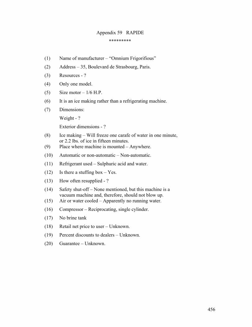
456
Appendix 59 RAPIDE
*********
(1) Name of manufacturer – “Omnium Frigorifious”
(2) Address – 35, Boulevard de Strasbourg, Paris.
(3) Resources - ?
(4) Only one model.
(5) Size motor – 1/6 H.P.
(6) It is an ice making rather than a refrigerating machine.
(7) Dimensions:
Weight - ?
Exterior dimensions - ?
(8) Ice making – Will freeze one carafe of water in one minute, or 2.2 lbs. of ice in fifteen minutes.
(9) Place where machine is mounted – Anywhere.
(10) Automatic or non-automatic – Non-automatic.
(11) Refrigerant used – Sulphuric acid and water.
(12) Is there a stuffing box – Yes.
(13) How often resupplied - ?
(14) Safety shut-off – None mentioned, but this machine is a vacuum machine and, therefore, should not blow up.
(15) Air or water cooled – Apparently no running water.
(16) Compressor – Reciprocating, single cylinder.
(17) No brine tank
(18) Retail net price to user – Unknown.
(19) Percent discounts to dealers – Unknown.
(20) Guarantee – Unknown.

457
#2 – Rapide Remarks: This machine is advertised to make ice in one minute in a carafe of water. It is driven either by hand or with a 1/8 H.P. motor. It employs commercial sulphuric acid. These sulphuric acid machines are described in detail on pages 47 through 51 of, “The Mechanical Pro- duction of Cold”, by Ewing. Apparently the machine was
invented in 1810 by Professor Leslie. This particular Rapide machine is manufactured in Paris. It can be seen in the picture that the machine has considerable glassware in it and there might be danger of breakage, allowing the sulphuric acid to get out.

458
Appendix 60 REFRIGO
********
(1) Name of manufacturer – Refrigo Corporation.
(2) Address – Milwaukee, Wisconsin.
(3) Resources – Paid in capital, $212,000.00.
(4) Size motor – ¼ H.P.
(5) Dimensions:
Maximum weight – 150 lbs.
Exterior dimensions – 11” wide x 19” long x 18” high.
(6) Trays – 3.
(7) No. of cubes per tray – 27.
(8) Ice making – Amply daily supply of pure ice cubes for table use.
(9) Automatic or non-automatic – Automatic.
(10) Place where machine is mounted – This machine can be placed on top of the ice box, at its side, or in the basement.
(11) Refrigerant used – Ammonia.
(12) How often resupplied – Because of the leak-proof character of Refrigo, the original charge of ammonia will remain in- tact for a period of many years.
(13) Is gas considered dangerous or not – Yes (See appendix on refrigerants.)
(14) Compressor – Special; silent, viatical piston type; all moving parts automatically lubricated; hermetically and aatomatically sealed to avoid gas and oil leaks.
(15) Brine tank used or direct expansion – Brine tank.
(16) Safety shut-off - (Text illegible) device that automatically stops machine in case of excess pressure.
(17) Retail net price to user - $365.00.
(18) Percent discounts to dealers – 30 to 40% in quantities.
459
#2 – Refrigo
(19) Guarantee – It is sold under a positive guarantee to give satisfaction.
Remarks: The following is quoted from the bulletin put out by the Refrigo Corporation: NO LEAKS “One of the most serious objections heretofore to the household use of a refrigerating machine was the escape of fumes through the driving mechanism of the compressor and the constant leakage of lubricating oil through the stuffing box. “These objections—common to all other types of refrigerating machines—are now for the first time entirely overcome. Our engineers, after the
expenditure of much time and money, have solved this problem by the invention of an ingenious and clever device known as an automatic sealer and lubricator for refrigerating compressors. “Heretofore as the pressure in the compressor increased, the leakage of gas and oil in- creased proportionally. This new device, however, is so constructed that the greater the pressure in the compressor the tighter and more leak-proof the auto- catic sealer becomes. “This feature—which represents one of the most important and far-reaching improvements made in recent years in household refrigeration—is thoroughly protected by a broad patent issued by the United States patent office April 6th, 1920. All infringements will be vigorously prosecuted.” “The Refrigo Corporation makes one size only according to our information, which sells for $260.00 installed in Milwaukee and outside of Milwaukee $360.00, plus installation.
(D. L. Boyd.)

460
Appendix 61 RUMPLER REFRIGERATIN MACHINE *****************************
(1) Name of manufacturer – Dr. Rumpler.
(2) Address – Germany
(3) Resources – Unknown.
(4) Models – Apparently there is only one model.
(5) Ice making – If desired, ice trays may be inserted to produce cubes of clear ice.
(6) Automatic or non-automatic – Non-automatic; see (13)
(7) Place where machine is mounted – The Rumpler machine is preferably mounted on top of a well insulated household or store refrigerator, a thick sheet of cork-board being used as a base-plate.
(8) Usual temperature of ice box – The temperature may be con- trolled as desired.
(9) Refrigerant used – Aqua- ammonia.
(10) How often resupplied – The solution of water and ammonia within the pressure tight machine may be used indefinitely.
(11) Cost of new refrigerant – Unknown.
(12) Is gas considered dangerous or not – See appendix on refri- gerants.
(13) Lubricant – The article on this machine says that no lubricant is used.
(14) Air or water cooled – Water,
(15) Brine tank used or direct expansion – Direct expansion.
“A direct expansion evaporator hangs down into the refrigerator, occupying the space ordinarily re- served for the center partition. Instead of the usual cubical tank seen in American equipments, which simply takes the place of an equivalent block of ice, a more effective and stronger construction is obtained by Rumpler by means of a grid of straight, vertical, seamless, drawn steel tubes with a
horizontal liquid feed header at bottom and a large horizontal suction gas header at top, under the base plates. The tubes offer a large cooling surface, take up very little space, and
461
#2 – Rumpler are more efficient for heat absorption than a brine-cooled flat tank surface.”
(16) Retail net price to user – Unknown.
(17) Does price include – Refrigerator - No Brine tank - --- Installation - - The machine is shipped fully charged, ready for water and wire connection, which is a simple matter.
(18) Average hours operated per day – One movement with a lever turns on the
electric heat for a period of one and a half to two hours, a second movement by hand stops the heat and turns on the
thin stream of cooling water. The effective refrigerating period lasts at less twenty-two hours per day. The next day the performances is repeated.
(19) Guarantee – Unknown.
(20) Service – There is said to be no appreciable wear and tear, the water tubing within the generator being of a composition metal which is acid resisting.
(21) Noise – There is no moving machinery and, therefore, no
noise or vibration.
462
Appendix 62 SANITARY **********
(1) Name of manufacture – Frankenberg Refrigerating Machinery Company (Successor to Sanitary Refrigerating Machinery Company.)
(2) Address – 245 Jackson Street, Milwaukee, Wisconsin.
(3) Resources - ? Mr. T. I. Jones in his paper, “Household
Electric Refrigeration”, which was published in October, 1922, says that there are twelve Sanitary Refrigerating
machines which have been in successful operation for at least twelve consecutive months.
(4) Models - (1) Contemplated (2) At present (3) Contemplated
(5) Size motor - ¼ H.P.
(6) Cubic contents - 9.6 cu. Ft.
(7) Trays - 2
(8) No. cubes per tray - 21
(9) Size cubes - 1-5/16” dia, x 1-1/2” high
(10) Automatic or non-automatic – Automatic.
(11) Place where machine in mounted – Under refrigerator
(12) If thermostatic control, give range of temperature - 5° F.
(13) Usual temperature of ice box – Average 39° to 44°F.
(14) Refrigerant used – SO2
(15) How often resupplied – Permanent charge.
(16) Cost of new refrigerant - 75¢.
(17) Is gas considered dangerous or not – Not as used in this machine,
(18) Is there a stuffing box – Yes.
(19) Air or water cooled – Water.
(20) Cu. Ft. water per day – 5 cu. Ft.
(21) Compressor – Reciprocating.

463
#2 - - Sanitary
(22) Brine tank used or direct expansion – Direct expansion. (23) Retail net price to user – About $550.00. (24) Percent discounts to central stations – to be determined a
little later. (25) Does price include:
Refrigerator - Yes Brine tank - Yes Installation - No
(26) Average hours operated per day – 8 hours (27) Estimated KW-hours per day – 1.8 KW-hours (28) Guarantee – Complete. (29) Service – Some time ago, the Western Electric Company bought
a Sanitary refrigerating machine. This machine had Bakelite pinions and one of them swelled. Sometimes it was too tight to start. SO2 leaked to the outside air. They had trouble with corrosion.
It took two men three days to recharge the
machine with SO2. They felt it was necessary to wash every- thing with gasoline before recharging. They also felt it was necessary to heat the whole system while pumping. (I asked Mr. V. R. Greene about this the next day and he said that It was not at all necessary to wash it with gasoline or to Heat the system.) They had no real trouble with the Bakelite gears outside of the time that one of them swelled. The type RSA motor was noisy.
Remarks: Water supply for condenser is also automati- cally controlled and guards against any undue high gas pressure. Water consumption based upon temperatures of water 69°F. and room temperature 75°F.
464
Late information shows that the Frankenberg Refrigerating Machinery Company, formerly the Sanitary Refrigerating Machinery Company of Milwaukee, are making an ice machine for household use of capacity of 250 lbs., of ice melting per day. The price of this machine is $575,00 f.o.b. Milwaukee complete. They also state that they will have a machine ready August 15th which will be a complete sulphur dioxide unit of 250 lbs. ice melting capacity complete and ready to run which can be put in any box in two hours, and can be put over or under box or in the basement. This unit is to be sent out fully charged at a cost of $300.00 f.o.b. Milwaukee. D. L. Boyd.

465
Appendix 63 S E R V E L __________
(1) Name of manufacturer – Hercules Corporation.
A recent report indicates that the National Electric Products Corporation, Chicago, is merely distributing and for the time being the manufacturing is done by the Hercules Corporation.
(2) Address – Evansville, Indiana. (3) Resources – The production of this Company in May, 1923, was
seven to eight machines a day. Mr. Dennedy, who was formerly on the engineering staff of the Kelvinator Corporation, says that they are handling their machines through the Public Utility Companies, and that all of the companies in the Hodenpyle Syndicate are going to sell their machines. This Hodenpyle Syndicate controls a large number of public utilities in Illinois, Indiana, Michigan and Iowa. The Public Service Companies will sell and service machines.
(4) Development – Unknown. (5) Model – 12 SerV-el. (6) Dimensions - Height Width Depth
Overall 74” 41” 25 ½” Food Compartment 30 3/8” 35” 16” Cooling Chamber 13 ¼” 35” 17” Machine Section 18” 37” 19”
(7) Size motor – ¼ H.P. (8) Trays – 8. (9) No. cubes per tray – 12. (10) Size cubes – 1 1/8 x 1 ½ x 1 ¾”. (11) Ice making – A total of 288 cubes or approximately 27 lbs. of
ice can easily be made in twenty-four fours.
(12) Automatic or non-automatic – Automatic. There is no thermostat, but the motor is started
and stopped by the pressure switch in the suction line. (13) Place where machine is mounted – It is mounted in the lower
compartment of a special refrigerator which they build or can

466
#2 – Servel.
be used in existing refrigerators, and installed remote from the refrigerator.
(14) Refrigerant used – Methyl chloride. (15) Is there a stuffing box – Yes.
The stuffing box is of special construction, and is really labyrinth bearing made up of a number of spring steel discs, with some bronze spacers between them.
(16) How often resupplied – The National Electric Products Corpora- tion says that the refrigerant should last for years, but is easily replaced if necessary.
(17) Cost of new refrigerant – Unknown. (18) Is gas considered dangerous or not – See appendix on refrigerants. (19) Air or water cooled – Air.
The air cooling is furnished by a fan, which is mounted on the idler pulley.
(20) Compressor – Two cylinder, single acting. (21) Brine tank used or direct expansion – Placed in the cooling
chamber of the refrigerator is a tank of substantial construction containing a solution of alcohol and water, which absolutely prevents any corrosion that may follow in the use of calcium chloride or a brine solution.
(22) Retail net price to user - $395.00. (23) Percent discounts to dealer – 15%. (24) Average hours operated per day – This machine runs one-sixth
of the time. (25) Estimated KW-hours per day – 2 KW-hours. (26) Description of insulation – The refrigerator which they build
is insulated with two inches of sheet cork, with a vitreous enamel steel lining, and steel exterior.
(27) Guarantee – Unknown. (28) Service – Mr. H. E. Crane says that it is easy to see the
Kelvinator influence in the design of this machine, but his impression is that is not so well built a machine as the Kelvinator.

467
Appendix 64 C. K. TRIPP’S MACHINE * * * * * * * * * * * * * * *
(1) Name of manufacturer – Mr. C. K. Tripp. (2) Address – Lynn, Mass. (3) Resources – Mr. Tripp has built a couple of refrigerating
machines and has orders for ten more. (4) Size motor – ¼ H.P. RSA motor, - 250 watts. (5) Automatic or non-automatic – Automatic. (6) Usual temperature of ice box – Mr. Tripp has a sylphon
thermostat with mercury contacts which is operated from the temperature of the brine tank. With this outfit, he suc- ceeded in keeping a pine-board box with nothing but an air space between at 32 degrees.
(7) Refrigerant used – Sulphur Dioxide (8) Is there a stuffing box – Yes,
The novelty of Mr. Tripp’s scheme is his method of packing between the low pressure chamber contain- ing sulphur dioxide and the atmosphere. Mr. Tripp has an
oil chamber in the lower part of the sulphur dioxide chamber and opposite this is an oil chamber, the upper surface of which is exposed to atmosphere. Between these two chambers is a wall and a packing box through which a rock shaft is passed. This shaft is made to rock by means of an ingenious mechanism which Mr. Tripp has device which transmits the circular motion of the motor (which is placed above the oil level) through the oil so as to rock the shaft mentioned. This shaft passes into the oil at the bottom of the sulphur dioxide chamber and in this oil is a walking beam carrying two con- necting rods which operate two pistons, thus actuating a two cylinder compressor which could be of any usual type. There is a flange on the sulphur dioxide side of the rock shaft which is pressed up against a babbit face by means of a spring, thus helping to make the joint between sulphur dioxide and atmosphere. If ever a high pressure comes in the sulphur dioxide chamber, this pressure forces the flange against the face all the harder and effectively prevents any leak.
He has an oil (Text illegible) the stuffing box. (9) Is gas considered dangerous or not – See appendix on refri-
gerants.
468
#2-C. E. Tripp’s Machine
(10) Air or water cooled – Air.
(11) Compressor – Reciprocating two cylinder, single acting.
(12) Brine tank used or direct expansion – Brine tank. Mr. Tripp feels that the brine tank is neces-
sary because small motors are inefficient and he feels there is more efficiency in running a large motor part of the time.
(13) Retail net price to user - $125.00. Mr. Tripp feels that his machine can be built
in quantities for a factory cost of about $60.00.
(14) Average hours operated per day – The motor ran one hour on and one hour off.
(15) Guarantee – Unknown.
(16) Service – Mr. Tripp found that it was necessary to pean castings of his cylinders in order to keep them from leaking.

469
Appendix 65 UNIVERSAL ICE MACHINE CO.
* * * * * * * * * * * * * * * * * * *
(1) Name of manufacturer – Universal Ice Machine Company.
(2) Address – 6915 Fort Street, East Detroit, Michigan.
(3) Resources – This company states that they have had test machines in operating for two or three years and while heretofore they have been making machines one at a time, they have their first twenty-five coming through this month and have a plant and facilities for doubling each month until they meet sales required.
(4) Refrigerant used – Ammonia.
(5) Is gas considered dangerous or not – See appendix on refri- gerants.
(6) Air or water cooled – Water.
(7) Compressor – It has a single cylinder, single acting, 250 RPM Compressor, a proximately 2” by 3”.
(8) Retail net price to user - $ 350.00
(9) Percent discounts to dealers – They state that they intend to establish sales and service agents in exclusive territory.
(10) Guarantee – Unknown.
(11) Remarks: The machine might be good for butcher shops,
but does not look very promising as a domestic outfit.

470
Appendix 66 UTILITY * * * * * *
(1) Name of manufacturer – Utility Compressor Company.
(2) Address – Adrian, Michigan.
(3) Resources – There is outstanding at the present time $300,000.00 common stock, per value $10.00. The proceeds from this stock have been used in the development of the outfit. Approximately $50,000.00 of this common stock re- mains in the treasury unsold. They are now offering $250,000.00 accumulative preferred at per value $10.00 per share. One share of no per value common is given as a bonus with each share of preferred. The preferred draws 8% interest payable semi-annually, on the first day of July and the first day of January of each year. Not less than 20% of the net earnings shall be set aside as a sinking fund each year for paying interest on preferred, and to begin retiring preferred each year after the fifth year at $11.00 per share until 1939, when it is all re- tirable. The preferred interest must be paid before dividends can be paid on the common or no per common. In case of liquidation, the preferred stockholder must be paid in full with all accumulated interest before common or no par can participate. Preferred does not vote unless interest is defaulted for one year. It then votes until interest arrears have been paid. The common and no par common votes and participates equally in all the earnings, assets and dividends after preferred interest has been paid. Mr. H. E. Crane, of the Fort Wayne Office, understands that at present the company is simply trying to sell such machines as they have in stock, and are servicing all machines sold. No further manufacturing is to be done until they can refinance. Mr. A. W. Henshaw says that their authorized now capital is $600,000.00, but they are understood to be heavily in debt.
(4) Models - (1) (2) (3) They make one size mechanical unit which is interchangeable. They make three boxes with different finish only, otherwise exactly alike. Natural wood finish,
white enamel finish, white porcelain finish. 69 ½” high. 37 5/8” wide, 22 5/8” inches deep.
(4) Size motor – ¼ h.p. The motor, which is a Holzer-Cabot ¼ h.p:

471
#2 – Utility 1725 RPM, 60 cycle, single phase motor, with shading coils, is mounted in the gas chamber. The Holzer-Cabot company furnishes the rotor and stator only. The stators are fur- nished wound in the white without treatment. They are then
given one dip and one bake of bakelite varnish. They claim to have had no trouble with this treatment. If this state- ment is true I am satisfied, from our experience, that it is because they had not had a sufficient number of machines developed. (H. E. Crane - - Fort Wayne)
(6) Cubic contents – 9.2 cu. Ft
(7) Trays – With each outfit, 12 Pyrex glass, sanitary re- ceptables, round, 1 ¾ in. diameter x 1 ¼ in. deep, sides slightly tapered.
(8) No. cubes per tray –
(9) Automatic or non-automatic – Automatic.
(10) If thermostatic control, give range of temperature - 5° F.
(11) Usual temperature of ice box – Can be set anywhere – we advise 50°, 45° low.
(12) Place where machine is mounted – In top of refrigerator.
(13) Refrigerant used – SO2 The machine was originally designed for the
use of ethyl chloride with glycerine as a lubricant, but recently they have changed to sulphur dioxide.
(14) How often resupplied – Never.
(15) Is gas considered dangerous or not – Not.
(16) Is there a stuffing box – No.
(17) Air or water cooled – Air.
(18) Cu. Ft. water per day – None.
(19) Compressor – Reciprocating two cylinder, 2 in. bore, 1 ¼ in. stroke.
(20) Brine tank used or direct expansion – Direct expansion.
(21) Retail net price to user - $400.00 $425.00 $500.00
This is according to the finish of the box.
See number 4.

472
#3 – Utility
(22) Does price include: Refrigerator - Yes-complete Brine tank - No brine tank used Installation - No installation except convenient
opening. (23) Percent discounts to central stations – 45%. (24) Average hours operated per day – with a room temperature of
70 degrees, this machine operates about 6 hours. (25) Estimated KW-hours per day – room temperature of 70 degrees,
2.1 KW-hours. (26) Guarantee – One year. (27) Description of insulation – The refrigerator is one built
especially for this outfit, and is insulated with two inches of cork board.
(28) Service – The following is copied from the bulletin put out by the Utility Compressor Company: “There is no charging with chemicals or mechanical work of any kind to be done in the home. Delivery is made in two places; first, the mechanical unit; second, one of the refrigerators, the upper portion of which is arranged to accept the unit. Two of our men simply lift and insert the unit into place, connect the cord to the socket; and everything is ready for use. It takes about ten or fifteen minutes to make the installation. Every unit is exactly alike and interchangeable. The same unit fits into any one of the refrigerator bodies. “our service stations can remove the mechanical unit and replace with another in fifteen minutes, therefore no household need be deprived of its refrigeration nor to have mechanics working in the home making repairs.”
473
GENERAL ELECTRIC COMPANY GENERAL OFFICE-SCHENECTADY, N. Y.
CENTRAL STATION DEPARTMENT 1 River Road, SCHENECTADY, N.Y.
August 28, 1924 Household Utilities Corp., 16 Hendrie Ave., Detroit, Mich. Gentlemen:
Kindly furnish me with prices, specifications and
other data covering your Electric Household Refrigerator.
This information is for my own personal use.
Yours very truly,
F. E. Dunham
(ed note: hand written in script: ‘Returned’)

474
Information from Mr. T. I. Jones’ paper on “Household Electric Refrigeration”, published in October, 1922.
Appendix 67 FRED. W. WOLF
* * * * * * * * * *
(1) Name of manufacturer – Fred W. Wolf Company.
(2) Address –
(3) Models - (1) (2) Install on any unit built type of box in
independent unit.
(4) Size motor – ¼ H.P. – 250 watts.
(5) Cubic contents – Equal to the melting of ten pounds of ice per hour.
(6) Trays – Compartments 3-7 each for two trays.
(7) No. cubes per tray – each 16- 2 x 2 in. cubes, or 10 lbs. Chunks.
(8) Size cubes –
(9) Automatic or non-automatic – Both.
(10) If thermostatic control, give range of temperature – ½ degree in food compartments.
(11) Usual temperature of ice box – 32 to 34 degrees.
(12) Refrigerant used – Wolf refrigerant.
(13) How often resupplied – Never.
(14) Cost of new refrigerant – None.
(15) Is gas considered dangerous or not – Absolutely safe.
(16) Air or water cooled – Air cooled, of course.
(17) Cu. Ft. water per day – None. None.
(18) Compressor - Reciprocating Reciprocating
(19) Brine tank used or direct expansion – Direct expansion.
(20) Retail net price - $250.00 $350.00
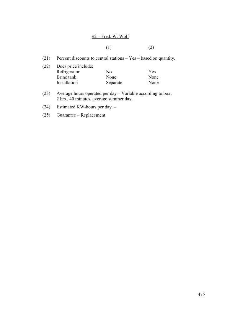
475
#2 – Fred. W. Wolf
(1) (2)
(21) Percent discounts to central stations – Yes – based on quantity.
(22) Does price include: Refrigerator No Yes Brine tank None None Installation Separate None
(23) Average hours operated per day – Variable according to box;
2 hrs., 40 minutes, average summer day.
(24) Estimated KW-hours per day. –
(25) Guarantee – Replacement.
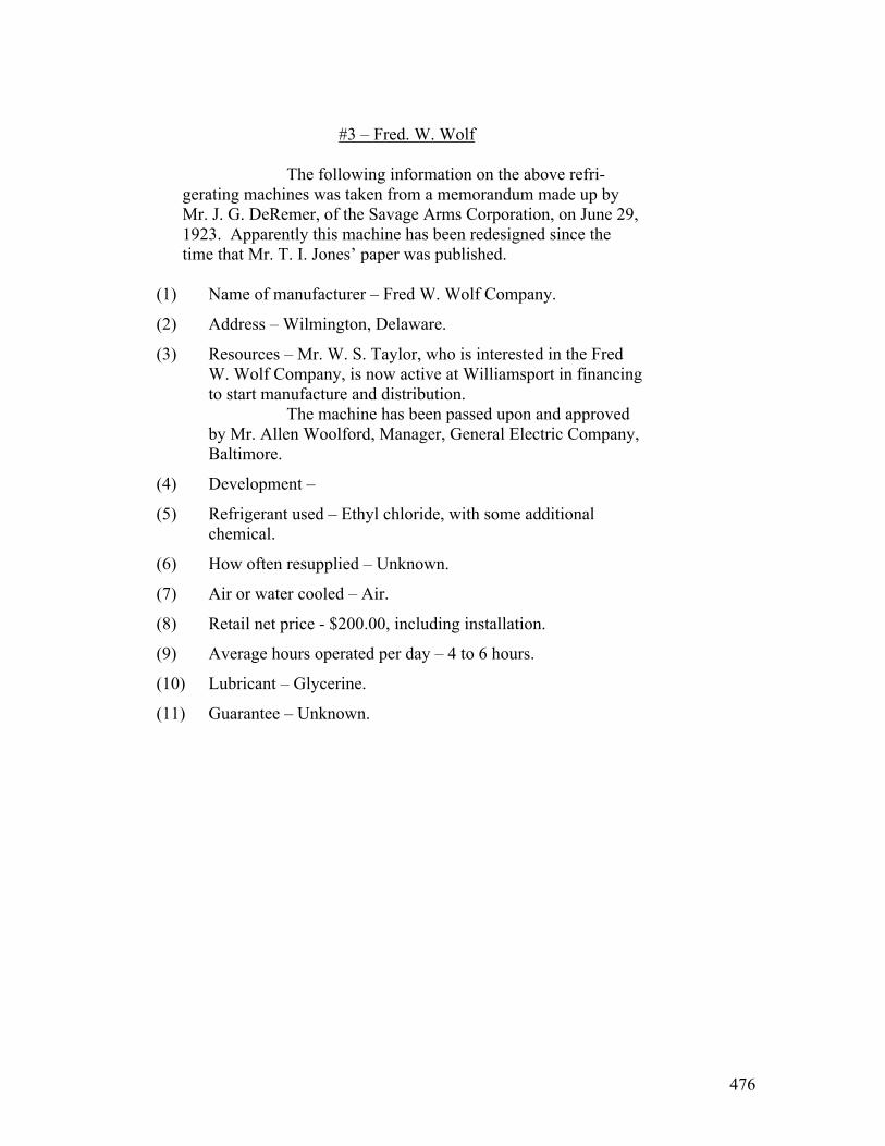
476
#3 – Fred. W. Wolf
The following information on the above refri- gerating machines was taken from a memorandum made up by Mr. J. G. DeRemer, of the Savage Arms Corporation, on June 29,
1923. Apparently this machine has been redesigned since the time that Mr. T. I. Jones’ paper was published.
(1) Name of manufacturer – Fred W. Wolf Company.
(2) Address – Wilmington, Delaware.
(3) Resources – Mr. W. S. Taylor, who is interested in the Fred W. Wolf Company, is now active at Williamsport in financing to start manufacture and distribution. The machine has been passed upon and approved by Mr. Allen Woolford, Manager, General Electric Company, Baltimore.
(4) Development –
(5) Refrigerant used – Ethyl chloride, with some additional chemical.
(6) How often resupplied – Unknown.
(7) Air or water cooled – Air.
(8) Retail net price - $200.00, including installation.
(9) Average hours operated per day – 4 to 6 hours.
(10) Lubricant – Glycerine.
(11) Guarantee – Unknown.

477
Appendix 68 WILLIAMS ELECTRICAL REFRIGERATOR – and – SIMPLEX
These two companies are apparently operated
by the same man and so far can be seen make exactly the same type of machine, in spite of the fact that there were
two separate capitalizations.
(1) Name of manufacturer – Simplex Refrigerating Corporation. Address – 40 Flatbrush Avenue, Extension, Brooklyn, N. Y.
(2) Name of manufacturer – The Electrical Refrigerating Co., Inc. Address – Woolworth Building, New York City.
(3) Resources – Simplex Refrigerating Company: Except for the statement that they are not now doing much business, this company refused to give any financial information since 1915, when they gave their assets as $371,000., including patents at $268,000.
Description of Simplex: (4) Models - (1) (2) (5) Size motor - 1/3 H.P. ¼ H.P. is amply large, however the larger frame is employed to insure against possibility of motor troubles. (6) Outside dimensions of refrigerator:
44” x 25” x 60” 48” x 25” x 60” Machine located on top of refrigerator adds eleven inches to height.
(7) Cubic contents -
- - Net storage 7 ½ cu. Ft. 8 ½ cu. Ft.
(8) Trays 8 9
(9) No. cubes per tray 12 12

478
#2- Williams.
(1) (2) (10) Size cubes - 2” 2” (11) Auto. or non-auto. Automatic Automatic (12) If thermostatic control, give range of temp. 2°F. 2°F. (13) Usual temp. of ice box 42°F. 42°F. (14) Refrigerant used - Ethyl chloride Ethyl chloride (15) How often resupplied- Lasts indefinately (16) Cost of new refrigerant - $2.25 $2.25 (17) Is gas considered dangerous or not – See appendix on refrigerants. (18) Air or water cooled - Air Air (19) Compressor - Rotary Rotary (20) Brine tank used or direct expansion – Brine tank. (21) Retail net price - $550.00 $650.00 (22) Percent discounts to central stations - . None at present None at present (23) Does price include: Refrigerator Yes Yes Brine tank Yes Yes Installation No No (24) Avg. hours oper- ated per day 8 9-10 (25) Est. KW-hr. per day 2 ½ 2 ¾ - 3 (26) Guarantee 3 years 3 years (27) How many automatic machines have you now in use that have been in successful operation for at least twelve consecutive months – 12. The above information was taken from Mr. T. I.
Jones’ paper, “Household Electric Refrigeration”, presented at the forty-first convention of the Association of Edison Illuminating Companies held at the Greenbrier, White Sulphur Springs, West Virginia, October, 1922.

479
#3 – Williams. On May 23, 1923, Mr. Stevenson visited Mr. E. T. Williams, of the Simplex Refrigerating Corporation, Sperry Building, Manhattan Bridge Plaza, Brooklyn, N.Y., telephone 5408 Main. He is designing a new refrigerating machine which will have 7 ½ cu. Ft. food capacity and will sell complete for $350.00. He has a vane type rotary com- pressor with a ground and lapped steel joint for a stuffing box. He uses ethyl chloride. The lubricant is glycerine with powered graphite. Some glycerine oozes out through his lapped steel joint, and where it reaches the air causes
corrosion. He is working on a new arrangement where the motor will drive a set of permanent magnets arranged in the
form of a sphere. There will be a diaphragm 1/20,000 inch thick in the form of a spherical surface and inside of this will be a twenty pole laminated rotor. Personally, Mr. Stevenson thinks this diaphragm will heat in the same way that the diaphragm of the Autofrigor machine heats. Mr. Williams has had twenty machines out for two years and has had to replace his stuffing box every year on account of the corrosion, due to the glycerine. He has also had some trouble with cracking of pipe joints. The rotary vane compressor is made with a clearance of ½ thousandth of an inch. He says he can build the rotor of this compressor for $15.00. The vanes are held out both by pressure and centrifugal force. Mr. Williams has spend about $250,000.00 so far, and when he completes his development next year, would be very glad to turn it over to someone if a satisfactory financial arrangement could be reached.

480
Appendix 69 REPORT OF REFRIGERATING MACHINE DEVELOPMENT AT FORT WAYNE WORKS _ _ _ _ EARLY EXPERIMENTS In 1911 the General Electric Company undertook
the manufacture, for the Audiffren Refrigerating Machine
Company, of A-S machines in four sizes: two ton, one ton,
one-half ton, and one-fifth ton.
Through our direct connection with the manufacture
of these machines, and indirect connection with their
commercial exploitation, we were impressed with the desirability
of having a smaller unit, suitable for domestic use, of 175
to 200 pound capacity. That is, one which will produce refrig-
eration equivalent to the melting of 175 to 200 pounds of ice
per twenty-four hours. Naturally we first considered the develop-
ment of a smaller Audiffren machine. An investigation of this
problem, however, convinced us that it was not desirable,
for several reasons:
1st: This type of construction, entailing the
use of open brine and water tanks in which the machine
revolves, and the cooling by circulation of brine, does not
lend itself to domestic installation on account of the space
required, moisture and dirt, inefficiency of outfit in small
sizes, and expense of installation and operation.

481
2nd: The labor cost of construction of a 200
pound machine would be about the same as the 400 pound size,
and we would save only a small amount of material.
It was then decided to investigate the many small
machines that were being exploited or under development,
hoping to find something suitable for the purpose which
we could acquire. We purchased and tested several outfits,
and inspected many. All had faults or shortcomings as
gauged by the standards set up as a result of our six or
seven years experience with the Audiffren machine and our
study of the domestic and refrigerating problem.
It was then decided we would try to develop a
machine which would embody our ideas of the necessary
qualifications of a domestic refrigerating machine.
There was a wide spread feeling that a
refrigerating machine for domestic use should be built to sell
to the ultimate user at $100 to $150, and at this price the
market would be so large that they could be manufactured
on a Ford basis.
The Audiffren machine is hermetically sealed and
has no packed glands. In this respect it has been generally
conceded superior to any other refrigerating machine. It
was, therefore, with reluctance and some misgiving that we
considered a design in which the power would be applied
through a stuffing box. However, the seemingly unsurmountable
2.

482
difficulties of building a motor that would withstand the
atmosphere of gas and oil, and function properly without
attention for years; of getting the current into the motor
through conductors with insulation that would be gas and oil
tight and still keep the cost within the limits set; together
with the fact that all the small refrigerating machines on
the market or under development were of the stuffing box
type, prompted us to attempt a design in which a stuffing
box was employed.
In the Spring of 1917 we made drawings and a
working model of an OC-2, Form B machine, using one vertical
doubt-acting oscillating cylinder, actuated by an eccentric
on a horizontal shaft, one end of which was supported by a
blind bearing, the other end passing through a stuffing box
in the case and carrying a fly-wheel pulley for belt drive.
(See Plates No. 1, 2 & 3.) Ed note: plates too dark to photocopy however the original GE photos are #’s
142039, 142038, 142062 and are in the GE photo collection at the Schenectady Museum.
The cylinder was submerged in oil, and the compressed
gas was carried by a pipe to two closed sheet metal pans
arranged with suitable baffles, and connected to an enclosed
sump, in which was a float type expansion valve, the condensing
pans and float valve being submerged in cooling water flowing
through a cast-iron condensing chamber. From the expansion
valve the condensed gas was piped into a tank of brine in the ice
compartment of the refrigerator. From the evaporator a pipe con-
ducted the expanded gas back to the suction side of the compressor.
3.

483
Cast iron base carried the compressor, condenser, and
belted motor.
The control equipment consisted of the following:
A water valve operated by direct pressure in a
sylphon bellows connected to the compressor.
A gas thermostat consisting of a sylphon to which was
attached a tube partially filled with liquid SO-2, and a
contact lever. The change in pressure, due to boiling and
condensing of the gas, actuated the sylphon bellows, which
moved the contact lever between two contact points.
A single coil contactor, CR-2820-1018.
Fuse block and fuses, and a tumbler switch.
The tests on this working model showed it to have
a good refrigerating capacity, and the outfit looked promising
enough to warrant the building of some additional machines,
which could be tried out in actual domestic service. Seven
(7) machines were built, three being installed in homes of
employees of the company in Fort Wayne, two in the Works
Cafeteria, and the balance in the Testing Room.
One of these outfits operated successfully for a
year and three months; one for eleven months, and the balance
failed in from two weeks to six months. Trouble soon developed
in the sheet metal pans used for condensing and evaporating
pipe for condenser and evaporator. The principal source of
trouble, however, was the stuffing box.
4.

484
The experience gained through the operation of these
seven machines, coupled with our observations of the troubles
other manufacturers were having with stuffing boxes, has
convinced us that a successful domestic refrigerating machine
must be one in which the machine and motive power are enclosed
in a gas tight case. We realized that this type of con-
struction meant and increase in the cost, with a corresponding
reduction in the extent of the market.
In the various attempt at developing a domestic
refrigerating machine, practically every type of compressor
has been tried. In selecting the oscillating cylinder type
of reciprocating compressor, we are not making an experiment.
Abbe Audiffren, in the development of the A-S machine,
used at different stages most of the types of compressors that
are being tried by various manufacturers at the present
time, only to discard all of them for the oscillating cylinder
type, which has been used in the Audiffren machine for
twenty-five years.
In September 1919 an appropriation was approved to
make drawings, patterns, tools and build one model of a
400-lb. domestic refrigerating machine with totally included
motor.
This size was selected, as it would permit of the
use of standard Audiffren #2 cylinders, snifter spring valves
piston, piston rods and straps, eccentric, and float type
expansion valve.
5.
485
The Schenectady Research Laboratory developed
some metal glass leads, giving us a gas and oil tight means
of getting the current through the enclosed case.
The use of a motor sealed up in an atmosphere of SO-2
gas and oil was the only radial departure from common practice
or our practice in the A-S machine.
Various types of motors were considered for the
purpose and, after weighing the advantages and disadvantages
possessed by each, it was decided that a split phase motor,
having a wire wound stator and a squirrel cage rotor, offered
the fewest complications. The restrictions of the N.E.L.A.
in regard to starting current allowable did not give us a very
wide leeway on starting torque, but it seemed sufficient.
The construction adopted is shown by Plate #4. Ed note: plate too dark to photocopy however the
original GE photo is #’ 142303 and is in the GE photo collection at the Schenectady Museum. The tests made on this machine were very
encouraging, and three additional machines of this size were
built, tested, and put in service. The designation of
this size is Type OC-3, Form E.
TYPE OC-2, FORM E DEVELOPMENT
Satisfied that this type of construction was
practical, we then designed a 200 # machine, type OC-2, Form E,
suitable for domestic, use, and built five (5) models. (See
Plate #4.)
In the first machine of this type we used motors
having the standard insulation treatment. These motors
functioned properly, but after several months of operation
6.

486
we opened one of the machines for examination, and found
the compound had flaked off. Then followed a long list of
experiments with various treatments, from which it was found
that a motor having the least amount of treating compound
necessary to hold wires in position gives the minimum
amount of trouble. During all of these experiments, no motor
failed, due to lack of insulation. The troubles were all due
to compound coming off the wire and interfering with the
operation of the compressor by gumming the bearings or
clogging the expansion valve.
In the use of the split phase motor, means must
be provided to cut in and out the starting winding.
In this application, the motor being sealed up
in the gas tight case, it is very important that we employ
the minimum number of moving parts and keep out of the
case any parts that are subject to wear or liable to get
out of order. Our Experimental Laboratory developed an
external device providing a means for cutting in and out
the starting winding and also protecting the motor against
excessive current. (See Plate #5.) Ed note: plate too dark to photocopy however the original GE photo is
# 142202 and is in the GE photo collection at the Schenectady Museum.
For the automatic control of temperature, we used
the Type SL gas thermostat. (See plate #6, Fig. 1) (Ed note: GE photo# 142306) which in
conjunction with the starting relay designed by the text illegible
and stopping of the motor.
7.

487
For the automatic control of the cooling water we
designed a water control valve to operate as a function
of the temperature of the water in the water jacket of the
machine. (See Fig. 1, Plate #7) Ed note: GE photo# 142304
This consists of a sylphon in a cast brass case
located outside the casing. From the bottom of the sylphon
a copper tube, sealed at the free end, extends into the water
liquid, preferably Ethyl-choride, which due to changes
in the temperature of the water in the water jacket caused
the sylphon to expand or contract, and this motion was
transmitted to one end of the valve stem of an ordinary
Lunkenheimer whistle valve by means of a pin, causing the
valve to open when the cooling water reached a predetermined
temperature; the valve was closed by the pressure of a
phosphor bronze helical spring on the other end of the
valve stem.
The top bearing of the motor shaft is lubricated
by oil forced through the hollow shaft by a centrifugal
pump located at the lower end of the shaft which is
submerged in the oil in the compressor case. On the motor
shaft is mounted a machine steel pinion in mesh with a
fabrooil gear on the eccentric shaft through which the speed
is reduced from 1725 RPM to 493 RPM.
Two (illegible text) oscillating
cylinders actuated by piston rods, eccentric straps, and
eccentric are submerged in oil.
8.

488
The condensing chamber is located below the
compressor chamber with which it is in communication by
means of two stand pipes opening near the top of the
compressor chamber well above the oil level. In the
condensing chamber is a coil of copper pipe through which
the cooling water passes from the hollow base. This pipe
is extended through the compression chamber to the water
jacketing space surrounding the motor housing.
In the bottom of the condensing chamber is a
sump for the collection of the condensed gas, and in this
sump is located the float type expansion valve. The machine
is mounted on an insulated lid which closes the opening
in the top of the cooling compartment of the refrigerator.
From the lower side of this lid is suspended the lid of the
brine tank, which supports the evaporator, consisting of two
coils of copper tugging connected to the bottom of a brass
cylinder closed at both ends which constitutes the oil
separator. From the expansion valve a small copper tube
conducts the liquid SO-2 into the top of the oil separator.
From the middle of the oil separator, a larger copper tube
passes through the top of the oil separator and extends up
to the top of the condensing chamber where it enters the
illegible text to the suction ports of the
cylinders.
The brine tank enclosing the expansion coils
is fastened by screws to its lid. At the bottom of the
9.

489
brine tank is an insulated freezing compartment containing
two pans in which about four pounds of ice can be frozen
for table use.
This was the condition of the development at the
end of 1920. The five OC-2 machines of this model had been
put through numerous factory tests with satisfactory results,
but the real test for a device of this character is
operation in actual service under the conditions obtaining
in different households in different sections.
In January, 1921, it was decided to make this
trial, and that for convincing results about twenty-five
(25) installations should be made.
It was originally intended to sell a few machines
but just about the time we were ready a U.S.
Patent, No. 1362757, was issued to Douglas Henry Stokes of
Cremorne, near Sydney, Australia, and our Patent Dept.
withdrew their approval of our design. Later patent
approval was again given on our design. As we had our
machines ready, and summer was approaching, we decided to
place the machines in service, on a consignment basis,
with our own people at Schenectady and Fort Wayne, so
that we might have practical experience from these machines
under varying conditions of operation.
The difficulty of finding a number of
Illegible text out in their refrigerators
for an experiment of this kind, coupled with the fact that the
majority of ice cooled refrigerators are not suitably
10.
490
insulated for mechanical refrigeration, made it necessary
to purchase refrigerators for the purpose. Accordingly,
after an investigation of many of the lending makes of refriger-
ators, and consulting with the manufacturers regarding the
construction and size desirable, we ordered from the Jewett
Refrigerator Company of Buffalo, a design embodying the
arrangement and features we felt best suited for this
purpose. (See Plate #23.) (Ed. Note GE photo# 142219) The outfits were built, and early
in the Spring of 1921 installations were made. Mr. E. G.
Waters arranged for the placing of ten (10) outfits at
Schenectady, and Mr. Hunting assigned the balance.
All of these outfits are charged to the individuals
on consignment, Mr. H. J. Riffel, Industrial Control Engr.
Dept., was assigned to install and service the machines at
Schenectady. The balance of the machines were taken care of
by the Refrigerating Dept. of Fort Wayne.
With each machine at Schenectady and Fort Wayne
was installed a special M-2 Demand Motor, arranged to record
the number and duration of the operating and idle periods.
Charts were changed once each week, at which time readings
were taken of temperatures in the refrigerator, and daily
records of air temperatures at Schenectady and Fort Wayne Illegible text
All of these outfits replaced the existing
means of refrigeration, and it was, therefore, important
that continuity of service be maintained, and observations
11.

491
and changes be made with the least possible annoyance to the
users.
During this trial period, whenever a machine failed
or developed a fault in any part, it was brought back to the
factory, carefully examined, repaired, and the design of
the part modified if required.
The changes made in the various parts of the
machine, based on our experience, were neither fundamental
nor serious and were, as will be seen from the following
paragraphs, accessory details which were easily corrected.
The fact that some machines are still operating satis-
factorily with parts which have proven defective in other
machines shows clearly the necessity for having experience
from quite a number of machines before deciding on a design
for commercial exploitation. As an illustration: The
Fabroil gears proved defective, and yet several machines
are still operating with such gears. If we had put out but
two or three machines we might bad been deceived about the
Fabroil gears if they had been the few that have so far
continued to give service.
MODIFICATIONS
MOTOR: The construction of the motor is the same at this
time as when these trial machines were built, the troubles
with treating compounds having been encountered and worked
out in the first models, and a treatment of one dip and one
bake of G. E. #450 Varnish adopted as standard.
12.
492
METAL GLASS LEADS: The metal glass leads, as developed
by the Research Laboratory at Schenectady, consisted of a
conductor placed in a glass tube with thick wall and a bore
slightly larger than the diameter of the conductor. The glass
tube was inserted in steel tubing, the inside diameter of
which is slightly greater than the outside diameter of the
glass tube. It was then heated in a hydrogen furnace and swaged
down, a portion being left the proper diameter on which to out
a 3/8” pipe thread. In the leads furnished for these trial
machines the distance between the outer sheath and the
conductor was very small, especially at the end inside the
machine and considerable trouble was experienced with leads
becoming grounded at this point. The leads were then changed,
leaving the inside end the same diameter as the threaded
portion, which gives sufficient insulation. Since this
change we have had no trouble. (See Plate #16) (GE photo # 142299)
GEARS: In the experimental machines we first used spiral
metal gears. These were too noisy and the next attempt
was a Micarta pinion and cast iron spiral gear. This
combination failed, as the Micarta would not stand up in the
oil and gas. We next tried a machine steel pinion with a
spiral fabroil gear and as this combination was satisfactory
so far as noise was concerned, it was used in the trial
machines. After a few weeks of operation several of the
machines became noisy and (illegible text) the teeth of the
gears were stripped, and an investigation of these failures
convinced us that fabroil gears would not be satisfactory
13.
493
for this purpose and a change was made to machine steel,
herring bone pinion and Alquist type cast iron herring bone
gear, which is the standard at this time.
CYLINDERS, PISTONS, PISTON RODS,
ECCENTRIC STRAPS & ECCENTRIC: In the OC machine we use
the same type of oscillating double acting cylinders, pistons,
piston rods, eccentric straps and eccentric as has been used in
the A-S machines for years, mounting these in a horizontal
plane, which is preferable to the vertical plans mounting made
necessary by the construction of the A-S machine. Only one
change has been made in these parts since the original model.
In the A-S cylinder the piston rod passes though a gland in
The yoke end head which construction requires very close
fitting piston. (See Fig. 1 Plate 12) (GE photo # 142301) We found that when
the machine was stopped in certain conditions of temperature
we did not have sufficient starting torque in the motor to
start it. We then extended the piston rod through the head
end of the cylinder giving the piston rod a bearing in both
yoke and head end of cylinder. (See Fig. 2, Plate 12) This
permits of an easier fit between the piston and the cylinder
wall, reduces to a minimum the possibilities of wear at the
point where the piston rod passes through the yoke end of
cylinder, and keeps the piston in perfect alignment. This
change has entirely overcome the tendency to stall the motor
and enables it to start the machine under and conditions
of temperature with terminal voltage as low as 60 volts.
14.

494
FLOAT VALVE: The float type expansion used is the A-3
machine was adopted for the OC machines with a slight
modification. The shape of the valve seat was changed to
minimize the chance of foreign matter lodging in the opening
and the plunger rod was provided with a steel pilot to keep the
opening clear. These changes have since been standardized for
the A-S machines.
EQUALIZING VALVE: In our first machines we made no provision
for equalizing the differences in pressure between the
condenser and the evaporator when the machine was stopped.
The only way these pressures could equalize was by leakage
past the valves and considerable times was necessary to accomplish
this. The result was that the motor would stall if an attempt
was made to start the machine shortly after it was stopped.
This as a condition apt to arise due to temporary interruption
of the current.
None of the small refrigerating machines on the
market have an equalizing device, but we felt such a device
was desirable and we developed a centrifugally operated
equalizing valve(See Plate # 15) (GE photo # 142308) similar to the equalizing
valve used in the A-S machine.
This consists of a means for opening a passage
from the condenser to the evaporator just before the
machine stops, thereby equalizing the pressures and reducing
the starting torque required of the motor. This was
incorporated in all of the later machines.
15.

495
EVAPORATOR BRINE TANK
AND COOLING MEDIUM: The evaporator and brine tank used in
these trial machines is shown on Plate #8.
No change has been made or found to be desirable
in the evaporator.
The brine tanks were made of sheet copper which
was found unsatisfactory, due to the odor produced by the
oxidation of the copper. The advantage of the cylindrical
shape, as far as case in cleaning is concerned, is offset
by the disadvantage of its having smaller cooling surface
than a rectangular tank adaptable for the same size cooling
compartment of a refrigerator. The freezing compartment for
making table ice was attached to the bottom of the brine tank,
but we found the time required for freezing by this method was
excessive, due to the fact that the only cooling surface
available was the top of the compartment. On account of
these objections we made the later brine tanks of sheet steel
rectangular in shape, with an opening in the front in which
we welded a freezing compartment so that it is surrounded
by brine on all sides except the front. The size of the
freezing compartment has been increased so that 8 pounds of
ice can be frozen, whereas only four pounds could be made
in the original compartment. (See Plate #9) (GE photo# 142309) For installations
where a larger quantity of ice is required, we are developing
an outfit to cool a refrigerator, and at the same time freeze illegible text
16.

496
The sheet steel tanks where painted, but we have had
some trouble with the surface rusting, which we think can be
overcome by covering the tank with a vitreous enamel. This
we are trying out at the present time. Various cooling
mediums have been tried but brine made from common salt (Sodium
chloride) seems to be the most satisfactory. Calcium chloride
has no advantages over sodium chloride for the temperatures
at which we work, and is more expensive, harder to mix, ad must
be very carefully handled. A glycerine and water
solution was tried out but we found that the water would
freeze out of solution. Ethylene Glycol and Carbon Tetra-
chloride were considered, but found to be too expensive.
Alchol is unsuitable because it is too volatile and its odor
is objectionable in a refrigerator.
The experience we have had with the machines
installed on these special Jewett refrigerators indicates
that the brine tanks now in these refrigerators are too
small for the best results, but the size of the tank was limited
by the size of the cooling compartment in the refrigerator.
Experience indicates that for best results a refrigerator
should have a cooling compartment the volume of which is
25% to 35% of the total volume of the refrigerator. This is
a matter to be taken care of when applying our machines to
any given refrigerator.
LUBRICANT: The lubricant used in this machine is a mineral
oil developed by the Standard Oil Co. of Indiana, for use in
the A-S machine. It is satisfactory in all temperatures

497
17.
ordinarily encountered in this class of work, but it is
not altogether satisfactory for temperatures below 6°F.
Our experience with the A-S machine indicates that
an animal or a vegetable oil is not suitable for use in a
sulphur dioxide refrigerating machine, because they form
a quantity of foam, and tend to form an emulsion which
prevents the proper separation of oil and refrigerant and
otherwise interferes with the functioning of the machine.
The best oil for this work has been found to be a colorless
mineral oil. At first, a Russian colorless mineral oil was
used in the A-S machines, but after the source of supply
of this oil was cut off by the war, a colorless mineral
oil, produced in California, was substituted. Great care
in exercised to insure that the oil is free from moisture
or acid. This is refined by the Standard Oil Co., and is
known as #2470 oil. Its physical characteristics are as
follows:
Chill Point 6°F
Cold “ 4°F
Viscosity at 85°F 422 seconds Saybolt Viscometer
Viscosity at 105°F 230 “
This has been used in all OC machines, and has
proven satisfactory.
WATER CONTROL VALVE: The automatic valve for controlling
the flow of cooling water through the machine has been the
source of considerable trouble. The construction of the
design sent out on the trial machines is shown by Fig. 1,
Plate #7. (GE photo # 142304) In this the sylphon is located outside the casing.
18.

498
with the volatile liquid tube extended into the water
jacket of the machine. On account of the large part of the
pressure imposing element being outside the water jacket, the
temperatures of the water at which the valve would open and
close, were effected by the temperature of the ambient air.
To overcome this, the design show in Fig. 2, Plate #7 (GE photo # 142304) was
used, in which the sylphon with its cast brass case was put
inside the water jacket, the base of the sylphon being fixed
to the case with the top free to move responsive to pressure
of gas on the inside. The action of this design was sluggish
and we then changed to the design shown in Fig. 3, Plate #7,
in which the sylphon is enclosed in a spun copper case
attached to the top of the sylphon: the pressure pin
in this design passing into the sylphon and being fastened
to the bottom or free end. The volatile liquid was put
inside the spun copper case surrounding the sylphon so that
pressure were exerted on the outside of the sylphon instead
of on the inside as in previous designs. This was an improve-
ment over the previous attempts, but still not satisfactory.
The many transfers of heat in a design where the vavle is
operated as a function of the cooling water temperature
results in a lug in its operation, which permits undesirably
high temperature and pressure to build up in the compression
chamber. We then changed to the design shown in Fig. 4, Plate
#7. In this a smaller double ply sylphon is sealed inside the
compression chamber and operated as a function of the pressure
in the compression chamber. This has given no trouble and
19.
499
its action is very satisfactory. With the maximum travel
of 1/16” and the maximum pressures to which the sylphon will
be subjected, the manufacturers guarantee a life of two to three
million strokes, which would make it safe long beyond the
life of this machine.
THERMOSTAT: For the automatic temperature control of the
OC outfit a design of thermostat as shown in Fig. 1, Plate #6 (GE photo # 142306)
was made in which one end of which makes contacts in a relay
circuit. A small quantity of sulphur dioxide is placed in
the metal tube, the free end of which is then sealed off.
When the temperature of the tube is changed, the pressure
is the tube and sylphon is changed causing the sylphon to
expand or contract and move the lever. The adjustable
counterweight provided means for raising or lowering the
temperature and the range was adjusted by moving the contact
points.
At the time this was used we were attempting to
control the temperature, between narrow limits, in the food
compartment of the refrigerator. This we found was impractical
for the reason that improper loading of the food shelves
or obstruction of the air passages often retarded or stopped
illegible text the result the machine would run
until the brine was frozen up.
We then decided to control the brine temperature
and also to lengthen the duration and reduce the number of
20.
500
running periods of the machine. This requires a wider
range than we could get with this design, which already
required too much space, so it was changed as shown in
Fig. 2, Plate 6, (GE photo # 142306) in which a helical spring was used for
a course balance of the sylphon, the finer adjustment benig
accomplished by a counter-weight on a shortened lever.
In both the first and second design some trouble
was caused by chattering of contact due to vibration. To
overcome this we changed the design to that shown in Fig. 3,
Plate #6, in which the lever is extended beyond the
contacts and on insulated block fastened to the end.
Adjustable pins are provided so that the insulated end
of the lever touches the pin and the lever is flexed to make
the contact. This counter-weight was omitted and means pro-
vided for finer adjustment of tension of helical spring to
raise or lower the temperature.
STARTING RELAY: The starting relay used in connection with
the thermostat as one designed by the Industrial Control
Dept. at Schenectady. The single coil relay, CR-2820-1018,
was used on the experimental machines, but did not prove
reliable. This was discarded for the double coil type
CR-2820-1033-A (See Plate #10) (GE photo # 142302) which was used on the trial
machines. We have experienced no trouble from this source.
STARTING AND OVERLOAD DEVICE
FOR SPLIT PHASE MOTOR: This device, developed by the
Experimental Laboratory at Fort Wayne, had been used on all
21.

501
of the OC, Form E machines and has proven satisfactory. The
only changes made were the use of a molded base instead of
a wooden base as furnished with the first outfits and size
of contact points increased. (See Plate #6) (GE photo # 142306)
CONTROL CABINET: For the mounting and protection of the
control devices a sheet cabinet was developed. In the
first design the back and two sides were made in one piece
with the top, bottom, and front in one piece, studs extended
from the four corners of the back through the front which
was held in place by wing nuts with provision made for
scaling wires. The cabinet was mounted at the side of the
machine and supported by iron brackets from the base. The
metal glass leads from the machine extended into the cabinet
through holes in the back. (See Plate #14) (GE photo # 142111)
The cabinet contained the fuse block, tumbler
switch, thermostat, starting relay, starting and overload
device and wiring. This cabinet was not satisfactory, and
it was changed to the design shown in Plate #10 (GE photo # 142302), in which
the back and four sides are in one piece, with a removable
cover forming the front, which is held in place by two
bolts with wing nuts.
The cabinet in the present design is supported
by brackets bolted to the flange between the compressor and
condenser chambers. The back end is provided with conduit
bushings for the currents leads. The front end carries the
tumbler switch, overload react button, and a starting button.
22.

502
The starting button is provided to permit of manually starting
the machine at anytime.
PRESSURE OVERLOAD
PROTECTIVE DEVICE: Plate #11 (GE photo # 142305) shows a device for
automatically stopping the machine whenever the pressure reaches a
predetermined maximum. This consists of a small double ply
sylphon with plunger, placed in the compression chamber the
same as in the water valve, the plunger being arranged to
open the motor circuit when predetermined pressure is reached.
This device has been tried out in one machine and functions
properly, but it will not be incorporated in the machine
until something of this kind is required by legislation
or competition.
WATER INLET: The water control valve is used to regulate
the time at which water is running through the machine, so
that water will be used only when needed. In order to
control the amount of water supplied to the machine, we
employed a globe valve or a needle valve in the supply line,
adjusting those valves for the admission of the proper
amount of water. It was soon found that these valves were
a source of trouble, due to the lime, coals or sediment collect-
ing in the valve and due to the erosion of the valve points
and seats. To overcome these troubles we designed a water
inlet, as shown in Plate #13, (GE photo # unknown) which consists of a valve body on
which is placed a removable strainer and in the outlet and
of which is screwed a plug with a small orifice drilled
through it. This orifice is made of the proper size to
23.

503
permit the flow of the right amount of water according
to the temperature and pressure of the water supplied. The
high velocity of the water through this small orifice
insures its being kept free from deposits. Fixed orifices
plugs of various sizes are available for the different
conditions of water supply. These plugs are interchangeable
and easily removed. The strainers can be easily removed and
cleaned when necessary without interfering with the operation
of the machine.
SYLPHON BELLOWS: A sylphon bellow is used in the thermostat
and another one is used in the water control valve. This is
a device made by the Fulton Company, Knoxville, Tenn. It
consists of a flexible metal bellows as shown in the Plate #17. (GE photo # 142300)
Tests on these devices indicate that the average
sylphon can be subjected to over 3,000,000 complete cycles
of expansion and contraction without failure, and that the
single ply sylphon is satisfactory for use in the thermostat
where the travel does not exceed 1/32” and the gas pressure
does not exceed 60 pounds per square inch but averages about
30 pounds; while the double ply sylphon is satisfactory for
use in the water control valve where the gas pressuer does
not exceed 65 pounds and the stroke is not more than 1/16”.
These devices are widely used in temperature
and pressure control work. They (illegible text) to be reliable
and to have a long life.
APPLICATION OF MACHINE: Many small refrigerating machines
are connected to refrigerators by drilling through the wall
24.
504
or the top of the refrigerator, making the openings slightly
larger in diameter than the diameter of the connecting
pipes, which are then run through these openings. A few OC
machines were connected up in this way, one of these being
shown in plates Nos. 21 and 22, (GE photo #s 142095 and 142094) where the two small pipes
run down from the machine, through the back of the refrigerator,
into the ice compartment, and into the evaporator. This
method of connecting is objectionable in that it makes it
necessary for machine and refrigerator to be assembled
before machine is charged; and if repairs are necessary,
machine must be discharged on the job, or refrigerator must
be returned to the factory with the machine.
Another method tried out was that of mounting
the machine in a compartment in base of refrigerator, as
shown in Plate No. 3, (GE photo # 142062) where a type OC-2, Form B machine is
mounted in base of Monroe refrigerator. While this was a
somewhat neater and more easily handled outfit, it was open
to the same criticisms as the above described outfit. In
order to overcome these disadvantages, the machine was mounted
on a base which would fit into an opening about 14” x 14”
out in the top of the refrigerator; the brine tank, with
evaporator, was mounted below this base, as shown in Plate #8. (GE photo # 142307)
Connecting pipes and thermostat tube are run through this
base, making this a complete unit which can be assembled,
charged and tested in the factory, after which it can be
shipped out and set in place with base resting in opening in
25.

505
top of refrigerators. In case repairs are necessary, this
unit can be removed from the refrigerator and returned
to the factory, and another unit put in its place.
This type of unit can be used in practically
any kind of refrigerator, when an opening of the proper
size is out in the top of the refrigerator, and it can
also be used on brine tanks, drinking water tanks, etc.,
by using the base on which the machine is mounted to form
a part of the cover of the tank.
This unit construction is decidedly advantageous in
manufacturing, shipping, and servicing the outfits, but it
has the disadvantage, when applied to a refrigerator, of
requiring considerable head room about the refrigerator,
and it is further objectionable in that it sometimes causes
the noise and vibration from the machine to be amplified
because the machine is not fastened down to a solid
foundation. Our experience, however, has been that in a
majority of installations the noise and vibration are not
objectionable.
COMBINATION ICE MAKING &
REFRIGERATING PLATE: In common with most all manufacturers
of domestic machines, we made our first designs and
installations by combining the refrigerating machine with
the box. We mounted it on top of the box immediately over
the ice compartment. The purpose (illegible text)
of first cost and a minimum cost of operation, as the
refrigerating machine does not have to handle and heat except
26.

506
that which it extracts from the box, there being now brine or
gas lines that are absorbing heat. In many homes, however,
this type of installation does not meet the requirements.
The location of the refrigerator may be such that the small
amount of noise from the refrigerating machine is objectionable,
or a very considerable quantity of ice may be required in
addition to the cooling of the refrigerator itself. To meet
such conditions we have developed two types of installations
illustrated in Plates 19 and 20. (GE drawing #s K-1793000 and K-1793008)
Plate #19 illustrates the type of installation
where we mount the refrigerating machine in the basement or
some other place a little distance say from the refrigerator,
in order to eliminate the noise. In this type of installation
two small copper pipes heavily insulated connect the refriger-
ating machine with the evaporating coils in the brine tank in
the ice compartment of the refrigerators. The one line carries
the liquid SO-2 to the evaporator and in the other line
the expanded gas is carried back to the compressor in the
machines. Such an installation as this has been operating
very successfully since last July in the residence of
Mr. P. S. Hunting at Fort Wayne.
Plate #20 illustrates the type of installation to
be used where a considerable quantity of ice is required, more
that is made by the small pans in the brine tank, and where
it is desirable to locate the machine in the basement or some
other place a little remote from the refrigerator itself.
27.

507
This installation is similar to that illustrated in
Plate #19 except that in addition there are two small copper
heavily insulated lines connecting the header in the brine
tank with a coil in a brine tank in the basement, in which
are located the cans of water to be frozen. Such an installa-
tion as this has been under test in the factory for several
weeks, and while not all the tests on it are completed, it
gives every evidence of being entirely satisfactory. The
usual type of installation, where a considerable quantity of
ice is required, is to mount the refrigerating machine on
the top of the brine tank, in which the ice cans are
located, and then, by means of a pump, circulate brine
from this tank to coils in the ice compartment of the
refrigerator. (See Plate #18) (GE photo # 142310) There are some serious
objections to this type of installation. First, it costs
more to install; second, the brine pump is a device
requiring considerable maintenance; third, a most serious,
of all, it cost a good deal more to operate because it is
necessary to operate the brine pump motor continuously
and in 24 hours operation the energy required is almost
as much as is required for the intermittent operation of
the refrigerating machine which does the cooling. The
type of installation shown in Plate #20 (GE drawing # K-1793008) eliminates the
brine pump with all its noise, trouble, maintenance expense, illegible text
outfit is very little more than that required to cool the
refrigerator and to freeze the ice. Our effort in
28.

508
developing this combination ice making and refrigerating
type of installation has been to reduce fist cost by
eliminating the brine pump, and by having somewhat smaller
insulating lines to connect the machine with the box and the
freezing tank. We also eliminated what is most important
of all, the extra cost of current required to operate the
brine pump.
From a technical standpoint, there has been some
question as to just how the freezing in the ice making tank
is brought about, whether by evaporation of the liquid SO-2
in the coils in the brine tank, or by thermo-syphon cirulcation
of the liquid SO-2 between the coils of the freezing tank
and the header in the brine tank in the refrigerator.
Whether the freezing in the ice making tank is brought
about by evaporation or a thermo-syphon circulation, or
by both, it not important, since the installation does
the work satisfactorily.
When the development appropriation is available for
further experiments, we shall investigate in detail just
how this type of installation operates, but for the present
it is sufficient to say it operates very well, and gives
us an efficient and reliable type of installation.
CAPACITY AND EFFICIENCY: The tests on the OC-2 machine
show that it has a capacity of 1000 B.T.U. per hour with
condensing water temperature of 77°F, (condenser pressure
of 48 pounds per square inch) and a brine temperature of
23°F. This is equivalent to the melting of 167 pounds of
29.
509
ice per twenty-four hours. Under these conditions the
machine requires 0.28 watt hours B.T.U. of refrigeration
produced. Under the same conditions the #2 A-S machine has
a capacity of 1850 B.T.U. per hour. (1.85 times the capacity
of an OC-2 machine) Similar tests show that the #2 A-S
machine requires 0.32 watt hours per B.T.U. of refrigeration
produced. It should be noted that the OC-2 machine requires
less than 90% of the power required by a larger unit, which
would naturally be expected to be more efficient.
The OC-2 machine operating as above requires about
8 gallons or condensing water per hour, raising the
temperature of this water about 30°F.
The thermal efficiency of the outfit is, therefore,
About 60%.
30.

510
October 24, 1923.
APPENDIX #70.
ADDITIONAL INFORMATION Requested by
Mr. E. W. Rice, Jr. _______________________
I. A type OC-2 refrigerating machine was placed in Mr.
E. W. Rice’s home and put in operation on April 14, 1921. Attached
is a history of this installation which has been prepared by
Mr. E. C. Givens, from the data in the Fort Wayne files.
A summary of this history is as follows:-
(A) CHANGES.
(i) Brine tank - 5 changes in design.
(ii) Thermostat - 1 change in location, another
in design.
(iii) Water valve- 2 design changes.
(iv) Gears – Omitted entirely in last machine.
There was no interruption to service during the minor
changes.
The major changes were made by replacing the machine with
up-to-date models. This was done three times:
#10035 changed to #10041 2 ½ hrs. interruption
#10041 “ “ #10031 1 hr. “
#10031 “ “ #10015 3 days “
This last change was due to an unexpected failure of the
Water valve and there was no spare machine available.
(not legible)

511
-2-
(B) ADJUSTMENTS.
(i) Thermostat – 8 adjustments, total of 100 hours
interruption.
(ii) Water valve – 7 adjustments, no interruptions,
Interruptions due to adjustments, 100 hours.
(C) FAILURES.
(i) Thermostat – 1 failure.
(ii) Water valve – 9 failures, 72 hours.
(iii) Brine tank – 1 failure, 60 hours.
(iv) Relay – 1 failure, 24 hours.
(v) Overload – 5 failures, 69 hours.
(D) SUMMARY.
Changes - - - - - - - - - - - - - 75 ½ hours
Adjustments- - - - - - - - - - -100 hours
Failures - - - - - - - - - - - - - -231 hours
Total interruption - - - - - - - 406 ½ hours
Total time, April 14, 1921 to
Oct. 22, 1923, 921 days or 22,100 hours.
Percent interruption 1.84%
(E) SUMMARY.
Hours Total Number of adjustments, changes or failures . Thermostat 100 10 Water valve 150 18 Brine tank 63 ½ 6 Relay 24 1 Overload 69 6 Total 406 ½ 41

512
-3-
It was quite a difficult job to differentiate the above
into the various headings because the line is rather indefinite be-
tween adjustments and failures; also, the wrong kind of solution
in the brine tank caused the overload relay to trip out, etc.
The above classification, however, shows roughly that
about half the total trouble was due to the water valve.
II. It is my understanding that Mr. Rice’s machine is an
up-to-date, water cooled machine with two exceptions.
(A) One of the test machines at Fort Wayne is equipped
with a thermostat where the contact is made by tipping a tube par-
tially filled with mercury. This device has sufficient current
carrying capacity so that the auxiliary relay is unnecessary. This
change will simplify and cheapen the equipment. It is very likely
that it will be adopted.
(B) The really up-to-date machine is air cooled.
III. ENGINEERING COMPARISON.
The most prominent competitors are: The Frigidaire, the
Kelvinator, the Servel, Coldak, Odin, Professor Keyes’ machine,
and the Savage Arms machine.
(A) The following list of advantages and disadvantages
of the machine in Mr. Rice’s house is given for comparison with
competing machines.
a. Advantages
(i) No stuffing box.

513
-4-
(ii) Motor is inside where no dirt can get into the bearings. The oil never gets dirty and should last indefinitely.
(iii) No gears. (iv) Centrifugal unloader which makes it possible
to use an inexpensive split phase motor. (v) Iron brine tank with porcelain finish, which
is not likely to corrode. The competing machines have all had trouble with corro- sion of the brass or copper brine tanks.
(vi) Special oil which does not thicken too much
at low temperatures, nor thin to much at high temperatures. The oil also has a low Specific Gravity, so that it floats on the heavy, liquid SO2, making a very reliable oil separator.
(vii) Oscillating cylinder construction with
snifter spring discharge valves, which makes a simple and reliable compressor.
(viii) Water cooling is a disadvantage, but the
water control for this machine is simpler than for the Frigidaire. The type OC-2 machine has a permanent regulation for the amount of water. The automatic control only starts and stops the flow. The Frigidaire attempts to automatically adjust the flow of water and this further compli- cation gets out of order frequently
(ix) The machine is a unit which can be easily
removed and replaced by a spare machine, in case of trouble. No pipe connections are ever made or broken in the field and this reduces the danger of getting moisture into the system.
(x) Water cooling gives slightly higher effi- ciency.
b. Disadvantages.
(i) It is water cooled.

514
-5- (ii) The thermostat and control relay can
probably be improved as suggested in Section II.
(iii) If anything goes wrong inside the machine, it has to be returned to the factory or a service shop for repairs. I doubt if this is a disadvantage because if a system con- taining sulphur-dioxide is opened in the field, there is a good chance of moisture getting in, which would form sulphurous acid.
(iv) If the water fails, sometimes the overload
relay will not shut the machine down until an excessive pressure has blown all the oil into the expansion coils. It will probably be legally necessary to furnish a fusible plug as a safety valve which, in case of water failure, might blow out, filling the house with sulphur-dioxide.
(v) If the machine is installed in a cold room, the water jackets might freeze up in winter.
(vi) There is a chance that power companies might object to the split phase motor.
(vii) It is impossible to use a direct current motor.
c. Advantages of new air cooled machine.
(i) It has all the advantages enumerated above, and eliminates the disadvantages of water cooling.
(ii) It is hard to imagine the machine building up an excessive pressure because the air cooling would condense any vapor forced into the high pressure side of the system. There is only a very slight chance that if the low pressure side springs a leak, that air might enter and be compressed into the high pressure side, causing excess pressure.
d. Disadvantages of new air cooled machine. (i) There is a slight chance of excess pressure,
as mentioned in the last paragraph.

515
-6-
(ii) Since the motor is inside the casing, it cannot be used to drive an external fan for air cooling. It would be too expen- sive to furnish a separate fan motor and, it is therefore necessary to rely on natural circulation.
(iii) There is a chance that power companies may object to the split phase motor. This is being investigated.
(iv) It is impossible to use a direct current motor.
(B) FRIGIDAIRE. a. Advantages as compared with Fort Wayne type OC-2 machine.
(i) It has several years commercial experience behind it.
(ii) The motor is outside where it can be re- paired if necessary. This also makes it possible to use a commutator motor.
(iii) Water cooling gives a higher efficiency.
b. Disadvantages. (i) It has a stuffing box. (ii) The motor is out where dirt and moisture
can get into it. This makes it necessary to renew the oil once in a while.
(iii) It has gears. But they are very good, noiseless, gears. Their chief disadvantages are: extra expense, and complication.
(iv) It has no unloader and, therefore, an ex- pensive commutator motor is necessary.
(v) I believe they have a copper brine tank. The electrolytic action with the copper eats out any soldered joints.
(vi) It is water cooled and has an automatic adjustment of the quantity of water which gets out of order.

516
-7-
(vii) The machine is not a unit and pipe joints have to be made or broken whenever it is installed in, or removed from, a box.
(viii) It might freeze up in a cold room. (C) KELVINATOR.
a. Advantages.
(i) Several years’ commercial experiences behind it.
(ii) The motor is outside where it can be repaired if necessary. This also makes it possible to use a commutator motor.
(iii) It is air cooled, which eliminates trouble with water valves, etc.
b. Disadvantages. (i) It has a stuffing box. (ii) The motor is outside where dirt can get into
the bearings and the oil has to be removed. (iii) It is belted. (iv) There is no unloader so that it is necessary
to use an expensive commutator motor. (v) It has a copper brine tank which may give
trouble, although they claim that with their new joints all previous troubles have been eliminated.
(vi) It has poppet valves which become noisy, and sometimes pound their way through the valve seats.
(vii) The machine is not a unit, and pipe connec- tions are necessary during installation.
(viii) It has a diaphragm operated expansion valve, which we do not believe is so good as the float valve in the Fort Wayne machine.

517
-8- (D) SERVEL. a. Advantages.
(i) The Servel is almost exactly like the Kelvinator with the following exception.
1 – It uses methyl chloride instead of sulphur-dioxide. This is claimed to be
an advantage because it is not such a noxious vapor as sulphur-dioxide in case it escapes into the room. However, it is impossible to use oil with methyl chloride; therefore, the lubricant is an mixture of glycerine and graphite. 2 – They mount a fan on the idler pulley, which improves the air circulation. 3 – They have an automatic device which, in case the expansion side of the system runs at too high a pressure, will throttle the suction to the compressor, thus preventing an overload on the motor.
b. Disadvantages. (i) It does not have very much commercial ex-
perience behind it. NOTE: Except as otherwise stated, this machine appears to me to have all the advantages and disadvantages of the Kelvinator. (E) COLDAK. a. Advantages.
(i) This has a high speed rotary compressor which is direct connected to the motor, thereby eliminating gears.
(ii) It is air cooled, and a fan is mounted on the motor shaft.
(iii) It uses ethyl chloride which runs at low pressure. They have a patent on the addi- tion of a certain amount of alcohol to the system which prevents any moisture in the

518
-9- ethyl chloride from freezing. b. Disadvantages.
(i) It has a stuffing box. (ii) They use Mobile “B” oil, in which the
ethyl chloride dissolves under certain conditions, spoiling the viscosity so that the oil no longer acts as a seal and consequently the pressures will not build up.
(iii) It has a rotary compressor which they claim is inexpensive to build. Most of the mechanical engineers whom I have con- sulted feel that all rotary compressors are bad mechanical propositions, both from the standpoint of manufacture and maintenance.
Except as mentioned above, the Coldak has about the same advantages and disadvantages as the Kelvinator. (F) ODIN. a. Advantages.
(i) It uses air as a refrigerant, against which there is no prejudice.
b. Disadvantages (i) It looks expensive to build because there
are two cylinders, each containing two pistons operated by cams. Also, the cylinder walls are of a honeycomb con- struction.
(ii) Although silent at present, I believe that as the machine wears it will become noisy.
(iii) The air cycle is inherently very ineffi- cient; although the boxes which are fur- nished with this machine have double the insulation of almost any other box, the power required to refrigerate it is about

519
-10- 3 or 4 KW-hours a day without ice and 4 or 5 KW-hours a day if ice is made; whereas, the other machines all run with between 1 and 2 ½ KW-hours a day con- sumption.
(G) PROFESSOR KEYES’ MACHINE. The national Automatic Refrigerating Company is about to exploit an absorption machine made by Professor Keyes. This is not at present a competitor, and I am only including it in this com- parison because it is of special interest. a. Advantages.
(i) It has a solid absorbant which makes it superior to any other absorption machine, because all other absorption machines absorb the ammonia in water and a certain amount of steam boils off with the ammonia. This steam condenses in the expansion of the ammonia.
(ii) It is noiseless because there are no moving parts.
(iii) There are no oil difficulties because there are no moving parts.
(iv) Perhaps it is inexpensive to build. I do no know how much the solid absorbent costs. The composition of the solid absor- bent is a secret.
b. Disadvantages.
(i) It uses ammonia, against which there is a prejudice.
(ii) There is a slight chance that it might blow up if two automatic safety features should both fail.
(iii) It is very inefficient because it takes the electric power which has been produced at a low efficiency from heat, and degenerates
520
-11- it back into heat. They estimate 3 KW- hours a day, but I believe it will run higher than this in actual services.
(H) SAVAGE ARMS MACHINE. The Savage Arms machine is not yet on the market, but I
am including it in this comparison because it is the only machine
which I believe, at present, is perhaps superior to our Fort Wayne
air cooled design. For a detailed description of the Savage Arms
machine, please refer to Appendix #14, of the report on Domestic
Refrigeration, where it is described in detail.
a. Advantages. (i) There are no moving parts in the interior
and, therefore, no oiling difficulties. (ii) It is impossible to build up an excess
pressure except in the very unlikely case of the motor running away, because the pressure depends on the speed.
(iii) Since there is no internal oiling, it is possible to use any refrigerant. They do use ethyl chloride.
(iv) I believe it will be inexpensive to build. (v) It is hard to imagine very many things
that could go wrong with it. (vi) It has no stuffing box. (vii) The windage of the machine furnishes air
circulation for the condenser. (viii) Very little starting torque is required so
that an inexpensive split phase motor can be use.
(ix) The motor is outside and, therefore, if the Power Companies insist on it a com- mutator motor can be used, and also a direct current motor can be used in places

521
-12- where alternating current is not avail- able.
(x) The method of operation of the compressor is such that there are no losses dues to re-expansion in clearance space, or due to slippage of vapor past piston rings. I believe that careful comparative tests would probably show this machine to be more efficient than any of the other types.
b. Disadvantages.
(i) The motor is outside so that the oil will have to be removed from time to time.
(ii) They have had a little trouble with the freezing of moisture in the expansion valve, but I feel quite sure this can be overcome by carefully drying the ethyl chloride before charging the machine.
(iii) The machine is balanced at full speed and normal pressures. It is slightly out of balance when starting or stopping. This has made it necessary to mount it on flexible supports.
IV. COMPARASION OF PRICES. It is very hard to make a comparison of prices because
the Fort Wayne machine has never been put in real production as
yet and the other machine are sold in different sizes, some with
and some without boxes. It is hard to be sure that the following
attempt at a comparison is a fair one.
Fort Wayne, type OC-2 machine, complete with 7 or 9 cu. Ft. box. (This includes an in- stallation cost of $60.00) - - - ap. $ 500. Frigidaire, complete with 9 cu. Ft. box. (This does not include installation) - - - 595. Kelvinator, without box but claimed to be good for 7 to 10 cu. Ft. (This does not include installation) - - - - 287.
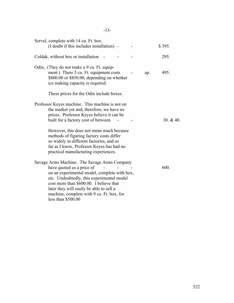
522
-13- Servel, complete with 14 cu. Ft. box. (I doubt if this includes installation) - - $ 395. Coldak, without box or installation - - - 295. Odin, (They do not make a 9 cu. Ft. equip- ment.) There 5 cu. Ft. equipment costs - ap. 495. $800.00 or $850.00, depending on whether ice making capacity is required. These prices for the Odin include boxes. Professor Keyes machine. This machine is not on the market yet and, therefore, we have no
prices. Professor Keyes believe it can be built for a factory cost of between - - 30. & 40. However, this does not mean much because methods of figuring factory costs differ so widely in different factories, and so far as I know, Professor Keyes has had no practical manufacturing experiences.
Savage Arms Machine. The Savage Arms Company have quoted us a price of - - - 600. on an experimental model, complete with box, etc. Undoubtedly, this experimental model cost more than $600.00. I believe that
later they will easily be able to sell a machine, complete with 9 cu. Ft. box, for less than $500.00

523
MR. E. W. Rice, Jr., Schenectady.
Type OC-2 Form E Refrigerating Machine #10035.
Shipped March 26, 1921. Put into operation April 14, 1921. Thermostat spring adjusted to reduce the running time May 1st, May 6th, and May 10th. No interruption to service. Increased the quantity of cooling water on May 27th, and June 25th. No interruption to service. Thermostat adjusted for lower refrigerator temperature on July 12th. No interruption to service. Trouble with water valve on Aug. 5th and Aug. 9th. About eight (8) hours interruption each time. Temperature in the refrigerator not above normal. Trouble with water valve on Aug. 16th, Aug. 19th, and Aug. 23rd. No interruption to service. This was one of the first machines sent to Schenectady. It was equipped with the round copper brine tank with small freezing space under the tank, and with the first forms of the thermostat and the water valve. The bulb of the thermostat was placed outside of the brine tank. It was found that better results could be obtained by placing the bulb of the thermostat in the brine tank. This gave better control of the temperatures, thus decreasing the number of adjustments necessary. Later models were built in this way. It was also found that much of the sparking and chattering of the thermostat could be overcome by extending the lever which carried the contact points and providing it with an insulated block which worked between two adjustable pins, so that when the insulated blocked touched one of the pins the lever would flex in order to make the contact. The design of the thermostat was changed accordingly. Several improvements were made in the water control valve as experience indicated that they were desirable. The valve on this machine was equipped with a rubber washer fastened to the stem with shellac. In several instances theses washers came loose from the stem and clogged up the valve, thus shutting off the flow of cooling water. This happened on machine #10035 on Aug. 5th and again on Aug. 9th (noted above) and on each of these dates

524
the valve stem and washer were removed and replaced by another stem and washer of the same design. This last stem did not seat perfectly and the valve did not always close off completely. This was noticed on Aug. 16th, 19th, and 23rd (noted above). In the later design of water vale this washer is threaded into place. The air cooled machine, of course, has no water valve. It was found that the round brine tanks did not provide sufficient cooling surface and that a square tank with more cooling surface -2- could be put into the same size cooling compartment. It was also found that the copper tanks were not satisfactory, due to an odor probably caused by the oxidation of the copper. The next tanks were made of sheet steel. It was also found that the freezing compartments placed under the tanks, with only the tap of the freezing compartment exposed to the brine, were very inefficient, and required very long freezing time. To overcome this an opening was out in the front of the later style square tanks and a freezing compartment welded in, in such a way that the top, bottom, back and two sides of the freezing compartment were exposed to the cold brine. Machine #10035, although still operative, was removed on Aug. 22nd and replaced by machine #10041, embodying the improvements above described. Machine #10035 was returned to the factory and brought up to date. Service was interrupted for about 2 ½ hours while machines where being changed. Brine temperature not above normal. - - - - - - - - - - - - - - - - - - - Type OC-2 Form E Refrigerating Machine #10041. Installed Aug. 22nd, 1921. Much trouble was experienced during the first week or two due to the thermostat not being in proper adjustment when the machine was shipped from the factory. On this account, service was interrupted about 36 hours from Aug. 23rd to 25th, about 40 hours from Aug. 27th to 29th and about 24 hours from Aug. 29th to 30th. This machine was shipped out with the thermostat in this shape because Mr. Orr expected to be in Schenectady and wanted to try adjusting the thermostat when the machine was installed, but due to a change in plans he did not go to Schenectady at that time and there was a misunderstanding whereby Mr. Riffle thought that the thermostat had been adjusted at the factory.

525
The brine tank of this machine was filled with a solution of glycerine in water. This had been suggested as an improvement over the salt solution and it was being tried out at that time. It was found that the glycerine would freeze out of solution and that the brine tank could not be maintained at the proper temperature without having the machine operate with extremely lower evaporator temperature. This operating at low temperature caused trouble when the automatic device would close the circuit to start the machine, that is, at the time of starting there would be an overload on the machine which would stall the motor and bring into play the overload device. Service was interrupted in this way for about 3 hours on Sept. 15th and for about 60 hours from Sept. 16th to Sept. 19th. In spite of the fact that the evaporator was very cold, the brine tank was not cold enough, therefore the ice which had been frozen was often found to be melted before it was removed from the machine. The glycerine solution was abandoned and the brine tank filled with a salt (NaCl) solution on Oct. 3rd, 1921. No interruption to service on this date. A different adjustment of the thermostat was then found to be necessary. This was made without interrupting service. This machine was equipped with a water valve which was actuated by -3- a sylphon bellows which operated as a function of the temperature of the water in the water jacket of the machine. Due to the fact that it required some time for the water in the jacket to warm up there was a considerable time lag between the operation of the machine and the operation of the water valve, so that the machine would run for some little time before the flow of cooling water was started, therefore it would build up a high condenser pressure. Therefore, this type of water valve caused erratic action of the machine. These high pressures caused the machine to use an excessive amount of current and sometimes caused the overload device to stop the machine. The overload tripped on Oct. 21st. Service was interrupted for about 12 hours. The buzzer did not sound because of a loose lead. Service was again interrupted in this way for about 56 hours from Oct. 22nd to Oct. 25th. The thermostat was adjusted on Nov. 16, 1921. No interruption to service.

526
On Dec. 20, 1921, the water valve was adjusted so as to make it open sooner after the starting of the machine. No interruption to service. On March 21, 1922, the water valve was again adjusted. No interruption to service. April 18th, water valve completely out of service. No interruption to the operation of the machine. The water was allowed to flow continuously through this machine until the machine was replaced on Nov. 21st. The later type of water valve operates as a function of the pressure in the compressor so that there is practically no lag in its operation. This type of valve is much more satisfactory. April 19th, thunderstorm caused a disturbance on the power lines. The overload device shut down the machine. The overload was not reset until after about 14 hours interruption. The next trouble encountered was with the overload device which was adjusted to trip on too low a current. This caused interruption to the service for about 47 hours from April 13th to 15th and for about 8 hours on May 2nd. The adjustment of the overload was changed on May 9th. No interruption. On July 18th the thermostat was found to be leaking. A new thermostat was installed. No interruption to service. On Aug. 14th the thermostat was adjusted to reduce the temperature in the refrigerator. No interruption. On Oct. 31st the water pipes were flushed out and the water supply was adjusted. No interruption. The sheet steel brine tank on this machine had been painted with a special paint adapted to withstand the severe conditions of humidity and temperature. However, these tanks rusted very badly and the next development was a steel tank covered inside and outside with

527
-4- a vitreous enamel. Due to the condition of this brine tank and to the fact that at this time all machines were being replaced with rebuilt machine, embodying other refinements of design, this machine was replaced on Nov. 21st, 1922 with machine #10031. Service was interrupted for about one hour while the machines were being changed. Machine #10041 was returned to the factory and rebuilt, being brought up to date. - - - - - Type OC-2 Form F Refrigerating Machine #10031. Installed Nov. 21, 1922. The relay was out of order Dec. 3rd and 4th. Service was interrupted for about 24 hours. The machine was shut down from Dec. 5th to Dec. 12th to see if it was needed during the winter months. The water valve was adjusted Dec. 13th. No interruption. The water valve was cleaned Jan. 30, 1923. No interruption. The charts on this machine show some long idle periods during the Spring of 1923, apparently for the purpose of defrosting. They do not show any notation of trouble. The demand motor was taken out of service on May 1, 1923. The machine failed on May 19th and was replaced by machine #10015. Machine #10031 would not produce any appreciable amount of refrige- ration at the time it was removed from this installation, but when it was received in Fort Wayne it had a normal refrigerating capacity. This trouble was due to a defective water valve, the plunger being of an absolute design, it having a short housing for the rubber seat which allowed the seat to come loose from the housing. The valve should have been equipped with a plunger having a longer housing but the old style plunger was put in through an oversight in the factory. The rubber seat coming loose, plugged up the valve and stopped the flow of cooling water, thus causing the machine to build up an excessive pressure in the condenser with the result that the oil, which normally forms a seal around the float valve, was forced through into the evaporator so that the machine would not function any longer. The jarring of the machine during transportation, caused

528
some of the oil to run down from the compressor case and again seal the float valve so that the machine operating normally when it was received in Fort Wayne. However, after the machine had been running for some time in Fort Wayne, the water valve again caused the same trouble and it was then found that the valve was defective.
- - - - - - Type OC-2 Form E Refrigerating Machine #10015. Installed May 19th, 1923. This was one of the first machines shipped to Schenectady, and it -6- put on this installation temporarily and with the understanding that it would be replaced as soon as a machine for this installation was received from Fort Wayne. It was replaced June 14, 1923, be machine #10036. - - - - - Type OC-2 Form G Refrigerating Machine #10036. Installed June 14th. In operation to date. (Oct. 11, 1923.) No reports of trouble.
529
Apopendix 71
MANNESMANN TIEF KUHLSCHRANK * * * * * * * * * * * * * *
(1) Name of manufacturer – Mannesmann Industrie and Handelagesellschaft M. B. H.
(2) Address – Berlin W. 50, Tauentzienstrasse 19A.
This machine is of the absorption type and
was invented by Dr. Rumpler. This Company has apparently
done quite a business. They furnish a pamphlet with thirty-
three references from satisfied users. Their representative
for Great Britain, Ireland, Canada, and British India is
H. Barash, 30 Mincing Lane, London, E. C. 3.
This machine is very simple, as will be seen
from the detailed description of the apparatus and its ope-
ration at the end of this appendix. The refrigerator boxes
are particularly interesting because they apparently have
5.9” of cork insulation. Due to this very thick insulation,
a very small refrigerating machine is able to maintain a tem-
perature of 39° in the box, and make 5 lbs. of ice a day
(this 5 lbs. can be frozen in two hours).
The most interesting thing about the machine
is that it is very cheap; the smallest size has a net resale
price, f.o.b. Hamburg, including export license and export
duty of $82.00. The import duty into this country would
probably be 40%. The cost of the refrigerating machine in
this country, neglecting ocean freight, would be $112.00.
The resale price of the box, f.o.b. Hamburg,
including export license and export duty, is $41.00. The

530
-2-
duty on the box would be 33 1/3%. Therefore, the price
of the box in New York, neglecting ocean freight, would
be about $55.00. This makes a total price for box and
machine of $167.00. This is the smallest size, and the
capacity is only 4 cu. Ft. Assuming a 40% discount, this
would be a selling price of around $280.00 for the ma-
chine and box. The Frigidaire 5 cu. Ft. machine and box,
Model B-5, sells for $495.00
This model runs on 2 KW-hours a day an
106 gallons of water a day, while the Frigidaire, Model
B-5, takes approximately 75 to 150 gallons of water a day.
An absorption machine of this kind is inherently very in-
efficient, but the power consumption is kept down to a
reasonable figure by the 5.9” of insulation.
These prices are very interesting because
they are so low, but Mr. Henshaw tells me that they are no
lower than he would have expected considering the low cost
of labor in Germany. He feels that we should not take the
low price of these machines as an indication of superiority
in design.
This Company makes these refrigerators in
two styles, one for temperate climates and one for tropi-
cal climates. The machine is water cooled and in temperate
climates they expect the cooling water to be between 50 and
54 degrees, whereas the machine for tropical climates is
designed for use with cooling water as warm as 77 degrees
Fahrenheit. This indicates a possible disadvantage of the
(Ed. NOTE: page 3: Picture and Diagrams too dark to copy)
531
-4-
machine because in the southern parts of our own country
the city water supply runs, in hot weather, as high as
100 degrees.
DESCRIPTION OF CONSTRUCTION AND OPERATION (See Sketch)
A. The Box
Special technical consideration has been
given to the construction of the box with a view to ob-
taining good insulation. It is constructed of double walls,
the inner sides of which are covered with insulating paper
between which insulating material, high grade cork slab is
firmly pressed in. The inner space is covered according to
requirements with zinc, glass, or tiles, and contains de-
tachable shelves, as shown in the picture. There is a small
waster pipe in the bottom of the box to drain off melted
frost. All five types shown in the foregoing table are
supposed to have 150 mms. of insulation. This is equiva-
lent to about 5.9”. The pamphlets claim that the machine
is capable of maintaining a temperature of 39 degrees Fah-
renheit inside the box.
The foregoing table shows that the ratings
of the machines are very small; therefore, the insulation
must be pretty good, if a temperature of 39 degrees is main-
tained. All this, taken together with the low price given
in the foregoing table would seem to indicate that the boxes
are remarkably inexpensive, considering their supposed
quality.

532
-5-
B. Refrigerating Apparatus
The refrigerating apparatus is fixed in and
on the box and is easily removable. The following are the
principle parts of the apparatus:
1 – Boiler (No. 1)
The boiler (absorber) consists of a small
tank, inside of which is fixed a pipe (No. 2), through
which cooling water passes during the later period of ab-
sorption. In the case of electrical heating, two tubes
pass through the bottom of the boiler and form containers
for the heating elements (No. 3), afterwards referred to
as heaters.
2 – Automatic Disconnector (No. 4)
This serves the purpose of cutting off the
current at the end of the heating period and turning the
cooling water through the absorber. It consists of the
following three parts:
a) A membrane (No. 5)
b) A water diverter (No. 8)
c) A service lever (No. 6)
It can be seen in the sketch that there is
inserted into the boiler a tube (No. 5a). This is filled
with water and is connected to the membrane (No. 5). When
the boiler is heated to the proper temperature, the water
in this pipe boils and causes a pressure on the membrane
which trips the service lever (No. 6), allowing the weight
533
-6-
to turn it around the hinge (No. 6b). The movement of
this lever produces the following effects:
a) The current is cut off at the contact (No. 7).
b) The water flowing from the cool- ling water container (No. 17) through the pipe (No. 17a) be- comes diverted from funnel 17b into funnel 17c, from which it flows through the cooling pipes (No. 2) in the absorber.
3 – Water Separator (No. 9)
this is a small tank placed in the cooling
water container (No. 17) and connected with the boiler
(No. 1) by a pipe (No. 1a). Any steam which goes over
with the ammonia vapor from the boiler is condensed out
and settles in the form of water in the bottom of this
water separator. When the apparatus is reversed, this
water is blown back into the boiler.
4 – Condenser (No. 10)
This consists of a coiled pipe situated in
the water container (No. 17).
5 – Evaporator (No. 11)
This consists of an upper manifold and a
lower manifold connected by vertical tubes. The liquid am-
monia evaporates in this, this causing the refrigerating,
(No. 12) is an ice cell in the form of a detachable metal
cup, where a small block of pure ice is formed (I under-
stand that 5 lbs. of ice can be made in two hours).
6 – Ammonia Threeway Valve (No. 14)
This is fixed in the connection between the

534
-7-
water separator (No. 9) and the condenser (No. 10), and
the valve has also a direct connection with the lower
manifold of the evaporator (No. 11).
C. Operation of the Plant
The boiler (No. 1) will be heated when the
service lever (No. 6) is pressed downwards to the position
“ON”, and the solution contained therein will be brought
up to the temperature of 230 degrees Fahrenheit. In this
way, the ammonia vapor is boiled out of the water and leaves
through the pipe (No. 1a), going through the water separator
(No. 9) into the condenser (No. 10). Due to the pressure
and the influence of the cooling water, the vapor in the
condenser is liquefied and the liquid ammonia flows through
the pipes into the evaporator (No. 11). As the ammonia
boils out of the water, the boiling temperature of the solu-
tion rises. When it has reached 230 degrees, the pressure
of the steam in the inserted pipe (No. 5a) is sufficient to
push the diaphragm (No. 5), thus moving lever (No. 6),
bringing the “heating period” to an end. The heating period
lasts about 1 ½ hours (the plant can be heated by either
electricity, gas, paraffin oil, petrol, spirit, wood, or
coal, for which cases specially constructed heaters are pro-
vided). The cooling period starts automatically at the end
of the heating period and lasts for about twenty-four hours.
The water from container (No. 17) is diverted
to the funnel (No. 17c) by the automatic disconnecter. From

535
-8- there it passes through the cooling pipe (No. 2) through
the boiler (No. 1) and the outlet pipe (No. 15). The run-
ing water causes the contents of boiler (No. 1) to be
quickly cooled. At this low temperature, the water absorbs
ammonia vapor, thus reducing the pressure. This reduction
in pressure causes a suction from the evaporator (No. 11),
which evaporates the liquid ammonia. The evaporation of
the liquid ammonia causes the refrigeration. The evapora-
tion takes about twenty-four hours, during which time the
ammonia vapor flows back from the evaporator into the
boiler where it is absorbed by the water. At the end of
about twenty-four hours, the mixture in the boiler will
again contain the same proportions of water and ammonia as
at the beginning of the heating period. The evaporation
of the ammonia in the evaporator produces a temperature in-
side the evaporator as low as minus four degrees Fahrenheit.
This is sufficient to maintain an average temperature in the
box of about 39 degrees Fahrenheit.
Data Folder #1183 contains all the printed
pamphlets on this refrigerating machine, and anyone desir-
ing further information should refer to this Data Folder
which has quite complete instructions for installation, ope-
ration, repairs, etc.
One fact interested me particularly. Under
“Installation”, it is mentioned that the apparatus can be
installed in any room, but the room must be free from frost
536
-9-
during the winter to avoid frosting the water supply.
For the efficient working of the refrigerator it is natu-
rally desirable to select not to warm a room. For this
reason, it is desirable to avoid the vicinity of a hot
stove or a spot where it would be exposed to the direct
rays of the sun.
The paragraph “Starting the Refrigerator”,
is also of interest. Although the heating period ends
automatically, the heating period must be started by hand.
Two heating periods must never immediately follow one ano-
ther. A new heating period may be started only when no
frost is noticeable on the evaporator (No. 11). There must
be an interval of at least twelve hours between two heating
periods. Generally, heating has to be done only once a day.
Overheating is also of interest. Should the
automatic disconnecter fail to cut off the electric current,
then the apparatus would boil over – that is to say, not only
will ammonia be driven out of the boiler (No. 1) into the
evaporator, but also a certain amount of water in the form
of steam. If great quantities of water are boiled over,
they will not be removed in the water separator and some
water will go into the evaporator. If the evaporator con-
tains both water and ammonia, no refrigeration can take
place because the contained in the evaporator absorbs
the ammonia and prevents it from evaporating. This trouble
can be remedied by turning the ammonia threeway tap. Imme-
diately after the end of the period of heating, the ammonia

537
-10-
threeway tap (No. 14) should be turned in such a way
that the handle rests firmly on the inscription “Open”.
The reduction in pressure in the boiler sucks the water
in the bottom manifold of the evaporator back into the
boiler. This return flow last about 120 minutes, during
which time the ammonia tap (No. 14) should remain in the
Open position, after which the ammonia tap (No. 14) should
be brought back to its original position. Even if the
machine does not boil over, a certain amount of water is
carried into the expansion coils and the above operation
should be performed regularly once a month as a precau-
tion to insure the highest efficiency of the plant.
Since the refrigerating medium is contained
in a hermetically closed system, it is never necessary to
replenish the supply of ammonia or water inside the system.

538
APPENDIX #71-A
INFORMATION FURNISHED BY MR. STUART OTTO
ON MANNESMANN MACHINE
________________
Mr. Stuart Otto told me that the Mannesmann
booklets do not show the complete arrangement of their refri-
gerating machine. The hand operated lever is arranged with a
stuffing box so that the tube connecting the generator with
the evaporator will be above the surface of the liquid during
the boiling period and will be below the surface of the liquid
during the absorbing period. This is quite a complicated piece
of apparatus which was patented by Dr. Rumpler. Mr. Otto had
several of these Rumpler machines and experienced difficulty
with this stuffing box arrangement. As described in the appen-
dix on the Otto machine, he has a patent which does away with
the necessity of this device.
Mr. Otto also said that the boxes furnished
with the Mannesmann machine were very poor workmanship, and
that the lining consisted of ordinary white paint on sheet
metal and that the paint cracked off quite rapidly.
ARStevenson, JR-DW
February 19, 1924.

539
APPENDIX #72
KLEINKALTE MASCHINEN
*************
(1) Name of manufacturer – A. Borsig
(2) Address – Berlin – Tegel.
(3) Remarks – The Publication Department has a bulletin on this
machine. It does not look very interesting, and is apparently
a small ammonia compression machine.
540
APPENDIX #73
POLARIS
______________
Manufactured by: Bayer Bros., Special Manufacturers of Small
Refrigerating Machines, Augsburg, Germany.
This is an ammonia and water aborption ma-
chine. The following information is taken from their bulletin.
The box interior is automatically cooled from 35.6° to 39.2°
Fahrenheit. The machine is always ready to operate without any
noise or smell, or wear and tear, and without any repairs or
successive refilling with refrigerant.
The supply of cooling water is as pure at the
exit as at the entrance, and can afterward easily be used for
other household purposes.
The Polaris can be installed anywhere where
there is cold running water and electric power or gas. The in-
stallation consists merely of connecting up the water pipes and
the electric or gas, after which the refrigerator is ready for
use.
The voltage of the existing power system should
be given when placing an order.
Size Trade Name Outside Measure Inside Measure Cubical Contents Wide:High:Deep Wide:High:Deep Useful Space: Outside Cu. Ft. : Cu. Ft.
1 Nanson 42” : 49” : 27” 28” :32.5”: 16” 8.5 32
1 Hodin 65” : 71” : 36” 51” :39.4”:23.6” 27.5 160
541
-2-
Weight-Lbs. KW-hrs. Cooling Water Size Box Absorber Together Shipping Wt. per day per day 1 620 132 750 860 1.9 66 Gallons 1 1250 350 1600 1760 4.5 212 Gallons Terms: Half the purchase price payable with the order and the rest on deliverance of shipping papers. The Polaris has a rather interesting slogan, “Through Heat to Cold”. Description: a- Absorber
The cooling unit proper consists of: 1 – Boiler 2 – Condenser 3 – Evaporator All of these parts are firmly fastened together, but the follow-
ing parts are built separately: the electrical control, the heat-
ing catridge, two water valves and the ice cell. The boiler is
shipped full and ready for use. The charge consists of water and
ammonia. The heating period is started by a lever and lasts
about 1 ½ hours. The heat causes almost complete evaporation
of the ammonia which, in the form of vapor, is driven to the con-
denser. The condenser is in the form of a double pipe spiral,
where the gas is liquefied by a counter current of cold water.
The liquid ammonia collects in the evaporator which is arranged
inside the refrigerator box. When a certain high temperature in
the boiler is arrived at, the heat is automatically shut off and
cold water is deflected, so that it no longer runs through the
condenser, but instead runs through the cooling pipes in the in-

542
-3-
terior of the boiler. The weak solution of ammonia and water
in the boiler tries to saturate itself with ammonia, and thus,
the ammonia vapor is sucked back from the evaporator. This
absorption causes the evaporation of the liquid refrigerant in
the evaporator and thus cools the refrigerator box. The eva-
porator itself reaches a temperature below freezing and this
causes the fresh water in the ice cell to freeze. The evapora-
tion or absorption period lasts about 22 hours.
b- Box
The refrigerator box “Polaris” is solid and
beautiful, built with 4 ¾” strong pressed cork insulation.
The interior is covered with white enamel on pressed artificial
stone, or covered with strong glass. The box is shipped com-
plete with the absorber ready for operation.
The description of this machine sounds very
similar to the Mannesmann. I should not be surprised but that
it will turn out that it is built under the same Rumpler patents.
Neither the Mannesmann description nor the Polaris description
mentions the most important feature of Dr. Rumpler’s patents,
namely the movable pipe which, during the heating period, is
above the surface of the liquid in the boiler and acts as out-
let for the ammonia vapor, and which, during the cooling period,
is below the surface of the liquid in the boiler and acts as
the inlet for the ammonia vapor during the absorption period.
The fact that this machine is started by means of a lever elads
me to believe that this lever probably operates such a device
through a stuffing box.
ARStevenson, Jr-DW
February 29, 1924.
543
APPENDIX #74
HACCIUS & BISCHOF
_______
French patent #564,622, granted to the above
men on January 8, 1924, has the following claim.
An electrically driven refrigerating machine
in which the driving motor is enclosed in a space separate
from the outside air, and filled with an inert gas which is
inoffensive to the operation of the motor. This motor compart-
ment is in open communication with the interior of the refri-
gerating machine, so that the pressure of the gas in the motor
compartment will conform itself to the pressure of the refriger-
ant, so that any of the refrigerant penetrating into the motor
compartment will be in a super-heated state.
The machine can be made in several different
ways, as follows:
1 – The air or inert gas in the motor compart-
ment is separated from the refrigerant by a neutral fluid, the
specific gravity of which is less than that of the liquid refri-
gerant – for example – oil. This liquid will prevent, to a cer-
tain extent, the interpenetration of the refrigerant with the
inert gas or air in the motor compartment, while at the same
time it will allow the pressure to equalize.
2 – The motor compartment, filled with air or
inert gas, is in open communication with either the compression
544
-2-
or expansion part of the refrigerating machine by an equalizing
pipe.
3 – The motor compartment, filled with air or
gas, is surrounded by a space filled with liquid, or is sur-
rounded by a compartment filled with the refrigerant, so that
any small losses through the pores of the metal or joints will
be from a compartment containing the refrigerant and will pre-
vent a loss of the charge to the outside.
4 – The shaft between the motor and compressor
turns in a bath oil which serves as a liquid seal between the
refrigerant and the charge of air in the motor compartment.
ARStevenson, Jr-DW
February 29, 1924.
END OF APPENDIX SECTION END OF DOCUMENT