report on 1d inversion modelling of the quest west ... · sub-block distribution for ... summary of...
TRANSCRIPT

Report on 1D Inversion Modelling of the Quest West Helicopter-Borne AeroTEM System Electromagnetic
Data
Aeroquest Job # 08130
Quest West Central B.C., Canada
For
by
7687 Bath Road, Mississauga, ON, L4T 3T1
Tel: (905) 672-9129 Fax: (905) 672-7083 www.aeroquest.ca
Report date: April, 2009

Report on 1D Inversion Modelling of the Quest West Helicopter-Borne AeroTEM System Electromagnetic
Data
Aeroquest Job # 08130
Quest West Central B.C., Canada
For
Suite 440 – 890 West Pender Street Vancouver, British Columbia
V6C 1J9, Canada
By
7687 Bath Road, Mississauga, ON, L4T 3T1
Tel: (905) 672-9129 Fax: (905) 672-7083 www.aeroquest.ca
Report date: April 2009

TABLE OF CONTENTS
TABLE OF CONTENTS ..................................................................................................I
LIST OF FIGURES...........................................................................................................I
LIST OF TABLES.............................................................................................................I
1. INTRODUCTION ........................................................................................................ 1
2. INVERSION PROCEDURE ....................................................................................... 1 2.1. SUMMARY ........................................................................................................................................... 1 2.2. FINAL MODELS .................................................................................................................................... 3
3. DELIVERABLES ......................................................................................................... 4 3.1. DIGITAL DELIVERABLES...................................................................................................................... 4
3.1.1. Final Database of Survey Data (.GDB) ...................................................................................... 4 3.1.2. Geosoft Voxel Models ................................................................................................................. 5 3.1.3. Digital Versions of Final Maps (.MAP, .PDF) ........................................................................... 5 3.1.4. Free Viewing Software (.EXE).................................................................................................... 5 3.1.5. Digital Copy of this Document (.PDF) ....................................................................................... 5
4. INVERSION RESULTS............................................................................................... 5 4.1. SYSTEM DEFINITION ............................................................................................................................ 5
4.1.1. Waveform .................................................................................................................................... 6 4.1.2. Loop Definition ........................................................................................................................... 6 4.1.3. Data ............................................................................................................................................ 6 4.1.4. Noise ........................................................................................................................................... 6
4.2. INVERSION PARAMETER SELECTION .................................................................................................... 6 4.2.1. Importance of Accurate Noise Estimates .................................................................................... 6 4.2.2. Importance of Reference Model .................................................................................................. 6 4.2.3. Importance of Inversion Algorithm............................................................................................. 7 4.2.4. Importance of General Measures for Model Norm Structure ..................................................... 8
APPENDIX 1: DESCRIPTION OF DATABASE FIELDS........................................ 10
LIST OF FIGURES Figure 1. Sub-block distribution for Block 1.. ................................................................... 2 Figure 2. Sub-block distribution for Block 2.. ................................................................... 3 Figure 3: EM1DTM inversion models for the Huckleberry infill survey,......................... 4
LIST OF TABLES Table 1. List of sub-block names. ...................................................................................... 1 Table 2. Summary of the reference models used in the inversion process.. ...................... 7 Table 3. Summary of the inversion method parameters used for each inversion area....... 8
Aeroquest Limited – Report on 1D Inversion Modelling of the Quest West Helicopter-Borne AeroTEM Electromagnetic Data i
1. INTRODUCTION This report describes the EM1DTM Inversion modelling carried out on the AeroTEM electromagnetic data from Geoscience BC’s Quest West Project. The Quest West project covers an area of over 40,000 square kilometers from Vanderhoof and Fort St. James to Terrace and Kitimat in British Columbia. The total survey coverage was 13,219.1 line-km The survey was made up of two blocks, Block 1 Zone 9 and Block 2 Zone 10 (12,539.8 line-km in total), with six infill areas (679.3 line-km in total) within the two blocks. The two blocks were flown at a 4,000 metre line spacing, and the infill areas were flown at a 200 metre line spacing. The report entitled “Report on a Helicopter-Borne AeroTEM System Electromagnetic & Magnetic Survey, Aeroquest Job # 08130” submitted to Geoscience BC in January 2009 describes the survey logistics, the data processing, the presentation of the final data, and provides detailed specifications of the survey.
2. INVERSION PROCEDURE
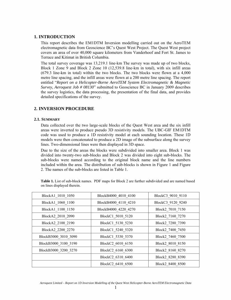
2.1. SUMMARY Data collected over the two large-scale blocks of the Quest West area and the six infill areas were inverted to produce pseudo 3D resistivity models. The UBC-GIF EM1DTM code was used to produce a 1D resistivity model at each sounding location. These 1D models were then concatenated to produce a 2D image of the subsurface along the survey lines. Two-dimensional lines were then displayed in 3D space. Due to the size of the areas the blocks were subdivided into smaller area. Block 1 was divided into twenty-two sub-blocks and Block 2 was divided into eight sub-blocks. The sub-blocks were named according to the original block name and the line numbers included within the area. The distribution of sub-blocks is shown in Figure 1 and Figure 2. The names of the sub-blocks are listed in Table 1. Table 1. List of sub-block names. PDF maps for Block 2 are further subdivided and are named based on lines displayed therein.
BlockA1_1010_1050 BlockB4000_4010_4100 BlockC3_9010_9110
BlockA1_1060_1100 BlockB4000_4110_4210 BlockC3_9120_9240
BlockA1_1100_1150 BlockB4000_4220_4270 Block2_7010_7150
BlockA2_2010_2090 BlockC1_5010_5120 Block2_7160_7270
BlockA2_2100_2190 BlockC1_5130_5230 Block2_7280_7390
BlockA2_2200_2270 BlockC1_5240_5320 Block2_7400_7450
BlockB3000_3010_3090 BlockC1_5330_5370 Block2_7460_7500
BlockB3000_3100_3190 BlockC2_6010_6150 Block2_8010_8150
BlockB3000_3200_3270 BlockC2_6160_6300 Block2_8160_8270
BlockC2_6310_6400 Block2_8280_8390
BlockC2_6410_6500 Block2_8400_8500
Aeroquest Limited – Report on 1D Inversion Modelling of the Quest West Helicopter-Borne AeroTEM Electromagnetic Data 1
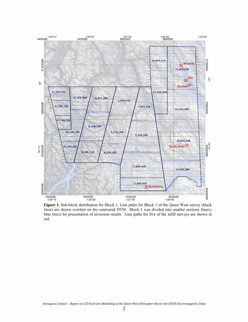
Figure 1. Sub-block distribution for Block 1. Line paths for Block 1 of the Quest West survey (black lines) are shown overlain on the contoured DTM. Block 1 was divided into smaller sections (heavy blue lines) for presentation of inversion results. Line paths for five of the infill surveys are shown in red.
Aeroquest Limited – Report on 1D Inversion Modelling of the Quest West Helicopter-Borne AeroTEM Electromagnetic Data 2
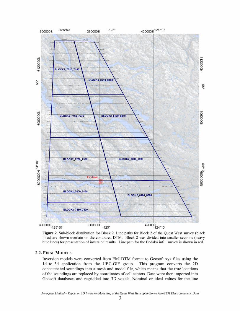
Figure 2. Sub-block distribution for Block 2. Line paths for Block 2 of the Quest West survey (black lines) are shown overlain on the contoured DTM. Block 2 was divided into smaller sections (heavy blue lines) for presentation of inversion results. Line path for the Endako infill survey is shown in red.
2.2. FINAL MODELS Inversion models were converted from EM1DTM format to Geosoft xyz files using the 1d_to_3d application from the UBC-GIF group. This program converts the 2D concatenated soundings into a mesh and model file, which means that the true locations of the soundings are replaced by coordinates of cell centers. Data were then imported into Geosoft databases and regridded into 3D voxels. Nominal or ideal values for the line
Aeroquest Limited – Report on 1D Inversion Modelling of the Quest West Helicopter-Borne AeroTEM Electromagnetic Data 3

northing (or easting in certain cases) were used for gridding. Although the inversion models were gridded in 3D, the blanking distance was reduced so that the resulting voxels consisted of 2D lines displayed in 3D rather than interpolated 3D volumes. The line spacing of Blocks 1 and 2 is too large to allow for gridding in three dimensions. The detailed infill survey inversion models can be gridded in 3D, but such interpolated volumes are not provided as part of this report. An example of the final model from the Huckleberry infill area is shown in Figure 3.
Figure 3: Concatenated EM1DTM inversion models for the Huckleberry infill survey, displayed in 3D space. The values on the lower axes represent the eastings and northings in Nad83 Zone 9 and indicate scale of the survey. The values on the vertical axis represent the elevation of the soundings.
The UBC-GIF EM1DTM files have been delivered to Geoscience BC for archival purposes but are not included with this report.
N
3. DELIVERABLES
3.1. DIGITAL DELIVERABLES
3.1.1. Final Database of Survey Data (.GDB) The 1D models are archived digitally in a Geosoft GDB binary format database. A description of the contents of the individual channels in the database can be found in Appendix 1. A copy of this digital data is archived at the Aeroquest head office in Mississauga.
Aeroquest Limited – Report on 1D Inversion Modelling of the Quest West Helicopter-Borne AeroTEM Electromagnetic Data 4

Aeroquest Limited – Report on 1D Inversion Modelling of the Quest West Helicopter-Borne AeroTEM Electromagnetic Data 5
3.1.2. Geosoft Voxel Models Geosoft format voxel models of the pseudo 3D resistivity models for each area or section thereof are included.
3.1.3. Digital Versions of Final Maps (.MAP, .PDF) Map files in Geosoft .map and Adobe PDF format for each area or section thereof are included.
3.1.4. Free Viewing Software (.EXE)
Geosoft Oasis Montaj Viewing Software Adobe Acrobat Reader
3.1.5. Digital Copy of this Document (.PDF) Adobe PDF format of this document.
4. INVERSION RESULTS As with any inversion, there are many factors that contribute to the final model that is recovered. These factors include reference model, noise estimates on the data, level of data misfit achieved and the inversion methodology selected. An exhaustive exploration and discussion of the rationale behind the selection of the various parameters would fill an entire report. The “final” inversion results presented here are one possible model that is geologically and geophysically plausible.
4.1. SYSTEM DEFINITION The first step in the inversion process is characterizing the EM system that was used to collect the data. This includes shape of the waveform, transmitter-receiver geometry (shape, size, location and orientation), measurement windows and estimates of the measurement noise. The waveform is monitored and recorded throughout the survey and the measured waveform is used in the system definition. The shape and size of the transmitter and receivers are well known and are assumed to be constant throughout the survey. Due to the rigidity of the AeroTEM frame, the location of the transmitter and receiver relative to one another is assumed to be fixed throughout the survey. Transmitter location relative to the earth’s surface is determined using the altitude measured using a GPS on the tow cable, an altitude measured with a radar altimeter mounted on the helicopter and the assumed position of the bird relative to the helicopter (based on the tow cable length and the angle of the cable in flight). The orientation of the transmitter and receiver are assumed to be horizontal throughout the survey. Measurement noise of the system operating at 90 Hz is approximately +/- 10 nT/s. However, when defining noise estimates in the inversion scheme it is important to realize that any characteristics of the system that are seen in the data but are not captured in the data must also be considered as noise. Hence, the general practice is to assign a percentage of the data and a noise floor. The percentage will deal with the modelling error and the noise floor is the actual system noise. The system parameters for AeroTEM III are listed in the following sub-sections.

4.1.1. Waveform The waveform was defined to reproduce the actual waveform measured by the system while on survey. Effective current is the number of turns (5) times current (455 A). The pulse width was 1,833 μs wide.
4.1.2. Loop Definition The transmitter loop is a 12-sided polygon 10 m in diameter.
4.1.3. Data Sixteen channels of Z component off-time data were used for the inversion. The first off-time gate was not included in the inversion modelling. While it does contain qualitative information of the shallow sub-surface it was difficult to fit with the inversion algorithm. Line data were averaged over 50 soundings (approx 150 m sounding spacing) for the Quest West blocks and five soundings (less than 25 m sounding spacing) for the detailed infill surveys in order to reduce the number of station locations.
4.1.4. Noise Noise was generally estimated as 5- 10%, as was determined to be appropriate for each line, and a floor of 10 nT/s.
4.2. INVERSION PARAMETER SELECTION When inverting data to recover a 1D layered earth model, it is important to understand the non-uniqueness inherent in the problem, meaning that there are an infinite number of solutions that fit the data. Therefore it is not just important to fit the data but to also ensure that the recovered model is sensible. This usually involves inverting a given data point a number of times with a variety of error estimates and model constraints. Some of the issues involved are summarized in the following sub sections.
4.2.1. Importance of Accurate Noise Estimates Accurate noise estimates are crucial when using the EM1DTM codes in order to ensure that the model is expressing the conductive features measured in the data without having excessive and unjustified structure. As errors decrease, the resulting model becomes increasingly complex and amplitudes of the features therein increase as well. Errors need to be assigned that are appropriate for the system used to collect the data, the circumstances of the survey (e.g. ruggedness of topography) and the modelling algorithm while still allowing for a geologically reasonable amount of structure to be created in the model.
4.2.2. Importance of Reference Model The choice of reference model is important in an inversion, not only for ease of fitting the data. By running the same inversion with a variety of reference models, it is possible to determine the depth when the data are no longer influencing the inversion result. This is sometimes referred to as the depth of investigation. Inversion results have shown that the depth of investigation in some areas within the Quest West survey is about 300 m. The Quest West data were difficult to invert with a single reference model, as there are areas of conductive overburden and also very resistive outcrop. However, creating different reference models for each sounding such that reference models can vary along a line as necessary is an elaborate and time-consuming undertaking. The alternative is to use the half-space option in the EM1DTM codes but this does not always produce laterally coherent and reasonable models. Consequently, a single, relatively conductive
Aeroquest Limited – Report on 1D Inversion Modelling of the Quest West Helicopter-Borne AeroTEM Electromagnetic Data 6

reference model was chosen for both blocks of the Quest West survey and different reference models were selected for each of the six infill survey areas (Table 2). Models were then clipped at 350 m for the large-scale blocks and 400 m for the detailed infill surveys. Both cut-off depths likely overestimate the depth of investigation, however they are selected to provide useful information throughout the survey area.
Table 2. Summary of the various reference models used for inverting the large scale Quest West blocks and the detailed infill surveys over the known deposits. Selected lines from each area were inverted using a variety of reference models in order to determine the most appropriate value.
Survey Area Reference Model
Block 1 100 ohm-m
Block 2 100 ohm-m
Morrison 500 ohm-m
Bell 100 ohm-m
Granisle 100 ohm-m
Equity Silver 250 ohm-m
Huckleberry 500 ohm-m
Endako 250 ohm-m
4.2.3. Importance of Inversion Algorithm Four different inversion methods are available in the EM1DTM package. The choice of inversion algorithm is an important one and can affect the model results obtained. The most commonly used algorithm is the discrepancy principle. In this algorithm, the program tries to fit the data to within the prescribed noise estimates. This is accomplished by searching for a suitable regularization parameter, β, which results in a model that can fit the data while honouring the model constraints imposed by the user. There are other methods of finding an optimal β such as the L-curve and generalized cross validation (GCV). However, there are some cases where it is useful to invert the data using a fixed β value. One such case would be when the geology or noise characteristics along a survey line are varying such that it is not possible for the discrepancy principle to recover models that are reasonable in two dimensions. In such cases, it is useful to run the inversions using a sensible β value (usually selected from trial inversions using the discrepancy principle or L-curve method). This will result in a model that over- or under-fit the data along a given line but maintains a smooth appearance. The Quest West blocks were inverted using the discrepancy method in order to fit both the conductive and resistive areas to within the same error range. The detailed infill blocks were inverted with the fixed beta method as the geology and noise varied much less in these small areas. Different final betas were used for each area, as determined by trial runs with the discrepancy and L-curve methods. A summary of the inversion parameters is shown in Table 3.
Aeroquest Limited – Report on 1D Inversion Modelling of the Quest West Helicopter-Borne AeroTEM Electromagnetic Data 7
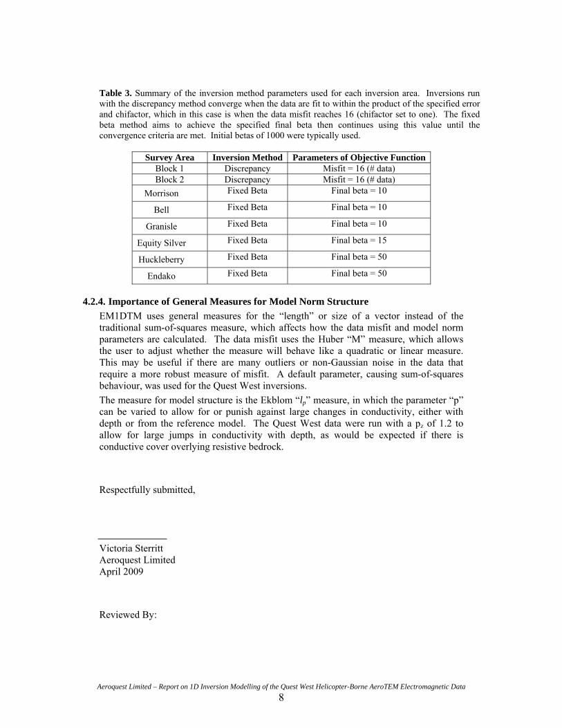
Table 3. Summary of the inversion method parameters used for each inversion area. Inversions run with the discrepancy method converge when the data are fit to within the product of the specified error and chifactor, which in this case is when the data misfit reaches 16 (chifactor set to one). The fixed beta method aims to achieve the specified final beta then continues using this value until the convergence criteria are met. Initial betas of 1000 were typically used.
Survey Area Inversion Method Parameters of Objective Function Block 1 Discrepancy Misfit = 16 (# data) Block 2 Discrepancy Misfit = 16 (# data)
Morrison Fixed Beta Final beta = 10
Bell Fixed Beta Final beta = 10
Granisle Fixed Beta Final beta = 10
Equity Silver Fixed Beta Final beta = 15
Huckleberry Fixed Beta Final beta = 50
Endako Fixed Beta Final beta = 50
4.2.4. Importance of General Measures for Model Norm Structure EM1DTM uses general measures for the “length” or size of a vector instead of the traditional sum-of-squares measure, which affects how the data misfit and model norm parameters are calculated. The data misfit uses the Huber “M” measure, which allows the user to adjust whether the measure will behave like a quadratic or linear measure. This may be useful if there are many outliers or non-Gaussian noise in the data that require a more robust measure of misfit. A default parameter, causing sum-of-squares behaviour, was used for the Quest West inversions. The measure for model structure is the Ekblom “lp” measure, in which the parameter “p” can be varied to allow for or punish against large changes in conductivity, either with depth or from the reference model. The Quest West data were run with a pz of 1.2 to allow for large jumps in conductivity with depth, as would be expected if there is conductive cover overlying resistive bedrock. Respectfully submitted,
Victoria Sterritt Aeroquest Limited April 2009 Reviewed By:
Aeroquest Limited – Report on 1D Inversion Modelling of the Quest West Helicopter-Borne AeroTEM Electromagnetic Data 8

Sean Walker Aeroquest Limited April 2009
Aeroquest Limited – Report on 1D Inversion Modelling of the Quest West Helicopter-Borne AeroTEM Electromagnetic Data 9

APPENDIX 1: DESCRIPTION OF DATABASE FIELDS The GDB file is a Geosoft binary database. A description of the fields in the database are shown below.
COLUMN UNITS DESCRIPTOR X m UTM Easting (Nad83, Zone 9 for Block 1 or Zone 10 for Block 2) Y m UTM Northing (Nad83, Zone 9 for Block 1 or Zone 10 for Block 2) Z m Elevation CON S/m Conductivity modelled by EM1DTM codes X_nominal m Ideal Easting for north-south trending survey lines (Nad83, Zone 9 or 10) Y_nominal m Ideal Northing for east-west trending survey lines (Nad83, Zone 9 or 10)
Aeroquest Limited – Report on 1D Inversion Modelling of the Quest West Helicopter-Borne AeroTEM Electromagnetic Data 10