report of internship - renater · pdf filereport of internship ... durand who help me and i...
TRANSCRIPT

Report of Internship
Netzahualcoyotl ORNELAS Period: 04/04/2005 to 30/09/2005
GIP RENATER
Multicast transmission in
VPN Networks (mVPN)
Master 2 Networks, Course Research Cycle 2004 - 2005
1

Thanks
would like to thank mainly and in particular to my two tutors Bernard Tuy and Jérôme
the same manner, I would like to thank Mr. Dany Vandromme (Director GIP Renater) to
thank to the SIPA’s team, with whom I had the opportunity of working and share of their
hanks to the administrative personal, the SSO department, the CERT of Renater whom share
o the University of Paris 6, “Pierre et Marie Curie”, for the formation within the framework
ast but not least, to my parents Ines María García Beltran and Victor Manuel Ornelas Lopez
hanks to all of you.
I Durand who help me and I had their support all the time during this internship for the good development of it, they were always in a good disposition to give me their advices and guide me by the right way, it allowed me to advance in the project and with whom I shared a good environment of ambiance and their friendship. Inaccept me to do this internship in the GIP Renater and that accepted the budget for this internship. I good humor in an enjoyable and convivial atmosphere of work. Ttheir experience in the work and in general to the good ambiance in the localities of Renater. Tof the Master Degree in Networks. Lwhom support me all the time from Mexico and that encouraged to me to follow ahead in this important project to conclude my studies. T
2

Introduction: ............................................................................................................................... 4
2. m
3. Test of an m
4. us
5. clu
1.16.
2.1
6.3.1
6.
1. General context of the Internship ........................................................................................... 5 1.1. RENATER ................................................................................................................. 5 1.2. IETF [2]...................................................................................................................... 9
1.2.1. L2vpn-WG ......................................................................................................... 9 1.2.2. L3vpn-WG ......................................................................................................... 9 1.2.3. PIM-WG............................................................................................................. 9 VPN State of the art .......................................................................................................... 10
2.1 What is mVPN ? [23] .............................................................................................. 10 2.2 Why mVPN? ............................................................................................................ 10 2.3 mVPN requirements [28] ......................................................................................... 11 2.4 Propositions for mVPN ............................................................................................ 12
2.4.1 Tunneling among CE’s [27] .................................................................................... 12 2.4.2 “Multicast Domain” by Cisco Systems [28] .................................................... 13 2.4.3 “Multicast VPN and VPLS by Juniper Networks” [25]................................... 17 2.4.4 “Solution by Yasukawa” by NTT Corporation [26] ........................................ 18 2.4.5 “Multicast in VPLS” by Juniper Networks [24] .............................................. 19 2.4.6 “Based “I-D 2547bis” by Cisco Systems and Juniper Networks” [29]............ 20
VPN implementation........................................................................................ 21 3.1 Study of the mVPN testbed...................................................................................... 21 3.2 Implementation of mVPN in the Renater’s testbed ................................................. 23 3.3 Test of the functionality of mVPN........................................................................... 26 3.4 Experience feedback ................................................................................................ 31 Disc sions and prospects.................................................................................................... 32 4.1 Study for the implementation of MVPN in RENATER’s Network......................... 32 4.2 Coexistence between existing multicast services with mVPN................................. 33 Con sions .......................................................................................................................... 34
6. Annexes................................................................................................................................ 35 6.1 PN vs. VPN .............................................................................................................. 35
6. Types of VPNs ................................................................................................. 35 2 Tunneling ................................................................................................................. 36 6. GRE (Generic Routing Encapsulation) ............................................................ 36 6.2.2 PPTP (Point to Point Tunneling Protocol) ....................................................... 36 6.2.3 P2MP (Point to Multipoint Protocol) ............................................................... 36 6.2.4 Multicast Tunnel .............................................................................................. 37 3 Bibliography............................................................................................................. 37 6. Web pages ........................................................................................................ 37 6.3.2 RFCs................................................................................................................. 37 6.3.3 Internet Drafts .................................................................................................. 38 6.3.4 Books................................................................................................................ 38 4 Glossary of terms ..................................................................................................... 39
6.5 Equipment’s configuration....................................................................................... 40
3
Introduction: The Multicast is a service in which it’s permitted an efficient distribution of the information between a source and several receivers in a network. The multicast feature allows a single stream of information to be transmitted from a source device, regardless of the amounts of receivers. The routers automatically replicate a single copy of the stream to each interface where multicast receivers can be reached. The ISPs decided to offer VPN solutions to their customers. That makes it possible to reduce the costs of connectivity since several VPNs can share the same physical connections. The VPN (Virtual Private Network) use the telecommunication’s network for transporting the communications of private information. As a brief definition, we can say that a VPN is a network connectivity across a shared infrastructure. Nowadays, the VPN customers want to have multicast services, but the standardization is at this moment a topic where the entities like the IETF work to have a stable solution. I’m a student of the Master Degree in Networks in the University of Paris 6, this master includes one period of 6 months of internship that I have done in the GIP Renater [1]. The goal of this internship is to make a state of the art over all the new protocols and their implementations of what it is agreed to call multicast VPN (mVPN), to specify their field of application, their advantages and disadvantages for an internet service provider. A testbed is realized to show these aspects and the maturity of the existing implementations. One seeks in addition to check the relevance of the deployment of this type of solution in an operational network as the one of Renater. The coexistence with the services existing will also be the subject of tests on the testbed. This work should follow closely the effort of standardization in progress to the IETF on the techniques related to mVPN (l2vpn, l3vpn, working group in particular) and to propositions of new standards. Lastly, a detailed attention is paid to the deployment of these techniques in MPLS networks. This report presents the work done during the 6 months of the internship in Renater the topic mVPN (multicast VPN). The report is divided in 4 parts, the first one shows the context of this internship, the second shows the state of the art of mVPN, the third part shows the deployment of multicast VPN in the testbed of Renater, the fourth part shows my comments about the experience acquired and personal critics. Finally I give a conclusion of this work and the annexes.
4
1. General context of the Internship This internship is taken place at the GIP Renater, that is composed environ of 30 people. Renater is the National Research & Education Network in France (RENATER) “Réseau National de Télécommunications pour la Technologie l’Enseignement et la Recherche” [1.1] in Paris. I joined the SIPA team "Services IP Avancés" (Advanced IP Services). Bernard Tuy is the manager of the team. It’s composed as well by Jerome Durand, Simon Muyal, Emilie Camisard, Marcolino Pires. The goal of this team is to look for new technology, check their maturity and check that could be applied in the Network of Renater. The work that I did in the team of SIPA is concerning the topic of «mVPN» (multicast VPN). This is a new topic for me; nevertheless, I have already knowledge in multicast IPv4 and IPv6 that help me to the understanding of the topic.
1.1. RENATER
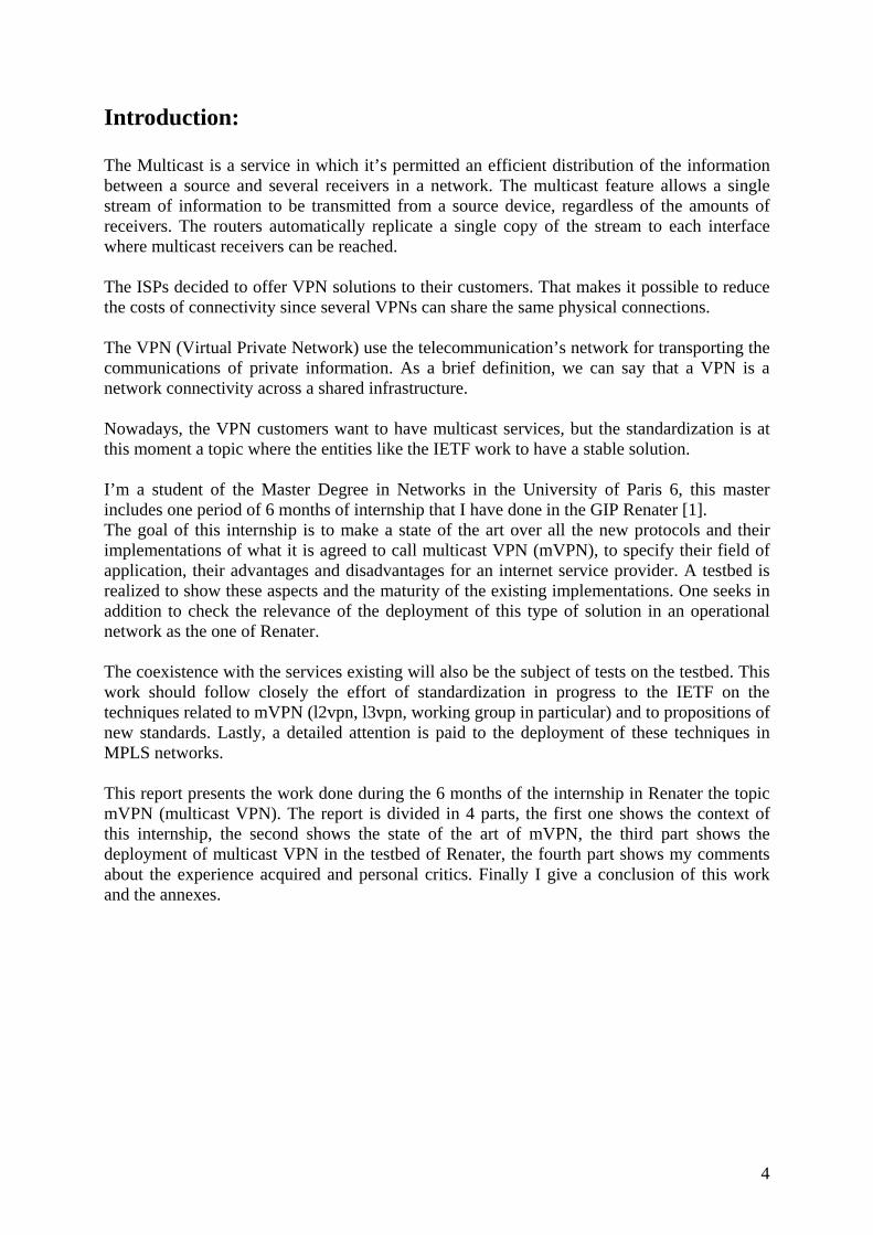
Nowadays, more than 600 French establishments having an activity in the fields of Research, Technology, Teaching and the Culture are connected to RENATER. This network enables them to communicate among the research entities. The Renater’s Network is composed of a national backbone and international connections with high bandwidth. RENATER is also present in the departments and overseas dominions. The third generation of the network is called RENATER-3. which uses optical technologies of multiplexing (DWDM), and the speed in the backbone is of 2.5 Gbits/s. The architecture of RENATER-3 is shown in figure 1.1.1
5
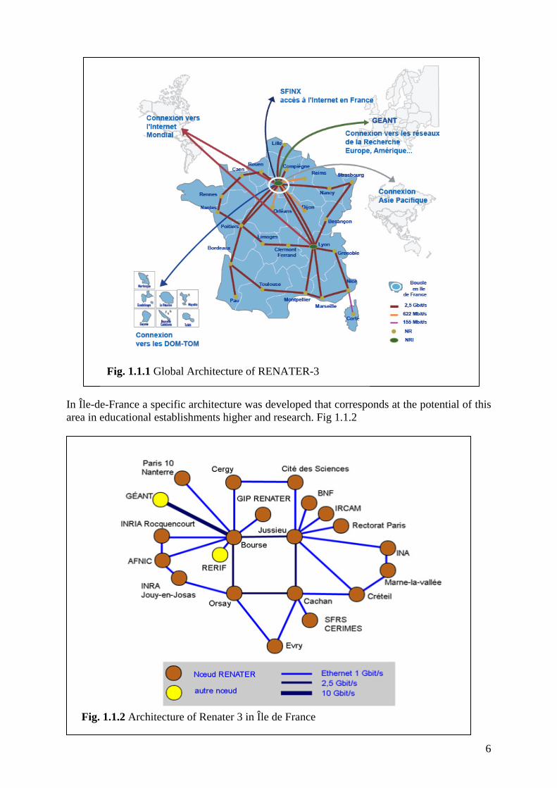
Fig. 1.1.1 Global Architecture of RENATER-3
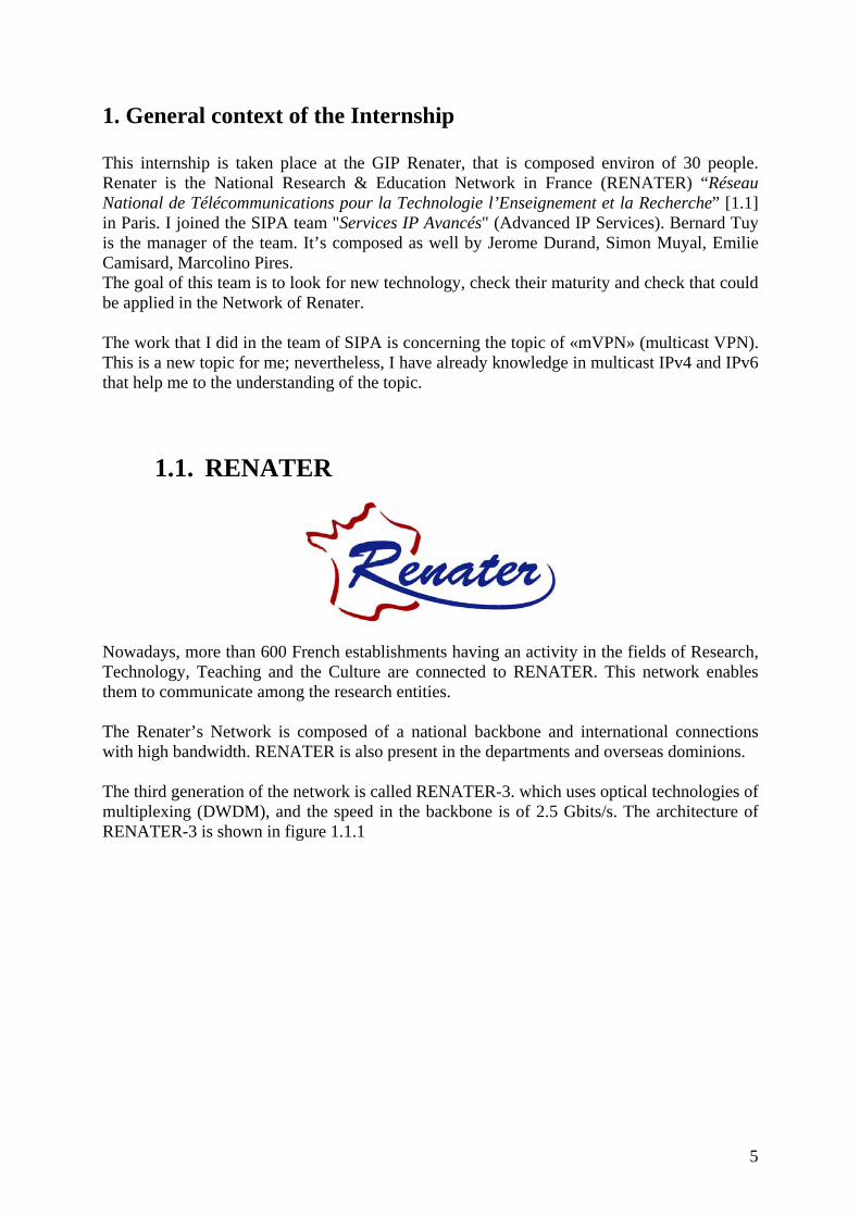
In Île-de-France a specific architecture was developed that corresponds at the potential of this area in educational establishments higher and research. Fig 1.1.2
Fig. 1.1.2 Architecture of Renater 3 in Île de France
6

Connections whit other R&E networks in the world. RENATER is inter-connected to 10 Gbit/s with the other European and American networks of research - including the Internet 2 (network ABILENE) - via the GEANT European network which is, at the world level, the greatest structure of this type. A connection with 155 Mbit/s leading in Korea ensures the communication with the networks of the research of the zone Asia-Pacific.
Connections with the Internet In France the communication with the Internet is carried out by the node of exchange SFINX (link of 3*1 Gbit/s with more than 80 operators) that is managed by RENATER. The communication with the Internet in the rest of the world is ensured by the connection of RENATER to the backbone to 5 Gbit/s in the backbone OpenTransit France Telecom. Among the services, RENATER offers: the protocols IPv4 and IPv6 (new generation of the Internet), IPv4 multicast, it’s used mainly for the videoconferences, the management of the quality of service (QoS), and the security which is ensured by the CERT-RENATER. To produce these services the GIP-RENATER develops technologies such as metrology and maintains relations followed with its users. The department of SIPA has a testbed where the new technologies are tested for checking their maturity. As an example, there are currently tests of IPv6 multicast and MPLS. When I joined to RENATER, after the first month, it was inaugurated the fourth generation of the Network that is called RENATER 4. Main changes are:
• Reinforced grid of the network for a better availability (suppression of pendular links)
• Introduction of a more "intelligent" routing to optimize the use of the network ("traffic engineering") and to reduce time convergence in the case of breakdown or of maintenance in a connection
• Infrastructure of connections of the type "black fibres" to transport large projects, and thus deployment of equipment WDM (DWDM) in the "shelters" of the operators and in the POP (Points of Presence).
The services already available in RENATER-3 stay in the new version of the backbone:
• IPv4 & IPv6 unicast • IPv4 Multicast • VPN services : MPLS-VPN of level 2 and 3, service of EoMPLS
The pilot services in RENATER-3 will be deployed as services in RENATER-4:
• IPv6 Multicast (M6BONE Network [4]) • Classes de services (CoS) • LBE (Less than Best Effort) • BE (Best Effort) • BBE (Better than Best Effort) • IP Premium
7
• Class supervision/control (reserved)
Fig. 1.1.3 Architecture of RENATER-3 vs Architecture of RENATER-4
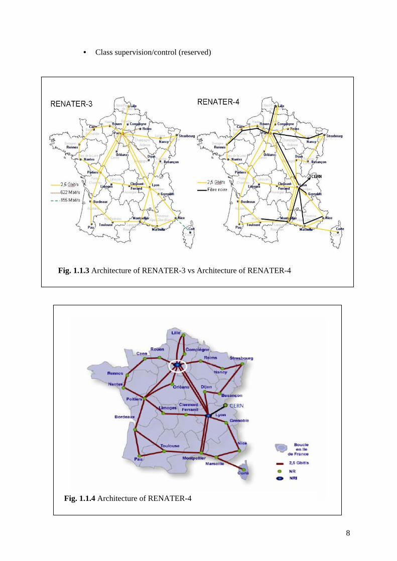
Fig. 1.1.4 Architecture of RENATER-4
8

1.2. IETF [2]
The IETF is the “Internet Engineering Task Force” that is composed of designers, operators, and people that do the research concerning the Internet architecture. This task Force is open to any interested individual. This IETF has different topics that are discussed in different working groups that are of the interest of the community of the internet, these topics are discussed mainly in mailing lists and in meetings that are leading 3 times per year. I realized that there were some working groups that have a direct relation to the works related to mVPN. Those groups are L2vpn, L3vpn and the PIM group where I describe the interest of my part to join this working group in the sections 1.2.1, 1.2.2, and 1.2.3.
1.2.1. L2vpn-WG This working group (wg) has as a mission to specify solutions to be supported in a provider-provisioned L2 VPN. In this working group there is some approach of the topic of multicast VPN, but at this time, the propositions are starting to be discussed in this working group. I follow the discussions in this working group, as the Internet Drafts that are submitted are discussed in the mailing list.
1.2.2. L3vpn-WG The L3vpn working group has the mission of specifying solutions to support in a provider-provisioned L3vpn. The topics that are discussed at this time are based on the RFC 2547, as the aspects of IPv6 (Internet Protocol version 6) and multicast in VPNs. The topic of multicast VPN is mainly discussed in this working group, so I have been more interested in the discussions of this working group.
1.2.3. PIM-WG The Protocol Independent Multicast (PIM) working group has been created to discuss and promote the PIM v2 Sparse Mode (SM) ands Dense Mode (DM) as scalable and efficient multicast routing protocol. I follow the discussion of this working group because there are aspects like make modifications to PIM to use it for the implementation of mVPN.
9

2. mVPN State of the art In order to know the works that have started concerning mVPN, I decided to make a state of the art to knowk all the solutions proposed and their status, so we can know the maturity of every solution that could be implemented in a production network.
2.1 What is mVPN ? [23] mVPN makes reference to “multicast VPN”, it indicates a VPN in which, the VPN client have the multicast service. Now, with the works that have been done, so for the new definition is that a mVPN is a solution that allows to perform the multicast service in a Layer 3 provisioned VPN.
2.2 Why mVPN? Nowadays, the customers for multicast services, for example for:
- Videoconference - E-Learning - Applications based in Multicast
As the customers are connected through VPN’s, ISP’s need to offer multicast in VPN’s, so they have to offer a solution that solves the necessity of the client in an efficient way. The applicability of mVPN is to provide a solution that allows an entity to have the service of multicast in a private way, for those entities that are connected through a VPN, according to the architecture that is described in the IETF Internet Draft “BGP/MPLS IP VPNs” [32]. In this way, the customer doesn’t do the work of providing the multicast service; it’s the ISP that is going to be the responsible.
10

2.3 mVPN requirements [28] These requirements are based in the IETF draft “draft-ietf-l3vpn-ppvpn-mcast-reqts-01”. The requirements shows what is needed to implement multicast VPN in L3 provider networks. Those requirements are oriented to the end user and the Service Provider (SP). In order to provide the multicast private service in an efficient way, new mechanisms must be implemented to support it. The solution implemented has to be compatible with the Internet Draft “BGP/MPLS IP VPNs” [32], in this draft, the multicast is not taken into account. The solution should ensure that the multicast traffic of the client is not lost nor duplicated, and concerning the architecture, the security aspect has to be the same as for the unicast and the multicast. The multicast private service doesn’t need to have extra features in CE (Customer Edge), as the unicast solution. Another important aspect is the scalability; the solution must to take into account the number of equipment in the core of the Service Provider and the number of equipments in the Customer side. In a summary way, this draft has aspects as : RP engineering, Carrier’s Carrier model in a scalable and efficient way, Security, QoS. I think that the IPv6 aspects must be taken into account, address range, and protocols required, that is going to help to the solutions that are proposed, there is a proposition concerning IPv6, at this time, only the unicast is taken into account according with the Internet Draft “RFC 2547bis” that is the ietf draft “BGP-MPLS IP VPN extension for IPv6 VPN” [31]. This draft is based on RFC 4031 [21], where the ISP only takes into account layer 3 VPN’s.
11

2.4 Propositions for mVPN 2.4.1 Tunneling among CE’s [27] This solution is referenced in the IETF draft “draft-rosen-vpn-mcast-03.txt” that proposes a solution for providing the multicast service. In the soultion proposed, it’s the customer that makes all the work for the implementation, the ISP only forwards the unicast traffic of the customer, and the ISP doesn’t have any control of it. The Internet Drat “draft-ietf-l3vpn-rfc2547bis-03” (BGP/MPLS IP VPNs) [32] describes a method for providing a VPN service. It specifies the protocols and procedures which must be implemented in order for a Service Provider to provide a unicast VPN. This solution extends that specification by describing the protocols and procedures which a Service Provider must implement in order to support multicast traffic in a VPN, assuming that PIM (Protocol Independent Multicast) is the multicast routing protocol used within the VPN, and the SP network can provide PIM as well. This solution that was taken is to make tunnels between the CE (Customer Edge), as shown on Figure 2.4.1.1. This solution was abandoned because it’s not scalable for the following reasons: - Point to point tunnels removes the benefits of multicast - The traffic has to be replicated by the CE router for each remote CE router - The customer has to manage the private multicast service - Configuration complexity and overhead for the customer - Service Provider cannot control the service as it is hidden in tunnels
Fig. 2.4.1.1 Unicast Tunnel to provide the private multicast service
12

2.4.2 “Multicast Domain” by Cisco Systems [28] This mVPN solution is based on the Internet draft (draft-rosen-vpn-mcast-08.txt). In the previous solution 2.4.1, is the customer that looks for having a solution to have the private multicast service. In this solution of Multicast Domain, the Service Provider is in charge to offer the solution to the customer. One of the problems that the Service Provider realized is that, if they would like to offer the native private multicast service to their customers, there will be an amount of PIM-Instances and multicast distribution information [(S,G), (*,G) states] to be maintained in the Core of the network. This solution is based in an architecture that is in the Internet Draft RFC-2547bis [32], but in this draft, the multicast service is not taken into account. The solution of “multicast domain” consist in establishing tunnels among the PE’s, using as the tunnel destination a multicast address to connect all the PE routers that have a site that belongs to the same VPN. To achieve this, it’s necessary to enable PIM in the core of the Network, so it can extend the multicast service to another customers that are connect between PE routers. This type of tunnels are considered as Point to Multipoint Protocol
1Note that the multicast address is assigned by the Service Provider and there is a different multicast group for every Multicast Domain (MD). In the network of the ISP is created what is called Default Multicast Distribution Tree (Default-MDT). It’s formed by P and PE routers of the Service Provider that are used to construct the path to bypass the control messages, this tree is constructed by PIM-SM mechanisms. This Default-MDT is showed in the figure 2.4.1
Fig. 2.4.2.1 Default-MDT in the Service Provider
A Multicast Domain is a set of VRFs instances that are multicast enable. 1
13

The Default-MDT is always used to send multicast control traffic between PE routers in a multicast domain. The amount of the states in the core of the service provider depends in the number of VPNs that it connects, this reduces considerably the states, because there wont be a Default-MDT for every multicast group flow of the customer. When the Default-MDT is created, there is a multicast interface that is created to bypass the multicast traffic of the customer to the receivers, this is called Multicast Tunnel. It is then thorugh the Multicast Tunnel (MT) where the traffic is bypassed through this tunnel s showed in the figure 2.4.2.
Fig. 2.4.2.2 Multicast Tunnel between PEs to bypass the customer multicast traffic. In fact, there is a MTI (Multicast Tunnel Interface) that is the way to access to the multicast domain. This MTI appears in the mvrf (multicast vpn routing and forwarding) as an interface called Tunnelx, where x is the number of the tunnel. We can say that the MTI is a gateway that connects the customer side (mvrf) to the service provider side (MDT). There’s need of one MTI to access a multicast domain and forward the customer traffic. The MTI is created dinamically upon the configuration of the Default-MDT.
14

At the beginning it seams a good solution, because the customers can extend the private multicast services to another site of the same VPN. But what they realized after is that there were PE routers that receive the multicast traffic where there were no receivers. This is a problem because it’s not optimal for the Serivce Provider, due that, it spends a lot of CPU processing and bandwidth, this is showed in the figure 2.4.2.3 where the customer of the site A1 of the VPN “blue” that is connected thorough PE-1 sends to different sites of the same VPN “blue”. In this case only PE-3 has a receivers that are the site A3 and A4. The customer A2 has no receivers, but it receives the multicast traffic anyway.
Fig. 2.4.2.3 PE-2 spends CPU processing and bandwidth for no receivers in A-2 To solves the waste of CPU processing and bandwidth, there is another MDT type that is called “Data-MDT”. This Data-MDT is used to bypass high traffic from one source to only PEs that have receivers for that flow. The Data-MDT is created dinamically when the multicast traffic of the customer exceeds a bandwidth threshold. For every VRf there’s need of a rank of addresses to be allocated to the Data-MDT. This Data-MDT work as follow: First, the PE that connnect the customer that is the source realizes that the flow exceeds a treshold determined by the Service Provider. The source PE is going to send a new join message called “MDT join TLV”. This messge is going to be sent through the Default-MDT with a User Datagram Protocol (UDP) type-length-vector (TLV), the MDT TLV join describes with another multicast address that is going to be the address that describes the source and group (S,G) that is actually working in the VRF instance and the new data MDT group address used in the provider space.
15

All the PE routers of that multicast group are going to receive the “MDT join TLV” because it is sended through the Default-MDT. The PE with receivers are the only routers that can join to the new group that is sent by the new MDT by the source PE. The PE routers that don’t have receivers ignore the MDT TLV join. When the PE routers have joined to the new group, the remote PEs send a PIM join message to be added in the new group of the Service Provider. The source PE encapsule the customer multicast traffic using the new Data-MDT after 3 seconds, this time allow to the PE routers to switch to the new group. The creation of Data-MDTs depends on the monitoring of the multicast source data rate. At this time, this internet draft has no new modifications because the work has stopped because there is an approach that is explained in section 2.4.6
16

2.4.3 “Multicast VPN and VPLS by Juniper Networks” [25] This draft proposes a solution to overcome the limitations of existing multicast VPN and multicast VPLS solutions. It gives procedures to enhance the scalability of multicast for BGP/MPLS VPNs. The solution proposes the utilisation of the protocol BGP to discover and maintaining PIM neighbors in a given mVPN. This solutions aims to overcome the limitations of IP multicast in VPLS with existing solutions. The limitations of current VPLS proposals for VPLS Multicast are that; It doesn’t allow using P-Multicast Trees for VPLS multicast data traffic. The Pes with VPLS sites that do not have receivers in a given multicast customer receive traffic for that flow. There’s no use of PIM peering between CE’s and PEs and there’s no PIM peering amon Pes. At this time, this internet draft has expired and there are no updates.
17

2.4.4 “Solution by Yasukawa” by NTT Corporation [26] In this solution proposes procedures to establish optimal virtual private IP Multicast in a Service Provider network in dividing the multicast of the customer in several regions. The solution propose to minimize the PIM neighbor maintenance to the remote PEs. As a result, the solution can construct IP multicast distribution trees that have optimal topologies for IP multicast distribution and avoid using multiple multicast and unicast distribution tunnels in the service provider core during the customer's tree transition phase. This simple multicast tunnel operation mechanism within a core provides easy and flexible IP multicast VPN service operation for the service provider. And, because the solution can terminate each customer's Join/Prune message at PEs, the solution can minimize PIM neighbor maintenance over remote PEs. This enhances the scalability performance of multicast VPN service network. This document also describes a P2MP TE LSP based multicast tunnel mechanism which could enhance TE capability and reliability of IP multicast VPNs. This work is stopped because, the authors has joined the work that are doing in the Internet Draft RFC-2547bis [25].
18

2.4.5 “Multicast in VPLS” by Juniper Networks [24] The Virtual Private LAN Services (VPLS) allows service providers to deliver VPN services based on Ethernet with the same level of support and reliability as existing services such as Frame Relay and ATM. This draft describes procedures for VPLS (Virtual Private LAN Service) multicast that utilize multicast trees in the sevice provider (SP) network. One such multicast tree can be shared between multiple VPLS instances. Procedures for propagating multicast control information, learned from local VPLS sites, to remote VPLS sites, are described. These procedures do not require IGMP-PIM snooping on the SP backbone links. This is a reasonable model when the bandwidth of the multicast traffic is low or/and the number of replications performed on an average on each outgoing interface for a particular customer VPLS multicast packet is small. If this is not the case it is desirable to utilize multicast trees in the SP core to transmit VPLS multicast packets. Note that unicast packets that are flooded to each of the egress PEs, before the ingress PE performs learning for those unicast packets, will still use ingress replication.
19

2.4.6 “Based “I-D 2547bis” by Cisco Systems and Juniper Networks” [29] This draft presents a new model that involves the enterprises Cisco Systems and Juniper Networks, the thing is that the solutions proposed have different topologies, it means that Juniper proposes use BGP to the construction of MDT and Cisco propose use PIM mechanisms to achieve this. What it happened is that they have proposed a solution where there are new terms. They have called this P-MSI that means Provider Multicast Service Interface which there are three types: The first one allow the communication of all with all, the second one allows the communication from all to some, and the last one can transmit from some to some, where it provides a major options that the models related, note that this is a work that has not been implemented yet. Several types of tunnels can be used (MPLS, GRE, etc) for the encapsulation. To my point of view, there are some aspects that need to be clarified.
20
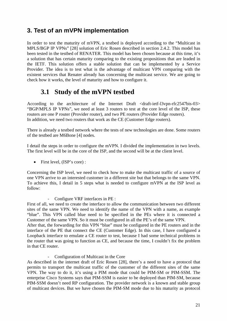
3. Test of an mVPN implementation In order to test the maturity of mVPN, a testbed is deployed according to the “Multicast in MPLS/BGP IP VPNs” [28] solution of Eric Rosen described in section 2.4.2. This model has been tested in the testbed of RENATER. This model has been chosen because at this time, it’s a solution that has certain maturity comparing to the existing propositions that are leaded in the IETF. This solution offers a stable solution that can be implemented by a Service Provider. The idea is to test what is the advantage of multicast VPN comparing with the existent services that Renater already has concerning the multicast service. We are going to check how it works, the level of maturity and how to configure it.
3.1 Study of the mVPN testbed According to the architecture of the Internet Draft <draft-ietf-l3vpn-rfc2547bis-03> “BGP/MPLS IP VPNs”, we need at least 3 routers to test at the core level of the ISP, these routers are one P router (Provider router), and two PE routers (Provider Edge routers). In addition, we need two routers that work as the CE (Customer Edge routers). There is already a testbed network where the tests of new technologies are done. Some routers of the testbed are M6Bone [4] nodes. I detail the steps in order to configure the mVPN. I divided the implementation in two levels. The first level will be in the core of the ISP, and the second will be at the client level.
• First level, (ISP’s core) :
Concerning the ISP level, we need to check how to make the multicast traffic of a source of one VPN arrive to an interested customer in a different site but that belongs to the same VPN. To achieve this, I detail in 5 steps what is needed to configure mVPN at the ISP level as follow:
- Configure VRF interfaces in PE : First of all, we need to create the interface to allow the communication between two different sites of the same VPN. We need to identify the name of the VPN with a name, as example “blue”. This VPN called blue need to be specified in the PEs where it is connected a Customer of the same VPN. So it must be configured in all the PE’s of the same VPN. After that, the forwarding for this VPN “blue” must be configured in the PE routers and in the interface of the PE that connect the CE (Customer Edge). In this case, I have configured a Loopback interface to emulate a CE router to test, because I had some technical problems in the router that was going to function as CE, and because the time, I couldn’t fix the problem in that CE router.
- Configuration of Multicast in the Core As described in the internet draft of Eric Rosen [28], there’s a need to have a protocol that permits to transport the multicast traffic of the customer of the different sites of the same VPN. The way to do it, it’s using a PIM mode that could be PIM-SM or PIM-SSM. The enterprise Cisco Systems says that PIM-SSM is easier to be deployed than PIM-SM, because PIM-SSM doesn’t need RP configuration. The provider network is a known and stable group of multicast devices. But we have chosen the PIM-SM mode due to his maturity as protocol
21
and to test how it works and how the PIM messages are treated. So an RP is implemented in the core of the testbed network. Using PIM-SM v2 it’s possible to bypass the control messages and data plane of the clients of the different sites that belongs to the same VPN through what is called Default-MDT that is configured statically in all the PEs with the same multicast address taking into account the P routers of the Service Provider.
- Configure the Provider Network for PIM-SM The destination addresses of the tunnels are multicast addresses, they are used to create the multicast distribution trees in the core of the network, we need a protocol that permits to bypass the multicast traffic of the client through the Service Provider backbone, we need a multicast protocol that administrate the trees that are created, so PIM-SMv2 [33] is the solution.
- Choose the VPN group addresses used in the Provider Network This is basically to assign the multicast addresses that are used to establish the MDT (Multicast Distribution Tree) in the Service Provider Network. The addresses are chosen from the RFC 2365 (Administratively Scoped IP Multicast) [11]. These addresses were taken because if the ISP provides the multicast service, we need be sure to not re-use the Provider group addresses that are used in the internet multicast. That’s why the RFC 2365 [11] is taken. The groups that I have chosen for the creation of the Default-MDT are in “239.192.0.0/16” IPv4 prefix.
- Configuration of Peer BGP. In order to exchange the prefixes of the different sites of the same VPN, it’s needed to establish a session called “session de iBGP” between the PEs. In the case that a PE connects 2 different sites of different VPNs, that has the same prefix, the distinction can be done thanks to the RD (Route Distinguisher). It allows separating and identifying the prefix of every site without send it to an erroneous site. The configurations can be checked in section 6.6.
• Second level, (Customer) : When we want to integrate the Customer level, there are no big changes to be done in the multicast configuration that the customer already has, due that the ISP makes the work to connect the different sites. I detail in 3 steps for implementing multicast VPN in the customer side:
- Enable the multicast routing in the router. - Enable the interfaces PE-CE for sparse-dense mode, which make sure that
either “auto-rp” or “bsr” messages are received and forwarded allowing the PE to learn the group to rp inside the vpn.
- The PIM sparse-dense mode is the multicast routing protocol
22

3.2 Implementation of mVPN in the Renater’s testbed
In order to implement the mvpn, some changes needed to be done in this network. The testbed consists of 5 routers, which are placed as follow: The first equipment will work as PE in the testbed and will be called PE-1 (gsr-6net). The second equipment will work as P in the testbed and will be called gsr-nio. The third equipment will work as PE in the testbed and will be called PE-2 (7200-MCAST). In the three first routers, we have the architecture for the Core of the network, so the other 2 equipments in the testbed work as the Customer Edge (CE). The fourth equipment will work as CE in the testbed and will be called CE-1 (7200-MPLS). The fifth equipment will work as CE in the testbed and will be called CE-2 (FM6BONE). Unfortunately, as I explain in section 3.1, I couldn’t test the second level that is the customer tests due to a problem in the router 7200-MPLS that has a problem in the interface ATM. Because the time, I couldn’t fix the problem in this router, nevertheless, I did something else. I configured one logical interface of loopback in every PE in the router “gsr-6net” and the router “7200-MCAST” to emulate the interface that acts as a CE. It allows me to exchange the prefixes between the PEs. After a brief description of the routers, the testbed is showed as follows in the fig 3.2.1.
Fig. 3.2.1 Testbed network topology for mVPN
23

According to the study done in section 3.2, I detail the steps done for the implementation of mVPNs. In this testbed, the implementation was divided in two steps. First step is the configuration of the core of the network, taking in account the P and PE routers. The second step is the configuration of the Customers part, which in this case are the CE-1 and CE-2 routers. The links of this testbed are OC-3 ATM (155 Mbps). The configuration of routers is detailed in section 6.6. In this section I describe the steps and procedures that I had to do in order to implement the multicast vpn in the core of the testbed. The router used as an example is the GSR-6NET (PE-1). As shown in figure 3.2.1, I created the sites VPN need in the PEs. A VRF (VPN Routing and Forwarding) must be configured for each VPN. These example VRF “blue”, Figure 3.2.2, shows how to configure it.
Fig. 3.2.2 Create the vrf blue.
The “rd” is used to distinguish the distinct VPN routes of separate customers who connect to the provider. It has only one purpose: to make IPv4 prefixes globally unique. The 8-byte route distinguisher consists of 3 fields: Type field (2 bytes) – determines the lengths of the other two fields, as well as the semantics of the administrator field. Administrator field – typically the 4-byte (AS) autonomous system number of the provider. Assigned Number field – assigned by the provider. The multicast routing in the router must be configured in the PE routers; this is done as follow in the figure 3.2.3:
Fig. 3.2.3 Configure the multicast routing After the vrf is created and the multicast is available, we configure the logical interfaces where the BGP peers are established between the PEs. PE routers are the only routers that need to be MVPN aware and able to signal to remote PE's information regarding the MVPN. That’s way it is fundamental that all PE routers have a BGP relationship with each other. The
24
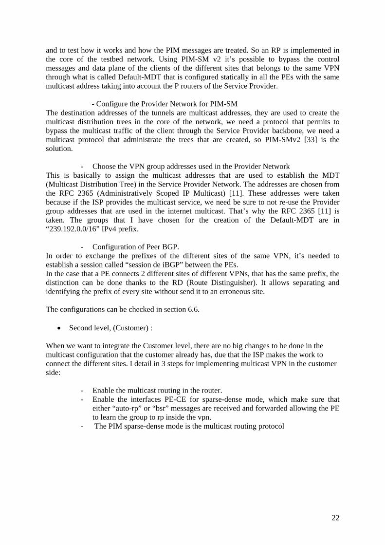
address of this interface is the “194.254.101.2” and the number of the Loop back is “0”, in this interface we have to qualify the interface of PIM, to create the MDT’s in the core of the network, these steps are showed in figure 3.2.4.
Fig. 3.2.4 Create the interface loopback for peerings
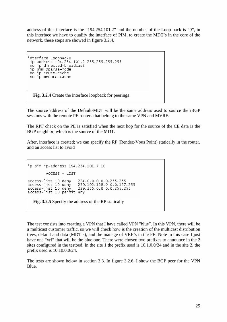
The source address of the Default-MDT will be the same address used to source the iBGP sessions with the remote PE routers that belong to the same VPN and MVRF. The RPF check on the PE is satisfied when the next hop for the source of the CE data is the BGP neighbor, which is the source of the MDT. After, interface is created; we can specify the RP (Rendez-Vous Point) statically in the router, and an access list to avoid
Fig. 3.2.5 Specify the address of the RP statically
The test consists into creating a VPN that I have called VPN "blue”. In this VPN, there will be a multicast customer traffic, so we will check how is the creation of the multicast distribution trees, default and data (MDT’s), and the manage of VRF’s in the PE. Note in this case I just have one “vrf” that will be the blue one. There were chosen two prefixes to announce in the 2 sites configured in the testbed. In the site 1 the prefix used is 10.1.0.0/24 and in the site 2, the prefix used is 10.10.0.0/24. The tests are shown below in section 3.3. In figure 3.2.6, I show the BGP peer for the VPN Blue.
25

Fig. 3.2.6 Configuration of the BGP peering of the VPN blue
3.3 Test of the functionality of mVPN In this section all the tests are shown. First I’ll show the tests done in the core of the network and after I’ll present the tests for the customers. Note that the configuration of the routers are in section 6.6. In the figure 3.3.1, I show the iBGP peer established among the PE-1 and the PE-2. The AS (Autonomous System) number used is the one of the Renater’s testbed “1717”. The address of PE-1 used to establish the peer is 194.254.101.2, and the address of PE-2 is “194.254.101.3”. The figure 3.3.1 was taken from the gsr-6net equipment, as you can see; there is an exchange of prefixes between the PE-1 and the PE-2 in the VPNv4 Unicast address family. To show this information the command “sh ip bgp neighbors 194.254.101.3” is used.
26

Fig. 3.3.1 Peering established among the PE-1 and the PE-2
27

After the peering is established, I show in the figure 3.3.2 the exchange of prefixes of the VPN blue. They are announced by an logical interface, this is done with the command “sh ip bgp vpnv4 vrf blue”, and in this case the “gsr-6net” equipment has the prefix of the 2 sites. As in CE were not disponibles, the thing that I did is to configure an interface logic
Fig. 3.3.2 It shows the prefix announced of the PE-2
Now, I describe the tests of the creation of the MDT (Multicast Distribution Tree). In this step the configuration is done statically as shown in section 6.6. I decided to use the multicast address 239.192.10.1 for the creation of the Default-MDT, and the multicast address 239.192.10.2 for the Data MDT. In the figure 3.3.3 is displayed the multicast address for the Default-MDT.
Fig. 3.3.3 It shows the multicast address of the Default-MDT
When the Default-MDT is configured, there is a Tunnel that is created automatically that is called the Multicast Tunnel “MT”. The multicast traffic of the customer is going to be transported through the core of the ISP in the tunnel. This interface is showed in the Fig 3.3.4, the number of the interface is assigned automatically. In this case the number of the interface is the number 4. The command to display this interface and the status in a router is “sh ip igmp vrf blue interface tunnel 4”.
28

Fig. 3.3.4 The multicast tunnel is created automatically
As shown in the fig. 3.3.5, the PE is going to function like the DR (Designated Router) that is going to send the IGMP and Hellos messages.
Fig. 3.3.5 The PE works as the DR (Designated Router).
In order to verify the group of the Default-MDT is running and the status, we can verify with the command “sh ip pim rp 239.192.10.1” as showed in the fig 3.3.6.
Fig. 3.3.6 Status of the multicast group of the Default-MDT
29

In the previous example, we have checked the status for a specific group, but in fact we can check the list of groups that are actives and the time that has been up. In the fig. 3.3.7 are shown the groups that are in use. We can see in addition of the previous example the address 224.0.1.40, that is reserved by IANA, this multicast address serves for the “cisco-rp-discovery”.
Fig. 3.3.7 Status of the multicast groups of the PE
To display the contents of the multicast trees and states, use the command “show ip mroute” command, it displays the all groups and sources as shown in fig 3.3.8.
Fig. 3.3.8 This figure shows the multicast trees and states
30

There are new state flags for (*,G) / (S,G) Entries as shown in fig. 3.3.8 : “Z”, Multicast Tunnel : Signifies the (*, G) (S, G) entry in the global table is an MDT and local PE has a matching MDT group associated with mVRF. If Z is set, then arriving packets must be decapsulated to reveal customer multicast packet. “Y”, Joined Data-MDT : Signifies traffic for (S, G) entry in mVRF is received from data-MDT. “y”, Sending to Data-MDT : Signifies traffic for (S, G) entry in mVRF is transmitted to Data-MDT.
3.4 Experience feedback During the implementation, I have experienced that there are not big requirements concerning the equipment, in the core of the network. We only need a technology that is very well tested as the multicast, in order to transport the multicast traffic of the clients in a private way. The PE is the router that has more activity concerning the process of CPU for the mVPN. When the PE receives traffic where it doesn’t have customers to join it, there’s a The problem in PE routers is the consummation of CPU, due to the process usefulness of multicast traffic when there are no receivers. There’s no need to change anything in the customer network to implement the multicast VPN, which is going to help to the deployment in a network. At this time, there is a draft for requirements in multicast VPN and several drafts propositions concerning multicast VPN at the IETF [2], there’s no a solution that is a RFC, but works are still in progress. I think that it should be specified in a clearly way what is a must and what is not in the implementation.
31

4. Discussions and prospects
4.1 Study for the implementation of MVPN in RENATER’s Network
A Multicast-VPN allows an entity to transparently interconnect its private network across the network backbone of a service provider. The use of a Multicast-VPN to interconnect a network in this way does not change the way that network is administered. If we take the solution of Eric Rosen [28], we have to check that in the Renater’s Network, there are routers that act as a PE and P at the same time, du that some routers in the core are used to connect other sites, so they have the function of P and PE in the network. There wouldn’t be a problem for making the implementation in the Network of Renater, in order to have a scalable multicast solution, the amount of states maintained by the P routers should be proportional to be under control, so this solution at least, the amount of states maintained in the P routers is proportional only to the number of VPNs which run over the backbone, the amount of the states in the P (Provider routers) routers is not sensitive to the number of multicast groups or to the number of multicast transmitters within the VPN. In this solution, the optimality of the multicast routes is reduced to have a good and acceptable scalability. The SP however has control over the tradeoffs between optimal routing and scalability. The mVPN can serve to those entities that are connected through a VPN that internally has the multicast service and that want to extend it to another site, so the entities that Renater connect through a VPN can have the multicast service. There are several aspects that have to keep in mind for a good implementation as the encapsulation that could be “IPinIP”, “GRE”, or “MPLS”, that only works for the transport of the multicast traffic of the client.
32

4.2 Coexistence between existing multicast services with mVPN
The Network of Renater offers already the multicast service for IPv4. Very soon it will offer multicast IPv6 (January 2006). The goal of this work is to have a vision of what the multicast VPN can offer comparing with the existing services that are already deployed in Renater, as showed in the tests done, we can say that the multicast service in IPv4 in a VPN can be offered, having the coexistence with the multicast services already deployed in Renater. The multicast VPN can serve to the sites connected through a VPN that want to extend this service to other sites.
33

5. Conclusions We can conclure this work with good experiences about the multicast VPN, in this work I have done a state of the art of the works related to mVPN, but the works are still in progress, so as showed in the report, the solution that is taken that at this time is the one that present a major level of maturity comparing to the other propositions at the IETF.
34

6. Annexes
6.1 PN vs. VPN Until fairly recently, this has meant the use of leased lines to maintain a wide area network (WAN). Leased lines, ranging from ISDN (integrated Services Digital Network, 128 Kbps) to OC3 (Optical Carrier-3, 155 Mbps) fiber, provided a company with a way to expand its private network beyond its immediate geographic area. A WAN had obvious advantages over a public network like the Internet when it came to reliability, performance and security. But maintaining a WAN, particularly when using leased lines, can become quite expensive and often rises in cost as the distance between the offices increases. In the other hand we have the VPN is a secure network connectivity across a shared infrastructure. The VPN sends data over the network through "tunnels". An academic definition of a VPN is “connectivity deployed on a shared infrastructure with the same policies and performance as a private network, with lower total cost of ownership.”
Fig. 6.1.1 show the difference of the PN and a VPN
6.1.1 Types of VPNs Increasingly challenged to offer much more than just basic connectivity and Internet access, service providers must address key business concerns of today’s enterprises to attract and keep customers. VPNs are designed based on one of two architectural options—client-initiated or network access server (NAS)-initiated VPNs.
35

Client-initiated VPNs: Users establish a tunnel across the Internet service provider (ISP) shared network to the customer network. The customer manages the client software that initiates the tunnel. The main advantage of client-initiated VPNs is that they secure the connection between the client and ISP. However, client-initiated VPNs are not as scalable and are more complex than NAS-initiated VPNs. NAS-initiated VPNs: Users dial in to the ISP NAS, which establishes a tunnel to the private network. Network access server (NAS)-initiated VPNs are more robust than client-initiated VPNs and do not require the client to maintain the tunnel-creating software. NAS-initiated VPNs do not encrypt the connection between the client and the ISP, but this is not a concern for most customers because the Public Switched Telephone Network (PSTN) is much more secure than the Internet. VPNs can also run from a remote client PC or remote office router across the Internet or an IP service provider network to one or more corporate gateway routers. VPNs between a company’s offices are a company intranet. VPNs to external business partners are extranets.
6.2 Tunneling Tunneling is the transmission of data intended for use only within a private, usually corporate network through a public network. Tunneling is generally done by encapsulating the private network data and protocol information within the public network transmission units so that the private network protocol information appears to the public network as data. Tunneling allows the use of the Internet, which is a public network, to convey data on behalf of a private network.
6.2.1 GRE (Generic Routing Encapsulation) GRE is a tunneling protocol that was originally developed by Cisco that can encapsulate a wide variety of protocol packet types inside IP tunnels, creating a virtual point-to-point link to Cisco routers at remote points over an IP internetwork.
6.2.2 PPTP (Point to Point Tunneling Protocol) PPTP is a protocol that allows corporations to extend their own corporate network through private "tunnels" over the public Internet. Effectively, a corporation uses a wide-area network as a single large local area network. A company no longer needs to lease its own lines for wide-area communication but can securely use the public networks. This kind of interconnection is known as a virtual private network (VPN).
6.2.3 P2MP (Point to Multipoint Protocol) Point-to-Multipoint (p2mp) is a method of communication between a series of receivers and transmitters to a central location. P2MP typically is set up in three segments to enable frequency re-use.
36

6.2.4 Multicast Tunnel The MT (Multicast Tunnel) is a tunnel that is created dynamically and is used to transport multicast traffic of their customer through the backbone of the Service Provider. The Multicast Tunnel is used to create the MDT (Multicast Distribution Tree) in the core of the Service Provider.
6.3 Bibliography 6.3.1 Web pages
[1] http://www.renater.fr [2] http://www.ietf.org [3] http://www.cisco.com [4] http://www.m6bone.net
6.3.2 RFCs [5] 2637, PPTP (Point to Point Tunneling Protocol) http://www.ietf.org/rfc/rfc2637.txt?number=2637 [6] 2547, BGP/MPLS VPNs http://www.ietf.org/rfc/rfc2547.txt?number=2547 [7] 2770, GLOP Addressing in 233/8 http://www.ietf.org/rfc/rfc2770.txt?number=2770 [8] 2362, Protocol Independent Multicast-Sparse Mode (PIM-SM) http://www.ietf.org/rfc/rfc2362.txt?number=2362 [9] 2283, Multiprotocol Extensions for BGP-4 http://www.ietf.org/rfc/rfc2283.txt?number=2283 [10] Multicast Address Dynamic Client Allocation Protocol (MADCAP) http://www.ietf.org/rfc/rfc2730.txt?number=2730 [11] 2365, Administratively Scoped IP Multicast http://www.ietf.org/rfc/rfc2365.txt?number=2365 [12] 2784, Generic Routing Encapsulation (GRE) http://www.ietf.org/rfc/rfc2784.txt [13] 2974, Session Announcement Protocol http://www.ietf.org/rfc/rfc2974.txt?number=2974 [14] 2917, A Core MPLS IP VPN Architecture http://www.ietf.org/rfc/rfc2917.txt?number=2917 [15] 3031, Multiprotocol Label Switching Architecture http://www.ietf.org/rfc/rfc3031.txt?number=3031 [16] 3032, MPLS Label Stack Encoding http://www.ietf.org/rfc/rfc3032.txt?number=3032 [17] 3353, Overview of IP Multicast in a (MPLS) Environment http://www.ietf.org/rfc/rfc3353.txt?number=3353 [18] 2685, Virtual Private Networks Identifier http://www.ietf.org/rfc/rfc2685.txt?number=2685 [19] 3193, Securing L2TP using IPsec http://www.ietf.org/rfc/rfc3193.txt?number=3193 [20] 1483, Multiprotocol Encapsulation over ATM Adaptation Layer 5
37
http://www.ietf.org/rfc/rfc1483.txt?number=1483 [21] 4031, Service Requirements for Layer 3 (PPVPNs) http://www.ietf.org/rfc/rfc4031.txt?number=4031 [22] 4026, Provider Provisioned Virtual Private Network (VPN) Terminology http://www.ietf.org/rfc/rfc4026.txt?number=4026 [23] 2432, Terminology for IP Multicast Benchmarking http://www.ietf.org/rfc/rfc2432.txt?number=2432
6.3.3 Internet Drafts [24] Multicast in VPLS http://www.ietf.org/internet-drafts/draft-raggarwa-l2vpn-vpls-mcast-00.txt [25] Multicast in BGP/MPLS VPNs and VPLS http://vesuvio.ipv6.cselt.it/internet-drafts/draft-raggarwa-l3vpn-mvpn-vpls-mcast-01.txt [26] BGP/MPLS IP Multicast VPNs http://www.ietf.org/internet-drafts/draft-yasukawa-l3vpn-p2mp-mcast-01.txt [27] Multicast in MPLS/BGP IP VPNs http://www.watersprings.org/pub/id/draft-rosen-vpn-mcast-03.txt [28] Multicast in MPLS/BGP IP VPNs http://vesuvio.ipv6.cselt.it/internet-drafts/draft-rosen-vpn-mcast-08.txt [29] Multicast in MPLS/BGP IP VPNs http://www.ietf.org/internet-drafts/draft-ietf-l3vpn-2547bis-mcast-00.txt [30] Requirements for multicast in Provider Provisioned IP VPNs http://vesuvio.ipv6.cselt.it/internet-drafts/draft-morin-l3vpn-ppvpn-mcast-reqts-00.txt [31] BGP-MPLS IP VPN extension for IPv6 VPN http://www.ietf.org/internet-drafts/draft-ietf-l3vpn-bgp-ipv6-07.txt [32] BGP/MPLS IP VPNs http://mirror.switch.ch/ftp/mirror/internet-drafts/draft-ietf-l3vpn-rfc2547bis-03.txt [33] Protocol Independent Multicast – Sparse Mode version 2 (PIM-SMv2) http://tools.ietf.org/wg/pim/draft-ietf-pim-sm-v2-new/draft-ietf-pim-sm-v2-new-08.txt
6.3.4 Books [34] Developing IP Multicast Networks (Volume I), Beau Williamson Cisco Press
38

6.4 Glossary of terms CE Customer Edge CNI Customer Network Interface Data MDT Tree created dynamically to only interested PE routers of the same VPN Default MDT Tree created statically to connect ALL PE routers of the same VPN I-D Internet Draft ISP Internet Service Provider MD Multicast Domain MDT Multicast Distribution Tree MT Multicast Tunnel MTI Multicast Tunnel Interface MVPN Multicast VPN MVRF Multicast VRF P Provider Router PE Provider Edge Router PIM Protocol Independent Multicast PIM Bi-Dir Bi-directional PIM PIM-DM PIM-DM Dense Mode PIM-SM PIM-SM Sparse Mode PN Private Network PNI Provider Network Interface RP Rendezvous Point RPF Reverse Path Forwarding SP Service Provider VPN Virtual Private Network VRF VPN Routing and Forwarding WG Working Group
39

6.5 Equipment’s configuration For testing the multicast VPN, the equipments used are the following:
- 1 P - 2 PE
Configuration of equipment PE-1 (gsr-6net):
############################ PE-1 ############################ gsr-6net#sh run Building configuration... Current configuration : 11677 bytes ! upgrade fpd auto version 12.0 ! ! ip name-server 194.57.137.114 ip vrf blue rd 1717:1 route-target export 1717:1 route-target import 1717:1 mdt default 239.192.10.1 ! ip multicast-routing distributed ip multicast-routing vrf blue distributed ! ! interface Loopback0 ip address 194.254.101.2 255.255.255.255 no ip directed-broadcast ip pim sparse-mode no ip route-cache no ip mroute-cache ipv6 address 2001:660:3007:200:1::/64 ipv6 mtu 1480 ! interface Loopback9 description *** Tests MPLS *** ip vrf forwarding blue ip address 10.1.0.1 255.255.255.0 no ip directed-broadcast ! ! interface ATM6/0.1 point-to-point description -R-- GSR-NIO ---- ip unnumbered Loopback0 no ip directed-broadcast
40

ip pim sparse-mode ip router isis atm pvc 1003 0 1003 aal5snap no atm enable-ilmi-trap ipv6 address 2001:660:3007:12:2::/64 ipv6 router isis ! ! router isis net 49.0002.1930.5120.7240.00 metric-style wide passive-interface Loopback0 ! router bgp 1717 bgp router-id 194.254.101.2 bgp log-neighbor-changes neighbor 194.254.101.3 remote-as 1717 neighbor 194.254.101.3 update-source Loopback0 ! address-family ipv4 no neighbor 2001:660:3007:100:1:: activate no neighbor 2001:798:16:200::1 activate no neighbor 194.254.101.3 activate no auto-summary no synchronization exit-address-family ! address-family vpnv4 neighbor 194.254.101.3 activate neighbor 194.254.101.3 send-community extended exit-address-family ! ! address-family ipv4 vrf blue redistribute connected redistribute static no auto-summary no synchronization network 10.1.0.0 mask 255.255.0.0 exit-address-family ! ip pim rp-address 194.254.101.7 10 ! access-list 10 deny 224.0.0.0 0.0.255.255 access-list 10 deny 239.192.128.0 0.0.127.255 access-list 10 deny 239.255.0.0 0.0.255.255 access-list 10 permit any !
41

Configuration of equipment P (gsr-nio):
############################ P ############################ gsr-nio#sh run Building configuration... Current configuration : 11797 bytes ! version 12.0 ! ip multicast-routing distributed ! ! interface Loopback1 description ---- RP multicast IPv4 ---- ip address 194.254.101.7 255.255.255.255 no ip directed-broadcast ! ! interface ATM6/0.4 point-to-point description -R-- Lien vers GSR-6NET ---- ip unnumbered Loopback0 no ip directed-broadcast ip pim sparse-mode ip router isis atm pvc 1003 0 1003 aal5snap no atm enable-ilmi-trap sar vc 0 1003 txpool 0 ipv6 address 2001:660:3007:12:1::/64 ipv6 router isis ! interface ATM6/0.500 point-to-point description -R-- 7200-MCAST ---- ip address 194.254.101.13 255.255.255.252 no ip directed-broadcast ip pim sparse-mode ip router isis atm pvc 500 0 500 aal5snap no atm enable-ilmi-trap sar vc 0 500 txpool 0 ipv6 address 2001:660:3007:13:1::/64 ipv6 router isis ! router isis net 49.0002.1930.5120.7241.00 metric-style wide passive-interface ATM6/0.200 passive-interface Loopback0 passive-interface Loopback1
42

! router bgp 1717 bgp router-id 193.51.206.158 bgp cluster-id 3241398257 bgp log-neighbor-changes ! address-family ipv4 multicast neighbor 193.51.181.194 activate no auto-summary network 194.254.101.0 mask 255.255.255.192 exit-address-family ! ip pim rp-address 194.254.101.7 10 ! Configuration of equipment PE-2 (7200-MCAST):
############################ PE-2 ############################ 7200-MCAST#sh run Building configuration... Current configuration : 17072 bytes ! version 12.4 ! ip domain name projets.renater.fr ip name-server 194.57.137.114 no ip dhcp use vrf connected ! ! ip vrf blue rd 1717:1 route-target export 1717:1 route-target import 1717:1 mdt default 239.192.10.1 ! ip multicast-routing ip multicast-routing vrf blue ! ! interface Loopback0 ip address 194.254.101.3 255.255.255.255 ip pim sparse-mode ipv6 address 2001:660:3007:300:1::/64 ! ! interface Loopback9 description *** Tests MPLS ***
43

ip vrf forwarding blue ip address 10.10.0.1 255.255.255.0 ! ! interface ATM2/0.500 point-to-point description -R-- GSR-NIO ---- ip address 194.254.101.14 255.255.255.252 ip router isis ip pim sparse-mode atm pvc 500 0 500 aal5snap ipv6 address 2001:660:3007:13:3::/64 ipv6 flow ingress ipv6 router isis ! ! router isis net 49.0002.1930.5120.7242.00 metric-style wide passive-interface FastEthernet1/0 passive-interface Loopback0 ! ! router bgp 1717 bgp router-id 194.254.101.3 bgp log-neighbor-changes neighbor 194.254.101.2 remote-as 1717 neighbor 194.254.101.2 update-source Loopback0 ! ! address-family ipv4 no neighbor 194.254.101.2 activate no auto-summary no synchronization exit-address-family ! address-family vpnv4 neighbor 194.254.101.2 activate neighbor 194.254.101.2 send-community extended exit-address-family ! address-family ipv4 vrf blue redistribute connected redistribute static no auto-summary no synchronization exit-address-family ! ip pim rp-address 194.254.101.7 10 ! access-list 10 deny 224.0.0.0 0.0.255.255
44

access-list 10 deny 239.192.128.0 0.0.127.255 access-list 10 deny 239.255.0.0 0.0.255.255 access-list 10 permit any !
45