report of 4th pilot audit of transmission tower by the
TRANSCRIPT

1
Report of 4th Pilot audit of Transmission Tower by the audit team of the committee
for Audit of Transmission Tower
1. Background
In pursuance of Ministry of Power Letter No. 3/5/2017-Trans. Dated 07.08.2017, for the
audit of the transmission towers with respect to design and the life of the towers (on a 5%
sampling basis), the 4th pilot audit was carried out for the towers of the transmission lines
(tabulated below) on 16th ,17th & 18th January, 2019, wherein the following members
participated:
As transmission lines of Northern India & NCR region were already done in previous pilot
audits, so, Madhya Pradesh a central India location was chosen for better regional outlook.
The Audit members decided to audit both older lines and the newer line for holistic overview.
The older critical lines which were more than 29 years old were selected and for the new line,
a 3-year-old line was selected. Moreover, the members selected the towers in these lines for
auditing based on its locational criticality like Highway crossings, Railway crossings, river/canal
crossings, closeness to substation, accessibility, etc. The details of the audit of tower of
following lines with tower locational information are given below: -
SI no. Organization Name Designation (division)
1. PGCIL Shri Manoj Kumar Mittal Independent Director
Shri Abhishek General Manager
2. SERC-CSIR Shri R. P. Rokade Principal Scientist
3. CPRI Shri K Vijaya Kumar Enginnering Officer -Gr.III
4. CEA-CEI division Shri A.K. Thakur Director (CEI)
Shri I.K. Mehra Deputy Director (RIO- North)
Shri R.K. Meena Deputy Director (CEI)
Shri Mohit Mugdal Assistant Director (PSETD)
Shri Mukul Kumar Assistant Director (CEI)
2
2. Following tests/checks were conducted for tower audit: -
a. Visual inspection of the tower
The towers were inspected with the naked eye and with the use of binoculars for
missing members and bolts, buckling, etc. Danger plate which is for safety, number
plate, phase sequence markings which is for convenience and anti-climbing
arrangement/device which prevents un-authorized climbing on the tower were also
inspected.
Any missing force bearing members will cause uneven distribution of forces in the leg
and the capacity of the leg will be reduced which in turn harm the safety of the tower
& causes failure of towers/ cascading of failures if it is in the angle/section towers.
Any missing redundant members in the structure will cause uneven distribution of
forces in the force bearing members to which they are connected thus reducing the
SI no.
Name of
Transmission
line
Utility Audit date Year of
Commissioning Tower no. ( its location)
1
400 kV Seoni-
Sarni D/C
Transmission
Line
MPPTCL 16-01-2019 1984 a. 716 (Near canal)
b. 717 (Agricultural Field)
2
400 kV
Jabalpur-
Vindhayachal
D/C
Transmission
line
PGCIL 17-01-2019 1989
a. 984 (Railway crossing)
b.983(Agricultural Field)
c. 999 (Near road to
Village)
3.
765 kV
Jabalpur-Bina
D/C
transmission
line
Sterlite
Power
Transmission
Ltd.
18-01-2019 2016
a. 9 (Near Highway)
b. 10 (Near Highway)
c. 3 (Near Substation)
3
capacity of force bearing members. It will cause more stress in the members & may
leads to failure of towers even if the field/climatic conditions are normal for which the
line/towers are designed.
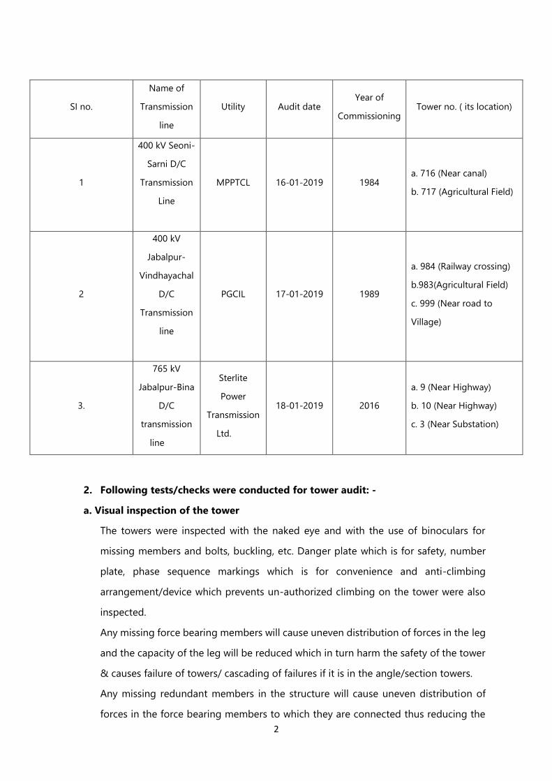
Similarly, missing bolts of member’s connection will cause reduction in strength of
joint and causing excessive stresses in the intact bolt of a joint leading failure of joint/s
& in-turn may lead to failure of tower.
Figure 1. Holes in Members
Observation: Missing of members due to theft, absence of redundant members,
bending, buckling of few members, missing of some bolts were found in the audited
towers of 400 kV Seoni-Sarni D/C Transmission. Anti-climbing device (ACD) was absent
in the two towers of 400 kV Jabalpur-Vindhayachal D/C Transmission line, bending of
a member and absence of member was found in the first two audited towers of 765 kV
Jabalpur-Bina D/C transmission, details of which can be referred from Annexure A.
Conclusion: Tower structures were found intact with some minor aberration i.e.
missing of bolts in some towers, buckling of some tower members and missing of
ACDs in some towers.
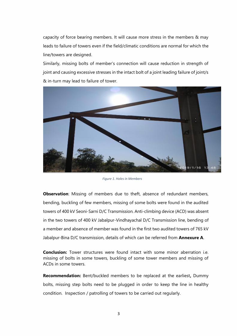
Recommendation: Bent/buckled members to be replaced at the earliest, Dummy
bolts, missing step bolts need to be plugged in order to keep the line in healthy
condition. Inspection / patrolling of towers to be carried out regularly.
4
Figure 2. Bent, Buckled Members
b. Dimensions of the base width, diagonal length, leg members, bracing members
of the bottom panel
The exact overall dimensions of tower structure as a whole like base width & diagonal
are necessary for ensuring actual strength of tower for normal functioning of tower
for which it is designed. Similarly, the size of tower members shall be within the
tolerance limit so that the strength of tower as whole will not get weakened.
The measurements of tower footings, stubs, and reachable members were taken. The
length, width and diagonal measurements of tower structure were also taken.
Observation: The recorded readings are given at Annexure A & Annexure B.
Conclusion: 1. The dimensions for members of audited towers of 400 kV Jabalpur-
Vindhayachal D/C Transmission line are within limits.
2. For 400 kV Seoni-Sarni D/C Transmission Line, except the dimensions of measured
transverse bracings of tower no. 717, rest other members of the towers of this line are
within limits.
3. For 765 kV Jabalpur-Bina D/C transmission line, except the dimension of the

5
measured longitudinal bracing of audited tower no. 9, rest other members of the
audited towers of this line are within limits.
Recommendation: Tower Drawings shall be followed during entire process of
erection. It is essential to carry out pre stringing /charging inspection for each of the
tower of a line and record the same. The members having dimensions not within limits
shall be replaced by the members having correct dimensions.
c. Galvanized coating details of members in the leg portion
The galvanized coating protects the tower material from corrosion due to various
pollutants persistent in air. The reduction/erosion of coating may lead to corrosion
and reduction in original dimensions of tower member/s thus reducing the capacity
of member/s which may lead to failure of tower. The thickness of coating was
measured with the use of Alcometer.
Observation: The recorded readings are given at Annexure A.
Conclusion: inadequate Coating thickness were found at few locations in all the
audited towers except tower no. 983 of 400 kV Jabalpur-Vindhayachal D/C
Transmission .
Recommendation: Coating thickness shall be measured periodically and prompt
action shall be taken to protect the tower/structure from corrosion by applying anti
corrosive painting.
d. Corrosion to members
Corrosion is a natural process, which converts a refined metal to its oxide, hydroxide,
or sulfide, etc. It is the gradual destruction of materials due to exposure to
environment. Corrosion leads to loss of section size of structure and in turn reduces
the strength of structure. The towers were observed for corrosion.
6
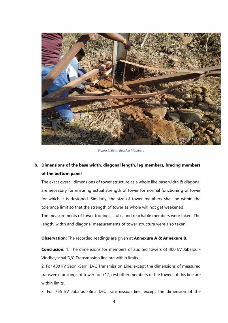
Figure 3. Corroded Members
Observation: Members were heavily corroded in the towers of 400 kV Seoni-Sarni
D/C Transmission Line, members of other transmission towers were in adequate
condition. Stubs were corroded at few locations in some of the audited towers.
Conclusion: The members, stubs have not been maintained in required condition.
Recommendation: Water logging near towers shall be avoided. Periodical
inspection and anti-corrosive painting shall be applied for the tower members
wherever onset of corrosion is noticed.
e. Differential settlements of towers
The foundation settlement occurs when the soil beneath a structure/ footings cannot
bear the force imposed by the tower structure and conductor or the design
parameters for foundation as per the soil under consideration turns erroneous. The
settlement of a structure is the amount that the structure sinks after construction in
all the four footings or differential settlement of footings. In case of uniform
settlement of tower/s there may not be much problem for the structure. However,
7
differential settlements of legs/ footings become a big problem when the foundation
settles unevenly causing additional stress in the tower members. The more uneven
in the settlement, the greater shortcoming on the safety of the structure & the
reliability causing premature failures, even when the field conditions are normal and
all the deviations are within tolerable limits. Water tube method was used to know
the differential settlement of the tower. The level of the stubs of all the four legs of
the tower was measured and compared with respect to each other.
Differential settlements may lead to following problems: -
i) Tower may tilt towards settled side that may in turn produce strain in erected
conductors and may cause snapping.
ii) Tower may collapse that will have cascading effect and adjacent towers may
also be affected.
Observation: The recorded readings are given at Annexure A.
Conclusion: Differential settlements for tower no. 716 of 400 kV Seoni-Sarni D/C
Transmission Line, tower no. 999 of 400 kV Jabalpur-Vindhayachal D/C Transmission
line and tower no. 10 of 765 kV Jabalpur-Bina D/C transmission line were not within
permissible limits, while the rest of the audited towers were within permissible limit.
Recommendation: The land around tower footing shall be compact, levelled and
kept dry to provide strength to the soil. Water logging shall be avoided if the
foundations of a given tower location is not designed for wet condition, condition and
also suitable corrective measures shall be taken for the towers where the differential
settlement is not within permissible limits.
f. Verticality of tower
This test was done to find out any undue eccentricity/leaning of the tower created
due to constructional problem if any and or created by wind, excessive line loading
buckling of towers, differential settlement of foundation, etc. The procedure
adopted for this was by identifying the center of the tower and then measuring
through the transverse & longitudinal axes taking reference of the intersection of
bracings of bottom panel of the tower and tracking through the overall height of

8
the tower up to the intersection of bracings of top panel of the tower by use of
Total station in both the directions.
Figure 4. Transverse view of Verticality
Observation: The recorded readings are given at Annexure A & Annexure C.
Conclusion: All the measured Transverse & longitudinal of towers were within
permissible limit.
Recommendation: To avoid the eccentricity & deviation in verticality, the stubs to
be casted to the correct position (Base width and Diagonal) & to the correct
inclination (slope) and also at common level. Due care shall be taken during stringing
to maintain the correct sag tension coordination for a given span.
**************

9

Line name
Tower number 716 717 984 983 999 9 10 3
Tower Type F30+3 F 60+7 C 60+14 A2+0 B 30+6 B+0 D+0 A+6
location (Near cannal) (Agricultural Field) (Near Railway
crossing)(Agricultural Field) (near road to village)
(Agricultural Field near
Highway)
(Agricultural Field near
Highway)Near Substation
Audit Date: 16-01-19 16-01-19 17-01-19 17-01-19 17-01-19 18-01-19 18-01-19 18-01-19
S/C D/C M/C D/C D/C D/C D/C D/C D/C D/C D/C
Configuration Vertical/
Horizontal, Horizontal Horizontal Vertical Vertical Vertical Vertical Vertical Vertical
Damage to TowerRepeated Theft of members of the
tower was reported by MPPCL
Repeated Theft of members of the tower
was reported by MPPCL, one of the
member was observed loose and
repeated noise of metal clinking was
heard.
Nil Nil Nil Nil Nil Nil
Bending / buckling
Bending in Members of Hip bracing
of leg B. In Leg A, the Bracing
members got bent where the
redundant member were jointed to
the bracing.
Redundant Members of Leg B were
buckled/bent & Members in Hip Bracing
of Leg A were bent
Nil Nil NilRedundant member in Leg
A is bentNil Nil
Missing MembersRedundant members in the Leg B
were absent
Redundant members in the Leg D and
Leg C were absentNil Nil Nil Nil
One member in
Auxiliary cross arm
bottom section was
missing. And the other
member was not
connected.
Nil
Missing bolts/nuts
Bolts were missing at some locations
in leg members and redundant
members
Bolts were missing at some locations in
leg C, members and redundant membersNil Nil Nil Nil Nil
Danger plate holes
were not plugged.
Leg slope alignment Aligned Aligned Aligned Aligned Aligned Aligned Aligned Aligned
Step bolts Appropriately Placed Appropriately Placed Appropriately Placed Appropriately Placed Appropriately Placed Appropriately Placed Appropriately Placed Appropriately Placed
Anti Climbing Device Present & intact Present & intact No No Present & intact Present & intact Present & intact Present & intact
Btn. Stub 1&2 11.25 m 15.38 m 14.86 m 5.95 m 11.86 m 14.52 m 17.36 m 13.76 m
Btn. Stub 2&3 11.25 m 15.37 m 14.86 m 7.95 m 11.89 m 14.5 m 17.48 m 13.76 m
Btn. Stub 3&4 11.25 m 15.38 m 14.87 m 5.98 m 11.88 m 14.53 m 17.36 m 13.74 m
Btn. Stub 4&1 11.24 m 15.38 m 14.86 m 7.95 m 11.88 m 14.54 m 17.42 m 13.74 m
Btn. Stub 1&2 4 mm down 2 mm up 19 mm down 0 mm 1 mm down 2 mm up 40 mm up 1 mm up
Btn. Stub 1&3 11.5 mm down 8.2 mmup 5 mm up 4 mm down 18 mm down 1 mm down 42 mm up 7 mm down
Btn. Stub 1&4 1 mm down 6.2 mm up 6 mm up 2 mm up 4 mm up 16 mm down 48 mm up 4 mm up
Tolerance limit 11.25 mm 15.38 mm 14.87 mm 7.95 mm 11.89 mm 14.54 mm 17.48 mm 13.76 mm
Conclusion for differential
settlement Not within limit It is within limit It is within limit It is within limit Not within limit It is within limit Not within limit It is within limit
Tower Height (in meter) 33.67 39.17 54 46.5 46 47.375 47.375 58.575
Transverse Axis defelection
(measured)211 10 300 46 29 48 42 28
Longitudinal axis deflection
(measured)101 6 86 10 69 13 104 18
Tolerance 240.5 279.79 385.71 332.14 328.57 338.39 338.39 418.39
Conclusion for verticality within limit within limit within limit within limit within limit within limit within limit within limit
Deflection / Verticality
400 kV Jabalpur-Vindhayachal D/C Transmission line
(PGCIL)
Data Sheet of Audited Transmission towers ANNEXURE A - PART A
General Information
765 kV Jabalpur-Bina D/C transmission line (Sterlite
Power Transmission Ltd.)
Visual Observations
Measured Tower Base width
Stubs levelling difference (mm) at Top of Stub
400 kV Seoni-Sarni D/C Transmission Line (MPPTCL)
Page 1

Parameter (Leg A) Size as per measurement (mm) Size as per drawing (mm) Size devaition/conclusionGalvanising Thickness
measured (microns)
Galvanising Thickness
required as per
specifications (microns)
Galvanizing thickness
deviation/conclusionCondition (for corrosion)
Stubs L 150.60x147.66x12.96x12.60 L 150x150x12x12 Deviation within tolerance limit not measured not applicable
Leg L 148.90x150.18x11.98x11.88 L 150x150x12x12 Deviation within tolerance limit 123, 63, 59, 176
Bracing L 99.90x100.80x6.40x6.66 (Trans.) L 100x100x8x8 Deviation within tolerance limit 82,65,70,84L 91.12x90.42x6.20x6.66 (Long.) L 90x90x6x6 Deviation within tolerance limit 73,55,50,125
Parameter (Leg A) Size as per measurement (mm) Size as per drawing (mm) Size devaition/conclusionGalvanising Thickness
measured (microns)
Galvanising Thickness
required as per
specifications (microns)
Galvanizing thickness
deviation/colclusionCondition
Stubs L 150.42x151.94x15.92x16.12 L 150x150x16x16 Deviation within tolerance limit few locations in Leg A & its bracings, Leg B & its bracing (long.), Leg C bracings, Leg D & its bracings (trans.) has its galvinising thickness below 86 micronsnot applicable
Leg L 149.34x149.68x15.96x16.14 L 150x150x16x16 Deviation within tolerance limit 82,75,120,81
Bracing L 112.36x110.48x8.24x8.46 (Trans.) L 110x110x8x8 not within tolerence limit 80,87,81,52
L 110.32x111.52x8.92x8.22 (Long.) L 110x110x8x8 Deviation within tolerance limit 62,78,75,96
Parameter (Leg A) Size as per measurement (mm) Size as per drawing (mm) Size devaition/conclusionGalvanising Thickness
measured (microns)
Galvanising Thickness
required as per
specifications (microns)
Galvanizing thickness
deviation/colclusionCondition
Stubs Not measured L 200 X 200 X 20 X 20 Not Applicable not measured not applicable
Leg L 200.00x200.00x20.55x20.90 L 200 X 200 X 20 X 20 Deviation within tolerance limit 148, 145, 164, 151
Bracing L 125.20x124.90x7.85x8.20 (Trans.) L 125 X 125 X 8 X 8 Deviation within tolerance limit 80,91,115,139
L 125.70x124.30x8.05x8.50 (Long.) L 125 X 125 X 8 X 8 Deviation within tolerance limit 81,129,134,145
Parameter (Leg A) Size as per measurement (mm) Size as per drawing (mm) Size devaition/conclusionGalvanising Thickness
measured (microns)
Galvanising Thickness
required as per
specifications (microns)
Galvanizing thickness
deviation/colclusionCondition
Stubs Not measured L 180 X 180 X 12 X 12 Not Applicable not measured not applicable
Leg L 182.00x182.00x11.15x11.15 L 180 X 180 X 11 X 11 Deviation within tolerance limit 206, 123, 138, 186
Bracing L 111.70x111.30x8.60x8.65 (Trans.) L 110 X 110 X 8 X 8 Deviation within tolerance limit 198, 144, 146, 127
L 91.70x88.00x6.60x6.80 (Long.) L 90 X 90 X 6 X 6 Deviation within tolerance limit 141, 151, 107, 107
Part B
Tower no. 983 400 kV Jabalpur-Vindhayachal D/C Transmission line (PGCIL)
MEASUREMENTS OF INDIVIDUAL TOWER
Tower no. 716 Seoni-Sarni D/C Transmission Line (MPPTCL)
Tower no. 717 Seoni-Sarni D/C Transmission Line (MPPTCL)
Tower no. 984 400 kV Jabalpur-Vindhayachal D/C Transmission line (PGCIL)
Except Leg A, Leg D & K Bracing
Long. Face of Leg D , every
member has the galvinsing
thickness below 86 microns
few locations in Leg A & its
bracings, Leg B & its bracing
(long.), Leg C bracings, Leg D &
its bracings (trans.) has its
galvinising thickness below 86
microns
a single location in Leg A
bracings has its galvinising
thickness below 86 microns,
rest all members have
adequate thickness
adequate thickness
some members of bottom panel were
corroded>86 micron (IS :2629)
>86 micron (IS :2629)some members of bottom panel were
corroded
>86 micron (IS :2629) normal
>86 micron (IS :2629) normal

Parameter (Leg A) Size as per measurement (mm) Size as per drawing (mm) Size devaition/conclusionGalvanising Thickness
measured (microns)
Galvanising Thickness
required as per
specifications (microns)
Galvanizing thickness
deviation/colclusionCondition
Stubs Not measured L 200 X 200 X 16 X 16 Not Applicable not measured not applicable
Leg L 201.00x201.00x14.50x15.40 L 200 X 200 X 14 X 14 Deviation within tolerance limit 134,225,205,180
Bracing L 100.20x00.60x8.25x8.10 (Trans.) L 100 X 100 X 8 X 8 Deviation within tolerance limit 164, 137, 138, 173
L 100.40x99.70x8.30x8.70 (Long.)L 100 X 100 X 8 X 8
Deviation within tolerance limit 67, 263, 167, 134
Parameter (Leg A) Size as per measurement (mm) Size as per drawing (mm) Size devaition/conclusionGalvanising Thickness
measured (microns)
Galvanising Thickness
required as per
specifications (microns)
Galvanizing thickness
deviation/colclusionCondition
Stubs Not measured HT 150*150*15 Deviation within tolerance limit not measured not applicable
Leg L 148.00x148.00x15.50x15.40 L 150*150*15 Deviation within tolerance limit 83, 95 ,86, 88
Bracing L 99.20x99.10x8.10x8.10 (Trans.) 100*100*8 Deviation within tolerance limit 81, 81, 65, 61
L 102.10x102.60x7.30x7.50 (Long.) 100*100*7 not within tolerence limit 84, 97, 73, 77
Parameter (Leg A) Size as per measurement (mm) Size as per drawing (mm) Size devaition/conclusionGalvanising Thickness
measured (microns)
Galvanising Thickness
required as per
specifications (microns)
Galvanizing thickness
deviation/colclusionCondition
Stubs Not measured HT 150*150*20 Not Applicable not measured not applicable
Leg L 150.00x148.00x20.00x20.00 L 150*150*20 Deviation within tolerance limit 95, 87, 108, 109
Bracing Inner L 91.20x89.00x6.80x6.30 Outer L
90.20x88.00x6.60x6.70 (Trans.)
Inner L 90*90*6
outer L90*90*6 Deviation within tolerance limit 92, 81, 102, 86
Inner L 74.80x74.00x6.10x6.20 (Long.) Inner L 75*75*6 Deviation within tolerance limit 78, 83, 70, 98
Outer L 74.40x74.00x6.70x6.20 (Long.) outer L 75*75*6 Deviation within tolerance limit
Parameter (Leg A) Size as per measurement (mm) Size as per drawing (mm) Size devaition/conclusionGalvanising Thickness
measured (microns)
Galvanising Thickness
required as per
specifications (microns)
Galvanizing thickness
deviation/colclusionCondition
Stubs Not measured HT130*130*10 Not Applicable not measured not applicable
Leg L 131.45x129.40x10.20x10.30 L 130*130*10 Deviation within tolerance limit 114, 111, 92, 93
Bracing L 79.60x9.60x6.40x6.20 (Trans.) L 80*80*6 Deviation within tolerance limit 87, 105, 84, 86
L 75.20x74.30x6.35x6.40 (Long.) L 75*75*6 Deviation within tolerance limit 83, 145, 78, 88
* long. = longitudinal * trans = transverse *long = longitudinal
Tower no. 999 400 kV Jabalpur-Vindhayachal D/C Transmission line (PGCIL)
Tower no. 10 Jabalpur-Bina D/C transmission line (Sterlite Power Transmission Ltd.)
Tower no. 3 Jabalpur-Bina D/C transmission line (Sterlite Power Transmission Ltd.)
>86 micron (IS :2629) normal
>86 micron (IS :2629) normal
few locations in Leg A
bracing(long.), Leg B bracings,
Leg C bracing (long.) has its
galvinising thickness below 86
microns
few locations in Leg A
bracing(long.) , Leg C & Leg D
bracing (trans.) has its
galvinising thickness below 86
microns
>86 micron (IS :2629) normal
>86 micron (IS :2629) normal
Tower no. 9 Jabalpur-Bina D/C transmission line (Sterlite Power Transmission Ltd.)
a single location in Leg A
longitudinal bracing has its
galvinising thickness below 86
microns, rest all members have
adequate thickness
few locations in Leg A & its
bracings, Leg B bracing (trans.),
Leg C & its bracings, Leg bracings
has its galvinising thickness below
86 microns

Size Tolerance</=45mm +/- 1.5mm
>45mm & >/= 100mm +/- 2.0mm
>100mm +/- 2%
Galvanising Coating thickness: 610 g/sq.m Min. thickness 87 microns
Diff in Elevation of Stubs: </= (1/1000)*base width
</=1/360*height (under test
bed/ without stringing)
<= 1/140* height with
stringing (up to 60 m height) *
Suggested by CSIR-SERC
Flange length/leg length
Description
Verticality of Tower

Annexure-B
CSIR-STRUCTURAL ENGINEERING RESEARCH
CENTRE TOWER TESTING AND
RESEARCH STATION
313(CEA_Audit)/2019-RPR
30th January 2019
To
The Chief Engineer,
Chief Electrical Inspectorate Division,
Central Electricity Authority,
18-A, Shaheed Jeet Singh Marg,
Katwaria Sarai New Delhi-110016
Sub: Observations of 4th pilot audit of transmission line towers – Reg.
Dear Sir,
Following are the observations made during the 4th pilot audit of Transmission Line
(TL) towers:
1) Total eight numbers of towers were audited in three days in three different
transmission lines. The general observations are missing secondary bracing
members (refer Fig. 1), unplugged bolt-holes and missing bolts in the bottom
panel. The missing members and bolts need to be replace immediately as per
the respective original structural drawings. Further, all the open bolt-holes have
to be plugged with bolts or welding.
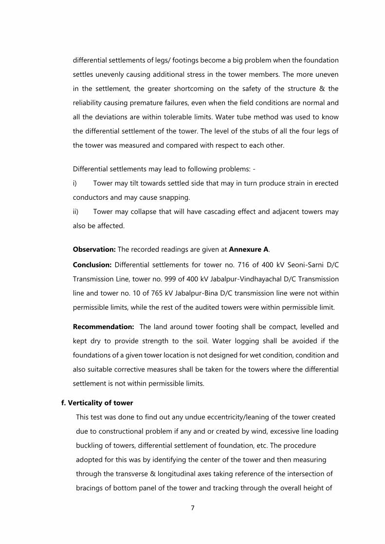
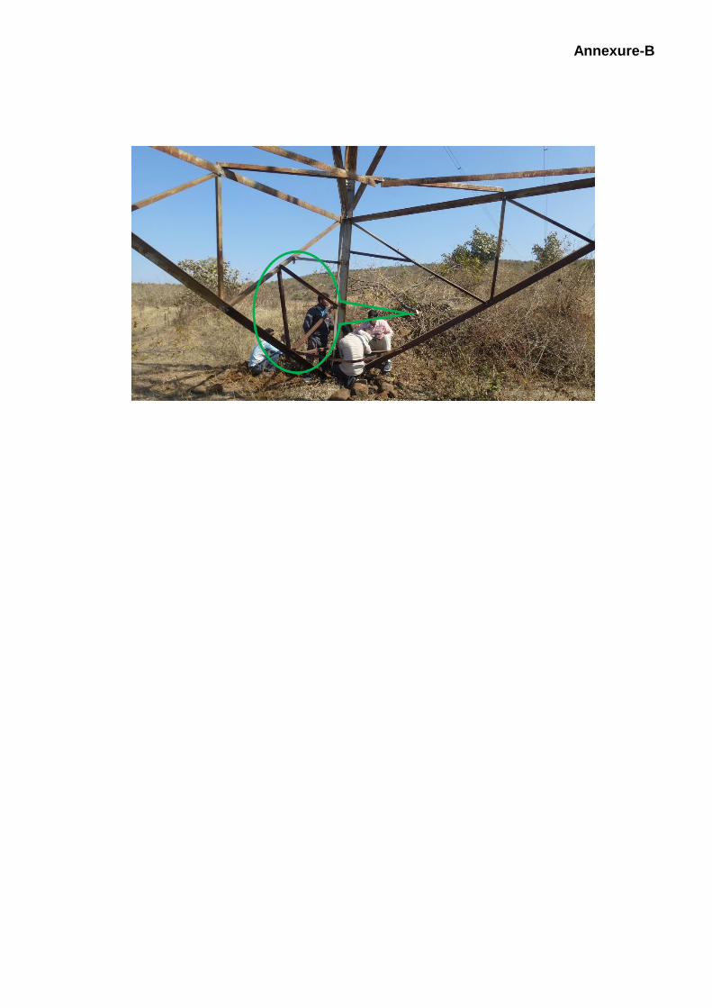
2) Improper rectification/ replacement of stolen members (by cutting the original
members) was observed for the first tower audited on 16/01/2019 in the 400 kV
Seoni - Sarni TL, which is operated and maintained by M/s MPPTCL. For fixing
the new member in place of stolen/missing member additional holes were drilled,
which creates eccentricity leading to additional forces in the structure. Most of the
secondary bracing members are bent during the rectification work. In some
places replaced member has two pieces connected with single bolt in one of the
flanges. All the above representative deficiencies are indicated in Fig. 2. In order
to ensure the safety and stability of TL tower, it is necessary to carry out proper
rectification immediately as per the structural drawings.
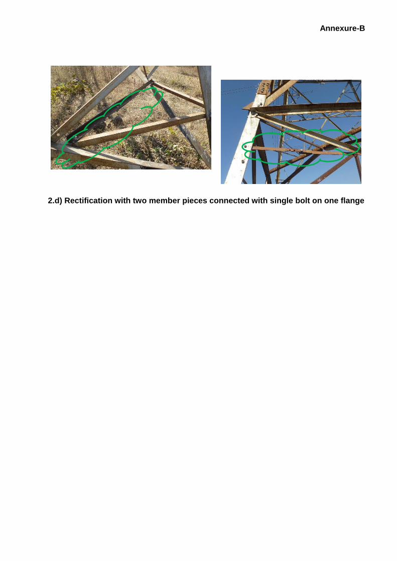
3) The section dimensions measured during the audit for all the towers at bottom
panel main members are presented in Table-1.

Annexure-B
For TL tower audit, the following instruments in working condition are required to
carry out the tower measurements accurately and efficiently,
a. Digital Vernier calliper minimum 30 cm long with least count 0.01 mm.
Calibration/ checking for proper functioning prior to the audit is must for
the digital Vernier callipers. In addition, a steel scale of 30 cm length is
necessary.
b. Micrometre screw gauge with least count of 0.001 mm for member
thickness measurement.
c. Steel tapes of 5m and 30 m length in good condition.
d. Drone camera with laptop for checking the condition of tower at different
heights.
e. Total station theodolites with reflector prism, other necessary accessories
and skilled operator to take the measurements in optimum time.
f. Instrument for galvanising thickness measurement with proper calibration.
g. Other accessories like levelling tubes of minimum 20 and 30 m length,
nylon wire for tower diagonal measurement, earthing resistance
measuring equipment etc.
For better serviceability of the TL towers,
i. Condition assessment of tower and foundation has to be carried out using
non-destructive techniques at least once in 5 years and
ii. The strengthened tower design designs have to be proof checked every
15 years with respect to for the latest design standards
R.P. Rokade
(Principal Scientist)
Annexure-B

Annexure-B
Fig. 2 Tower-1 Audited on 16/01/2019 2.b) Unplugged Holes
2.c) Bent/sagged members
Annexure-B
2.d) Rectification with two member pieces connected with single bolt on one flange
Annexure-B
Table-1 4th Pilot Audit for Audit of Transmission L ine Towers - Details of Member Section
Dimensions
Audit
Date
Trans. Line &
Agency Tower
No. Tower
Member
Member Section Dimensions Refer
Tower
Location
Figure
Leg-A Leg-B Leg-C Leg-D
16-01-
2019
400 kV
Seoni - Sarni
Transmission Line
M/s MPPTCL
1
Stub L
150.60x147.66x12.96x12.60 L
149.90x149.40x12.64x12.20 L
149.94x149.12x12.42x12.64 L
149.52x150.52x12.12x12.12
Fig. 3 - 1
Leg L
148.90x150.18x11.98x11.88 L
150.62x150.40x11.68x11.94 L
149.34x149.82x12.12x12.82 L
149.62x151.10x11.82x12.42 Trans.
Bracing L 99.90x100.80x6.40x6.66 L 99.86x99.42x6.18x6.14 L 99.12x99.52x6.22x6.42 L 99.22x99.82x6.92x6.86
Long.
Bracing L 91.12x90.42x6.20x6.66 L 91.90x90.10x6.60x6.42 L 91.72x89.42x6.52x6.72 L 91.22x90.34x6.82x6.62
2
Stub L
150.42x151.94x15.92x16.12 L
152.14x152.12x16.12x15.96 L152.42x151.62x15.92x16.18 L
152.42x152.22x16.42x16.92
Fig. 3 - 1
Leg L
149.34x149.68x15.96x16.14 L
150.42x148.32x16.22x16.12 L
149.72x150.58x16.12x16.38 L
150.12x151.12x16.48x16.34 Trans.
Bracing L 112.36x110.48x8.24x8.46 L
110.12x106.22x10.82x10.42 L 111.54x110.78x8.56x8.32 L 111.12x110.92x8.54x8.62
Long.
Bracing L 110.32x111.52x8.92x8.22 L 100.46x100.82x8.64x8.42 L 100.68x100.72x8.48x8.28 L 109.74x111.32x8.72x8.82
17-01-
2019
400 kV
Jabalpur -
Vindhyachal Transmission
Line M/s PGCIL
1
Leg L
200.00x200.00x20.55x20.90 L
200.00x200.00x21.00x21.05 L 200.00x00.00x21500x20.80 L
200.00x200.00x20.70x20.50
Fig. 3 - 2 Trans.
Bracing L 125.20x124.90x7.85x8.20 L 126.50x123.60x8.65x8.30 L 125.75x125.90x9.90x8.80 L 125.90x125.10x8.70x8.90
Long.
Bracing L 125.70x124.30x8.05x8.50 L 126.10x125.20x7.65x8.80 L 126.30x125.00x8.70x9.20 L 125.10x126.10x8.25x8.65
2 Leg L
182.00x182.00x11.15x11.15 L
181.50x181.50x11.30x11.10 L
179.00x180.00x12.00x12.00 L
182.00x179.00x12.00x11.60
Fig. 3 - 3 Trans.
Bracing L 111.70x111.30x8.60x8.65 L 111.10x109.00x9.00x9.00 L 110.15x111.00x8.80x8.10 L 109.15x111.60x8.55x8.30
Long.
Bracing L 91.70x88.00x6.60x6.80 L 91.90x90.85x6.55x7.90 L 91.50x90.50x6.30x6.75 L 89.00x88.45x6.50x7.70
3 Leg L
201.00x201.00x14.50x15.40 L
201.00x201.00x15.20x15.05 L
201.00x199.00x15.30x15.30 L
200.00x200.00x14.90x14.30 Fig. 3 - 3

Annexure-B
Trans.
Bracing L 100.20x00.60x8.25x8.10 L 100.60x99.80x9.20x9.30 L 100.85x100.40x8.50x8.80 L 100.90x100.80x8.70x8.45
Long.
Bracing L 100.40x99.70x8.30x8.70 L 100.70x101.30x8.25x8.30 L 100.40x100.00x8.90x8.90 L 100.00x100.00x8.15x9.00
18-01-
2019
765 kV
Jabalpur - Bina
Transmission Line
M/s Sterlite Power
Transmission
Ltd.
1
Leg L
148.00x148.00x15.50x15.40 L
150.00x150.00x15.30x15.20 L
148.00x150.00x15.50x15.30 L
148.00x150.00x15.30x15.00
Fig. 3 - 3 Trans.
Bracing L 99.20x99.10x8.10x8.10 L 100.70x99.30x8.50x8.20 L 100.30x99.20x8.60x8.10 L 99.50x01.20x8.20x8.20
Long.
Bracing L 102.10x02.60x7.30x7.50 L 100.30x99.00x7.00x7.30 L 103.50x101.40x7.40x7.30 L 99.80x99.30x7.00x7.00
2
Leg L
150.00x148.00x20.00x20.00 L
150.00x148.00x20.00x20.00 L
152.00x150.00x20.00x19.80 L
148.00x150.00x20.00x20.00
Fig. 3 - 4
Trans.
Bracing
Inner L
91.20x89.00x6.80x6.30 Inner L
90.40x88.00x6.50x6.20 Inner L
91.90x90.00x6.25x6.30 Inner L
90.50x88.00x6.30x6.20 Outer L
90.20x88.00x6.60x6.70 Outer L
91.30x89.00x6.20x6.30 Outer L
90.10x89.00x6.30x6.20 Outer L
90.40x89.00x6.50x6.00
Long.
Bracing
Inner L
74.80x74.00x6.10x6.20 Inner L
75.40x73.00x6.20x6.10 Inner L
75.70x75.00x6.25x6.40 Inner L
75.00x75.00x6.20x6.30 Outer L
74.40x74.00x6.70x6.20 Outer L
75.00x73.00x6.50x6.20 Outer L
75.20x75.00x6.50x6.35 Outer L
75.20x74.00x6.30x6.20
3
Leg L
131.45x129.40x10.20x10.30 L
129.90x130.25x10.20x10.20 L
130.90x130.30x10.25x10.35 L
130.20x130.30x10.70x10.25
Fig. 3 - 5 Trans.
Bracing L 79.60x9.60x6.40x6.20 L 79.40x79.10x6.20x6.20 L 79.40x80.20x6.20x6.20 L 79.20x79.40x6.30x6.45
Long.
Bracing L 75.20x74.30x6.35x6.40 L 77.70x73.50x6.60x6.20 L 76.00x74.90x6.25x6.20 L 75.20x75.40x6.20x6.10
Section Dimension Nomenclature for Stub/Leg Member : L - Angle Section Trans. Face Width x Long. Face Width x Trans. Face Thk. X Long. Face Thk.
Section Dimension Nomenclature for Bracing Member : L - Angle Section Horz. Face Width x Vert. Face Width x Horz. Face Thk. X Vert. Face Thk.
Abbrevations used : Trans. - Transverse, Long. - Longitudinal, Horz. - Horizontal, Vert. - Vertical
Tower Location Figures for Leg Identification

Annexure-B

Annexure-B
Fig. 3 – 1 for Towers Fig. 3 – 2 for Tower-1 Fig. 3 – 3 for Towers 2 & 3 Audited on 17/01/2019
Audited on 16/01/2019 Audited on 17/01/2019 and Tower-1 Audited on 18/01/2019
Fig. 3 – 4 for Tower-2 Audited on
18/01/2019 Fig. 3 – 5 for Tower-3 Audited on
18/01/2019
Annexure-C
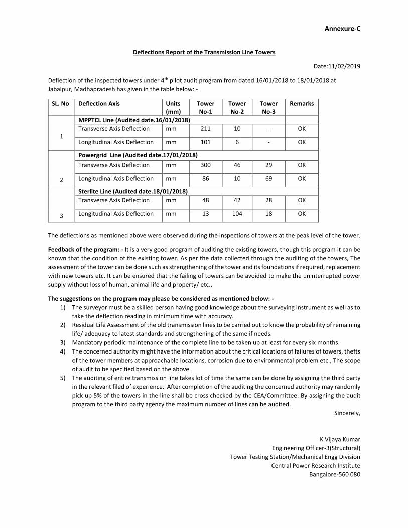
Deflections Report of the Transmission Line Towers
Date:11/02/2019
Deflection of the inspected towers under 4th pilot audit program from dated.16/01/2018 to 18/01/2018 at
Jabalpur, Madhapradesh has given in the table below: -
SL. No Deflection Axis Units (mm)
Tower No-1
Tower No-2
Tower No-3
Remarks
1
MPPTCL Line (Audited date.16/01/2018)
Transverse Axis Deflection mm 211 10 - OK
Longitudinal Axis Deflection mm 101 6 - OK
2
Powergrid Line (Audited date.17/01/2018)
Transverse Axis Deflection mm 300 46 29 OK
Longitudinal Axis Deflection mm 86 10 69 OK
3
Sterlite Line (Audited date.18/01/2018)
Transverse Axis Deflection mm 48 42 28 OK
Longitudinal Axis Deflection mm 13 104 18 OK
The deflections as mentioned above were observed during the inspections of towers at the peak level of the tower.
Feedback of the program: - It is a very good program of auditing the existing towers, though this program it can be
known that the condition of the existing tower. As per the data collected through the auditing of the towers, The
assessment of the tower can be done such as strengthening of the tower and its foundations if required, replacement
with new towers etc. It can be ensured that the failing of towers can be avoided to make the uninterrupted power
supply without loss of human, animal life and property/ etc.,
The suggestions on the program may please be considered as mentioned below: -
1) The surveyor must be a skilled person having good knowledge about the surveying instrument as well as to
take the deflection reading in minimum time with accuracy.
2) Residual Life Assessment of the old transmission lines to be carried out to know the probability of remaining
life/ adequacy to latest standards and strengthening of the same if needs.
3) Mandatory periodic maintenance of the complete line to be taken up at least for every six months.
4) The concerned authority might have the information about the critical locations of failures of towers, thefts
of the tower members at approachable locations, corrosion due to environmental problem etc., The scope
of audit to be specified based on the above.
5) The auditing of entire transmission line takes lot of time the same can be done by assigning the third party
in the relevant filed of experience. After completion of the auditing the concerned authority may randomly
pick up 5% of the towers in the line shall be cross checked by the CEA/Committee. By assigning the audit
program to the third party agency the maximum number of lines can be audited.
Sincerely,
K Vijaya Kumar
Engineering Officer-3(Structural)
Tower Testing Station/Mechanical Engg Division
Central Power Research Institute
Bangalore-560 080