report no. 732 - nasa · · 2013-08-31report no. 732. pressure ... % g%@ presented a8 ‘premure...
TRANSCRIPT

REPORT NO. 732.
PRESSURE DISTRIBUTION OVER AN NACA 23012 AIRFOIL WITH A FIXED SLOTAND A SLOTTED FMP
By THOU A. Eums and JOHN C?. Low-m
SUMMARY m
A pmwurdistrhdhn inueetigation w conducted intlw LM& 7-by iO-foot wind tunnd to (ktermine the airlode on an iVACA %OM airfoil in combination with aj%cedLmding+?dgetdotand a 8~otted$ap. Prewures weremeasured mer the upper ad lower eurfirms of th4 mn-pon.mt parik of the oombi&n for semwl angk8 ofa.t!ack and at wvemljlap 8ettiqJ8.
% G%@ presented a8 ‘premure diagra?n8 and grapheof mtion coejicienti, are applicable b m-b, dizt, and $apdesigns for the combinai%m. The data ~howed the fii-%ng: % peak pre88ure8 d the no8t?Of h 8kt and the
‘ I?oadeon the 8.hI#were higher in thi? angle-of-atiaok rangewhere 8kIte art? uaefd thun @e peak pre%urea and thehnzde S* in preuiouely pwblished data on the HandkyPage type of 8tot. The kmi=8 on the 8k#ted $ap 8hmoedonly a 8@ht chunge un”thth%addition of a kaxhg-edge8kIt, and d is belimed thd any conoentimd $ap woufd8how dy a 8@ht change in kmding if incorporated withajxe.d leading-edge 81oL
INTRODUCTION
The National Advisory Committee for Aeronauticshas undertaken an extensive investigation of air Ioadaon high-Iift and stall-prevention devices to obtain datauseful in the design of safer airphmes. With the in-crease in wing loakg and the use of highly taperedwings, some device is necessary to improve the stalhngcharacteristics of the wing. There are several waysin which these unadmirable oharaoteristica can beimproved. One method now being employed is theaddition of a leading-edge slot to the tip section ofthe wing.
The simpkt kading-edge slot to construct andoperate is the &d slot described in reference 1; in
this me the SIatis an integral part of the wing. Thistype of slot has the disadvantage of increasing the dragat the h~h-speed condition but may be advantageouswhere ruggedness and simplicity of construction areessentiaI.
Two types of movable leading-edge slot are theHandIey Page (reference 2) and the MaxwelI (reference3), whioh are fornied hy the movement or rotation ofthe SIat with respect to the main airfoil. Some loaddata are available on the Handley Page type of slot
(references 2 and 4). This type of sIot is advantageousb~ause it produces little increase in drig at high+peedconditions and is more effective than the fixed slot, butits construction and operation offer difFLcuMes.
The present investigation inoludes load data for theoptimum fixed-slot arrangement reported in reference 1and for a slotted flap on an NACA 23012 ,airfoil.
APPARATUS AND’ TESTSMODEIS
The airfoil model used in these ksts had a 7-footspan and a 3-foot chord; it conformed to the NACA23012 airfoil profle (table 1) and was constructed ofkminated mahogany, with a‘ hollow section to accomm-odate the capper pressure tubes. The basic modelmnsisted of the airfoil in combination with a full+pan
h
“:~rl
..—. —
““m
... ‘.-.’.-’..--’
m-Q “256(5C
l-l&“.MOc
FIGG”RBL-Crwd sedkm of modd shodng a&foI140t4.lap combinatkm used Inpmmnm-dktdbution task ,
fixed Iedng-edge slot. and a full-span dotted flap(fig. 1). The M slat was attached to the airfoti byfour thin mettd fittings and the slotted flap was at-tached to the airfoiI with tbxee metaI hinges.
The full-span leading-edge sIott(fig. 1) was davelopedby the NAC.A and is designated now 11, slat 5C inreferenoe 1. The SIat has a chord of 5.940 inches(16.50 peroent of the over-aU airfofl chord). Thetrsiling+dge portion of the slat was constructed ofa.huninumso that it maintains ita shape under load.
The fuhpan aIotted flap (table I) was developed bythe NACA and is designated 2–h in reference 5. Ithas a chord of 9.238 inches (25.66 percent of the over-SU airfoiI chord). The path of the flap nose (table I)is the optimum one repcn-tedin reference 5. The flapwas arranged for looking at downward, or positive,flap deflections from 0° h 60° in 10° increments.
85
https://ntrs.nasa.gov/search.jsp?R=19930091811 2018-06-01T23:26:05+00:00Z

86 REPORT NO. 7i3%NATIONAL ADVISORY COM-idlTTEE FOR AERONAUTICS
The model was fitted with a single chordwke row ofprcwsnmeorifices 21 inches from one end of the airfoiland located along the chord as shown in table II and@ure 1. Tubes leading from these ofices werebrought out ihrough one end of the wing (fig. 2) andconnected to a dndtiple-tube manometer that recordsphotographically.
i!
r“”v;--’●
7I
I
)Ill
I
.-
11.1.;:; 1$ 1 I \
~, ill ‘]/’2”v Vertical sectian
FIGUEX2.—Morlel fnatallatlon for two—dhmhd flow tests In tha 7-by M-footwhd ~umeL
TEST INSTALLATION
The model was mounted in the closed test smtion of‘ the NACA 7- by 10-foot wind tunnel (reference 5).
Because the model completely spanned the tunnelexcept for small clearances at each end (fig. 2),approximately twc-dimensional flow was obtained.Torque tubes attached to the balance frame held themodel rigid and aIsc served as conduits for the pressuretubes. The angle of attack was set from outside thetunnel by rotating the torque tubes with a calibratedelectric drive.
TESTB
The teeti, except for those at large angks of attackin which the dynamic pressure was lowered as much as19 percent, were run at an average dynamic possumof 16.37 pounds per square foot. The decrease indynamic pressure was necessary to measure the peakpressures because of limitations in the manometer.The average dynamio pressure, 16.37 pounds persquare foot, corresponds ta a tunnel velocity of 80miles per hour and a test Reynolds number, based onthe chord of the airfoil with flap retracted, of 2,190,000.Because og the turbulence in the air stream, the cfTec-tive Iteynolds number was 3,500,000. (See reference 6.)
The modeI was tested with the sIotted tip deflectidfrom 0° to 60° in 10° increments. Teste were made ateach flap deflection through an angle-of-attuck rangofrom about zero lift to approximately maximum lift in4° increment.a. With the model at a given angle ofattack and flap setting, time was allowed for the tunneland for the manometer to become stable before thopressureawere recorded.
PRESEFJTATIONOF DATA
PEIWSUItE DIAGItAMS
All the diagrams of pressures over the upper andlower surfaces of the airfoil-elotAlap combination megiven as pressure coefficients Pwhere
p=?
and
g statio pressure at a point on airfoiIPOstatio pressure in free air streamq dynamic pressure of free air stream
Pressures over the airfoil with the fixed slot areshown in figure 3 and pressures over the airfoiI with thofixed slot and the slotted flap are shown in figuroa 4to 10. A comparison of the loads on the pIain airfoilwith the loads on the slotted airfoil is shown in figure11, and a comparison of the loads on the pIain airfoilwith slotted flap with the loads on the slotted airfoilwith slottad flap is shown in figure 12.
In figures 3 to 10 the pressures over the main airfoiland the slat are plotted normal to the airfoil chord andthe pressures over the slotted flap are plotted normalto the undeffeoted flap chord line. In order to preventoverlapping of the component parts of the combinationand to keep the mrves as Iarge as possibIe, the slat wasmoved forward and the &p was moved rearward fmmthe normal positions. The pressures are plotted forthe component parts in the positions shown by didlines. The norrmd positions of the slat and the flapare shown by dashed lines. The pressures over themain airfoil and the slat for &urea 11 and 12 are

PRESSURE DISTRIBUTION OVER NACA 23012 ~IL WITH FIXED SLOT AND SLO’ITED FLAP 87
pIotted normal to the airfoil chord, and the pressureover the slotted tip are plotted normal to the deflects{flap chord line. The position of the component patiin these figures is normal.
COEFFICIENTS
The prassure diagpmnswme mechanically integratedto obtain data hmn which standard nondimensionalsection coe.flicients were computed. Where the tam“fip done” or “&t done” is used, it refers to thforces and the momente on the flap or the slat in thepresmce of the rmt of the airfoil-slokflap combination,The section coefficients are de&ed as folIows:
norrnaI-force coe%icient of slotted airfoil withflap (n/gc)
normal-force codliciant of flap alone (?bJqcJ
normal-force coefficient of slat alone (nJgc,)chord-force coefficient of slat aIone (z,/qc,)resultant-force coefficient of slat alone
(d&x)pitching-moment coefficimt of slotted airfoil
with flap about quarter+hord point of air-foil (m/g&)
pitching-moment coeilicient of flap alone aboutquarter-chord point of flap (mJgc~
pitching-moment co*cient of normal forceof skt aIone about leading edge of sIat(?n%/qc,q “
pitching-moment coefficient of chord forceof s~at done about h?ading edge of dat(?nrjgc:)
pit&ing-moment coefficient of slat aIoncabout leading edge of slat (c.z~+cm%)
Centeraf-pressure Iocation of slotted---airfoiltith flap in percent airfoil chord bxnn Iead-
ing edge of airfoiI[(”’’-%)x’””]
centm-of-pressure location of flap al&e inperrent flap chord from Iea@g edge of flap
[o’’-:)x’””lcenter-of-presum Iocation of slat aIone in
percent sIat chord from Ieading edge of sIat
(c=
–=X1””) ●
G4=
center+f-premure Iocation of slat aIone inpercent slat chord above chord line of sIat
normal force on slottd airfoil with flapnormal force on flap alone normaI to chord of
flapmM90-4s-7
ntZ*
m?nfm%
m,=
cCfc,
and
normal force on slat clonechord force on shit alonepitohing mommt of slotted airfoiI with flappitching moment of flap alone “pitching mommt of slat aIone a’bout Ieading
edge of sIat, due b normaI forcepitahing moment of slat aIone about chord
Iine of slat, due to ohord forcechord of airfoil with flap neutmdchord of sIot&d flap (over-alI Iength of flap)chord of s~at (projected distance along airfoil
chord Iine) (See f3g. 1.)
Q% angIe of attack for Mnite aspect ratio6, angIe of flap deflection
With the exception of the chord-force moment of thesIat, the coellkiante for the combmtion w~e derivedfrom the norrmd forces alone, the chord force of the flapbeing negkted. Negkcting the normal-force mm-ponent of the chord force on the flap in cakulatiom forthe combiition reduced the normal-force c03flicientsby a maximum of approximatdy 0.08. Because thedrin fiction of the flap wilI enter into any cmreotionEorthis discrepancy, no attempt was made to include~ correction for flap-chord force in, the &al resukbmnmch as the modeI mmpletdy qpanned the jet,tie integrated rcmdtsj which are in coefbient form,may be used as section characteristics.
Figures 13 to 16 show the section characteristics of&e combination, of the slat alone, and of the flap aIone.Figure 15 shows n vectorial representation of thexxuikant-force coeflkient on the sIat alone.
PRECISION
Experhmmt.al errors in the results presented in this“eport are bdieved to be within the followirg Iimits:?-_______ i&_________________________ &2 percent[------------------------------------ +1 percent%------------------------------------------ Ao.l”if____________________________________ &“.50
The normaI-force coefficient of the combination wasmrected as expIained in refmace 5. This correction:ends to reduce the magnitudes of the pressures; theresultsfor the &t and the flap, which me uncorrected,hould be conservative.
DISCUSSION
SECTION PBESSUItE DISTEISUTION
The pressure curves (figs. 3 to 10) show the distribu-tion of pressure over the upper and lower surfaces OFhe airfoif for various combinations. These curve9nay be used for deai@ng of ribs, slats, and flaps aswII as for showing the change in distribution as theIap is deflected. In general, th~e curves show thathe fixed slot has little effect on the net pressure dis-tributionexcept that it maintains flow above the stallange for the plhin wing.
. . .

-a3~ Chord Iine-.l ..@y”~ ._ _.+=’z_&~%Chord line.. ___ . . ...._. ---
0“
-M
-12
-to
P
-8
-6
:4
-2
a
I
------- - 8.—--——- ;:0 @per surfaceA Lower “
\i
-14
-/2
-16
P
-6
-6
-4
-2
c
I
ao,d;g
-.----- - 8—.-—— - 4: -
0 L@er surfaceA Lower ‘“
-4----- +---- ----
z0
e

.-6@;~.-.-===pz+z~ -c .●.->--
Chcrd line.. /--- -Q. Chord line..----.... .. ,
<q’ @--–-
-It
-i4
-i;
-/l
P
-1
-.5
-4
------- . 8—-.——. ;:
o @per surfaceb ~Ower It
“ ‘i6
-i4
-i!z
-10
P
“8
-6
-4
-=4
@, ffeg—-
. . . . . . . .—— . 2$
0 i@per surfaceA Lower R
\
i
\
i
FIIIo%~6,-PrMTIM dlatrlbntton on tbo NAOA Z3C112alrtoil with tbo dxad dot and 0.2M6cslothd tlsp SttiOM ~@E of nttnok, fip dOd13Ct[O~10”, FIOUBB11.-Pmmura dlstrtbntlon on tho NAOA 98012alrfotlwith tbe @d dot mud0.!J6Mcclotted !kp U w
lowangh d ●rook. Fllp dodwtlo~ 23”,
.
.
,,,: i

-18
‘/6
-14
+2
-lo
P
-8
‘6
-4
-2
4
)
*, geg—-
-16
-14
+2
.0------- _
—— - f$lo L@per surfaceb Lower w
-lo
P
-8
.-6
-4
An/// ‘.\,#--q ‘
3// “\\:a%
llf==’~b---2-
P“-=-i+
~— -------—..
. 0-*&----*----y&~- ——
-=== 1-
a,,deg—- -:
--- ..----—-- 1$
0 L&er surf9ceA Lower *’
zo

.
-16
-14
+2
-10
‘P
-(5
-6
-4
-2
G
I
.
C#O,o’fq—- -;--------—-. i
0 @per surfoceA Lower *
“i:\ /
L~,,..,.-..
-18
-16
-14
-12
-/0
P
-8
-6
-4
-2
0
1
0--------——. 1:
0 @per surfaceA Lower II
#l
.& . ...*...- L,U ---- + -
mum 9.–Pmsnuradistribution on tha NACA 28012 alrfoUwith thatlrcdnlotsad 0.’2WCdottedfip nt PIOtiE 10.-PrwuIra dktdhltb on tha NAOA ~M dtiO!] with the fIX~ slotand- Sbttdf@VMow anelw0(attaok.Flapdenmtton,00”. at VW1OIUnww ofattnok.mapdeiIeoUon,OOO.
,,

92 REPORTNO. 73*NATIONM ADVXSORYCOMMX!ITEllFOR AERONAUTICS
The shapeaof the presmm curves for the model withthe slotted flap deflected (figs. 4 tQ 10) are generdyvery similar to those of the curvw for the slotted flapdeflected on a plain NACA 23012 airfoil (reference 7);this similarity shows that the flaps have the samecharacteristic as to extent of peak pressure, occurrence
I
\
— P/oilOkfoil &- 1.31[reference 7)-4 \ ---- slotkcf airfoil cm-/,38
‘.
P]
-2- ‘.,\
o-
FIOUM 11.-Compexkon 01 tbe PmSUI@ dhtrtbution on tho NACA 230128bfO~
with a fixed clot with that on a plaln NACA 2K112ahfotl. apl~.
of double peak pressures, and magnitude of peak nega-tive pressures No chord-form diagrams were includedin this report because of the simihwity of pressureson the slotted flap in this investigation to pressureson the slotted flap reported in reference 7 and becausesuch diagrams can bo constructed from normal-forcodiagrams.
The pressure curves for the fixed slat (&s. 3 to 10)are similar in. general shapo to the curves shown inreferences 2 and 4, but the maximum peak negativepressures are muoh higher on the fixed slat than theywere on the Handloy Page typo of slat. The extremeIyhigh negativo pressures (P= –18) at the now of theslatmight be fiery detrimental at relatively high &@anospeeds because of compressibility effecte. A carefulinspection of the prwsure curves will show that thelocation of the extremely high negative valuee of Pis very critical. It is quite possible, therefore, that inthe previous investigations of Handley Page slots thepressureorifices were so located that they inadvertentlymissed these high negative pressures. Diagrams showthat the pressure vru-iation over the lower surface. ofthe slat is similar to the prewmre variation over thelowar surface of the main airfoil at the slot entry forthe sIotted flap.
The preaaure diagrams for the center prtion of theairfoil (figs. 3 h 10) show a similarity to the pressurediagrams for a slotted flap.
The similarity of flow about the main portion of theairfoil for several airfoil-flap arrangements (reference 8)indicates that the forces on the fied slat in combinationwith any of the flaps would have approximately thesame pressure curve as to magnitude of preaeuree andgeneral shape. Because the addition of the bed slothad little effect on the pressures on the slotted flap, it
is reamnabIe to ass~e that the pressures on otherflapswould be onIy slightly changed. It is to be remem-bered that the forem on the slat would change withany alteration in shape of slat or slot.
A comparison of the pressures over tlm plain airfoilwith pressures over the slotted airfoil at the same angle~f attack (fig. 11) and a comparison of the prcsnms>ver the plain airfoil with slotted flap with the pres-mre$ over the slotdml airfoil with slotkd flap at thewme angle of attack (fig. 12) show the following: Theplain and slotted combinations both carry about thewuneload. The addition of the slot does not changapeak nom pressure h any extent. Tho center portion]f the slotted airfoil carries moro load and th slat:arries less load than a proportional section of plain~irfofl. The load on the flap is slightly increased bythe addition of a. slot.
The main effect of the tied slot on tlm plain airfoilwith dotted flap is to increase tho angle of attack for .the stall. The continuation of flow about tho airfoilat high angles of attack accounti for the oxtrwnelyhigh vahms of P obtained.
FY&I airfdl &h sloifad flopc. -2.49 (refa-ence 7)
------ SkJtee;;lbil w% Shfkf f~
K-6 \
p ‘\,I i\
i
\\\
-2 -
0
/-
FmvR812.-0om_ c4the prwsumdtetribution on tbn NACA =1~ difollwith a H dot and ●OSSddcalottal dsp wltb thatons pWn NAOA ZKIIAtbfotlwItb0.25Mcdottedtip.~p derlectlw w q-lP’.
AERODYNAMIC SE~ON CEARACTER1STIQ3
A compariem of the section characteristi~ for thecombination (%. 13) with results reported in refer-ences 1 and 7 shows the following: Tho normal-forcecoefbienta for the combination agree very well withthe force-test results of reference 1; the pitching-moment coefficient for the arrangement &ted chow anincrease over the ccticienta for the plain airfoil with

PIUMSURE DISTR~IYTTON OVER NACA 23012 AIRFOIL WITH FIXED SLOT AND SLOTTED l?lL4P 93
-.4 -2 0 .2 .4 .6 .8 10 A2 14 L6 I& 20 22 2.4 2.6 2.8h&maI-fMce cweffibienf of comh+mtibn, ~
FLmrBE13.-&etion chsmcf&sti~ of the NACA ‘ZKIMairfaiiwith tkdsed slotand O.Z&l&dotted clap.
----,
.-—
..-
. .----
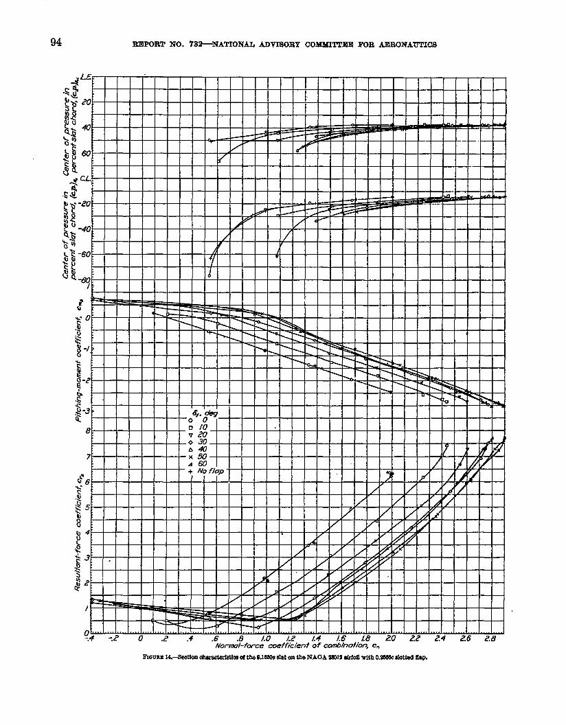
94 mmom NO. 732-NATIONAL mvrsmy commmm mB mRONAUTICS
Normd-fme coefficient of .canbInfftbn, c=
mmm M.—aectkmokuacMWm clthe OJ660ctit onthe NACIA=12 atrfoiltith O,W alotfsd @

PRESSURE DISTRIBUTION OVER NACA 28012 AIRFOIL WtTH FIXED SLOT AND SLOTTED I?IAP 95 .
0 I 2 3 45 67 .“\ 1\
Scale of vecfors @osed m c=) ‘%--_---j
22e\\a;6 “-.==------- -
--- --
+-. —
~. ------ J
/“/
f .,
—.
—
Fmum15.–VeotmtelroprcsentatbncJrmltentfmm ccdh?lent oftkeO.105.ksIat on the NACA ZlOIZnkfotlwith the02606cdottedflu%

96 ~POILT NO. 782—NATIONAL ADVtiQRY COMMIl”l’EE FOR AERONAUTICS
Nod-force mefficieni of cmibinafim, C=
Fmum lU.—&otkmoknctwlstlcaof tbeO.ZMOcs!ottcdftsPon thaNAOA 23012slrfoitwith tha &d slot.
PRESSURE DIST=UTION OVEB NACA .23012 AIEFOIL WITH ~ SLOT AND SL0TT13D FLAP 97
slotted flap (reference 7); and because the normal-force coefficients remain approximatdy the same onboth airfoils for a given fmgIe of attack, the center ofpressure moves rearward. No quantitative campmisortof pitching-moment coeflkients with force-twt resultsis made because the chord forces of flap and airfoiIhave been negkcted in this report; however, the valuwof c. obtbed by the two methods show reasonableagreement. The angle of attack for the EMI is slightlylower for the pressure-distribution tests, but no etlortwas made to obtain absolute valuea because the sameq~ent had been reported in reference I.
Figures 14 and 15 show the section characteristics ofthe dafi alone. The resultant-force coefEcient for theslat tested is much higher than that reported for theHandIey Page slat (references 2 and 4). The forces,however, act in the same direction and from approxi-matdy the same point. The maximum resuhsmt forceacts forward along a line that makes an angIe of ap-proximately 47° with the chord line and intersects it atthe 0.40 c. point, F~a 15 should be useful in thedesign of sIat supports.
A comparison of the section charaotezjst.ics of theflap aIone (&: 16) shows that the loads on the flapbuild up more slowIy than do the loads on tie mmbina-tion, except in the normal-force-coefficient range below1 with flap deflections greater than 30°. A comparisonof the section characteristics of the flap alone on theslotted airfoil @g. 16) with the section characteristicof the flap alone on a plain airfoil (reference 7) showsthe flap loads and moments to be little affected by theaddition of the leading-dge slot. Inasmuch as theloads on the &p in combination with a slotted airfoiIare approximately the same as the loads on the flap incombination with a lain airfoil, no chord-force co-eflicient.s are given. $ he chord-force coeflicienta re-ported in reference 7 shouId be applicable.
CONCLUSIONS
The peak pressures at tie nose of the slat were veryhigh in the range of angIe of attack where slots areUsefd.
The forces on the slat were smaUerthan the forces onthe same portion of a pkir.1airfQflat low angles!of attackbut budt up ta very high values above the stalJof the _plain airfoil. These forces were much higher thanpreviowdy pubIished Ioads on HandIey Page slats.
The loads on the flap on the sIotted airfoiI were ap-proximately tie same as the loads on a flap on a plainairfoil; therefore, any conventional ffap should showlittle chmge in load if a similar leading-edge slot were ._added to the oombinat.ion.
Lmc+mm MEMOEIAL Amomumcu hBOmTOIiY,
NAmONAL ADVISORY COMMITTEE FOB AERONAUTICS,
LNGLEY FIELD, VA., Jdy W, 1941.
REFERENCES
1. Bamber, M. T.: Wind-TunneI ‘I%sta of Se~eraI Forms ofFii Wig Slot in Combination with a SlottedFIapon anN. A. C. A. 23012 Airfoil. ‘1?.N. No. 702, NAG~ 1989.
2. Jacolm, E@man N.: Prwwre Distrfbutfon- on a SIottedR. A. F. 31 AirfoiI in the Variable Density Wind TunneLT. N. NO. 308, NAC&1929.
8. Cauvain, William E.: Wiid-Tunnel Teats of a Clark Y Wiigwith %laxw$dl” I.eadin&Edge ~OtS. T. N. No. 598,NACA, 1937.
4. Ormerod, A.: Slotted R. A. F. 34 Bridal FfgMer.-Meamra-ment of Forces on Slat in Flight. R. & M. No. 1477,British A. IL C., 1932.
5. V%nzinger, Carl J., and Harris, Thomas L: Wind-TunnelInwsatigation of an N. A. G. A. 23012 Airfoil with VariousArrangement of Slotted Flaps. Rep. No. 664, NACA,1939.
6. Pinkerton, Robert M.: The Variation with ReynoIds Numberof Pressure Distribution over an AirfoiI Seution. Rep.No. 613, NACA, 193S.
7. Wenzinger, Cad J., and DeIano, James B.: Presmre Dis-tribution over an N. A. C. A 23012 Airfoil with a SIottgdand a Plain Flap. Rep. No. 633, NACA, 193S.
8. Wenzinger, Cari J., and Ragallo, Francis M.: IMsurd ofAir-Load Data on Slats and FIaPs. T. N. No. 690,NACA, 1939.
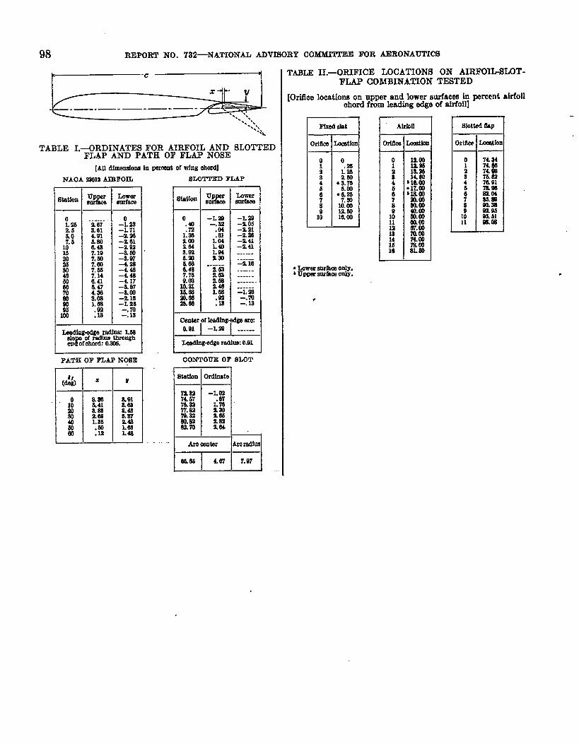
98 REPo~ NO. 732—NATION& ADTTf30RY CObfbfMTEE FOR AERONAmICS
TABLE H.-ORIFICE LOCATIONS ON AIRl?fXL-SLOT-FLAP COMBINATION TESTED
.—. .— -—.—-—-
W
TABLE I.-ORDINATES FOR AIRFOIL AND SLOTTEDFLAP AND PATE OF FLAP NOSE
[Ori5ce locations on upper and lower wfaces ~ w~cnt aiflollahord from Imding edge of airfoil]
AlrbIlFfxed .sht I Blotted&p
)rlflu)Ima
[AU dimemionn h Pm’mntof wtng ohord]
BLOTTED FLAPNAOA .2’W2 AIWOIL
L=mer
-L a-z 0s-% 21-2.w–z.u-z 41-----......-!216
oL 232.5b.o7.5
10
;
E%
00
E90
z
......Z 67a.614.91&!m6.487.197.bo7.007.M7.140.416.474.30.Kg
.9a
.18
-!.B-L 71-9.!M-% 61-% 92-a 50–8.974s-440~~ #
-a. 07-&W-216-L~a
Z la
I
—● ✍ mrracaonly.*upper .snrfamonly.
-------1. ‘as-. m-.la
L4dingage rsdhx 1J8do of radius throngh
ren Ofohord:O.sm.
PATH OF FLAP NOSE 00NTOUR OF SLOT
==F=lr 1“# naa -L M7km .07m.aa?7.a2 k!!‘nal 965al.w %Ue2m a64L
o
3ao4050W
:A
&a!ada1.ab.50.M
aelama.4b&wauLb3L&