report-multi point fuel injection-mpfi
TRANSCRIPT
MPFI
CONTENTS
INTRODUCTION 3
MAIN COMPONENTS OF MPFI4
AIR INTAKE SYSTEM 5 FUEL DELIVERY SYSTEM
6
ELECTRONIC CONTROL SYSTEM8
WORKING OF MPFI11
SENSORS USED IN MPFI12
ADVANTAGES OF MPFI14
CONCLUSION 15
REFRENCES15
1
MPFI
1. INTRODUCTION
Petrol vehicles uses device called carburetor for supplying the air
fuel mixture in correct ratio to cylinders in all rpm ranges. due to
construction of the carburetor is relatively simple, it has been used almost
exclusively on gasoline engines in the past. However in response to recent
demands for cleaner exhaust emission, more economical fuel consumption,
improved drivability, etc., the carburetor now must be equipped with
various compensating devices, making it more complex system.
So In place of the carburetor, therefore, the MPFI
(multi point fuel injection) system is used, assuring proper air fuel ratio to
the engine by electrically injecting fuel in accordance with various driving
conditions.
MPFI system injects fuel into individual cylinders, based on
commands from the ‘on board engine management system computer’ –
2
MPFI
popularly known as the Engine Control Unit/ECU. These techniques result
not only in better ‘power balance’ amongst the cylinders but also in higher
output from each one of them, along with faster throttle response. The
electronic fuel injection system supplies the combustion chambers with
air/fuel mixture of optimized ratio under widely varying driving
conditions.
2. MAIN COMPONENTS OF MPFI SYSTEM
This system has four major components they are:
a) Air intake system
b) Fuel delivery system
c) Electronic control system
2.1. Air intake system
. The air (corresponding to the throttle valve opening) is filtered by the air
cleaner, passes through the throttle body, and is distributed by the intake
manifold and finally drawn into each combustion chamber. When the lAC
valve is opened according to the signal from ECM, the air bypasses
the1hrottle valve through bypass passage and is finally drawn into the
intake manifold .
a. Throttle body
3
MPFI
. The throttle body consists of the main bore, air bypass passage and the
following parts. Throttle valve, which is interlocked with the accelerator
pedal and controls the amount of the intake air. TP sensor which detects
the throttle valve opening and sends a signal to ECM. lAC valve, which
supplies the bypass, air depending on Engine condition.
b. Idle air control valve
The lAC valve controls opening of the bypass air passage. The air bypasses
the throttle valve through bypass passage and is finally drawn into the
intake manifold. Opening and closing of the valve itself is determined by
operation of the magnet, which is connected to it. The magnet operates
according to electric current from ECM.
2.2. Fuel delivery system
The fuel in the fuel tank is pumped up by the fuel pump, filtered by fuel
filter and fed under pressure to each injector through the delivery 'pipe. As
the fuel pressure applied to the injector is always kept a certain amount
higher than the pressure in the intake manifold by the fuel pressure
regulator, the fuel is injected into the intake port of the cylinder head when
the injector opens according to the injection signal form ECM. The fuel
relieved by the fuel pressure regulator return through the fuel return to the
fuel tank.
a. Fuel pump
The electrical fuel pump located on the fuel tank consists of armature,
magnet, impeller, brush, check valve etc.The ECM controls its operation.
When the power is supplied to the fuel pump, the motor in the pump runs
4
MPFI
and so does the impeller. This causes a pressure difference to occur
between both sides of the impeller, as there are many grooves around it.
Then the fuel is drawn through the inlet port, and with its pressure
increases,
It is discharged through the outlet port, The fuel pump also has a check
valve to keep some pressure in the fuel feed line even when the fuel pump
is stopped.
b. Pressure regulator system
The fuel pressure regulator is diaphragm operated relief valve consisting of
diaphragm, spring and valve. It keeps the fuel pressure applied to the
injector 2.9Kglcm^2 higher than intake manifold at all times, The pressure
applied to the upper chamber of the fuel pressure regulator intake manifold
pressure and that to the lower chamber is fuel pressure. When the fuel
pressure rises more than 2,9Kg/cm2 higher than the intake manifold
pressure, the fuel pushes the valve in the regulator open and excess fuel
return to the fuel tank through return line.
c. Injector
Each cylinder has one injector. Which is installed between the intake
manifold delivery pipe. It is an electromagnetic type injection nozzle,
which injects fuel into the intake port of the cylinder head according to the
signal from ECM. When the solenoid coil of the injector is energised by
ECM, it becomes an Electro magnet and attracts the plunger. At the same
time, the ball valve which is incorporated with the plunger opens and the
5
MPFI
injector which is under the fuel pressure injects fuel. As the lift stroke of
the ball valve of the injector is set constant, the amount of fuel injected at
one time is determined by the length of the time during which the solenoid
is energized
2.3. Electronic control system
The electronic control system consist of various sensors which detect
the state of engine and driving conditions, ECM which controls various
devices according to the signals from the sensors and Various controlled
devices. The systems are
Fuel injection control system
Idle speed control system
Fuel pump control system,
Ignition control system,
Radiator fan control system,
Fuel injection control system
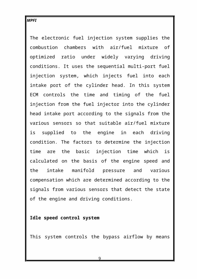
The electronic fuel injection system supplies the combustion chambers
with air/fuel mixture of optimized ratio under widely varying driving
conditions. It uses the sequential multi-port fuel injection system, which
injects fuel into each intake port of the cylinder head. In this system ECM
6
MPFI
controls the time and timing of the fuel injection from the fuel injector into
the cylinder head intake port according to the signals from the various
sensors so that suitable air/fuel mixture is supplied to the engine in each
driving condition. The factors to determine the injection time are the basic
injection time which is calculated on the basis of the engine speed and the
intake manifold pressure and various compensation which are determined
according to the signals from various sensors that detect the state of the
engine and driving conditions.
Idle speed control system
This system controls the bypass airflow by means of ECM & lAC valve for
the following purposes. To keep the engine idle speed as specified at all
times. The engine idle speed can vary due to load applied to engine, to
improve starting performance of the engine to compensate air fuel mixture
ratio when -decelerating, to improve drivability while engine is warmed
up. lAC valve operates according to duty signal sent from ECM. ECM
detects the engine condition by using the signals from various signals and
switches and controls the bypass airflow by changing lAC valve opening.
When the vehicle is at a stop, the throttle valve is at the idle position and
the engine is running, the engine speed is kept at a specified idle speed.
Fuel pump control system
ECM controls ON/OFF operation of the fuel pump by turning it ON, the
fuel pump relay under any of the conditions. For two seconds after ignition
switch ON. While cranking engine (while engine start signal is inputted to
ECM). While crankshaft position sensor or camshaft - position sensor
7
MPFI
signal is inputted to ECM.
Ignition control system
This system controls electronically the time of electric current flow to
ignition primary coil as well as ignition timing. ECM judges the engine
and vehicle conditions by using signals from various sensors, selects the
most suitable electric current flow time and ignition timing for that
engine and vehicle conditions from among those Prestored in its memory
and sends an ignition signal to the igniter in ignition coil assembly.
Controls of this system include three different types as follows. Ignition
timing control at engine start, ignition timing control after engine start,
electric current flow time control.
Radiator fan control system
This system controls operation (ON/OFF) of the radiator fan motor.
Radiator fan motor is turned ON and OFF by its relay when ECM controls.
Radiator fan motor turned ON at below 98°C and OFF at below 93°C
a. Engine Control Module (ECM)
ECM is installed to the underside of the instrument panel at the passenger's
seat side. ECM is a precision unit consisting of microcomputer,
analogue/digital converter input/output unit etc. It is an essential part of the
electronic control system for its functions include not only such a major
function as to control fuel injector, lAC valve, fuel pump relay, etc. But,
8
MPFI
also on-board diagnostic system (self-diagnosis function) and fail-safe
function.
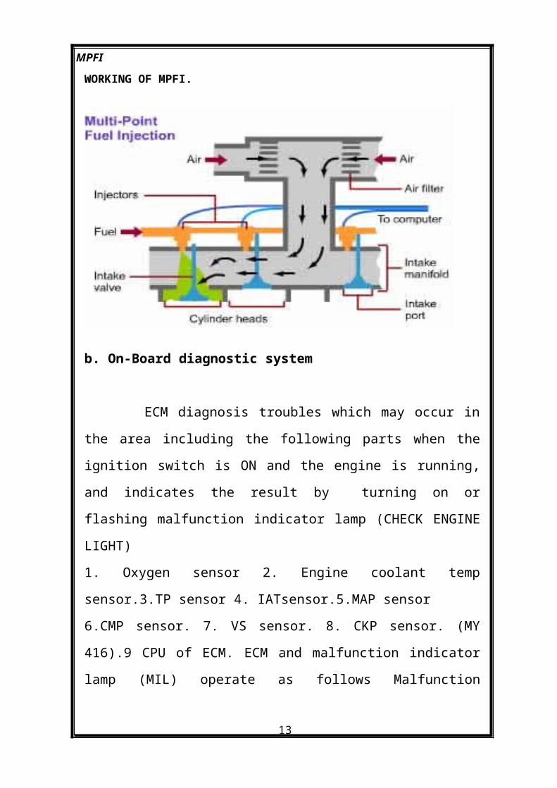
WORKING OF MPFI.
b. On-Board diagnostic system
ECM diagnosis troubles which may occur in the area including the
following parts when the ignition switch is ON and the engine is running,
and indicates the result by turning on or flashing malfunction indicator
lamp (CHECK ENGINE LIGHT)
1. Oxygen sensor 2. Engine coolant temp sensor.3.TP sensor 4.
9
MPFI
IATsensor.5.MAP sensor
6.CMP sensor. 7. VS sensor. 8. CKP sensor. (MY 416).9 CPU of ECM.
ECM and malfunction indicator lamp (MIL) operate as follows
Malfunction indicator lamp lights when the ignition switch is turned ON
but engine at stop with the diagnosis switch terminal ungrounded
regardless of the condition of electronic fuel injection system. This is only
to check the malfunction indicator lamp bulb and its circuit.If the above
areas of electronic fuel injection system; is free from any trouble after the
engine start while engine is running. Malfunction indicator lamp turns
OFF. When ECM detects a trouble which has occurred in the above areas,
it makes malfunction indicator lamp turn ON while the engine is running
to warn the driver of such occurrence of trouble and at the same time is
stores the trouble area in ECM back-up memory. The memory is kept as it
is even if the trouble was only temporary and disappeared immediately.
And it is not erased unless the power to ECM is shut off for specified time
60 sec. or longer. ECM also indicates trouble area in memory by means of
flashing of malfunction indicator lamp at the time of inspection.
. Fail- safe function
Even when a trouble has occurred in such area of electronic fuel
injection system that includes the following parts and a failure signal is
sent to ECM. control over the injector, idle air control valve and others is
maintained on the basis of the standard signals and/or CPU. This function
is called failsafe function. Thus with this function a certain level of engine
performance is available even when some failure occurs in such area and
disability in running is avoided.
10

MPFI
4. SENSORS USED IN MPFI.
1 Manifold absolute pressure (MAP) sensor
This sensor senses pressure change in the intake manifold and converts it
into voltage Change. It consists of a semi-conductor type pressure
converting element, which converts a pressure change into an electrical
change and, an electronic circuit which amplifies and corrects the electric
change. The ECM sends a 5-volt reference voltage to the pressure sensor.
As the manifold pressure changes, the electrical resistance of the sensor
also changes By monitoring the sensor output voltage ,ECM knows the
manifold pressure, ECM uses the voltage signal from the pressure sensor
as one of the signals to control fuel injector.
2. Throttle position sensor
The throttle position sensor is connected to the throttle valve shaft on the
throttle body, and detects throttle valve opening, the throttle opening is
detected by the potentiometer. A 5-volt reference Voltage is applied to the
sensor from ECM and as Brush moves over the print resistance according
to the throttle valve opening, the output voltage varies accordingly. By
monitoring sensor output voltage, ECM detects the throttle valve opening.
ECM uses the signal from TP sensor as one of the signals to control
various devices.
3 Intake air temperature sensor
Located on the air cleaner outlet hose, this sensor constantly measures the
Temperature of the air entering there and converts a change in the air
11
MPFI
temperature
Into that in resistance through its thermistor. That is, as is temperature
lowers, resistance increases and as it rises, resistance decreases. As air
density of the intake air varies with Variation in temperature, ECM, by
monitoring the resistance, adjusts the amount of fuel injection according to
the air temperature
4 Engine coolant temperature sensor
Incorporated with coolant temperature. Gauge and installed to
thermostat case, this sensor measures the temperature of the engine coolant
and converts its change into that in resistance through the thermistor like
the air temperature sensor, by monitoring the resistance of the coolant
temperature sensor, ECM detects the engine coolant temperature and that
affects most systems under the control of ECM.
5 Oxygen sensor
The oxygen sensor is installed on the exhaust manifold to detect the
concentration of oxygen in the exhaust gases. in order of engines equipped
with the three- way catalytic converter to achieve their best exhaust
emission purification performance, it is necessary for the air-fuel ratio to
be kept within a narrow range near the theoretical air-fuel ratio The
oxygen sensor senses whether the air-fuel ratio is richer on leaner than the
theoretical air-fuel ratio, The oxygen sensor is located in the exhaust
manifold and consists of an element made of zirconium dioxide (zrO2, a
kind of ceramic material) This element is coated on both inside and outside
12
MPFI
with a thin layer of platinum. Atmospheric air is introduced into the inside
of the sensor, and outside of the sensor is exposed to the exhaust gases. If
the Oxygen concentration on the inside surface of the zirconium element
differs greatly from that on the outside surface at high temperatures, the
zirconium element generate a voltage when the air-fuel mixture is lean
there is lot of oxygen in the exhaust gas, so there is a little difference
between oxygen concentration inside and outside the sensor element. Thus
the voltage generated by the zirconium element is low if the air-fuel
mixture is rich; the oxygen in the exhaust has almost disappears. This
creates a large difference in the oxygen concentrations inside and outside
the sensor and voltage generated by the zirconium element is large. The
ECM uses this signal to increase or reduce the injection volume to keep the
air-fuel ratio at an even value near the stoichiometric air-fuel ratio.
6 Vehicle speed sensor
The vehicle speed sensor, located on the transmission gearbox or
speedometer, Generates a signal in proportion to the vehicle speed.
Receiving this signal, the speedometer uses it for operation of its indicator
and also converts it into to the ON/OFF signal by doubling the cycle. This
signal is sent to ECM where it is used as one of the signals to control
various devices.
7. Camshaft position sensor
The sensor is mounted on the sensor case (distributor less ignition case) on
tile camshaft let side for distributor less ignition vehicle and other vehicles
on the distributor. The signal rotor is press-fitted onto the camshaft
13
MPFI
(distributor less ignition vehicle) and other vehicles on the distributor shaft.
As the sensor has a built-in hall element and a waveform forming circuit, it
converts changes in the magnetic flux caused by rotation of the signal rotor
into electric pulse signals, Using this signal and the signal from the CKP
sensor (if equipped), ECM identifies the cylinder whose piston is in the
compression stroke.
8. Crank shaft position sensor
The sensor consists of magnet and coil. It is mounted on oil pan with
specified air gap between the sensor core end and crankshaft timing belt
pulley tooth. As the crankshaft turns, AC voltage is generated in the
sensor. ECM uses this signal as: Engine speed, Cylinder identification.
5. ADVANTAGES OF MPFI
1) More uniform A/F mixture will be supplied to each cylinder; hence the
difference in power developed in each cylinder is minimum. Vibration
from the engine equipped with this system is less, due to this the life of
engine components is improved.
(2) No need to crank the engine twice or thrice in case of cold starting as
happens in the carburetor system.
(3) Immediate response, in case of sudden acceleration / deceleration.
(4) Since the engine is controlled by ECM* (Engine Control Module),
14
MPFI
more accurate amount of A/F mixture will be supplied and as a result
complete combustion will take place. This leads to effective utilization of
fuel supplied and hence low emission level.
(5) The mileage of the vehicle will be improved.
6. CONCLUSION
Almost all vehicles in India are changing to the mpfi because of law
emissions, improved mileage and drivability since the engine is
controlled by micro computer more accurate amount of a/f mixture will
be supplied and as a result complete combustion will take place. this
leads to effective utilization of fuel supplied and hence low emission
level. it reduces wastage of fuel by the use of sensors and other control
systems
7. REFERENCES
Automotive technology –Jack
erjavec
Automobile engineering – Anil
chhakra
15
MPFI
Automobile engineering-V.Ganesh
www.howstuffworks .com
www.indiacar.com
16