report for: concrete reinforcing steel institute
TRANSCRIPT
Assessment of GFRP Properties: A Literature Review
by
David Trejo, PhD
Report for: Concrete Reinforcing Steel Institute
933 North Plum Grove Road
Schaumburg, IL 60173-4758
Original Submittal: October 19, 2018
Revised Submittal 1: January 21, 2019
Revised Submittal 2: June 19, 2019

ii
Executive Summary
There has been significant development in the design and use of GFRP reinforcing bars. This
report provides an overview of the literature on the properties, characteristics, and performance of
GFRP bars. This literature review indicates that when compared with steel reinforcement, GFRP
reinforcing bars exhibit lower modulus of elasticity values, lower ductility, and lower bar-concrete
bond. The literature also indicates that structures reinforced with GFRP can exhibit larger
deflections and larger crack widths. GFRP bars are also lighter than steel bars and are non-
conductive and non-magnetic, which provide some potential benefits for specific situations.
However, one characteristic that has not achieved consensus in the engineering community is the
durability of GFRP when embedded in concrete. In the large majority of cases concrete has a high
relative humidity within its pore system and this moisture consists of a high pH solution. When
GFRP reinforcing bars are embedded in concrete, the composite surrounding the glass fibers is
supposed to protect the glass fibers from potential deterioration. However, the high pH pore
solution can penetrate this composite material. As the high pH pore solution penetrates the
composite it eventually reaches the glass fiber and these fibers are susceptible to etching and
leaching. This etching and leaching of the glass fibers in the GFRP can result in loss of bond
between the glass fibers and composite material or can result in weakening of the glass fibers. Both
debonding and loss of glass fiber strength result in loss of strength in GFRP reinforcing bars. Loss
of strength in GFRP reinforcing bars has been reported throughout the literature. Unlike steel
reinforcement, which when corroded exhibits signs of degradation (e.g., rust stains or concrete
delamination), when GFRP degrades there are no visual signs of this degradation.
Some recent research indicates that GFRP reinforcing bars embedded in field structures do not
exhibit degradation or loss of strength. However, these research studies contained no direct
measurements of the residual tensile strength of GFRP reinforcing bars. Although indirect
measures of GFRP degradation are improving, direct measurements of GFRP reinforcement
degradation provide a clear and unambiguous measure of performance. Because the literature
indicates that GFRP reinforcing bars do lose strength with time and because degrading GFRP bars
provide no visible warning of this degradation, the engineering community must move forward in
using this reinforcement with caution.

ii
Table of Contents
1. Introduction and Objectives ....................................................................................................1
2. Literature Review....................................................................................................................1
2.1. History .............................................................................................................................2
2.2. Fabrication of GFRP Reinforcement and Potential Challenges ......................................2
2.3. GFRP Manufacturers .......................................................................................................3
2.4. GFRP Characteristics: Manufacturer Reported Characteristics ......................................4
2.5. Properties of GFRP Reinforcement .................................................................................5
2.6. Longer-term GFRP Performance .....................................................................................6
2.7. Mechanisms and Modeling Degradation in GFRP Reinforcement ...............................12
3. Standardized Durability Tests for GFRP Reinforcement .....................................................18
4. General Design Methodology and Challenges for GFRP-reinforced Concrete Members ...20
5. Summary ...............................................................................................................................23
6. Appendix ...............................................................................................................................27
7. References .............................................................................................................................31

1
1. Introduction and Objectives
Significant efforts have been and are currently underway to replace conventional construction
materials (e.g., steel and concrete) with composite materials. Although these composite products
do have several positive attributes, there is considerable concern regarding the long-term
performance of these materials. Long-term performance is a legitimate concern as infrastructure
systems are generally designed and constructed to serve the public for 75 to 125 years, depending
on the type of infrastructure system. Trejo and Reinschmidt (2007) proposed an economic analysis
method to assess the value of using alternative materials and concluded that some materials can
provide economic benefits if these materials can provide long-term performance. Alternatively,
the authors reported that some materials do not provide value when they are not durable and do
not provide long-term durability. Understanding the durability and long-term performance
characteristics of a material, especially a newer material being introduced for infrastructure
systems, is essential as the cost of designing and constructing these infrastructure systems is
significant. This paper will provide an overview of the literature and challenges associated with
the implementation of composites, specifically glass fiber reinforced polymer (GFRP) reinforcing
bars for concrete reinforcement, into the construction industry.
2. Literature Review
The use of composites in the construction industry has been relatively limited. However, in the
1990s significant research was initiated to assess if GFRP reinforcing bars could be used as an
alternate material for steel reinforcement in concrete. Because of the low modulus and low ductility
of GFRP, significant efforts were expended in developing new design methodologies for these
materials and design methodologies are now available (ACI 440.1R). One major claim of
producers and some researchers is that composites do not corrode and therefore, reinforced
concrete structures made with these materials would have longer service life than a structure made
with conventional steel reinforcement. This literature review will clearly show that GFRP bars do
indeed degrade, resulting in a reduction in tensile capacity. This degradation of the GFRP is
reportedly dependent on the exposure conditions of the concrete. This section will provide a review
of literature, providing a brief history of FRP, a brief overview of the fabrication process for GFRP,

2
and will provide an overview of the properties, with emphasis on the durability characteristics of
GFRP reinforcing bars.
2.1. History
One relatively new product introduced to the engineering and construction market is fiber
reinforced polymers (FRP) and specifically GFRP for concrete reinforcement. Although not new,
the introduction of glass fibers and composites to the construction industry has been relatively
recent. The patent for “glass wool” was granted in 1933 and fiberglas (this was the original spelling
in the patent) was patented in 1936. Significant efforts were expended in developing prototype
automobiles and aircraft components soon after the patent was assigned and the use of composites
in these industries has been significant. The first introduction of FRP as a construction material for
concrete applications, as published in the American Concrete Institute’s (ACI) journal, was in
1981 (Fardis and Khalili 1981). The authors proposed using FRP for stay-in-place concrete forms.
No other publications on FRP were published in the ACI journals in the 1980s. However, in 1991,
Bunea proposed using GFRP as a replacement for steel reinforcement but focused on using the
material for lunar settlements or habitats. The number of published papers on FRP increased
significantly in the 1990’s and over 200 manuscripts were published in the ACI journals. Because
of GFRP’s low modulus and low ductility many of these publications focused on developing
methodologies for the design of GFRP-reinforced concrete members (Brown and Bartholomew
1993, Rahman et al. 1993, Eshani et al. 1993, Tottori and Wakui 1993). Many of the publications
claimed that GFRP was more durable and free from deterioration yet very little research had been
performed on assessing the longer-term performance and potential mechanisms of deterioration of
GFRP reinforcement in concrete systems. Although research has been performed since, more
research is needed to assess the long-term characteristics and performance of GFRP reinforcing
bars.
2.2. Fabrication of GFRP Reinforcement and Potential Challenges
GFRP reinforcement consists of continuous glass fiber filaments embedded in a composite matrix,
typically polyester or vinylester. A schematic of a typical cross sectional view of a bar is shown in
Figure 1. The glass filaments, or roving, provides the strength while the polyester or vinylester
composite binds these fibers together to provide composite action within the bar. The vinylester

3
or polyester composite material is also
supposed to protect the glass fibers from
deteriorating by removing and protecting
these fibers from solutions that may be
aggressive or corrosion to these fibers.
The composite action, i.e., the bond
between the polyester or vinylester and
glass fibers, is critical to the long-term
performance of the FRP system.
The general process of producing GFRP
reinforcing bars is to pull the filaments
through a resin bath, preform the bar, then pass the product into a heated die where the resin
polymerizes to form the final product. Busel (2012) reported that most FRP products are
manufactured with the process shown in Figure 2. Because the glass filaments are the load-bearing
components and these glass filaments can be susceptible to degradation, it is critical that these
filaments or fibers are embedded within the composite matrix. The composite matrix can slow the
ingress of water or aggressive ions that can degrade the fibers. However, even if the fibers are
embedded in the composite matrix, moisture or other aggressive ions can migrate into the
composite matrix, reducing the bond between the glass fiber and composite matrix, and/or
reducing the load carrying capacity of the fibers and eventually the FRP bar.
Figure 2 General manufacturing process of FRP reinforcing bars (after Busel 2012).
2.3. GFRP Manufacturers
Several manufacturers produce GFRP in North America. Table 1 provides a summary of
manufacturers that have been identified. Contact information for each producer is also provided.
Figure 1 Typical cross-section of GFRP reinforcing bar (not to scale).

4
Table 1 List of Manufacturers of GFRP Reinforcement in North America 1. Marshall Composite Technologies, LLC
2873 22nd Street SE Salem, Oregon 97302
2. TUF-BAR Inc. #900 111 2nd Avenue NE St Petersburg, FL 33701
3. TUF-BAR Inc. 5522 36th Street NW Edmonton, Alberta Canada, T6B 3P3
4. TUF-BAR Canada Inc. 7 Erin Park Drive Erin, Ontario Canada N0B 1T0
5. Hughes Brothers, Inc. 210 N. 13th Street Seward NE 68434
6. Pultrall 700 9th Street North Thetford Mines (Quebec) Canada G6G 6Z5
7. VROD Canada 53 Woodstream Blvd. Unit 7A Woodbridge, ON L4L 7Y8
8. Kodiak Fiberglass Rebar Katy, Texas 77450
9. American Fiberglass Rebar 1191 Center Point Drive Henderson, NV 89074
10. B&B FRP Manufacturing 40 Millwick Drive, Unit 9 Toronto, Ontario Canada M9L 1Y3
11. Nycon Headquarters 300 Ben Fairless Drive Fairless Hills, PA 19030 USA
2.4. GFRP Characteristics: Manufacturer Reported Characteristics
Some manufacturers of GFRP reinforcement report that GFRP reinforcing bars are impervious to
chloride ions and low pH chemical attack, are not susceptible to corrosion, have tensile strengths
greater than steel, have modulus of elasticity values of 5800 and 8700 ksi, are one-quarter the

5
weight of steel reinforcing bars, are transparent to magnetic fields and radio waves, are electrically
non-conductive, and are thermally non-conductive. The magnetic transparency and low
conductivity GFRP bar characteristics are advantageous in pavement applications where
conductive steel reinforcement can alter magnetic signals embedded in the pavement. The low
weight has been reported to be beneficial during construction. Design methodologies addressing
the higher tensile strengths and lower modulus characteristics have been implemented and with
the exception of later-age tensile strengths, are relatively accepted. The claims that the GFRP bars
are impervious to chloride ions and have no susceptibility to corrosion are somewhat controversial
and significant research has been performed in these areas. Although GFRP does not undergo
classical corrosion, the literature contains many examples where GFRP bars exhibited
deterioration and loss of tensile strength. This literature will be reviewed and presented later.
2.5. Properties of GFRP Reinforcement
GFRP reinforcement exhibits different mechanical properties than steel reinforcement. Figure 3
shows a typical stress-strain plot of Grade 60 and Grade 80 steel reinforcing bars (meeting ASTM
A706 specifications) and a typical stress-strain plot for a new GFRP reinforcement. The GFRP
stress and strain data are reported values from a GFRP manufacturer. As can be seen, the modulus
of elasticity of the GFRP is significantly lower than that of the modulus of elasticity of the steel
reinforcement. Aguiniga (2003) reported that the modulus of GFRP is approximately 1/5 that of
steel. Note also from the figures that the ductility of the GFRP is significantly less than the ductility
of the steel reinforcement. The manufacturer reports that the guaranteed ultimate tensile strength
(GUTS) of the GFRP decreases with increasing diameter, ranging from 130 ksi to 60 ksi. As a
result of the difference in properties of GFRP reinforcing bars, modifications to the design of
GFRP-reinforced concrete had to be developed. The American Concrete Institute’s Committee
440 has taken the lead on developing these design methods. The general methodology of the design
process will be discussed later.
Aguiniga (2003) reported that GFRP reinforcing bars exhibit high transverse coefficient of
thermal expansion values. However, Schaefer (2002) conducted thermal expansion tests and
concluded that a concrete cover to bar diameter ratio of as low as 1.33 would not cause a typical
concrete bridge deck with 28-day compressive strength of approximately 5880 psi to crack due to

6
thermal expansion. Aiello (1999) also reported that thermal expansion of bars would not lead to
concrete cracking for concrete cover to bar diameters of 2 or more.
Figure 3 Stress strain relationship for different reinforcement types.
Aguiniga (2003) and later Al-Salloum and Almusallam (2007) reported that GFRP exhibits
significant creep. Youssef and Benmokrane (2011) reported that creep of GFRP bars was
dependent on fiber content and bar diameter and noted that GFRP bars that did exhibit creep
experience minimal loss in tensile strength. Aguiniga (2003) proposed a method for evaluating the
strains and curvatures of FRP reinforced concrete elements, accounting for creep of the GFRP
bars.
2.6. Longer-term GFRP Performance
Figure 3 showed a stress-strain plot for a new GFRP reinforcing bar. Because both composite and
glass materials have been reported to degrade when exposed to some environments and because
composites do absorb moisture, significant research has been performed to assess the time-variant
properties, e.g., the residual tensile strength of GFRP bars. Many researchers have reported
significant changes to the properties of GFRP reinforcing bars, mainly tensile strength, after
7
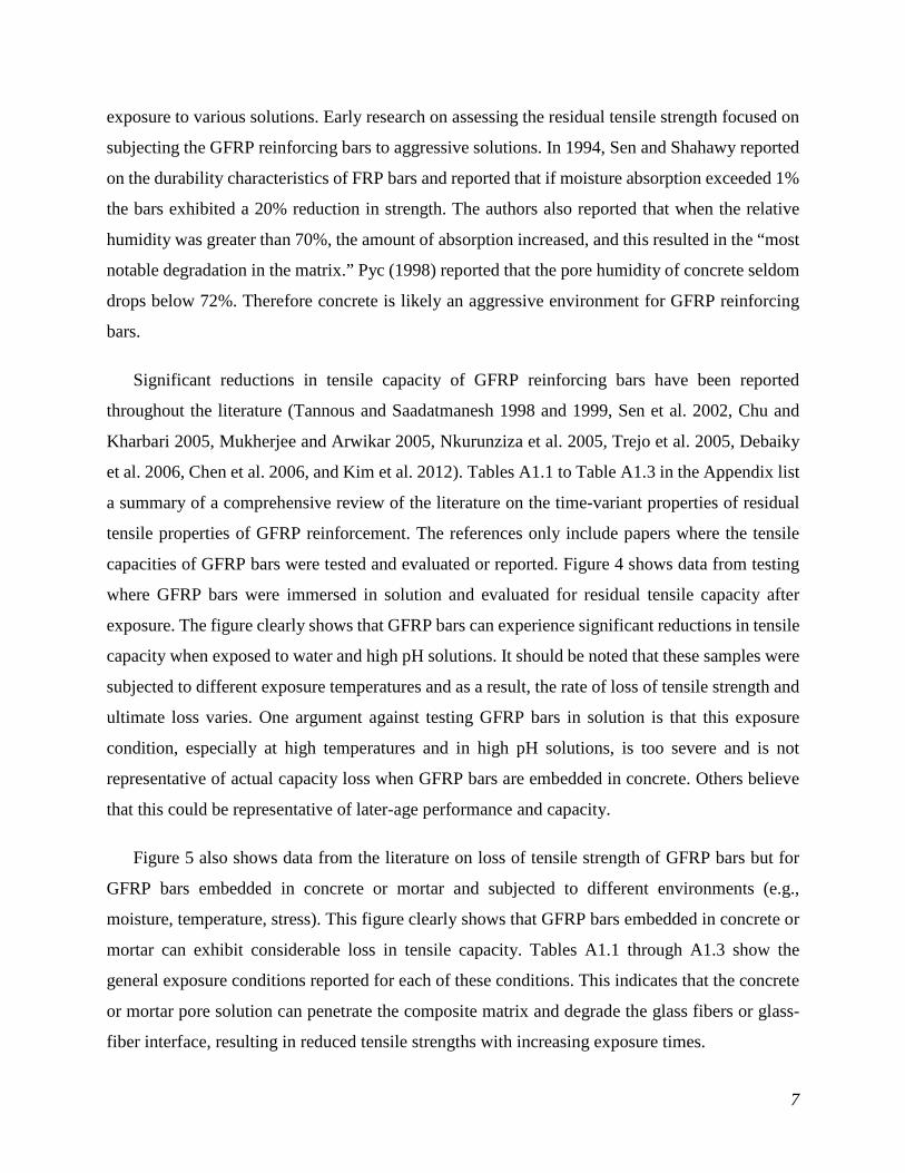
exposure to various solutions. Early research on assessing the residual tensile strength focused on
subjecting the GFRP reinforcing bars to aggressive solutions. In 1994, Sen and Shahawy reported
on the durability characteristics of FRP bars and reported that if moisture absorption exceeded 1%
the bars exhibited a 20% reduction in strength. The authors also reported that when the relative
humidity was greater than 70%, the amount of absorption increased, and this resulted in the “most
notable degradation in the matrix.” Pyc (1998) reported that the pore humidity of concrete seldom
drops below 72%. Therefore concrete is likely an aggressive environment for GFRP reinforcing
bars.
Significant reductions in tensile capacity of GFRP reinforcing bars have been reported
throughout the literature (Tannous and Saadatmanesh 1998 and 1999, Sen et al. 2002, Chu and
Kharbari 2005, Mukherjee and Arwikar 2005, Nkurunziza et al. 2005, Trejo et al. 2005, Debaiky
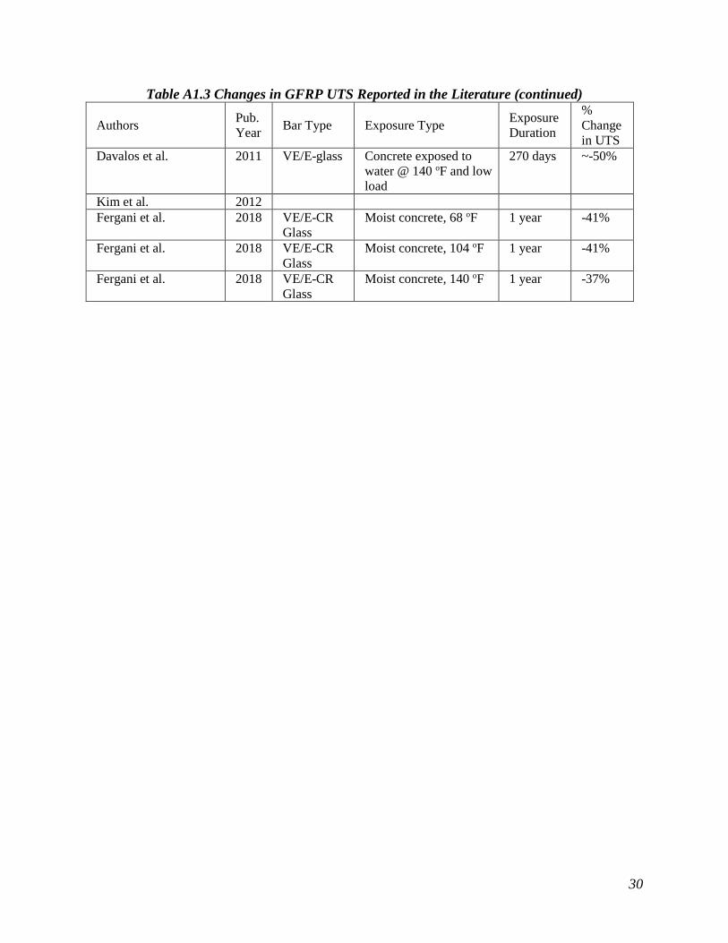
et al. 2006, Chen et al. 2006, and Kim et al. 2012). Tables A1.1 to Table A1.3 in the Appendix list
a summary of a comprehensive review of the literature on the time-variant properties of residual
tensile properties of GFRP reinforcement. The references only include papers where the tensile
capacities of GFRP bars were tested and evaluated or reported. Figure 4 shows data from testing
where GFRP bars were immersed in solution and evaluated for residual tensile capacity after
exposure. The figure clearly shows that GFRP bars can experience significant reductions in tensile
capacity when exposed to water and high pH solutions. It should be noted that these samples were
subjected to different exposure temperatures and as a result, the rate of loss of tensile strength and
ultimate loss varies. One argument against testing GFRP bars in solution is that this exposure
condition, especially at high temperatures and in high pH solutions, is too severe and is not
representative of actual capacity loss when GFRP bars are embedded in concrete. Others believe
that this could be representative of later-age performance and capacity.
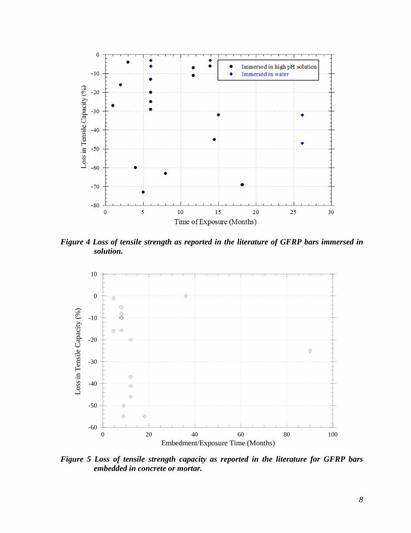
Figure 5 also shows data from the literature on loss of tensile strength of GFRP bars but for
GFRP bars embedded in concrete or mortar and subjected to different environments (e.g.,
moisture, temperature, stress). This figure clearly shows that GFRP bars embedded in concrete or
mortar can exhibit considerable loss in tensile capacity. Tables A1.1 through A1.3 show the
general exposure conditions reported for each of these conditions. This indicates that the concrete
or mortar pore solution can penetrate the composite matrix and degrade the glass fibers or glass-
fiber interface, resulting in reduced tensile strengths with increasing exposure times.
8
Figure 4 Loss of tensile strength as reported in the literature of GFRP bars immersed in solution.
-60
-50
-40
-30
-20
-10
0
10
0 20 40 60 80 100
Loss
in T
ensi
le C
apac
ity (%
)
Embedment/Exposure Time (Months) Figure 5 Loss of tensile strength capacity as reported in the literature for GFRP bars
embedded in concrete or mortar.
9
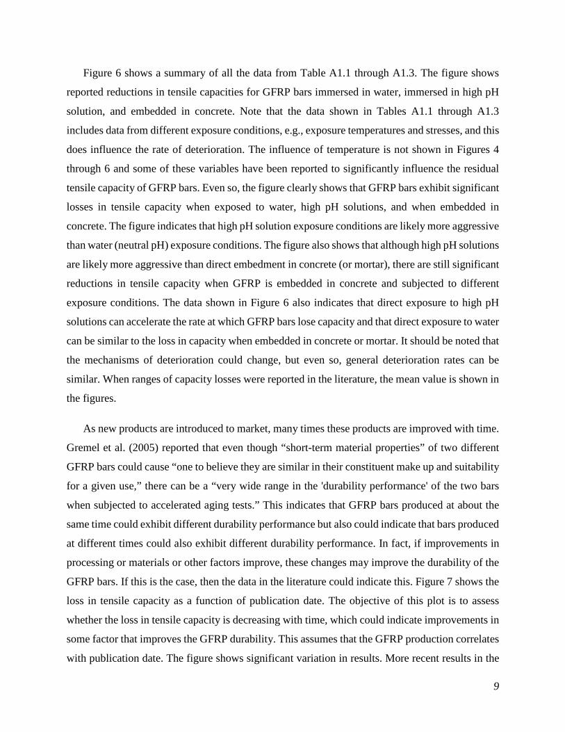
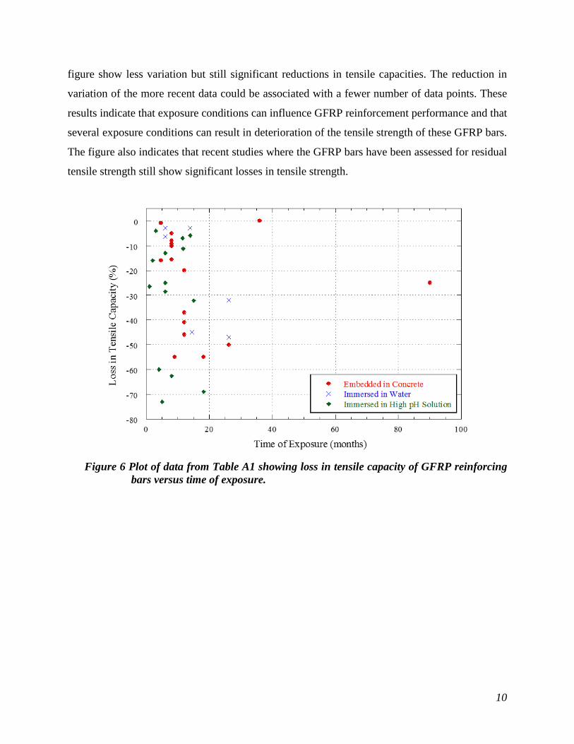
Figure 6 shows a summary of all the data from Table A1.1 through A1.3. The figure shows
reported reductions in tensile capacities for GFRP bars immersed in water, immersed in high pH
solution, and embedded in concrete. Note that the data shown in Tables A1.1 through A1.3
includes data from different exposure conditions, e.g., exposure temperatures and stresses, and this
does influence the rate of deterioration. The influence of temperature is not shown in Figures 4
through 6 and some of these variables have been reported to significantly influence the residual
tensile capacity of GFRP bars. Even so, the figure clearly shows that GFRP bars exhibit significant
losses in tensile capacity when exposed to water, high pH solutions, and when embedded in
concrete. The figure indicates that high pH solution exposure conditions are likely more aggressive
than water (neutral pH) exposure conditions. The figure also shows that although high pH solutions
are likely more aggressive than direct embedment in concrete (or mortar), there are still significant
reductions in tensile capacity when GFRP is embedded in concrete and subjected to different
exposure conditions. The data shown in Figure 6 also indicates that direct exposure to high pH
solutions can accelerate the rate at which GFRP bars lose capacity and that direct exposure to water
can be similar to the loss in capacity when embedded in concrete or mortar. It should be noted that
the mechanisms of deterioration could change, but even so, general deterioration rates can be
similar. When ranges of capacity losses were reported in the literature, the mean value is shown in
the figures.
As new products are introduced to market, many times these products are improved with time.
Gremel et al. (2005) reported that even though “short-term material properties” of two different
GFRP bars could cause “one to believe they are similar in their constituent make up and suitability
for a given use,” there can be a “very wide range in the 'durability performance' of the two bars
when subjected to accelerated aging tests.” This indicates that GFRP bars produced at about the
same time could exhibit different durability performance but also could indicate that bars produced
at different times could also exhibit different durability performance. In fact, if improvements in
processing or materials or other factors improve, these changes may improve the durability of the
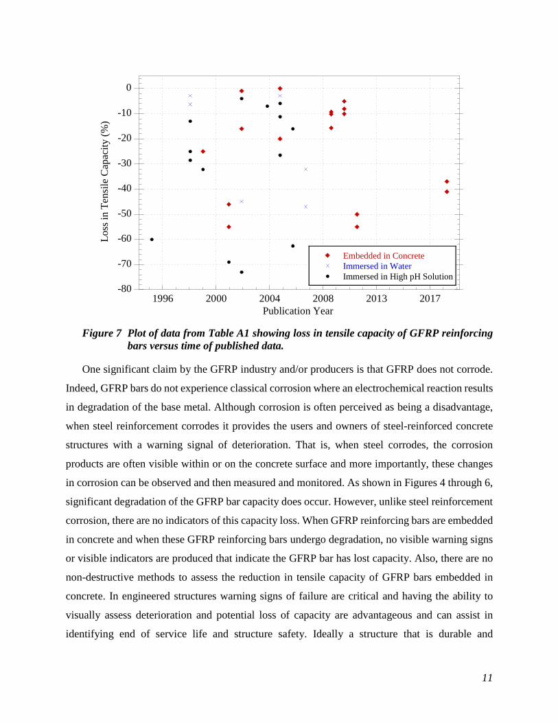
GFRP bars. If this is the case, then the data in the literature could indicate this. Figure 7 shows the
loss in tensile capacity as a function of publication date. The objective of this plot is to assess
whether the loss in tensile capacity is decreasing with time, which could indicate improvements in
some factor that improves the GFRP durability. This assumes that the GFRP production correlates
with publication date. The figure shows significant variation in results. More recent results in the
10
figure show less variation but still significant reductions in tensile capacities. The reduction in
variation of the more recent data could be associated with a fewer number of data points. These
results indicate that exposure conditions can influence GFRP reinforcement performance and that
several exposure conditions can result in deterioration of the tensile strength of these GFRP bars.
The figure also indicates that recent studies where the GFRP bars have been assessed for residual
tensile strength still show significant losses in tensile strength.
Figure 6 Plot of data from Table A1 showing loss in tensile capacity of GFRP reinforcing
bars versus time of exposure.
11
Figure 7 Plot of data from Table A1 showing loss in tensile capacity of GFRP reinforcing
bars versus time of published data.
One significant claim by the GFRP industry and/or producers is that GFRP does not corrode.
Indeed, GFRP bars do not experience classical corrosion where an electrochemical reaction results
in degradation of the base metal. Although corrosion is often perceived as being a disadvantage,
when steel reinforcement corrodes it provides the users and owners of steel-reinforced concrete
structures with a warning signal of deterioration. That is, when steel corrodes, the corrosion
products are often visible within or on the concrete surface and more importantly, these changes
in corrosion can be observed and then measured and monitored. As shown in Figures 4 through 6,
significant degradation of the GFRP bar capacity does occur. However, unlike steel reinforcement
corrosion, there are no indicators of this capacity loss. When GFRP reinforcing bars are embedded
in concrete and when these GFRP reinforcing bars undergo degradation, no visible warning signs
or visible indicators are produced that indicate the GFRP bar has lost capacity. Also, there are no
non-destructive methods to assess the reduction in tensile capacity of GFRP bars embedded in
concrete. In engineered structures warning signs of failure are critical and having the ability to
visually assess deterioration and potential loss of capacity are advantageous and can assist in
identifying end of service life and structure safety. Ideally a structure that is durable and
-80
-70
-60
-50
-40
-30
-20
-10
0
1996 2000 2004 2008 2013 2017
Embedded in ConcreteImmersed in WaterImmersed in High pH Solution
Loss
in T
ensi
le C
apac
ity (%
)
Publication Year
12
experiences no deterioration is preferred but when mechanisms of deterioration do occur, having
insight into this deterioration and the degree of damage is beneficial. Several researchers have
presented information on the potential mechanisms of deterioration of GFRP bars and these
mechanisms are presented next.
2.7. Mechanisms and Modeling Degradation in GFRP Reinforcement
Before addressing potential deterioration mechanisms, some definitions on terminology would be
beneficial. In general, the loss in tensile capacity is determined as the percent loss in capacity based
on the ultimate strength. The ultimate tensile strength, favg, is the average tensile capacity of a set
of reinforcing bars. However, favg does not consider potential deterioration of the GFRP bars and
the resulting reduction in tensile strength. Because of this, the ACI design guide for GFRP
reinforced structures (ACI Committee 440.1R 2006) requires that a reduction factor be applied to
the tensile strength of GFRP reinforcement. ACI 440.1R-06 reports that the design tensile strength,
ffu, should account for the environmental exposure conditions as follows:
fu E fuf C f ∗= (Eq. 1)
where CE is the environmental reduction factor and f*fu is the GUTS of the GFRP bar. The GUTS
is defined as the mean tensile strength of a sample of test specimens minus three standard
deviations (f*fu= favg-3×SD). Fergani et al. (2018) reported tensile strength data for GFRP bars and
reported a mean and COV of GFRP of 223.6 ksi and 1.8%, respectively. This would indicate that
the f*fu for those bars is 223.6–12=211.6 ksi. The value of CE is 0.7 for GFRP exposed to earth and
weather and 0.8 for GFRP not exposed to earth and weather. Using the information from Fergani
et al. (2018) and a reduction factor of 0.7 results in a design tensile strength of about 148 ksi, which
is approximately 66% of the original mean tensile strength. Using the same data and a reduction
factor of 0.8 would result in a design tensile strength of approximately 169 ksi, or almost 76% of
the original mean tensile strength. This indicates that the maximum allowable percent loss in
tensile strength for GFRP bars exposed to earth and weather would be 34% and for GFRP bars not
exposed to earth or weather 24%. Although the reduction factors (0.7 and 0.8) are reported to be
conservative estimates based on consensus of the ACI 440 committee and include the effects of
reasonable temperature increases inside the concrete, the data shown in Figures 4 through 6

13
indicate that a significant number of studies have reported significantly more capacity loss than
these limits. Several authors indicate that testing in high pH solution or saturated concrete is
aggressive and results from tests that include these conditions are not representative of the long-
term performance of GFRP reinforced concrete structures in the field. This argument has been
somewhat quieted with the recent development of ASTM and ACI documents that require these
exposures. However, care must be taken as very seldom is a designer able to control the exposure
conditions after the structure has been constructed. In addition, because loss in tensile capacity of
GFRP bars results in no visible indicators of degradation (e.g., corrosion surface stains) and non-
destructive methods for assessing this loss in capacity are not available, care must be taken when
using GFRP bars.
To better understand how GFRP bars deteriorate in a concrete environment, a description of
the reported mechanisms of deterioration will be provided. It has been reported that the pore
humidity in concrete seldom drops below 72% (Pyc 1998). When GFRP bars are exposed to this
humid, high pH environment (pore solution exhibits a pH of ~12.5 to 13), this pore solution can
migrate into the vinylester, polyester, or composite material that covers the glass fibers in the
GFRP bar (see Figure 1). With time, the depth of migration increases. When the pore solution
reaches the glass fiber-composite material interface, it is reported that the solution reacts with the
glass surface and deteriorates the bond between the composite and glass. This bond is critical to
the performance of the GFRP bar as this bond creates the composite action between the glass fibers
and composite material. Once this bond is destroyed, the fiber continues to degrade and the bar
losses capacity. Huang and Aboutaha (2010) reported that the composite matrix, the glass fiber,
and the interface between these two materials can be susceptible to attack, especially by alkali
attack in concrete.
Although one claim for using GFRP bars is the elimination of classic corrosion, GFRP bars do
exhibit loss in tensile capacity as a result of deterioration of the glass-composite bond, which
results in loss in capacity of the structure and can result in reduced service lives of GFRP-
reinforced structures. Huang and Aboutaha (2010) reported that degradation of the GFRP bars
begin when free hydroxyl ions (OH-) and water diffuse through the composite matrix of the bars
towards the glass fibers. The ester group undergoes hydrolysis and several studies indicate that
water can lead to swelling stresses, which leads to cracking and glass fiber-composite debonding

14
(Bank et al. 1995, fib 2007). The authors also reported that glass fibers are susceptible to leaching
and etching and this leaching and etching cause notching and embrittlement of the glass fibers,
which results in a reduction in capacity.
Katsuki and Uomoto (1995) reported that the residual tensile strength of GFRP bars after
exposure to alkaline solutions can be predicted. The authors hypothesized that GFRP bars degrade
due to the attack on the glass fibers at the fiber-composite material interface by the alkalis present
in the concrete pore solution. These authors observed and measured the depth of penetration of the
alkaline solution into GFRP bars using an electron probe microscope analyzer and using these data
proposed the following expression to estimate the depth of penetration of the pore solution:
Dctx 2= (Eq. 2)
where x, D, c, and t represent the depth of pore solution penetration from the surface of the bar
(cm), the diffusion coefficient for the pore solution into the FRP bar (cm2 h-1), the alkaline
concentration of the pore solution (mol/l), and the time of exposure (h), respectively. To predict
the residual tensile strength of GFRP bars the authors assumed the area where the alkalis penetrated
the GFRP bars have no strength; that is once the pore solution reaches the fiber the bond is
instantaneously destroyed. This general concept is shown in Figure 8 (R0-r1 is the depth of pore
solution penetration, x, in Eq. 2). As a result of this deterioration of the bond and glass fibers, the
authors proposed the following expression for the computation of the residual tensile strength:
0
2
0
21 σσ
−=
RDct
t
(Eq. 3)
where the terms are as described earlier and
σt, σo, and Ro are the tensile strength at any
given age (MPa), the tensile strength before
exposure (MPa), and the bar radius (cm),
respectively. The authors exposed GFRP bars
to a 1.0 mol/l aqueous solution of NaOH at
104 °F. The diffusion coefficient reported Figure 8 Graphic showing degradation area as
proposed by Katsuki and Uomoto (1995)
15
was 2.8x106 cm2/h and the results from the model predicted the loss of tensile capacity of the bars.
However, because the research was based on specimens exposed to high temperature, the
applicability to normal exposure conditions was unknown.
Other models have been developed but the model by Katsuki and Uomoto (1995) was reported
to provide a reasonable estimate of loss in capacity (Gurtin and Yatomi 1979, Carter and Kibler
1978). Aguiniga (2003) reported that the hypothesis that the glass fibers instantaneously lose all
capacity overestimates the loss of strength and reported a factor, λ, that compensated for the slower
rate of degradation and bond deterioration as follows:
𝜎𝜎𝑡𝑡 = 1 − �√2DλtR𝑜𝑜
�2𝜎𝜎0 (Eq. 4)
Although Aguiniga (2003) reported λ as a function of pore solution concentration and time, later
Aguiniga et al. (2004) reported that when λ was fit to the overall lowest observed residual tensile
strength, the value of λ was 0.006 when using exposure data up to 50 weeks. Using this
information, the authors concluded that an "environmental reduction factor of 0.7 for glass FRP
bars given in the ACI 440 design guidelines may be unconservative beyond approximately 7
years…" Wang et al. (2011) reported that the strength reduction of GFRP bars is dependent on
temperature and can be estimated as follows:
𝑆𝑆𝑆𝑆 = 114.4 − 15 × Log(t) for T = 68 oF (Eq. 5)
𝑆𝑆𝑆𝑆 = 113.5 − 19.2 × Log(t) for T = 140 oF (Eq. 6)
where t is time in days. The authors reported that for 100% RH and a temperature of 50 oF, the
strength retention of GFRP bars would be approximately 60% (40% loss of strength) after 20 years.
Chu and Karbhari (2005) reported that the percent retention, P, in tensile strength of GFRP could
be determined as follows:
𝑃𝑃 = −7.256 × 𝑙𝑙𝑙𝑙 (𝑡𝑡)+105.65 (Eq. 7)
where t is exposure time in weeks. Using this equation, Karbhari et al. (2007) reported that "the
environmental reduction factor of 0.7 recommended by the ACI 440 design guidelines (ACI 2003)

16
may be unconservative beyond about 9.8 years of exposure, under conditions wherein the FRP
was always immersed in water…"
Trejo et al. (2011) reported that the residual capacity of GFRP bars embedded in concrete could
fall below the design specified capacity between approximately 18 and 21.5 years, depending on
bar size. The authors extracted GFRP bars from concrete samples exposed to the Texas
environment for 7 years. Similar to the research by Aguiniga (2003), Aguiniga et al. (2004), Wang
et al. (2011), Chu and Karbhari (2005), and Karbhari et al. (2007), Trejo et al. (2011) reported that
the ACI exposure factors may be unconservative and may have to be reduced. In 2012 Kim et al.
reported that "the probability of failure for decks with 13M (#4) and 19M (#6) GFRP bars exceeded
the probability of failure values recommended by AASHTO LRFR" at temperatures between 55
and 91 oF. The authors also reported that larger diameter bars did not exhibit the same performance
and these larger bars exhibited a lower probability of failure.
Some recent investigations contradict the research findings of the authors and researchers
above. Gooranorimi and Nanni (2015) reported on GFRP bars extracted from a bridge built in
Texas after 15 years in service. This bridge was a part of the research work performed by Trejo
and Aguiniga and reported on by Aguiniga (2003) in his PhD dissertation. This research resulted
in other research and reports by Aguiniga et al. (2004), Kim et al. (2009, 2010a, 2010b), Trejo et
al. (2009), Trejo et al. (2011), Kim et al. (2012), and Gardoni et al. (2012). Gooranorimi and Nanni
(2017) assessed concrete pH and concrete carbonation and performed scanning electron
microscopy (SEM), energy dispersive x-ray spectroscopy (EDS), glass transition temperature
(Tg), and horizontal shear strength testing of extracted GFRP samples. The original construction
of the bridge included embedding additional GFRP bars, referred to as witness bars, into the bridge
deck. The authors concluded that the concrete exhibited carbonation and the depth of carbonation
had in some cases reached the witness bars. This increased carbonation depth would have
decreased the pH of the pore solution and would likely make the pore solution less aggressive for
deterioration to the GFRP bars. The authors reported that the microscopic examination did not
show any GFRP degradation, EDS result did not suggest any evidence of chemical attack, that the
Tg values were higher than 212 oF, and concluded that the "study provided partial confirmation
that GFRP bars maintained their microstructural integrity after 15 years in a field application."
However, no tensile testing of the bars was reported as part of the publication.
17
Mufti et al. (2005, 2007) extracted cores from structures across Canada and reported that "no
deterioration of GFRP took place in any of the field structures" and concluded that "GFRP is
durable in concrete." Similar to the research by Gooranorimi and Nanni (2015), Mufti et al. (2005)
performed optical microscopy, SEM, EDS, infrared spectroscopy (IR), differential scanning
calorimetry to assess Tg of samples extracted from the structures, but no physical testing of the
GFRP mechanical properties were assessed.
In 2014, Park et al. investigated the impact of accelerated aging conditions on the long-term
flexural behavior and ductility of GFRP-reinforced and steel-reinforced members. The testing
program included exposing pre-cracked reinforced concrete beams to an average relative humidity
of 80% and 116 oF. The authors concluded that members with steel reinforcement exhibited a
higher reduction in flexural strength than members with GFRP reinforcement and concluded that
for flexural members the substitution of GFRP reinforcement for steel reinforcement had a positive
influence on durability.
Khatibmasjedi and Nanni (2017) reported on the use of GFRP reinforcement in concrete made
with seawater and salt-contaminated aggregates and concluded that the tensile properties of the
GFRP bar samples "was slightly improved after 6 months exposure to accelerated conditioning"
and seawater concrete and accelerated conditioning has a positive impact on horizontal shear
strength of bars embedded in concrete and a negative impact on transverse shear strength.
Much of the research indicating that GFRP reinforcing bars do not exhibit degradation have
been based on localized testing of the composite or glass components of GFRP bars taken from
small specimens obtained from field structures. Although this approach provides some advantages,
this type of experimental testing program could be limited as investigations at localized sites may
not be representative of the overall conditions of the remaining member or structure. Also, the
research by Park et al. (2014) subjected GFRP- and steel-reinforced cracked concrete beams to
high temperatures and an aggressive chloride environment. The cracks in the beams were
significantly wide. These test conditions are well known to lead to early corrosion of steel-
reinforced concrete beams. The results indicate that these same conditions result in lower
deterioration rates for GFRP-reinforced concrete. However, several points should be made
regarding these results: steel is not a new material and corrosion performance of steel embedded

18
in concrete has been extensively investigated; GFRP reinforcement is a relatively new material
and a reliable, repeatable, and accurate method for assessing the performance of GFRP
reinforcement embedded in concrete must be developed to ensure the safety of the system; little
consensus has been reached on the long-term performance of GFRP reinforced concrete;
subjecting members to an environment that is well-established to be very aggressive to steel-
reinforced concrete specimens and then comparing results against this aggressive environment is
likely not a fair comparison for most environmental conditions and likely is not representative of
most field conditions; and lastly, embedding GFRP bars into a high pH medium (i.e., concrete)
does subject the GFRP directly to that environment and testing under these conditions in an
accelerated manner is reasonable to justify safety. Research on the use of GFRP bars for concretes
containing salts may be promising but significantly more research is necessary to justify its safe
use.
3. Standardized Durability Tests for GFRP Reinforcement
In 2012 ASTM D7705, Standard Test Method for Alkali Resistance of Fiber Reinforced Polymer
(FRP) Matrix Composite Bars used in Concrete Construction, was developed to quantify the alkali
resistance of FRP bars used as reinforcing bars in concrete. The standard includes three test
procedures and all tests are performed at elevated temperatures (140 oF ± 5 oF). The first test
(procedure A) includes immersing GFRP bars in an alkaline solution while the bars are under
unloaded conditions. The second test, procedure B, immerses GFRP bars in alkaline solution while
the bars are subjected to tensile forces. Procedure C includes embedding GFRP in moist concrete
and assessing the tensile capacity of the bars after exposure. The alkali resistance for all procedures
is quantified as the ratio of the residual tensile strength of the exposed bars with the tensile strength
of the unexposed GFRP bars. All tests are evaluated at 1, 2, 3 and 6 months, or longer if specified.
In 2015 ACI published 440.9R, Guide to Accelerated Conditioning Protocols for Durability
Assessment of Internal and External Fiber-Reinforced Polymer FRP Reinforcement. This
document allows four tests to assess the durability of GFRP bars: modified versions of the three
methods allowed in ASTM D7705 and a sustained bending stress test. The sustained bending test
includes subjecting GFRP bar segments to bending by securing these bars in a curved strain jig

19
following ASTM D543, and immersing these bars in a heated (140 oF ± 5 oF), high pH solution.
This test subjects the bar specimens to a specified sustained flexural strain over time.
Although the requirements in the ACI 440.9R document are similar to the ASTM D7705
requirements, many critical requirements are different. The ACI document requires testing
following the general procedure A in the ASTM specification but at 122 oF instead of 140 oF. In
addition, the ASTM test procedure for procedure B requires that the pH of the test solution "shall
be maintained by the addition of hydroxides and tap water as necessary to maintain the required
pH level" for specimens continuously immersed in alkaline solution. The ACI document only
requires covering the alkaline solution before and during testing and states that this should prevent
reducing the solution pH and solution evaporation. Because pH measure is on a log scale and
because deterioration of GFRP is highly dependent on solution pH, not maintaining a constant pH
could reduce capacity loss. The ACI document only requires that the solution pH be checked at
the end of the conditioning and there are no requirements for reporting this pH value. Although
seemingly minor, these changes likely provide less severe conditions than those required in the
ASTM standard and could result in significantly different results than the ASTM results.
The fourth test allowed by ACI seems to be less severe than the tensile test. First, while in
bending potential microcracking would likely occur at the outer edge of the surface in tension.
Because the alkaline solution can penetrate these microcracks and accelerate deterioration, by
forcing potential microcracking to only one side of the specimen the deterioration is likely only
focused at the cracked side. Also, the duration of the sustained bending test is 3000 hours.
Although no research has been published to determine the ranking of severity of these tests, the
ACI test method could be considered to be less aggressive than the ASTM tests, although research
is needed to determine this. Also, the ACI 440.9R document states that the test procedures "are
meant to generate a database of consistent test results that can be used in the future to refine the
environmental factors recommended" in the ACI documents. However, modifying standard testing
protocol as defined in the ASTM standards could likely lead to more scatter of test data and less
confidence in test results, and ultimately less confidence in the GFRP reinforcing materials.
The applicability of these test results to actual field structures is unknown. In fact, ACI 440.9R
states that "the results of the conditioning and testing recommended in this guide are not intended

20
to be useful in the prediction of service life." The guide does encourage using test results in
conjunction with field evaluations so that future correlation between the testing and field
performance can be achieved. However, at this time, sufficient field data are likely not available
to achieve this goal.
4. General Design Methodology and Challenges for GFRP-reinforced Concrete Members
In 2015 ACI published the Guide for the Design and Construction of Structural Concrete
Reinforced with Fiber-Reinforced Polymers (FRP) Bars (ACI 440.1R-15). The document is a
comprehensive guide in the US for the design of GFRP-reinforced concrete.
Because GFRP reinforcing bars are anisotropic, the high tensile strength associated with these
bars occurs only in the direction of the reinforcing fibers. The 440.1R document reports that the
anisotropic nature of the bars also influences shear strength, dowel action, and bond performance.
Because GFRP reinforcing bars do not yield (see Figure 3), the design procedures outlined in ACI
440.1R account for this lack of ductility by recommending design procedures that possess higher
reserve strength. Reinforced concrete members containing steel reinforcement are regularly
designed to ensure tension-controlled behavior; this behavior results in yielding of the steel prior
to crushing of the concrete. This yielding of the steel provides member ductility and when
overloaded, a warning of failure of the steel-reinforced member occurs. However, because GFRP-
reinforcement exhibits no yield point and only a small percentage of the ductility of steel
reinforcement, there will likely be less warning of failure when overloaded. Therefore, other
consideration have to be considered for GFRP-reinforced flexural beams.
The 440.1R document reports that when FRP reinforcement ruptures, failure of the reinforced
member is sudden and catastrophic with limited warning. If GFRP-reinforced concrete members
are designed to experience tension-controlled failure, the ductility would be significantly less than
a steel-reinforced concrete member. Reinforced members can alternatively be designed to fail via
concrete crushing. The ACI 440.1R document reports that this failure mode is marginally more
desirable for flexural concrete members. Although challenges exist with both methods, ACI
440.1R allows both design procedures for flexural members as long as each satisfy the strength
and serviceability criteria established in the document.

21
The strength design philosophy outlined in ACI 440.1R states that the design flexural strength
(or the nominal flexural strength multiplied by a strength reduction factor, ϕ) at a section of the
member should exceed the factored moment. Values of ϕ depend on the design philosophy and
reinforcement ratio as shown in Figure 9. See ACI 440.1R for full details.
Figure 9 Strength reduction factors as a function of GFRP reinforcement ratio for
flexural strength design.
It should be noted that GFRP-reinforced members have relatively small stiffness values after
cracking when compared with steel-reinforced members. Because of this, deflections may control
the design. ACI 440.1R provides two general methodologies to control flexural cracking and
deflection for GFRP-reinforced members: calculating crack width or using an indirect procedure
that limits maximum bar spacing. The document provides a comprehensive procedure for
performing both methods and provides design examples in Chapter 11 of the 440.1R document.
For a complete review of the design procedures for GFRP-reinforced members, the reader is
encouraged to review this document.
ACI 440.1R allows both tension- and compression-controlled failures during the design
process. Because of concerns with the longer-term durability of GFRP reinforcing bars, the ACI
document limits the design tensile strength of the reinforcing bars. Equation 1 showed that an

22
environmental reduction factor, CE, is required to determine the design tensile strength, ffu, of
GFRP-reinforced concrete members. As already presented, the literature contains significant
information on the degradation rate of GFRP bars and GFRP-reinforced concrete systems. Many
papers now focus on whether the long-term tensile strength of the GFRP reinforcement will be
above or below this design strength. As already noted, the maximum allowable percent loss in
tensile strength for GFRP bars exposed to earth and weather would be approximately 34% and for
GFRP bars not exposed to earth or weather would be approximately 24% (these could vary as
these depend on the standard deviation of the tensile test results of the GFRP lot tested). However,
as can be seen in Section 2.7, significant research has been performed that indicates reductions in
strength that are much larger than these values. Many variables have been reported to influence
the strength of GFRP bars; these include moisture content of the concrete, pH of the concrete pore
solution, temperature of the concrete-bar system, GFRP reinforcing bar size, GFRP materials, bar
stress in service, and others. Some researchers assume low exposure temperatures and dry concrete
and report that the environmental reduction factors may be conservative. Because the designer
cannot know the exposure conditions of the structure over its entire life, care must be taken when
using these reduction factors. The literature clearly shows that reductions in tensile strength can
exceed those published by ACI 440.1R.
In addition to design changes, and durability and long-term performance concerns associated
with GFRP reinforcing bars, the bond between GFRP reinforcing bars and steel reinforcing bars
is different. ACI 440.R1 uses the term kb to quantify bond. This term is a coefficient that accounts
for the degree of bond between the GFRP bar and the adjacent concrete. A kb of 1.0 indicates the
GFRP bar has similar bond to that of steel and concrete, a kb value greater than 1.0 indicates a
bond inferior to that of steel and concrete, and a kb of less than 1.0 indicates a bond superior to that
of steel and concrete. El-Nemr et al. (2013) reported that a kb values of 1.2 for helically wrapped
FRP bars and 1.0 for sand-coated GFRP bars embedded in normal and high strength concretes.
The ACI 440.1R document recommends a kb of 1.4. Mosley et al. (2008) also reported that the
bond strength of GFRP reinforcement was significantly lower than that achieved by steel
reinforcement and concluded that modulus of elasticity of the GFRP was a significant factor
affecting the bond strength.

23
GFRP bars require that all bars be bent when fabricated; that is, these bars cannot be field bent.
ACI 440.1R reported that although manufacturing of GFRP bars with sharp bends is possible, a
minimum bend radius to bar diameter ratio (rb/db) of 3 is recommended. Even with these larger
bend ratios, Trejo et al. (2005) reported that GFRP bars exhibit significant reductions in strength
when pre-bent, but also reported that a deck-rail system constructed with bent GFRP and epoxy-
coated reinforcement performed well in actual crash testing. Imjai et al. (2017) reported that a
rb/db greater than 4 is required to guarantee a minimum bend capacity of only 40% of the
theoretical composite strength. Ahmed et al. (2010) reported that the reduction in tensile strength
at the bend zone is a result of the weakness of the fibers in the transverse direction accompanied
by the kinking of the innermost fibers.
Because of the low stiffness, high strength, and low ductility of GFRP reinforcing bars,
conventional design methodologies have to be modified for these systems. ACI 440.1R-15
provides a comprehensive method for the design of concrete members containing GFRP
reinforcement but caution should be taken when assessing the long-term performance of these
systems as the literature indicates that GFRP reinforcement can degrade and lose tensile strength.
When these bars lose strength, there is no indication to the users that these bars have reduced
capacities.
5. Summary
Embedding glass fibers in composites was first patented in 1936. Since this time fiber reinforced
polymers have been used in many industries that require strong, lightweight materials. Although
many industries have implemented the use of many of these FRP types, because of the higher costs
associated with the non-GFRP products, these products have not been able to widely penetrate the
engineering and construction markets. However, the lower relative cost of GFRP has stimulated
much interest and since the 1990s significant research has been performed assessing the design
and use of these reinforcing bars. Significant research has been performed on the design, use, and
performance of GFRP reinforcing bars and significant advances have been made in the design of
GFRP-reinforced concrete members. Although significant advances have been made in the design,
challenges still exist with the use of GFRP reinforcing bars.
24
Compared to steel reinforcement, GFRP reinforcing bars exhibit low modulus of elasticity
values, low ductility, and lower bar-concrete bond, and can result in structures with larger
deflections and larger crack widths. Table 2 shows a summary of properties for steel reinforcing
bars and GFRP bars. The GFRP reinforcing bars also exhibit higher initial strengths, are
electrically non-conductive, and are non-magnetic, making GFRP reinforcing bars applicable to
construction where high voltages are present (e.g., high voltage substations) or where magnetic
fields can influence equipment operation (e.g., MRI rooms in hospitals).
One characteristic that has not achieved consensus in the engineering community is the
durability of GFRP when embedded in concrete. Concrete is composed of portland cement, water,
and aggregates and the portland cement results in a high pH pore solution. Although the composite
surrounding the glass fibers in GFRP reinforcement is supposed to protect these glass fibers from
potential deterioration, the pore solution can penetrate this composite. Glass is susceptible to
etching and leaching when exposed to high pH environments. This etching and/or leaching results
in loss of bond between the glass fibers and composite material or results in weakening of the glass
fibers. Both mechanisms can result in loss of strength of the GFRP reinforcing bar. Significant
research has reported this. Some current research indicates that GFRP embedded in field structures
do not exhibit degradation. However, these results that indicate low or no degradation do not
include a direct measure of the residual tensile strengths, a property commonly reported to decrease
when exposed to high pH environments (e.g., concrete pore solution). Although indirect measures
of GFRP degradation are improving, direct measurements of GFRP reinforcement degradation
provide clear and unambiguous measures and these direct measures and are likely more
representative of actual performance.
The durability of GFRP reinforcing bars embedded in concrete depends on the amount of
moisture available in the concrete, the pH of the pore solution, the temperature of the GFRP and
concrete, the ability of the composite material to resist solution and ion penetration, the size of the
reinforcement, the quality of the fabrication process, and others. Dry concrete will likely have
limited influence on the residual tensile strength of GFRP reinforcing bars as no pore solution will
be available to penetrate the GFRP reinforcing bar. However, very little concrete contains no pore
solution.

25
Table 2—Summary of comparisons of steel reinforcement and GFRP reinforcement properties and general design values.
Material Specifications
Grade 100 Reinforcement
Grade 80 Reinforcement
Grade 60 Reinforcement GFRP
ASTM A1035 ASTM A615
ASTM A955 ASTM A755 ASTM A776
ASTM A955 ASTM A775 ASTM A776
ASTM D7205
Tensile Strength 125 to 150 ksi #3 through #18
~100 ksi #3 through #18
~90 ksi #3 through #18
GUTS[1] #2 through #10 dependent on size: ~80 to 130 ksi; GUTS #11 through #13[2] ~ 60 to 70 ksi
Yield Strength 100 ksi 80 ksi 60 ksi
No defined yield strength; bar fracture at ultimate
Approximate Design Yield Strength
60 ksi 48 ksi 36 ksi 12 to 20 ksi
Modulus of Elasticity 29 x 103 ksi 29 x 103 ksi 29 x 103 ksi ~6.7 x 10³ ksi
Ultimate Strain, % >7 >7 >9 ~0.9 to 1.9
Percent of Bar Quantity Required for Same Design Load (Deflection and Cracking)
100% 100% 100% 400%
Shear Strength Design 80 ksi 60 ksi 60 ksi 22 ksi
Bent Strength (% of straight bar) 100 100 100 ~40%[3]
(1) Guaranteed Tensile Strength is calculated as the mean tensile strength of a given lot, which can vary from one lot to another and from one source to another, minus three times the standard deviation.
(2) Tensile properties of #11, #12, and #13 bars are reported to NOT guaranteed due to inability to achieve a valid bar break. Manufacturers report that they reserve the right to make improvements in product or/and process which may result in changes to physical or mechanical properties.
In summary, although GFRP reinforcing bars do have some advantages for specific
applications (non-magnetic and electrically non-conductive) this literature review indicates that
GFRP bars do exhibit the following characteristics:
Significantly lower ductility than steel; Loss in capacity when exposed to moisture;

26
Loss in capacity when exposed to high pH solutions; Loss in capacity when embedded in moist concrete, and; Low strengths when pre-bent.
The literature also indicates that GFRP-reinforced concrete structures:
Could require more reinforcement when compared to steel; When in moist environments, could exhibit reductions in structural capacity, and; When in moist environments, could exhibit reduced service lives.
Because the degradation of GFRP produces no signs of deterioration and because the literature
indicates that GFRP bars experience loss in capacity when embedded in concrete, engineers must
use care when specifying GFRP reinforcement.
27
6. Appendix

28
Table A1.1 Changes in GFRP UTS Reported in the Literature
Authors Pub. Year Bar Type Exposure Type Exposure
Duration
% Change in UTS
Katsuki and Uomoto 1995 -- 1 mol/l NaOH 120 days -60% Tannous and Saadatmanesh
1998 E-glass/PE; ϕ=0.39 in
Water @ 77 oF 6 mos. -6.3%
Tannous and Saadatmanesh
1998 E-glass/PE; ϕ=0.39 in
CA(OH)2 Sol. (PH=12) @ 77 oF
6 mos. -25%
Tannous and Saadatmanesh
1998 E-glass/PE; ϕ=0.39 in
CA(OH)2 Sol. (PH=12) @ 140 oF
6 mos. -28.5%
Tannous and Saadatmanesh
1998 E-glass/VE; ϕ=0.39 in
Water @ 77 oF 6 mos. -2.9%
Tannous and Saadatmanesh
1998 E-glass/VE; ϕ=0.39 in
CA(OH)2 Sol. (PH=12) @ 77 oF
6 mos. -13%
Tannous and Saadatmanesh
1998 E-glass/VE; ϕ=0.39 in
CA(OH)2 Sol. (PH=12) @ 140 oF
6 mos. -20.3%
Vijay and GangaRao 1999 NR 0.2% CA(OH)2 +1.4% KOH+1.0% NaOH Sol. @ 71.6 oF Avg
15 mos -32.2% max
Sekijima et al. 1999 E-glass/VE grid
Embedded in high early-strength conc. placed outdoors
7-8 yrs ~-25% max
Waldon et al. 2001 NR Alkali solution @ 140 oF
545 days -69%
Waldon et al. 2001 NR Concrete @ 140 oF 545 -55% Dejke 2001 VE/E-glass Moist concrete @ 140
oF 1 year -40 to -
52% Nishizaki and Meiarashi
2002 VE Water @ 140 oF 434 days ~-45%
Kajorncheappunngam et al.
2002 5M NaOH @ 140 oF 5 mos -73%
Benmokrane et al. 2002 VE/E-glass 0.247 lbs Ca(OH)2+0.009 lbs KOH per Qrt water
90 days @ 30% of UTS
-4%
Benmokrane et al. 2002 VE/E-Glass Concrete 140 days @ 30% of UTS
-16%
Benmokrane et al. 2002 VE/AR-Glass
Concrete 140 days @ 30% of UTS
-1%
Aguiniga et al. 2004 various 0.035 lbs Ca(OH)2 per Qrt of water
50 weeks -7%

29
Table A1.2 Changes in GFRP UTS Reported in the Literature (continued)
Authors Pub. Year Bar Type Exposure Type Exposure
Duration
% Change in UTS
Nkurunziza et al. 2005 VE/E-glass; #3 bars
Water 417 days -2.9%
Nkurunziza et al. 2005 VE/E-glass; #3 bars
0.247 lbs Ca(OH)2+0.009 lbs KOH per Qrt water
417 days -5.9%
Gremel et al. 2005 E-glass 0.0044-0.0066 lbs of NaOH per Qrt water @ 140 oF
30 days; 25% of σu
-18 to 35%
Bakis et al. 2005 VE/E-glass Concrete exposed to freeze-thaw cycles
~12 mos -~20%
Bakis et al. 2005 VE/E-glass Concrete exposed to outside conditions
~36 mos ~0%
Trejo et al. 2005 VE and PE Alkaline solution, pH=12
350 days -7.3 to -15.2
Chen et al. 2006 VE/E-glass 0.004 lbs Ca(OH)2+0.041 lbs KOH+0.005 lbs NaOH per Qrt water @ 140 oF
240 days -62.6%
Debaiky et al. 2006 VE/E-glass; 16 mm
0.0019 lbs NaOH+0.0088 lbs KOH per Qrt water
2 mos -16%
Karbhari et al. 2007 VE/E-glass Water 112 wks, unstressed
-32%
Karbhari et al. 2007 VE/E-glass Water 112 wks, 0.57 εu
-47%
Robert et al. 2009 VE/E-glass Concrete exposed to water @ 73 oF
240 days -9.3%
Robert et al. 2009 VE/E-glass Concrete exposed to water @ 104 oF
240 days -10.2
Robert et al. 2009 VE/E-glass Concrete exposed to water @ 140 oF
240 days -15.6
Robert et al. 2010 VE/E-glass Mortar exposed to water @ 73 oF
240 days -5.1%
Robert et al. 2010 VE/E-glass Mortar exposed to water @ 104 oF
240 days -8.1%
Robert et al. 2010 VE/E-glass Mortar exposed to water @ 140 oF
240 days -10.1%
Davalos et al. 2011 VE/E-glass Concrete exposed to water @ 140 oF, unloaded
270 days ~-55%
30
Table A1.3 Changes in GFRP UTS Reported in the Literature (continued)
Authors Pub. Year Bar Type Exposure Type Exposure
Duration
% Change in UTS
Davalos et al. 2011 VE/E-glass Concrete exposed to water @ 140 oF and low load
270 days ~-50%
Kim et al. 2012 Fergani et al. 2018 VE/E-CR
Glass Moist concrete, 68 oF 1 year -41%
Fergani et al. 2018 VE/E-CR Glass
Moist concrete, 104 oF 1 year -41%
Fergani et al. 2018 VE/E-CR Glass
Moist concrete, 140 oF 1 year -37%

31
7. References
ACI 440R-07 Report on Fiber-Reinforced Polymer (FRP) Reinforcement for Concrete Structures, American Concrete Institute, Farmington Hills, MI, 2007.
ACI 440.1R-15 Guide for the Design and Construction of Structural Concrete Reinforced with Fiber-Reinforced Polymer Bars, American Concrete Institute, Farmington Hills, MI, 2015.
ACI 440.3R-12 Guide Test Methods for Fiber-Reinforced Polymers (FRPs) for Reinforcing or Strengthening Concrete Structures, American Concrete Institute, Farmington Hills, MI, 2012.
ACI 440.9R-15 Guide to Accelerated Conditioning Protocols for Durability Assessment of Internal and External Fiber-Reinforcement, American Concrete Institute, Farmington Hills, MI, 2015.
Aguiniga, F., Characterization of Design Parameters for Fiber Reinforced Polymer Composite Reinforced Concrete Systems, PhD Dissertation, 2003, Texas A&M Univesrity.
Aguiniga, F., Bradberry, T.E., and Trejo, D., “Time-dependent Mechanical Property Changes of Glass Fiber-Reinforced Polymer Exposed to High pH Environments,” Earth and Space 2004, pp. 585-592.
Ahmed, E. A., El-Sayed, A. K., El-Salakawy, E., and Benmokrane, B., "Bend Strength of FRP Stirrups: Comparison and Evaluation of Testing Methods," ASCE Journal of Composites in Construction, 2010. Pp3-10.
Aiello, M. A., “Concrete Cover Failure in FRP Reinforced Concrete Beams under Thermal Loading,” Journal of Composites for Construction, A.S.C.E., V. 3, No. 1, February 1999, pp. 46-52.
Al-Salloum, Y. A. and Almusallam, T. H., "Seismic Response of Interior RC Beam-Column Joints Upgraded with FRP Sheets: I: Experimental Study," Journal of Composite in Construction, V. 11, No. 6, 2007, pp. 575-589.
Bakis, C.E., Boothby, T.E., Schaut, R.A., and Pantano, C.G., “Tensile Strength of GFRP Bars Under Sustained Loading in Concrete Beams,” ACI Special Publication 230, 7th International Symposium on Fiber-Reinforced Polymer (FRP) Reinforcement for Concrete Structures, Eds. C.K. Shield, J.P. Busel, S.L. Walkup, and D.D. Gremel, October 2005, pp.1429-1446.
Bank, L. C., Gentry, T. R., and Barkatt, A. (1995). Accelerated Test Methods to Determine the Long-Term Behavior of FRP Composite Structures: Environmental Effects. Journal of Reinforced Plastics and Composites, 14(6), 559–587.
Benmokrane, B., Wang, P., Ton-That, T.M., Rahman, H., and Robert, J.F., “Durability of Glass Fiber-Reinforced Polymer Reinforcing Bars in Concrete Environment,” Journal of Composites for Construction, Vol. 6, No. 3, August 1, 2002, pp. 143-153.
Brown, V. L. and Bartholomew, C. L., "FRP Dowel Bars in Reinforced Concrete Pavements," ACI SP 138-48, 1993, pp. 813-830.
Bunea, S. P., "Concrete Reinforced with GFRP (Glass-Fiber Reinforced-Plastic) in Lieu of Conventional Steel," ACI SP 125-6, 1991, pp. 97-124.
Busel, J. P. "Fiber Reinforced Polymer (FRP) Composites Rebar," A. C. M. Association, FL-DOT, Tampa, FL., 2012.
Carter, H. G., and Kibler, K., Langmuir-Type Model for Anomalous Moisture Diffusion in Composite Resins, Journal of Composite Materials, Vol. 12, pp.118-131, April 1978.
Chen, Y., Davalos, J.F., and Ray, I.R., “Durability Prediction for GFRP Reinforcing Bars Using Short-Term Data of Accelerated Aging Tests,” Journal of Composites for Construction, Vol. 10, No. 4, August 1, 2006, pp. 279-286.

32
Chu, W., and Karbhari, V. M., “Effect of Water Sorption on Performance of Pultruded E-Glass/Vinylester Composites,” J. Mater. Civ. Eng.,17(1), pp. 63–71., 2005.
Davalos, J.F., Chen, Y., and Ray, I., “Long-term durability prediction models for GFRP bars in concrete environment,” Journal of Composite Materials, Vol. 46, No. 16, pp. 1899-1914.
Debaiky, A.S., Nkurunziza, G., Benmokrane, B., and Cousin, P., “”Residual Tensile Properties of GFRP Reinforcing Bars after Loading in Severe Environments,” Journal of Composites for Construction, Vol. 10, No. 5, October 1, 2006, pp. 370-380.
Dejke, V. and Tepfers, R., “Durability and service life prediction of GFRP for concrete reinforcement,” Burgoyne C (ed.), Proceedings of 4th International Conference on Fibre-Reinforced Plastics for Reinforced Concrete Structures FRPRCS-5, Vol. 1, University of Cambridge, Cambridge, 2001, pp. 515–520.
Ehsani, M. R., Saadatmanesh, H., and Tao, S.. 1993. "Bond of GFRP Rebars to Ordinary-Strength Concrete," ACI International Symposium on Non-Metallic Continuous Reinforcement, Vancouver, Canada, pp. 333-345.
Fardis, M. N., and Khalili, H. H., "FRP-encased Concrete as a Structural Material," Magazine of Concrete Research, V. 34, No. 121, pp. 191-202, 1981.
Fergani, H., Di Benedetti, M., Oller, C.M., Lynsdale, C., Guadagnini, M., “Durability and Degradation Mechanisms of GFRP Reinforcement Subjected to Severe Environments and Sustained Stress,” Construction and Building Materials, Vol. 170, May 2018, pp. 637-648.
fib Bulletin 40, FRP Reinforcement in RC Structures, September 2007. Gardoni, P., Trejo, D., and *Kim, Y. H., “Time-variant Capacity Model for GFRP Bars Embedded
in Concrete,” ASCE Journal of Engineering Mechanics, Vol. 139, No. 10, December 2012. Gooranorimi, O. and Nanni, A., “GFRP Reinforcement in Concrete after 15 Years of Service,”
ASCE Journal of Composites for Construction, 2017, Vol. 21, No. 5. Gurtin, M. E., & Yatomi, C. (1979). On a Model for Two Phase Diffusion in Composite Materials.
Journal of Composite Materials, 13(2), 126–130. Gremel, D., Galati, N., and Stull, J., “Method for Screening Durability and Constituent Materials
in FRP Bars,” ACI Special Publication 230, 7th International Symposium on Fiber-Reinforced Polymer (FRP) Reinforcement for Concrete Structures, Eds. C.K. Shield, J.P. Busel, S.L. Walkup, and D.D. Gremel, October 2005, pp. 153-164.
Huang, S. and Aboutaha, R., “Environmental Reduction Factors for GFRP Bars Used as Concrete Reinforcement: New Scientific Approach,” ASCE Journal of Composites for Construction, September/October 2010, Vol. 14, No. 5, pp. 479-486.
Imjai, T., Guadagnini, M., and Pilakoutas, K., " Bend Strength of FRP Bars: Experimental Investigation and Bond Modeling, ASCE Journal of Materials in Civil Engineering, Vol. 29, No. 7, July 2017.
Kajorncheappunngam, S., Gupta, R.K., and GangaRao, H.V.S., “Effect of Aging Environment on Degradation of Glass-Reinforced Epoxy,” Journal of Composites for Construction, Vol. 6, No. 1, February 1, 2002, pp. 61-69.
Karbhari, V.M., Stachowski, C., and Wu, L., “Durability of Pultruded E-Glass/Vinylester under Combined Hygrothermal Exposure and Sustained Bending,” Journal of Materials in Civil Engineering, Vol. 19, No. 8, August 1, 2007, pp. 665-674.
Khatibmasjedi, M. and Nanni, A., “Durability of GFRP Reinforcement in SEACON,” CDCC 2017 - The Fifth International Conference on Durability of Fiber Reinforced Polymer (FRP) Composites for Construction and Rehabilitation of Structures, University of Sherbrooke, Quebec, CANADA, July 2017.

33
Katsuki, F., and Uomoto, T. (1995),“Prediction of Deterioration of FRP Rods due to Alkali Attack,”Proceedings of the Second International RILEM Symposium (FRPRCS-2), Non-Metallic (FRP) Reinforcement for Conc. Struct., L. Taerwe, ed., E&FN Spon, London, 83-89.
Kim, Y.H., Gardoni, P., and Trejo, D., “GFRP-Reinforced Bridge Decks: Time-Variant Capacity and Reliability,” Refereed, the First International Conference on Computational Technologies in Concrete Structures (CTCS09), Jeju, Korea, May 24-27, 2009.
Kim, Y.H., Trejo, D., Gardoni, P. (2010), “Time-Variant Reliability Analysis and Flexural Design of GFRP-Reinforced Bridge Decks,” Fifth International Conference on Bridge Maintenance, Safety and Management, Philadelphia, Pennsylvania, PA, July 11-15, 2010.
Kim, Y.H., Gardoni, P., Trejo, D., “Time-Variant Capacity and Reliability of GFRP-Reinforced Bridge Decks,” Submitted to the Second International Conference on Sustainable Construction Materials and Technologies, Ancona, Italy, June. 28-30, 2010.
Kim, Y. H., Trejo, D., Gardoni, P., “Time-variant Reliability Analysis and Flexural Design of GFRP-reinforced Bridge Decks,” ASCE Journal of Composites for Construction, Vol. 16, No. 4, August 2012, pp. 359-370.
Mosley C. P.; Tureyen A. K.; Frosch R. J. (2008), “Bond strength of nonmetallic reinforcing bars” ACI Structural Journal, 5 (105): 634-642.
Mufti, A.A., Onofrei, M., Benmokrane, B., Banthia, N., Boulfiza, M., Newhook, J.P., Bakht, B., Tadros, G.S., and Brett, P., “Durability of GFRP Reinforced Concrete in Field Structures,” ACI Special Publication 230, 7th International Symposium on Fiber-Reinforced Polymer (FRP) Reinforcement for Concrete Structures, Eds. C.K. Shield, J.P. Busel, S.L. Walkup, and D.D. Gremel, October 2005, pp. 1361-1378.
Mufti, A.A., Onofrei, M., Benmokrane, B., Banthia, N., Boulfiza, M., Newhook, J.P., Bakht, B., Tadros, G.S., and Brett, P., “Field Study of glass-fibre-reinforced polymer durability in concrete,” Canadian Journal of Civil Engineering, 34, 2007, pp. 355-366.
Mufti, A., Banthia, N., Benmokrane, B., Boulfiza, M., and Newhook, J., “Durability of GFRP Composite Rods,” Concrete International, February 2007, pp. 37-42.
Mukherjee, A. and Arwikar, S. J., " Performance of glass fiber-reinforced polymer reinforcing bars in tropical environments - Part 1: Structural scale tests, ACI Structural Journal, 2005, pp. 745-753.
Nishizaki, I. and Meiarashi, S., “”Long-Term Deterioration of GFRP in Water and Moist Environment,” Journal of Composites for Construction, Vol. 6, No. 1, February 1, 2002, pp. 21-27.
Nkurunziza, G., Benmokrane, B., Debaiky, A.S., and Masmoudi, R., “Effect of Sustained Load and Environment on Long-Term Tensile Properties of Glass Fiber-Reinforced Polymer Reinforcing Bars,” ACI Structural Journal, V. 102, No. 4, July-August 2005, pp. 615-621.
Park, Y., Kim, Y.H., Lee, S.H., Long-Term Flexural Behaviors of GFRP Reinforced Concrete Beams Exposed to Accelerated Aging Exposure Conditions, Polymers, 6, June 2014, pp. 1773-1793.
Pyc, W., Field Performance of Epoxy-Coated Reinforcing Steel in Virginia Bridge Decks, PhD Dissertation, 1998, Virginia Polytechnic Institute and State University, Blacksburg, VA.
Rahman, A.H., Taylor, D.A., and Kingsley, C.Y., (1993), “Evaluation of FRP as Reinforcement for Concrete Bridges”, Proc. FRP Reinforcement for Concrete Structures, Int. Sympos., ACI SP-138, A. Nanni and C.W. Dolan, Eds., ACI, Farmington Hills, Michigan, pp. 71-82.
Robert, M., Cousin, P., and Benmokrane, B., Journal of Composites for Construction, Vol. 13, No. 2, April 1, 2009, pp. 66-73.

34
Robert, M. and Benmokrane, B., “Physical, Mechanical, and Durability Characterization of Preloaded GFRP Reinforcing Bars,” ASCE Journal of Composites for Construction, July/August 2010, Vol. 14, No. 4, pp. 368-375.
Robert, M. and Benmokrane, B., “Behavior of GFRP Reinforcing Bars Subjected to Extreme Temperatures,” Journal of Composites for Construction, Vol. 14, No. 4, August 1, 2010, pp. 353-360.
Schaefer, B., “Thermal and Environmental Effects on Fiber Reinforced Polymer Reinforcing Bars and Reinforced Concrete,” M.S. Thesis, Texas A&M University, May 2002.
Sekijima, K., Otsuka, Y., and Konno, T., “Durability of Fiber Reinforced Polymer Reinforcement Embedded in Concrete,” Fourth International Symposium on Fiber-Reinforced Polymer Reinforcement for Reinforced Concrete Structures, ACI Special Publication 188, Ed. by A. Nanni, C. Dolan, S. Rizkalla. Farmington Hills, MI, ACI International, August 1999, pp. 501-513.
Sen, R. and Shahawy, M., "Accelerated Bond and Durability Testing of FRPs for Bridge Applications," SP 143, 1994, pp. 297-314.
Sen, R., Mullins, G., and Salem, T., “Durability of E-Glass Vinylester Reinforcement in Alkaline Solution,” ACI Structural Journal, V. 99, No. 3, May-June 2002, pp. 369-375.
Tannous, F.E. and Saadatmanesh, H., “Environmental Effects on the Mechanical Properties of E-Glass FRP Rebars,” ACI Materials Journal, V. 95, No.2, March-April l998, pp. 87-100.
Tannous, F.E. and Saadatmanesh, H., “Durability of AR Glass Fiber Reinforced Plastic Bars,” Journal of Composites for Construction, Vol. 3, No. 1, February, 1999, pp. 12-19.
Tottori, S., and Wakui, H. 1993. Shear capacity of RC and PC beams using FRP reinforcement. ACI Structure Journal, SP-138, 615-632.
Trejo, D., Aguiñiga, F., Yuan, R.L., James, R.W., Keating, P.B., Characterization of Design Parameters for Fiber Reinforced Polymer Composite Reinforced Concrete Systems, Final Research Report FHWA/TX-03/1520-3, Texas Transportation Institute and Texas Department of Transportation, College Station, TX, September 2003, 280 pages.
Trejo, D., Aguiñiga, F., Buth, G., Yuan, R. L., James, R. W., and Keating, P. B., Fiber Reinforced Polymer Bars for Reinforcement in Bridge Decks, FHWA/TX-05/9-1520-S, 2005.
Trejo, D. and Reinschmidt, K., “Justifying Materials Selection for Reinforced Concrete Structures. II: – Economic Analysis,” Journal of Bridge Engineering, January/February 2007, Vol. 12, No. 1, pp. 38-44.
Trejo, D., Gardoni, P., Kim, J.J., and Zidek, J., Long-Term Performance of GFRP Reinforcement, Research Report 0-6069, February 2009, FHWA/TX-09/0-6069-1, 123 pages.
Trejo, D., Gardoni, P., and Kim, J.J., “Long-Term Performance of Glass Fiber-Reinforced Polymer Reinforcement Embedded in Concrete,” ACI Materials Journal, V. 108, No. 6, November-December 2011, pp. 605-613.
Vijay, P.V. and GangaRao, H.V.S., “Accelerated and Natural Weathering of Glass Fiber Reinforced Plastic Bars, Fourth International Symposium on Fiber-Reinforced Polymer Reinforcement for Reinforced Concrete Structures, ACI Special Publication 188, Ed. by A. Nanni, C. Dolan, S. Rizkalla. Farmington Hills, MI, ACI International, August 1999, pp. 605-614.
Waldron, P., Byars, E.A., and Dejke, V., “Durability of FRP in Concrete: A State of the Art,” International Workshop on Composites in Construction, July 20-21, 2001, Capri, Italy.

35
Wang, C., Xian, G., Ou, J., Durability study of GFRPP rebar in alkali, acid and salt solution, ACI Special Publication 275, 10th International Symposium on Fiber-Reinforced Polymer Reinforcement for Concrete Structures 2011, FRPRCS-10, in conjunction with the ACI Spring 2011 Convention - Tampa, FL, April 2011, pp. 1085-1094.
Youssef, T. and Benmokrane, B., "Creep behavior and tensile properties of GFRP bars under sustained service loads," American Concrete Institute, ACI Special Publication. 2. 675-694, 2011.
Zou, Y. and Huckelbridge, A., “Experimental Analysis of Crack Growth in GFRP Reinforced Concrete,” Journal of Bridge Engineering, Vol. 12, No. 2, March 1, 2007, pp. 246-255.