report documentation page - apps.dtic.mil · public reporting burden for this collection of...
TRANSCRIPT


REPORT DOCUMENTATION PAGE Form Approved OMB No. 0704-0188
Public reporting burden for this collection of information is estimated to average 1 hour per response, including the time for reviewing instructions, searching existing data sources, gathering and maintaining the data needed, and completing and reviewing this collection of information. Send comments regarding this burden estimate or any other aspect of this collection of information, including suggestions for reducing this burden to Department of Defense, Washington Headquarters Services, Directorate for Information Operations and Reports (0704-0188), 1215 Jefferson Davis Highway, Suite 1204, Arlington, VA 22202-4302. Respondents should be aware that notwithstanding any other provision of law, no person shall be subject to any penalty for failing to comply with a collection of information if it does not display a currently valid OMB control number. PLEASE DO NOT RETURN YOUR FORM TO THE ABOVE ADDRESS. 1. REPORT DATE (DD-MM-YYYY) 02-10-2008
2. REPORT TYPEFinal
3. DATES COVERED (From - To) 22-25 October 2007
5a. CONTRACT NUMBER N00178-04-D-4119
5b. GRANT NUMBER
4. TITLE AND SUBTITLE
PRECISION AIRDROP TECHNOLOGY CONFERENCE AND DEMONSTRATION 2007
5c. PROGRAM ELEMENT NUMBER
5d. PROJECT NUMBER
5e. TASK NUMBER
6. AUTHOR(S)
Jamie Bishop, Andrew Meloni, and Richard Benney 5f. WORK UNIT NUMBER
7. PERFORMING ORGANIZATION NAME(S) AND ADDRESS(ES)
8. PERFORMING ORGANIZATION REPORT NUMBER
9. SPONSORING / MONITORING AGENCY NAME(S) AND ADDRESS(ES) 10. SPONSOR/MONITOR’S ACRONYM(S)
11. SPONSOR/MONITOR’S REPORT NUMBER(S)
NATICK/SP-09/01 12. DISTRIBUTION / AVAILABILITY STATEMENT Approved for public release; distribution is unlimited 13. SUPPLEMENTARY NOTES 14. ABSTRACT This report summarizes the 4th Biennial Precision Airdrop Technology Conference and Demonstration (PATCAD) conducted at the U.S. Army Yuma Proving Ground (YPG), from 22 to 25 October 2007. The US Army Natick Soldier Research, Development, and Engineering Center (NSRDEC) was the primary sponsor and organized the PATCAD 2007. The first part of PATCAD 2007 consisted of a one-day conference at the Yuma Civic and Convention Center, where presentations were provided by participants such as the US Department of Defense (DoD), the North Atlantic Treaty Organization (NATO), the Assistant Deputy Under Secretary of Defense Advanced Systems and Concepts (DUSC/AS&C), and representatives from the YPG and NSRDEC hosts. The Director, Joint Capability Technology Demonstration (JCTD), also provided a keynote address on “Technical Insertion Opportunities through Rapid Prototyping,”and industry participants provided displays of their airdrop systems and components. The purpose of the PATCAD is to bring together allied militaries, governments, and industry to collaborate on and become familiar with the latest airdrop technologies. PATCAD 2007 provided a forum for the international community of industry and government agencies involved in the development and utilization of precision aerial delivery technologies to share experiences, facilitate communication and collaboration pursuant to common technical requirements, and witness demonstrations of the state-of-the-art and emerging capabilities in precision airdrop. The demonstration was not a competition but rather an opportunity to view systems of various technology readiness levels. The airdrop demonstration portion of PATCAD 2007 was conducted at the YPG LaPosa drop zone (DZ) using two C-130s and a C-17 provided by the US Air Force (USAF) Air Mobility Command (AMC) and a contracted International Air Response (IAR) C-130 aircraft. These aircraft flew 14 sorties over a three-day period and dropped a total of 157 systems, paratroopers, and dropsondes from altitudes of 5,000 to 17,500 feet mean sea level (MSL). The total rigged weight (TRW) of airdropped payloads ranged from 5 pounds to 25,200 pounds, and offset distances reached as far as 7 kilometers (km). The US Army NSRDEC organized PATCAD 2007 in collaboration with US, foreign sponsor, and industry participants. The following tables provide a list of the participant system components, airdrop systems, and paratroop systems. 15. SUBJECT TERMS
16. SECURITY CLASSIFICATION OF:
17. LIMITATION OF ABSTRACT
18. NUMBER OF PAGES
19a. NAME OF RESPONSIBLE PERSON Andrew Cronk
a. REPORT U
b. ABSTRACT U
c. THIS PAGE U 140
US Army Natick Soldier Research, Development, and Engineering Center (NSRDEC) Aerial Delivery Equipment & Systems Division ATTN: AMSRD-NSR-WP-AD 15 Kansas Street, Natick, MA 01760-5017
IMPACT RIGGING PARACHUTES DEMONSTRATIONS AIR DROP OPERATIONS SORTIES PAYLOADS METHODOLOGY PRECISION AIRDROP AIRDROP CONTAINERS AERIAL DELIVERY CARGO PARACHUTES
19b. TELEPHONE NUMBER (include area code)
508-233-5570 Standard Form 298 (Re . 8-98) v
Prescribed by ANSI Std. Z39.18

PATCAD 2007 Final Report
Precision Airdrop Technology Conference and Demonstration
Final Report
February 2008
Prepared By: US Army Research, Development, and Engineering Command – Natick Soldier Research, Development and Engineering Center (NSRDEC)

ii PATCAD 2007 Final Report
This page is intentionally blank.

PATCAD 2007 Final Report iii
Contents
Demonstration Summary
1
The 4th Biennial Precision Airdrop Technology Conference and Demonstration was held from 22 to 25 October 2007 at Yuma and United States Army Yuma Proving Ground, Arizona.
Introduction 7
There were 433 registered participants in the event representing 20 countries. Twenty-eight airdrop systems and related technologies were present.
Methodology 9
Vendors packed their own parachutes and rigged their systems primarily onto United States Army Yuma Proving Ground-prepared payloads. Following the airdrops, United States Army Yuma Proving Ground personnel recorded system points of impact. When all was clear, United States Army Yuma Proving Ground personnel and industry participants recovered the systems, payloads, and airdrop pallets and containers.
Demonstration Observations
13
Aircraft flew 14 sorties over a three-day period and airdropped a total of 157 systems, paratroopers, and dropsondes from altitudes of 5,000 to 17,500 feet above mean sea level. More than a quarter of a million pounds of systems and payloads were airdropped.
Appendices
A: Load Plan B: Aloft MET Data C: Company Profiles and Contact Information D: Flight Plots

iv PATCAD 2007 Final Report
This page is intentionally blank.

PATCAD 2007 Final Report v
Table of Contents Demonstration Summary ...........................................................................................................1
Acknowledgements.................................................................................................................5 Introduction .................................................................................................................................7
Purpose and Background.......................................................................................................7 Sponsors ..................................................................................................................................8 Additional Information ............................................................................................................8
Methodology................................................................................................................................9 Operator Training ....................................................................................................................9 Location....................................................................................................................................9 Schedule.................................................................................................................................10 Data Collection Procedures..................................................................................................10 Limitations and Constraints .................................................................................................11
Demonstration Observations...................................................................................................13 Scope......................................................................................................................................13 Airdrop-Related Components...............................................................................................13 Airdrop Systems....................................................................................................................18 Paratroop Systems................................................................................................................49
Appendix A: Load Plan.......................................................................................................... A–1 Appendix B: Aloft MET Data ................................................................................................. B–1 Appendix C: Company Profiles and Contact Information.................................................. C–1 Appendix D: Flight Plots ....................................................................................................... D–1
List of Tables Table 1. PATCAD 2007 System Components .............................................................................. 2 Table 2. PATCAD 2007 Airdrop Systems ..................................................................................... 3 Table 3. PATCAD 2007 Paratroop Systems................................................................................. 5 Table 4. Summary of PATCAD 2007 Events .............................................................................. 10 Table 5. AGAS Airdrop Profile and Results ................................................................................ 20 Table 6. CADS Airdrop Profile and Results ................................................................................ 21 Table 7. Dragon Train Airdrop Profile and Results ..................................................................... 23 Table 8. FireFly Airdrop Profile and Results ............................................................................... 25 Table 9. ICDS Airdrop Profile and Results.................................................................................. 26 Table 10. MegaFly Airdrop Profile and Results .......................................................................... 29 Table 11. MicroFly Airdrop Profile and Results........................................................................... 31 Table 12. Mosquito Airdrop Profile and Results.......................................................................... 32 Table 13. Onyx 300 Airdrop Profile and Results......................................................................... 34 Table 14. Onyx UL Airdrop Profile and Results .......................................................................... 35 Table 15. Panther 500 Airdrop Profile and Results..................................................................... 37

vi PATCAD 2007 Final Report
Table 16. Panther 2K Airdrop Profile and Results ...................................................................... 38 Table 17. 10K SCREAMER Airdrop Profile and Results ............................................................ 40 Table 18. 2K SCREAMER Airdrop Profile and Results .............................................................. 42 Table 19. Sherpa 1200/2200 Airdrop Profile and Results........................................................... 43 Table 20. SNCA Airdrop Profile and Results .............................................................................. 44 Table 21. SPADES 300 MK1 Airdrop Profile and Results .......................................................... 46 Table 22. SPADES 1000 MK1 Airdrop Profile and Results ........................................................ 48
List of Figures Figure 1. LaPosa DZ................................................................................................................... 10 Figure 2. Sample of Typical YPG Range Safety Fan.................................................................. 11 Figure 3. AGAS PI Plot ............................................................................................................... 20 Figure 4. CADS PI Plot ............................................................................................................... 21 Figure 5. Dragon Train PI Plot .................................................................................................... 23 Figure 6. FireFly PI Plot .............................................................................................................. 25 Figure 7. ICDS PI Plot................................................................................................................. 26 Figure 8. MegaFly PI Plot ........................................................................................................... 29 Figure 9. MicroFly PI Plot............................................................................................................ 31 Figure 10. Mosquito PI Plot......................................................................................................... 32 Figure 11. Onyx 300 PI Plot........................................................................................................ 33 Figure 12. Onyx UL PI Plot ......................................................................................................... 35 Figure 13. PANTHER 500 PI Plot ............................................................................................... 37 Figure 14. PANTHER 2K PI Plot................................................................................................. 38 Figure 15. 10K SCREAMER PI Plot ........................................................................................... 39 Figure 16. 2K SCREAMER PI Plot ............................................................................................. 41 Figure 17. Sherpa 1200/2200 PI Plot.......................................................................................... 43 Figure 18. SNCA PI Plot ............................................................................................................. 44 Figure 19. SPADES 300 MK1 PI Plot ......................................................................................... 46 Figure 20. SPADES 1000 MK1 PI Plot ....................................................................................... 48 Figure D-1. AGU 9, 23 October 2007 ...................................................................................... D–1 Figure D-2. AGU 41, 23 October 2007 .................................................................................... D–1 Figure D-3. AGU 42, 25 October 2007 .................................................................................... D–2 Figure D-4. AGU 39, 25 October 2007 .................................................................................... D–2 Figure D-5. AGU 9, 25 October 2007 ...................................................................................... D–3 Figure D-6. AGU 40, 25 October 2007 .................................................................................... D–3 Figure D-7. Unit 74, 24 October 2007...................................................................................... D–5 Figure D-8. Unit 90, 24 October 2007...................................................................................... D–5 Figure D-9. Unit 122, 24 October 2007.................................................................................... D–6 Figure D-10. Unit 74, 25 October 2007.................................................................................... D–6 Figure D-11. Unit 100, 25 October 2007.................................................................................. D–7 Figure D-12. Unit 150, 25 October 2007.................................................................................. D–7 Figure D-13. AGU 007, 23 October 2007 ................................................................................ D–9

PATCAD 2007 Final Report vii
Figure D-14. AGU 006, 24 October 2007 ................................................................................ D–9 Figure D-15. AGU 007, 24 October 2007 .............................................................................. D–10 Figure D-16. AGU ULW, 24 October 2007 ............................................................................ D–10 Figure D-17. AGU 006, 25 October 2007 .............................................................................. D–11 Figure D-18. AGU 7500, 25 October 2007 ............................................................................ D–11 Figure D-19. AGU 1013, 24 October 2007 ............................................................................ D–13 Figure D-20. AGU 1014, 25 October 2007 ............................................................................ D–13 Figure D-21. AGU 1029, 24 October 2007 ............................................................................ D–14 Figure D-22. AGU 1036, 25 October 2007 ............................................................................ D–14 Figure D-23. AGU 1038, 24 October 2007 ............................................................................ D–15 Figure D-24. AGU 1122, 25 October 2007 ............................................................................ D–15 Figure D-25. AGU 1124, 25 October 2007 ............................................................................ D–16 Figure D-26. AGU 1130, 24 October 2007 ............................................................................ D–16 Figure D-27. AGU 1011, 23 October 2007 ............................................................................ D–17 Figure D-28. AGU 1090, 23 October 2007 ............................................................................ D–17 Figure D-29. AGU 1010, 25 October 2007 ............................................................................ D–18 Figure D-30. AGU 1011, 25 October 2007 ............................................................................ D–18 Figure D-31. AGU 1031, 25 October 2007 ............................................................................ D–19 Figure D-32. AGU 1034, 25 October 2007 ............................................................................ D–19 Figure D-33. AGU 1043, 25 October 2007 ............................................................................ D–20 Figure D-34. AGU 1090, 25 October 2007 ............................................................................ D–20 Figure D-35. AGU 1110, 25 October 2007 ............................................................................ D–21 Figure D-36. AGU 1131, 25 October 2007 ............................................................................ D–21 Figure D-37. AGU 1392, 24 October 2007 ............................................................................ D–23 Figure D-38. AGU 1388, 24 October 2007 ............................................................................ D–23 Figure D-39. AGU 2468, 24 October 2007 ............................................................................ D–24 Figure D-40. AGU 2296, 24 October 2007 ............................................................................ D–24 Figure D-41. AGU 005, 25 October 2007 .............................................................................. D–25 Figure D-42. AGU 006, 25 October 2007 .............................................................................. D–25 Figure D-43. AGU 1427, 25 October 2007 ............................................................................ D–26 Figure D-44. AGU 1701, 25 October 2007 ............................................................................ D–26
List of Photos Photo 1. Green Smoke Blowing in the Wind on the LaPosa DZ................................................. 12 Photo 2. Draper Laboratory Guidance Navigation and Control .................................................. 13 Photo 3. TSI Lightweight Composite ECDS................................................................................ 14 Photo 4. JPADS-MP Components and Installation..................................................................... 15 Photo 5. SHS .............................................................................................................................. 16 Photo 6. WGRS .......................................................................................................................... 17 Photo 7. AGAS............................................................................................................................ 18 Photo 8. CADS............................................................................................................................ 21 Photo 9. Dragon Train................................................................................................................. 22

viii PATCAD 2007 Final Report
Photo 10. FireFly......................................................................................................................... 24 Photo 11. ICDS ........................................................................................................................... 26 Photo 12. LCADS........................................................................................................................ 27 Photo 13. MegaFly...................................................................................................................... 28 Photo 14. MicroFly ...................................................................................................................... 30 Photo 15. Mosquito ..................................................................................................................... 31 Photo 16. Onyx 300 .................................................................................................................... 33 Photo 17. Onyx UL...................................................................................................................... 34 Photo 18. PANTHER 500 ........................................................................................................... 36 Photo 19. PANTHER 2K ............................................................................................................. 37 Photo 20. 10K SCREAMER........................................................................................................ 38 Photo 21. 2K SCREAMER..........................................................................................................40 Photo 22. Sherpa 1200/2200 ...................................................................................................... 42 Photo 23. SNCA.......................................................................................................................... 44 Photo 24. SPADES 300 MK1...................................................................................................... 45 Photo 25. SPADES 1000 MK1.................................................................................................... 47 Photo 26. MANPACK.................................................................................................................. 49 Photo 27. ParaFinder.................................................................................................................. 50 Photo 28. ParaNav...................................................................................................................... 51 Photo 29. Skyboard .................................................................................................................... 52
Acronyms
PATCAD 2007 Final Report ix
Acronyms °F degrees Fahrenheit AGAS Affordable Guided Airdrop System AGL above ground level AGU airborne guidance unit AMC Air Mobility Command CADS Controlled Aerial Delivery System CARP computed air release point CDS container delivery system CEP circular error probable DoD Department of Defense DS Defence and Security Systems Division DUSD/AS&C Deputy Under Secretary of Defense Advanced Systems and Concepts DZ drop zone EADS European Aeronautic Defence and Space Company ECDS Enhanced Container Delivery System FCU flight-control unit g/m3 grams per cubic meter GDS Generic Delivery System GN&C Guidance, Navigation, and Control GPS Global Positioning System HAHO high altitude, high opening IAR International Air Response ICDS Improved Container Delivery System JCTD joint capability technology demonstration JPADS Joint Precision Airdrop System km kilometer kts knots LAR launch acceptability region LCADS Low-Cost Aerial Delivery System LCC low-cost container LLC Limited Liability Company LTD Limited m meter m/s meters per second MB millibars

Acronyms
x PATCAD 2007 Final Report
MCS Master Control Station MET meteorological MHE material handling equipment MMIST Mist Mobility Integrated Systems Technology MoD Ministry of Defense MP mission planner MSL mean sea level MTTB military tandem tethered bundle NATO North Atlantic Treaty Organization NSRDEC Natick Soldier Research, Development, and Engineering Center OPANAS Operational Paratrooper Navigation System PADS Precision Airdrop System PAPS Precision Airdrop Planning System PATCAD Precision Airdrop Technology Conference and Demonstration PI point of impact PLC Public Limited Company PM FSS Product Manager – Force Sustainment Systems POC point of contact PSI Planning Systems Incorporated RAD ram air drogue RH relative humidity SHS Sodar Height Sensor SIMPLE SCREAMER Interactive MP SNCA Système de Navigation pour Charge Accompagneè TRW total rigged weight TSI Triton Systems Incorporated UAV unmanned aerial vehicle UHF ultra-high frequency UL ultra light US United States USAF United States Air Force UTC universal time coordinated VIP very important person WGRM Wireless Gate Release Mechanism WGRS Wireless Gate Release System YPG Yuma Proving Ground
Demonstration Summary
PATCAD 2007 Final Report 1
Demonstration Summary This report summarizes the 4th Biennial Precision Airdrop Technology Conference and Demonstration (PATCAD) conducted at the United States (US) Army Yuma Proving Ground (YPG), from 22 to 25 October 2007. The US Army Natick Soldier Research, Development, and Engineering Center (NSRDEC) was the primary sponsor and organized the PATCAD 2007. The first part of PATCAD 2007 consisted of a one-day conference at the Yuma Civic and Convention Center, where presentations were provided by participants such as the US Department of Defense (DoD), the North Atlantic Treaty Organization (NATO), the Assistant Deputy Under Secretary of Defense Advanced Systems and Concepts (DUSC/AS&C), and representatives from the YPG and NSRDEC hosts. The Director, Joint Capability Technology Demonstration (JCTD) also provided a keynote address on “Technical Insertion Opportunities through Rapid Prototyping,” and industry participants provided displays of their airdrop systems and components. The purpose of the PATCAD is to bring together allied militaries, governments, and industry to collaborate on and become familiar with the latest airdrop technologies. PATCAD 2007 provided a forum for the international community of industry and government agencies involved in the development and utilization of precision aerial delivery technologies to share experiences, facilitate communication and collaboration pursuant to common technical requirements, and witness demonstrations of the state-of-the-art and emerging capabilities in precision airdrop. The demonstration was not a competition but rather an opportunity to view systems of various technology readiness levels. The airdrop demonstration portion of PATCAD 2007 was conducted at the YPG LaPosa drop zone (DZ) using two C-130s and a C-17 provided by the US Air Force (USAF) Air Mobility Command (AMC) and a contracted International Air Response (IAR) C-130 aircraft. These aircraft flew 14 sorties over a three-day period and dropped a total of 157 systems, paratroopers, and dropsondes from altitudes of 5,000 to 17,500 feet mean sea level (MSL). The total rigged weight (TRW) of airdropped payloads ranged from 5 pounds to 25,200 pounds, and offset distances reached as far as 7 kilometers (km). The US Army NSRDEC organized PATCAD 2007 in collaboration with US, foreign sponsor, and industry participants. The following tables provide a list of the participant system components, airdrop systems, and paratroop systems. The tables also identify the respective vendor for each system. Table 1 lists the components demonstrated during PATCAD 2007 along with key features and vendor identification. These components may be used with most airdrop and paratroop systems. Some of the information in the tables was provided by vendors and not validated during PATCAD 2007.

Demonstration Summary
2 PATCAD 2007 Final Report
Table 1. PATCAD 2007 System Components
System Vendor Key Features Image
Guidance, Navigation, and Control (GN&C)
Draper Laboratory
• Combines onboard inertial sensors and Global Positioning System (GPS) data
• Guidance directs vehicle path • Accounts for expected winds
Lightweight Composite Enhanced Container
Delivery System (ECDS) Platform
Triton Systems
Incorporated (TSI)
• Potential replacement for aluminum ECDS platform
• Composite construction • 200-pound weight reduction
Joint Precision Airdrop System (JPADS)-Mission
Planner (MP)
Planning Systems
Incorporated (PSI), Draper Labs, NOAA
• Mission planning • Real-time, onboard update of release
point • High-resolution, four-dimensional
atmospheric models
Sodar Height Sensor (SHS)
Creare Incorporated
• Acoustic sounding • Determines height and descent velocity • 500-feet range
Wireless Gate Release System (WGRS)
WAMORE Incorporated
• Deploys A-22 container delivery system (CDS) bundles from C-17 and C-130 aircraft
• Integrated with JPADS-MP • Master control station and wireless gate
release mechanism
Table 2 lists the airdrop systems demonstrated during PATCAD 2007 along with key features and vendor identification. These systems were airdropped from 1 to 15 times each as described in the event observation section of this report.

Demonstration Summary
PATCAD 2007 Final Report 3
Table 2. PATCAD 2007 Airdrop Systems System Vendor Key Features Image
Affordable Guided Airdrop System
(AGAS)
Capewell Components Co., Limited Liability Company (LLC)
• Autonomous guidance and control • Compatible with standard A-22 CDS • 2,200-pound capacity
Controlled Aerial Delivery System
(CADS)
Cobham Public Limited Company
(PLC)
• Manual or automatic ground transmitter guidance control
• Parachutist in-flight control
Dragon Train Aerobotics, LLC
• 35,000-feet MSL ceiling • Three payload ranges up to 5,000
pounds • Proprietary dropsonde
FireFly Airborne Systems• 25,000-feet MSL ceiling • 500- to 2,200-pound payload • Autonomous GPS guided
Improved CDS (ICDS)
NSRDEC and USAF
• JPADS-MP used to improve accuracy • Capable of delivering up to 2,200 pounds
of cargo • Standard Army inventory parachutes and
A-22 cargo bag
Low-Cost Aerial Delivery System
(LCADS) PM FSS
• Low-cost alternative to standard CDS air items
• Disposable/pre-packed parachutes • Both high- and low-velocity versions
MegaFly Airborne Systems• 30,000-pound payload • Autonomous GPS guided • Five-segment canopy
MicroFly Airborne Systems
• Autonomous GPS guided • Manual control capability • Will match the speed and rate of descent
of a jumper under canopy
Mosquito STARA
Technologies Incorporated
• Unmanned aerial vehicle (UAV) or aircraft deployable
• 3- to 150-pound payload • Payload scalable to 400 pounds
Onyx 300 Atair Aerospace Incorporated
• 0- to 300-pound payload • Hybrid parachute system • Formation flying and collision avoidance

Demonstration Summary
4 PATCAD 2007 Final Report
Table 2. PATCAD 2007 Airdrop Systems (concluded) System Vendor Key Features Image
Onyx Ultra Light (UL)
Atair Aerospace Incorporated
• 200- to 700-pound payload • Compatible with several military freefall
canopies. • GPS and INS guided system
PANTHER 500 Pioneer Aerospace
Corporation/ Aerazur
• GPS navigation • Automatic or manual control with 40-km
line-of-sight range • In-flight changes to coordinates
PANTHER 2K Pioneer Aerospace
Corporation/ Aerazur
• GPS navigation • Automatic or manual control with 40-km
line-of-sight range • 2,500-pound payload
10K SCREAMER Strong Enterprises
• 5,000 - 10,000-pound payload • 7-minute flight time from 25,000 feet
MSL • Penetrates upper-level winds in excess
of 130 km per hour
2K SCREAMER Strong Enterprises
• Autonomous guided system • 500 - 2,200-pound payload • Penetrates upper-level winds in excess
of 130 km per hour
Sherpa 1200/2200
Mist Mobility Integrated Systems
Technology (MMIST)
Incorporated
• 100- to 10,000-pound payload ranges • Rotary or fixed-wing delivery • Manual remote control landing option
Système de Navigation pour
Charge Accompagneè
(SNCA)
NAVOCAP
• Autonomous cargo delivery • Jumper escort capability • Compatible with large selection of
canopies
SPADES 300 MK1 Dutch Space • 200- to 750-pound payload • 35,000 feet MSL deployable • Fully autonomous guidance
SPADES 1000 Dutch Space • 200- to 2,200-pound payload • 35,000 feet MSL deployable • Fully autonomous guidance

Demonstration Summary
PATCAD 2007 Final Report 5
Table 3 lists paratroop systems of PATCAD 2007 along with key features and vendor identification. All but the Skyboard were demonstrated at YPG.
Table 3. PATCAD 2007 Paratroop Systems System Vendor Key Features Image
MANPACK MMIST Incorporated
• Autonomous guided system with user opening and landing
• Compatible with most military ram air canopies
• 33-pound system weight
ParaFinder
European Aeronautic Defence and Space Company (EADS)
Defence and Security Systems Division (DS)
• Includes mission planning system • GPS navigation guidance computer • Mode-S transponder
ParaNav Rockwell Collins
• Embedded Rockwell Collins GPS navigation
• Mounts on standard helmet • Next-generation wide field of view
display module
Skyboard Skyboard Limited (LTD)
• One person glider • Hands-on controls for full flying
functions • 10,000 to 30,000 feet MSL fixed-wing or
helicopter launch
Acknowledgements
NSRDEC extends a “thank you” to the many participants of PATCAD 2007, including the following:
• NATO, DUSD/AS&C, USAF, US Army, US Marine Corps, and the PATCAD sponsors for their support in bringing PATCAD 2007 to fruition
• US AMC and the IAR for providing the aircraft and flying the demonstration sorties
• YPG test support, management, and administrative personnel who provided excellent support and were instrumental in enabling this extremely successful and productive conference and demonstration
• All of the industry participants who demonstrated systems and provided background information and system descriptions for this report

Demonstration Summary
6 PATCAD 2007 Final Report
This page is intentionally blank.

Introduction
PATCAD 2007 Final Report 7
Introduction Purpose and Background
The US Army NSRDEC held its 4th Biennial PATCAD at Yuma and YPG, Arizona, from 22 to 25 October 2007. There were 433 registered participants in the event representing 20 countries, including Australia, Belgium, Canada, Czech Republic, Denmark, France, Germany, Greece, India, Netherlands, New Zealand, Norway, Portugal, Russia, Slovakia, Spain, Sweden, Turkey, United Kingdom, and the US. Counting aircrew members and YPG support personnel, over 500 individuals were present for the PATCAD 2007 conference and airdrop demonstration events. PATCAD strives to do the following:
• Demonstrate the state-of-the-art and recent precision airdrop developments.
• Encourage continuous collaborations between allied nations in an effort to minimize duplication of effort.
• Become more effective and knowledgable, and provide a venue for collective research for all the developers.
• Identify common requirements and discuss all parties’ future plans, programs, and requirements.
• Foster the transition and fielding of precision airdrop technologies to joint and coalition warfighters.
• Maximize return on investments for all investors and users from all organizations.
• Enhance transition and fielding of precision airdrop technologies that could be used to support the joint coalition warfighter.
PATCAD is not a competition. The systems demonstrated represent a wide range of technology readiness levels, with some systems undergoing their first tests, and a wide range of differences in the functions and missions that they are designed to support. The first part of PATCAD 2007 consisted of a one-day conference at the Yuma Civic and Convention Center, where presentations were provided by participants such as the US DoD, NATO, DUSD/AS&C, and representatives from the YPG and NSRDEC hosts. The Director, JCTD also provided a keynote address on “Technical Insertion Opportunities through Rapid Prototyping,” during the banquet on the eveing of the 24th. Industry participants provided displays of their airdrop systems and components. The airdrop demonstration portion of PATCAD 2007 was conducted at the YPG LaPosa DZ using two C-130s and a C-17 provided by the USAF AMC and a contracted IAR C-130 aircraft. These aircraft flew 14 sorties over a three-day period and airdropped a total of 157 systems, paratroopers, and dropsondes from altitudes of 5,000 to 17,500 feet above MSL. The total

Introduction
8 PATCAD 2007 Final Report
rigged weight of airdropped payloads ranged from 5 pounds to 25,200 pounds and offset distances reached as far as 7 km. The Demonstration Observations section of this report provides descriptions and observations for each of the 28 participating systems.
Sponsors
The US Army NSRDEC organized PATCAD 2007 in collaboration with the following US and foreign sponsors. Primary US government sponsors included the DUSD/AS&C, USAF AMC, US Army PM FSS, US Army YPG, US Joint Forces Command, US Army Product Manager-Clothing and Individual Equipment, US Special Operations Command, and US Transportation Command. Other primary sponsors included NATO, Canadian Ministry of Defense (MoD), French MoD, German MoD, and the United Kingdom MoD.
Additional Information
NSRDEC has placed this report along with supporting materials such as company briefings and test videos at https://airdrop.natick.army.mil/patcad/ (Username: patcad2007, Password: airdrop). The Web site also includes a list of all registered attendees at the event and their contact information. Direct feedback for the planning of PATCAD 2009 or requests for additional information to the following:
• Richard Benney, 508-233-5835, [email protected] • Andy Meloni, 508-233-5254, [email protected] • Andy Cronk, 508-233-5570, [email protected]
Methodology
PATCAD 2007 Final Report 9
Methodology This section covers the demonstration portion of PATCAD 2007. For the demonstration events, vendors packed their own parachutes and rigged their systems primarily onto YPG-prepared payloads. Payloads were rigged onto ECDS, prototype ECDS, Type V airdrop platforms and YPG prepared A-22, low cost containers and A-7s on wooden skidboards as well as on or in vendor-provided containers. YPG personnel and aircraft crew loaded the systems onto either C-130 or C-17 aircraft for air delivery. Industry participants deployed 111 airdrops, 28 paratroop jumpers, and 18 dropsondes for the airdrop sorties. TRWs of airdropped systems ranged from 5 pounds to 25,200 pounds. USAF and IAR aircrew flew 14 sorties, 12 using three C-130s and 2 using a C-17 (Appendix A). Operator’s programmed points of impact (PI) into compatible airdrop systems using the JPADS-MP. They also used the JPADS-MP for calculating the computed air release points (CARP) and launch acceptability regions (LAR). Systems utilizing the JPADS-MP included AGAS, FireFly, MegaFly, SCREAMER, and Sherpa. Operators used meteorological (MET) data files from the Air Force Weather Agency, aircraft load plans, aircraft performance data, and planned PI coordinates to generate a LAR or CARP using the JPADS-MP software. If an aircraft loadmaster dispatched dropsondes while en route to the DZ, the JPADS-MP operator used the dropsonde data to generate a new LAR/CARP based on real-time winds near the DZ. The exception to this was for the IAR C-130 aircraft. JPADS-MP was not installed on this aircraft; therefore, the aircrew did not recalculate CARPs or LARs while en route to the DZ. Aircrews executed both single and sequential platform releases from the aircraft. Following airdrops, YPG personnel and industry participants recovered the systems, payloads, and airdrop pallets and containers.
Operator Training
Headquarters AMC provided initial and refresher training to AMC aircrew members in the operation of the JPADS-MP prior to any airdrops using the system. Industry participant personnel who packed and rigged their own systems did not require any training. YPG personnel followed current procedures for aircraft loading, and no special training was required. YPG personnel on the DZ received specialized instructions from industry participants for any special procedures required by the airdrop system’s airborne guidance unit (AGU) after an airdrop. This included recording any required system AGU readings.
Location
PATCAD airdrop events occurred at the YPG LaPosa DZ located 45 miles north of the YPG Airdrop Center (Figure 1). The map of the LaPosa DZ shows five out of the six PIs used during demonstrations. The sixth PI, not shown in Figure 1, is located on the north end (top of the map) of the DZ.

Methodology
10 PATCAD 2007 Final Report
Figure 1. LaPosa DZ
Schedule
Table 4 summarizes the PATCAD 2007 schedule of events.
Table 4. Summary of PATCAD 2007 Events Date
(October 2007) Event
22 Monday
Welcome, briefings, and conference at the Yuma Civic and Convention Center
23 Tuesday Airdrop demonstrations
Morning airdrop demonstrations Afternoon tour of YPG Airdrop Center 24
Wednesday Evening banquet dinner and briefing
25 Thursday
Very important person (VIP) day and airdrop demonstrations
Data Collection Procedures
PATCAD team members supported control of the airdrops, data collection, data management, instrumentation, and logistics requirements for each

Methodology
PATCAD 2007 Final Report 11
airdrop. YPG provided team members to collect data behind the scenes, including taking telephoto pictures and videos and collecting radar tracks and MET data before the start of any airdrops. There were also six team members who collected airdrop characterization and accuracy reporting data. Four data collectors, two from YPG and two from NSRDEC, were located on the DZ to observe airdrops and collect airdrop accuracy data. These data collectors used handheld GPS devices to record the geo-location of airdropped systems in relation to the intended PI in order to calculate miss distances. The GPS devices provided an accuracy of ±4 meters. The DZ data collectors also used handheld MET devices to determine wind speed and direction on the DZ as airdropped systems were landing. NSRDEC and YPG took photographs of each payload after landing. Two NSRDEC data collectors observed the loading of systems onto aircraft and collected system serial numbers, payload descriptions, and the TRW of each system. These team members flew with 12 of 14 sorties to collect aircraft geo-location coordinate data in order to determine airdrop offsets in relationship to intended PIs. For sorties on which the data collectors were prohibited, YPG radar data were collected for airdrop locations. YPG data collectors also used the same handheld GPS devices to have the same accuracy as the team members on the DZ. This team collected daily flight cards containing altitude data that were used to characterize each airdrop. NSRDEC documented aircraft loading with photography. Aloft MET data were collected by YPG at the beginning of each airdrop day (Appendix B). The NSRDEC team also collected system descriptions used in this report from vendor Web sites and literature collected during the PATCAD 2007 convention at the YPG convention center.
Limitations and Constraints
Many of the airdrop systems demonstrated during PATCAD 2007 claimed offset capabilities that could not be demonstrated at the YPG LaPosa DZ due to range constraints. Systems had to be airdropped within a YPG-determined “safety fan” (Figure 2) based on several factors, including prevailing winds, aircraft altitude, DZ size, and the type of system for each airdrop. Offsets were often limited due to other activities taking place concurrently on YPG property. Figure 2. Sample of Typical YPG Range
Safety Fan
GPS
MET
Station
Methodology
12 PATCAD 2007 Final Report
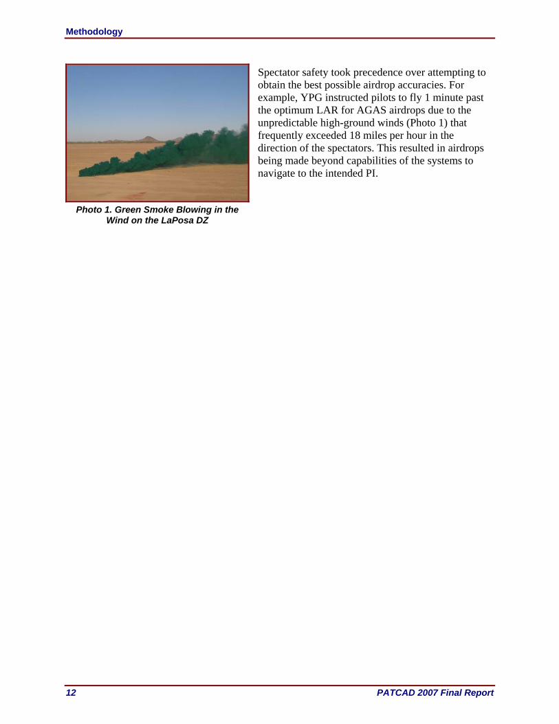
Spectator safety took precedence over attempting to obtain the best possible airdrop accuracies. For example, YPG instructed pilots to fly 1 minute past the optimum LAR for AGAS airdrops due to the unpredictable high-ground winds (Photo 1) that frequently exceeded 18 miles per hour in the direction of the spectators. This resulted in airdrops being made beyond capabilities of the systems to navigate to the intended PI.
Photo 1. Green Smoke Blowing in the
Wind on the LaPosa DZ
Demonstration Observations
PATCAD 2007 Final Report 13
Demonstration Observations Scope
Twenty-eight airdrop systems and related technologies were demonstrated during PATCAD 2007. C-130 and C-17 aircraft flew 14 sorties over a three-day period for a total of 111 airdrops, 28 paratrooper jumps, and 18 dropsonde (weather probe) deployments. The TRWs of airdropped payloads ranged from 5 to 25,200 pounds. Airdrops occurred from 5,000 to 17,500 feet above MSL. More than a quarter of a million pounds of systems and payloads were airdropped during demonstrations. Airdrop offset distances reached as far as 7 km to comply with the safety fan requirements set by YPG. Observations from PATCAD 2007 are summarized in the following sections and are organized by components, airdrop systems, and paratroop systems. A description of each system is included in this section; company profile and contact information are included in Appendix C. Accuracy data and system load profiles for the airdropped systems are also included with each system’s PI normalized for plotting on a common scale. Note: Accuracy measurements were not the primary purpose of the event, and no detailed analysis of the outcomes is provided.
Airdrop-Related Components
GN&C for JPADS, Draper Laboratory
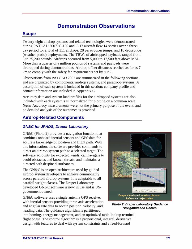
GN&C (Photo 2) provides a navigation function that combines onboard inertial sensors and GPS data for accurate knowledge of location and flight path. With this information, the software provides commands to direct an airdrop system path to a selected target. The software accounts for expected winds, can navigate to avoid obstacles and known threats, and maintains a directed path despite disturbances. The GN&C is an open architecture used by guided airdrop system developers to achieve commonality across parafoil airdrop systems. It is adaptable to all parafoil weight classes. The Draper Laboratory- developed GN&C software is now in use and is US-government owned. GN&C software uses a single antenna GPS receiver with inertial sensors providing three-axis acceleration and angular rate data to obtain position, velocity, and heading data. The guidance algorithm is partitioned into homing, energy management, and an optimized table-lookup terminal flight phase. The control algorithm is a proportional, integral, derivative design with features to deal with system constraints and a feed-forward
Photo 2. Draper Laboratory Guidance
Navigation and Control
Demonstration Observations
14 PATCAD 2007 Final Report
capability to improve response time. GN&C, with the original avionics, enabled the 10,000-pound class parafoil to achieve an expected delivery accuracy of about 150 meters.1 Draper GN&C was flown on the MicroFly and MegaFly systems.
Lightweight Composite ECDS Platform, TSI
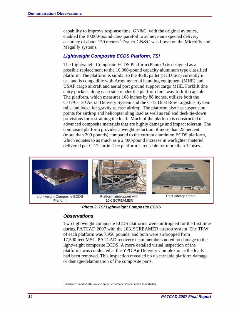
The Lightweight Composite ECDS Platform (Photo 3) is designed as a possible replacement to the 10,000-pound capacity aluminum type classified platform. The platform is similar to the 463L pallet (HCU-6/E) currently in use and is compatible with Army material handling equipment (MHE) and USAF cargo aircraft and aerial port ground support cargo MHE. Forklift tine entry pockets along each side render the platform four-way forklift capable. The platform, which measures 108 inches by 88 inches, utilizes both the C-17/C-130 Aerial Delivery System and the C-17 Dual Row Logistics System rails and locks for gravity release airdrop. The platform also has suspension points for airdrop and helicopter sling load as well as rail and deck tie-down provisions for restraining the load. Much of the platform is constructed of advanced composite materials that are highly damage and impact tolerant. The composite platform provides a weight reduction of more than 25 percent (more than 200 pounds) compared to the current aluminum ECDS platform, which equates to as much as a 2,400-pound increase in warfighter materiel delivered per C-17 sortie. The platform is reusable for more than 12 uses.
Lightweight Composite ECDS
Platform Platform airdropped with
10K SCREAMER Post-airdrop Photo
Photo 3. TSI Lightweight Composite ECDS
Observations Two lightweight composite ECDS platforms were airdropped for the first time during PATCAD 2007 with the 10K SCREAMER airdrop system. The TRW of each platform was 7,950 pounds, and both were airdropped from 17,500 feet MSL. PATCAD recovery team members noted no damage to the lightweight composite ECDS. A more detailed visual inspection of the platforms was conducted at the YPG Air Delivery Complex once the loads had been removed. This inspection revealed no discernable platform damage or damage/delamination of the composite parts.
1 Abstract found at http://www.draper.com/papers/papers2007.html#hattis

Demonstration Observations
PATCAD 2007 Final Report 15
JPADS-MP, PSI
The JPADS-MP (Photo 4) is a roll-on/roll-off mission planner originally developed for the USAF under the management of the US Army NSRDEC. JPADS-MP research and development includes the integration of state-of-the art technologies to improve the accuracy of high-altitude ballistic and guided system airdrop operations. The primary technologies include the Local Analysis and Prediction System developed and maintained by the National Oceanic and Atmospheric Administration Earth System Research Laboratory, the Precision Airdrop Planning System (PAPS) developed and maintained by the Charles Stark Draper Laboratory, and the WindPADS developed and maintained by PSI.
Measured in-situ wind data are received in real time from hand-launched dropsondes through a JPADS-MP four-channel ultra-high frequency (UHF) receiver and assimilated onboard the airdrop aircraft. PAPS accurately simulates the payload roll-out, forward throw/canopy opening, and descent trajectory of the airdrop system through the forecast wind and density field to ground impact in order to produce an accurate CARP. The integrated software package is executed on a portable laptop computer through an operational graphical user interface. Recent advancements in JPADS-MP software include the addition of the Microfly, Firefly and LCADS ballistic high velocity parachute models, the migration of the software to a single operating system, and a newly designed graphical user interface, which was developed with user inputs and guidance and has vastly improved the software training times as well as the time to create a mission. The JPADS-MP software is in the process of being incorporated into the Joint Mission Planning System under contract with the Tybrin Corp. Current work on the integration includes a pipeline to connect the JPADS software with the Portable Flight Planning Software. A full Joint Mission Planning System integration is expected by fiscal year 2010. In addition to software improvements, recent JPADS-MP research, development, and engineering enhancements include an improved GPS on-aircraft retransmission system. PSI’s electronically shifted, multiple-antenna,
JPADS-MP Components
JPADS-MP Installation on a C-17 Aircraft
Photo 4. JPADS-MP Components and Installation

Demonstration Observations
16 PATCAD 2007 Final Report
GPS retransmission system enables reliable GPS ephemeris data updates for onboard guided system AGUs. Also, the JPADS-MP hardware that is installed on the aircraft has been redesigned to the ½ air transport rack configuration, which makes the system rack-mountable in standard avionics racks. JPADS-MP ground and onboard wireless communications between the JPADS-MP laptop and the AGUs are achieved through an 802.11 wireless link. Updated wind data and PI data for each guided system can be uploaded to each AGU while the aircraft is inbound to the DZ. PSI continues to produce and deliver JPADS-MP Block II fly-away kits, GPS dropsondes, and improved GPS retransmission kits to support US high-altitude precision airdrop ballistic and guided system airdrop operations. PSI has established full lifecycle support for deployed systems, including Help Desk and training. Software will continue to be optimized to meet operational user requirements to improve accuracy, reduce processing time, and integrate a ground mission planning tool developed by Earth System Research Laboratory for the optimum deployment of wind dropsondes. The software has been expanded to include support for the high-altitude precision insertion of personnel rigged with ram-air parafoils, including terrain clearance. A JPADS-MP self-contained kit is being developed and will be produced to support personnel insertion operations. The kit will be capable of operating on any aircraft used for personnel airdrop operations independent of power, UHF antenna, and GPS antenna interfaces. The capabilities of the hand-launched GPS dropsonde will be expanded to include programmable data storage/burst transmission modes and radio frequency transmission termination after ground impact for covert operations.
Observations PATCAD team members successfully installed the JPADS-MP onto two C-130 and one C-17 aircraft. USAF operators successfully used the JPADS-MP to plan missions and update wind profiles for greater airdrop accuracies while en route to update the initial mission based on MET data received from the dropsondes they deployed.
SHS, Creare Incorporated
The SHS (Photo 5) uses acoustic soundings to determine accurate estimates of the height and descent velocity of airdrop systems, enabling precise control of final descent maneuvers to increase delivery accuracy and reduce impact velocity. The sensor has an above ground level (AGL) height accuracy within 2 feet of its current position as compared to approximately 60 feet for GPS systems. The sensor has an effective range of up to 500 feet AGL, and it penetrates vegetation, dust, fog, and smoke. The sensor weighs less than 4 pounds and has a rechargeable battery. The SHS includes temperature and barometric pressure sensors. The sensor is packaged in a rugged enclosure (Photo 5) that may be strapped to any payload. The
Photo 5. SHS

Demonstration Observations
PATCAD 2007 Final Report 17
SHS transmits height information to airdrop system AGUs via a standard wireless 802.11 communications link data transmission.
Observations An SHS used with the Draper GN&C software was used to trigger a MicroFly flare. The system was airdropped from 9,999 feet MSL.
WGRS, Wamore Incorporated
The WGRS (Photo 6) is an on-aircraft gate release for 2,200-pound CDS bundles. It is comprised of two main components: the Wireless Gate Release Mechanisms (WGRM) and the Master Control Station (MCS). The WGRS provides a precision timed release of loads and will soon be fully integrated with the JPADS-MP. Currently, guided airdrop systems require a few seconds of separation to deconflict them during canopy deployment. Due to the space needed for a loadmaster to walk alongside the payloads performing manual gate cut, a C-130 is limited to only eight JPADS bundles, half of its full capacity. Using the WGRS, however, a C-130 would be capable of carrying a full complement of 16 JPADS. This allows for fewer aircraft sorties to be flown, reduced fuel and liquid oxygen costs, and fewer aircrews in harm’s way.
WGRS MCS and
WGRM
WGRMs on C-17
Photo 6. WGRS
The WGRS can work in two modes: manual and automatic. In manual mode, the loadmaster has complete control over which loads are released by pressing the appropriate buttons on the MCS, which then wirelessly sends the release signal to the corresponding WGRM. In the automatic mode, which is soon to be integrated into the MP, the MCS is used as a relay and safety station between the WGRMs and the JPADS-MP. The MP can be used to preprogram precision timed release delays. At “green light,” the aircraft navigator will hit a “release” button on the JPADS-MP, initiating a preprogrammed series of commands to be relayed through the MCS to the WGRMs. The loadmaster can see which loads are planned to be released in the upcoming pass via the MCS and can stop the release(s) at any time with a stop button if deemed necessary for safety or other reasons.

Demonstration Observations
18 PATCAD 2007 Final Report
While WGRS can provide added capabilities for JPADS guided systems, it may also enhance accuracy of unguided ICDS payloads. If the scenario allows, the aircraft would make its run-in to the DZ into the wind, releasing the ICDS loads from heaviest to lightest. Users could use accurate knowledge of the winds to determine an optimal release delay between heavy and light payloads. Because light payloads stay aloft longer and hence drift farther, the timing could allow the light payloads to drift back to the DZ. This could dramatically decrease the spread between unguided loads and, therefore, increase overall accuracy of the drop. The WGRS would allow for such precise releases. The WGRS has been tested on over 50 drops from C-17 and C-130 aircraft. It has dropped many different JPADS systems and been used on sticks of up to seven systems as well as up to 10 payloads on a single lift. It has the capability to release up to 40 bundles on a single flight, the full complement of CDS on a C-17.
Observations The WGRS was used twice during PATCAD 2007. During its first use, four Sherpa 1200/2200 systems having a TRW between 700 and 2,000 pounds were restrained in the cargo bay of a USAF C-130. However, before the Sherpa 1200/2200 airdrops could be executed, YPG test control directed the aircraft to return to base due to issues related to systems other than the WGRS or Sherpa 1200/2200 systems. The next use of the WGRS was on a C-17 that airdropped eight 2K SCREAMERs from an altitude of 17,500 feet MSL. The payloads had TRWs of between 1,370 and 2,270 pounds. The loadmaster used the WGRS manual release mode to effect the release of the systems. The airdrop used a 3-second delay between releases to allow for appropriate payload deconfliction. All WGRS mechanisms responded immediately upon the commanded release, and all releases were successful.
Airdrop Systems
AGAS, Capewell Components Company LLC
The AGAS (Photo 7) was designed under a variety of NSRDEC contracts with a primary requirement to make AGAS compatible with the CDS payloads without requiring modifications to the parachute or payload system.
AGAS Rigged
AGAS in Flight (Photo Credit S. Tavan)
AGAS on DZ Post Airdrop
Photo 7. AGAS
Demonstration Observations
PATCAD 2007 Final Report 19
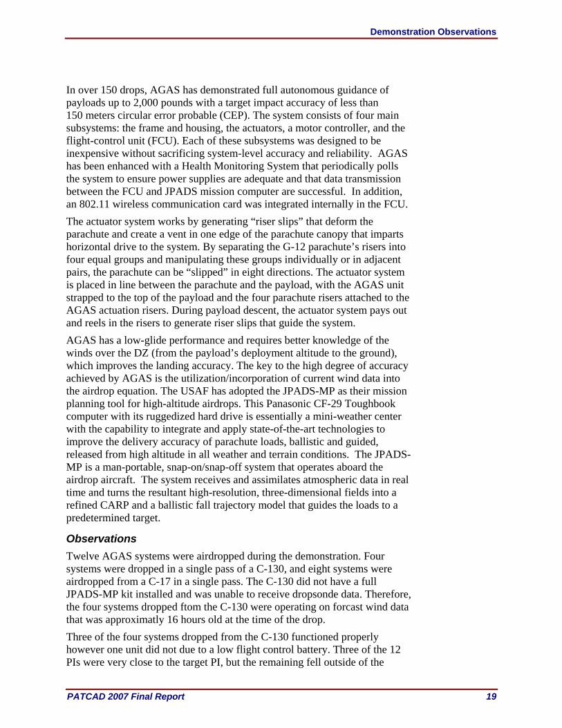
In over 150 drops, AGAS has demonstrated full autonomous guidance of payloads up to 2,000 pounds with a target impact accuracy of less than 150 meters circular error probable (CEP). The system consists of four main subsystems: the frame and housing, the actuators, a motor controller, and the flight-control unit (FCU). Each of these subsystems was designed to be inexpensive without sacrificing system-level accuracy and reliability. AGAS has been enhanced with a Health Monitoring System that periodically polls the system to ensure power supplies are adequate and that data transmission between the FCU and JPADS mission computer are successful. In addition, an 802.11 wireless communication card was integrated internally in the FCU. The actuator system works by generating “riser slips” that deform the parachute and create a vent in one edge of the parachute canopy that imparts horizontal drive to the system. By separating the G-12 parachute’s risers into four equal groups and manipulating these groups individually or in adjacent pairs, the parachute can be “slipped” in eight directions. The actuator system is placed in line between the parachute and the payload, with the AGAS unit strapped to the top of the payload and the four parachute risers attached to the AGAS actuation risers. During payload descent, the actuator system pays out and reels in the risers to generate riser slips that guide the system. AGAS has a low-glide performance and requires better knowledge of the winds over the DZ (from the payload’s deployment altitude to the ground), which improves the landing accuracy. The key to the high degree of accuracy achieved by AGAS is the utilization/incorporation of current wind data into the airdrop equation. The USAF has adopted the JPADS-MP as their mission planning tool for high-altitude airdrops. This Panasonic CF-29 Toughbook computer with its ruggedized hard drive is essentially a mini-weather center with the capability to integrate and apply state-of-the-art technologies to improve the delivery accuracy of parachute loads, ballistic and guided, released from high altitude in all weather and terrain conditions. The JPADS-MP is a man-portable, snap-on/snap-off system that operates aboard the airdrop aircraft. The system receives and assimilates atmospheric data in real time and turns the resultant high-resolution, three-dimensional fields into a refined CARP and a ballistic fall trajectory model that guides the loads to a predetermined target.
Observations Twelve AGAS systems were airdropped during the demonstration. Four systems were dropped in a single pass of a C-130, and eight systems were airdropped from a C-17 in a single pass. The C-130 did not have a full JPADS-MP kit installed and was unable to receive dropsonde data. Therefore, the four systems dropped ftom the C-130 were operating on forcast wind data that was approximatly 16 hours old at the time of the drop. Three of the four systems dropped from the C-130 functioned properly however one unit did not due to a low flight control battery. Three of the 12 PIs were very close to the target PI, but the remaining fell outside of the

Demonstration Observations
20 PATCAD 2007 Final Report
500-meter accuracy circle (Figure 3). These “misses” were in part the results of YPG range control safety constraints. YPG directed the C-17 aircrew to fly 1-minute (or approximately 2 miles) farther away from the viewing stands and past the JPADS-MP calculated CARP. Flight profile and load characteristics for these events are shown in Table 5. Select flight path plots are shown in Appendix D.
Table 5. AGAS Airdrop Profile and Results
Offset (km)
Altitude (MSL)
TRW (pounds)
Winds (m/s – from in
degrees)
Miss Distance (meters)
Comments
5.1 17,500 2,022 5.8 – 360 1,653 5.0 17,500 2,221 5.8 – 360 615 5.1 17,500 2,121 5.8 – 360 1,303 5.0 17,500 2,318 5.8 – 360 804 0.4 17,500 1,822 0.9 – 180 181 0.9 17,500 1,413 0.9 – 180 2,272 0.3 17,500 1,922 0.9 – 180 207 0.7 17,500 1,723 0.9 – 180 133 0.8 17,500 1,514 0.9 – 180 718 1.2 17,500 1,218 0.9 – 180 2,274 1.2 17,500 1,304 0.9 – 180 586 1.1 17,500 1,624 0.9 – 180 579
YPG test controllers directed the aircrew to fly 1 minute past the LAR before releasing the AGAS from the aircraft.
m/s = meters per second
CADS, Cobham PLC
The CADS (Photo 8) is a radio frequency-controlled system that uses either a ground-based or airborne transmitter. The CADS uses a ram air parachute connected to an AGU that receives coded radio commands and converts them into steering actions. The payload is suspended below the AGU. Radio commands can be one of three control modes: manual control from a ground transmitter, automatic control from a ground transmitter, or in-flight control from a parachutist via touch gloves. Operators can switch between modes at any time, and up to four CADS can be controlled from each ground transmitter. Once acquired visually, the transmitter is switched to manual for a controlled, flared landing.
m = meter
Figure 3. AGAS PI Plot
Demonstration Observations
PATCAD 2007 Final Report 21
CADS Rigged
CADS in Flight
(Photo Credit S. Tavan)
CADS on DZ Post Airdrop
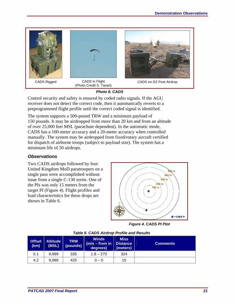
Photo 8. CADS
Control security and safety is ensured by coded radio signals. If the AGU receiver does not detect the correct code, then it automatically reverts to a preprogrammed flight profile until the correct coded signal is identified. The system supports a 500-pound TRW and a minimum payload of 150 pounds. It may be airdropped from more than 20 km and from an altitude of over 25,000 feet MSL (parachute dependent). In the automatic mode, CADS has a 100-meter accuracy and a 20-meter accuracy when controlled manually. The system may be airdropped from fixed/rotary aircraft certified for dispatch of airborne troops (subject to payload size). The system has a minimum life of 50 airdrops.
Observations Two CADS airdrops followed by four United Kingdom MoD paratroopers on a single pass were accomplished without issue from a single C-130 sortie. One of the PIs was only 15 meters from the target PI (Figure 4). Flight profiles and load characteristics for these drops are shown in Table 6.
Table 6. CADS Airdrop Profile and Results
Offset (km)
Altitude (MSL)
TRW (pounds)
Winds (m/s – from in
degrees)
Miss Distance (meters)
Comments
5.1 9,999 335 1.8 – 270 324 4.2 9,999 425 0 – 0 15
Figure 4. CADS PI Plot

Demonstration Observations
22 PATCAD 2007 Final Report
Dragon Train, Aerobotics, LLC
Dragon Train uses a proprietary algorithm and a GN&C module for high-altitude parachute airdrops/jumps for navigation in a family of low-cost, semi-disposable distributed cargo parachutes called Dragon Train. A modular Dragon Train I system (Photo 9), without the canopy, weighs under 10 pounds. The system consists of a GN&C module, dual actuators, and a wiring harness and battery. Dragon Train I can fly various personnel-sized canopies, hemispheric, parabolic, airfoil, or wings with payloads up to 700 pounds (100-pound minimum) utilizing a T-10, MC-1, or MC-5 canopy. The only high-value component in the Dragon Train is the 2-pound GN&C. Dragon Train II will have a 2,000-pound payload capacity (1,000-pound minimum) and utilize a G-12 canopy. Dragon Train III will have a 5,000-pound payload capacity, 2,500-pound minimum and utilize a G-11 canopy.
Dragon Train Rigged
Dragon Train in Flight
(Photo Credit S. Tavan)
Dragon Train on DZ Post Airdrop
Photo 9. Dragon Train
The GN&C module incorporates a custom inertial navigation unit populated with the following sensors: three-axis magnetometer, three-axis accelerometer, integrated GPS, barometric altitude and airspeed sensors, and actuator feedback sensors. The system also has an integrated, barometric GPS-based filter for improved altitude estimation. The GN&C can be software modified for various canopy glide rations. Aerobotics has developed a proprietary 1.68-pound dropsonde that is used during testing and operation. The dropsonde falls at 3,500 feet/minute allowing for accurate wind estimates. The proprietary GN&C algorithms can accept both forecasted wind data and real-time dropsonde data. Dragon Train’s normal operation altitude is 6,000 to 13,500 feet AGL with the higher the altitude, the larger the LAR. Operational altitudes may be increased to 35,000 feet AGL with a modest increase in battery capacity. Flying the MC-5 and MC1-D canopies, the Dragon Train has consistently landed within 100 meters of its intended PI.

Demonstration Observations
PATCAD 2007 Final Report 23
Observations Three Dragon Train airdrops were performed during PATCAD 2007 spread across two C-130 sorties. All systems were dropped using forecast winds due to deployment problems with the dropsondes in the C-130. All Dragon Train systems deployed from the aircraft without obvious difficultly. All three systems navigated towards the DZ but had large landing deviations. Figure 5 and Table 7 show the profiles and results for these drops. The first drop used an MC1-D canopy and required more accurate winds to project a better trajectory to the PI. Upon deployment, this system initiated autonomous control and successfully navigated itself towards the DZ. The low-glide ratio of the MC1-D made this canopy highly susceptible to errors in the wind profile. Errors in the wind projections caused this system to have a significant landing deviation from the DZ. The second system flew an MC-5. Upon deployment, an electro-mechanical malfunction initiated an extremely tight right turn. Manual control was initiated from the ground station, and stable control was regained at approximately 5,000 feet AGL. The Dragon Train was then placed into an autonomous mode. While it continued to fly towards the PI, it lost sufficient altitude in the high winds that it was unable to reach the PI. The third system, utilizing an MC-5 canopy, initiated autonomous control upon deployment and began navigating its trajectory toward the PI. However, when Dragon Train shifted to the approach mode at 600 feet, no right turn was initiated into the PI, and it commenced to drift down wind. At this time, it was discovered that the right steering line had broken and was trailing behind. The cause for the line break was unknown, but evidence shows that it occurred upon deployment. Even without right steering control, the system was capable of landing 753 meters from the PI. All three PIs were beyond the 500-meter accuracy circle shown in Figure 5. Table 7 shows the flight profiles and load characteristics for these drops.
Table 7. Dragon Train Airdrop Profile and Results
Offset (km)
Altitude (MSL)
TRW (pounds)
Winds (m/s – from in
degrees)
Miss Distance (meters)
Comments
4.9 9,999 378 4.5 – 052 1,317
5.3 9,999 378 4.5 – 052 1,320 Deployment break release malfunction
1.6 9,999 379 0.9 – 160 753 Broken right control line
Figure 5. Dragon Train PI Plot

Demonstration Observations
24 PATCAD 2007 Final Report
FireFly, Airborne Systems The 2K FireFly (Photo 10), selected by the US Army for their 2K JPADS formal program of record, is a fully autonomous GPS-guided CDS capable of carrying payloads from 500 to 2,200 pounds. The canopy is a fully elliptical ram air parachute with a glide ratio of 3.75:1 for maximum offset capability. The FireFly will be fully qualified for maximum payloads up to 25,000 feet MSL and has repeatedly demonstrated the capability to land within 150 meters of the designated PI.
FireFly Rigged
FireFly in Flight
(Photo Credit S. Tavan) FireFly on DZ Post Airdrop
Photo 10. FireFly
The 2K FireFly is one of four JPADS platforms developed and manufactured by Airborne Systems, which also produces the MicroFly, DragonFly, and MegaFly. All operate with a common algorithm, user interface, and MP. The packing methodology for all systems is similar as are the AGU interfaces, so little additional training is required to qualify riggers on different systems. The 75-pound FireFly AGU does not require any tools for the installation and removal of canopy and spool covers. The FireFly 1025 ram air canopy weighs 67 pounds and spans 58 feet. The 2K FireFly is compatible with the JPADS-MP and the Airborne Systems MP. In addition to the JPADS-MP, the Airborne Systems MP is capable of running simulated missions in virtual operational environments when using terrain-mapping software. All systems are compatible with an optional remote control unit. The remote control unit allows a user to continuously monitor the system onboard the aircraft and in flight to determine location and heading. If desired, an operator may override the AGU and fly the system manually. Currently, the remote control unit does not operate on a secure frequency; however, future development efforts for a secure remote control unit are being investigated so that an operator in the field may take advantage of the benefits that this additional tool can provide. Users can directly program the FireFly AGU through the AGU’s user interface panel rather than relying on the use of a laptop computer or the
Demonstration Observations
PATCAD 2007 Final Report 25
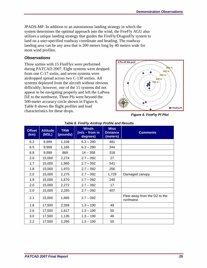
JPADS-MP. In addition to an autonomous landing strategy in which the system determines the optimal approach into the wind, the FireFly AGU also utilizes a unique landing strategy that guides the FireFly/DragonFly system to land on a user-specified roadway coordinate and heading. The roadway landing area can be any area that is 200 meters long by 40 meters wide for most wind profiles.
Observations Three sorties with 15 FireFlys were performed during PATCAD 2007. Eight systems were dropped from one C-17 sortie, and seven systems were airdropped spread across two C-130 sorties. All systems deployed from the aircraft without obvious difficultly; however, one of the 15 systems did not appear to be navigating properly and left the LaPosa DZ to the northwest. Three PIs were beyond the 500-meter accuracy circle shown in Figure 6. Table 8 shows the flight profiles and load characteristics for these drops.
Table 8. FireFly Airdrop Profile and Results
Offset (km)
Altitude (MSL)
TRW (pounds)
Winds (m/s – from in
degrees)
Miss Distance (meters)
Comments
6.2 9,999 1,108 6.3 – 280 481 6.5 9,999 1,165 6.3 – 280 344 6.8 9,999 869 14 – 358 318 2.0 15,000 2,274 2.7 – 092 27 1.7 15,000 1,960 2.7 – 092 541 1.8 15,000 1,970 2.7 – 092 256 2.0 15,000 2,275 2.7 – 092 1,729 Damaged canopy 1.9 15,000 1,670 2.7 – 092 240 2.0 15,000 2,272 2.7 – 092 17 2.0 15,000 2,265 2.7 – 092 407
2.1 15,000 1,665 2.7 – 092 Flew away from the DZ to the northwest
1.8 17,500 2,269 1.3 – 190 49 2.6 17,500 1,617 1.3 – 190 50 3.0 17,500 1,135 1.3 – 190 46 2.2 17,500 2,266 1.3 – 190 55
Figure 6. FireFly PI Plot
Demonstration Observations
26 PATCAD 2007 Final Report
Improved Container Delivery System (ICDS) , NSRDEC and USAF
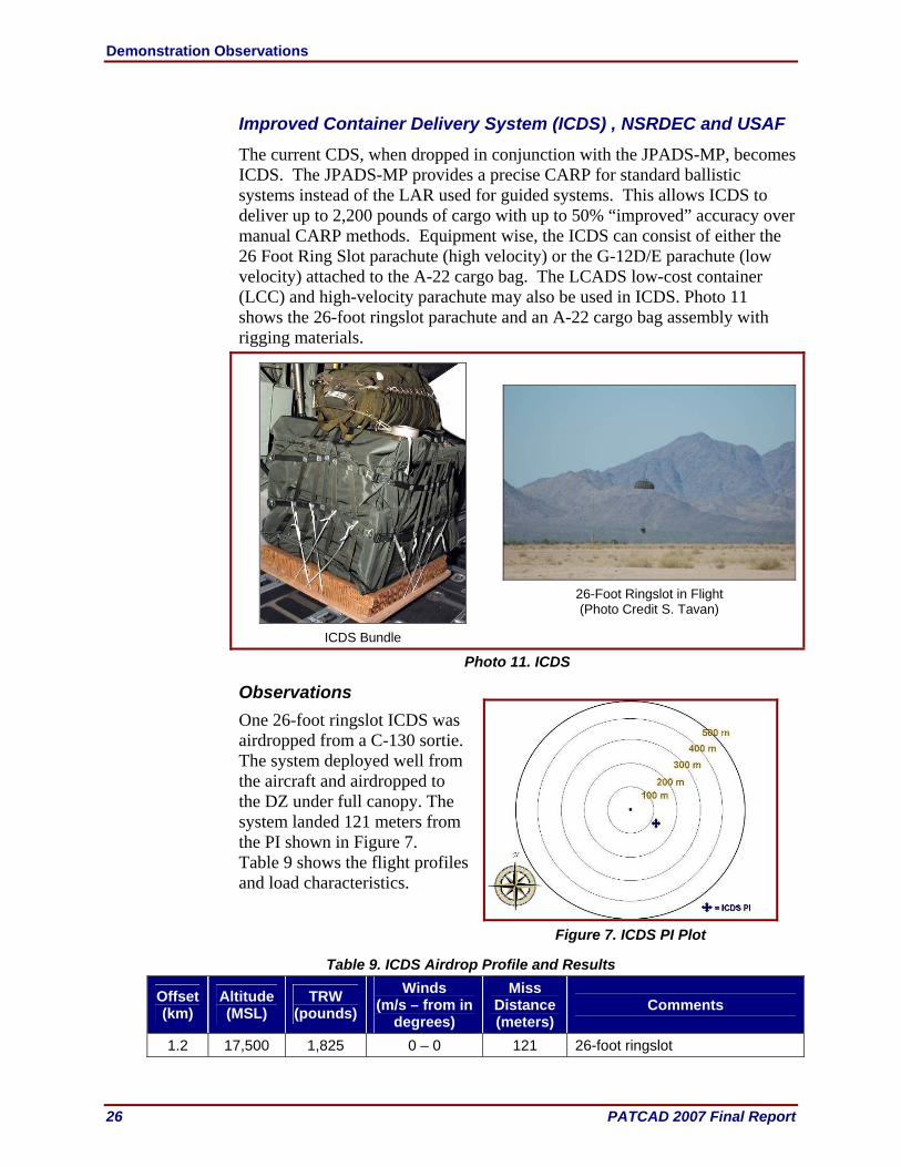
The current CDS, when dropped in conjunction with the JPADS-MP, becomes ICDS. The JPADS-MP provides a precise CARP for standard ballistic systems instead of the LAR used for guided systems. This allows ICDS to deliver up to 2,200 pounds of cargo with up to 50% “improved” accuracy over manual CARP methods. Equipment wise, the ICDS can consist of either the 26 Foot Ring Slot parachute (high velocity) or the G-12D/E parachute (low velocity) attached to the A-22 cargo bag. The LCADS low-cost container (LCC) and high-velocity parachute may also be used in ICDS. Photo 11 shows the 26-foot ringslot parachute and an A-22 cargo bag assembly with rigging materials.
ICDS Bundle
26-Foot Ringslot in Flight (Photo Credit S. Tavan)
Photo 11. ICDS
Observations One 26-foot ringslot ICDS was airdropped from a C-130 sortie. The system deployed well from the aircraft and airdropped to the DZ under full canopy. The system landed 121 meters from the PI shown in Figure 7. Table 9 shows the flight profiles and load characteristics.
Table 9. ICDS Airdrop Profile and Results
Offset (km)
Altitude (MSL)
TRW (pounds)
Winds (m/s – from in
degrees)
Miss Distance (meters)
Comments
1.2 17,500 1,825 0 – 0 121 26-foot ringslot
Figure 7. ICDS PI Plot

Demonstration Observations
PATCAD 2007 Final Report 27
High-Velocity LCADS, PM FSS
The LCADS (Photo 12) is a modular suite of low-cost, one-time use air items designed for use when recovery of the air items is unlikely (humanitarian) or impractical (combat). It is comprised of parachutes, containers, and platforms configured for either low-velocity ground impact of 28.5 feet per second or a high-velocity ground impact of 90 feet per second. LCADS components have an average 55- to 80-percent reduction in cost when compared to their reusable counterparts. Additionally, use of readily available materials and ease of manufacturing is emphasized in order to minimize production lead times and broaden the industrial base for LCADS items.
LCADS LCCs
High-velocity in Flight (Photo Credit S. Tavan)
Photo 12. LCADS
The LCADS LCC is an inexpensive alternative to the heavier, more durable A-22 cargo container. It weighs about 10 pounds and is made of a lightweight polypropylene and six pieces of hardware. The container can hold up to 2,200 pounds of supplies and is suitable for both high- and low-velocity airdrops from C-17 or C-130 aircraft. The LCADS high-velocity parachute is capable of delivering up to 2,200 pounds of cargo and has performance characteristics similar to the 26-foot ringslot parachute. It can be used with either the LCADS LCC or the standard A-22 container for delivery of non-fragile supplies. The LCADS low-velocity parachute is capable of delivering up to 2,200 pounds of cargo and has performance characteristics similar to the 64-foot G-12 recovery parachute. It can also be used with either the LCADS LCC or the standard A-22 container; however, it is usually used for airdrops of semi-fragile items that require a low-velocity ground impact. The JPADS-MP may be used to calculate an air release point for LCADS parachutes to increase airdrop accuracy. LCADS parachutes have a tactical advantage by using a breakaway static line at all altitudes.

Demonstration Observations
28 PATCAD 2007 Final Report
Observations Two high-velocity systems having a total rigged weight of 1,838 and 1,638 pounds were airdropped from a C-130 from an altitude of 9,999 feet MSL. LCADS accuracy and wind data were not available. The systems were revovered before data could be collected on the systems. The LCADS systems deployed well from the aircraft and airdropped to the DZ under full canopies. No LCADS low-velocity parachutes were airdropped because they are still in pre-production status.
MegaFly, Airborne Systems
The MegaFly (Photo 13) is a fully autonomous, GPS-guided delivery system capable of carrying payloads from 20,000 to 30,000 pounds. The canopy is a fully elliptical ram air parachute with a glide ratio of 3.75:1 for maximum offset capability. The FireFly is fully qualified for maximum payloads up to 25,000 feet MSL.
MegaFly Rigged
MegaFly in Flight
(Photo Credit S. Tavan)
MegaFly on DZ Post Airdrop
Photo 13. MegaFly The MegaFly is one of four JPADS platforms developed and manufactured by Airborne Systems, which also produces the MicroFly, FireFly, and DragonFly. All operate with a common algorithm, user interface, and MP. The packing methodology for all systems is identical as are the AGU interfaces, so little additional training is required to qualify riggers on different systems. The MegaFly has a 9,000-square foot, 170-feet long, 900-pound modular canopy that is made of five separate segments for ease of recovery. The recovery procedure for the MegaFly consists of separating the canopy segments, slider segments, and AGU interface frame segments from one another. Each component weighs less than 250 pounds. The weight of the AGU is 375 pounds and is suspended between the parachute and payload. The design is based on the common systems architecture of Airborne Systems’ family of JPADS systems. MegaFly is extracted from an aircraft using standard airdrop equipment and is deployed as a conventional ram air canopy without pyrotechnic cutters or timers. MegaFly is also compatible with the current JPADS-MP. All systems
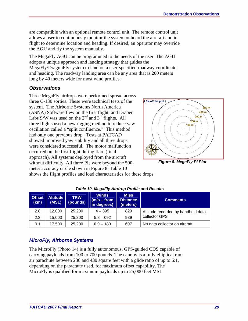
Demonstration Observations
PATCAD 2007 Final Report 29
are compatible with an optional remote control unit. The remote control unit allows a user to continuously monitor the system onboard the aircraft and in flight to determine location and heading. If desired, an operator may override the AGU and fly the system manually. The MegaFly AGU can be programmed to the needs of the user. The AGU adopts a unique approach and landing strategy that guides the MegaFly/DragonFly system to land on a user-specified roadway coordinate and heading. The roadway landing area can be any area that is 200 meters long by 40 meters wide for most wind profiles.
Observations Three MegaFly airdrops were performed spread across three C-130 sorties. These were technical tests of the system. The Airborne Systems North America (ASNA) Software flew on the first flight, and Draper Labs S/W was used on the 2nd and 3rd flights. All three flights used a new rigging method to reduce yaw oscillation called a “split confluence.” This method had only one previous drop. Tests at PATCAD showed improved yaw stability and all three drops were considered successful. The motor malfunction occurred on the first flight during flare (final approach). All systems deployed from the aircraft without difficulty. All three PIs were beyond the 500-meter accuracy circle shown in Figure 8. Table 10 shows the flight profiles and load characteristics for these drops.
Table 10. MegaFly Airdrop Profile and Results
Offset (km)
Altitude (MSL)
TRW (pounds)
Winds (m/s – from in degrees)
Miss Distance (meters)
Comments
2.8 12,000 25,200 4 – 395 829 2.3 15,000 25,200 5.8 – 092 939
Altitude recorded by handheld data collector GPS
9.1 17,500 25,200 0.9 – 180 697 No data collector on aircraft
MicroFly, Airborne Systems
The MicroFly (Photo 14) is a fully autonomous, GPS-guided CDS capable of carrying payloads from 100 to 700 pounds. The canopy is a fully elliptical ram air parachute between 230 and 430 square feet with a glide ratio of up to 6:1, depending on the parachute used, for maximum offset capability. The MicroFly is qualified for maximum payloads up to 25,000 feet MSL.
Figure 8. MegaFly PI Plot

Demonstration Observations
30 PATCAD 2007 Final Report
MicroFly Rigged
MicroFly on DZ Post Airdrop
Photo 14. MicroFly
The MicroFly emphasizes ease of use, flexibility, and low cost by incorporating proven technology. The MicroFly is intended to fly autonomously to a PI without external guidance. Should a user desire to fly the MicroFly manually, a remote is included that can control up to 10 MicroFly systems. The MicroFly can be used to accompany high-altitude, low-opening/HAHO teams during insertion and can be used to resupply elements on the ground. The MicroFly will match the speed and rate of descent of a jumper under canopy. This allows the MicroFly to lead the unit to the PI while allowing the unit to remain in close contact with the MicroFly. Being in close proximity of the MicroFly ensures that the unit will not become separated from its equipment and allows the MicroFly to be used as a pathfinder to the PI. The MicroFly can be used with any canopy manufactured by Airborne Systems, including the MT-1X, MC-4, MC-5, MT-1Z, HG-380, and the new Intruder canopy. The MicroFly is one of four JPADS platforms developed and manufactured by Airborne Systems, which also produces the FireFly, DragonFly, and MegaFly. All operate with a common algorithm, user interface, and MP. The packing methodology for all systems is identical as are AGU interfaces, so little additional training is required to qualify riggers on different systems. The MicroFly AGU weighs 30 pounds and has a battery life of five flights from 18,000 feet. The MicroFly AGU is based on the DragonFly and FireFly JPADS designs that are compatible with the JPADS-MP and the Airborne Systems MP.
Observations Six MicroFly airdrops spread across two C-130 sorties were performed during PATCAD 2007. All systems deployed from the aircraft but with difficulties. On the first sortie, three MicroFly systems were inadvertently airdropped at the wrong point in time from the C-130 loading ramp as it was lowered in preparation for the airdrop to the LaPosa DZ. The airdrop distance was great enough so as not to allow the MicroFly systems to reach the DZ. For the second sortie, all of the systems exited the aircraft without difficulty, but one
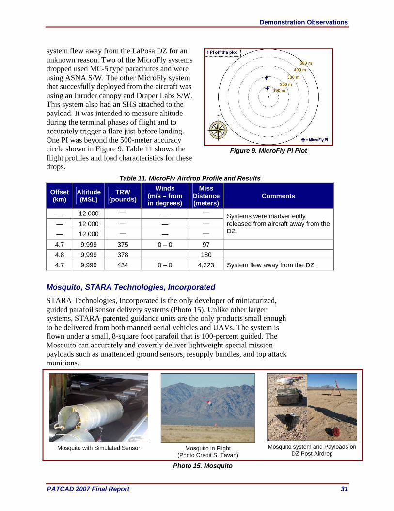
Demonstration Observations
PATCAD 2007 Final Report 31
system flew away from the LaPosa DZ for an unknown reason. Two of the MicroFly systems dropped used MC-5 type parachutes and were using ASNA S/W. The other MicroFly system that succesfully deployed from the aircraft was using an Inruder canopy and Draper Labs S/W. This system also had an SHS attached to the payload. It was intended to measure altitude during the terminal phases of flight and to accurately trigger a flare just before landing. One PI was beyond the 500-meter accuracy circle shown in Figure 9. Table 11 shows the flight profiles and load characteristics for these drops.
Table 11. MicroFly Airdrop Profile and Results
Offset (km)
Altitude (MSL)
TRW (pounds)
Winds (m/s – from in degrees)
Miss Distance (meters)
Comments
— 12,000 — — — — 12,000 — — — — 12,000 — — —
Systems were inadvertently released from aircraft away from the DZ.
4.7 9,999 375 0 – 0 97 4.8 9,999 378 180 4.7 9,999 434 0 – 0 4,223 System flew away from the DZ.
Mosquito, STARA Technologies, Incorporated
STARA Technologies, Incorporated is the only developer of miniaturized, guided parafoil sensor delivery systems (Photo 15). Unlike other larger systems, STARA-patented guidance units are the only products small enough to be delivered from both manned aerial vehicles and UAVs. The system is flown under a small, 8-square foot parafoil that is 100-percent guided. The Mosquito can accurately and covertly deliver lightweight special mission payloads such as unattended ground sensors, resupply bundles, and top attack munitions.
Mosquito with Simulated Sensor
Mosquito in Flight
(Photo Credit S. Tavan)
Mosquito system and Payloads on
DZ Post Airdrop
Photo 15. Mosquito
Figure 9. MicroFly PI Plot

Demonstration Observations
32 PATCAD 2007 Final Report
The Mosquito can accommodate any payload weighing between 1 and 150 pounds. Payloads can be, but are not limited to, sensors that detect the presence of weapons of mass destruction, munitions to neutralize enemy military hardware, or personnel or blood packets to resupply injured troops in remote, inaccessible locations. The Mosquito Generic Delivery System (GDS) can be preprogrammed with target coordinates before a mission and reprogrammed with updated coordinates moments before dropping from the aircraft. The system can also program the parafoil opening altitude or have it open upon exit from an aircraft. The system will also detach a payload from GDS while over the target at a preprogrammed altitude. The GDS can also perform a flared, soft landing maneuver before hitting the ground. The GDS includes a highly accurate Wide-area Augmentation System GPS receiver that receives raw satellite data to calculate position 10 times per second.
Observations Seven Mosquito airdrops spread across two C-130 sorties were executed during PATCAD. Four of the seven systems functioned as intended; the other 3 malfunctioned for various reasons listed in the table below. Accuracy for the Mosquito was measured at the point where the payload impacted the ground since the payload intentionally separates from the system at a given altitude. One Mosquito was not found and, hence, not plotted (Figure 10). Table 12 shows the flight profiles and load characteristics for these drops.
Table 12. Mosquito Airdrop Profile and Results
Offset (km)
Altitude (MSL)
TRW (pounds)
Winds (m/s – from in degrees)
Miss Distance (meters)
Comments
3.7 9,999 150 6.3 – 360 31 3.9 9,999 5 6.3 – 360 3 2.1 9,999 5 0.9 – 180 8 2.1 9,999 5 0.9 – 180 11 — 9,999 20 0.9 – 180 227 System was over gained.
— 9,999 20 0.9 – 180 Unknown System “activated early” in doorway of C130, chute exploded on deployment due to drogue timer timing out early.
— 9,999 20 — — System “activated early” in doorway of C130 and was not deployed.
Figure 10. Mosquito PI Plot
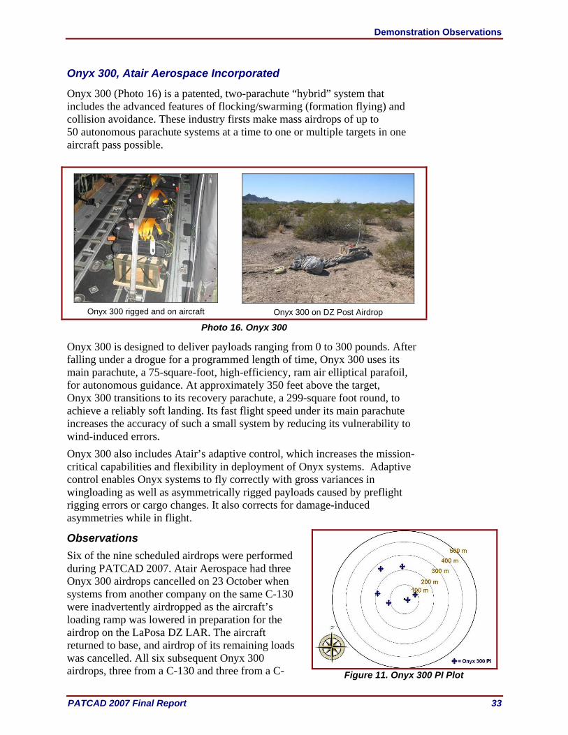
Demonstration Observations
PATCAD 2007 Final Report 33
Onyx 300, Atair Aerospace Incorporated
Onyx 300 (Photo 16) is a patented, two-parachute “hybrid” system that includes the advanced features of flocking/swarming (formation flying) and collision avoidance. These industry firsts make mass airdrops of up to 50 autonomous parachute systems at a time to one or multiple targets in one aircraft pass possible.
Onyx 300 rigged and on aircraft
Onyx 300 on DZ Post Airdrop
Photo 16. Onyx 300
Onyx 300 is designed to deliver payloads ranging from 0 to 300 pounds. After falling under a drogue for a programmed length of time, Onyx 300 uses its main parachute, a 75-square-foot, high-efficiency, ram air elliptical parafoil, for autonomous guidance. At approximately 350 feet above the target, Onyx 300 transitions to its recovery parachute, a 299-square foot round, to achieve a reliably soft landing. Its fast flight speed under its main parachute increases the accuracy of such a small system by reducing its vulnerability to wind-induced errors. Onyx 300 also includes Atair’s adaptive control, which increases the mission-critical capabilities and flexibility in deployment of Onyx systems. Adaptive control enables Onyx systems to fly correctly with gross variances in wingloading as well as asymmetrically rigged payloads caused by preflight rigging errors or cargo changes. It also corrects for damage-induced asymmetries while in flight.
Observations Six of the nine scheduled airdrops were performed during PATCAD 2007. Atair Aerospace had three Onyx 300 airdrops cancelled on 23 October when systems from another company on the same C-130 were inadvertently airdropped as the aircraft’s loading ramp was lowered in preparation for the airdrop on the LaPosa DZ LAR. The aircraft returned to base, and airdrop of its remaining loads was cancelled. All six subsequent Onyx 300 airdrops, three from a C-130 and three from a C-
Figure 11. Onyx 300 PI Plot
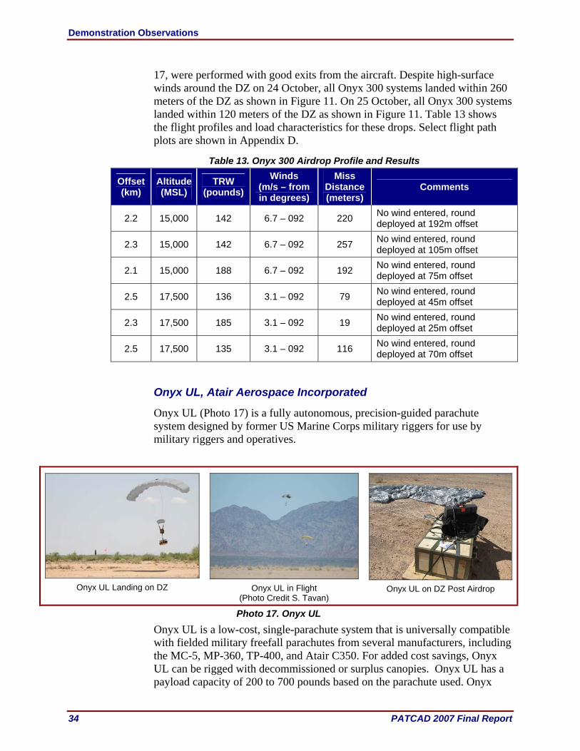
Demonstration Observations
34 PATCAD 2007 Final Report
17, were performed with good exits from the aircraft. Despite high-surface winds around the DZ on 24 October, all Onyx 300 systems landed within 260 meters of the DZ as shown in Figure 11. On 25 October, all Onyx 300 systems landed within 120 meters of the DZ as shown in Figure 11. Table 13 shows the flight profiles and load characteristics for these drops. Select flight path plots are shown in Appendix D.
Table 13. Onyx 300 Airdrop Profile and Results
Offset (km)
Altitude (MSL)
TRW (pounds)
Winds (m/s – from in degrees)
Miss Distance (meters)
Comments
2.2 15,000 142 6.7 – 092 220 No wind entered, round deployed at 192m offset
2.3 15,000 142 6.7 – 092 257 No wind entered, round deployed at 105m offset
2.1 15,000 188 6.7 – 092 192 No wind entered, round deployed at 75m offset
2.5 17,500 136 3.1 – 092 79 No wind entered, round deployed at 45m offset
2.3 17,500 185 3.1 – 092 19 No wind entered, round deployed at 25m offset
2.5 17,500 135 3.1 – 092 116 No wind entered, round deployed at 70m offset
Onyx UL, Atair Aerospace Incorporated
Onyx UL (Photo 17) is a fully autonomous, precision-guided parachute system designed by former US Marine Corps military riggers for use by military riggers and operatives.
Onyx UL Landing on DZ
Onyx UL in Flight
(Photo Credit S. Tavan) Onyx UL on DZ Post Airdrop
Photo 17. Onyx UL
Onyx UL is a low-cost, single-parachute system that is universally compatible with fielded military freefall parachutes from several manufacturers, including the MC-5, MP-360, TP-400, and Atair C350. For added cost savings, Onyx UL can be rigged with decommissioned or surplus canopies. Onyx UL has a payload capacity of 200 to 700 pounds based on the parachute used. Onyx
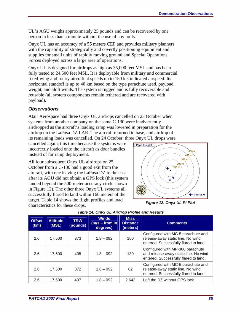
Demonstration Observations
PATCAD 2007 Final Report 35
UL’s AGU weighs approximately 25 pounds and can be recovered by one person in less than a minute without the use of any tools. Onyx UL has an accuracy of a 55 meters CEP and provides military planners with the capability of strategically and covertly positioning equipment and supplies for small units of rapidly moving ground and Special Operations Forces deployed across a large area of operations. Onyx UL is designed for airdrops as high as 35,000 feet MSL and has been fully tested to 24,500 feet MSL. It is deployable from military and commercial fixed-wing and rotary aircraft at speeds up to 150 kts indicated airspeed. Its horizontal standoff is up to 40 km based on the type parachute used, payload weight, and aloft winds. The system is rugged and is fully recoverable and reusable (all system components remain tethered and are recovered with payload).
Observations Atair Aerospace had three Onyx UL airdrops cancelled on 23 October when systems from another company on the same C-130 were inadvertently airdropped as the aircraft’s loading ramp was lowered in preparation for the airdrop on the LaPosa DZ LAR. The aircraft returned to base, and airdrop of its remaining loads was cancelled. On 24 October, three Onyx UL drops were cancelled again, this time because the systems were incorrectly loaded onto the aircraft as door bundles instead of for ramp deployment. All four subsequent Onyx UL airdrops on 25 October from a C-130 had a good exit from the aircraft, with one leaving the LaPosa DZ to the east after its AGU did not obtain a GPS lock (this system landed beyond the 500-meter accuracy circle shown in Figure 12). The other three Onyx UL systems all successfully flared to land within 160 meters of the target. Table 14 shows the flight profiles and load characteristics for these drops.
Table 14. Onyx UL Airdrop Profile and Results
Offset (km)
Altitude (MSL)
TRW (pounds)
Winds (m/s – from in
degrees)
Miss Distance (meters)
Comments
2.6 17,500 373 1.8 – 092 160 Configured with MC-5 parachute and release-away static line. No wind entered. Successfully flared to land.
2.6 17,500 405 1.8 – 092 130 Configured with MP-360 parachute and release-away static line. No wind entered. Successfully flared to land.
2.6 17,500 372 1.8 – 092 62 Configured with MC-5 parachute and release-away static line. No wind entered. Successfully flared to land.
2.6 17,500 497 1.8 – 092 2,642 Left the DZ without GPS lock
Figure 12. Onyx UL PI Plot

Demonstration Observations
36 PATCAD 2007 Final Report
PANTHER 500, Pioneer Aerospace Corporation/Aerazur
The PANTHER Guidance System provides accurate delivery to a selected landing point by GPS navigation with minimal input (waypoint and landing coordinates). The PANTHER can be adapted to any payload (Photo 18). The PANTHER 500 is compatible with the military A7 class of CDS and has a 550-pound payload capacity. The system is mission capable in winds to approximately 80 feet per second weight affected.
PANTHER 500 Rigged
PANTHER 500 in Flight (Photo Credit
S. Tavan)
Photo 18. PANTHER 500 The PANTHER 500 has a 46-pound AGU that has a capability to provide for flared, soft landings. The system configures in flight for steering control and automatically calculates winds; landing is wind-oriented or direction selectable. The landing point and up to three waypoints are programmable through a secure digital card, serial interface cable, or wirelessly through a ground unit interface. An optional ground unit interface is an executable program that loads onto a personal computer or laptop and a telemetry user interface box. With this setup, the system can navigate in an automatic or manual control mode that has a 40-km line-of-sight range. In-flight changes can be made to the intended PI coordinates. The ground unit interface provides real-time flight with vertical, horizontal, and three-dimensional displays. It also provides real-time performance monitoring and data acquisition, pre-mission simulation, and post-mission flight playback. The system flies under a 365-square foot, 12-pound parafoil.
Observations Nine airdrops were performed from a C-130, but one system navigated away from the DZ. This system’s right parafoil cell failed on deployment. The system was still capable of steering but a code error existed in a “Timed Wind Update” maneuver, which resulted in a locked right brake to the ground. The smaller (500) Panther units used a different ‘Wind Update’ method and were not subject to this error. This particular code error was the result of a minor

Demonstration Observations
PATCAD 2007 Final Report 37
change to this maneuver after its last flight in January 07. The code error from this “timed” procedure was fixed post-PATCAD07. One PI was beyond the 500-meter accuracy circle shown in Figure 13. Table 15 shows the flight profiles and load characteristics for these drops. Select flight path plots are shown in Appendix D.
Table 15. Panther 500 Airdrop Profile and Results
Offset (km)
Altitude (MSL)
TRW (pounds)
Winds (m/s – from in
degrees)
Miss Distance (meters)
Comments
4.5 9,999 469 4 – 280 35 4.5 9,999 466 4 – 280 202 4.5 9,999 468 4 – 280 203 1.8 9,999 473 0.4 – 300 346 2.1 9,999 470 0.4 – 300 224 1.6 9,999 461 0.4 – 300 101 1.2 9,999 468 1.8 – 092 191 1.2 9,999 468 1.8 – 092 2,126 Navigated away from DZ 1.2 9,999 458 1.8 – 092 334
PANTHER 2K, Pioneer Aerospace Corporation/Aerazur
The PANTHER Guidance System provides accurate delivery to a selected landing point by GPS navigation with minimal input (enter waypoint and landing coordinates). The PANTHER can be adapted to any payload. The PANTHER 2K (Photo 19) is compatible with the military A22 container and has a 2,500-pound payload capacity. The PANTHER 2K AGU weighs 94 pounds and has an optional ground unit interface that allows the system to navigate in an automatic or manual control mode. The system flies under a 1,100-square foot, 55-pound parafoil.
PANTHER 2K in Flight (Photo Credit S. Tavan)
PANTHER 2K on DZ Post Airdrop
Photo 19. PANTHER 2K
Figure 13. PANTHER 500 PI Plot

Demonstration Observations
38 PATCAD 2007 Final Report
Observations One PANTHER 2K system was airdropped during the PATCAD demonstration. It exited the C-130 aircraft without issue, and its canopy inflated. The airdrop navigated beyond the 500-meter accuracy circle shown in Figure 14. Table 16 shows the flight profiles and load characteristics for this drop. Select flight path plots are shown in Appendix D.
Table 16. Panther 2K Airdrop Profile and Results
Offset (km)
Altitude (MSL)
TRW (pounds)
Winds (m/s – from in degrees)
Miss Distance (meters)
Comments
3.4 5,000 467 1.8 – 180 3,693
10K SCREAMER, Strong Enterprises
The 10K SCREAMER system (Photo 20) is an autonomous, precision-guided CDS capable of delivering payloads up to 10,000 pounds from altitudes of 25,000 feet MSL and demonstrated offset distances of 12 km with an accuracy of 250 meters for 80 percent of all airdrops. The 10K SCREAMER recently completed an advanced concept technology demonstration, including three successful joint military utility assessments.
10K SCREAMER Rigged
10K SCREAMERs in Recovery
(Photo Credit S. Tavan)
10K SCREAMER DZ Post Airdrop
Photo 20. 10K SCREAMER The 10K SCREAMER is compatible with a variety of standard airdrop pallets, including the ECDS, Type V, and 463L. The 10K SCREAMER decelerator components include an 850-square foot ram air drogue (RAD) that deploys immediately upon exit from the aircraft and provides the lift for the system under flight. The system’s AGU steers the payload to the programmed target. Two G-11 recovery parachutes deploy at approximately 1,100 feet AGL to
Figure 14. PANTHER 2K PI Plot
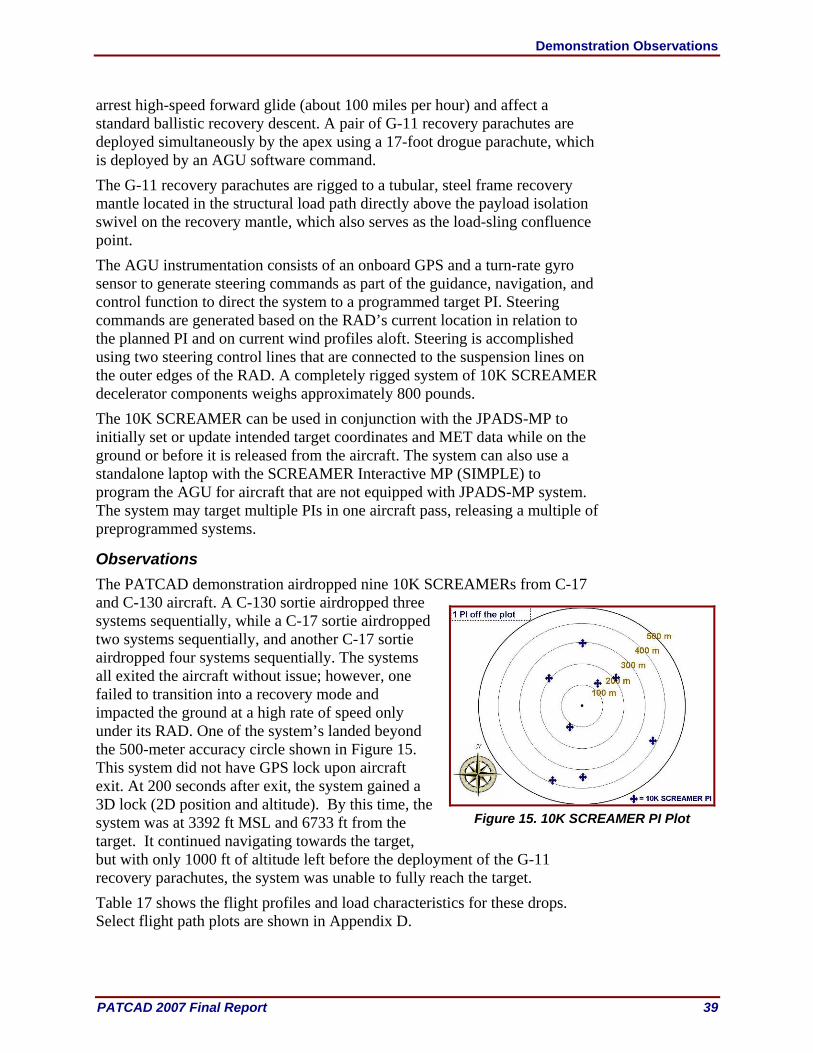
Demonstration Observations
PATCAD 2007 Final Report 39
arrest high-speed forward glide (about 100 miles per hour) and affect a standard ballistic recovery descent. A pair of G-11 recovery parachutes are deployed simultaneously by the apex using a 17-foot drogue parachute, which is deployed by an AGU software command. The G-11 recovery parachutes are rigged to a tubular, steel frame recovery mantle located in the structural load path directly above the payload isolation swivel on the recovery mantle, which also serves as the load-sling confluence point. The AGU instrumentation consists of an onboard GPS and a turn-rate gyro sensor to generate steering commands as part of the guidance, navigation, and control function to direct the system to a programmed target PI. Steering commands are generated based on the RAD’s current location in relation to the planned PI and on current wind profiles aloft. Steering is accomplished using two steering control lines that are connected to the suspension lines on the outer edges of the RAD. A completely rigged system of 10K SCREAMER decelerator components weighs approximately 800 pounds. The 10K SCREAMER can be used in conjunction with the JPADS-MP to initially set or update intended target coordinates and MET data while on the ground or before it is released from the aircraft. The system can also use a standalone laptop with the SCREAMER Interactive MP (SIMPLE) to program the AGU for aircraft that are not equipped with JPADS-MP system. The system may target multiple PIs in one aircraft pass, releasing a multiple of preprogrammed systems.
Observations The PATCAD demonstration airdropped nine 10K SCREAMERs from C-17 and C-130 aircraft. A C-130 sortie airdropped three systems sequentially, while a C-17 sortie airdropped two systems sequentially, and another C-17 sortie airdropped four systems sequentially. The systems all exited the aircraft without issue; however, one failed to transition into a recovery mode and impacted the ground at a high rate of speed only under its RAD. One of the system’s landed beyond the 500-meter accuracy circle shown in Figure 15. This system did not have GPS lock upon aircraft exit. At 200 seconds after exit, the system gained a 3D lock (2D position and altitude). By this time, the system was at 3392 ft MSL and 6733 ft from the target. It continued navigating towards the target, but with only 1000 ft of altitude left before the deployment of the G-11 recovery parachutes, the system was unable to fully reach the target. Table 17 shows the flight profiles and load characteristics for these drops. Select flight path plots are shown in Appendix D.
Figure 15. 10K SCREAMER PI Plot
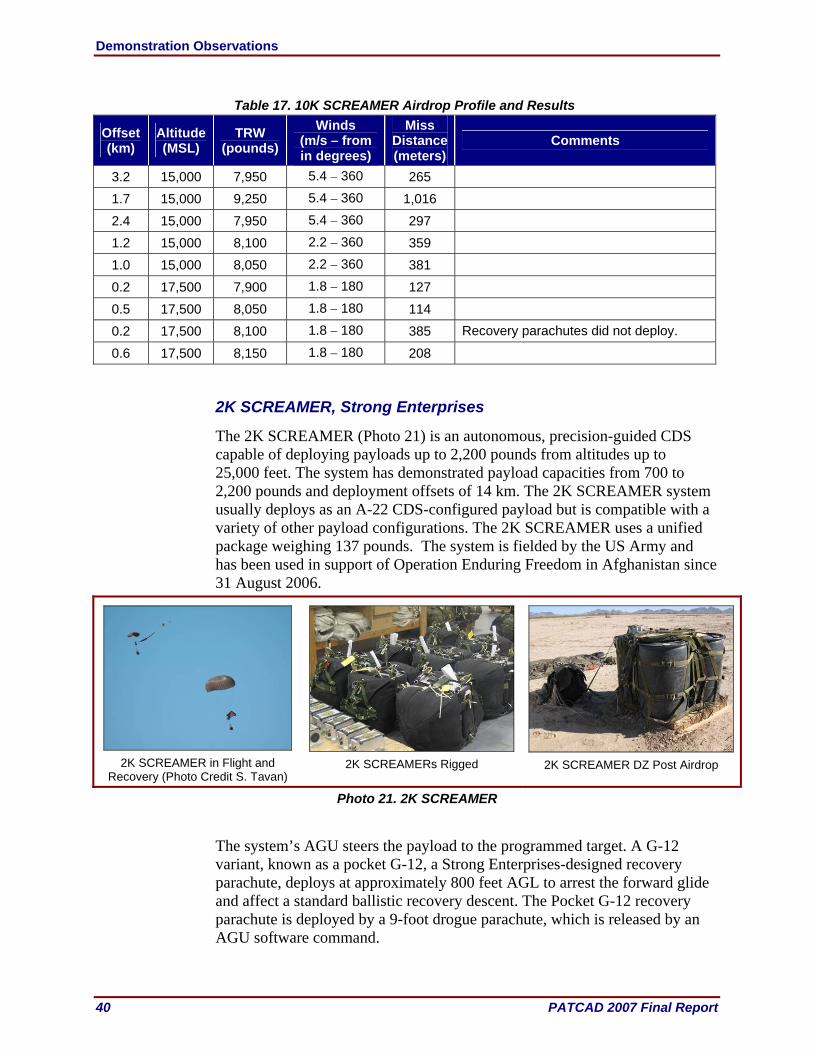
Demonstration Observations
40 PATCAD 2007 Final Report
Table 17. 10K SCREAMER Airdrop Profile and Results
Offset (km)
Altitude (MSL)
TRW (pounds)
Winds (m/s – from in degrees)
Miss Distance (meters)
Comments
3.2 15,000 7,950 5.4 – 360 265
1.7 15,000 9,250 5.4 – 360 1,016
2.4 15,000 7,950 5.4 – 360 297
1.2 15,000 8,100 2.2 – 360 359
1.0 15,000 8,050 2.2 – 360 381
0.2 17,500 7,900 1.8 – 180 127
0.5 17,500 8,050 1.8 – 180 114
0.2 17,500 8,100 1.8 – 180 385 Recovery parachutes did not deploy.
0.6 17,500 8,150 1.8 – 180 208
2K SCREAMER, Strong Enterprises
The 2K SCREAMER (Photo 21) is an autonomous, precision-guided CDS capable of deploying payloads up to 2,200 pounds from altitudes up to 25,000 feet. The system has demonstrated payload capacities from 700 to 2,200 pounds and deployment offsets of 14 km. The 2K SCREAMER system usually deploys as an A-22 CDS-configured payload but is compatible with a variety of other payload configurations. The 2K SCREAMER uses a unified package weighing 137 pounds. The system is fielded by the US Army and has been used in support of Operation Enduring Freedom in Afghanistan since 31 August 2006.
2K SCREAMER in Flight and
Recovery (Photo Credit S. Tavan)
2K SCREAMERs Rigged 2K SCREAMER DZ Post Airdrop
Photo 21. 2K SCREAMER The system’s AGU steers the payload to the programmed target. A G-12 variant, known as a pocket G-12, a Strong Enterprises-designed recovery parachute, deploys at approximately 800 feet AGL to arrest the forward glide and affect a standard ballistic recovery descent. The Pocket G-12 recovery parachute is deployed by a 9-foot drogue parachute, which is released by an AGU software command.
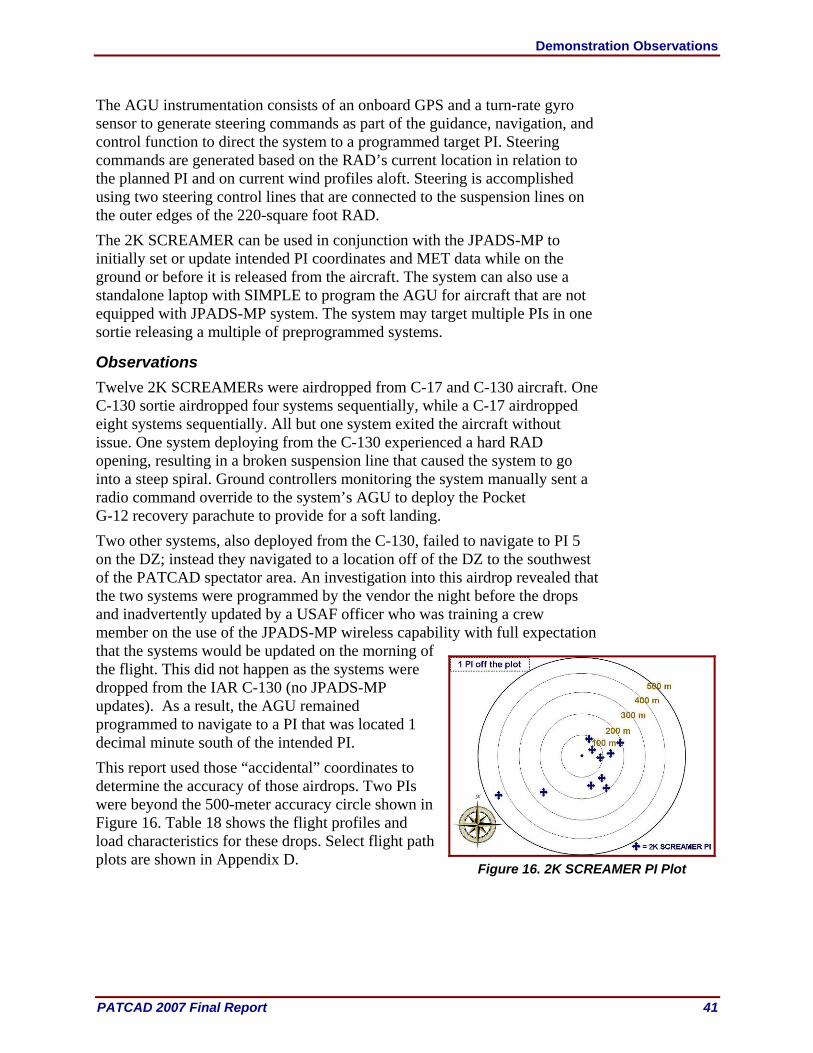
Demonstration Observations
PATCAD 2007 Final Report 41
The AGU instrumentation consists of an onboard GPS and a turn-rate gyro sensor to generate steering commands as part of the guidance, navigation, and control function to direct the system to a programmed target PI. Steering commands are generated based on the RAD’s current location in relation to the planned PI and on current wind profiles aloft. Steering is accomplished using two steering control lines that are connected to the suspension lines on the outer edges of the 220-square foot RAD. The 2K SCREAMER can be used in conjunction with the JPADS-MP to initially set or update intended PI coordinates and MET data while on the ground or before it is released from the aircraft. The system can also use a standalone laptop with SIMPLE to program the AGU for aircraft that are not equipped with JPADS-MP system. The system may target multiple PIs in one sortie releasing a multiple of preprogrammed systems.
Observations Twelve 2K SCREAMERs were airdropped from C-17 and C-130 aircraft. One C-130 sortie airdropped four systems sequentially, while a C-17 airdropped eight systems sequentially. All but one system exited the aircraft without issue. One system deploying from the C-130 experienced a hard RAD opening, resulting in a broken suspension line that caused the system to go into a steep spiral. Ground controllers monitoring the system manually sent a radio command override to the system’s AGU to deploy the Pocket G-12 recovery parachute to provide for a soft landing. Two other systems, also deployed from the C-130, failed to navigate to PI 5 on the DZ; instead they navigated to a location off of the DZ to the southwest of the PATCAD spectator area. An investigation into this airdrop revealed that the two systems were programmed by the vendor the night before the drops and inadvertently updated by a USAF officer who was training a crew member on the use of the JPADS-MP wireless capability with full expectation that the systems would be updated on the morning of the flight. This did not happen as the systems were dropped from the IAR C-130 (no JPADS-MP updates). As a result, the AGU remained programmed to navigate to a PI that was located 1 decimal minute south of the intended PI. This report used those “accidental” coordinates to determine the accuracy of those airdrops. Two PIs were beyond the 500-meter accuracy circle shown in Figure 16. Table 18 shows the flight profiles and load characteristics for these drops. Select flight path plots are shown in Appendix D.
Figure 16. 2K SCREAMER PI Plot

Demonstration Observations
42 PATCAD 2007 Final Report
Table 18. 2K SCREAMER Airdrop Profile and Results
Offset (km)
Altitude (MSL)
TRW (pounds)
Winds (m/s – from in degrees)
Miss Distance (meters)
Comments
4.3 17,500 1,678 6.3 – 358o 447
4.3 17,500 1,381 6.3 – 358o 254
Systems were accidentally programmed to coordinates south of the DZ; the missed distance is based on those coordinates.
5.8 17,500 2,275 6.3 – 358o 5,240
Suspension line broke; system became unstable, causing the system to oscillate. System’s G-12 parachute deployed manually with a radio signal from a ground station.
2.1 17,500 1,670 0.9 – 190o 133
1.6 17,500 2,270 0.9 – 190o 192
2.4 17,500 1,370 0.9 – 190o 141
1.7 17,500 1,976 0.9 – 190o 92
1.9 17,500 1,980 0.9 – 190o 194
1.8 17,500 1,665 0.9 – 190o 156
2.8 17,500 1,370 0.9 – 190o 65
1.5 17,500 2,266 0.9 – 190o 93
Sherpa 1200 and 2200, MMIST Incorporated The MMIST Sherpa (GPS-guided parafoil) (Photo 22) adds precision, reliability, and safety to bulk aerial resupply. With up to 10,000 pounds of cargo capacity and a horizontal standoff of over 15 km from an altitude of 25,000 feet in a zero-wind condition, the Sherpa is an invaluable asset for delivering humanitarian relief in areas of civil strife, search and rescue operations, and military resupply in hostile areas under unpredictable weather conditions. The Sherpa system was first utilized by the US Marine Corps in August 2004, and it continues to serve in theater, making it the most mature system available. MMIST has a basic ordering agreement and contract with the NSRDEC and has sold Sherpa systems to Canada and numerous NATO allies. The main goal for MMIST’s Sherpa team at PATCAD 2007 was to demonstrate the advances of the Sherpa-Guided Parachute Delivery System in the areas of reliability and accuracy.
Sherpa 1200/2200 Rigged
Sherpa 1200/2200 in Flight
(Photo Credit S. Tavan)
Sherpa 1200/2200 DZ Post Airdrop
Photo 22. Sherpa 1200/2200
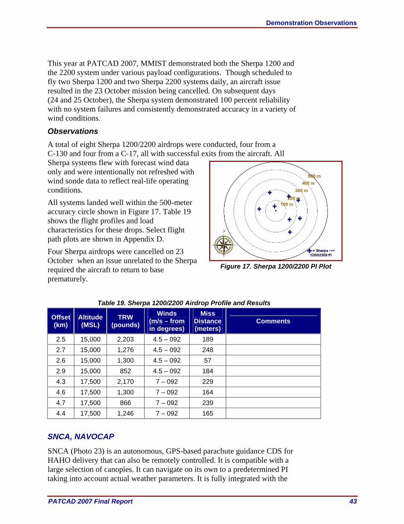
Demonstration Observations
PATCAD 2007 Final Report 43
This year at PATCAD 2007, MMIST demonstrated both the Sherpa 1200 and the 2200 system under various payload configurations. Though scheduled to fly two Sherpa 1200 and two Sherpa 2200 systems daily, an aircraft issue resulted in the 23 October mission being cancelled. On subsequent days (24 and 25 October), the Sherpa system demonstrated 100 percent reliability with no system failures and consistently demonstrated accuracy in a variety of wind conditions.
Observations A total of eight Sherpa 1200/2200 airdrops were conducted, four from a C-130 and four from a C-17, all with successful exits from the aircraft. All Sherpa systems flew with forecast wind data only and were intentionally not refreshed with wind sonde data to reflect real-life operating conditions. All systems landed well within the 500-meter accuracy circle shown in Figure 17. Table 19 shows the flight profiles and load characteristics for these drops. Select flight path plots are shown in Appendix D. Four Sherpa airdrops were cancelled on 23 October when an issue unrelated to the Sherpa required the aircraft to return to base prematurely.
Table 19. Sherpa 1200/2200 Airdrop Profile and Results
Offset (km)
Altitude (MSL)
TRW (pounds)
Winds (m/s – from in degrees)
Miss Distance (meters)
Comments
2.5 15,000 2,203 4.5 – 092 189 2.7 15,000 1,276 4.5 – 092 248 2.6 15,000 1,300 4.5 – 092 57 2.9 15,000 852 4.5 – 092 184 4.3 17,500 2,170 7 – 092 229 4.6 17,500 1,300 7 – 092 164 4.7 17,500 866 7 – 092 239 4.4 17,500 1,246 7 – 092 165
SNCA, NAVOCAP
SNCA (Photo 23) is an autonomous, GPS-based parachute guidance CDS for HAHO delivery that can also be remotely controlled. It is compatible with a large selection of canopies. It can navigate on its own to a predetermined PI taking into account actual weather parameters. It is fully integrated with the
Figure 17. Sherpa 1200/2200 PI Plot

Demonstration Observations
44 PATCAD 2007 Final Report
Operational Paratrooper Navigation System (OPNAS) that is patented by NAVOCAP. This allows jumpers to escort a payload, even at night or through solid layers of clouds, without collision risk utilizing the OPNAS “radar” capability. A remote control override allows manual control of the guidance system and can also be used as a beacon receiver to quickly locate the position of the load.
SNCA Rigged
SNCA in Flight
(Photo Credit S. Tavan) SNCA on DZ Post Airdrop
Photo 23. SNCA
SNCA has an operational altitude of up to 30,000 feet MSL and has an accuracy of better than 200 meters in 95 percent of the airdrops performed. Its offset is approximately 20 km in no wind conditions. Users may remotely control SNCA up to 2,000 meters away. A commercial-grade laptop computer (connected via cable or wirelessly) performs programming of the system.
Observations Four SNCA systems spread out over three IAR C-130 sorties were airdropped during PATCAD 2007. Each exited the aircraft without incident; however, one navigated a great distance off the DZ. It was later discovered that this system was not fully powered up. The switch was partially engaged, leaving the GPS and guidance unit powered on, but the flight control servos was still powered off. Two PIs were beyond the 500-meter accuracy circle shown in Figure 18. Table 20 shows the flight profiles and load characteristics for these drops.
Table 20. SNCA Airdrop Profile and Results
Offset (km)
Altitude (MSL)
TRW (pounds)
Winds (m/s – from in degrees)
Miss Distance (meters)
Comments
3.4 5,000 467 1.8 – 180 3,693 System navigated away from DZ; the system was not fully powered on before exiting from the aircraft.
0.9 5,000 465 2.2 – 300 542 2.4 5,000 466 0.4 – 300 332 2.5 5,000 454 0.4 – 300 128
Figure 18. SNCA PI Plot
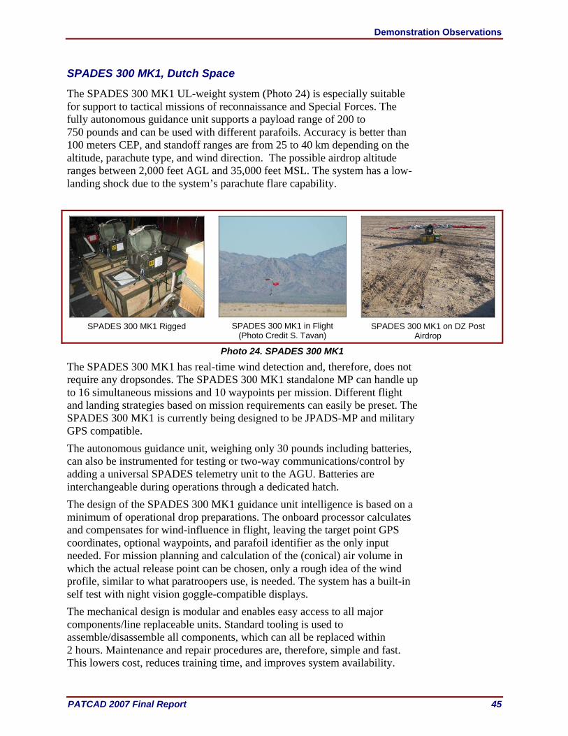
Demonstration Observations
PATCAD 2007 Final Report 45
SPADES 300 MK1, Dutch Space
The SPADES 300 MK1 UL-weight system (Photo 24) is especially suitable for support to tactical missions of reconnaissance and Special Forces. The fully autonomous guidance unit supports a payload range of 200 to 750 pounds and can be used with different parafoils. Accuracy is better than 100 meters CEP, and standoff ranges are from 25 to 40 km depending on the altitude, parachute type, and wind direction. The possible airdrop altitude ranges between 2,000 feet AGL and 35,000 feet MSL. The system has a low-landing shock due to the system’s parachute flare capability.
SPADES 300 MK1 Rigged
SPADES 300 MK1 in Flight
(Photo Credit S. Tavan)
SPADES 300 MK1 on DZ Post
Airdrop
Photo 24. SPADES 300 MK1
The SPADES 300 MK1 has real-time wind detection and, therefore, does not require any dropsondes. The SPADES 300 MK1 standalone MP can handle up to 16 simultaneous missions and 10 waypoints per mission. Different flight and landing strategies based on mission requirements can easily be preset. The SPADES 300 MK1 is currently being designed to be JPADS-MP and military GPS compatible. The autonomous guidance unit, weighing only 30 pounds including batteries, can also be instrumented for testing or two-way communications/control by adding a universal SPADES telemetry unit to the AGU. Batteries are interchangeable during operations through a dedicated hatch. The design of the SPADES 300 MK1 guidance unit intelligence is based on a minimum of operational drop preparations. The onboard processor calculates and compensates for wind-influence in flight, leaving the target point GPS coordinates, optional waypoints, and parafoil identifier as the only input needed. For mission planning and calculation of the (conical) air volume in which the actual release point can be chosen, only a rough idea of the wind profile, similar to what paratroopers use, is needed. The system has a built-in self test with night vision goggle-compatible displays. The mechanical design is modular and enables easy access to all major components/line replaceable units. Standard tooling is used to assemble/disassemble all components, which can all be replaced within 2 hours. Maintenance and repair procedures are, therefore, simple and fast. This lowers cost, reduces training time, and improves system availability.
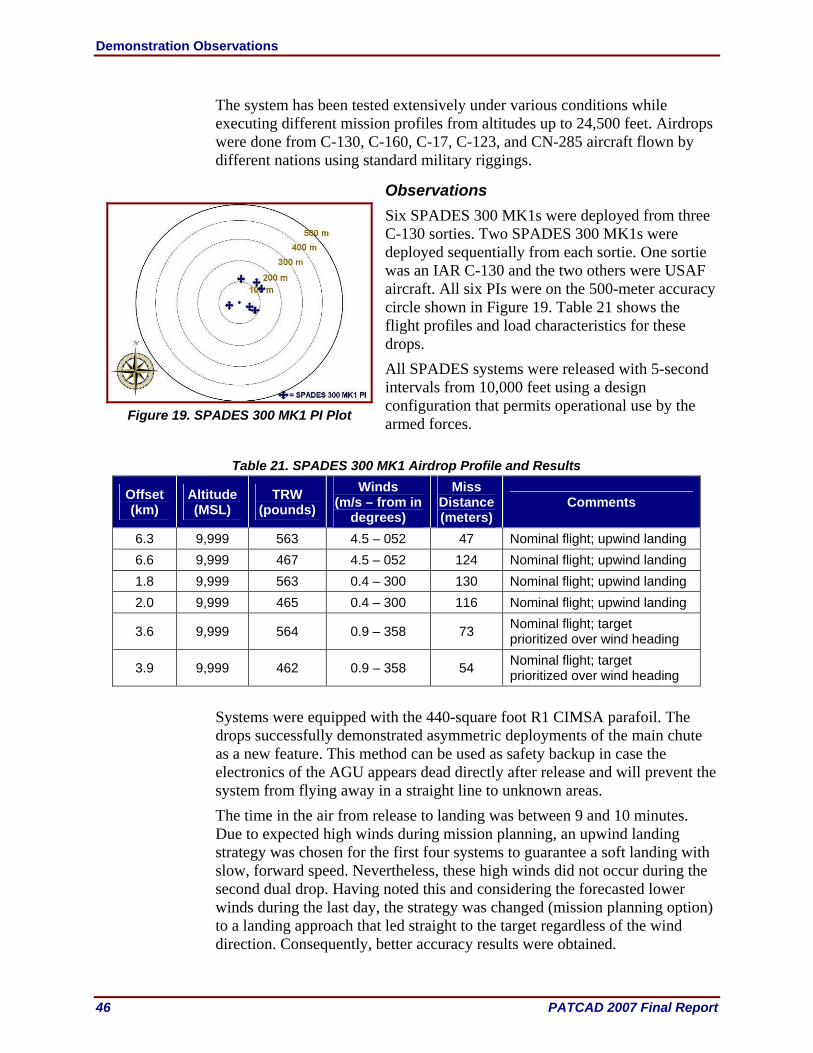
Demonstration Observations
46 PATCAD 2007 Final Report
The system has been tested extensively under various conditions while executing different mission profiles from altitudes up to 24,500 feet. Airdrops were done from C-130, C-160, C-17, C-123, and CN-285 aircraft flown by different nations using standard military riggings.
Observations Six SPADES 300 MK1s were deployed from three C-130 sorties. Two SPADES 300 MK1s were deployed sequentially from each sortie. One sortie was an IAR C-130 and the two others were USAF aircraft. All six PIs were on the 500-meter accuracy circle shown in Figure 19. Table 21 shows the flight profiles and load characteristics for these drops. All SPADES systems were released with 5-second intervals from 10,000 feet using a design configuration that permits operational use by the armed forces.
Table 21. SPADES 300 MK1 Airdrop Profile and Results
Offset (km)
Altitude (MSL)
TRW (pounds)
Winds (m/s – from in
degrees)
Miss Distance (meters)
Comments
6.3 9,999 563 4.5 – 052 47 Nominal flight; upwind landing 6.6 9,999 467 4.5 – 052 124 Nominal flight; upwind landing 1.8 9,999 563 0.4 – 300 130 Nominal flight; upwind landing 2.0 9,999 465 0.4 – 300 116 Nominal flight; upwind landing
3.6 9,999 564 0.9 – 358 73 Nominal flight; target prioritized over wind heading
3.9 9,999 462 0.9 – 358 54 Nominal flight; target prioritized over wind heading
Systems were equipped with the 440-square foot R1 CIMSA parafoil. The drops successfully demonstrated asymmetric deployments of the main chute as a new feature. This method can be used as safety backup in case the electronics of the AGU appears dead directly after release and will prevent the system from flying away in a straight line to unknown areas. The time in the air from release to landing was between 9 and 10 minutes. Due to expected high winds during mission planning, an upwind landing strategy was chosen for the first four systems to guarantee a soft landing with slow, forward speed. Nevertheless, these high winds did not occur during the second dual drop. Having noted this and considering the forecasted lower winds during the last day, the strategy was changed (mission planning option) to a landing approach that led straight to the target regardless of the wind direction. Consequently, better accuracy results were obtained.
Figure 19. SPADES 300 MK1 PI Plot

Demonstration Observations
PATCAD 2007 Final Report 47
All systems landed within 130 meters with a low dispersion rate. No malfunction or damage occurred.
SPADES 1000 MK1, Dutch Space
The SPADES 1000 MK1 (Photo 25) has a fully autonomous guidance unit that supports a payload range of 200 to 2,200 pounds with the possible use of different parafoils. Accuracy is better than 100 meters CEP, and standoff ranges are from 25 to 40 km depending on the altitude, parachute type, and wind direction. The possible airdrop altitudes range from 2,000 feet AGL to 35,000 feet MSL. The system has a low-landing shock due to the system’s parachute flare capability.
SPADES 1000 MK1 Rigged
SPADES 1000 MK1 in Flight
(Photo Credit S. Tavan)
SPADES 1000 MK1 on DZ
Post Airdrop
Photo 25. SPADES 1000 MK1
The SPADES 1000 MK1 has real-time wind detection, which eliminates the need for gathering wind data before the airdrop and, consequently, does not require an additional fly-by to make actual wind measurements prior to the drop. The SPADES 1000 MK1 standalone MP can handle up to 16 simultaneous missions and 10 waypoints per mission. Different flight and landing strategies based on mission requirements can easily be preset, and changes in target locations and waypoints can be entered minutes before the dropoff. The SPADES 1000 MK1 is also JPADS-MP and military GPS compatible. The autonomous guidance unit weighs 48 pounds, excluding the one or two batteries that weigh 8.5 pounds each, and can be removed/replaced in less than 10 seconds through a dedicated hatch. The external frame with parachute and payload interfaces provides adequate protection against unintentional blows or large static forces after landing (see the post-airdrop photo) or rough handling during transport. The frame can also be instrumented for testing or two-way communications/control. In fielded situations, the low-cost frame and batteries can easily be disposed of after landing, if needed, enabling the valuable AGU to be carried out by only one person. The design of the SPADES systems is based on principles of modularity, portability, ease of operations, ruggedness, and simple maintenance
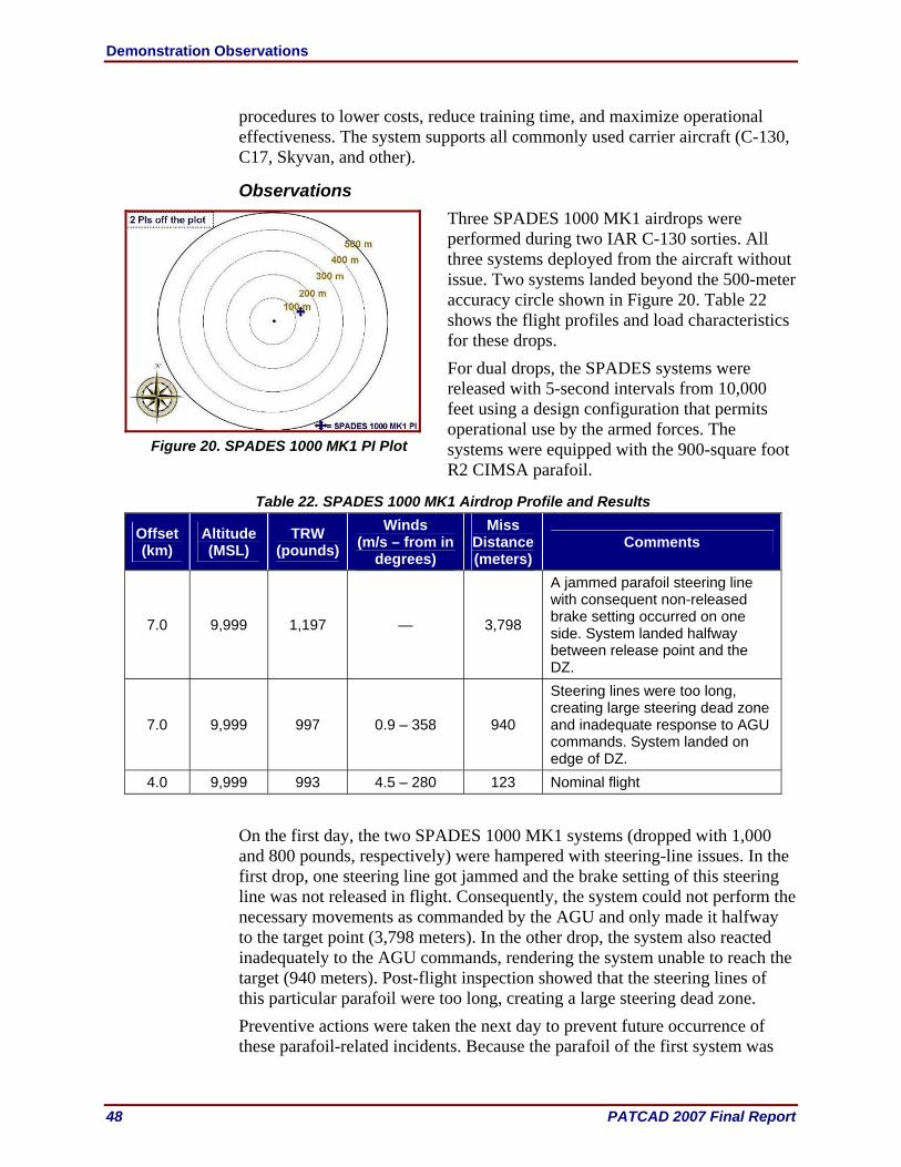
Demonstration Observations
48 PATCAD 2007 Final Report
procedures to lower costs, reduce training time, and maximize operational effectiveness. The system supports all commonly used carrier aircraft (C-130, C17, Skyvan, and other).
Observations Three SPADES 1000 MK1 airdrops were performed during two IAR C-130 sorties. All three systems deployed from the aircraft without issue. Two systems landed beyond the 500-meter accuracy circle shown in Figure 20. Table 22 shows the flight profiles and load characteristics for these drops. For dual drops, the SPADES systems were released with 5-second intervals from 10,000 feet using a design configuration that permits operational use by the armed forces. The systems were equipped with the 900-square foot R2 CIMSA parafoil.
Table 22. SPADES 1000 MK1 Airdrop Profile and Results
Offset (km)
Altitude (MSL)
TRW (pounds)
Winds (m/s – from in
degrees)
Miss Distance (meters)
Comments
7.0 9,999 1,197 — 3,798
A jammed parafoil steering line with consequent non-released brake setting occurred on one side. System landed halfway between release point and the DZ.
7.0 9,999 997 0.9 – 358 940
Steering lines were too long, creating large steering dead zone and inadequate response to AGU commands. System landed on edge of DZ.
4.0 9,999 993 4.5 – 280 123 Nominal flight
On the first day, the two SPADES 1000 MK1 systems (dropped with 1,000 and 800 pounds, respectively) were hampered with steering-line issues. In the first drop, one steering line got jammed and the brake setting of this steering line was not released in flight. Consequently, the system could not perform the necessary movements as commanded by the AGU and only made it halfway to the target point (3,798 meters). In the other drop, the system also reacted inadequately to the AGU commands, rendering the system unable to reach the target (940 meters). Post-flight inspection showed that the steering lines of this particular parafoil were too long, creating a large steering dead zone. Preventive actions were taken the next day to prevent future occurrence of these parafoil-related incidents. Because the parafoil of the first system was
Figure 20. SPADES 1000 MK1 PI Plot

Demonstration Observations
PATCAD 2007 Final Report 49
damaged beyond repair after landing in bushy terrain, only one system could be used for the demonstration on 25 October. The results of this last flight showed that, without any parafoil anomalies, the SPADES 1000 MK1 systems had returned to a nominal performance (123 meters). All AGUs performed without malfunction and survived all drops without any damage.
Paratroop Systems The results for the paratroop systems are presented not in terms of accuracy but whether the jumpers landed on the DZ. Other general observations are provided as well. The jumpers were provided a PI on the DZ to which to navigate, but they did not always choose to use it. The systems performing steering functions navigated the jumpers close to the PI, but at a given AGL, the jumper took over steering and many times navigated to a landing location (not necessarily the intended PI) of their own choosing. Other systems provided navigation information to the jumper, who in turn manually navigated to the DZ and picked their own PI. Other jumpers left the PIs well before data collectors could record that location.
MANPACK, MMIST Incorporated
The MANPACK system (Photo 26) is designed to deliver personnel to the DZ from high altitudes and significant lateral offsets. The chest-mounted system consists of a ram air canopy and GPS-based navigation system designed to fly the jumper on a predetermined flight path without manual controls. Once the jumper is away from the aircraft with the main chute open, the jumper attaches the steering lines to the risers, and the navigation system takes over the control of the flight. Prior to landing, the jumper detaches the steering lines from the risers using a quick-release system and manually lands the canopy. The parachute control unit is a similar but smaller unit as the one used in the MMIST Sherpa and can be integrated to any tandem container/harness parachute system available today.
MANPACK Demonstrated by
Paratrooper
MANPACK in Flight
(Photo Credit S. Tavan)
MANPACK
Photo 26. MANPACK
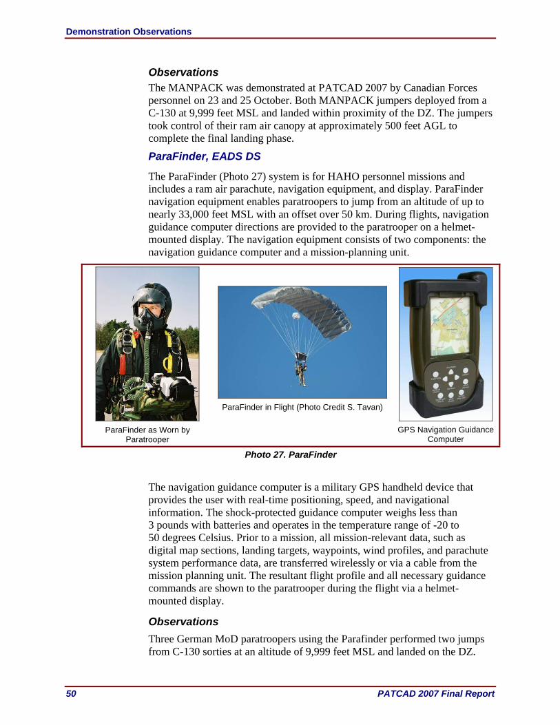
Demonstration Observations
50 PATCAD 2007 Final Report
Observations The MANPACK was demonstrated at PATCAD 2007 by Canadian Forces personnel on 23 and 25 October. Both MANPACK jumpers deployed from a C-130 at 9,999 feet MSL and landed within proximity of the DZ. The jumpers took control of their ram air canopy at approximately 500 feet AGL to complete the final landing phase.
ParaFinder, EADS DS
The ParaFinder (Photo 27) system is for HAHO personnel missions and includes a ram air parachute, navigation equipment, and display. ParaFinder navigation equipment enables paratroopers to jump from an altitude of up to nearly 33,000 feet MSL with an offset over 50 km. During flights, navigation guidance computer directions are provided to the paratrooper on a helmet-mounted display. The navigation equipment consists of two components: the navigation guidance computer and a mission-planning unit.
ParaFinder as Worn by
Paratrooper
ParaFinder in Flight (Photo Credit S. Tavan)
GPS Navigation Guidance
Computer
Photo 27. ParaFinder
The navigation guidance computer is a military GPS handheld device that provides the user with real-time positioning, speed, and navigational information. The shock-protected guidance computer weighs less than 3 pounds with batteries and operates in the temperature range of -20 to 50 degrees Celsius. Prior to a mission, all mission-relevant data, such as digital map sections, landing targets, waypoints, wind profiles, and parachute system performance data, are transferred wirelessly or via a cable from the mission planning unit. The resultant flight profile and all necessary guidance commands are shown to the paratrooper during the flight via a helmet-mounted display.
Observations Three German MoD paratroopers using the Parafinder performed two jumps from C-130 sorties at an altitude of 9,999 feet MSL and landed on the DZ.

Demonstration Observations
PATCAD 2007 Final Report 51
ParaNav, Rockwell Collins
ParaNav (Photo 28) is a low-weight, helmet-mounted parachutist navigation system. Its navigation pod is rigidly attached to the parachutist’s helmet, and a micro-display module is affixed to the parachutist’s goggles or blast shield. The display module is connected to the navigational pod via a thin cable assembly and connector.
ParaNav Worn by Paratrooper
ParaNav on Helmet and Viewer
Photo 28. ParaNav
Mission data are uploaded wirelessly to the ParaNav system from the JPADS-MP. With the loaded mission data, the embedded navigation software in the ParaNav provides the jumper with altitude, speed over ground, ground track/heading, GPS status, estimate arrival altitude, battery status, directions to and from a selected DZ, and other data displayed in a graphics/alpha-numeric format on the display module. The two-piece modular design of the system mounts onto standard helmets. It also has adjustable brightness for day/night operations. The controls of the helmet-mounted navigation system are Arctic-glove compatible. The system will provide for 4-hours of continuous operation on common commercial batteries.
Observations Four US Army paratroopers jumped from C-130 aircraft from an altitude of 9,999 feet MSL. The jump coincided with three MicroFly systems that were inadvertently airdropped from a C-130 when the aircraft loading ramp was lowered in preparation for the airdrop to the LaPosa DZ LAR. The distance was so great as to not allow the MicroFly payloads or the jumpers to reach the DZ. The ParaNav units performed correctly with a GPS lock in aircraft and under canopy.
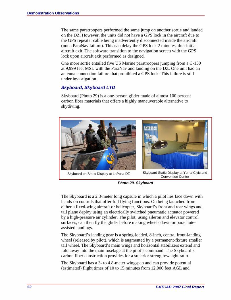
Demonstration Observations
52 PATCAD 2007 Final Report
The same paratroopers performed the same jump on another sortie and landed on the DZ. However, the units did not have a GPS lock in the aircraft due to the GPS repeater cable being inadvertently disconnected inside the aircraft (not a ParaNav failure). This can delay the GPS lock 2 minutes after initial aircraft exit. The software transition to the navigation screen with the GPS lock upon aircraft exit performed as designed. One more sortie entailed five US Marine paratroopers jumping from a C-130 at 9,999 feet MSL with the ParaNav and landing on the DZ. One unit had an antenna connection failure that prohibited a GPS lock. This failure is still under investigation.
Skyboard, Skyboard LTD
Skyboard (Photo 29) is a one-person glider made of almost 100 percent carbon fiber materials that offers a highly maneuverable alternative to skydiving.
Skyboard on Static Display at LaPosa DZ
Skyboard Static Display at Yuma Civic and
Convention Center
Photo 29. Skyboard The Skyboard is a 2.3-meter long capsule in which a pilot lies face down with hands-on controls that offer full flying functions. On being launched from either a fixed-wing aircraft or helicopter, Skyboard’s front and rear wings and tail plane deploy using an electrically switched pneumatic actuator powered by a high-pressure air cylinder. The pilot, using aileron and elevator control surfaces, can then fly the glider before making wheels down or parachute-assisted landings. The Skyboard’s landing gear is a spring-loaded, 8-inch, central front-landing wheel (released by pilot), which is augmented by a permanent-fixture smaller tail wheel. The Skyboard’s main wings and horizontal stabilizers extend and fold away into the main fuselage at the pilot’s command. The Skyboard’s carbon fiber construction provides for a superior strength/weight ratio. The Skyboard has a 3- to 4.8-meter wingspan and can provide potential (estimated) flight times of 10 to 15 minutes from 12,000 feet AGL and
Demonstration Observations
PATCAD 2007 Final Report 53
55 minutes from 25,000 feet AGL. Drop heights for the Skyboard are from 10,000 to 35,000 feet AGL. Additional equipment includes an altimeter, flight speed indicator, rate-of-descent indictor, and ballistic parachute for emergency deployment.
Observations The Skyboard was presented at PATCAD 2007 as a static display at the Yuma Civic and Convention Center. The Skyboard was planned to be dropped during PATCAD 2007, however approvals to drop the Skyboard system were not ready at the time of the PATCAD.

Demonstration Observations
54 PATCAD 2007 Final Report
This page is intentionally blank.

Appendix A: Load Plan
PATCAD 2007 Final Report A–1
Appendix A: Load Plan
Load Plan Drop Item MSL (feet) Test Remarks PI
Tuesday, 23 October 2007 Lift 1: IAR C-130
1 x SNCA 5,000 1 x ramp bundle at 340 pounds 4
CADS + 4 x Jumpers 9,999 Ramp bundle at 350 pounds + HAHO jumpers 5
MANPACK 9,999 Canadian Forces HAHO jumpers 0 3 x EADS Jumpers 9,999 German MoD HAHO jumpers 0
2 x Skyboard Jumpers 9,999 HAHO jumpers 0
2 x SPADES 300 9,999 Ramp bundle (1 at 400 and 300 pounds) 3
2 x SPADES 1000 + 1 x Dragon Train Sonde 9,999 2 x CDSs (1 each at 1,000 and
800 pounds) 2
2 x Dragon Trains 9,999 2 x ramp bundles (each at 350 pounds) 5
Lift 2: USAF C-130
3 x PANTHER 500s 9,999 3 x ramp bundles (each at 400 pounds) 4
PANTHER 2000 9,999 CDS at 2,200 pounds 4 2 x Sondes 9,999 2 at 2 pounds 6
2 x LCADS High-velocity 9,999 2 x CDSs (1 each at 1,800 and 1,600 pounds) 5
3 x FireFlys 9,999 4 x CDSs (2 each at 1,000 and 700 pounds) 3
Lift 3: USAF C-130 2 x Sondes 12,000 6
3 x MicroFlys + 4 x Jumpers using ParaNav 12,000
3 x ramp bundles (1 at 400 pounds and 2 at 350 pounds) + US Army
HAHO jumpers 3
Lift 4: IAR C-130 2 x Sondes 17,500 6
4x 2K SCREAMERs 17,500 8 x CDSs (1 each at 2,100, 1,800, 1,500, and 1,200 pounds) 2, 3
4 x AGAS 17,500 8 x CDSs (1 each at 2,000, 1,900, 1,800, and 1,700 pounds) 2, 4
Lift 5: USAF C-130
3 x Mosquitos (Opposite Doors) 9,999 Door bundles ( 1 each at 150, 75, 20, and 5 pounds) 3
30K MegaFly + Natick Wind Pack 17,500 1 at 25,000 pounds 6

Appendix A: Load Plan
A–2 PATCAD 2007 Final Report
Load Plan Drop Item MSL (feet) Test Remarks PI
Wednesday, 24 October 2007 Lift 1: IAR C-130
1 x SNCA 9,999 1 x ramp bundle at 340 pounds 5
2 x SPADES 300 9,999 2 x ramp bundles (1 each at 400 and 300 pounds) 3
3 x PANTHER 500s 9,999 3 x ramp bundles (each at 400 pounds) 4
Lift 2: USAF C-130 2 x Sondes 17,500 6
3 x 10K SCREAMERs 17,500 8,550, 7,100, and 7,100 pounds 5 Lift 3: USAF C-17
2 x Sondes 17,500 6 2 x 10K SCREAMERs 17,500 7,200 and 7,350 pounds 5
8 x FireFlys 17,500 8 x CDSs (4 at 2,200 pounds, 2 at
1,800 pounds, and 2 at 1,500 pounds)
2, 3
4 x Sherpa (2 x 1200s and 2 x 2200s) 17,500
4 x CDSs (1 at 2,000 pounds, 2 at 1,100 pounds, and 1 at 700
pounds) 2
3 x Onyx 300 17,500 3 x door bundles (1 at 150 pounds and 2 at 100 pounds) 4
Lift 4: USAF C-130 30K MegaFly 17,500 25,000 pounds 6
Thursday, 25 October 2007 – VIP Day Day Lift 1: IAR
2 x SNCA 5,000 4
CADS + 4 x Jumpers 9,999 Ramp bundle at 350 pounds + HAHO jumpers 5
MANPACK 9,999 Canadian Forces HAHO jumpers 0 3 x EADS DS Jumpers 9,999 German MoD HAHO jumpers 0
2 x SPADES 300 9,999 2 x ramp bundles (1 each at 400 and 300 pounds) 3
1 x SPADES 1000 + Dragon Train Sonde 9,999 2 x CDSs (one each at 1,000 and
800 pounds) 2
1 x Dragon Train 9,999 2 x ramp bundles (each at 350 pounds) 5
Lift 2: USAF C-130 2 x Sondes 17,500 6
3 x Onyx 300s 17,500 3 x door bundles (1 at 150 pounds and 2 at 100 pounds) 4
4 x Onyx 500s 17,500 3 x ramp bundles (one each at 350, 325, and 250 pounds) 4

Appendix A: Load Plan
PATCAD 2007 Final Report A–3
Load Plan Drop Item MSL (feet) Test Remarks PI
4 x Sherpa (2 x 1200s and 2 x 2200s) 17,500
4 x CDSs (1 at 2,000 pounds, 2 at 1,100 pounds, and 1 at 700
pounds) 2
Lift 3: USAF C-130
3 x PANTHER 500s 9,999 3 x ramp bundles (each at 400 pounds) 4
3 x MicroFlys + 4 x ParaNav Jumpers 9,999
3 x ramp bundles (1 each at 400, 350, and 350 pounds) + HAHO
jumpers 3
5 x ParaNav Jumpers 9,999 US Marine Static-line jumpers 0 2 x Sondes 17,500 2 at 2 pounds 6
1 x 26-foot Ringslot 17,500 CDS at 1,800 pounds 2
4 x FireFlys 17,500 4 x CDSs (2 each at 2,200 and 1,500 pounds) 3
Lift 4: USAF C-17 2 x Sondes 17,500 6
4 x 10K SCREAMERs 17,500 7050, 7300, 7250, 7300 pounds 5
8 x 2K SCREAMERs 17,500 8 x CDSs (2 each at 2,100, 1,800, 1,500, and 1,200 pounds) 2, 3
8 x AGASs 17,500 8 x CDSs (1 each at 1,500, 1,400, 1,300, 1,200, 1,100, 1,000, 900,
and 800 pounds) 2, 4
Lift #5: USAF C-130
3 x Mosquitos (Opposite Doors) 9,999 8 x door bundles (2 each at 150, 75, 20, and 5 pounds) 3
30K MegaFly + Natick Wind Pack 17,500 1 at 25,000 pounds 6

Appendix A: Load Plan
A–4 PATCAD 2007 Final Report
This page is intentionally blank. .

Appendix B: Aloft MET Data
PATCAD 2007 Final Report B–1
Appendix B: Aloft MET Data All weather balloons collecting MET data on each morning of the demonstrations were released from the following YPG location: Station Name: ROBY Latitude: 33.36 Longitude: -114.27 Altitude: 1,322 feet
10/23/2007 (0500L) 10/23/2007; 0500L Flight; Launch Time: 12:22 UTC
Altitude (feet
above MSL)
Press (MB)
Temperature (°F) RH (%) Dew Point
(°F) Air
Density (g/m3)
Wind Direction (degrees)
Wind Speed (kts)
1,322 977.7 54.0 16 9.1 1,191.09 336.0 6.9 1,400 974.9 62.8 16 15.5 1,167.53 10.2 9.9 1,500 971.5 65.0 14 14.0 1,158.55 7.8 10.5 1,600 968.0 65.4 13 12.6 1,153.63 7.6 10.8 1,700 964.6 65.6 12 12.1 1,149.18 8.7 10.5 1,800 961.1 65.6 12 11.8 1,145.05 11.9 9.7 1,900 957.7 65.8 12 11.8 1,140.58 16.7 9.1 2,000 954.4 65.5 12 11.6 1,137.26 21.4 8.9 2,100 950.9 65.0 12 11.4 1,134.11 26.3 9.4 2,200 947.5 64.7 12 11.4 1,130.82 29.9 10.3 2,300 944.1 64.7 12 11.4 1,126.77 32.2 11.5 2,400 940.8 64.7 12 11.5 1,122.76 33.3 12.8 2,500 937.5 64.5 12 11.6 1,119.11 33.8 13.8 2,600 934.1 64.5 12 11.8 1,115.18 34.7 14.7 2,700 930.8 64.4 13 11.8 1,111.41 36.8 15.4 2,800 927.4 64.0 13 11.8 1,108.29 40.1 15.9 2,900 924.1 64.1 13 12.3 1,104.01 44.0 16.4 3,000 920.8 64.9 13 13.2 1,098.39 47.4 16.6 3,100 917.5 65.2 13 12.9 1,093.77 50.4 16.7 3,200 914.3 65.1 12 12.2 1,090.19 52.8 16.6 3,300 911.0 64.6 12 11.5 1,087.27 54.4 16.2 3,400 907.8 64.2 12 11.1 1,084.36 55.8 15.8 3,500 904.5 63.7 13 11.4 1,081.37 57.5 15.3 3,600 901.3 63.2 13 11.2 1,078.63 59.3 14.8
°F = degrees Fahrenheit; g/m3 = grams per cubic meter; MB = millibars, RH = relative humidity; UTC = universal time coordinated

Appendix B: Aloft MET Data
B–2 PATCAD 2007 Final Report
10/23/2007; 0500L Flight; Launch Time: 12:22 UTC Altitude
(feet above MSL)
Press (MB)
Temperature (°F) RH (%) Dew Point
(°F) Air
Density (g/m3)
Wind Direction (degrees)
Wind Speed (kts)
3,700 898.0 62.7 13 10.7 1,075.82 60.5 14.6 3,800 894.9 62.3 13 10.3 1,072.75 60.8 14.6 3,900 891.6 62.2 12 8.6 1,069.33 60.3 14.7 4,000 888.4 61.8 12 7.8 1,066.13 59.4 14.6 4,100 885.3 61.4 12 7.8 1,063.19 58.8 14.4 4,200 882.1 61.1 12 7.8 1,060.07 59.0 14.0 4,300 878.9 60.7 12 7.8 1,057.02 59.7 13.8 4,400 875.8 60.4 12 7.7 1,053.96 59.2 14.0 4,500 872.6 60.2 12 7.9 1,050.52 57.5 14.5 4,600 869.5 60.0 12 7.4 1,047.12 56.5 15.5 4,700 866.4 60.2 12 7.9 1,043.03 56.7 16.5 4,800 863.3 60.3 13 9.0 1,039.02 57.3 17.2 4,900 860.1 59.9 13 9.0 1,035.98 58.4 17.9 5,000 857.1 59.6 13 9.1 1,032.88 59.7 18.2 5,100 854.0 59.1 14 9.2 1,030.10 61.7 18.3 5,200 850.8 58.6 14 9.9 1,027.28 64.0 18.4 5,300 847.8 58.1 15 10.1 1,024.66 66.9 18.5 5,400 844.7 57.6 15 10.2 1,021.87 70.2 18.5 5,500 841.8 57.1 16 10.9 1,019.16 73.8 18.5 5,600 838.6 57.1 17 12.4 1,015.33 77.5 18.3 5,700 835.7 57.5 15 10.9 1,011.07 80.1 18.1 5,800 832.6 57.5 15 10.5 1,007.34 81.7 17.9 5,900 829.6 57.7 16 11.4 1,003.41 82.5 17.6 6,000 826.6 57.3 16 11.2 1,000.49 83.5 17.5 6,100 823.6 56.8 15 10.3 997.85 85.1 17.3 6,200 820.7 56.3 16 10.5 995.13 86.0 16.8 6,300 817.6 55.9 16 10.2 992.24 85.9 16.4 6,400 814.7 55.4 16 9.9 989.72 84.5 16.2 6,500 811.7 54.9 16 9.9 986.94 82.5 16.1 6,600 808.8 54.7 16 10.1 983.88 78.9 16.3 6,700 805.9 54.6 17 10.1 980.50 75.4 16.6 6,800 802.9 54.6 18 12.1 976.76 72.0 16.8 6,900 800.0 54.6 19 13.1 973.21 70.8 16.9 7,000 797.1 54.8 19 13.7 969.33 71.1 17.0 7,100 794.2 54.5 19 13.5 966.22 70.7 17.1 7,200 791.4 54.3 19 13.4 963.26 69.1 17.1

Appendix B: Aloft MET Data
PATCAD 2007 Final Report B–3
10/23/2007; 0500L Flight; Launch Time: 12:22 UTC Altitude
(feet above MSL)
Press (MB)
Temperature (°F) RH (%) Dew Point
(°F) Air
Density (g/m3)
Wind Direction (degrees)
Wind Speed (kts)
7,300 788.5 55.0 19 13.9 958.34 66.4 17.2 7,400 785.5 55.1 19 13.9 954.52 62.9 17.5 7,500 782.7 54.8 19 13.7 951.76 58.3 17.9 7,600 779.9 54.5 20 13.7 948.90 55.0 18.2 7,700 777.0 54.2 20 13.7 945.79 52.2 18.4 7,800 774.2 54.0 21 14.6 942.71 48.9 18.5 7,900 771.4 54.0 20 14.5 939.29 44.8 18.2 8,000 768.6 54.2 20 14.0 935.52 40.8 17.5 8,100 765.8 54.2 20 13.7 932.15 37.7 16.6 8,200 763.0 54.8 19 13.9 927.76 36.0 15.9 8,300 760.2 55.0 19 13.8 923.98 36.4 15.3 8,400 757.5 55.5 19 13.6 919.82 38.5 15.1 8,500 754.7 55.8 18 13.0 915.93 41.6 15.4 8,600 752.1 55.3 18 12.6 913.46 44.4 16.1 8,700 749.3 55.2 19 13.9 910.24 46.4 17.0 8,800 746.6 55.1 19 13.7 907.13 47.9 17.7 8,900 743.8 55.0 19 13.6 904.09 49.3 18.0 9,000 741.1 55.2 19 13.4 900.32 50.4 18.0 9,100 738.5 55.2 18 12.7 897.15 51.3 17.9 9,200 735.8 54.9 18 11.7 894.49 51.6 18.0 9,300 733.0 54.6 18 11.6 891.71 51.2 18.3 9,400 730.5 54.4 17 10.8 888.91 50.2 18.7 9,500 727.8 54.2 17 10.8 886.07 48.6 19.0 9,600 725.1 53.7 18 10.8 883.67 46.8 19.2 9,700 722.6 53.2 18 10.8 881.44 45.5 19.3 9,800 719.9 52.9 18 10.6 878.62 44.7 19.2 9,900 717.2 52.3 18 10.5 876.32 43.3 19.1
10,000 714.6 51.8 19 10.3 874.05 41.4 19.1 10,100 712.0 51.5 19 10.1 871.29 39.9 19.4 10,200 709.4 51.3 19 9.9 868.52 39.1 19.6 10,300 706.8 51.2 19 9.8 865.56 39.1 19.9 10,400 704.3 50.7 19 9.6 863.32 39.6 20.1 10,500 701.6 50.3 19 9.4 860.79 40.5 20.2 10,600 699.1 49.9 19 9.6 858.29 41.3 20.4 10,700 696.5 49.5 20 10.3 855.62 42.1 20.5 10,800 694.0 49.1 21 10.7 853.36 43.0 20.7

Appendix B: Aloft MET Data
B–4 PATCAD 2007 Final Report
10/23/2007; 0500L Flight; Launch Time: 12:22 UTC Altitude
(feet above MSL)
Press (MB)
Temperature (°F) RH (%) Dew Point
(°F) Air
Density (g/m3)
Wind Direction (degrees)
Wind Speed (kts)
10,900 691.4 48.6 21 10.2 851.01 44.3 20.8 11,000 688.9 48.2 22 10.7 848.40 46.1 20.8 11,100 686.4 47.9 22 10.8 845.83 47.9 20.7 11,200 683.8 47.6 22 11.0 843.16 49.3 20.2 11,300 681.3 47.4 23 11.7 840.39 49.9 19.1 11,400 678.7 47.6 23 11.7 836.97 49.6 17.8 11,500 676.3 47.6 22 10.9 833.96 48.3 16.5 11,600 673.8 47.6 22 10.3 830.95 46.2 15.9 11,700 671.3 47.6 22 10.3 827.81 43.9 15.8 11,800 668.8 47.2 22 10.6 825.38 41.8 15.9 11,900 666.3 47.0 22 10.6 822.68 40.2 15.8 12,000 663.9 46.7 23 10.8 820.19 39.4 15.3 12,100 661.5 46.7 22 9.8 817.19 39.5 14.4 12,200 659.0 46.7 20 8.3 814.15 40.0 13.7 12,300 656.6 47.0 20 7.9 810.68 39.9 13.3 12,400 654.2 46.8 19 6.9 808.12 39.1 13.5 12,500 651.7 46.3 20 7.1 805.88 37.8 13.7 12,600 649.3 46.0 20 6.8 803.47 36.7 13.9 12,700 646.9 45.7 19 5.3 800.95 35.2 13.9 12,800 644.5 45.4 19 5.3 798.51 33.5 13.9 12,900 642.2 44.9 19 4.9 796.42 31.9 13.8 13,000 639.7 44.5 19 4.6 793.95 30.5 13.7 13,100 637.4 44.0 19 4.2 791.80 29.5 13.4 13,200 635.0 43.8 19 3.8 789.22 28.3 12.9 13,300 632.7 43.4 19 3.4 786.87 26.4 12.5 13,400 630.3 43.6 18 2.6 783.66 24.0 12.5 13,500 628.0 43.6 17 1.7 780.84 21.7 12.9 13,600 625.7 43.4 16 0.7 778.34 19.8 13.4 13,700 623.3 42.9 16 0.4 776.18 17.3 13.7 13,800 621.1 42.5 16 -0.1 773.94 14.1 13.8 13,900 618.7 42.2 17 0.0 771.54 11.1 13.7 14,000 616.4 42.0 17 -0.1 768.95 9.3 13.8 14,100 614.1 41.6 17 -0.5 766.73 9.0 14.1 14,200 611.8 41.1 17 -0.9 764.62 9.7 14.4 14,300 609.5 40.7 17 -1.3 762.34 10.2 14.7 14,400 607.3 40.1 17 -1.6 760.46 10.1 15.1

Appendix B: Aloft MET Data
PATCAD 2007 Final Report B–5
10/23/2007; 0500L Flight; Launch Time: 12:22 UTC Altitude
(feet above MSL)
Press (MB)
Temperature (°F) RH (%) Dew Point
(°F) Air
Density (g/m3)
Wind Direction (degrees)
Wind Speed (kts)
14,500 605.0 39.7 17 -2.1 758.14 9.7 15.4 14,600 602.7 39.3 17 -2.3 755.96 9.1 15.6 14,700 600.4 38.8 17 -2.6 753.82 8.6 15.7 14,800 598.2 38.6 16 -3.3 751.45 8.4 15.6 14,900 595.9 38.2 16 -4.1 749.14 8.7 15.3 15,000 593.7 37.7 16 -4.3 747.24 9.3 15.1 15,100 591.5 37.2 16 -4.7 745.06 10.2 15.0 15,200 589.3 36.8 15 -5.9 742.97 11.3 14.8 15,300 587.1 36.3 16 -5.9 740.89 12.6 14.8 15,400 584.9 36.0 16 -6.3 738.63 14.0 14.8 15,500 582.6 35.4 16 -6.6 736.55 15.3 14.9 15,600 580.4 34.9 16 -6.8 734.60 16.4 14.9 15,700 578.2 34.4 16 -7.0 732.56 17.3 14.8 15,800 576.0 34.0 16 -7.1 730.37 18.1 14.5 15,900 573.8 33.5 17 -7.1 728.42 18.9 14.1 16,000 571.7 33.1 17 -7.2 726.16 19.2 13.7 16,100 569.5 32.6 17 -7.7 724.15 19.2 13.4 16,200 567.3 32.1 17 -8.0 722.11 19.6 13.3 16,300 565.1 31.7 17 -8.2 719.92 21.2 13.3 16,400 563.0 31.1 17 -8.4 718.02 24.0 13.1 16,500 560.8 30.8 17 -8.8 715.77 27.0 13.0 16,600 558.8 30.5 16 -10.1 713.64 28.8 13.0 16,700 556.6 30.1 16 -10.8 711.38 28.3 13.4 16,800 554.5 29.7 16 -11.3 709.24 25.4 13.9 16,900 552.4 29.6 15 -12.5 706.82 20.9 14.5 17,000 550.3 30.2 13 -15.8 703.31 16.4 15.1 17,100 548.1 31.1 10 -20.6 699.42 12.4 15.4 17,200 546.1 31.0 8 -23.6 696.87 9.2 15.5 17,300 544.0 30.7 8 -24.6 694.66 6.3 15.7 17,400 541.9 30.6 7 -25.7 692.07 3.4 16.1 17,500 539.9 30.2 7 -26.6 690.07 1.0 16.6 17,600 537.8 29.8 7 -27.2 687.98 359.0 17.0 17,700 535.7 29.5 7 -27.7 685.83 357.4 17.3 17,800 533.6 29.0 7 -28.1 683.89 356.1 17.5 17,900 531.6 28.5 7 -28.4 681.97 354.8 17.6 18,000 529.6 28.0 7 -28.6 680.10 353.7 17.8

Appendix B: Aloft MET Data
B–6 PATCAD 2007 Final Report
10/23/2007 (0600L) 10/23/2007; 0600L Flight; Launch Time: 13:23 UTC
Altitude (feet
above MSL)
Press (MB)
Temperature (°F) RH (%) Dew Point
(°F) Air
Density (g/m3)
Wind Direction (degrees)
Wind Speed (kts)
1,322 977.6 55.3 16 9.2 1,188.05 344.0 4.8 1,400 974.9 58.2 16 12.2 1,178.00 1.9 8.0 1,500 971.3 62.7 15 14.3 1,163.47 5.8 10.6 1,600 967.9 66.5 13 13.9 1,151.01 8.7 12.6 1,700 964.4 67.1 12 12.7 1,145.66 10.9 13.8 1,800 961.1 67.2 12 12.1 1,141.44 12.9 14.4 1,900 957.6 66.7 12 11.9 1,138.39 15.1 14.6 2,000 954.2 66.4 12 11.8 1,135.11 17.9 14.7 2,100 950.7 65.8 12 11.8 1,132.10 21.8 14.8 2,200 947.4 65.8 12 12.1 1,128.22 25.6 15.0 2,300 944.1 65.8 12 12.4 1,124.30 29.8 15.1 2,400 940.7 65.9 12 12.8 1,119.90 34.3 15.0 2,500 937.4 67.3 13 14.1 1,112.90 38.5 14.8 2,600 934.0 67.8 12 13.0 1,107.90 42.6 14.3 2,700 930.8 67.3 12 12.6 1,105.19 45.6 13.8 2,800 927.5 67.0 12 12.0 1,101.88 48.3 13.3 2,900 924.1 67.2 11 10.4 1,097.65 50.2 13.1 3,000 920.9 66.8 10 8.5 1,094.57 51.4 13.1 3,100 917.6 66.5 10 7.8 1,091.33 51.9 13.3 3,200 914.4 66.1 10 7.2 1,088.38 51.5 13.8 3,300 911.1 65.9 9 6.7 1,084.92 50.4 14.5 3,400 907.8 65.6 9 6.2 1,081.75 49.6 15.2 3,500 904.6 65.4 10 6.8 1,078.34 49.1 15.9 3,600 901.4 65.1 10 7.8 1,075.00 49.1 16.2 3,700 898.2 65.0 11 9.3 1,071.31 49.2 16.3 3,800 894.9 65.0 12 10.3 1,067.38 49.6 16.2 3,900 891.7 64.7 11 9.8 1,064.24 50.6 16.1 4,000 888.6 64.0 11 9.1 1,061.76 52.6 16.1 4,100 885.4 63.6 11 8.9 1,058.92 55.8 16.3 4,200 882.3 63.6 12 10.1 1,055.18 59.4 16.7 4,300 879.1 63.2 12 10.7 1,052.13 63.1 17.4 4,400 876.0 62.6 13 10.5 1,049.55 66.6 18.0 4,500 872.8 62.3 13 10.9 1,046.26 69.1 18.6 4,600 869.7 62.6 15 14.0 1,041.88 70.7 19.0
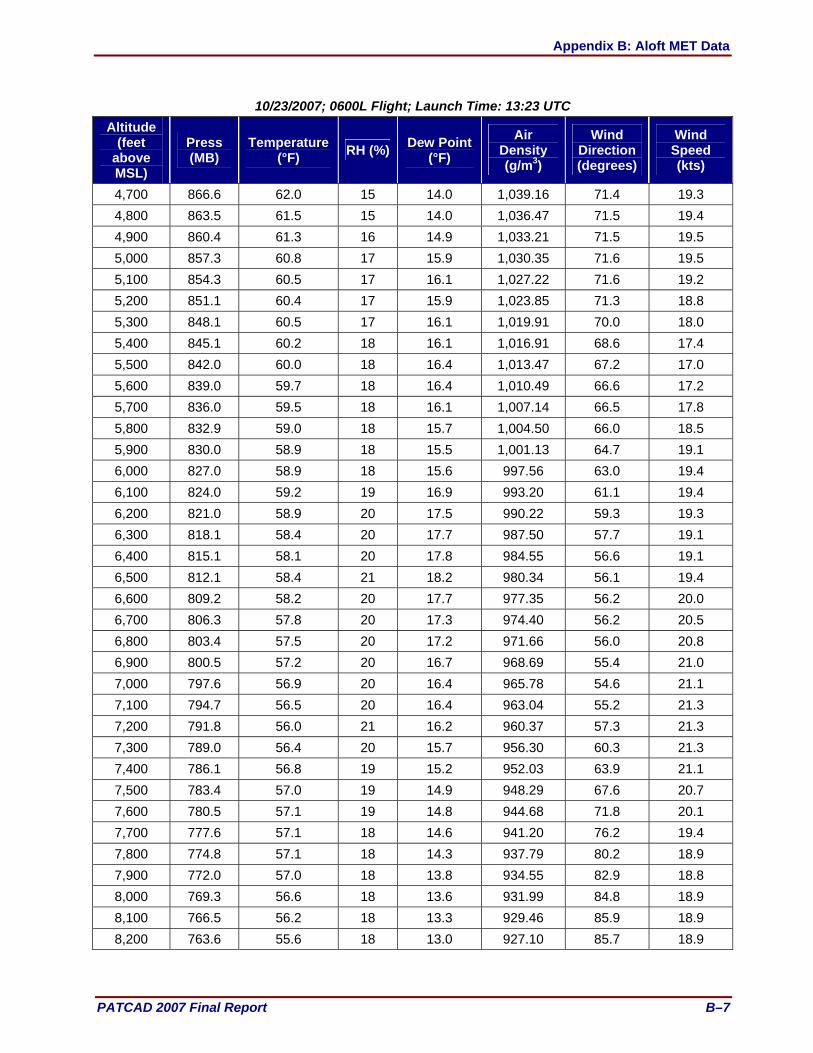
Appendix B: Aloft MET Data
PATCAD 2007 Final Report B–7
10/23/2007; 0600L Flight; Launch Time: 13:23 UTC Altitude
(feet above MSL)
Press (MB)
Temperature(°F) RH (%) Dew Point
(°F) Air
Density (g/m3)
Wind Direction (degrees)
Wind Speed (kts)
4,700 866.6 62.0 15 14.0 1,039.16 71.4 19.3 4,800 863.5 61.5 15 14.0 1,036.47 71.5 19.4 4,900 860.4 61.3 16 14.9 1,033.21 71.5 19.5 5,000 857.3 60.8 17 15.9 1,030.35 71.6 19.5 5,100 854.3 60.5 17 16.1 1,027.22 71.6 19.2 5,200 851.1 60.4 17 15.9 1,023.85 71.3 18.8 5,300 848.1 60.5 17 16.1 1,019.91 70.0 18.0 5,400 845.1 60.2 18 16.1 1,016.91 68.6 17.4 5,500 842.0 60.0 18 16.4 1,013.47 67.2 17.0 5,600 839.0 59.7 18 16.4 1,010.49 66.6 17.2 5,700 836.0 59.5 18 16.1 1,007.14 66.5 17.8 5,800 832.9 59.0 18 15.7 1,004.50 66.0 18.5 5,900 830.0 58.9 18 15.5 1,001.13 64.7 19.1 6,000 827.0 58.9 18 15.6 997.56 63.0 19.4 6,100 824.0 59.2 19 16.9 993.20 61.1 19.4 6,200 821.0 58.9 20 17.5 990.22 59.3 19.3 6,300 818.1 58.4 20 17.7 987.50 57.7 19.1 6,400 815.1 58.1 20 17.8 984.55 56.6 19.1 6,500 812.1 58.4 21 18.2 980.34 56.1 19.4 6,600 809.2 58.2 20 17.7 977.35 56.2 20.0 6,700 806.3 57.8 20 17.3 974.40 56.2 20.5 6,800 803.4 57.5 20 17.2 971.66 56.0 20.8 6,900 800.5 57.2 20 16.7 968.69 55.4 21.0 7,000 797.6 56.9 20 16.4 965.78 54.6 21.1 7,100 794.7 56.5 20 16.4 963.04 55.2 21.3 7,200 791.8 56.0 21 16.2 960.37 57.3 21.3 7,300 789.0 56.4 20 15.7 956.30 60.3 21.3 7,400 786.1 56.8 19 15.2 952.03 63.9 21.1 7,500 783.4 57.0 19 14.9 948.29 67.6 20.7 7,600 780.5 57.1 19 14.8 944.68 71.8 20.1 7,700 777.6 57.1 18 14.6 941.20 76.2 19.4 7,800 774.8 57.1 18 14.3 937.79 80.2 18.9 7,900 772.0 57.0 18 13.8 934.55 82.9 18.8 8,000 769.3 56.6 18 13.6 931.99 84.8 18.9 8,100 766.5 56.2 18 13.3 929.46 85.9 18.9 8,200 763.6 55.6 18 13.0 927.10 85.7 18.9
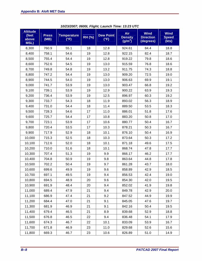
Appendix B: Aloft MET Data
B–8 PATCAD 2007 Final Report
10/23/2007; 0600L Flight; Launch Time: 13:23 UTC Altitude
(feet above MSL)
Press (MB)
Temperature (°F) RH (%) Dew Point
(°F) Air
Density (g/m3)
Wind Direction (degrees)
Wind Speed (kts)
8,300 760.9 55.1 18 12.8 924.61 84.4 18.8 8,400 758.1 54.6 19 12.8 922.15 82.4 18.7 8,500 755.4 54.4 19 12.8 919.22 79.8 18.6 8,600 752.6 54.5 19 13.0 915.59 76.8 18.6 8,700 749.8 54.8 19 13.2 911.75 74.3 18.8 8,800 747.2 54.4 19 13.0 909.20 72.5 19.0 8,900 744.5 54.0 19 13.0 906.63 69.9 19.1 9,000 741.7 53.9 19 13.0 903.47 66.8 19.2 9,100 739.1 53.9 19 12.9 900.22 63.9 19.3 9,200 736.4 53.9 19 12.5 896.97 60.3 19.2 9,300 733.7 54.3 18 11.9 893.02 56.3 18.9 9,400 731.0 54.4 18 11.4 889.50 53.5 18.3 9,500 728.3 54.6 17 11.0 886.01 51.8 17.6 9,600 725.7 54.4 17 10.8 883.20 50.8 17.0 9,700 723.1 53.9 17 10.6 880.77 50.4 16.7 9,800 720.4 53.5 17 10.3 878.21 50.3 16.7 9,900 717.9 52.9 18 10.1 876.10 50.4 16.9 10,000 715.3 52.5 18 10.3 873.64 50.3 17.2 10,100 712.6 52.0 18 10.1 871.18 49.6 17.5 10,200 710.0 51.6 18 10.1 868.74 47.8 17.7 10,300 707.4 51.3 19 9.9 866.17 46.2 17.7 10,400 704.8 50.9 19 9.8 863.64 44.8 17.8 10,500 702.2 50.4 19 9.7 861.28 43.7 18.0 10,600 699.6 49.9 19 9.6 858.89 42.9 18.5 10,700 697.1 49.5 19 9.4 856.53 42.4 19.0 10,800 694.5 48.9 20 9.6 854.30 42.0 19.5 10,900 691.9 48.4 20 9.4 852.02 41.9 19.8 11,000 689.4 47.9 21 9.4 849.78 42.9 20.0 11,100 686.9 47.4 21 9.2 847.52 44.9 19.9 11,200 684.4 47.0 21 9.1 845.05 47.6 19.7 11,300 681.9 46.9 21 9.1 842.16 50.4 19.5 11,400 679.4 46.5 21 8.9 839.68 52.9 18.8 11,500 676.8 46.5 22 9.4 836.48 54.1 17.9 11,600 674.3 46.7 22 10.1 833.09 53.9 16.7 11,700 671.8 46.9 23 11.0 829.68 52.6 15.6 11,800 669.3 46.7 23 10.6 826.89 51.0 14.9

Appendix B: Aloft MET Data
PATCAD 2007 Final Report B–9
10/23/2007; 0600L Flight; Launch Time: 13:23 UTC Altitude
(feet above MSL)
Press (MB)
Temperature(°F) RH (%) Dew Point
(°F) Air
Density (g/m3)
Wind Direction (degrees)
Wind Speed (kts)
11,900 666.9 46.9 22 9.6 823.59 50.2 14.5 12,000 664.4 46.6 21 9.2 820.87 49.5 14.2 12,100 662.0 46.3 22 9.2 818.44 48.0 13.8 12,200 659.5 45.8 22 9.2 816.21 44.9 12.9 12,300 657.1 45.6 23 9.6 813.49 42.1 12.3 12,400 654.7 45.6 23 9.6 810.57 38.9 11.6 12,500 652.3 45.4 22 9.1 807.86 35.7 10.9 12,600 649.8 45.4 22 8.5 804.90 33.8 10.6 12,700 647.4 45.2 22 8.1 802.17 33.8 10.7 12,800 645.0 44.9 22 8.2 799.75 34.3 11.0 12,900 642.7 44.5 21 7.1 797.45 34.3 11.2 13,000 640.3 44.1 21 6.5 795.17 33.1 11.4 13,100 637.9 43.7 21 6.0 792.90 31.0 11.5 13,200 635.5 43.2 21 5.7 790.63 29.1 11.7 13,300 633.1 42.9 20 4.6 788.24 28.2 11.8 13,400 630.8 42.1 20 3.8 786.54 28.2 12.2 13,500 628.5 41.8 20 3.8 784.21 29.1 12.5 13,600 626.1 41.4 20 3.5 781.87 29.7 12.8 13,700 623.8 41.0 20 3.3 779.65 29.2 13.0 13,800 621.4 40.9 20 2.9 776.78 27.9 13.0 13,900 619.1 40.7 20 2.6 774.27 26.6 13.0 14,000 616.8 40.3 20 2.8 771.94 25.3 13.2 14100 614.5 39.9 21 2.9 769.69 23.9 13.6 14,200 612.2 39.5 21 2.4 767.46 22.4 14.2 14,300 609.9 39.5 20 1.4 764.65 21.3 14.9 14,400 607.6 39.5 19 0.3 761.80 20.6 15.5 14,500 605.4 39.2 18 -0.4 759.44 20.5 15.8 14,600 603.0 38.9 18 -0.9 756.86 20.6 15.8 14,700 600.8 38.8 17 -2.0 754.36 21.1 15.5 14,800 598.5 38.4 17 -2.6 752.01 21.8 15.1 14,900 596.3 38.0 17 -2.8 749.83 22.7 14.7 15,000 594.1 37.6 17 -3.1 747.75 23.9 14.3 15,100 591.8 37.1 17 -4.1 745.61 25.3 13.9 15,200 589.6 36.7 17 -4.3 743.41 26.3 13.4 15,300 587.4 36.4 17 -4.6 741.09 26.5 13.0 15,400 585.1 36.0 17 -5.2 738.82 25.6 12.7

Appendix B: Aloft MET Data
B–10 PATCAD 2007 Final Report
10/23/2007; 0600L Flight; Launch Time: 13:23 UTC Altitude
(feet above MSL)
Press (MB)
Temperature (°F) RH (%) Dew Point
(°F) Air
Density (g/m3)
Wind Direction (degrees)
Wind Speed (kts)
15,500 582.9 35.7 16 -5.9 736.59 24.5 12.6 15,600 580.8 35.2 16 -6.1 734.51 23.7 12.4 15,700 578.6 34.8 16 -6.4 732.43 23.2 12.3 15,800 576.4 34.3 16 -6.8 730.42 22.6 12.3 15,900 574.2 34.0 16 -7.1 728.07 22.1 12.2 16,000 572.1 33.7 16 -7.7 725.86 21.6 12.3 16,100 569.9 33.2 16 -8.2 723.82 21.4 12.7 16,200 567.6 32.7 16 -8.4 721.72 21.1 13.3 16,300 565.5 32.2 16 -8.6 719.64 20.8 14.0 16,400 563.4 31.9 16 -9.1 717.47 20.7 14.7 16,500 561.2 31.7 15 -10.6 714.93 21.1 15.0 16,600 559.0 31.2 15 -11.6 712.96 21.9 14.8 16,700 557.0 30.8 15 -11.8 710.89 22.5 14.4 16,800 554.8 30.5 15 -12.2 708.69 23.0 14.3 16,900 552.7 30.1 14 -13.1 706.51 23.5 14.6 17,000 550.6 29.8 14 -13.7 704.30 24.3 15.3 17,100 548.5 29.5 14 -14.3 702.07 25.1 16.1 17,200 546.4 29.4 13 -15.5 699.50 25.1 16.3 17,300 544.3 29.9 11 -18.1 696.08 23.7 15.8 17,400 542.2 29.8 10 -19.9 693.71 22.1 15.1 17,500 540.2 29.6 10 -21.4 691.39 18.4 13.8 17,600 538.2 29.9 8 -24.3 688.29 12.0 12.2 17,700 536.0 30.5 6 -28.0 684.89 7.5 11.7 17,800 534.0 30.2 6 -29.8 682.67 5.0 11.8 17,900 531.9 29.7 6 -30.6 680.69 3.8 12.1 18,000 529.9 29.4 6 -31.2 678.59 2.9 12.5
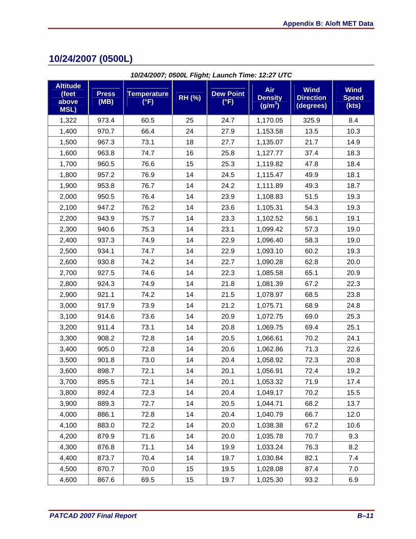
Appendix B: Aloft MET Data
PATCAD 2007 Final Report B–11
10/24/2007 (0500L) 10/24/2007; 0500L Flight; Launch Time: 12:27 UTC
Altitude (feet
above MSL)
Press (MB)
Temperature(°F) RH (%) Dew Point
(°F) Air
Density (g/m3)
Wind Direction (degrees)
Wind Speed (kts)
1,322 973.4 60.5 25 24.7 1,170.05 325.9 8.4 1,400 970.7 66.4 24 27.9 1,153.58 13.5 10.3 1,500 967.3 73.1 18 27.7 1,135.07 21.7 14.9 1,600 963.8 74.7 16 25.8 1,127.77 37.4 18.3 1,700 960.5 76.6 15 25.3 1,119.82 47.8 18.4 1,800 957.2 76.9 14 24.5 1,115.47 49.9 18.1 1,900 953.8 76.7 14 24.2 1,111.89 49.3 18.7 2,000 950.5 76.4 14 23.9 1,108.83 51.5 19.3 2,100 947.2 76.2 14 23.6 1,105.31 54.3 19.3 2,200 943.9 75.7 14 23.3 1,102.52 56.1 19.1 2,300 940.6 75.3 14 23.1 1,099.42 57.3 19.0 2,400 937.3 74.9 14 22.9 1,096.40 58.3 19.0 2,500 934.1 74.7 14 22.9 1,093.10 60.2 19.3 2,600 930.8 74.2 14 22.7 1,090.28 62.8 20.0 2,700 927.5 74.6 14 22.3 1,085.58 65.1 20.9 2,800 924.3 74.9 14 21.8 1,081.39 67.2 22.3 2,900 921.1 74.2 14 21.5 1,078.97 68.5 23.8 3,000 917.9 73.9 14 21.2 1,075.71 68.9 24.8 3,100 914.6 73.6 14 20.9 1,072.75 69.0 25.3 3,200 911.4 73.1 14 20.8 1,069.75 69.4 25.1 3,300 908.2 72.8 14 20.5 1,066.61 70.2 24.1 3,400 905.0 72.8 14 20.6 1,062.86 71.3 22.6 3,500 901.8 73.0 14 20.4 1,058.92 72.3 20.8 3,600 898.7 72.1 14 20.1 1,056.91 72.4 19.2 3,700 895.5 72.1 14 20.1 1,053.32 71.9 17.4 3,800 892.4 72.3 14 20.4 1,049.17 70.2 15.5 3,900 889.3 72.7 14 20.5 1,044.71 68.2 13.7 4,000 886.1 72.8 14 20.4 1,040.79 66.7 12.0 4,100 883.0 72.2 14 20.0 1,038.38 67.2 10.6 4,200 879.9 71.6 14 20.0 1,035.78 70.7 9.3 4,300 876.8 71.1 14 19.9 1,033.24 76.3 8.2 4,400 873.7 70.4 14 19.7 1,030.84 82.1 7.4 4,500 870.7 70.0 15 19.5 1,028.08 87.4 7.0 4,600 867.6 69.5 15 19.7 1,025.30 93.2 6.9

Appendix B: Aloft MET Data
B–12 PATCAD 2007 Final Report
10/24/2007; 0500L Flight; Launch Time: 12:27 UTC Altitude
(feet above MSL)
Press (MB)
Temperature (°F) RH (%) Dew Point
(°F) Air
Density (g/m3)
Wind Direction (degrees)
Wind Speed (kts)
4,700 864.5 69.9 15 20.0 1,020.96 95.3 7.8 4,800 861.5 69.7 15 19.9 1,017.69 94.2 9.4 4,900 858.4 69.7 15 20.1 1,014.06 93.6 10.5 5,000 855.4 69.1 15 19.9 1,011.76 93.0 11.7 5,100 852.4 68.9 15 20.0 1,008.45 92.5 12.4 5,200 849.4 68.4 16 19.9 1,005.95 92.2 12.7 5,300 846.4 67.9 16 19.8 1,003.24 92.1 12.8 5,400 843.4 67.4 16 19.5 1,000.73 92.8 12.7 5,500 840.4 66.9 16 19.7 998.08 94.5 12.6 5,600 837.3 66.5 17 19.7 995.18 97.1 12.6 5,700 834.4 65.9 17 19.8 992.77 100.1 13.1 5,800 831.4 65.4 17 19.9 990.17 101.7 14.0 5,900 828.5 65.1 17 19.9 987.27 102.3 14.4 6,000 825.6 64.3 18 19.5 985.34 103.0 14.7 6,100 822.7 63.8 18 19.3 982.76 103.8 15.5 6,200 819.7 63.4 18 19.4 979.94 103.9 16.7 6,300 816.7 63.0 19 19.7 977.07 104.7 18.0 6,400 813.7 62.7 19 19.9 974.22 106.2 19.9 6,500 810.9 62.1 19 20.0 971.76 107.0 21.3 6,600 808.0 61.7 20 20.2 969.00 107.2 21.8 6,700 805.1 61.3 20 20.4 966.29 107.5 21.8 6,800 802.2 60.7 21 20.2 963.95 108.5 21.7 6,900 799.4 60.3 21 20.2 961.26 109.6 21.8 7,000 796.4 59.9 21 20.0 958.55 109.3 22.0 7,100 793.6 59.3 21 19.9 956.21 107.9 22.3 7,200 790.7 58.7 22 19.9 953.79 106.4 22.7 7,300 787.9 58.2 22 19.7 951.35 105.9 23.3 7,400 785.1 57.8 22 19.7 948.59 107.0 23.4 7,500 782.3 57.8 23 20.0 945.26 107.5 22.8 7,600 779.3 57.5 23 19.8 942.20 106.4 21.9 7,700 776.5 57.1 23 19.9 939.65 104.0 21.1 7,800 773.8 56.8 23 19.8 936.85 99.9 20.2 7,900 771.0 56.6 23 19.3 933.82 95.9 19.5 8,000 768.2 56.3 23 19.1 930.93 92.9 19.0 8,100 765.4 55.9 23 18.8 928.41 91.0 18.6 8,200 762.6 55.7 23 18.8 925.25 90.7 18.2

Appendix B: Aloft MET Data
PATCAD 2007 Final Report B–13
10/24/2007; 0500L Flight; Launch Time: 12:27 UTC Altitude
(feet above MSL)
Press (MB)
Temperature(°F) RH (%) Dew Point
(°F) Air
Density (g/m3)
Wind Direction (degrees)
Wind Speed (kts)
8,300 759.8 55.7 23 18.5 921.99 92.9 17.9 8,400 757.1 55.3 23 18.1 919.37 95.2 17.8 8,500 754.3 55.3 23 17.9 916.09 96.1 16.6 8,600 751.7 55.0 23 17.7 913.39 98.7 15.1 8,700 748.9 55.8 21 16.2 908.64 105.0 14.2 8,800 746.2 56.4 18 14.0 904.45 109.8 14.0 8,900 743.5 56.2 18 12.7 901.51 112.3 13.1 9,000 740.8 56.0 17 12.3 898.58 114.6 11.7 9,100 738.1 55.9 17 11.6 895.66 114.9 11.0 9,200 735.5 55.7 17 11.0 892.79 113.4 11.2 9,300 732.7 55.1 17 10.8 890.45 112.1 11.7 9,400 730.1 54.6 17 10.7 888.09 111.1 12.1 9,500 727.5 54.2 17 10.7 885.73 109.4 12.4 9,600 724.8 53.7 17 10.5 883.25 107.6 12.6 9,700 722.2 53.2 18 10.5 880.98 107.6 13.0 9,800 719.6 52.6 18 10.5 878.76 111.4 12.6 9,900 716.9 52.8 18 10.0 875.16 118.9 11.6 10,000 714.3 52.4 18 9.6 872.67 125.0 11.1 10,100 711.7 52.1 17 9.2 870.07 128.7 11.0 10,200 709.1 51.6 18 9.1 867.61 129.7 10.9 10,300 706.4 51.2 18 9.1 865.12 128.9 10.7 10,400 703.9 50.6 18 8.9 862.99 128.5 10.7 10,500 701.3 50.3 18 8.7 860.40 128.5 11.0 10,600 698.7 49.9 18 8.5 857.84 126.2 10.9 10,700 696.2 49.5 18 8.3 855.41 120.3 10.1 10,800 693.6 49.4 18 8.1 852.52 114.8 9.4 10,900 691.1 49.0 18 7.9 849.97 108.3 9.1 11,000 688.6 48.7 18 7.6 847.56 102.0 9.1 11,100 686.0 48.3 18 7.4 844.96 100.2 9.3 11,200 683.5 47.8 19 7.3 842.64 99.1 9.7 11,300 681.0 47.5 19 7.1 840.07 100.1 10.5 11,400 678.5 47.0 19 6.9 837.81 99.6 11.1 11,500 676.0 46.5 19 6.8 835.61 98.0 11.2 11,600 673.5 46.1 19 6.7 833.07 96.2 11.3 11,700 671.0 46.0 20 6.7 830.33 95.1 11.9 11,800 668.5 46.0 19 6.0 827.29 97.2 12.5
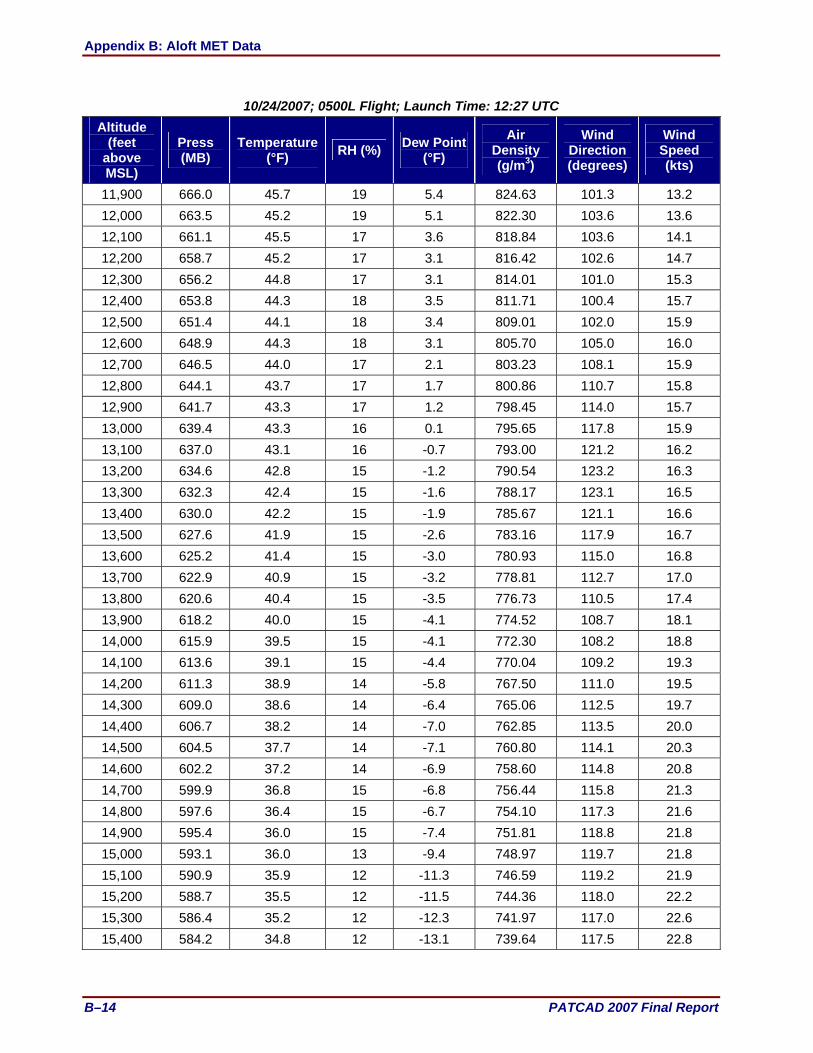
Appendix B: Aloft MET Data
B–14 PATCAD 2007 Final Report
10/24/2007; 0500L Flight; Launch Time: 12:27 UTC Altitude
(feet above MSL)
Press (MB)
Temperature (°F) RH (%) Dew Point
(°F) Air
Density (g/m3)
Wind Direction (degrees)
Wind Speed (kts)
11,900 666.0 45.7 19 5.4 824.63 101.3 13.2 12,000 663.5 45.2 19 5.1 822.30 103.6 13.6 12,100 661.1 45.5 17 3.6 818.84 103.6 14.1 12,200 658.7 45.2 17 3.1 816.42 102.6 14.7 12,300 656.2 44.8 17 3.1 814.01 101.0 15.3 12,400 653.8 44.3 18 3.5 811.71 100.4 15.7 12,500 651.4 44.1 18 3.4 809.01 102.0 15.9 12,600 648.9 44.3 18 3.1 805.70 105.0 16.0 12,700 646.5 44.0 17 2.1 803.23 108.1 15.9 12,800 644.1 43.7 17 1.7 800.86 110.7 15.8 12,900 641.7 43.3 17 1.2 798.45 114.0 15.7 13,000 639.4 43.3 16 0.1 795.65 117.8 15.9 13,100 637.0 43.1 16 -0.7 793.00 121.2 16.2 13,200 634.6 42.8 15 -1.2 790.54 123.2 16.3 13,300 632.3 42.4 15 -1.6 788.17 123.1 16.5 13,400 630.0 42.2 15 -1.9 785.67 121.1 16.6 13,500 627.6 41.9 15 -2.6 783.16 117.9 16.7 13,600 625.2 41.4 15 -3.0 780.93 115.0 16.8 13,700 622.9 40.9 15 -3.2 778.81 112.7 17.0 13,800 620.6 40.4 15 -3.5 776.73 110.5 17.4 13,900 618.2 40.0 15 -4.1 774.52 108.7 18.1 14,000 615.9 39.5 15 -4.1 772.30 108.2 18.8 14,100 613.6 39.1 15 -4.4 770.04 109.2 19.3 14,200 611.3 38.9 14 -5.8 767.50 111.0 19.5 14,300 609.0 38.6 14 -6.4 765.06 112.5 19.7 14,400 606.7 38.2 14 -7.0 762.85 113.5 20.0 14,500 604.5 37.7 14 -7.1 760.80 114.1 20.3 14,600 602.2 37.2 14 -6.9 758.60 114.8 20.8 14,700 599.9 36.8 15 -6.8 756.44 115.8 21.3 14,800 597.6 36.4 15 -6.7 754.10 117.3 21.6 14,900 595.4 36.0 15 -7.4 751.81 118.8 21.8 15,000 593.1 36.0 13 -9.4 748.97 119.7 21.8 15,100 590.9 35.9 12 -11.3 746.59 119.2 21.9 15,200 588.7 35.5 12 -11.5 744.36 118.0 22.2 15,300 586.4 35.2 12 -12.3 741.97 117.0 22.6 15,400 584.2 34.8 12 -13.1 739.64 117.5 22.8
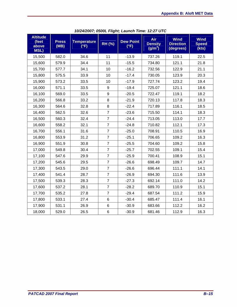
Appendix B: Aloft MET Data
PATCAD 2007 Final Report B–15
10/24/2007; 0500L Flight; Launch Time: 12:27 UTC Altitude
(feet above MSL)
Press (MB)
Temperature(°F) RH (%) Dew Point
(°F) Air
Density (g/m3)
Wind Direction (degrees)
Wind Speed (kts)
15,500 582.0 34.6 11 -13.9 737.26 119.1 22.5 15,600 579.9 34.4 11 -15.5 734.80 121.1 21.8 15,700 577.7 34.1 10 -16.2 732.56 122.9 21.1 15,800 575.5 33.9 10 -17.4 730.05 123.9 20.3 15,900 573.2 33.5 10 -17.9 727.74 123.2 19.4 16,000 571.1 33.5 9 -19.4 725.07 121.1 18.6 16,100 569.0 33.5 9 -20.5 722.47 119.1 18.2 16,200 566.8 33.2 8 -21.9 720.13 117.8 18.3 16,300 564.6 32.8 8 -22.4 717.89 116.1 18.5 16,400 562.5 32.6 7 -23.6 715.50 114.1 18.3 16,500 560.3 32.4 7 -24.4 713.05 113.0 17.7 16,600 558.2 32.1 7 -24.8 710.82 112.1 17.3 16,700 556.1 31.6 7 -25.0 708.91 110.5 16.9 16,800 553.9 31.2 7 -25.1 706.65 109.2 16.3 16,900 551.9 30.8 7 -25.5 704.60 109.2 15.8 17,000 549.8 30.4 7 -25.7 702.55 109.1 15.4 17,100 547.6 29.9 7 -25.9 700.41 108.9 15.1 17,200 545.6 29.5 7 -26.6 698.49 109.7 14.7 17,300 543.5 29.0 7 -26.6 696.44 111.1 14.1 17,400 541.4 28.7 7 -26.9 694.30 111.6 13.9 17,500 539.3 28.3 7 -27.3 692.14 111.0 14.2 17,600 537.2 28.1 7 -28.2 689.70 110.9 15.1 17,700 535.2 27.8 7 -29.4 687.54 111.2 15.9 17,800 533.1 27.4 6 -30.4 685.47 111.4 16.1 17,900 531.1 26.9 6 -30.9 683.66 112.2 16.2 18,000 529.0 26.5 6 -30.9 681.46 112.9 16.3

Appendix B: Aloft MET Data
B–16 PATCAD 2007 Final Report
10/25/2007 (0500L) 10/25/2007; 0500L Flight; Launch Time: 12:25 UTC
Altitude (feet
above MSL)
Press (MB)
Temperature (°F) RH (%) Dew Point
(°F) Air
Density (g/m3)
Wind Direction (degrees)
Wind Speed (kts)
1,322 968.4 56.0 26 21.3 1,174.47 306.1 2.4 1,400 965.7 70.1 24 31.8 1,139.07 356.6 3.3 1,500 962.4 71.7 21 29.6 1,131.95 353.9 3.4 1,600 958.9 74.2 19 29.0 1,122.74 348.6 2.8 1,700 955.6 76.0 18 29.1 1,114.99 323.4 1.3 1,800 952.3 79.2 16 29.6 1,104.58 248.0 0.9 1,900 949.0 80.0 15 28.7 1,099.22 199.0 1.8 2,000 945.7 79.8 15 28.1 1,095.80 181.0 2.6 2,100 942.4 79.8 15 28.1 1,092.01 164.0 3.2 2,200 939.2 79.8 15 28.3 1,088.20 148.5 3.8 2,300 935.9 79.4 15 28.1 1,085.21 139.5 4.5 2,400 932.7 79.2 15 28.1 1,081.88 134.0 5.4 2,500 929.4 78.7 15 27.9 1,079.06 130.8 6.6 2,600 926.3 78.5 16 28.1 1,075.74 129.1 8.0 2,700 923.0 78.6 16 28.3 1,071.75 128.3 9.3 2,800 919.9 78.7 16 28.3 1,067.92 128.0 10.5 2,900 916.6 78.5 16 28.1 1,064.66 128.3 11.5 3,000 913.5 78.0 16 27.8 1,061.88 128.8 12.3 3,100 910.2 77.4 16 27.7 1,059.31 129.3 12.8 3,200 907.1 77.0 16 27.6 1,056.52 129.8 13.1 3,300 903.9 76.5 16 27.5 1,053.79 130.1 13.2 3,400 900.9 76.0 16 27.4 1,051.14 130.3 13.1 3,500 897.6 75.4 17 27.2 1,048.56 130.3 12.8 3,600 894.5 75.0 17 27.2 1,045.71 130.2 12.3 3,700 891.3 74.6 17 27.2 1,042.82 129.8 11.7 3,800 888.3 74.5 17 27.2 1,039.42 129.1 11.2 3,900 885.2 74.1 17 27.1 1,036.70 128.1 10.9 4,000 882.1 74.2 17 27.2 1,032.70 127.0 10.7 4,100 879.0 74.1 17 26.9 1,029.38 126.0 10.8 4,200 876.0 73.8 17 26.9 1,026.31 125.2 10.8 4,300 872.9 73.4 18 26.7 1,023.52 124.5 10.8 4,400 869.8 73.0 18 26.3 1,020.74 123.7 10.7 4,500 866.7 72.5 18 26.0 1,018.03 122.4 10.5 4,600 863.7 72.1 17 25.7 1,015.27 121.1 10.2
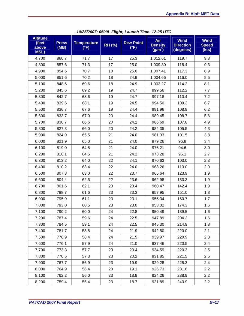
Appendix B: Aloft MET Data
PATCAD 2007 Final Report B–17
10/25/2007; 0500L Flight; Launch Time: 12:25 UTC Altitude
(feet above MSL)
Press (MB)
Temperature (°F) RH (%) Dew Point
(°F) Air
Density (g/m3)
Wind Direction (degrees)
Wind Speed (kts)
4,700 860.7 71.7 17 25.3 1,012.61 119.7 9.8 4,800 857.6 71.3 17 25.0 1,009.80 118.4 9.3 4,900 854.6 70.7 18 25.0 1,007.41 117.3 8.9 5,000 851.6 70.2 18 24.9 1,004.66 116.0 8.5 5,100 848.6 69.6 18 24.9 1,002.27 114.2 8.1 5,200 845.6 69.2 19 24.7 999.56 112.2 7.7 5,300 842.7 68.6 19 24.7 997.18 110.4 7.2 5,400 839.6 68.1 19 24.5 994.50 109.3 6.7 5,500 836.7 67.6 19 24.4 991.96 108.9 6.2 5,600 833.7 67.0 20 24.4 989.45 108.7 5.6 5,700 830.7 66.6 20 24.2 986.69 107.8 4.9 5,800 827.8 66.0 20 24.2 984.35 105.5 4.3 5,900 824.9 65.5 21 24.0 981.93 101.5 3.8 6,000 821.9 65.0 21 24.0 979.26 96.8 3.4 6,100 819.0 64.8 21 24.0 976.21 94.6 3.0 6,200 816.1 64.5 21 24.2 973.28 96.1 2.7 6,300 813.2 64.0 22 24.1 970.63 103.0 2.3 6,400 810.2 63.4 22 24.0 968.26 113.0 2.0 6,500 807.3 63.0 22 23.7 965.64 123.9 1.9 6,600 804.4 62.5 22 23.6 962.98 133.3 1.9 6,700 801.6 62.1 23 23.4 960.47 142.4 1.9 6,800 798.7 61.6 23 23.3 957.95 151.0 1.8 6,900 795.9 61.1 23 23.1 955.34 160.7 1.7 7,000 793.0 60.5 23 23.0 953.02 174.3 1.6 7,100 790.2 60.0 24 22.8 950.49 189.5 1.6 7,200 787.4 59.6 24 22.5 947.89 204.2 1.6 7,300 784.5 59.1 24 22.5 945.30 214.9 1.8 7,400 781.7 58.8 24 21.9 942.50 220.0 2.1 7,500 778.9 58.4 24 21.5 939.97 220.9 2.3 7,600 776.1 57.9 24 21.0 937.46 220.5 2.4 7,700 773.3 57.7 23 20.4 934.59 220.3 2.5 7,800 770.5 57.3 23 20.2 931.85 221.5 2.5 7,900 767.7 56.9 23 19.9 929.28 225.3 2.4 8,000 764.9 56.4 23 19.1 926.73 231.6 2.2 8,100 762.2 56.0 23 18.9 924.26 238.9 2.2 8,200 759.4 55.4 23 18.7 921.89 243.9 2.2

Appendix B: Aloft MET Data
B–18 PATCAD 2007 Final Report
10/25/2007; 0500L Flight; Launch Time: 12:25 UTC Altitude
(feet above MSL)
Press (MB)
Temperature (°F) RH (%) Dew Point
(°F) Air
Density (g/m3)
Wind Direction (degrees)
Wind Speed (kts)
8,300 756.6 55.0 24 18.8 919.33 246.4 2.2 8,400 753.9 54.5 24 19.2 916.74 243.5 2.1 8,500 751.1 54.1 25 19.3 914.13 236.9 2.2 8,600 748.4 53.5 26 19.0 911.92 227.0 2.3 8,700 745.7 53.2 25 17.9 909.18 217.7 2.7 8,800 742.9 52.8 24 17.5 906.55 212.1 3.2 8,900 740.2 52.3 24 16.6 904.10 209.8 3.7 9,000 737.5 52.1 24 16.1 901.29 208.7 4.0 9,100 734.9 52.3 23 15.5 897.80 207.3 4.1 9,200 732.2 52.6 21 14.2 894.09 204.5 3.9 9,300 729.5 52.2 21 13.6 891.44 198.1 3.6 9,400 726.9 51.9 21 13.2 888.74 187.5 3.3 9,500 724.2 51.5 21 13.0 886.08 175.0 3.0 9,600 721.5 51.4 21 12.7 883.19 163.8 2.9 9,700 718.9 51.5 20 12.2 879.65 157.4 2.7 9,800 716.2 51.4 20 11.6 876.71 155.5 2.4 9,900 713.6 51.0 20 11.1 874.16 158.4 2.1
10,000 711.0 50.9 19 10.6 871.18 162.3 1.9 10,100 708.5 50.4 19 10.3 868.87 165.5 1.7 10,200 705.9 50.1 19 10.0 866.24 168.0 1.5 10,300 703.3 49.7 19 9.5 863.84 170.9 1.4 10,400 700.7 49.4 19 9.2 861.04 175.6 1.2 10,500 698.2 49.0 19 8.9 858.68 184.3 1.1 10,600 695.5 48.7 19 8.0 855.97 199.6 0.8 10,700 693.0 48.4 18 7.0 853.32 233.4 0.5 10,800 690.4 48.1 18 6.1 850.81 313.5 0.6 10,900 687.9 47.6 17 5.5 848.51 343.0 1.4 11,000 685.3 47.0 18 5.2 846.34 349.4 2.0 11,100 682.9 46.7 17 4.4 843.93 348.7 2.3 11,200 680.3 46.2 17 3.5 841.58 346.6 2.3 11,300 677.8 45.7 17 2.9 839.27 347.7 2.3 11,400 675.3 45.3 17 2.9 836.89 351.9 2.4 11,500 672.8 45.0 16 1.7 834.25 354.4 2.6 11,600 670.3 44.7 16 0.8 831.71 353.0 2.7 11,700 667.8 44.3 14 -1.3 829.29 348.1 2.6 11,800 665.3 44.0 15 -1.1 826.75 343.4 2.5

Appendix B: Aloft MET Data
PATCAD 2007 Final Report B–19
10/25/2007; 0500L Flight; Launch Time: 12:25 UTC Altitude
(feet above MSL)
Press (MB)
Temperature (°F) RH (%) Dew Point
(°F) Air
Density (g/m3)
Wind Direction (degrees)
Wind Speed (kts)
11,900 662.8 43.8 15 -0.9 823.99 342.9 2.3 12,000 660.4 43.4 16 -0.1 821.50 348.4 2.2 12,100 657.9 43.2 15 -1.1 818.82 358.3 2.2 12,200 655.5 42.7 16 0.2 816.61 7.2 2.2 12,300 653.1 42.4 16 -0.2 814.21 13.7 2.1 12,400 650.7 42.2 16 -0.7 811.46 18.5 1.8 12,500 648.2 41.9 16 -1.1 808.87 18.7 1.4 12,600 645.8 41.5 16 -1.4 806.56 5.9 0.9 12,700 643.4 41.3 15 -2.3 803.83 323.7 0.7 12,800 641.0 40.9 16 -2.5 801.43 284.0 0.9 12,900 638.6 40.5 16 -2.8 799.12 257.0 1.1 13,000 636.1 40.0 16 -2.8 796.77 224.3 1.3 13,100 633.8 39.8 16 -3.2 794.19 192.9 1.7 13,200 631.4 39.8 15 -4.2 791.33 173.9 2.4 13,300 629.1 39.4 15 -4.9 789.07 160.8 3.3 13,400 626.7 38.9 14 -5.5 786.76 151.9 4.4 13,500 624.3 38.5 14 -6.1 784.53 146.3 5.5 13,600 622.0 38.2 14 -7.3 781.99 142.8 6.6 13,700 619.7 37.7 13 -8.1 780.04 140.9 7.4 13,800 617.3 37.3 13 -8.6 777.59 139.6 8.0 13,900 615.0 37.2 13 -9.0 774.91 139.1 8.3 14,000 612.7 37.1 13 -9.8 772.07 139.5 8.5 14,100 610.4 36.8 13 -10.1 769.72 140.9 8.8 14,200 608.1 36.6 13 -10.3 767.11 142.7 9.0 14,300 605.8 36.4 12 -11.1 764.52 144.9 9.3 14,400 603.6 36.0 12 -12.0 762.35 147.4 9.7 14,500 601.3 35.5 12 -12.7 760.17 150.3 10.1 14,600 599.0 35.1 11 -13.5 757.90 153.4 10.3 14,700 596.7 34.8 11 -14.5 755.59 156.9 10.4 14,800 594.5 34.5 11 -15.0 753.18 160.5 10.2 14,900 592.2 34.1 10 -15.8 750.94 163.8 9.9 15,000 589.9 33.7 10 -16.5 748.63 166.9 9.4 15,100 587.7 33.4 10 -16.7 746.41 169.8 9.0 15,200 585.5 32.8 10 -16.9 744.45 173.0 8.5 15,300 583.2 32.3 10 -17.6 742.21 176.9 8.0 15,400 581.0 31.9 10 -18.1 740.01 181.1 7.7

Appendix B: Aloft MET Data
B–20 PATCAD 2007 Final Report
10/25/2007; 0500L Flight; Launch Time: 12:25 UTC Altitude
(feet above MSL)
Press (MB)
Temperature (°F) RH (%) Dew Point
(°F) Air
Density (g/m3)
Wind Direction (degrees)
Wind Speed (kts)
15,500 578.9 31.3 10 -18.7 738.21 185.7 7.5 15,600 576.6 30.9 10 -19.2 736.07 189.7 7.3 15,700 574.5 30.6 10 -19.7 733.64 192.1 7.1 15,800 572.2 30.1 10 -19.6 731.58 190.5 7.2 15,900 570.0 29.6 11 -19.4 729.53 187.7 7.5 16,000 567.9 29.3 11 -19.2 727.21 186.1 8.0 16,100 565.7 28.9 11 -19.7 725.15 185.6 8.5 16,200 563.5 28.4 11 -19.9 722.97 185.4 9.1 16,300 561.4 27.9 11 -20.1 720.88 184.5 9.4 16,400 559.2 27.9 10 -21.2 718.12 183.0 9.5 16500 557.1 27.9 10 -22.5 715.44 181.6 9.5 16,600 555.0 27.6 9 -23.1 713.18 180.2 9.5 16,700 552.8 27.5 9 -24.1 710.60 178.6 9.4 16,800 550.7 27.2 9 -25.2 708.36 177.3 9.3 16,900 548.6 26.7 8 -25.9 706.34 175.9 9.2 17,000 546.5 26.3 8 -26.5 704.15 174.4 9.0 17,100 544.4 25.9 8 -26.8 702.08 172.9 8.8 17,200 542.3 25.4 8 -27.7 700.04 171.4 8.6 17,300 540.2 25.0 8 -28.5 698.04 170.0 8.4 17,400 538.1 24.5 8 -28.6 695.96 168.5 8.2 17,500 536.1 24.2 8 -28.9 693.84 166.8 8.1 17,600 533.9 23.6 4 -45.4 691.90 165.1 7.9 17,700 531.8 23.2 8 -29.3 689.69 163.3 7.7 17,800 529.8 22.8 9 -28.0 687.74 161.6 7.6 17,900 527.8 22.3 9 -28.2 685.75 159.6 7.6 18,000 525.7 21.8 9 -28.2 683.70 157.4 7.5

Appendix B: Aloft MET Data
PATCAD 2007 Final Report B–21
10/25/2007 (0600L) 10/25/2007; 0600L Flight; Launch Time: 13:23 UTC
Altitude (feet
above MSL)
Press (MB)
Temperature(°F) RH (%) Dew Point
(°F) Air
Density (g/m3)
Wind Direction (degrees)
Wind Speed (kts)
1,322 968.4 52.3 30 21.5 1,183.13 139.1 2.1 1,400 965.7 69.6 26 33.5 1,140.07 326.5 3.2 1,500 962.3 71.8 22 30.8 1,131.63 332.4 3.0 1,600 958.9 73.5 20 29.8 1,124.04 341.4 1.8 1,700 955.6 76.7 18 30.2 1,113.38 98.2 1.1 1,800 952.2 76.7 17 29.0 1,109.59 126.2 3.8 1,900 949.0 77.0 17 28.8 1,105.25 127.0 6.0 2,000 945.7 77.8 17 29.2 1,099.79 124.1 7.8 2,100 942.4 78.1 16 29.0 1,095.23 119.0 8.9 2,200 939.1 78.6 16 28.9 1,090.58 114.8 9.7 2,300 935.9 78.8 16 28.8 1,086.36 111.7 10.6 2,400 932.6 78.9 16 28.5 1,082.32 109.7 11.8 2,500 929.4 78.5 16 28.1 1,079.47 109.1 13.0 2,600 926.2 78.1 16 27.9 1,076.56 109.2 14.1 2,700 923.0 77.8 16 27.8 1,073.40 109.8 14.9 2,800 919.8 77.8 16 27.6 1,069.66 110.7 15.3 2,900 916.5 77.4 16 27.6 1,066.61 111.6 15.4 3,000 913.4 77.0 16 27.3 1,063.85 112.7 15.4 3,100 910.2 76.7 16 26.7 1,060.77 114.0 15.4 3,200 907.0 76.3 16 26.2 1,057.97 115.7 15.4 3,300 903.9 75.8 16 26.1 1,055.23 117.3 15.4 3,400 900.7 75.5 16 26.1 1,052.11 118.6 15.3 3,500 897.6 75.1 16 26.0 1,049.27 119.3 15.1 3,600 894.4 74.6 16 26.0 1,046.44 119.3 14.7 3,700 891.2 74.2 16 26.0 1,043.56 118.5 14.1 3,800 888.1 73.9 17 25.9 1,040.47 117.5 13.5 3,900 885.1 73.5 17 25.8 1,037.79 116.4 12.8 4,000 881.9 73.2 17 25.8 1,034.67 115.4 12.0 4,100 878.8 72.7 17 25.6 1,031.89 114.5 11.4 4,200 875.7 72.4 17 25.7 1,028.87 113.6 10.8 4,300 872.7 72.1 18 26.0 1,025.94 113.3 10.4 4,400 869.6 72.1 18 26.0 1,022.24 113.6 10.1 4,500 866.6 72.1 18 26.1 1,018.60 115.3 9.9 4,600 863.5 71.7 18 26.3 1,015.73 117.9 9.7

Appendix B: Aloft MET Data
B–22 PATCAD 2007 Final Report
10/25/2007; 0600L Flight; Launch Time: 13:23 UTC Altitude
(feet above MSL)
Press (MB)
Temperature (°F) RH (%) Dew Point
(°F) Air
Density (g/m3)
Wind Direction (degrees)
Wind Speed (kts)
4,700 860.5 71.3 18 26.3 1,013.11 120.8 9.5 4,800 857.4 70.8 19 26.3 1,010.30 122.5 9.2 4,900 854.4 70.4 19 26.2 1,007.50 121.4 9.0 5,000 851.4 70.2 19 25.9 1,004.41 118.2 8.8 5,100 848.4 69.6 19 25.3 1,002.01 114.7 8.7 5,200 845.4 69.2 19 25.2 999.31 111.2 8.6 5,300 842.5 68.5 19 24.7 997.04 108.8 8.3 5,400 839.4 68.1 19 24.2 994.30 107.4 7.9 5,500 836.5 67.6 19 24.2 991.63 106.3 7.3 5,600 833.5 67.2 19 24.0 989.04 105.3 6.6 5,700 830.6 66.5 20 24.0 986.74 103.7 6.0 5,800 827.6 66.1 20 23.8 984.10 102.3 5.4 5,900 824.7 65.5 20 23.8 981.80 101.6 4.9 6,000 821.7 65.0 21 23.6 979.10 101.9 4.2 6,100 818.9 64.5 21 23.6 976.53 103.7 3.6 6,200 815.9 64.1 21 23.6 973.82 106.6 3.0 6,300 813.0 63.5 22 23.6 971.46 110.5 2.4 6,400 810.1 63.1 22 23.5 968.82 114.0 1.9 6,500 807.2 62.6 22 23.6 966.14 118.5 1.4 6,600 804.3 62.1 23 23.6 963.67 125.4 0.8 6,700 801.5 61.6 23 23.4 961.11 164.8 0.2 6,800 798.6 61.2 23 23.4 958.43 287.8 0.6 6,900 795.8 60.8 24 23.3 955.86 297.9 1.2 7,000 792.9 60.3 24 23.1 953.23 302.9 1.9 7,100 790.0 59.8 24 22.9 950.64 304.8 2.3 7,200 787.1 59.2 24 22.9 948.32 304.0 2.5 7,300 784.4 58.8 24 22.6 945.80 301.4 2.5 7,400 781.5 58.3 25 22.5 943.24 296.8 2.4 7,500 778.7 57.8 25 22.2 940.65 293.5 2.4 7,600 775.9 57.4 25 21.6 938.02 292.6 2.4 7,700 773.1 57.0 24 20.9 935.47 294.6 2.4 7,800 770.3 56.8 24 20.3 932.64 297.2 2.5 7,900 767.5 56.6 23 19.3 929.66 298.2 2.4 8,000 764.7 56.1 23 19.3 927.07 295.8 2.1 8,100 762.0 55.7 24 19.5 924.55 285.8 1.6 8,200 759.1 55.2 25 19.7 921.94 247.1 1.0

Appendix B: Aloft MET Data
PATCAD 2007 Final Report B–23
10/25/2007; 0600L Flight; Launch Time: 13:23 UTC Altitude
(feet above MSL)
Press (MB)
Temperature(°F) RH (%) Dew Point
(°F) Air
Density (g/m3)
Wind Direction (degrees)
Wind Speed (kts)
8,300 756.4 54.7 25 19.7 919.50 199.1 1.3 8,400 753.6 54.1 26 19.7 917.11 180.1 2.0 8,500 750.9 53.7 26 19.3 914.63 173.3 2.5 8,600 748.2 53.3 26 19.1 912.04 172.0 2.8 8,700 745.5 52.9 26 18.8 909.47 173.9 2.8 8,800 742.8 52.4 26 18.1 907.07 180.5 2.7 8,900 740.0 52.1 25 17.3 904.33 192.0 2.7 9,000 737.3 51.8 25 16.9 901.55 203.2 3.1 9,100 734.7 51.5 24 15.9 898.85 209.7 3.9 9,200 732.0 51.7 23 15.3 895.22 210.7 4.9 9,300 729.2 51.4 23 14.8 892.47 208.0 5.6 9,400 726.6 51.5 22 14.2 889.02 203.3 5.7 9,500 723.9 51.4 21 13.1 886.06 196.6 5.4 9,600 721.3 50.9 21 12.8 883.75 187.4 5.0 9,700 718.7 50.4 22 12.6 881.32 177.9 4.5 9,800 716.0 50.0 22 12.3 878.85 171.9 4.1 9,900 713.5 49.7 22 12.1 876.18 169.1 3.8
10,000 710.8 49.4 21 11.6 873.40 169.0 3.5 10,100 708.3 49.3 21 11.2 870.45 171.5 3.3 10,200 705.6 49.2 21 10.7 867.39 176.1 3.1 10,300 703.0 48.8 21 10.3 864.87 182.5 3.0 10,400 700.4 48.4 21 10.1 862.40 189.8 3.0 10,500 697.8 48.0 21 9.8 859.91 197.8 3.1 10,600 695.2 47.6 21 9.6 857.47 208.5 3.2 10,700 692.7 47.3 20 8.9 854.85 219.3 3.4 10,800 690.1 47.0 20 7.8 852.12 230.1 3.7 10,900 687.6 47.0 19 6.8 849.16 240.6 4.0 11,000 685.1 46.7 18 5.7 846.50 251.4 4.3 11,100 682.5 46.3 18 4.8 844.06 261.6 4.8 11,200 680.0 46.0 18 4.3 841.63 271.2 5.3 11,300 677.5 45.8 16 2.3 838.82 280.4 5.8 11,400 675.1 45.6 15 0.2 836.17 288.4 6.5 11,500 672.5 45.4 14 -0.6 833.25 294.3 7.1 11,600 670.0 45.2 15 -0.2 830.57 299.7 7.9 11,700 667.5 45.0 15 0.6 827.91 303.5 8.7 11,800 665.1 44.7 16 0.8 825.30 305.9 9.6

Appendix B: Aloft MET Data
B–24 PATCAD 2007 Final Report
10/25/2007; 0600L Flight; Launch Time: 13:23 UTC Altitude
(feet above MSL)
Press (MB)
Temperature (°F) RH (%) Dew Point
(°F) Air
Density (g/m3)
Wind Direction (degrees)
Wind Speed (kts)
11,900 662.5 44.5 16 0.5 822.43 306.8 10.5 12,000 660.1 44.3 15 -0.1 819.74 306.4 11.4 12,100 657.7 44.1 14 -1.3 817.00 304.8 12.4 12,200 655.2 43.9 14 -2.0 814.34 302.1 13.4 12,300 652.8 43.5 14 -2.3 812.09 298.2 14.4 12,400 650.5 43.0 14 -2.6 809.86 293.3 15.4 12,500 648.0 42.6 14 -2.8 807.43 287.9 16.3 12,600 645.6 42.0 15 -3.0 805.39 281.9 17.2 12,700 643.1 41.6 15 -3.2 803.07 275.0 18.0 12,800 640.8 41.2 15 -3.4 800.82 267.5 18.8 12,900 638.4 40.7 15 -3.6 798.60 259.4 19.5 13,000 636.0 40.5 14 -4.2 795.83 250.4 20.2 13,100 633.6 40.1 14 -4.9 793.50 241.6 20.7 13,200 631.2 39.7 14 -5.3 791.33 232.7 21.1 13,300 628.9 39.2 14 -5.8 789.13 223.9 21.3 13,400 626.5 38.9 14 -6.5 786.64 215.3 21.4 13,500 624.1 38.6 14 -7.1 784.12 207.0 21.2 13,600 621.8 38.2 13 -7.6 781.84 199.4 20.9 13,700 619.5 38.0 13 -8.0 779.19 193.1 20.4 13,800 617.1 37.6 13 -8.2 776.97 187.0 19.5 13,900 614.9 37.3 13 -8.4 774.55 182.0 18.5 14,000 612.5 36.8 13 -8.7 772.26 178.2 17.2 14,100 610.2 36.6 13 -9.0 769.82 175.7 15.8 14,200 607.9 36.2 13 -9.6 767.46 173.8 14.4 14,300 605.6 35.7 13 -10.7 765.34 171.3 13.3 14,400 603.3 35.5 12 -12.1 762.83 167.6 12.3 14,500 601.1 35.4 11 -13.6 760.10 163.9 11.6 14,600 598.8 35.1 11 -14.6 757.76 160.3 11.2 14,700 596.5 34.7 11 -15.0 755.49 157.7 11.1 14,800 594.2 34.3 11 -15.2 753.19 154.8 11.0 14,900 592.0 33.8 11 -15.3 751.16 151.6 11.1 15,000 589.8 33.3 11 -15.5 749.07 148.4 11.3 15,100 587.5 32.6 11 -15.8 747.22 145.4 11.6 15,200 585.3 32.1 11 -16.1 745.13 142.9 11.8 15,300 583.1 31.7 11 -16.3 742.93 141.0 12.1 15,400 580.9 31.2 11 -16.6 740.92 139.3 12.4

Appendix B: Aloft MET Data
PATCAD 2007 Final Report B–25
10/25/2007; 0600L Flight; Launch Time: 13:23 UTC Altitude
(feet above MSL)
Press (MB)
Temperature(°F) RH (%) Dew Point
(°F) Air
Density (g/m3)
Wind Direction (degrees)
Wind Speed (kts)
15,500 578.6 30.8 11 -16.9 738.66 137.8 12.7 15,600 576.4 30.2 11 -17.3 736.76 137.1 12.9 15,700 574.2 29.8 11 -17.6 734.52 136.7 13.1 15,800 572.0 29.4 11 -17.9 732.34 136.8 13.2 15,900 569.9 29.0 11 -18.2 730.23 137.4 13.2 16,000 567.6 28.5 11 -18.6 728.02 138.7 13.1 16,100 565.5 28.1 12 -18.6 725.92 140.7 12.9 16,200 563.3 27.8 12 -18.2 723.55 144.0 12.6 16,300 561.2 27.4 12 -18.5 721.41 149.2 12.1 16,400 559.0 27.0 12 -19.5 719.26 155.1 11.3 16,500 556.8 26.7 12 -19.6 716.91 160.6 10.4 16,600 554.7 26.5 11 -20.3 714.50 165.0 9.6 16,700 552.6 26.3 11 -21.8 712.01 168.6 8.9 16,800 550.4 26.1 10 -23.4 709.59 171.6 8.3 16,900 548.4 25.8 9 -24.9 707.36 173.7 7.8 17,000 546.2 25.5 9 -26.3 705.06 175.0 7.4 17,100 544.1 25.2 8 -27.7 702.74 176.0 7.1 17,200 542.1 24.9 8 -28.6 700.57 176.6 6.8 17,300 539.9 24.5 8 -28.5 698.37 176.7 6.4 17,400 537.9 24.2 8 -28.2 696.16 176.4 6.1 17,500 535.8 23.6 8 -28.6 694.20 175.5 5.9 17,600 533.7 23.2 8 -28.8 692.10 174.3 5.7 17,700 531.6 22.8 8 -29.0 689.99 172.6 5.5 17,800 529.5 22.4 8 -29.3 687.85 170.6 5.5 17,900 527.5 22.0 8 -29.6 685.75 168.3 5.4 18,000 525.4 21.6 8 -29.9 683.66 165.7 5.4

Appendix B: Aloft MET Data
B–26 PATCAD 2007 Final Report
This page is intentionally blank.

Appendix C: Company Profiles and Contact Information
PATCAD 2007 Final Report C–1
Appendix C: Company Profiles and Contact Information
Company profile information in this appendix was researched from available printed and web literature. The inclusion of this material does not constitute endorsement of the content by the US Army NSRDEC.
Company Profiles Vendor System Company Profile Contact Information
Aerobotics, LLC
Dragon Train
Established in 2006, Aerobotics, LLC designs, develops, and manufactures autonomous guided systems, primarily flexible wing systems (i.e., guided parachutes). It focuses on innovation in autonomous parachute and aerospace applications.
Aerobotics, LLC 14888 SW 111th St Dunnellon, FL 34432-4731 Robert Mathews Aerobotics, LLC Managing Member 352-489-4898 [email protected] US DoD Point of Contact (POC)
Mike Henry [email protected]

Appendix C: Company Profiles and Contact Information
C–2 PATCAD 2007 Final Report
Company Profiles Vendor System Company Profile Contact Information
Airborne Systems
FireFly, MegaFly, MicroFly
Airborne Systems, headquartered in Pennsauken, New Jersey, designs and manufactures high-quality parachute products and provides world-class engineering services. Airborne Systems brings to the market and its customers a history and legacy that embraces four of the world’s leading parachute companies, combining the resources of GQ Parachutes, Irvin Aerospace, Para-Flite, and Aircraft Materials. Today, Airborne Systems is comprised of these brands. No other company has the combined resources of Airborne Systems, which, for almost a century, has compiled a proven track record of precedent setting milestones that demonstrate the scope of capability, quality of products, and successful performance. Airborne Systems is a global company that supports customers around the world. Airborne Systems North American Headquarters is located in Pennsauken, New Jersey. Three manufacturing facilities in North America are located in Pennsauken, New Jersey; Santa Ana, California; and Bellville, Ontario, Canada. Airborne Systems European Headquarters and manufacturing facilities are located in Llangeinor, South Wales, United Kingdom.
Airborne Systems North America Headquarters 5800 Magnolia Avenue Pennsauken, NJ 08109-1399 856-663-1275
US DoD POC FireFly
Ben Rooney (PM FSS) [email protected]
MicroFly and MegaFly Brian Bagdonovich (NSRDEC) [email protected])
and Steve Tavan (NSRDEC) 508-233-5277 [email protected])

Appendix C: Company Profiles and Contact Information
PATCAD 2007 Final Report C–3
Company Profiles Vendor System Company Profile Contact Information
Airborne Systems
(concluded)
FireFly, MegaFly, MicroFly
Airborne Systems has a team of engineering professionals with hundreds of man years of experience capable of responding to any parachute and parachute-related customer need, from delivery and launch to recovery. They have capabilities for expert fabric specification and design, computer-related design and analysis, and a best-of-class design to manufacturing resources, technology, and know how. Airborne Systems offers the widest range of products and engineering services in the industry from troop/personnel and cargo delivery to state-of-the-art spin/stall parachute recovery systems and sophisticated engineering analysis and design optimization.
Airborne Systems North America Headquarters 5800 Magnolia Avenue Pennsauken, NJ 08109-1399 856-663-1275
US DoD POCs FireFly
Ben Rooney (PM FSS) [email protected]
MicroFly, MegaFly Brian Bagdonovich (NSRDEC), [email protected])
and Steve Tavan (NSRDEC) 508-233-5277 [email protected])
Atair Aerospace
Incorporated
Onyx 300, Onyx UL
Headquartered in Brooklyn, New York, Atair Aerospace Incorporated is a high-technology defense contractor dedicated to modernizing military, government, and corporate logistics by creatively solving complex aerospace and engineering problems that integrate the state-of-the-art in parachute designs and guidance, navigation, and control systems. Atair Aerospace Incorporated was founded in 2001 as a spin-off company of Atair Aerodynamics Incorporated, a manufacturer of innovative, high-performance, recreational parachutes. Atair Aerospace’s pioneering spirit and creative approach to research and development has resulted in contracts with clients, including the US Army NSRDEC, Defense Advanced Research Projects Agency, National Aeronautics and Space Administration, and major defense contractors.
Atair Aerospace Incorporated 499 Van Brunt Street Brooklyn, NY 11231 718-923-1709 Rick Zaccari [email protected]
US DoD POCs Kristen Lafond 508-233-5290 [email protected]

Appendix C: Company Profiles and Contact Information
C–4 PATCAD 2007 Final Report
Company Profiles Vendor System Company Profile Contact Information
Capewell Components
Company LLC AGAS
Capewell Components Company LLC, located in South Windsor, Connecticut, is the premier life support and aerial delivery manufacturer in the world. Capewell’s aerial delivery division designs and manufactures aerial delivery platforms (Type V), AGAS, and external (helicopter) lift equipment for worldwide military and humanitarian operations. Capewell also produces specialty items such as towplates, CDS buffer stop assemblies/center vertical restrain systems, C-17 Dual Row Airdrop System platforms, and outrigger assemblies. Capewell’s mission planning division is the exclusive international distributor of the JPADS-MP used by the USAF as its exclusive airdrop mission planning computer for precision, high-altitude aerial delivery. Capewell is also the exclusive international distributor for Collaboration Technologies Incorporated (www.collaborationtech.net). Capewell provides the “total package” of design, manufacture, technical support, and training, and is an International Organization for Standardization 9001 registered company.
Capewell Components Company LLC 105 Nutmeg Road South Windsor, CT 06074 860-610-0120 Bill Ehler [email protected]
US DoD POC Kristen Lafond 508-233-5290 [email protected]
Cobham PLC CADS
Cobham PLC is an international company engaged in the development, delivery, and support of advanced aerospace and defense systems for land, sea, and air. The company has five technology divisions and one service division that collectively specialize in the provision of components, subsystems, and services that keep people safe, improve communications, and enhance the performance of aerospace and defense platforms. The Cobham Air Refuelling and Auxiliary Mission Equipment division has operations in the US and the United Kingdom. The division is the market leader for air refueling, providing innovative fourth generation nose-to-tail solutions to defense customers around the world.
Cobham Air Refuelling and Auxiliary Mission Equipment Division 9400 E. Flair Drive El Monte, CA 91731-2909 626-402-2000 [email protected] Cobham Air Refuelling and Auxiliary Mission Equipment Division Brook Road, Wimborne Dorset, BH21 2BJ United Kingdom 44-0-1202-882121 [email protected]

Appendix C: Company Profiles and Contact Information
PATCAD 2007 Final Report C–5
Company Profiles Vendor System Company Profile Contact Information
Cobham PLC (continued) CADS
From tactical tanking for helicopters, buddy-buddy, and special operations to strategic tanking for deployment and sustainment of fixed and rotary-wing aircraft, the division has an enviable track record for solutions that people can trust. Specializing in wingtip-to-wingtip solutions, the division also designs and manufactures a range of sophisticated weapons carriage and release including missile launchers, pneumatic and pyrotechnic bomb ejection, defensive aids, chaff and flare systems, and pneumatic multi-store carriers.
Cobham Air Refuelling and Auxiliary Mission Equipment Division 9400 E. Flair Drive El Monte, CA 91731-2909 626-402-2000 [email protected] Cobham Air Refuelling and Auxiliary Mission Equipment Division Brook Road, Wimborne Dorset, BH21 2BJ United Kingdom 44-0-1202-882121 [email protected]
US DoD POC Greg Noetscher [email protected]
Creare Incorporated SHS
Creare Incorporated is an engineering research and development firm located in Hanover, New Hampshire, an Ivy League college town in the heart of New England. Founded in 1961 to allow innovative engineers the freedom to expand the boundaries of their engineering disciplines, Creare continues this tradition of innovation and exploration today. Senior staff are leaders in their fields, and current areas of research and development are at the cutting edge of technological and scientific development. Creare projects range from building spacecraft cryogenic systems to developing signal processing software for cardiology to troubleshooting thermal/fluid problems in nuclear power stations. Typical end products of Creare’s work include analytical techniques and results, experimental data, engineering models, design recommendations, software, numerical solutions, prototype hardware, and hardware designs.
Creare Incorporated PO Box 71, Hanover, NH 03755 603.643.3800 Tony Dietz [email protected] US DoD POC Steve Tavan Tel 508.233.5277 [email protected]

Appendix C: Company Profiles and Contact Information
C–6 PATCAD 2007 Final Report
Company Profiles Vendor System Company Profile Contact Information
Draper Laboratory
GN&C for JPADS
Headquartered in Cambridge, Massachusetts, Draper Laboratory is a research and development laboratory that employs more than 750 engineers, scientists, and technicians on a broad array of programs for government and commercial sponsors. Draper’s unparalleled expertise in the areas of guidance, navigation, and control systems remains its greatest resource. To this end, Draper has nurtured a highly skilled and motivated work force supported by a network of exceptional design, fabrication, and test facilities. This combination of highly trained technical talent and state-of-the-art facilities enables Draper not only to deliver the design and development of first-of-a-kind systems incorporating innovative technology but also to offer high-value added engineering services to a broad range of government and commercial sponsors.
Draper Laboratory 555 Technology Square Cambridge, MA 02139 Chris Gibson 617-258-2846 Fax: 617-258-2200 [email protected]
US DoD POC
Steve Tavan 508-233-5277 [email protected]
Dutch Space
SPADES 300 MK1
and SPADES
1000
Dutch Space, an EADS Astrium Company of the Netherlands founded in 1969, is a supplier of advanced systems for the European space and defense market and is the main entity in the Dutch space industry. The company, originally a member of the Fokker group, employs about 250 people and has built a comprehensive package of expertise, services, and products in specialized areas such as control systems, launcher structures, instruments, solar arrays, real-time simulation software, and parachute systems. Dutch Space became a member of the EADS Astrium group in 2006 and can, thus, benefit from a worldwide expertise and service network. Within Europe’s space community, Dutch Space is recognized as a center of competence for recovery, descent, and landing systems.
Mr. Garmt Grommers [email protected] 31-0-71-52-45-501 Dutch Spave B.V
Mr. Scott Tumpak EADS North America Defense 1616 Fort Myer Drive, Suite 1500Arlington, VA 22209 703-236-7528 [email protected]

Appendix C: Company Profiles and Contact Information
PATCAD 2007 Final Report C–7
Company Profiles Vendor System Company Profile Contact Information
Dutch Space (continued)
SPADES 300 MK1
and SPADES
1000
Its main programs include the Ariane 5 launcher’s 40,000-kilogram booster recovery system and responsibility for several re-entry vehicle descent and landing systems. Following the successful delivery of a control system for the ESA/NASA parafoil technology demonstration program, Dutch Space, in partnership with the Dutch National Aerospace Laboratory, started developing an airdrop system with a ram air parachute for the autonomous delivery of payloads. Developments gradually evolved to the present 2,200 pounds/1,000 kilogram capability. Developments for a system up to 13,000 pounds/6,000 kilograms are ongoing. Today, Dutch Space offers two types of state-of-the-art operational precision airdrop systems: the SPADES 1000 MK1 (2,200 pounds) and the SPADES 300 MK1 (750 pounds). The Royal Netherlands Army as well as the Royal Netherlands Air Force supports the development of SPADES. SPADES is ready to provide logistics and maintenance support inside the operating countries worldwide.
Mr. Garmt Grommers [email protected] 31-0-71-52-45-501 Dutch Spave B.V Mr. Scott Tumpak EADS North America Defense 1616 Fort Myer Drive, Suite 1500Arlington, VA 22209 703-236-7528 [email protected]
US DoD POC
Kristen Lafond 508-233-5299 [email protected]
EADS DS ParaFinder
EADS Defense Electronics is the group’s Sensors, Avionics, and Electronic Warfare House and is an integrated part of the EADS DS. EADS DS is the defense and security pillar within EADS, driving the group’s development of integrated system solutions that meet its customers’ needs for network enhanced capabilities. EADS DS builds on a strong tradition of airborne weapons and missile systems and incorporates state-of-the-art network enhanced capabilities such as systems intelligence, integration, and expertise. By recognizing the need to be mission critical and security-oriented, EADS DS prepares customers to meet their new global challenges, whether land-, Navy-, or air-based. EADS DS business means securing the future.
European Aeronautic Defence and Space Company 81663 Munich GE 49-0-89-3 17-9 36 12 Juergen Windl [email protected]
US DoD POC
Dan Shedd 508-233-5079 [email protected]

Appendix C: Company Profiles and Contact Information
C–8 PATCAD 2007 Final Report
Company Profiles Vendor System Company Profile Contact Information
MMIST Incorporated
Sherpa 1200/2200 MANPACK
MMIST is an innovative aerospace company founded in Ottawa, Canada, in 2000 and is a world leader in the development, production, and support of precision aerial delivery systems. MMIST systems enable the safe and accurate delivery of critical supplies and aerial services in support of search and rescue, humanitarian relief, and military operations in hostile environments. MMIST currently boasts Sherpa-Guided Parachute Delivery Systems capable of delivering payloads of up to 10,000 pounds. MMIST is continuing development efforts to expand its product line to include systems capable of delivering payloads up to 30,000 pounds in the coming year. Moreover, MMIST continues to work towards improving the landing accuracy of existing systems through enhancements to flight algorithms and experimenting with the use of external sensors for improved accuracy, navigation, and object avoidance. The systems demonstrated at PATCAD 2007 included the Sherpa 1200, Sherpa 2200, and MANPACK.
Sherpa 1200/2200 3 Iber Road Ottawa, Ontario K2S 1E6 Alex Cote 613-723-0403 [email protected] MANPACK, MMIST Incorporated190 Colonnade Road, Unit q4B Ottawa, Ontario, Canada K2E 7J5 613-723-0403
US DoD POC Kristen Lafond 508-233-5299 [email protected]
NAVOCAP SNCA
NAVOCAP provides solutions for locating and travel assistance for vehicles and pedestrians in three strategic civilian and military areas: transport, board equipment, and electronic engineering.
ZI des Moulins Rue Aristide Berges - 31840 Aussonne Toulouse France 33-0-561857 534 [email protected]
US DoD POC Mike Henry [email protected]

Appendix C: Company Profiles and Contact Information
PATCAD 2007 Final Report C–9
Company Profiles Vendor System Company Profile Contact Information
PM FSS LCADS
PM Force Sustainment Systems (PM FSS) is located at the Natick Soldier Systems Center in Natick Massachusetts and is subordinate to the PEO Combat Support & Combat Service Support. The PM FSS mission is to enhance the combat effectiveness and quality of life for the soldier by providing equipment, systems and technical support to sustain and improve the environments in which they live, train and operate. As the Army's Life Cycle Manager for soldier sustainment systems, they have direct responsibility for the development, fielding and sustainment of field services, field feeding, aerial delivery capability, shelters and shelter systems to the soldier, our sister services, allies and homeland defenders. The Cargo Aerial Delivery Team within PM FSS is responsible for development and lifecycle management of numerous critical airborne capabilities in addition to LCADS, including the U.S. Army’s 2K and 10K JPADS program of record.
APM Cargo Aerial Delivery Systems
US DoD POC Paul Mazure 508-233-5598 [email protected]
Pioneer Aerospace
Corporation/ Aerazur
PANTHER 500,
PANTHER 2K
Pioneer Aerospace Corporation is a world leader in the design and manufacture of state- of-the-art aerodynamic deceleration systems. These systems support specialized tactical, personnel, cargo, humanitarian, weapons, and space exploration programs. Pioneer Aerospace’s success is founded on over 65 years of parachute development and manufacturing experience. Pioneer Aerospace started designing and manufacturing parachutes in 1938. Since 1988, Pioneer has been part of Zodiac’s Aerosafety Systems Group. Pioneer Aerospace along with Aerazur and Parachutes de France are the three companies that comprise the Zodiac Division of Parachute and Protection Systems within the Aerosafety Systems segment of the Zodiac Group.
Pioneer Aerospace 45 South Satellite Road P.O. Box 207 South Windsor, CT 06074 860-528-0092

Appendix C: Company Profiles and Contact Information
C–10 PATCAD 2007 Final Report
Company Profiles Vendor System Company Profile Contact Information
PSI JPADS-MP
PSI is an industry leading technology company that serves both commercial and government clients with unrivaled products and services. PSI serves clients’ needs by translating innovative technology into real-time solutions and applications. Its 30-year track record, combined with its technical and market expertise, demonstrates its vital role in mission-critical technology projects for a variety of companies and federal agencies. With 15 US offices and over 300 employees, PSI has the resources to commercialize innovations and serve in a prime government-contracting role. PSI has performed successfully on more than 400 government contracts and has won repeat awards with over a dozen federal agencies.
Planning Systems Incorporated 12030 Sunrise Valley Dr. Suite 400, Reston Plaza 1 Reston, VA 22091-3453 Tel: 508.413.2353 POC: Andrew Rogers [email protected]
US DoD POC Jaclyn Fontecchio 508-233-5696 [email protected]
Rockwell Collins ParaNav
For over 70 years, Rockwell Collins has been a recognized leader in the design, production, and support of communication and aviation electronics for customers worldwide. The company’s unique balance of commercial and government customers helps it maintain stability in a volatile marketplace. Leveraging developments across both markets enables Rockwell Collins to reduce costs, extend product viability, and enhance the capabilities of its systems. Rockwell Collins supplies defense communication and defense electronic solutions to the US DoD, foreign militaries, and manufacturers of military aircraft and helicopters. Products and systems include communication, navigation, and integrated systems for airborne, ground, and shipboard applications.
Rockwell Collins 2701 Orchard Parkway San Jose, CA 95134 408532-4000 [email protected]
US DoD POC
Jason Craley [email protected]
Appendix C: Company Profiles and Contact Information
PATCAD 2007 Final Report C–11
Company Profiles Vendor System Company Profile Contact Information
Skyboard LTD Skyboard
Bob Harris, engineer, inventor, and entrepreneur, is the owner of Steelworks International LTD and invented the Skyboard. Bob Harris established Steelworks International 26 years ago and has worked on numerous major heavy engineering projects throughout New Zealand and Australia. His work on designing and engineering Skyboard began in July/August 2004. Mr. Harris set a tight six-month deadline, and Skyboard was ready for its first test on 21 December 2004. Mark Daniels, the Skyboard project engineer, joined the Skyboard team in July/August 2004 while still a Master of Mechanical Engineering student at the University of Canterbury. Mr. Daniels helped carry out the initial concept investigation and report on Skyboard’s feasibility. He developed the prototype design and was instrumental in construction of the remote-controlled model, which was wind tested at the University of Canterbury and then field tested. Key work on the final prototype followed.
Bob Harris Skyboard LTD New Zealand [email protected] 64-3-615-6284
US DoD POC Richard Benney [email protected]
Skyboard LTD (continued) Skyboard
Paul Smith, a tandem skydiver chief instructor and military and civilian parachute designer pilot, is the current Skyboard test pilot. Jonathan King is Skyboard’s specialist parachute advisor and technical photographer. Peter Sherris is Steelworks International fitter-welder and key Skyboard engineer. David Holland, Steelworks International fitter-welder and Skyboard engineer, has played a key role in manufacturing Skyboard.
Bob Harris Skyboard LTD New Zealand [email protected] 64-3-615-6284
Appendix C: Company Profiles and Contact Information
C–12 PATCAD 2007 Final Report
Company Profiles Vendor System Company Profile Contact Information
STARA Technologies, Incorporated
Mosquito
Founded in the fall of 2000, STARA Technologies, Incorporated has been an innovator in designing custom engineering solutions for both commercial and government customers. STARA takes pride in being a lean, aggressive, competent company committed to producing results and conserving customer money and time. STARA employees are specialists in mechanical design, solid object modeling, electronic circuit design, embedded software development, graphical user interface software development, propulsion system, navigation and control, database design and information technology management. STARA Technologies’ 15,000 square foot facility in Gilbert, Arizona, houses their corporate office, warehouse, and engineering workshop. STARA Technologies is outfitted with a majority of the tools needed to support rapid prototype design.
Corporate Headquarters STARA Technologies, Incorporated 61 S. William Dillard Drive Gilbert, AZ 85233 480-850-1555 [email protected]
US DoD POC Jaclyn Fontecchio 508.233-5696 [email protected]

Appendix C: Company Profiles and Contact Information
PATCAD 2007 Final Report C–13
Company Profiles Vendor System Company Profile Contact Information
Strong Enterprises
10K SCREAMER
and 2K SCREAMER
Founded in 1960, Strong Enterprises moved from Quincy, Massachusetts, to its present location in Orlando in 1976. Combining skilled craftsmanship with production techniques and customized design capability, Strong has been an industry leader in quality and innovation and has grown from a single sewing machine to a 20,000-square foot factory with hundreds of sewing machines and state-of-the-art parachute equipment manufacturing systems and technology. Strong has designed and built parachutes from 4 inches up to 64 feet in diameter. The Strong tandem skydiving system revolutionized sport parachuting around the world. Strong is the oldest and largest manufacturer of general aviation parachute equipment in the US, and their worldwide market includes emergency parachutes for pilots and aircrew members, skydiving assemblies, tandem parachutes for training, military troop, and Special Forces equipment, as well as other engineered textile specialty products. Strong designs, tests, and fabricates parachutes as complete systems, all under one roof. Strong Federal Aviation Administration-approved quality control system meets the requirements of Federal Acquisition Regulation Part 21 and Military Instruction 45208. The Strong staff includes several experienced personnel with more than 25 years experience in making, rigging, and using parachutes. While Strong manufactures cargo chutes, stabilization drogues, recovery systems, and aerial delivery equipment, the main component of their production line is personnel parachutes and tandem rigs.
Strong Enterprises Headquarters11236 Satellite Blvd. Orlando, Florida 32837, USA Tel: 800.344.6319 Tel. 407.859.9317 [email protected]
US DoD POC Andy Meloni Tel: 508.233.5254 [email protected]

Appendix C: Company Profiles and Contact Information
C–14 PATCAD 2007 Final Report
Company Profiles Vendor System Company Profile Contact Information
Triton Systems Incorporated
(TSI)
Lightweight Composite
ECDS Platform
TSI was founded in 1992 as a leading applied research and development company dedicated to creating products and processes for the US government and commercial markets. It has since evolved into an integrated, applied research and development and product development firm with a global expertise in a myriad of markets. TSI areas of expertise range from advanced materials, structural composites, electronics, informatics, and portable power systems. TSI technologies are used in medical device, environment, energy, biochemical sensing/decontamination, defense, and aerospace applications. TSI combines US federal government funds with private equity to fund most initial research. These investments form the core of TSI’s technical expertise and benefits both government and commercial clients.
David B. Powell, TSI Innovation Depot, Suite D1231500 First Avenue North Birmingham, AL 35203 205-307-6540 Cell: 978.502.9682 [email protected]
US DoD POC Walter Krainski 5087-233-4614 [email protected]
USAF/ NSRDEC
ICDS
NSRDEC is located at the US Army Soldier Systems Center in Natick, Massachusetts, under the Army’s Research, Development, and Engineering Command. The NSRDEC mission is to maximize the warrior’s survivability, sustainability, mobility, combat effectiveness, and quality of life by treating the soldier as a system. NSRDEC’s focus is to deliver world-class research, development, systems engineering, and services with a unique human-centric focus by cultivating a highly motivated, expert, and agile workforce; exceeding customer and stakeholder expectations; delivering what we promise at an unprecedented pace and honoring our commitments; and fostering long-term strategic partnerships and collaborations with key customers, other government agencies, industry, and academia.
Airdrop/Aerial Delivery Liaison 508-233-4495 DSN 256-4495 [email protected]

Appendix C: Company Profiles and Contact Information
PATCAD 2007 Final Report C–15
Company Profiles Vendor System Company Profile Contact Information
Wamore Incorporated WGRS
Wamore Incorporated provides automation and control system engineering services. Warrick and Associates performs research and development using high-tech facilities for all engineering, design, prototyping, testing, and manufacturing phases. Company facilities feature the following: a mechanical design department; an electronic circuit design laboratory; a fabrication and assembly area; a shipping and receiving dock; conference facilities; and a drop tower. Wamore also has access to proving grounds. The focus on Wamore for PATCAD 2007 has been on the WGRS. Since 2003, the company has focused on precision guidance and landing of parafoils. Two generations of the DragonFly 10K AGU and Megafly 30K AGU have been developed and tested under contract to Natick. Wamore also partnered with Para-Flite, Incorporated (Airborne Systems) to develop the FireFly 2K and .5K Microfly.
Jim Warrick Wamore Incorporated. 22601 N 17th Ave, Suite 170 Phoenix, Arizona 85027 623-582-8448 [email protected]
US DoD POC Andy Meloni 508-233-5254 [email protected]

Appendix C: Company Profiles and Contact Information
C–16 PATCAD 2007 Final Report
This page is intentionally blank.

Appendix D: Flight Plots
PATCAD 2007 Final Report D–1
Appendix D: Flight Plots AGAS
Figure D-1. AGU 9, 23 October 2007
Figure D-2. AGU 41, 23 October 2007
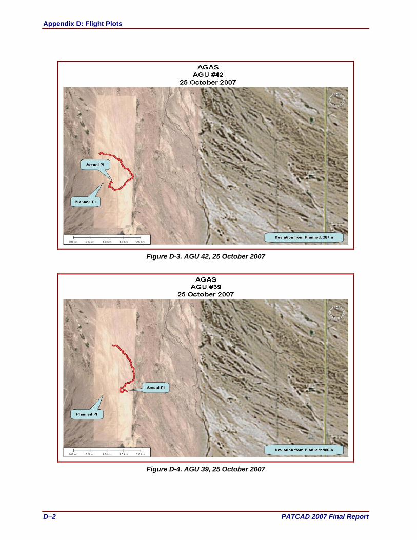
Appendix D: Flight Plots
D–2 PATCAD 2007 Final Report
Figure D-3. AGU 42, 25 October 2007
Figure D-4. AGU 39, 25 October 2007

Appendix D: Flight Plots
PATCAD 2007 Final Report D–3
Figure D-5. AGU 9, 25 October 2007
Figure D-6. AGU 40, 25 October 2007

Appendix D: Flight Plots
D–4 PATCAD 2007 Final Report
This page is intentionally blank.

Appendix D: Flight Plots
PATCAD 2007 Final Report D–5
Onyx 300
Figure D-7. Unit 74, 24 October 2007
Figure D-8. Unit 90, 24 October 2007

Appendix D: Flight Plots
D–6 PATCAD 2007 Final Report
Figure D-9. Unit 122, 24 October 2007
Figure D-10. Unit 74, 25 October 2007
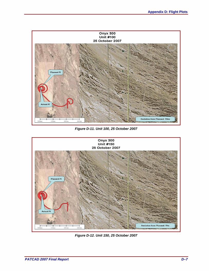
Appendix D: Flight Plots
PATCAD 2007 Final Report D–7
Figure D-11. Unit 100, 25 October 2007
Figure D-12. Unit 150, 25 October 2007

Appendix D: Flight Plots
D–8 PATCAD 2007 Final Report
This page is intentionally blank.

Appendix D: Flight Plots
PATCAD 2007 Final Report D–9
Panther 500
Figure D-13. AGU 007, 23 October 2007
Figure D-14. AGU 006, 24 October 2007
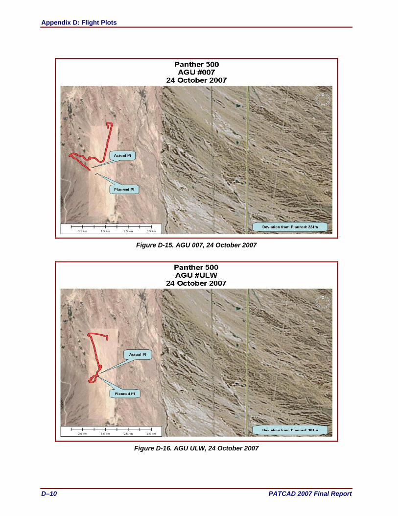
Appendix D: Flight Plots
D–10 PATCAD 2007 Final Report
Figure D-15. AGU 007, 24 October 2007
Figure D-16. AGU ULW, 24 October 2007

Appendix D: Flight Plots
PATCAD 2007 Final Report D–11
Figure D-17. AGU 006, 25 October 2007
Figure D-18. AGU 7500, 25 October 2007

Appendix D: Flight Plots
D–12 PATCAD 2007 Final Report
This page is intentionally blank.

Appendix D: Flight Plots
PATCAD 2007 Final Report D–13
10K SCREAMER
Figure D-19. AGU 1013, 24 October 2007
Figure D-20. AGU 1014, 25 October 2007

Appendix D: Flight Plots
D–14 PATCAD 2007 Final Report
Figure D-21. AGU 1029, 24 October 2007
Figure D-22. AGU 1036, 25 October 2007

Appendix D: Flight Plots
PATCAD 2007 Final Report D–15
Figure D-23. AGU 1038, 24 October 2007
Figure. D-24. AGU 1122, 25 October 2007

Appendix D: Flight Plots
D–16 PATCAD 2007 Final Report
Figure D-25. AGU 1124, 25 October 2007
Figure D-26. AGU 1130, 24 October 2007
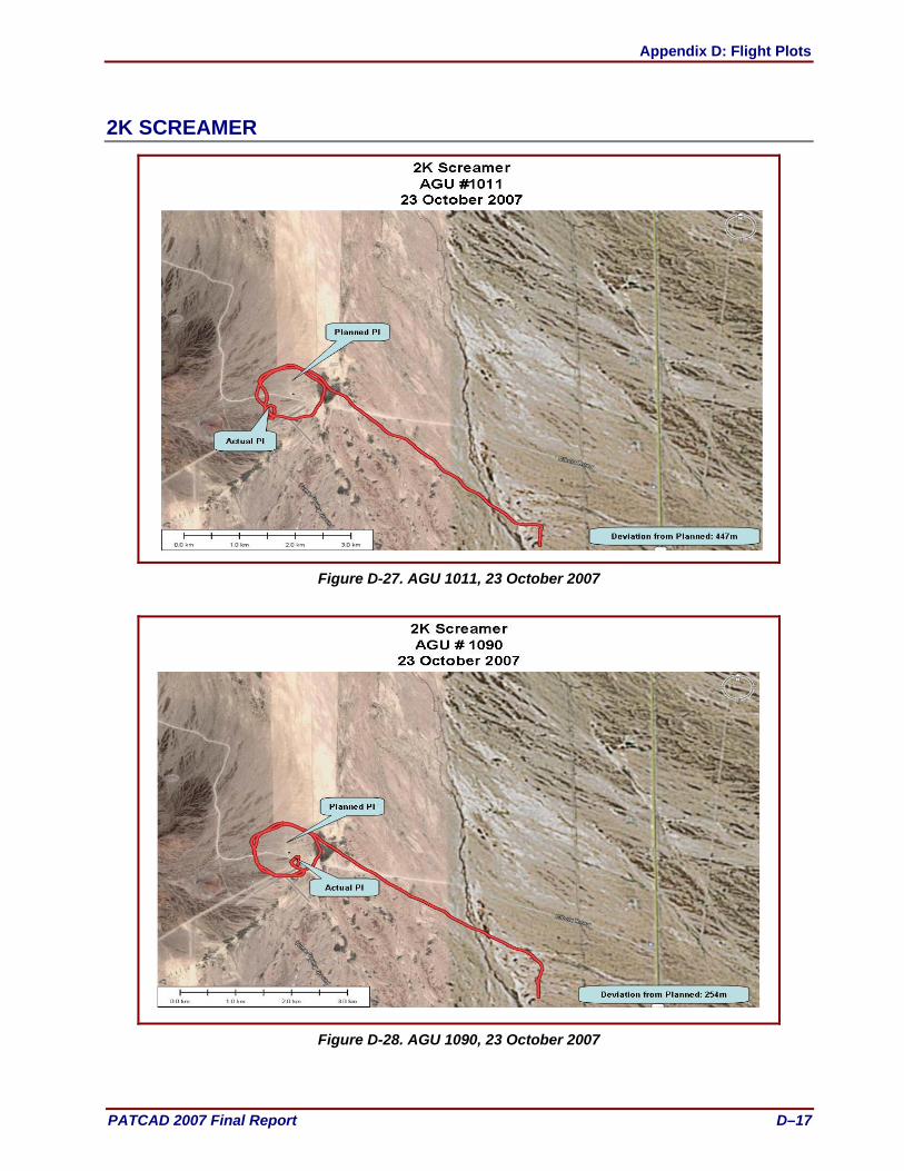
Appendix D: Flight Plots
PATCAD 2007 Final Report D–17
2K SCREAMER
Figure D-27. AGU 1011, 23 October 2007
Figure D-28. AGU 1090, 23 October 2007

Appendix D: Flight Plots
D–18 PATCAD 2007 Final Report
Figure D-29. AGU 1010, 25 October 2007
Figure D-30. AGU 1011, 25 October 2007

Appendix D: Flight Plots
PATCAD 2007 Final Report D–19
Figure D-31. AGU 1031, 25 October 2007
Figure D-32. AGU 1034, 25 October 2007
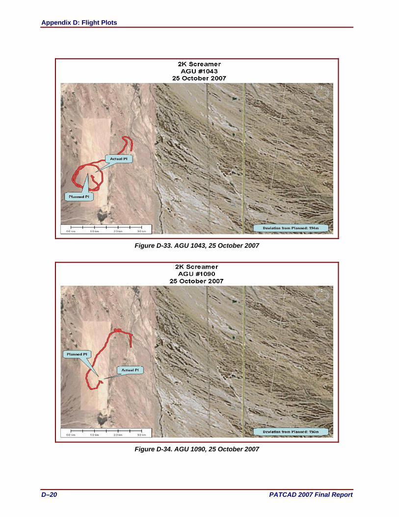
Appendix D: Flight Plots
D–20 PATCAD 2007 Final Report
Figure D-33. AGU 1043, 25 October 2007
Figure D-34. AGU 1090, 25 October 2007

Appendix D: Flight Plots
PATCAD 2007 Final Report D–21
Figure D-35. AGU 1110, 25 October 2007
Figure D-36. AGU 1131, 25 October 2007

Appendix D: Flight Plots
D–22 PATCAD 2007 Final Report
This page is intentionally blank.

Appendix D: Flight Plots
PATCAD 2007 Final Report D–23
Sherpa 1200/2200
Figure D-37. AGU 1392, 24 October 2007
Figure D-38. AGU 1388, 24 October 2007

Appendix D: Flight Plots
D–24 PATCAD 2007 Final Report
Figure D-39. AGU 2468, 24 October 2007
Figure D-40. AGU 2296, 24 October 2007

Appendix D: Flight Plots
PATCAD 2007 Final Report D–25
Figure D-41. AGU 005, 25 October 2007
Figure D-42. AGU 006, 25 October 2007

Appendix D: Flight Plots
D–26 PATCAD 2007 Final Report
Figure D-43. AGU 1427, 25 October 2007
Figure D-44. AGU 1701, 25 October 2007
