replacing firewall (brocade 5600 vrouter) with firewall (vsrx) firewall(brocade5600 vrouter)with...
TRANSCRIPT

Copyright © NTT Communications Corporation. All right reserved.Copyright © NTT Communications Corporation. All right reserved.
First Edition
Replacing Firewall (Brocade 5600 vRouter) with Firewall (vSRX)
Copyright © NTT Communications Corporation. All right reserved. 2
Update History
Date Update edition number
2018/10/24 first edition 1
Copyright © NTT Communications Corporation. All right reserved. 2
Copyright © NTT Communications Corporation. All right reserved. 3
Prerequisites
Copyright © NTT Communications Corporation. All right reserved. 3

Copyright © NTT Communications Corporation. All right reserved. 4
Prerequisites
Copyright © NTT Communications Corporation. All right reserved. 4
*How to replace Firewall (Brocade 5600 vRouter) (vFW) with Firewall (vSRX)
*There is no change in the setting of the Internet-GW, Load balancer, or web server (Routing changes, etc.).
*Load balancer is two-arm model. For one-arm configuration, please replace the terms in accordance with your environment.
*Move the network used by the vFW to vSRX.=>Communication is interrupted from disconnecting the network used by the vFW to the transfer to the vSRX.
*Please refer to the link below for basic vSRX configuration.https://ecl.ntt.com/en/documents/tutorials/rsts/vSRX/basic/basic.html
*Please configure the routing settings according to your configuration.
*When creating vSRX, the interface (Ge-0/0/0.0) is configured in the Trust zone.=>After creation, please change each interface according to your environment.
*Both vFW and vSRX use stateful inspection.=>If you use stateless firewall, please replace it according to your environment.
*Perform the migration after a pre-test.
Copyright © NTT Communications Corporation. All right reserved. 5
Configuration and Migration Flow
Copyright © NTT Communications Corporation. All right reserved. 5
Copyright © NTT Communications Corporation. All right reserved. 6
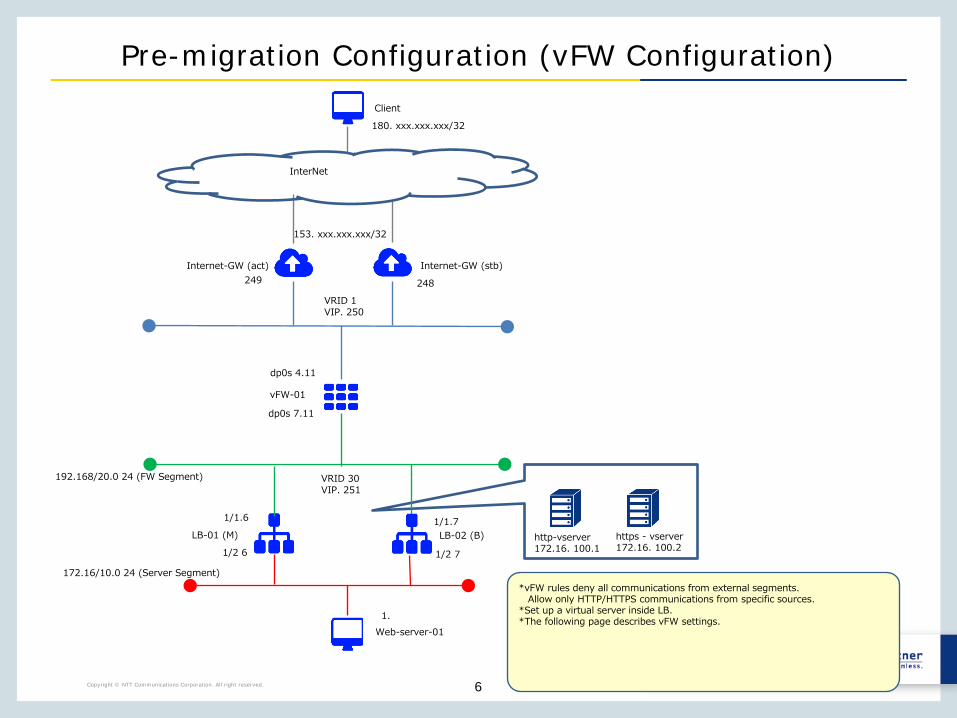
Pre-migration Configuration (vFW Configuration)
*vFW rules deny all communications from external segments.Allow only HTTP/HTTPS communications from specific sources.
*Set up a virtual server inside LB.*The following page describes vFW settings.
192.168/20.0 24 (FW Segment)
172.16/10.0 24 (Server Segment)
LB-01 (M)
Web-server-011.
1/1.6
http-vserver172.16. 100.1
https - vserver172.16. 100.2
vFW-01
dp0s 7.11
dp0s 4.11
LB-02 (B)1/1.7
1/2 6 1/2 7
VRID 30VIP. 251
153. xxx.xxx.xxx/32
Internet-GW (act)
InterNet
180. xxx.xxx.xxx/32
Client
Internet-GW (stb)
VRID 1VIP. 250
249 248

Copyright © NTT Communications Corporation. All right reserved. 7
Pre-migration configuration (vFW Configuration) settings
Configuring vFW-01 Firewall Filterset security firewall name From-Internet default-action 'drop'set security firewall name From-Internet rule 10 action 'accept'set security firewall name From-Internet rule 10 protocol 'tcp'set security firewall name From-Internet rule 10 source address '180. xxx.xxx.xxx/32'Set security firewall name From-Internet rule 10 destination port ’ 80 ’Set security firewall name From-Internet rule 10 state 'enable'Set security firewall name From-Internet rule 20 action 'accept'Set security firewall name From-Internet rule 20 protocol 'tcp'Set security firewall name From-Internet rule 20 source address '180. xxx.xxx.xxx/32'set security firewall name From-Internet rule 20 destination port '443'set security firewall name From-Internet rule 20 state 'enable'set security firewall name From-Internet rule 30 action 'accept'set security firewall name From-Internet rule 30 protocol 'vrrp'set security firewall name From-Internet rule 30 state 'enable'set interface dataplane dp0s4 firewall in 'From-Internet'
Copyright © NTT Communications Corporation. All right reserved. 8
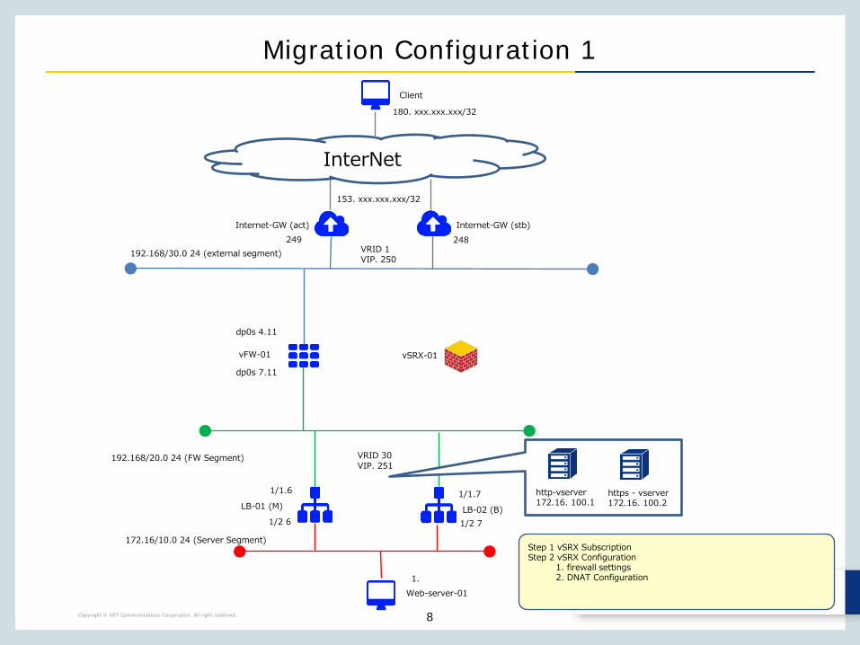
Migration Configuration 1
Step 1 vSRX SubscriptionStep 2 vSRX Configuration
1. firewall settings2. DNAT Configuration
192.168/20.0 24 (FW Segment)
vFW-01
dp0s 7.11
dp0s 4.11
vSRX-01
172.16/10.0 24 (Server Segment)
LB-01 (M)
Web-server-011.
1/1.6
LB-02 (B)
1/1.7
1/2 6 1/2 7
VRID 30VIP. 251
http-vserver172.16. 100.1
https - vserver172.16. 100.2
153. xxx.xxx.xxx/32
192.168/30.0 24 (external segment)
InterNet
180. xxx.xxx.xxx/32
Client
Internet-GW (act) Internet-GW (stb)249 248
VRID 1VIP. 250

Copyright © NTT Communications Corporation. All right reserved. 9
Migration Configuration 2
192.168/20.0 24 (FW Segment)
vSRX-01
172.16/10.0 24 (Server Segment)
LB-01 (M)
Web-server-011.
1/1.6
LB-02 (B)
1/1.7
1/2 6 1/2 7
VRID 30VIP. 251
http-vserver172.16. 100.1
https - vserver172.16. 100.2
Step 3 vFW Settings1. Disconnect IF (communication interruption)
vFW-01
Disconnection time: approximately 50 minutes (measured value)
153. xxx.xxx.xxx/32
192.168/30.0 24 (external segment)
InterNet
180. xxx.xxx.xxx/32
Client
Internet-GW (act) Internet-GW (stb)249 248
VRID 1VIP. 250
Copyright © NTT Communications Corporation. All right reserved. 10
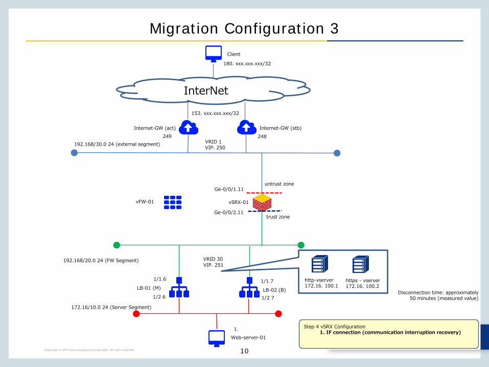
Migration Configuration 3
192.168/20.0 24 (FW Segment)
vSRX-01
172.16/10.0 24 (Server Segment)
LB-01 (M)
Web-server-011.
1/1.6
LB-02 (B)
1/1.7
1/2 6 1/2 7
VRID 30VIP. 251
http-vserver172.16. 100.1
https - vserver172.16. 100.2
vFW-01
Step 4 vSRX Configuration1. IF connection (communication interruption recovery)
Ge-0/0/1.11
Ge-0/0/2.11trust zone
untrust zone
Disconnection time: approximately 50 minutes (measured value)
153. xxx.xxx.xxx/32
192.168/30.0 24 (external segment)
InterNet
180. xxx.xxx.xxx/32
Client
Internet-GW (act) Internet-GW (stb)249 248
VRID 1VIP. 250
Copyright © NTT Communications Corporation. All right reserved. 11
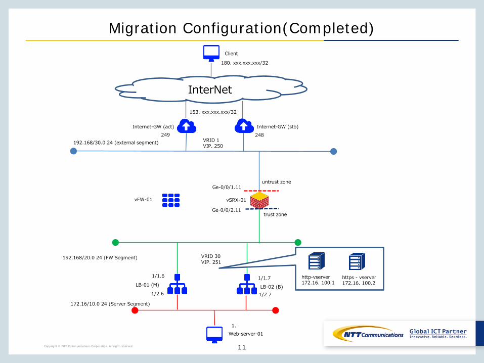
Migration Configuration(Completed)
192.168/20.0 24 (FW Segment)
vSRX-01
172.16/10.0 24 (Server Segment)
LB-01 (M)
Web-server-011.
1/1.6
LB-02 (B)
1/1.7
1/2 6 1/2 7
VRID 30VIP. 251
http-vserver172.16. 100.1
https - vserver172.16. 100.2
vFW-01
Ge-0/0/1.11
Ge-0/0/2.11trust zone
untrust zone
153. xxx.xxx.xxx/32
192.168/30.0 24 (external segment)
InterNet
180. xxx.xxx.xxx/32
Client
Internet-GW (act) Internet-GW (stb)249 248
VRID 1VIP. 250
Copyright © NTT Communications Corporation. All right reserved. 12
Step 1 vSRX Subscription
Copyright © NTT Communications Corporation. All right reserved. 12

Copyright © NTT Communications Corporation. All right reserved. 13Copyright © NTT Communications Corporation. All right reserved. 13
Please refer to the link below to apply for vSRX.https://ecl.ntt.com/en/documents/tutorials/rsts/vSRX/instance/create.html
After logging in to the control panel screen, click Cloud Computing.Click "NETWORK", "firewall", and "vSRX"
Step 1 vSRX Subscription
Copyright © NTT Communications Corporation. All right reserved. 14Copyright © NTT Communications Corporation. All right reserved. 14
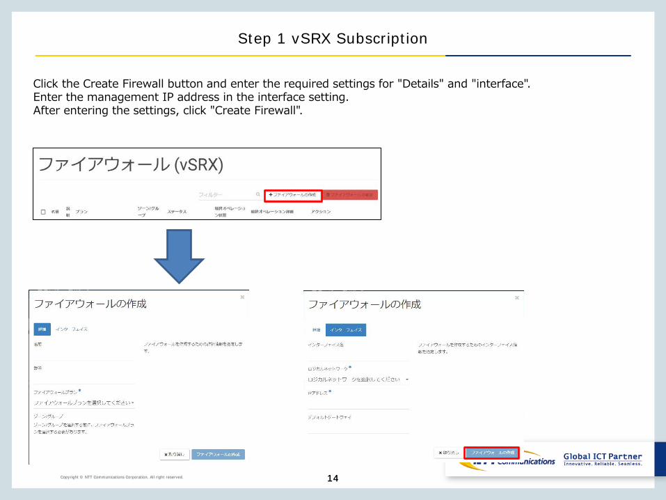
Click the Create Firewall button and enter the required settings for "Details" and "interface".Enter the management IP address in the interface setting.After entering the settings, click "Create Firewall".
Step 1 vSRX Subscription
Copyright © NTT Communications Corporation. All right reserved. 15
Step 2 -1 vSRX Configuration(firewall settings)
Copyright © NTT Communications Corporation. All right reserved. 15
Copyright © NTT Communications Corporation. All right reserved. 16Copyright © NTT Communications Corporation. All right reserved. 16
See below for zone based firewall settings.https://ecl.ntt.com/en/documents/tutorials/rsts/vSRX/fwfunction/zonebase/vsrx_zonebase.html
Create an area in the firewall that is logically called the "zones" and make the interface belong to a zone.The policy required for incoming packets is set on a per-zone basis, allowing the same policy to be applied to interfaces belonging to the zone.
To set up a zone-based firewall, you need "Address Group Settings" and "Application Set Settings"
Step 2 -1 vSRX Configuration(firewall settings)
Copyright © NTT Communications Corporation. All right reserved. 17
Step 2 -1 vSRX Configuration(firewall settings)
Copyright © NTT Communications Corporation. All right reserved. 17
Please set up the address group referring to the following URL.https://ecl.ntt.com/en/documents/tutorials/rsts/vSRX/fwfunction/zonebase/vsrx_address-set.html
When you configure packet filtering, you can set rules based on IP addresses, and you can assign simple names to IP addresses to set packet filtering conditions.If you want to group multiple IP addresses, create an address book for each IP address and create an address set containing multiple address books.
For reference, the vSRX-01 configuration values are:
user @ vSRX-01 # set security address-book global address CLIENT _ 01 180. xxx.xxx.xxx/32user @ vSRX-01 # set security address-book global address-set CLIENT _ GROUP address CLIENT _ 01user @ vSRX-01 # commit
Copyright © NTT Communications Corporation. All right reserved. 18
Step 2 -1 vSRX Configuration(firewall settings)
Copyright © NTT Communications Corporation. All right reserved. 18
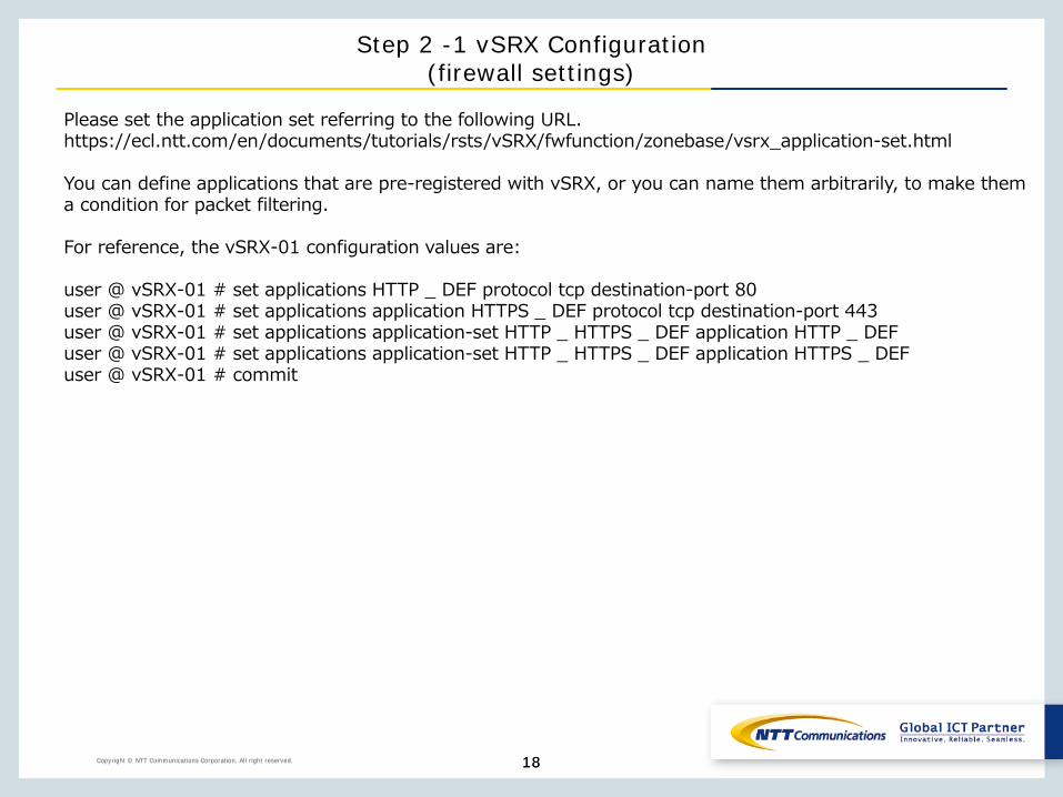
Please set the application set referring to the following URL.https://ecl.ntt.com/en/documents/tutorials/rsts/vSRX/fwfunction/zonebase/vsrx_application-set.html
You can define applications that are pre-registered with vSRX, or you can name them arbitrarily, to make them a condition for packet filtering.
For reference, the vSRX-01 configuration values are:
user @ vSRX-01 # set applications HTTP _ DEF protocol tcp destination-port 80user @ vSRX-01 # set applications application HTTPS _ DEF protocol tcp destination-port 443user @ vSRX-01 # set applications application-set HTTP _ HTTPS _ DEF application HTTP _ DEFuser @ vSRX-01 # set applications application-set HTTP _ HTTPS _ DEF application HTTPS _ DEFuser @ vSRX-01 # commit
Copyright © NTT Communications Corporation. All right reserved. 19Copyright © NTT Communications Corporation. All right reserved.
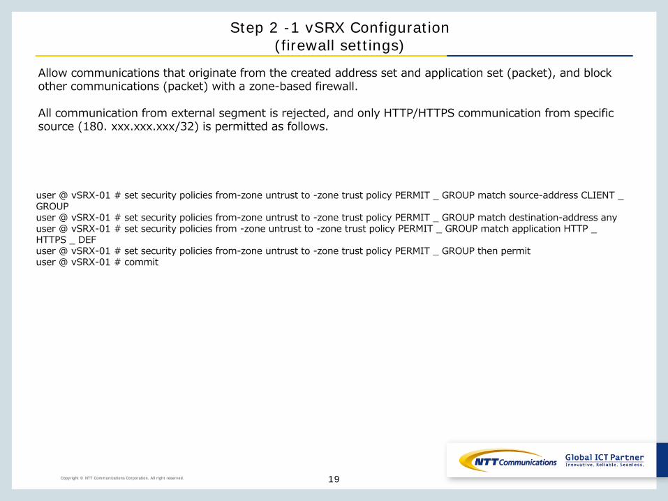
Allow communications that originate from the created address set and application set (packet), and block other communications (packet) with a zone-based firewall.
All communication from external segment is rejected, and only HTTP/HTTPS communication from specific source (180. xxx.xxx.xxx/32) is permitted as follows.
user @ vSRX-01 # set security policies from-zone untrust to -zone trust policy PERMIT _ GROUP match source-address CLIENT _ GROUPuser @ vSRX-01 # set security policies from-zone untrust to -zone trust policy PERMIT _ GROUP match destination-address anyuser @ vSRX-01 # set security policies from -zone untrust to -zone trust policy PERMIT _ GROUP match application HTTP _ HTTPS _ DEFuser @ vSRX-01 # set security policies from-zone untrust to -zone trust policy PERMIT _ GROUP then permituser @ vSRX-01 # commit
Step 2 -1 vSRX Configuration(firewall settings)
Copyright © NTT Communications Corporation. All right reserved. 20
Step 2 -2 vSRX Configuration(DNAT Configuration)
Copyright © NTT Communications Corporation. All right reserved. 20

Copyright © NTT Communications Corporation. All right reserved. 21
Step 2 -2 vSRX Configuration(DNAT Configuration)
Copyright © NTT Communications Corporation. All right reserved. 21
See below for Destination NAT configuration.https://ecl.ntt.com/en/documents/tutorials/rsts/vSRX/network/nat/nat.htmlAfter logging in to the CLI,Switch to shell command mode > operation mode > configuration mode.
Converts HTTP/HTTPS communications destined for 153. xxx.xxx.xxx/32 to the load balancer Virtual Server.
For reference, the vSRX-01 configuration values are listed on the next page.
Copyright © NTT Communications Corporation. All right reserved. 22
Step 2 -2 vSRX Configuration(DNAT Configuration)
Copyright © NTT Communications Corporation. All right reserved. 22
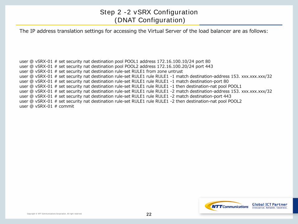
The IP address translation settings for accessing the Virtual Server of the load balancer are as follows:
user @ vSRX-01 # set security nat destination pool POOL1 address 172.16.100.10/24 port 80user @ vSRX-01 # set security nat destination pool POOL2 address 172.16.100.20/24 port 443user @ vSRX-01 # set security nat destination rule-set RULE1 from zone untrustuser @ vSRX-01 # set security nat destination rule-set RULE1 rule RULE1 -1 match destination-address 153. xxx.xxx.xxx/32user @ vSRX-01 # set security nat destination rule-set RULE1 rule RULE1 -1 match destination-port 80user @ vSRX-01 # set security nat destination rule-set RULE1 rule RULE1 -1 then destination-nat pool POOL1user @ vSRX-01 # set security nat destination rule-set RULE1 rule RULE1 -2 match destination-address 153. xxx.xxx.xxx/32user @ vSRX-01 # set security nat destination rule-set RULE1 rule RULE1 -2 match destination-port 443user @ vSRX-01 # set security nat destination rule-set RULE1 rule RULE1 -2 then destination-nat pool POOL2user @ vSRX-01 # commit
Copyright © NTT Communications Corporation. All right reserved. 23
Step 3 vFW Settings(Disconnect Interface)
Copyright © NTT Communications Corporation. All right reserved. 23

Copyright © NTT Communications Corporation. All right reserved. 24
Step 3 Configure vFW(Disconnect Interface)
Copyright © NTT Communications Corporation. All right reserved. 24
Please disconnect the logical network of firewall.After logging in to the control panel screen, click "NETWORK" and "Brocade 5600 vRouter" to select the firewall.
Copyright © NTT Communications Corporation. All right reserved. 25
Step 3 Configure vFW(Disconnect Interface)
Copyright © NTT Communications Corporation. All right reserved. 25
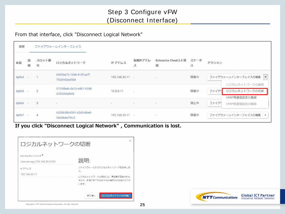
From that interface, click "Disconnect Logical Network"
If you click "Disconnect Logical Network" , Communication is lost.
Copyright © NTT Communications Corporation. All right reserved. 26
Step 4 vSRX Configuration(interface settings)
Copyright © NTT Communications Corporation. All right reserved. 26
Copyright © NTT Communications Corporation. All right reserved. 27Copyright © NTT Communications Corporation. All right reserved. 27
To configure IP address and enable communication for interface that is configured on the vSRX,you must configure the interface and IP address on the ECL 2.0 customer portal.
Set the IP address of vSRX to the IP address used in the vFW.
vSRX interface is not initially configured to belong to a zone, except for ge-0/0/0.To communicate, you must belong to one of the zones of the zone-based firewall.
To allow incoming communication to IP address of interface, you need to configure the host to allow that communication under host-inbound-traffic.
Step 4 vSRX Configuration(interface settings)

Copyright © NTT Communications Corporation. All right reserved. 28Copyright © NTT Communications Corporation. All right reserved. 28
Step 4 vSRX Configuration(interface settings)
Please refer to the link below to configure the vSRX interface on the ECL 2.0 customer portal.https://ecl.ntt.com/en/documents/tutorials/rsts/vSRX/instance/update.htmlAfter logging in to the control panel screen, click Cloud Computing.Click "NETWORK", "firewall", and "vSRX"
Copyright © NTT Communications Corporation. All right reserved. 29Copyright © NTT Communications Corporation. All right reserved. 29
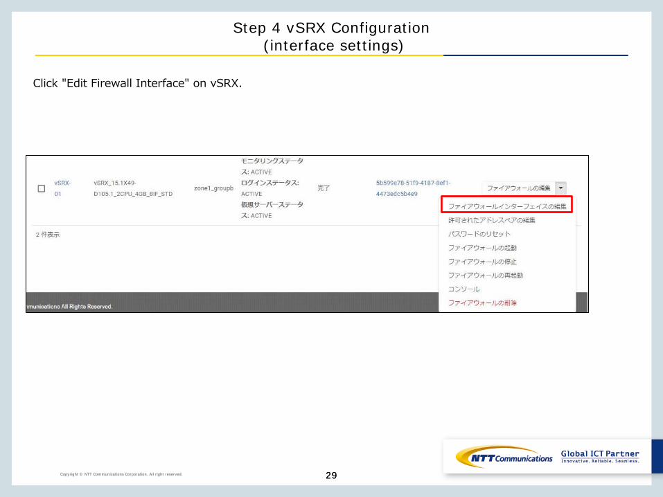
Click "Edit Firewall Interface" on vSRX.
Step 4 vSRX Configuration(interface settings)
Copyright © NTT Communications Corporation. All right reserved. 30Copyright © NTT Communications Corporation. All right reserved. 30
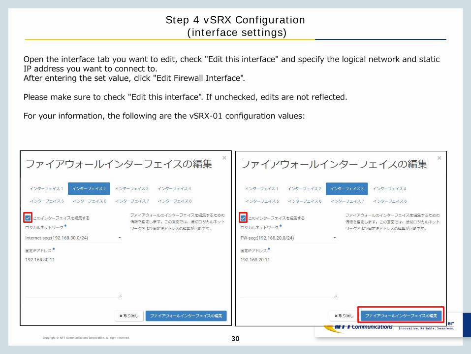
Open the interface tab you want to edit, check "Edit this interface" and specify the logical network and static IP address you want to connect to.After entering the set value, click "Edit Firewall Interface".
Please make sure to check "Edit this interface". If unchecked, edits are not reflected.
For your information, the following are the vSRX-01 configuration values:
Step 4 vSRX Configuration(interface settings)
Copyright © NTT Communications Corporation. All right reserved. 31Copyright © NTT Communications Corporation. All right reserved.
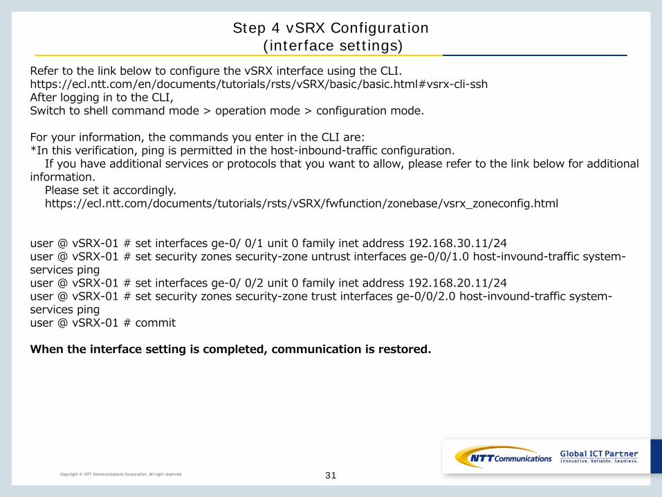
Refer to the link below to configure the vSRX interface using the CLI.https://ecl.ntt.com/en/documents/tutorials/rsts/vSRX/basic/basic.html#vsrx-cli-sshAfter logging in to the CLI,Switch to shell command mode > operation mode > configuration mode.
For your information, the commands you enter in the CLI are:*In this verification, ping is permitted in the host-inbound-traffic configuration.
If you have additional services or protocols that you want to allow, please refer to the link below for additional information.
Please set it accordingly.https://ecl.ntt.com/documents/tutorials/rsts/vSRX/fwfunction/zonebase/vsrx_zoneconfig.html
user @ vSRX-01 # set interfaces ge-0/ 0/1 unit 0 family inet address 192.168.30.11/24user @ vSRX-01 # set security zones security-zone untrust interfaces ge-0/0/1.0 host-invound-traffic system-services pinguser @ vSRX-01 # set interfaces ge-0/ 0/2 unit 0 family inet address 192.168.20.11/24user @ vSRX-01 # set security zones security-zone trust interfaces ge-0/0/2.0 host-invound-traffic system-services pinguser @ vSRX-01 # commit
When the interface setting is completed, communication is restored.
Step 4 vSRX Configuration(interface settings)