replaces iso/iec jtc 1/sc 25/wg 3...
TRANSCRIPT

ISO/IEC JTC 1/SC 25/WG 3 N 822 Date: 2007-03-06 Replaces ISO/IEC JTC 1/SC 25/WG 3 N/A
ISO/IEC JTC 1/SC 25/WG 3 Customer Premises Cabling Secretariat: Germany (DIN)
DOC TYPE: Liaison report TITLE: Liaison report from ISO/IEC/JTC 1/SC 25/WG 3 to
IEEE 802.3 on ISO/IEC 24764: Information technology - Generic cabling for Data Centre premises with copy to IEC SC 46C and IEC SC 86C
SOURCE: ISO/IEC JTC 1/SC 25/WG 3 (3Kona83A and 3Kona21)
PROJECT: 25.03.10: ISO/IEC 24764: IT - Generic cabling for Data Centre premises
STATUS: This liaison report has been developed at Kona, 2007-03-02.
ACTION ID: FYI DUE DATE: N/A REQUESTED: To IEEE 802.3, IEC SC 46C and IEC SC 86C for ACTION consideration. To WG 3 for information. MEDIUM: Def No of Pages: 38 (including cover) DISTRIBUTION: P-Members/Experts of JTC 1/SC 25/WG 3, see N 742 IEC Central Office, Mr Barta JTC 1 Secretariat, Mrs Rajchel DKE, Hr Wegmann JTC 1/SC 25 Chair Dr. Zeidler TC 1/SC 25 Sec Dr. von Pattay IEC TC 46 Chair, Sec Prof Halme/Mr Kincaid IEC SC46A Chair/Sec Prof. Halme, Mr Mund IEC SC 46C Chair/Sec, Brüggendieck/ Mr de Sainte Marie IEC TC 48 Chair/Sec/Liaison Weking/Toran/Joynes IEC TC 48B Chair/Sec Mr Joynes/Mr Toran IEC TC 86 Chair/Sec Rossi, Mr Matthews IEC/SC 86A Chair/Sec/Liaison Mr Zeidler/Mr Perrot/Swanson IEC TC 86B Chair/Sec/liaison Mr Lefevre/ Mr Sugita/Bolhaar IEC SB 4 Chair Mr Leppert CENELEC TC 215 Chair/Sec/Liais Roche/Wegmann/Gilmore IEEE 802 Chair/Liaison Mr. Nikolich/Mr. Flatman IEEE 802.3 Chair/Liaison Mr Grow/Mr Flatman
Secretary - ISO/IEC JTC 1 / SC 25/WG 3 - Dr.-Ing. Walter P. von Pattay ZVEI FV 7 & FV 8, Germany Tel.: +49/89/923 967 57, Tfx,: +49/89/923 967 59 (on request only) EM: [email protected] Home page SC 25: ”http:/www.iec.ch/sc25”

ISO/IEC JTC1/SC 25/WG 3 N 822 2007.03-06
Liaison report from ISO/IEC/JTC 1/SC 25/WG 3 to IEEE 802.3, IEC SC 46C and IEC SC 86C on
ISO/IEC 24764: Information technology - Generic cabling for Data Centre premises
To: IEEE 802.3 From: ISO/IEC JTC 1/SC 25/WG 3
42nd Meeting of WG 3 Keauhou near Kona, USA, 2007-02-26/03-02
Copy to: IEC SC 46C and IEC SC 86C Date: 2007-03-06
Please find attached the draft for the first committee draft of ISO/IEC 24764: IT - Generic cabling for Data Centre premises (3Kna21 future SC 25 N 1297). Table C.1 advises readers of the trade-off between channel length and connection insertion loss. WG 3 requests IEEE 802.3’s review and comments on this.
Concern has been expressed within WG 3 regarding the impact of connection losses on various link impairments for laser-based applications, such as modal noise, that may be dependent on the assumption of not exceeding the 1,5 dB insertion loss allocated by IEEE 802.3 standards. WG 3 seeks IEEE 802.3’s advice on the correct way to provide guidance on the distance/loss trade-off so as to ensure operational channels for IEEE 802.3 applications over cabling topologies containing many connections.
Observations from IEC SC 46C and IEC SC 86C are welcome
ISO/IEC JTC 1 / SC 25/WG 3n822.doc 1

ISO/IEC JTC1/SC 25/WG 3 N 822 2007.03-06
Information technology - Generic cabling for Data Centre premises
CONTENTS Foreword ............................................................................................................................. 5 Introduction.......................................................................................................................... 6 1 Scope ............................................................................................................................ 8 2 Normative references..................................................................................................... 8 3 Definitions and abbreviations ......................................................................................... 8
3.1 Definitions ............................................................................................................ 8 3.2 Abbreviations........................................................................................................ 9
4 Conformance ................................................................................................................. 9 5 Structure of the generic cabling system in data centres ................................................ 10
5.1 General .............................................................................................................. 10 5.2 Functional elements ............................................................................................ 10 5.3 General structure and hierarchy .......................................................................... 11 5.4 Cabling subsystems ............................................................................................ 12
5.4.1 Network access cabling subsystem.......................................................... 12 5.4.2 Main distribution cabling subsystem......................................................... 12 5.4.3 Zone distribution cabling subsystem ........................................................ 12 5.4.4 Design objectives .................................................................................... 12
5.5 Accommodation of functional elements................................................................ 12 5.6 Interfaces ........................................................................................................... 13
5.6.1 Equipment interfaces and test interfaces ................................................. 13 5.6.2 Channels and links .................................................................................. 13
5.7 Dimensioning and configuring ............................................................................. 14 5.7.1 Distributors ............................................................................................. 14 5.7.2 External network interface ....................................................................... 15 5.7.3 Cables .................................................................................................... 15 5.7.4 Equipment cords ..................................................................................... 16 5.7.5 Patch cords and jumpers ......................................................................... 16 5.7.6 Equipment outlets ................................................................................... 16 5.7.7 LDP ........................................................................................................ 16 5.7.8 Building entrance facilities ....................................................................... 16
5.8 Electromagnetic compatibility .............................................................................. 16 5.9 Earthing and equipotential bonding ..................................................................... 16
6 Channel performance in data centres ........................................................................... 17 6.1 General .............................................................................................................. 17 6.2 Environmental performance................................................................................. 17 6.3 Transmission performance .................................................................................. 17
6.3.1 General ................................................................................................... 17 6.3.2 Balanced cabling ..................................................................................... 18 6.3.3 Optical fibre cabling ................................................................................ 18
7 Reference implementations in data centres .................................................................. 18 7.1 General .............................................................................................................. 18 7.2 Balanced cabling ................................................................................................ 18
7.2.1 Assumptions ........................................................................................... 18 7.2.2 Zone distribution cabling ......................................................................... 18
ISO/IEC JTC 1 / SC 25/WG 3n822.doc 2

ISO/IEC JTC1/SC 25/WG 3 N 822 2007.03-06
7.2.3 Main distribution cabling .......................................................................... 21 7.2.4 Network access cabling ........................................................................... 22
7.3 Optical fibre cabling ............................................................................................ 25 7.3.1 Assumptions ........................................................................................... 25 7.3.2 Component choice................................................................................... 25 7.3.3 Optical fibre channel lengths ................................................................... 25
8 Cable requirements in data centres .............................................................................. 25 8.1 General .............................................................................................................. 25 8.2 Balanced cables ................................................................................................. 26 8.3 Optical fibre cables ............................................................................................. 26
9 Connecting hardware requirements in data centres ...................................................... 26 9.1 General requirements ......................................................................................... 26 9.2 Connecting hardware for balanced cabling .......................................................... 26
9.2.1 General requirements .............................................................................. 26 9.2.2 Mechanical and environmental performance ............................................ 26 9.2.3 Pin and pair assignments at the EO ......................................................... 27
9.3 Connecting hardware for optical fibre cabling ...................................................... 27 9.3.1 General requirements .............................................................................. 27 9.3.2 ENI requirements .................................................................................... 27 9.3.3 EO requirements ..................................................................................... 27
10 Requirements for cords and jumpers in data centres .................................................... 28 10.1 Jumpers ............................................................................................................. 28 10.2 Balanced cords ................................................................................................... 28 10.3 Optical fibre cords............................................................................................... 28
Annex A (normative) Link performance limits ..................................................................... 30 A.1 General ....................................................................................................................... 30 A.2 Balanced cabling ......................................................................................................... 30
A.2.1 General .............................................................................................................. 30 A.2.2 Balanced cabling ................................................................................................ 30
Annex B (Informative) Usage of high density connecting hardware.................................... 32 B.1 General ....................................................................................................................... 32 B.2 Channels and links ...................................................................................................... 32 B.3 Multi unit cable ............................................................................................................ 33 B.4 Multi unit connecting hardware ..................................................................................... 34 Annex C (normative) Channel insertion loss models for high bit rate, multimode, optical
fibre applications ......................................................................................................... 36 C.1 General ....................................................................................................................... 36 C.2 Channel attenuation allocation for connecting hardware ............................................... 36 Bibliography....................................................................................................................... 38
Figures
Figure 1 - Schematic relationship between the ISO/IEC 11801 series and other standards relevant for information technology cabling systems ............................................................. 7 Figure 2 - Structure of generic cabling ................................................................................ 11 Figure 3 - Hierarchical structure of generic cabling ............................................................. 12 Figure 4 - Example of accommodation of functional elements ............................................. 13 Figure 5 - Test and equipment interfaces............................................................................ 14
ISO/IEC JTC 1 / SC 25/WG 3n822.doc 3

ISO/IEC JTC1/SC 25/WG 3 N 822 2007.03-06
Figure 6 - Connection of functional elements providing redundancy .................................... 15 Figure 7 - The External Network Interface .......................................................................... 16 Figure 8 - Transmission performance of a channel.............................................................. 17 Figure 9 - Example of a system showing the location of cabling interfaces .......................... 17 Figure 10 - Zone distribution cabling models....................................................................... 20 Figure 11 – Main distribution cabling models ...................................................................... 21 Figure 12 - Network access cabling model.......................................................................... 23 Figure 13 - Pin grouping and pair assignments at the EO (front view of connector) ............. 28 Figure A. 1 - Link options ................................................................................................... 30
Tables
Table 1 - Zone distribution channel equations..................................................................... 19 Table 2 - Main distribution channel equations ..................................................................... 22 Table 3 - Network access cabling channel equations .......................................................... 24 Table 4 - Connecting hardware of the type used at the ENI ................................................. 26 Table 5 - Connecting hardware of the type used at the EO.................................................. 26 Table C. 1 – Maximum channel attenuation allocated to connecting hardware ..................... 37
ISO/IEC JTC 1 / SC 25/WG 3n822.doc 4

ISO/IEC JTC1/SC 25/WG 3 N 822 2007.03-06
INFORMATION TECHNOLOGY – GENERIC CABLING FOR DATA CENTRE PREMISES
Foreword
ISO (the International Organization for Standardization) and IEC (the International Electrotechnical Commission) form the specialised system for worldwide standardization. National bodies that are members of ISO or IEC participate in the development of International Standards through technical committees established by the respective organization to deal with particular fields of technical activity. ISO and IEC technical committees collaborate in fields of mutual interest. Other international organizations, governmental and non-governmental, in liaison with ISO and IEC, also take part in the work. In the field of information technology, ISO and IEC have established a joint technical committee, ISO/IEC JTC 1. Draft International Standards adopted by the joint technical committee are circulated to national bodies for voting. Publication as an International Standard requires approval by at least 75 % of the national bodies casting a vote. International Standard ISO/IEC 24XXX was prepared by the Joint Technical Committee ISO/IEC JTC 1/SC 25, Interconnection of Information Technology Equipment. This International Standard has taken into account requirements specified in application standards listed in Annex F of ISO/IEC 11801:200X. It refers to International Standards for components and test methods whenever appropriate International Standards are available.
ISO/IEC JTC 1 / SC 25/WG 3n822.doc 5

ISO/IEC JTC1/SC 25/WG 3 N 822 2007.03-06
•
•
•
•
Introduction
Within premises, the importance of the information technology cabling infrastructure is similar to that of other fundamental building utilities such as heating, lighting and mains power. As with other utilities, interruptions to service can have serious impact. Poor quality of service due to lack of design foresight, use of inappropriate components, incorrect installation, poor administration or inadequate support can threaten an organisation's effectiveness. Cabling within data centres comprises both application-specific and multipurpose networks that are mission-critical to the enterprise. Generic cabling designs in accordance with ISO/IEC 11801 have supported the development of high data rate applications based upon a defined cabling model. This International standard recognizes the benefit of generic cabling to provision multiple services and to connect large quantities of equipment within the limited space of data centre premises, and is to be used in conjunction with ISO/IEC 11801:200X. This International Standard provides: a) users with an application independent generic cabling system and an open market for cabling
components; b) requirements for infrastructures that support critical applications within data centres ; c) a flexible cabling scheme such that modifications are both easy and economical; d) a scaleable structure to support expansion with minimum operational disruption; e) building professionals (for example, architects) with guidance allowing the accommodation of
cabling before specific requirements are known; i.e. in the initial planning either for construction or refurbishment;
f) industry and standardisation bodies with a cabling system which supports current products and provides a basis for future product development and applications standardisation.
This International Standard specifies multi-vendor cabling, and is related to: the associated standard covering general requirements for generic cabling within premises (ISO/IEC 11801:200X);
standards for cabling components developed by Technical Committees of IEC;
standards for the quality assurance and installation of information technology cabling (series ISO/IEC TR 14763) and testing of installed cabling (IEC 61935-1 and ISO/IEC 14763-3);
applications developed by the technical committees of IEC, subcommittees of ISO/IEC JTC 1 and study groups of ITU-T 1).
It is anticipated that the generic cabling system meeting the requirements of this International Standard will have a life expectancy up to ten years.
1) International Telecommunication Union - Telecommunications Standardization Sector.
ISO/IEC JTC 1 / SC 25/WG 3n822.doc 6

ISO/IEC JTC1/SC 25/WG 3 N 822 2007.03-06
Figure 1 show the schematic and contextual relationships between the standards produced by ISO/IEC JTC1 SC25 for information technology cabling, namely this and other generic cabling design standards (ISO/IEC 11801), cabling installation standards (ISO/IEC 14763-1 and ISO/IEC 14763-2), testing of installed cabling (IEC 61935-1 and ISO/IEC 14763-3) and equipotential bonding requirements (IEC 61000-5-2).
ISO/IEC 11801: Information technology: Generic cabling for customer premises
ISO/IEC 24XXX: Information technology: Generic cabling - Data Centre
ISO/IEC TR 14763-2: Information technology. Implementation and operation of customer premises cabling: Planning and installation
ISO/IEC 18010: Information technology. Pathways and spaces for customer premises cabling
ISO/IEC TR 14763-1: Information technology. Implementation and operation of customer premises cabling: Administration
IEC 61000-5-2: Electromagnetic compatibility: Earthing and cabling
IEC 61935-1: Generic cabling systemsSpecifications for the testing of balanced communication cabling
IEC 60364-1: Electrical installations of buildings: Fundamental principles, assessment of general characteristics, definitions
ISO/IEC 14763-3: Information technology: Testing of optical fibre cabling
Figure 1 - Schematic relationship between the ISO/IEC 11801 series and other standards relevant for information technology cabling systems
ISO/IEC JTC 1 / SC 25/WG 3n822.doc 7

ISO/IEC JTC1/SC 25/WG 3 N 822 2007.03-06
1 Scope
This International Standard specifies generic cabling that supports a wide range of communications services for use within a data centre. It covers balanced cabling and optical fibre cabling. This International Standard is based upon and references the requirements of ISO/IEC 11801. This International Standard contains additional requirements that are appropriate to data centres in which the maximum distance over which communications services have to be distributed is 2 000 m. The principles of this International Standard may also be applied to installations that do not fall within this range. In addition to the requirements of ISO/IEC 11801, this International Standard specifies: a) a modified structure and configuration for generic cabling within data centres used to support
existing and emerging applications; b) implementation options to reflect the quantity of connections required in data centre
infrastructures; c) Requirements that reflect the range of operating environments within data centres. Safety (electrical safety and protection, fire, optical power etc.) and electromagnetic compatibility (EMC) requirements are outside the scope of this International Standard and are covered by other standards and regulations. However, information given in this International Standard may be of assistance in meeting these standards and regulations.
2 Normative references
The following referenced documents are indispensable for the application of this document. For dated references, only the edition cited applies. For undated references, the latest edition of the referenced document (including any amendments) applies. ISO/IEC 14763-1, Information technology - Implementation and operation of customer premises cabling - Part 1: Administration ISO/IEC TR 14763-2, Information technology - Implementation and operation of customer premises cabling - Part 2: Planning and installation ISO/IEC 14763-3, Information technology - Implementation and operation of customer premises cabling - Part 3: Testing of optical fibre cabling ISO/IEC 11801:200X, Information technology – Generic cabling for customer premises IEC 61754-20, Fibre optic connector interfaces - Part 20: Type LC connector familyEN 61754-7, Fibre optic connector interfaces - Type MPO connector family (IEC 61754-7:2004)
3 Definitions and abbreviations
3.1 Definitions For the purposes of this International Standard the following definitions apply in addition to those of ISO/IEC 11801.
3.1.1 equipment outlet fixed connecting device where the zone distribution cabling terminates. The equipment outlet provides the interface to the equipment cabling
3.1.2 fixed zone distribution cable cable connecting the zone distributor to either the equipment outlet or the local distribution point (if present)
3.1.3 local distribution point connection point in the zone distribution cabling subsystem between a zone distributor and an equipment outlet
3.1.4 local distribution point cable cable connecting a local distribution point to an equipment outlet
ISO/IEC JTC 1 / SC 25/WG 3n822.doc 8

ISO/IEC JTC1/SC 25/WG 3 N 822 2007.03-06
3.1.5 local distribution point link transmission path between a local distribution point and the interface at the other end of the fixed zone distribution cable including the connecting hardware at each end
3.1.6 main distribution cable cable connecting the main distributor to the zone distributor
3.1.7 main distributor distributor used to make connections between the main distribution cabling subsystem, network access cabling subsystem and cabling subsystems specified in ISO/IEC 11801 and active equipment
3.1.8 network access cable cable connecting the external network interface to the main distributor or zone distributor
3.1.9 zone distribution cable cable connecting the zone distributor to the equipment outlet(s) or local distribution point(s)
3.1.10 zone distributor distributor used to make connections between the main distribution cabling subsystem, zone distribution cabling subsystem, network access cabling subsystem and cabling subsystems specified in ISO/IEC 11801 series and active equipment
3.2 Abbreviations For the purposes of this International Standard the following abbreviations apply in addition to those of ISO/IEC 11801. BEF Building Entrance Facility EE Expanded Equipment EI Equipment Interface ENI External Network Interface EO Equipment outlet EQP Transmission Equipment LDP Local distribution point MD Main distributor OE EQP Opto-electronic Equipment TI Test Interface ZD Zone distributor
4 Conformance
For a cabling system to conform to this International Standard: a) the structure and configuration shall conform to the requirements of Clause 5;
b) connecting hardware in the cabling structure shall conform to the requirements of Clause 9.
c) the performance of channels shall conform to the transmission performance and environmental requirements of Clause 6. This shall be achieved by one of the following:
ISO/IEC JTC 1 / SC 25/WG 3n822.doc 9

ISO/IEC JTC1/SC 25/WG 3 N 822 2007.03-06
⎯ a channel design and implementation ensuring that the prescribed channel performance Class is met;
⎯ attachment of appropriate components to a link design meeting the prescribed performance Class of Annex A. Channel performance shall be assured where a channel is created by adding more than one cord to either end of a link meeting the requirements of Annex A;
⎯ using the reference implementations of Clause 7 and compatible cabling components conforming to the requirements of Clauses 8, 9 and 10, based upon a statistical approach of performance modelling.
d) local regulations concerning safety shall be met.
Test methods to ensure conformance with the channel and link requirements of Clause 6 and Annex A respectively are specified in IEC 61935-1 for balanced cabling and ISO/IEC 14763-3 for optical cabling. The treatment of measured results that fail to meet the requirements of this Clause, or lie within the relevant measurement accuracy, shall be clearly documented within a quality plan as described in ISO/IEC TR 14763-2. Installation of cabling in accordance with this International standard shall be undertaken in accordance with the ISO/IEC TR 14763-2 series of standards. Administration of cabling in accordance with this International standard shall be undertaken in accordance with the ISO/IEC 14763-1. This standard does not specify which tests and sampling levels should be adopted. The test parameters to be measured and the sampling levels to be applied for a particular installation shall be defined in the installation specification and quality plans for that installation prepared in accordance with ISO/IEC TR 14763-2. Specifications marked "ffs" (for further study) in ISO/IEC 11801:200X are preliminary and are not required for conformance to this International Standard.
5 Structure of the generic cabling system in data centres
5.1 General This Clause identifies the functional elements of generic cabling, describes how they are connected together to form subsystems and identifies the interfaces at which application-specific components are connected. Channels, created by connecting application-specific cabling components to the generic cabling, are used to support applications. Applications listed in ISO/IEC 11801:200X, Annex F, are supported by connecting active equipment at the external network interfaces, equipment outlets and the distributors. In general, all functional elements, subsystems and interfaces from the campus distributor to the floor distributor as described in ISO/IEC 11801 are applicable. The structured cabling system specified by this International Standard is intended to restrict the use of point-to-point cabling within data centres (except between equipment located in close proximity or between equipment that cannot communicate over the generic cabling system), which can be detrimental to the administration and operation of the data center.
5.2 Functional elements In addition to the distributors specified in ISO/IEC 11801 this standard specifies the following functional elements and interfaces of generic cabling: a) external network interface (ENI); b) network access cable; c) main distributor (MD); d) main distribution cable; e) zone distributor (ZD); f) zone distribution cable; g) local distribution point (LDP); h) local distribution point cable (LDP cable); i) equipment outlet (EO). Groups of these functional elements are connected together to form cabling subsystems.
ISO/IEC JTC 1 / SC 25/WG 3n822.doc 10

ISO/IEC JTC1/SC 25/WG 3 N 822 2007.03-06
5.3 General structure and hierarchy Generic cabling systems contain up to three cabling subsystems: network access cabling, main distribution cabling and zone distribution cabling. Where present within the premises, a distributor in accordance with ISO/IEC 11801 is connected to the generic cabling using the network access cabling. The cabling subsystems are connected together to create a generic cabling system with a structure as shown in Figure 2. The composition of the cabling subsystems is described in 5.4.1, 5.4.2 and 5.4.3. The functional elements of the cabling subsystems are interconnected to form a basic hierarchical topology as shown in Figure 3. Where the functions of distributors are combined (see 5.7.1) the intermediate cabling subsystem(s) are not required. Connections between cabling subsystems are either active, requiring application-specific equipment, or passive. Connection to application-specific equipment at an MD and ZD adopts an interconnect or a cross-connect approach (see ISO/IEC 11801). Connection to application-specific equipment at an ENI and EO adopts an interconnect approach (see ISO/IEC 11801). Passive connections between cabling subsystems adopt either a cross-connect approach, by way of either patch cords or jumpers, or an interconnect approach.
Networkaccess cabling
subsystem
Main distributioncabling
subsystem
Zone distributioncabling subsystem
Generic cabling system
Distributorin accordancewith ISO/IEC 11801
ENI LDPMD ZD EO
Equipmentcabling
EQP
Networkaccess cabling
subsystem
Main distributioncabling
subsystem
Zone distributioncabling subsystem
Generic cabling system
Distributorin accordancewith ISO/IEC 11801
ENI LDPMD ZD EO
Equipmentcabling
EQPEQPEQP
Figure 2 - Structure of generic cabling
Main distribution cabling subsystem
Network access cabling subsystem
Zone distributioncabling subsystem
optional cables
ZD
LDP LDP
ZD
LDP LDP
MD
ENI ENIDistributorin accordancewith ISO/IEC 11801
EO EO EO EO EO EO EO EO EO EO
Main distribution cabling subsystem
Network access cabling subsystem
Zone distributioncabling subsystem
optional cables
ZD
LDP LDP
ZD
LDP LDP
MD
ENI ENIDistributorin accordancewith ISO/IEC 11801
EO EO EO EO EO EO EO EO EO EO
ISO/IEC JTC 1 / SC 25/WG 3n822.doc 11

ISO/IEC JTC1/SC 25/WG 3 N 822 2007.03-06
NOTE Network access cabling is also used to connect ENI to ZD.
Figure 3 - Hierarchical structure of generic cabling
5.4 Cabling subsystems
5.4.1 Network access cabling subsystem The network access cabling subsystem extends from an MD (or ZD) to the ENIs and/or other
distributors in accordance with ISO/IEC 11801 connected to it. The subsystem includes: a) the network access cables; b) the mechanical termination of the network access cables at the ENI; c) the mechanical termination of the network access cables at the MD, ZD or other distributors in
accordance with ISO/IEC 11801. Although equipment cords are used to connect the transmission equipment to the cabling subsystem, they are not considered part of the cabling subsystem because they are application-specific.
5.4.2 Main distribution cabling subsystem The main distribution cabling subsystem extends from an MD to the ZDs connected to it. The subsystem includes: a) the main distribution cables; b) the mechanical termination of the main distribution cables at the MD together with associated
patch cords and/or jumpers at the MD; c) the mechanical termination of the main distribution cables at the ZD. Although equipment cords are used to connect the transmission equipment to the cabling subsystem, they are not considered part of the cabling subsystem because they are application-specific.
5.4.3 Zone distribution cabling subsystem The zone distribution cabling subsystem extends from a ZD to the EOs connected to it. The subsystem includes: a) the zone distribution cables; b) the mechanical termination of the zone distribution cables at the EO and the ZD together with
associated patch cords and/or jumpers at the ZD; c) an LDP (optional); d) an LDP cable (optional) ; e) the EO. Although equipment cords are used to connect the transmission equipment to the cabling subsystem, they are not considered part of the cabling subsystem because they are application-specific. Zone distribution cables shall be continuous from the ZD to the EOs unless an LDP is installed (see 5.7.7).
5.4.4 Design objectives In order to provide longest operational life while minimising the disruption and cost associated with re-cabling, the fixed installed cabling should be designed to: a) support the broadest set of existing and emerging applications;
b) accommodate the anticipated growth in volume of supported applications throughout the predicted lifetime of the installation.
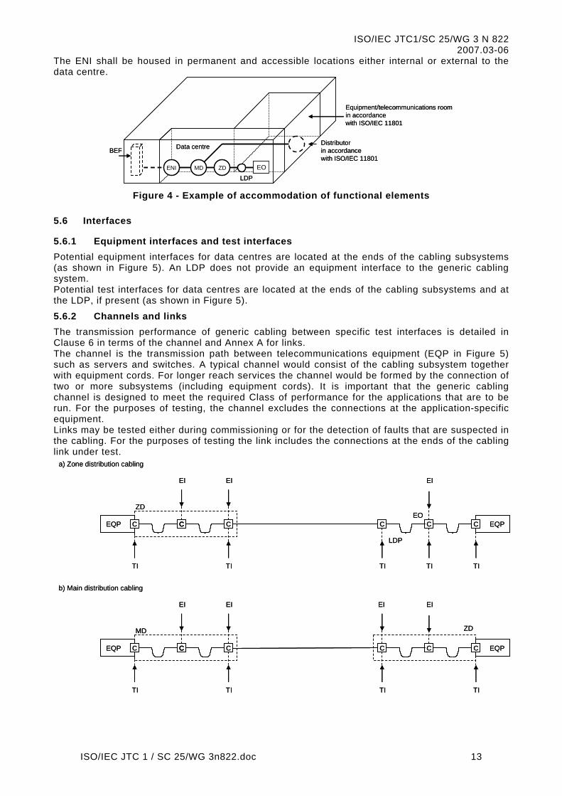
5.5 Accommodation of functional elements Figure 4 shows an example of how the functional elements are accommodated in a building (only a single floor of the building is shown for simplicity). The MD, ZD and LDP shall be housed in permanent and accessible locations within the data centre.
ISO/IEC JTC 1 / SC 25/WG 3n822.doc 12
ISO/IEC JTC1/SC 25/WG 3 N 822 2007.03-06
The ENI shall be housed in permanent and accessible locations either internal or external to the data centre.
ENI
BEF
MD ZD
Distributorin accordancewith ISO/IEC 11801
Equipment/telecommunications roomin accordancewith ISO/IEC 11801
Data centre
EOLDP
ENI
BEF
MD ZD
Distributorin accordancewith ISO/IEC 11801
Equipment/telecommunications roomin accordancewith ISO/IEC 11801
Data centre
EOLDP
Figure 4 - Example of accommodation of functional elements
5.6 Interfaces
5.6.1 Equipment interfaces and test interfaces Potential equipment interfaces for data centres are located at the ends of the cabling subsystems (as shown in Figure 5). An LDP does not provide an equipment interface to the generic cabling system. Potential test interfaces for data centres are located at the ends of the cabling subsystems and at the LDP, if present (as shown in Figure 5).
5.6.2 Channels and links The transmission performance of generic cabling between specific test interfaces is detailed in Clause 6 in terms of the channel and Annex A for links. The channel is the transmission path between telecommunications equipment (EQP in Figure 5) such as servers and switches. A typical channel would consist of the cabling subsystem together with equipment cords. For longer reach services the channel would be formed by the connection of two or more subsystems (including equipment cords). It is important that the generic cabling channel is designed to meet the required Class of performance for the applications that are to be run. For the purposes of testing, the channel excludes the connections at the application-specific equipment. Links may be tested either during commissioning or for the detection of faults that are suspected in the cabling. For the purposes of testing the link includes the connections at the ends of the cabling link under test.
a) Zone distribution cabling
b) Main distribution cabling
EQPC CEQP C C
TI TI
EI EI EI
TI
C
EI
MD ZD
TI
C
LDP
EOEQPC CEQP C C
TI TI
EI EI EI
TI
C
ZD
TI TI
C
a) Zone distribution cabling
b) Main distribution cabling
EQPC CEQP C C
TI TI
EI EI EI
TI
C
EI
MD ZD
TI
C
LDP
EOEQPC CEQP C C
TI TI
EI EI EI
TI
C
ZD
TI TI
C
ISO/IEC JTC 1 / SC 25/WG 3n822.doc 13

ISO/IEC JTC1/SC 25/WG 3 N 822 2007.03-06
c) Network access cabling from MD to distributor in accordance with ISO/IEC 11801
d) Network access cabling from MD to ENI
EQPC CEQP C C
TI TI
EI EI EI
TI
C
EI
MD
TI
C
Distributor in accordancewith ISO/IEC 11801
ENIEQPC CEQP C C
TI TI
EI EI EI
MD
TI TI
C
See NOTE
c) Network access cabling from MD to distributor in accordance with ISO/IEC 11801
d) Network access cabling from MD to ENI
EQPC CEQP C C
TI TI
EI EI EI
TI
C
EI
MD
TI
C
Distributor in accordancewith ISO/IEC 11801
ENIEQPC CEQP C C
TI TI
EI EI EI
MD
TI TI
C
See NOTE NOTE Where the EQP connected to the ENI lies outside the premises containing the data centres, the interconnecting cord will typically comprise a combination of fixed cabling and cords that are outside the scope of this standard. In such cases the connection to the EQP may not provide a TI.
Figure 5 - Test and equipment interfaces
5.7 Dimensioning and configuring
5.7.1 Distributors The number and type of subsystems that are included in a generic cabling implementation depends upon the layout and size of the data centre and upon the strategy of the user. The design of distributors should ensure that the lengths of patch cords, jumpers and equipment cords are minimised. The design lengths of the cords should be maintained during operation. Distributors should be located such that the resulting cable lengths are consistent with the channel performance requirements of Clause 6. Where the components of Clauses 8, 9 and 10 are used the distributors shall be located in accordance with the reference implementations of Clause 7. Where other components are used, distributors shall be located so that the desired performance Class of Clause 6 is delivered. The functions of multiple distributors may be combined into a single distributor. For example, a MD may serve the function of a ZD or ENI. However, every data centre must have at least one MD. In certain circumstances, for example for security or reliability reasons, redundancy may be built into a cabling design. Figure 6 shows one of many possible examples of the connection of functional elements within the structured framework to provide such protection against failure in one or more parts of the cabling infrastructure. This might form the basis for the design of generic cabling for a data centre providing some protection against such hazards as fire damage or the failure of the external network feeder cable.
ISO/IEC JTC 1 / SC 25/WG 3n822.doc 14

ISO/IEC JTC1/SC 25/WG 3 N 822 2007.03-06
Distributorin accordancewith ISO/IEC 11801
MDMD
ENI ENI
ZDZD
LDPLDP
EO EO EO EO EO EO EO EOEO EO EO EO
Distributorin accordancewith ISO/IEC 11801
MDMD
ENI ENI
ZDZD
LDPLDP
EO EO EO EO EO EO EO EOEO EO EO EO
Figure 6 - Connection of functional elements providing redundancy
Additionally, redundancy may be provided by utilizing multiple cables between distributors, with cables following different routes. NOTE: Connections between ZD and ZD are in addition to the connection between MD and ZD and not a replacement for the MD to ZD connection
5.7.2 External network interface The External Network Interface (ENI) is a termination of the network access cabling that allows connection of external services to the network access cabling as shown in Figure 7. NOTE: The multiple service providers should have diverse routes to each of the multiple ENIs.
The ENI interface presented shall be in accordance with Clause 9. Where the components of Clauses 8, 9 and 10 are used the ENIs shall be located in accordance with the reference implementations of Clause 7.
5.7.3 Cables Cable types used in the reference implementations of Clause 7 are given in Clause 8. Hardware for connecting cables shall only provide direct onward attachment for each conductor and shall not provide any contact between more than one incoming or outgoing conductor (e.g. bridge taps shall not be used).
ISO/IEC JTC 1 / SC 25/WG 3n822.doc 15

ISO/IEC JTC1/SC 25/WG 3 N 822 2007.03-06
EQP
Network access cabling
ENI
CENI
CENI
C
External service cabling(beyond the scope of this standard)
Interconnection
Crossconnection
Connection of networkAccess cabling to externalService cabling may includePassive or active equipment
EQP
Network access cabling
ENI
CENI
CENI
C
External service cabling(beyond the scope of this standard)
Interconnection
Crossconnection
Connection of networkAccess cabling to externalService cabling may includePassive or active equipment
Figure 7 - The External Network Interface
5.7.4 Equipment cords Equipment cords connect application-specific equipment to the generic cabling at the ENIs, EOs and distributors. Both are non-permanent and can be application-specific. The performance contribution of these cords shall be taken into account in the design of the channel. Clause 7 provides guidance on cord lengths for reference implementations of generic cabling.
5.7.5 Patch cords and jumpers Patch cords and jumpers are used within cross-connect implementations at distributors. The performance contribution of these cords shall be taken into account in the design of the channel. Clause 7 provides guidance on cord/jumper lengths for reference implementations of generic cabling.
5.7.6 Equipment outlets The design of generic cabling should provide for EOs to be installed with a high density and located in close proximity to the application-specific equipment to which they are to be connected. The number of cable elements presented at the EO is not restricted by this standard. A group of EOs can be served by multiple ZDs and/or LDPs. The EO interface presented shall be in accordance with Clause 9.
5.7.7 LDP The installation of an LDP in the zone distribution cabling between the ZD and the EO may be useful where frequent additions or movements of equipment are required. One LDP is permitted between a ZD and any EO. The LDP shall be an interconnect, not a crossconnect, because the LDP adds one connection per channel. There shall be no active equipment in the LDP area with the exception of DC powering equipment. Where an LDP is used, it shall have sufficient capacity to support the area of the data centre which it is designed to serve during its intended operational life. The area served may be defined in terms of number of frames/cabinets/closures to be supported and may include allowance for growth. It is possible to locate an LDP in ceiling voids and under floors provided that those locations meet the requirements of 5.5. For balanced cabling, the effect of multiple connections in close proximity on transmission performance should be taken into consideration when planning the cable lengths between the ZD and the LDP.
5.7.8 Building entrance facilities See ISO/IEC 11801.
5.8 Electromagnetic compatibility See ISO/IEC 11801.
5.9 Earthing and equipotential bonding See ISO/IEC 11801 and ISO/IEC TR 14763-2.
ISO/IEC JTC 1 / SC 25/WG 3n822.doc 16

ISO/IEC JTC1/SC 25/WG 3 N 822 2007.03-06
6 Channel performance in data centres
6.1 General This Clause specifies the minimum channel performance of balanced and optical fibre cabling in terms of the Classes as specified in Clause 6.3. The transmission performance of channels is specified at and between the connections to active equipment as shown in Figure 8. The channel comprises only passive sections of cable, connections, equipment cords, patch cords and jumpers. The transmission and environmental performance of the connections at the active equipment are the responsibility of the equipment supplier in support of the applications listed in ISO/IEC 11801:200X, Annex F.
EQPCEQP C C
Equipment cord
Patch cord/Jumper
Channel
CC
Patch cord/Jumper
Equipment cord
C
Figure 8 - Transmission performance of a channel
Application support depends on channel transmission performance only, which in turn depends on cable length, number of connections and performance of the components within the environments to which the channel is subjected. Channels are implemented using either:
•
•
•
•
network access cabling only;
main distribution cabling only;
zone distribution cabling only;
combinations of the above. Figure 9 shows an example of equipment at the MD connected to transmission equipment at the EO using two channels, an optical fibre channel and a balanced cabling channel. The optical fibre and balanced cabling channels are connected together using an optical fibre to balanced copper cable converter. There are four channel interfaces; one at each end of the balanced channel, and one at each end of the optical fibre channel.
EQPCEO
ZD
C
EQP
C
C
C
C
OE EQP
C
C
C C
C
MD
Balanced cabling channel
Optical fibre channel
C = optional connection
Figure 9 - Example of a system showing the location of cabling interfaces
6.2 Environmental performance See ISO/IEC 11801.
6.3 Transmission performance
6.3.1 General The channel transmission performance specifications are separated into Classes that allow for the transmission of the applications in ISO/IEC 11801:200X, Annex F.
ISO/IEC JTC 1 / SC 25/WG 3n822.doc 17

ISO/IEC JTC1/SC 25/WG 3 N 822 2007.03-06
•
•
•
The channel performance requirements described in this Clause shall be used for the design and may be used for verification of any implementation of this international standard, using the test methods defined, or referred to, by this Clause. In addition, these requirements can be used for application development and trouble shooting. The channel specifications in this Clause allow for the transmission of defined Classes of applications over distances other than those of Clause 7, and/or using media and components with different transmission performance than those of Clauses 8, 9 and 10. Consideration should be given to measuring performance at worst case temperatures, or calculating worst case performance based on measurements made at other temperatures. Link performance requirements are specified in Annex A.
6.3.2 Balanced cabling
The main distribution and zone distribution cabling shall be designed to provide a minimum of Class EA channel performance as specified in ISO/IEC 11801:200X.
NOTE: Higher density of connecting hardware in the transmission channel between two pieces of equipment allows for a lower class of service, see Annex B.
Editors Note: If ISO/IEC 11801 Amd. 1.1 is in a state to be referenced, no change is needed. In the case that this document are ready for publication before the amendment of 11801, a note is included to indicate that E is normative and conformance is possible, and EA is subject to matching conformance requirements of clause 1.2 and listing requirements.
6.3.3 Optical fibre cabling Cabling shall be designed using the optical fibre Categories referenced in Clause 8 to provide channel performance as required from Classes OF-300, OF-500 and OF-2000 as specified in ISO/IEC 11801. Where multimode optical fibre is used, the main distribution and zone distribution cabling shall be designed to provide a minimum of Class OF-300 channel performance using the Category OM2 or OM3 optical fibre cable products of Clause 8. The usage of OM3 optical fibre cable products are recommended.
7 Reference implementations in data centres
7.1 General This Clause describes implementations of generic cabling that utilise components referenced in Clauses 8, 9 and 10. These reference implementations meet the requirements of Clause 5 and, when installed in accordance with ISO/IEC TR 14763-2, comply with the channel performance requirements of Clause 6.
7.2 Balanced cabling
7.2.1 Assumptions Balanced cabling components referenced in Clauses 8, 9 and 10 are defined in terms of Category. In the reference implementations of this Clause, the components used in each cabling channel shall have the same nominal characteristic impedance in accordance with ISO/IEC 11801:200X, 7.2. The implementations are based on component performance at 20 °C. The effect of temperature on the performance of cables shall be taken into account as shown in Table 1, Table 2 and Table 3.
7.2.2 Zone distribution cabling
7.2.2.1 Component choice The selection of balanced cabling components will be determined by the Class of applications to be supported by the cabling. Refer to ISO/IEC 11801:200X, Annex F, for guidance. Using the models of 7.2.2.2:
Category 6A components provide Class E A balanced cabling performance;
Category 7 components provide Class F balanced cabling performance;
Category 7A components provide Class F A balanced cabling performance. Cables and connections of different Categories should not be mixed within a channel. If different Categories are mixed, the resultant cabling performance will be determined by the Category of the lowest performing component.
ISO/IEC JTC 1 / SC 25/WG 3n822.doc 18

ISO/IEC JTC1/SC 25/WG 3 N 822 2007.03-06
•
•
•
7.2.2.2 Dimensions Figure 10 shows the models used to correlate zone distribution cabling dimensions specified in this Clause with the channel specifications in Clause 5. Figure 10a shows a channel containing only an interconnect and an EO. Figure 10b contains an additional connection as a cross-connect. In both cases the fixed horizontal cable connects the ZD to the EO. The channel includes cords comprising patch and equipment cords. For the purposes of this subclause, jumpers used in place of patch cords are treated as cords. Figure 10c shows a channel containing an interconnect, an LDP and an EO. Figure 10d contains an additional connection as a cross-connect. In both cases the fixed zone distribution cable connects the ZD to the LDP. The channel includes cords comprising patch and equipment cords. For the purposes of this subclause, jumpers used in place of patch cords are treated as cords. In addition to the cords, the channels shown in Figure 10c and Figure 10d contain an LDP cable. The insertion loss specification for the LDP cable may differ from that of both the fixed zone distribution cable and the flexible cables. The channel of Figure 10d is recognized as the maximum implementation used to define the channel performance limits of Clause 6. In order to accommodate cables used for LDP cables, patch cords, jumpers and equipment cords with different insertion loss specifications, the length of the cables used within a channel shall be determined by the equations shown in Table 1. In Table 1 it is assumed that a) the flexible cable within these cords has a higher insertion loss specification than that used in
the fixed zone distribution cable (see Clause 10), b) the cables within these cords in the channel have a common insertion loss specification. The following general restrictions apply:
the physical length of the channel shall not exceed 100 m;
the physical length of the fixed zone distribution cable shall not exceed 90 m and may be less depending on the length of LDP cables and cords used and the number of connections;
when used, an LDP should be located at least 15 m from the ZD in order to reduce the effect of multiple connections in close proximity on NEXT and return loss.
The maximum length of the fixed zone distribution cable will depend on the total length of LDP cables and cords to be supported within a channel. During the operation of the installed cabling, a management system should be implemented to ensure that the cords and, where appropriate, the LDP cables used to create the channel conform with the design rules for the data centre.
Table 1 - Zone distribution channel equations
Model Figure Model equations
Class E A Class F and Class F A
Interconnect-EO 12a Z =107 - 3a - F×X Z =107 - 2a - F×X
Cross-connect-EO 12b Z =106 - 3a - F×X Z =106 - 3a - F×X
Interconnect-LDP-EO 12c Z =106 - 3a - F×X - L×Y Z =106 - 3a - F×X - L×Y
Cross-connect-LDP-EO 12d Z =105 - 3a - F×X - L×Y Z =105 - 3a - F×X - L×Y
Z maximum length of the fixed zone distribution cable (m)
F combined length of patch cords, jumpers and equipment cords (m)
L length of the LDP cable (m)
X ratio of flexible cable insertion loss (dB/m) to fixed zone distribution cable insertion loss (dB/m) - see Clause 10
Y ratio of LDP cable insertion loss (dB/m) to fixed zone distribution cable insertion loss (dB/m) - see Clause 10 a This length reduction is to provide an allocated margin to accommodate insertion loss deviation.
For operating temperatures above 20 °C, Z should be reduced by 0,2% per °C for screened cables and 0,4% per °C (20 oC to 40 oC) and 0,6% per °C (> 40 oC to 60 oC) for unscreened cables.
ISO/IEC JTC 1 / SC 25/WG 3n822.doc 19

ISO/IEC JTC1/SC 25/WG 3 N 822 2007.03-06
Equipment cord
Patch cord/Jumper
Fixed zone distribution
cable
EQPC CEQP C
Equipment cord
EOZD
Channel = 100 m max.
b) Cross-connect - EO model
C C
Equipment cord
Fixed zone distribution
cable
EQPCEQP C
Equipment cord
EOZD
Channel = 100 m max.
C C
a) Interconnect - EO model
Equipment cord
Patch cord/Jumper
EQPCEQP
Equipment cord
ZD
Channel = 100 m max.
d) Cross-connect - LDP - EO model
C C
Equipment cord
EQPCEQP C
Equipment cord
EOZD
Channel = 100 m max.
C C
c) Interconnect - LDP - EO model
Fixed zone distribution
cable
C
LDP cable
LDP
CCEO
Fixed zone distribution
cable
C
LDP cable
LDP
Figure 10 - Zone distribution cabling models
ISO/IEC JTC 1 / SC 25/WG 3n822.doc 20
ISO/IEC JTC1/SC 25/WG 3 N 822 2007.03-06
•
•
•
•
•
7.2.3 Main distribution cabling
7.2.3.1 Component choice The selection of balanced cabling components will be determined by the Class of applications to be supported by the cabling. Refer to ISO/IEC 11801:200X, Annex F, for guidance. Using the models of 7.2.3.2:
Category 6A components provide Class E A balanced cabling performance;
Category 7 components provide Class F balanced cabling performance;
Category 7 A components provide Class F A balanced cabling performance. Cables and connections of different Categories should not be mixed within a channel. If different Categories are mixed, the resultant cabling performance will be determined by the Category of the lowest performing component.
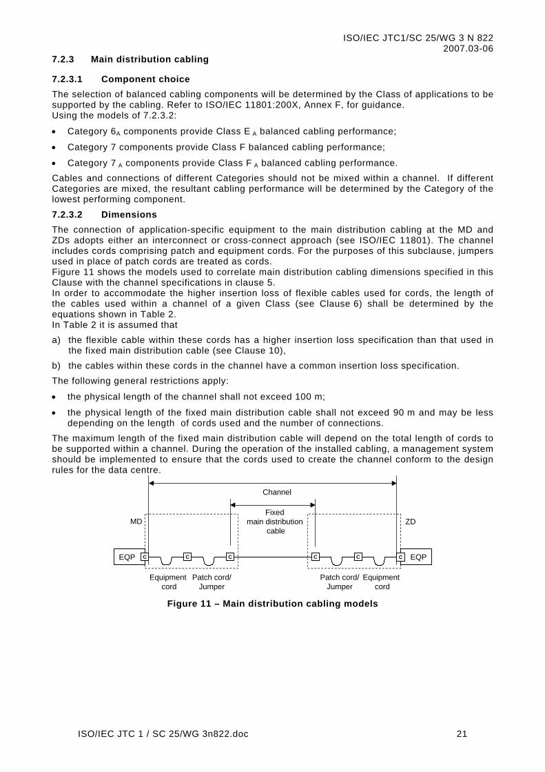
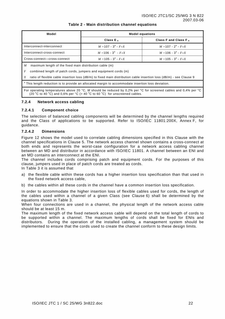
7.2.3.2 Dimensions The connection of application-specific equipment to the main distribution cabling at the MD and ZDs adopts either an interconnect or cross-connect approach (see ISO/IEC 11801). The channel includes cords comprising patch and equipment cords. For the purposes of this subclause, jumpers used in place of patch cords are treated as cords. Figure 11 shows the models used to correlate main distribution cabling dimensions specified in this Clause with the channel specifications in clause 5. In order to accommodate the higher insertion loss of flexible cables used for cords, the length of the cables used within a channel of a given Class (see Clause 6) shall be determined by the equations shown in Table 2. In Table 2 it is assumed that a) the flexible cable within these cords has a higher insertion loss specification than that used in
the fixed main distribution cable (see Clause 10), b) the cables within these cords in the channel have a common insertion loss specification. The following general restrictions apply:
the physical length of the channel shall not exceed 100 m;
the physical length of the fixed main distribution cable shall not exceed 90 m and may be less depending on the length of cords used and the number of connections.
The maximum length of the fixed main distribution cable will depend on the total length of cords to be supported within a channel. During the operation of the installed cabling, a management system should be implemented to ensure that the cords used to create the channel conform to the design rules for the data centre.
Equipment cord
Patch cord/Jumper
Fixed main distribution
cable
EQPC CEQP C C CC
Equipment cord
MD
Patch cord/Jumper
Channel
ZD
Figure 11 – Main distribution cabling models
ISO/IEC JTC 1 / SC 25/WG 3n822.doc 21
ISO/IEC JTC1/SC 25/WG 3 N 822 2007.03-06
Table 2 - Main distribution channel equations
Model Model equations
Class E A Class F and Class F A
Interconnect-interconnect M =107 - 3a - F×X M =107 - 2a - F×X
Interconnect-cross-connect M =106 - 3a - F×X M =106 - 3a - F×X
Cross-connect—cross-connect M =105 - 3a - F×X M =105 - 3a - F×X
M maximum length of the fixed main distribution cable (m)
F combined length of patch cords, jumpers and equipment cords (m)
X ratio of flexible cable insertion loss (dB/m) to fixed main distribution cable insertion loss (dB/m) - see Clause 9 a This length reduction is to provide an allocated margin to accommodate insertion loss deviation.
For operating temperatures above 20 °C, M should be reduced by 0,2% per °C for screened cables and 0,4% per °C (20 oC to 40 oC) and 0,6% per °C (> 40 oC to 60 oC) for unscreened cables.
7.2.4 Network access cabling
7.2.4.1 Component choice The selection of balanced cabling components will be determined by the channel lengths required and the Class of applications to be supported. Refer to ISO/IEC 11801:200X, Annex F, for guidance.
7.2.4.2 Dimensions Figure 12 shows the model used to correlate cabling dimensions specified in this Clause with the channel specifications in Clause 5. The network access channel shown contains a cross-connect at both ends and represents the worst-case configuration for a network access cabling channel between an MD and distributor in accordance with ISO/IEC 11801. A channel between an ENI and an MD contains an interconnect at the ENI. The channel includes cords comprising patch and equipment cords. For the purposes of this clause, jumpers used in place of patch cords are treated as cords. In Table 3 it is assumed that a) the flexible cable within these cords has a higher insertion loss specification than that used in
the fixed network access cable, b) the cables within all these cords in the channel have a common insertion loss specification. In order to accommodate the higher insertion loss of flexible cables used for cords, the length of the cables used within a channel of a given Class (see Clause 6) shall be determined by the equations shown in Table 3. When four connections are used in a channel, the physical length of the network access cable should be at least 15 m. The maximum length of the fixed network access cable will depend on the total length of cords to be supported within a channel. The maximum lengths of cords shall be fixed for ENIs and distributors. During the operation of the installed cabling, a management system should be implemented to ensure that the cords used to create the channel conform to these design limits.
ISO/IEC JTC 1 / SC 25/WG 3n822.doc 22

ISO/IEC JTC1/SC 25/WG 3 N 822 2007.03-06
Equipment cord
Patch cord/Jumper
EQPCEQP
Equipment cord
MD
Channel
b) Network access cabling from MD to distributor in accordance with ISO/IEC 11801
C C
Equipment cord
EQPCEQP C
Equipment cord
ENIMD
Channel
C C
a) Network access cabling from MD to ENI
LDP cable
CC
Fixed network access
cable
C
Patch cord/Jumper
Fixed network access cable
Distributor in accordancewith ISO/IEC 11801
Equipment cord
Patch cord/Jumper
EQPCEQP
Equipment cord
MD
Channel
b) Network access cabling from MD to distributor in accordance with ISO/IEC 11801
C C
Equipment cord
EQPCEQP C
Equipment cord
ENIMD
Channel
C C
a) Network access cabling from MD to ENI
LDP cable
CC
Fixed network access
cable
C
Patch cord/Jumper
Fixed network access cable
Distributor in accordancewith ISO/IEC 11801
NOTE Where the EQP connected to the ENI lies outside the premises containing the data centres, the interconnecting cord will typically comprise a combination of fixed cabling and cords that are outside the scope of this standard. In such cases the connection to the EQP may not provide a TI.
Figure 12 - Network access cabling model
ISO/IEC JTC 1 / SC 25/WG 3n822.doc 23

ISO/IEC JTC1/SC 25/WG 3 N 822 2007.03-06
Table 3 - Network access cabling channel equations
Component
Category A B C D
5 2000 N =
250
-
F×X
N =
170
-
F×X
N =
105
-
F×X
6 2000 N =
260
-
F×X
N =
185
-
F×X
N =
111
-
F×X
6 A 2000 N =
260
-
F×X
N =
185
-
F×X
N =
111
-
F×X
7 2000 N =
260
-
F×X
N =
190
-
F×X
N =
115
-
F×X
7 A 2000 N =
260
N =
190
N =
115
ISO/IEC JTC 1 / SC 25/WG 3n822.doc 24

ISO/IEC JTC1/SC 25/WG 3 N 822 2007.03-06
-
F×X
-
F×X
-
F×X
N length of the fixed backbone cable (m)
F combined length of patch cords, jumpers and equipment cords (m)
X ratio of flexible cable insertion loss (dB/m) to fixed network access cable insertion loss (dB/m) – see Clause 9 a Applications limited by propagation delay or skew may not be supported if channel lengths exceed 100 m. b This length reduction is to provide an allocated margin to accommodate insertion loss deviation.
Where channels contain a different number of connections than in the model shown in Figure 12, the fixed cable length shall be reduceper connection for Category 5 cabling and 1 m per connection for Category 6 and 7 components. Additionally, the NEXT, Return Loss
For operating temperatures above 20 °C, N should be reduced by 0,2 % per °C for screened cables and 0,4 % per °C (20 °C to 40 °C) an
7.3 Optical fibre cabling
7.3.1 Assumptions Optical fibre components are referenced in Clauses 8, 9 and 10. The optical fibres are defined in terms of physical construction (core/cladding diameter) and their transmission performance Category within a cable. Within the reference implementations of this Clause, the optical fibres used in each cabling channel shall have the same physical construction specification and the optical fibre cables shall be of the same Category. When more than one physical construction or cable Category is used in a cabling subsystem the cabling shall be marked to allow each cabling type to be clearly identified.
7.3.2 Component choice The selection of optical fibre components will be determined by the channel lengths required and the applications to be supported. Refer to ISO/IEC 11801:200X, Annex F, for guidance.
7.3.3 Optical fibre channel lengths The models of Figure 10, Figure 11 and Figure 12 are applicable to optical fibre cabling for zone distribution cabling, main distribution cabling and network access cabling respectively The channel length restriction of Figure 10 does not apply, but is instead limited by channel length restrictions of the optical fibre media used. The development of high bit rate applications has produced more complex channel design rules than those applicable to low and medium bit rate applications (see Annex C). It should be noted that the connection systems used to terminate fixed optical cabling may contain mated connections and splices (permanent or re-useable) and that cross-connects may comprise re-useable splices. Table C. 1 in Annex C shows the channel attenuation that can be allocated to connecting hardware for channels of a range of lengths when using the optical fibre cable specifications of clause 8. The applications shown include 10BASE-FL/FB and 100BASE-FX for completeness. Table C. 2 shows the maximum connecting hardware attenuation delivered by a combination of optical connections and splices in accordance with clause 9.
8 Cable requirements in data centres
8.1 General This Clause defines the minimum requirements for a) cables installed in the main distribution, zone distribution and network access cabling
subsystems specified in Clause 5 and used in the reference implementations of Clause 7, b) flexible balanced cables to be assembled as cords as specified in Clause 10 and used in the
reference implementations of Clause 7; c) balanced cables or cable elements to be used as jumpers.
ISO/IEC JTC 1 / SC 25/WG 3n822.doc 25

ISO/IEC JTC1/SC 25/WG 3 N 822 2007.03-06
8.2 Balanced cables The electrical performance of balanced cables shall meet the Category 5, 6, 6A, 7 or 7A requirements of ISO/IEC 11801:200X, 9.2. Cables connected to more than one EO (either directly or through an LDP) shall meet the transmission requirements for the corresponding cable category and type given in ISO/IEC 11801:200X, 9.2. Additionally, the requirements of ISO/IEC 11801:200X, 9.3, shall apply.
8.3 Optical fibre cables See ISO/IEC 11801:200X, 9.4.
9 Connecting hardware requirements in data centres
9.1 General requirements Connecting hardware is installed: a) at the ENI; b) at the MD and ZD; c) at the LDP (if provided); d) at the EO.
9.2 Connecting hardware for balanced cabling
9.2.1 General requirements See ISO/IEC 11801:200X, 10.1.
9.2.2 Mechanical and environmental performance
9.2.2.1 Connecting hardware of the type used at the ENI Balanced cabling connecting hardware should conform to the requirements of Table 4.
Table 4 - Connecting hardware of the type used at the ENI
Category Standard
Category 5 unscreened IEC 60603-7-2
Category 5 screened IEC 60603-7-3
Category 6 unscreened IEC 60603-7-4
Category 6A unscreened IEC 60603-7-41
Category 6 screened IEC 60603-7-5
Category 6 A screened IEC 60603-7-51
Category 7 IEC 60603-7-7 or IEC 61076-3-104a
Category 7A IEC 60603-7-71 or IEC 61076-3-104a
a In installations where other factors take preference over backward compatibility offered with IEC 60603-7-7 also the interface specified in IEC 61076-3-104 may be used.
9.2.2.2 Connecting hardware of the type used at the EO Balanced cabling connecting hardware should conform to the requirements of Table 5.
Table 5 - Connecting hardware of the type used at the EO
Category Standard
Category 6 A unscreened IEC 60603-7-41
Category 6 A screened IEC 60603-7-51
Category 7 IEC 60603-7-7 or IEC 61076-3-104a
Category 7 A IEC 60603-7-71 or IEC 61076-3-104a
ISO/IEC JTC 1 / SC 25/WG 3n822.doc 26

ISO/IEC JTC1/SC 25/WG 3 N 822 2007.03-06
a In installations where other factors take preference over backward compatibility offered with IEC 60603-7-7 also the interface specified in IEC 61076-3-104 may be used.
9.2.2.3 Other connecting hardware See ISO/IEC 11801:200X, Annex C.
9.2.3 Pin and pair assignments at the EO If the connecting hardware recommended in 9.2.2.2 is used then the pin grouping and pair assignments shall be as shown in Figure 13. Pair rearrangement should not involve modification of the cable terminations. If pair rearrangement is used, the configuration of the terminations shall be clearly identified. NOTE When two physically similar cabling links are used in the same installation (for example, different performance Categories and cables with different nominal impedance) special precautions are required to ensure that they are properly identified.
9.3 Connecting hardware for optical fibre cabling
9.3.1 General requirements See ISO/IEC 11801:200X, 10.3.1.
9.3.2 ENI requirements For singlemode optical fibre the interface shall be IEC 61754-20 (the LC interface); it shall have a minimum return loss performance of 55 dB provided by an angled face connection. For the termination of one or two multimode optical fibres the interface shall be IEC 61754-20 (the LC interface)
9.3.3 EO requirements For the termination of one or two multimode optical fibres the interface shall be IEC 61754-20 (the LC interface) For the termination of more than two optical fibres the interface shall be IEC 61754-7 (the MPO interface).
ISO/IEC JTC 1 / SC 25/WG 3n822.doc 27

ISO/IEC JTC1/SC 25/WG 3 N 822 2007.03-06
a) IEC 60603-7 series interfaces except for IEC 60603-7-7
1 2 3 4 5 6 7 8
b) IEC 60603-7-7 interface
1 2 3 4 5 6 7 8
6I 3I 4I 5I
NOTE: the pin designations 3I , 4I , 5I and 6I
for Category 7 correspond to 3, 4, 5, and 6for Category 5 and 6
c) IEC 61076-3-104
1 2 7 8
6 3 4 5
NOTE: the pin designations correspond to those of IEC 60603-7
series interfaces
1 2 7 8
6 3 4 5
NOTE: the pin designations correspond to those of IEC 60603-7
series interfaces
Figure 13 - Pin grouping and pair assignments at the EO (front view of connector)
10 Requirements for cords and jumpers in data centres
10.1 Jumpers See Clause 8.
10.2 Balanced cords See ISO/IEC 11801:200X, 13.
10.3 Optical fibre cords Optical fibre cables used for cords shall meet the generic specification IEC 60794-1-1, the test methods IEC 60794-1-2 and the sectional specifications as defined in 8.3.
ISO/IEC JTC 1 / SC 25/WG 3n822.doc 28

ISO/IEC JTC1/SC 25/WG 3 N 822 2007.03-06
Connecting hardware used shall meet the requirements of Clause 9 with the exception of the equipment connectors on cords that lie outside the scope of this standard. The cable shall be fitted to the connections following the procedures and using the tools specified by the manufacturers of the connections. The connecting hardware and the means of maintaining polarity within the cord shall be in accordance with the intended use of the cord and shall be a logical extension to the cabling interface(s) to which it is to be connected.
ISO/IEC JTC 1 / SC 25/WG 3n822.doc 29

ISO/IEC JTC1/SC 25/WG 3 N 822 2007.03-06
Annex A (normative)
Link performance limits
A.1 General
This annex contains performance requirement formulae for permanent links and local distribution point (LDP) links as shown in Figure A.1 and relates to ISO/IEC 11801:200X, Annex A. The cabling under test in Configurations A and B is termed the permanent link: a) Configuration A comprises fixed cabling only.
b) Configuration B comprises fixed cabling and a LDP cord. Measurements made for this configuration are invalid if the LDP cord is changed.
The cabling under test in Configuration C contains fixed cabling only and is termed the LDP link. In all configurations the test configuration reference plane of a link is within the test cord cable next to, and including, the test cord connection which mates to the termination point of the link under test.
LDPC CPP
Tester C Configuration CTesterC
LDP link
TesterEOLDP
C CPP
Tester C C C Configuration B
CPP
TesterCTester C C Configuration A
Permanent link
PP/ENI/EO
Network access/main distributon/zone distribution cabling
Zone distribution cabling
Zone distribution cabling
Figure A. 1 - Link options
A.2 Balanced cabling
A.2.1 General Consideration should be given to measuring performance at worst case temperatures, or calculating worst case performance based on measurements made at other temperatures.
A.2.2 Balanced cabling Link performance shall meet the requirements of ISO/IEC 11801:200X, Annex A.2, for the following
parameters. a) Return loss b) Insertion loss c) Near-end crosstalk loss (NEXT) d) Power sum NEXT (PSNEXT) e) Attenuation to crosstalk ratio (ACR) f) Power sum ACR (PSACR) g) Pair-to-pair ACR-F
ISO/IEC JTC 1 / SC 25/WG 3n822.doc 30

ISO/IEC JTC1/SC 25/WG 3 N 822 2007.03-06
•
•
h) Power sum ACR-F (PSACR-F) i) Direct current (d.c.) loop resistance j) Direct current (d.c.) resistance unbalance k) Direct current (d.c.) power feeding l) Operating voltage m) Propagation delay n) Delay skew o) Unbalance attenuation p) Transverse conversion loss (TCL) q) Equal level transverse conversion transfer loss (ELTCTL) r) Coupling attenuation s) Power sum Alien Near-end crosstalk loss (PS ANEXT) t) Power sum Alien Far-end crosstalk loss (PS AACR-F)
In the case of cable sharing, additional requirements shall be taken into account for balanced cabling. The additional crosstalk requirements are specified in Clause 8.2.
A.3 Optical fibre cabling
The attenuation of a link at a specified wavelength shall not exceed the sum of the specified attenuation values for the cabling components at that wavelength (where the attenuation of a length of optical fibre cable is calculated from its attenuation coefficient multiplied by its length). Measurements made shall be consistent with the design values of cable length and cabling materials used. The attenuation of a link shall be measured according to:
ISO/IEC TR 14763-3 for multimode optical fibre,
IEC 61280-4-2:1999, method 1.A, for singlemode optical fibre. NOTE The test methods have been developed for conventional optical fibre connection systems comprising two plugs and an adaptor. In some cases the methods are not appropriate for Small Form Factor connectors that comprise a plug and socket.
ISO/IEC JTC 1 / SC 25/WG 3n822.doc 31

ISO/IEC JTC1/SC 25/WG 3 N 822 2007.03-06
Annex B (Informative)
Usage of high density connecting hardware
B.1 General
High density connecting hardware may be required for high density applications such as switchblades for high density switches, high density connections that replace EO connectors, multi unit connecting hardware and multi unit cables to expanded equipment (EE) interfaces to cross-connect fields. These high density cabling systems are often manufacturer specific, hence application specific and a transmission performance as specified in this document is not achievable. When using multi unit connecting hardware and multi unit cable, the required performance shall be in accordance to the application requirements. See Annex C of this standard and Annex F of ISO/IEC 11801:200X.
B.2 Channels and links
The channel is the transmission path between telecommunications equipment (EQP in Figure B. 1 and Figure B. 2) such as servers and switches. A typical channel consists of the cabling subsystem together with equipment cords. For longer reach services the channel could be formed by the connection of two or more subsystems (including equipment cords). It is important that the generic cabling channel is designed to meet the required Class of performance for the applications that are to be run. The transmission performance of generic cabling between the fixed cable interfaces is detailed in ISO/IEC 11801:200X, Annex A. Links may be tested either during commissioning or for the detection of faults that are suspected in the cabling. For the purposes of testing the link includes the connections at the ends of the cabling link under test.
a) Main distributor cabling
ZDMD
Channel
Multi unit cable
Patch cords
CEQP CC
C
CC
C
Patch cords
C EQPCC
C
CC
C
Equipment cord
Equipment cord
Fixed main distribution
cable
a) Main distributor cabling
ZDMD
Channel
Multi unit cable
Patch cords
CEQP CC
C
CC
C
CC
C
Patch cords
C EQPCC
C
CC
C
CC
C
Equipment cord
Equipment cord
Fixed main distribution
cable
Figure B. 1 - Main distributor cabling
ISO/IEC JTC 1 / SC 25/WG 3n822.doc 32

ISO/IEC JTC1/SC 25/WG 3 N 822 2007.03-06
a) Interconnect - EO model
Equipment cords
Equipment cords
EOZD
Channel
EQP
C
C
EQP C C
C EQP
C
C
EQPCC
C
Multi unit cable
b) Cross-connect - EO model
Patchcords
Equipment cords
EOZD
Channel
CEQP CC
C EQP
C
C
EQPCC
C
Multi unit cable
CC
C
Equipment cord
Fixed zone distribution
cable
Fixed zone distribution
cable
a) Interconnect - EO model
Equipment cords
Equipment cords
EOZD
Channel
EQP
C
C
EQP C C
CEQP
C
C
EQP C C
C EQP
C
C
EQPCC
C
Multi unit cable
b) Cross-connect - EO model
Patchcords
Equipment cords
EOZD
Channel
CEQP CC
C EQP
C
C
EQPCC
C
Multi unit cable
CC
C
CC
C
Equipment cord
Fixed zone distribution
cable
Fixed zone distribution
cable
d) Cross-connect - EO - EE model
Fixed zone distribution
cable EEZD
Channel
Multi unit cable
Patchcords
CEQP CC
C
CC
C
Patchcords
C EQPCC
C
CC
C
EO
Equipment cord
Equipment cord
c) Interconnect - EO - EE model
Patchcords
Equipment cords
ZD
Channel
C EQPCC
CEQP
C
C
EQP C C
C
Multi unit cable
CC
C
Equipment cord
EEEO
Fixed zone distribution
cable
d) Cross-connect - EO - EE model
Fixed zone distribution
cable EEZD
Channel
Multi unit cable
Patchcords
CEQP CC
C
CC
C
CC
C
Patchcords
C EQPCC
C
CC
C
CC
C
EO
Equipment cord
Equipment cord
c) Interconnect - EO - EE model
Patchcords
Equipment cords
ZD
Channel
C EQPCC
CEQP
C
C
EQP C C
C
Multi unit cable
CC
C
CC
C
Equipment cord
EEEO
Fixed zone distribution
cable
Figure B. 2 - Zone distributor cabling
B.3 Multi unit cable
See ISO/IEC 11801:200X, 9.3.3.
ISO/IEC JTC 1 / SC 25/WG 3n822.doc 33

ISO/IEC JTC1/SC 25/WG 3 N 822 2007.03-06
B.4 Multi unit connecting hardware
Multi unit connecting hardware comprises multiple transmission paths, creating an extension from a high density application to an adaptor representing the multi unit connecting hardware and multiple Expanded Equipment connections (EE). Adaptors may be used in conjunction with permanent link installations, to form a scalable and reusable infrastructure.
ISO/IEC JTC 1 / SC 25/WG 3n822.doc 34

ISO/IEC JTC1/SC 25/WG 3 N 822 2007.03-06
ISO/IEC JTC 1 / SC 25/WG 3n822.doc 35

ISO/IEC JTC1/SC 25/WG 3 N 822 2007.03-06
Annex C (normative)
Channel insertion loss models for high bit rate, multimode, optical fibre
applications
C.1 General
The development of high bit rate applications has produced more complex channel design rules than those applicable to low and medium bit rate applications. For low and medium bit rate applications (< 100Mbit/s) the maximum channel insertion loss is equivalent to the optical power budget of the application and is length independent. As the bit rate increases the channel bandwidth becomes an increasingly important factor which means that the maximum channel insertion loss is: a) not equivalent to the optical power budget of the application; b) dependent upon the length of the channel; c) dependent upon the bandwidth performance of the fibre. For example, 1000BASE-SX is specified to have a maximum channel length of 550 m using an OM2 (50/125) optical fibre with an associated maximum channel insertion loss of 3,56dB (distributed between 2,06 dB for cable and 1,5 dB for connecting hardware). However, for shorter channels the maximum channel insertion loss exceeds this value. This more complex design concept is not explicitly stated in the application standard but is useful in areas where the number of connections and splices is required to reflect complex channel constructions.
C.2 Channel attenuation allocation for connecting hardware
Table C. 1 shows the channel attenuation that can be allocated to connecting hardware for channels of a range of lengths when using the optical fibre cable specifications of clause 8. The applications shown include 10BASE-FL/FB and 100BASE-FX for completeness. Table C. 2shows the maximum connecting hardware attenuation delivered by a combination of optical connections and splices in accordance with clause 9.
ISO/IEC JTC 1 / SC 25/WG 3n822.doc 36

ISO/IEC JTC1/SC 25/WG 3 N 822 2007.03-06
Table C. 1 – Maximum channel attenuation allocated to connecting hardware
Channel length m
Application OF cable Category and
design
Total connecting hardware attenuation 1) dB
25 50 75 100 250 300 500 750 1000 2000
OM1 62,5/125 12,40 12,30 12,20 12,15 11,60 11,45 10,75 9,85 9,00 5,50
OM2 50/125 6,70 6,60 6,50 6,45 5,90 5,75 5,05 4,15 3,30 -
10BASE-FL/FB
OM3 6,70 6,60 6,50 6,45 5,90 5,75 5,05 4,15 3,30 -
OM1 62,5/125 10,95 10,90 10,85 10,85 10,60 10,45 10,25 9,85 9,50 8,00
OM2 50/125 5,95 5,90 5,85 5,85 5,60 5,45 5,25 4,85 4,50 3,0
100BASE-FX
OM3 5,95 5,90 5,85 5,85 5,60 5,45 5,25 4,85 4,50 3,0
OM1 62,5/125 6,05 5,90 5,65 5,40 2,70 2,30 - - - -
OM2 50/125 5,90 5,80 5,70 5,60 4,70 4,50 2,45 - - -
1000BASE-SX
OM3 6,05 5,95 5.90 5,80 5,20 5,05 4,00 2,45 - -
OM1 62,5/125 5,80 5,75 5,70 5,65 5,10 5,00 3,55 1,05 - -
OM2 50/125 5,30 5,25 5,20 5,10 4,40 4,25 2,15 - - -
1000BASE-LX
OM3 5,30 5,25 5,20 5,10 4,40 4,25 2,15 - - -
OM1 62,5/125 4,50 - - - - - - - - -
OM2 50/125 5,85 5,00 3,50 0,90 - - - - - -
10GBASE-SR/SW
OM3 6,10 6,00 5,80 5,60 3,50 3,10 - - - -
OM1 62,5/125 5,90 5,85 5,70 5,55 3,45 3,15 - - - -
OM2 50/125 5,90 5,85 5,70 5,55 3,45 3,15 - - - -
10GBASE-LX4
OM3 5,90 5,85 5,70 5,55 3,45 3,15 - - - - 1) The figures are rounded down to two decimal places.
Table C. 2 - Maximum connecting hardware attenuation (f.f.s.)
Number of splices
0 1 2 3 4 5 6 7 8 9 10
Number of connections
Total connecting hardware attenuation dB
0 0,00 0,30 0,60 0,90 1,20 1,50 1,80 2,10 2,40 2,70 3,00
1 0,75 1,05 1,35 1,65 1,95 2,25 2,55 2,85 3,15 3,45 3,75
2 1,50 1,80 2,10 2,40 2,70 3,00 3,30 3,60 3,90 4,20 4,50
3 2,25 2,55 2,85 3,15 3,45 3,75 4,05 4,35 4,65 4,95 5,25
4 3,00 3,30 3,60 3,90 4,20 4,50 4,80 5,10 5,40 5,70 6,00
5 3,75 4,05 4,35 4,65 4,95 5,25 5,55 5,85 6,15 6,45 6,75
6 4,50 4,80 5,10 5,40 5,70 6,00 6,30 6,60 6,90 7,20 7,50
7 5,25 5,55 5,85 6,15 6,45 6,75 7,05 7,35 7,65 7,95 8,25
8 6,00 6,30 6,60 6,90 7,20 7,50 7,80 8,10 8,40 8,70 9,00
9 6,75 7,05 7,35 7,65 7,95 8,25 8,55 8,85 9,15 9,45 9,75
10 7,50 7,80 8,10 8,40 8,70 9,00 9,30 9,60 9,90 10,20 10,50
ISO/IEC JTC 1 / SC 25/WG 3n822.doc 37

ISO/IEC JTC1/SC 25/WG 3 N 822 2007.03-06
Bibliography
IEC/PAS 60603-7-3, Connectors for electronic equipment - Part 7-3: Detail specification for 8-way, shielded, free and fixed connectors, for data transmissions with frequencies up to 100 MHz
ISO/IEC JTC 1 / SC 25/WG 3n822.doc 38